Embed Size (px)
Citation preview
NAVFAC HAWAII
PROJECT NO.
KNMD 091041P3
PHASE 3 REPAIR FOR HQ PACAF B1102H
(Design-Build)
AT
JOINT BASE PEARL HARBOR-HICKAM, HAWAII
PART 4 – PERFORMANCE TECHNICAL
SPECIFICATIONS
PREPARED BY:
HQ PACAF/PMO
25 E Street
Suite B-106
JBPHH, HI 96853
REQUEST FOR PROPOSAL PREPARED BY: BB&E
August 2012
APPROVED BY:
NAVAL FACILITIES ENGINEERING COMMAND HAWAII
400 Marshall Road
Pearl Harbor, Hawaii 96860
PHASE 3 REPAIR OF HQ PACAF B1102 PROJECT NO. KNMD 091041P3 JOINT BASE PEARK HARBOR – HICKAM HAWAII
PART 4 - PERFORMANCE TECHNICAL SPECIFICATIONS
PART FOUR - PERFORMANCE TECHNICAL SPECIFICATIONS
C10 Interior Construction
C20 Stairs C30 Interior Finishes D20 Plumbing D30 HVAC D40 Fire Protection Systems D50 Electrical Power and Lighting F20 Selective Building Demolition Z10 General Performance Technical Specification
PHASE 3 REPAIR OF HQ PACAF B1102 PROJECT NO. KNMD 091041P3
JOINT BASE PEARL HARBOR – HICKAM HAWAII
PART 4 - SECTION C10 - Page 1
SECTION C10
INTERIOR CONSTRUCTION
11/10
C10 GENERAL
RFP Part 3 including the Engineering System Requirements (ESR) provides project
specific requirements. The RFP Part 4 Performance Technical Sections (PTS)
provide generalized technical requirements that apply to multiple facility types
and include more requirements than are applicable to this project. Therefore RFP
Part 4 requirements that correspond and further define the RFP Part 3 requirements
are specific to this project; other RFP Part 4 requirements are not required.
C10 1.1 DESIGN GUIDANCE
Provide the design and installation in accordance with the following
references. This Performance Technical Specification (PTS) adds
clarification to the fundamental requirements contained in the following
Government Standards. The general requirements of this PTS section are
located in PTS Section Z10, General Performance Technical Specification.
Industry standards, codes, and Government standards that are referenced in
the section text that are not found in the Unified Master Reference List
(UMRL) in the Construction Criteria Base (CCB) at the Whole Building Design
Guide Website, are listed below for basic designation identification.
Comply with the required and advisory portions of the current edition of
the standard at the time of contract award.
C10 1.1.1 Industry Standards and Codes
Sealant, Waterproofing & Restoration Institute
C10 1.1.2 Government Standards
UNIFIED FACILITIES CRITERIA (UFC)
UFC 1-200-01
General Building Requirements(A
reference in this PTS section to UFC
1-200-01 requires compliance with the
Tri-Service Core UFCs that are listed
in UFGS Section 01 33 10.05 20, which
includes the following significant
UFC(s):UFC 3-100-10N, Architecture
UFC 3-120-10, Interior Design)
C10 1.2 PERFORMANCE VERIFICATION AND ACCEPTANCE TESTING
Verification of satisfactory interior construction assemblies' performance
shall be via Performance Verification Testing, as detailed in this section
of the RFP. Provide special tests and special inspections in accordance
with UFGS Section 01 45 00.05 20, Design and Construction Quality Control.
The Contractor shall pay the cost of all testing.
C10 1.2.1 Slump and Compressive Strength Tests for Grout
Slump between 8 and 11 inches (200 and 275 mm). Provide minimum grout
PHASE 3 REPAIR OF HQ PACAF B1102 PROJECT NO. KNMD 091041P3
JOINT BASE PEARL HARBOR – HICKAM HAWAII
PART 4 - SECTION C10 - Page 2
strength of 2000 PSI in 28 days, as tested per ASTM C 1019.
C10 1.2.2 Door Closure Field Test for Demountable Partitions, Retractable
Partitions, Operable Panels, and Accordion Partitions
Perform a flashlight test of all joints in partitions and partition
to wall, floor, and ceiling. No light from a flashlight shall be
visible from the opposite side of the partition. Adjust partition
at locations where light is visible, and re-test.
C10 1.3 DESIGN SUBMITTALS
Design submittals shall be in accordance with Z10, General Performance
Technical Specifications, UFGS section 01 33 10.05 20, Design Submittal
Procedures, UFC 1-300-09N, Design Procedures, UFC 3-100-10N, Architecture,
and UFC 3-301-01, Structural Engineering.
C10 1.4 CONSTRUCTION SUBMITTALS
Submit construction submittals in accordance with PTS Section Z10, General
Performance Technical Specifications. In addition to the Z10 requirements,
the Designer of Record (DOR) shall approve the following submittals as a
minimum:
Doors, door hardware, windows and glazing, cabinets and countertops,
casework, and fireproofing/firestopping.
All structural elements necessary for construction
C1010 PARTITIONS
For general use, metal studs and standard grade GWB, CMU with prime filler coat,
or CMU/cast-in-place concrete with GWB or skim coat plaster are acceptable unless
shown otherwise in the Project Program. Reinforce points where doorknobs can
strike a wall and anchorage points for wall mounted equipment. Door stopping
hardware and applicable reinforcement shall be required where necessary.
Provide control joints and installation techniques as recommended by the
manufacturer. See PTS Section C30, Interior Finishes, for additional
information.
Provide painted GWB with access panels at surfaces furred for HVAC, plumbing and
other utility services and controls behind wall surfaces.
C101001 FIXED PARTITIONS
Provide fixed partitions, except where demountable or retractable partitions are
specifically required by the "Room Requirements", to include wood or metal studs,
GWB, plaster, masonry and cast-in-place concrete walls. Sound-rated partition
assemblies shall have a minimum Sound Transmission Coefficient (STC) as required
by the project program. Construct sound-rated bulkheads above partition
assemblies for continuity to the deck above.
C101001 1.1 CAST-IN-PLACE INTERIOR CONCRETE WALLS
Accomplish work in accordance with UFC 1-200-01, ACI 117 and 301/301M.
Concrete Mix Design shall be suitable for the job conditions.
C101001 1.2 MASONRY PARTITIONS
PHASE 3 REPAIR OF HQ PACAF B1102 PROJECT NO. KNMD 091041P3
JOINT BASE PEARL HARBOR – HICKAM HAWAII
PART 4 - SECTION C10 - Page 3
Accomplish work in accordance with ACI 530.1/ASCE 6/TMS 602 and associated
ASTM Standards for concrete masonry wall construction.
C101001 1.2.1 Testing
Masonry strength shall be determined in accordance with ACI 530.1.
Where fire-rated assemblies are indicated, provide concrete masonry
units that have been tested in conformance with ASTM E 119. Provide
certificate of compliance to the Designer of Record (DOR) that the
materials and assemblies meet the fire ratings indicated on the
drawings.
C101001 1.2.2 Masonry Units Types
C101001 1.2.2.1 Concrete Masonry Units
Units of modular dimensions and air, water or steam cured. Surfaces
of units scheduled to be plastered or stuccoed shall be sufficiently
rough to provide bond and exposed surfaces of units shall be smooth
and of uniform texture.
a. Hollow Load-Bearing Units: ASTM C 90, Type I or II, made of
lightweight or normal weight aggregate.
b. Hollow Non-Load-Bearing Units: ASTM C 129, Type I or II, made
with lightweight or normal weight aggregate.
c. Special Shapes: Provide special shapes as necessary to complete
the work.
d. Fire-Rated CMU: Products shall be tested and approved by
United Laboratories (UL) according to testing methods described
in ASTM E 119, and listed as 2, 3 or 4-hour fire-rated.
C101001 1.2.2.2 Glazed Structural Clay Tile
Provide glazed tile of Grade S, Type I, conforming to ASTM C
126. Tile for fire-rated walls shall have the percent of solid
required for that rating.
C101001 1.2.3 Masonry Partition Materials
a. Mortar - Provide ASTM C 270, Type N or S for non-shear-wall
interior masonry. For Glass Block use Type S, White Portland
cement.
b. Portland Cement - ASTM C 150, Type I, II, or III.
c. Masonry Cement - ASTM C 91, Type N, S, or M.
d. Sand - ASTM C144.
e. Grout - ASTM C 476, Fine aggregate for grouting cells / spaces
3" (75 mm) or less, or coarse aggregate for grouting cells /
spaces greater than 3" (75 mm). Slump between 8 and 11 inches
(200 and 275 mm). Provide minimum grout strength of 2000 PSI
in 28 days, as tested per ASTM C 1019.
C101001 1.2.4 Masonry Accessories
a. Horizontal Joint Reinforcement – Fabricate from cold drawn
steel wire, ASTM A 82. Wire shall be hot-dipped galvanized
after fabrication in accordance with ASTM A 153/ A 153M, Class
B-2, 1.5 ounces of zinc per square foot (42.52 g / 0.0929 sq.
PHASE 3 REPAIR OF HQ PACAF B1102 PROJECT NO. KNMD 091041P3
JOINT BASE PEARL HARBOR – HICKAM HAWAII
PART 4 - SECTION C10 - Page 4
meter ).
b. Anchors and Wall Ties – Provide of stainless steel, ASTM A 167,
Type 304, or zinc-coated steel.
c. Reinforcing Bars – ASTM A 615 / A 615M.
C101001 1.3 COLD-FORMED METAL FRAMING
Cold-Formed Metal Framing shall be designed and constructed in accordance
with the provisions of UFC 1-200-01 and the International Building Code.
C101001 1.3.1 Studs
Galvanized steel, ASTM A 653 / A 653M, SS Grade 50, G60
C101001 1.3.2 Framing Accessories
Fabricate steel-framing accessories of the same material and finish
used for framing members, with minimum yield strength of 33,000 psi
(230 Mpa). Accessories include, but are not limited to, the following:
bracing, bridging, blocking, web stiffeners, end and foundation
clips, gusset plates, stud kickers, knee braces, girts, joist hangers,
reinforcing and backer plates.
Provide permanent metal-to-metal contact separation from stud to
electrical conduits, plumbing pipes, and other internal wall system
components, such as electrical wires.
C101001 1.4 METAL SUPPORT ASSEMBLIES
Provide steel materials for metal support systems with galvanized coating
per ASTM A 653/ A 653M, G60; aluminum coating ASTM A 463/ A 463M, T1-25;
or a 55% aluminum-zinc coating ASTM A 792.
C101001 1.4.1 Suspended and Furred Ceiling Systems, and Wall Furring
ASTM C 841(for lath); ASTM C 645 (for GWB).
C101001 1.4.2 Non-load-Bearing Wall Framing / Furring
ML/SFA MLF (for lath); ASTM C 645, but not thinner than 0.0179 inch
(0.4547 mm) thickness. Provide 0.0329 inch (0.8357 mm) minimum
thickness for supporting wall hung items such as cabinetwork,
equipment and fixtures and for GWB.
C101001 1.5 ROUGH CARPENTRY
Unless otherwise noted, all rough carpentry shall be concealed from view.
All framing and board lumber shall be graded and marked by a recognized
association or independent inspection agency. Certification of grade is
acceptable in lieu of grade markings. Framing lumber such as studs, plates,
caps, bucks and nailers shall be of the minimum grade for the application
in accordance with the grading rules for the local species of framing and
board lumber.
C101001 1.5.1 Moisture Content
Air-dry or kiln dry lumber as follows:
PHASE 3 REPAIR OF HQ PACAF B1102 PROJECT NO. KNMD 091041P3
JOINT BASE PEARL HARBOR – HICKAM HAWAII
PART 4 - SECTION C10 - Page 5
a. Framing lumber and boards – 19% maximum
C101001 1.5.2 Fire-retardant Treatment
Comply with AWPA C20 or AWPA C27.
C101001 1.5.3 Preservative Treated Lumber
Preservative treated lumber shall be in accordance with AWPA
Standards.
C101005 INTERIOR WINDOWS
For fixed interior windows, assemblies include frames, glazing, caulking, and
other associated work. For other window types, see PTS Section B20, Exterior
Enclosure. Glazing for windows specified under this section is located in
C101007, "Interior Glazing."
C101005 1.1 ALUMINUM WINDOWS
Each window unit shall be a complete factory assembled unit with or without
glass installed. Fabrication of window units shall comply with AAMA 101.
a. Fixed Windows - HC40 for non-residential (commercial).
b. Sliding Glass Pass Windows - Frames and glass channels shall be of
heavy type 6063-TS aluminum extrusions. Provide 1/4-inch (6.35 mm)
clear tempered glass.
c. Bullet-Resistant Pass Windows - Conform to UL classification (1
through 8) as required by the installation. Provide fixed,
bullet-resistant glazing with pass tray for installations requiring
high levels of security.
C101005 1.3 BULLET RESISTANT WINDOWS
Windows shall meet U.L. Classification, Rating Level 1 through 8, as required
for the installation and stated in the project program. Each window shall
be a complete factory-assembled unit with glass factory or field installed.
C101005 1.3.1 Glazing
Provide as specified under this section, paragraph entitled "Interior
Glazing."
C101005 1.3.2 Setting Materials
Provide types required for the glazing applicable setting method
specified in the GANA Glazing Manual. If sealants are employed, use
elastomeric sealants, ASTM C 920, Type S or M, Grade NS, Class 12.5,
Use NT.
C101005 1.4 FINISHES
Finish exposed aluminum or steel window surfaces as follows:
a. Anodic Coating
Architectural Class I (0.7 mil or thicker), designation
AA-M10-C22-A41, clear (natural) or A42, integral color or A44,
PHASE 3 REPAIR OF HQ PACAF B1102 PROJECT NO. KNMD 091041P3
JOINT BASE PEARL HARBOR – HICKAM HAWAII
PART 4 - SECTION C10 - Page 6
electrolytically deposited color anodized.
b. Organic Coating
Provide a high-performance coating in accordance with AAMA 2605 with
a total dry film thickness not less than 1.2 mils (0.03 mm).
C101006 GLAZED PARTITIONS & STOREFRONTS
This paragraph covers fixed interior glazed partitions, including interior
storefronts with doors. Assemblies include frames, glazing, caulking, and other
associated work. See Section B20, Exterior Enclosure, for aluminum storefront
framing components and performance requirements.
C101006 1.1 GLASS
Refer to "Interior Glazing".
C101006 1.2 SETTING AND SEALING MATERIALS
Provide as specified in the GANA Glazing Manual, SIGMA TM-3000 and SIGMA
TB-3001, and per manufacturers recommendations.
C101007 INTERIOR GLAZING
ASTM C 1036, unless specified otherwise. Provide patterned glass where required
to obscure view into bathrooms.
Provide setting and sealing materials, stops and gaskets as recommended by the
glass or acrylic sheet manufacturer.
Glazing thickness indicated in the following paragraphs is the minimum acceptable
thickness. Provide thicker glazing if required by the code or the manufacturer
for the given application.
C101007 1.1 GLASS
C101007 1.1.1 Clear Glass
Type I, class I (clear), quality q4 or q5 for patterned glass.
C101007 1.1.2 Wire Glass
Provide glazing of Type II, Class I, Form I, Quality q8 mesh stainless
steel, diamond pattern, 1/4 inch (6.35 mm) thick. Glass shall comply
with ASTM E 163.
C101007 1.1.3 Patterned Glass
Type II, Class 1 (translucent), Form 3 (patterned), quality q7
(decorative), Finish f2 (patterned two sides), 1/8 inch (3.2 mm).
C101007 1.1.4 Laminated Glass
Fabricate from two pieces of Type I, Class 1, quality q3 glass
laminated together with a clear, 0.030 inch (0.75 mm) thick polyvinyl
butyral interlayer. Total thickness shall be nominally 1/4 inch
(6.35 mm).
PHASE 3 REPAIR OF HQ PACAF B1102 PROJECT NO. KNMD 091041P3
JOINT BASE PEARL HARBOR – HICKAM HAWAII
PART 4 - SECTION C10 - Page 7
C101007 1.1.5 Bullet-Resistant Glass
Provide bullet resistant composite glazing panel listed by UL ABPMED
with a power rating corresponding to the installation prescribed, and
in accordance with UL 752.
C101007 1.1.6 Tempered Glass
ASTM C 1048, Kind FT (fully tempered), Condition A (uncoated), Type
I, Class 1 (clear), quality q3.
C101007 1.2 PLASTIC GLAZING
C101007 1.2.1 Bullet-Resistant Plastic Sheet
Bullet resistant rating in accordance with UL 752, Class I, clear in
color. Only use bullet-resistant plastic sheet on existing interior
windows that cannot be removed and replaced.
C101007 1.2.2 Polycarbonate Sheet
ANSI Z97.1, Mar-resistant, Clear and smooth both sides when used for
vision glazing; Translucent, textured both sides when used for obscure
glazing. Mar-resistant sheet shall have a change in haze of between
5 and 8 percent under silica carbide test, 1600 grams, ASTM D 673.
Provide warranty for polycarbonate sheet glazing for a period of
5-years that includes the following:
a. Warranty Type I, Class A (UV Stabilized) sheets against
breakage;
b. Warranty Type III (coated and mar-resistant) sheets against
breakage and coating delamination.
c. Warranty Type IV (coated sheet) against breakage and yellowing
C101008 INTERIOR JOINT SEALANT
Sealant joint design and application shall be in accordance with the general
requirements of Sealants: A Professionals’ Guide from the Sealant, Waterproofing
& Restoration Institute. Refer to manufacturers' recommendations for chemical
resistance.
C101008 1.1 JOINT SEALANT TYPES FOR INTERIOR WORK
Sealants shall be paintable, and shall match the color of adjacent surfaces.
a. Vertical Surfaces - ASTM C 920, Type M, Grade NS, Class 25, Use NT.
b. Horizontal Surfaces - ASTM C 920, ASTM D 1190 for traffic surfaces,
Type M, Class 25, Use T.
c. Pools and pool decks – for vertical joints, Gun grade: ASTM C 920,
Type M, Grade NS, Class 25, NT; for horizontal deck traffic joints
pourable: ASTM C 920, Type M, Grade P, Class 25, T
d. Food Service – Use a Vinyl Acetate Homopolymer, or other low VOC,
non-toxic sealant approved for use in food preparation areas.
e. Chemical Resistance - Ensure that all sealants are chemically
compatible or resistant to adjacent materials, or materials that may
come into contact with the sealants in the course of the building life.
PHASE 3 REPAIR OF HQ PACAF B1102 PROJECT NO. KNMD 091041P3
JOINT BASE PEARL HARBOR – HICKAM HAWAII
PART 4 - SECTION C10 - Page 8
C1020 INTERIOR DOORS
Door hardware shall be as specified in "Interior Door Hardware" in this section.
C102001 STANDARD INTERIOR DOORS
This paragraph covers all standard interior wood or hollow metal doors with frames,
hardware, locks, and finish.
C102001 1.1 STEEL DOORS
Hardware preparation shall be in accordance with SDI 17, ANSI/DHI A115 and
ANSI/SDI 100. Doors shall be hung in accordance with ANSI/SDI 100.
C102001 1.1.1 Standard Steel Doors
ANSI A 250.8, Level 2, (low use, moderate abuse types such as
office/storeroom doors); Level 3, (moderate use, high abuse types such
as BEQ room doors); Level 4, (high use, high abuse types such as
corridors, stairways, assembly spaces, and main entry doors), with
a physical performance level of 'A'. Maximum door undercut shall not
exceed 3/4 inch (19 mm).
C102001 1.1.2 Sound Insulated Doors and Frames
Provide sound insulated door and frame assemblies into rooms requiring
wall assemblies to be sound insulated with a Sound Transmission Class
(STC) rating as required. The STC rating for the door and frame
assembly shall be not less than the wall assembly STC rating.
C102001 1.1.3 Accessories
a. Shelves for Dutch doors shall comply with SDI 111-B, and be of
steel not lighter than 16 gage.
b. Louver shall comply with SDI 111-C, shall be stationary,
sight-proof type. Use lightproof louvers if function of room
requires darkness. Louver frames shall be 20-gage steel with
louver blades minimum 24 gage.
C102001 1.2 STANDARD STEEL FRAMES
ANSI A 250.8. Form frames with welded corners for installation in masonry
partitions and knock-down field assembled corners for installation in metal
stud and GWB partitions. Frames shall be set in accordance with SDI 105.
Form stops and beads with 20 gauge steel.
Provide a minimum of three jamb anchors and base steel anchors per frame,
zinc-coated or painted with rust-inhibitive paint, not lighter the 18 gauge.
Secure frames to previously installed concrete or masonry with expansion
bolts in accordance with SDI 11-F. Provide mortar infill of frames in
masonry walls, and gypsum board compound infill at each jamb anchor in metal
frame walls.
C102001 1.3 FINISHES
a. Factory-Primed Finish. Doors and frames in non-humid, non-corrosive
environments shall be factory primed with a rust inhibitive coating
PHASE 3 REPAIR OF HQ PACAF B1102 PROJECT NO. KNMD 091041P3
JOINT BASE PEARL HARBOR – HICKAM HAWAII
PART 4 - SECTION C10 - Page 9
as specified in ANSI A 250.8. Factory prime doors on six sides of
the door.
b. Zinc-Iron Alloy Coating (Galvanealed) and Factory Primed Finish
c. Fabricate interior doors and frames (for installation in such rooms
as kitchens, laboratories, battery charging, utility rooms and humid
areas such as shower/drying areas, areas with frequent floor
mopping, or corrosive chemical atmospheres) from zinc coated steel,
alloyed type, complying with ASTM A 653/ A 653M. Factory prime doors
and frames as specified in ANSI A 250.8.
d. Manufacturer’s primer shall be compatible with door finish system in
C30, Interior Coatings.
C102001 1.4 WOOD DOORS
C102001 1.4.1 Wood Doors and Frames
Install wood doors and frames according to workmanship requirements
of the Architectural Woodwork Institute Quality Standard 900-T-4
Custom Grade. Wood door frames may only be used in residential
construction.
For non-residential buildings provide extra-heavy doors for
stairways, building entrances, corridors, assembly spaces, and other
high use interior doors. Provide heavy duty doors for other
non-residential locations and for residential buildings.
Wood doors shall be solid wood doors with wood core and solid wood
edge bands. Vertical edge bands shall be one piece or laminated
two-piece solid lumber to match face veneer species for natural finish
wood doors. Reinforce door at all hardware attachments to door with
sound grade hardwood. Horizontal edge bands shall be solid wood or
structural composite lumber.
a. Stile and Rail Doors Provide premium or select grade Ponderosa
pine, Douglas Fir, White Pine, or Yellow Poplar stile and rail
doors conforming to WDMA I.S.6A-01. Doors shall be premium
grade, heavy duty or as required by the project program.
b. Interior Flush Doors - Flush doors shall conform to WDMA
I.S.6A-01. Doors shall be premium grade, heavy duty, or
otherwise as required by the project program.
Provide WDMA I.S. 1A-04 SCLC-5 structural composite lumber core, or staved lumber core, or PC-5 particleboard core construction. Do not use particleboard cores where it is anticipated that
hardware may be screw mounted to the doors. Provide hardwood or softwood veneers cut for the best presentation for natural finishing of doors. Set match veneers of all components of a
door opening. Face veneers shall be 1/20" thick before sanding. c. Closet Doors – Provide flush, paneled, or louvered doors of
premium or custom grade, conforming to WDMA I.S.1A-01, premium
or custom grade, heavy duty. Doors shall be hinged or sliding.
d. Acoustical Doors and Frames - WDMA I.S 1-A-2004 WDMA I.S.6A-01.
Doors shall be premium or custom grade, heavy duty as required
by the project program. Provide acoustical doors in solid core,
constructed for door, hardware, and frame to provide a Sound
Transmission Class (STC) rating of 39 (minimum) when tested in
accordance with ASTM E 90.
PHASE 3 REPAIR OF HQ PACAF B1102 PROJECT NO. KNMD 091041P3
JOINT BASE PEARL HARBOR – HICKAM HAWAII
PART 4 - SECTION C10 - Page 10
C102001 1.4.2 Wood Door Accessories
a. Door Louvers - Louver shall comply with SDI 111-C. Louver
frames shall be 20-gage steel with louver blades minimum 24
gage.
b. Door Light Openings - Provide glazed openings with the
manufacturer's standard wood moldings. Moldings for doors to
receive a natural finish shall be of the same species and color
of the face veneer.
C102001 1.4.3 Fabrication
a. Marking - Each door shall bear a stamp, brand or other
identifying mark indicating quality and construction of the
door.
b. Adhesives and Bonds - WDMA I.S. 1-A. Use Type I (water-proof)
adhesive for assembly of interior doors and for the fabrication
of stiles, rails, crossbands, and veneers. Adhesive for doors
to receive a natural finish shall be non-staining. Type II
(water resistant) is allowed for fabrication of core parts.
C102001 1.4.4 Finishes
Unless required otherwise by the project program, typically provide
natural finish wood doors. Factory prime and or seal on all six sides
of doors.
a. Factory Finish - Provide doors finished at the factory as
follows: AWI Quality Standards Section 1500, specification
for Conversion varnish, alkyd urea catalyzed polyurethane, or
acrylated UV curable epoxy. The coating shall be AWI Quality
Standards premium, medium rubbed sheen, with an open or closed
grain effect. Poly-wrap prefinished wood doors at factory for
shipping.
b. Field Finish - Prepare doors in accordance with WDMA
I.S.1-A-2004. Factory prime or seal doors. Manufacturer's
primer or sealer shall be compatible with door finish system
in Section C30, Interior Finishes.
c. Plastic Laminate Finish - Factory applied, NEMA LD 3, 0.050 inch
(1.27 mm) minimum thickness.
C102002 GLAZED INTERIOR DOORS
This paragraph covers all glazed interior doors with glass, frames, hardware and
locking devices. See paragraph entitled "Interior Glazing" in this section for
glazing options.
C102002 1.1 ALUMINUM DOORS, FRAMES AND STOREFRONT
Provide swing-type aluminum doors and frames complete with framing members,
transoms, side-lites, and accessories. Fabricate of ASTM B 221, Alloy
6063-TS for extrusions.
C102002 1.2 FABRICATION
C102002 1.2.1 Aluminum Frames
Provide frames with removable glass stops and glazing beads to
PHASE 3 REPAIR OF HQ PACAF B1102 PROJECT NO. KNMD 091041P3
JOINT BASE PEARL HARBOR – HICKAM HAWAII
PART 4 - SECTION C10 - Page 11
accommodate fixed glazing. Countersink screws for exposed
fastenings. Jointing of framing members shall obtain hairline fit,
be reinforced, and mechanically secured.
C102002 1.2.2 Aluminum Doors
Doors shall be not less than 1-3/4 inches (44 mm) thick, with a minimum
wall thickness of 0.125 inch (3.2 mm), except beads and trim, 0.050
inch (1.27 mm). Full glazed stile and rail doors shall have medium
or wide stiles and rails. Maximum water leakage of the door and frame
shall be "no uncontrolled water penetrating systems or appearing on
systems' normally exposed interior surfaces from sources other than
condensation." Water controlled by flashing and gutters that is
drained to exterior and cannot damage adjacent materials or finishes
is not considered water leakage.
C102002 1.2.3 Welding and Fastening
Locate welds and fasteners on unexposed surfaces, where possible.
Exposed welds shall be dressed smoothly. Exposed fasteners shall
have counter-sunk heads. Weld concealed reinforcements for hardware
in place. Hardware reinforcements shall be of stainless steel or
steel with a hot-dipped galvanized finish, and shall be secured with
stainless steel screws.
C102002 1.2.4 Finishes
Provide exposed aluminum surfaces with factory finish of anodic or
organic coating. Anodic coatings shall conform to AA 45, with an
Architectural Class I finish, 0.7 mil or thicker. Organic coatings
shall be a baked enamel finish in accordance with AAMA 2605 with a
total dry film thickness not less than 1.2 mil. Exposed fasteners
to match the door finish.
C102003 FIRE DOORS
This paragraph covers all interior fire doors, including all necessary frames,
hardware, closing devices, and alarms associated with the door.
C102003 1.1 FIRE AND SMOKE DOORS AND FRAMES
Provide in conformance with NFPA 80 an NFPA 105. Fire doors and frames shall
bear the label of UL, FM or WHI attesting to the rating required. Door and
frame assemblies shall be tested for conformance per NFPA 252 or UL 10C (for
positive pressure). Wood fire doors shall also comply with ASTM E 152.
Provide stainless steel astragals complying with NFPA 80 for fire-rated
assemblies and NFPA 105 for smoke control assemblies.
C102007 INTERIOR DOOR HARDWARE
C102007 1.1 DOOR HARDWARE
Provide the services of an Architectural Hardware Consultant (AHC),
Certified Door Consultant (CDC), or an Electrified Hardware Consultant (EHC)
to assist the Designer of Record in preparation of the door hardware schedule
and product selection. The hardware consultant shall sign and seal the door
PHASE 3 REPAIR OF HQ PACAF B1102 PROJECT NO. KNMD 091041P3
JOINT BASE PEARL HARBOR – HICKAM HAWAII
PART 4 - SECTION C10 - Page 12
hardware construction submittal. Provide, as far as feasible, locks,
hinges, pivots, and closers from one lock, hinge, pivot, or closer
manufacturer's make. All door hardware shall be clearly and permanently
marked by the manufacturer, on a location to be visible after installation.
Modify hardware as necessary to provide features indicated or specified.
For necessary hardware items not indicated in these specification sections,
provide ANSI/BHMA grade 1 rated hardware.
C102007 1.1.1 Hardware for Fire Doors
All hardware provided shall meet the requirements of NFPA 80 for Fire
Doors and NFPA 101 for exit doors. Hardware shall bear the label of
Underwriter's Laboratories, Inc., and be listed in UL BMD or labeled
and listed by another testing laboratory acceptable to the contracting
officer. Comply with NFPA 105 for smoke control assemblies.
C102007 1.1.2 Hinges
BHMA A156.1, Grade 1, 4-1/2 x 4-1/2 inches (108 x 108 mm) with
non-removable pin or anti-friction bearing hinges.
C102007 1.1.3 Locks and Latches
For non-residential buildings use Series 1000, Operational Grade 1,
Security Grade 2 for stairways, building entrances, corridors,
assembly spaces, and other high use interior doors. Use Series 4000,
Grade 1 for non-residential locations not using Series 1000 hardware.
For residential buildings use Series 4000, Grade 2 for interior doors.
a. Mortise Locks and Latches - BHMA A 156.13, Series 1000,
Operation Grade 1, Security Grade 2.
b. Bored Locks and Latches - BHMA A 156.2, Series 4000, Grade 1,
or Grade 2.
C102007 1.1.4 Combination Locks
BHMA A 156.2. Heavy-duty, mechanical combination lockset with 5
pushbuttons, standard-sized knob or lever, 3/4-inch (19 mm)
deadlocking latch, 2-3/4 inch (70 mm) back-set. Provide deadbolt key
override option. Coordinate with base POCs and PMO for acceptable
manufacturers. Provide a hardware grade equivalent to Grade 1,
series 4000. Provide a 5-year parts and labor warranty.
A door into a sensitive area shall be fitted with a FF-L-2740A X-09
Heavy-duty, combination Electromechanical Deadbolt lock for
pedestrian doors, with a drill resistant dial ring mounting plate,
2-3/4 inch (70 mm) back-set, with Automatic Lock Reset, High-Security
combination scramble, and resistant to all forms of external
manipulation and environmental attack. KABA-MAS is the acceptable
manufacturer. Three Modes of Operation: 1) The Single Combination Mode
allows access by dialing a six-digit combination. 2) The Dual
Combination Mode allows access only when two separate codes are
entered within 10 seconds of one another. 3) The
Supervisory/Subordinate Mode allows access by a subordinate only
after a supervisor code has been entered. Audit Feature: Lock shall
have a full compliment of auditing features, including non-resettable
openings log, and unsuccessful attempts log (audits after 3
PHASE 3 REPAIR OF HQ PACAF B1102 PROJECT NO. KNMD 091041P3
JOINT BASE PEARL HARBOR – HICKAM HAWAII
PART 4 - SECTION C10 - Page 13
unsuccessful attempts) that resets once the proper access code is
entered. Lock shall generate its own electrical energy with each turn
of the dial, with no batteries or wires required. Lock shall be
designed to fit industry standard door mounting pattern.
C102007 1.1.6 Exit Devices
BHMA A 156.3, Grade 1. Touch bars shall be provided in lieu of
conventional crossbars and arms. Use manufacturer's integral touch
bars in aluminum storefront doors.
C102007 1.1.7 Cylinders and Cores
Provide cylinders and cores for new locks, including locks provided
under other sections of this specification. Cylinders and cores
shall have seven pin tumblers. Cylinders shall be products of one
manufacturer, and cores shall be the products of one manufacturer.
Rim cylinders, mortise cylinders, and knobs of bored locksets shall
have interchangeable cores, which are removable by special control
keys. Stamp each interchangeable core with a key control symbol in
a concealed place on the core.
C102007 1.1.8 Keying System
Provide a master key system for the facility unless more than one
tenant/tenant command shall reside in a facility. Provide a grand
master keying system, or great, grand master keying system if multiple
tenants or multiple buildings are required. Provide an extension of
the existing keying system for existing facility additions. Name the
manufacturer of the existing locks, and indicate if they have
interchangeable cores. Provide construction interchangeable cores
when subcontractors require keys during construction.
The Contractor shall coordinate a keying system meeting. The
Contractor's Project Manager, Superintendent, Hardware
Subcontractor, Electrical Subcontractor (if keying hardware is
electric), Designer of Record, Contracting Officer, Public Works Base
Hardware Specialist, and the Using Activity shall attend this meeting
to establish the keying system for the project. This meeting is
intended to identify base limitations, the necessary security, and
access control within the facility. The meeting shall produce a
marked up copy of the floor plan indicating the doors to receive locks
and the doors to be keyed together, and any master keying or grand
master keying
C102007 1.1.9 Keys
Furnish one file key, one duplicate key and one working key for each
key exchange and for each master and grand master keying system.
C102007 1.1.10 Key Cabinet and Control System
BHMA A 156.5 Provide key cabinet with 25% more key hooks than required
for interior and exterior doors.
C102007 1.1.11 Lock Trim
PHASE 3 REPAIR OF HQ PACAF B1102 PROJECT NO. KNMD 091041P3
JOINT BASE PEARL HARBOR – HICKAM HAWAII
PART 4 - SECTION C10 - Page 14
Cast, forged or heavy wrought construction and commercial plain in
design.
a. Knobs and Roses - Knobs and roses shall meet test requirements
of BHMA A 156.2 and BHMA A 156.13.
b. Lever Handles - Provide lever handles in lieu of knobs, as
required by DoD ABAAS. All lever handles shall have the
freewheeling feature.
C102007 1.1.12 Door Bolts
BHMA A 156.16. Provide automatic latching flush bolts for double doors
with both door leafs active, BHMA A 156.3, Type 25.
C102007 1.1.13 Closers
BHMA A 156.4, Series C02000, Grade 1, with PT 4C, 1-1/2 inch piston,
heavy duty forged arm, with full size cover.
C102007 1.1.14 Overhead Holders
BHMA A 156.8, Grade 1.
C102007 1.1.15 Closer Holder-Release Devices
BHMA A 156.15, Grade 1.
C102007 1.1.16 Door Protection Plates
Provide armor, mop, and kick plates conforming to BHMA A 156.6.
Provide door kick plates on all doors with closers and doors leading
to corridors or circulation spaces. Provide armor plates on all doors
that receive cart traffic. Provide mop plates on all doors in rooms
that have a mop-able floor finish.
C102007 1.1.17 Door Stops and Silencers
BHMA A 156.16, Type L03011, three per single door and four per double
door.
C102007 1.1.18 Thresholds
BHMA A 156.21.
C102007 1.1.19 Door Gasketing
BHMA A 156.22. Use light-proof gasketing for room functions that
require darkness and integral sound-proof gasketing on acoustically
rated doors.
C102007 1.1.20 Finishes
Provide one of the following hardware finish systems, matching the
exterior hardware finish system.
a. BHMA A156.18. Hardware shall have BHMA 630 finish (satin
stainless steel), unless specified otherwise. Provide items
not manufactured in stainless steel in BHMA 626 finish (satin
PHASE 3 REPAIR OF HQ PACAF B1102 PROJECT NO. KNMD 091041P3
JOINT BASE PEARL HARBOR – HICKAM HAWAII
PART 4 - SECTION C10 - Page 15
chromium plated) over brass or bronze, except surface door
closers which shall have aluminum paint finish, and except steel
hinges which shall have BHMA 652 finish (satin chromium plated).
Hinges for exterior doors shall be stainless steel with BHMA
630 finish or chromium plated brass or bronze with BHMA 626
finish. Exit devices may be provided in BHMA 626 finish in lieu
of BHMA 630 finish except where BHMA 630 is specified under
paragraph entitled "Hardware Sets". Exposed parts of
concealed closers shall have finish to match lock and door trim.
Hardware for aluminum doors shall be finished to match the
doors.
b. BHMA A156.18. Hardware shall have BHMA 612 finish (satin
bronze), unless specified otherwise. Surface door closers
shall have bronze paint finish. Steel hinges shall have BHMA
639 finish (satin bronze plated). Exposed parts of concealed
closers shall have finish to match lock and door trim. Hardware
for aluminum doors shall be finished to match the doors.
Hardware showing on interior of bathrooms, shower rooms, toilet
rooms, washrooms, laundry rooms, and kitchens shall have BHMA
629 finish (bright stainless steel) or BHMA 625 finish (bright
chromium plated).
C102090 OTHER INTERIOR SPECIALTY DOORS
C102090 1.1 ACCESS DOORS
Provide manufactured access doors and frames of 16-gage steel minimum with
concealed pivots or a continuous piano hinge and flush stainless steel cam
latch. Finish with manufacturer's standard primer coat finish and paint to
match the wall or ceiling unless a stainless steel finish is required in
the Project Program. Provide UL Rated access doors in fire rated assemblies.
Access panels located in furred wall spaces shall have an inserted material
to match adjacent wall surface. Size access doors large enough to allow
convenient hand and tool access and operation of controls and equipment
beyond the door. If maintenance of controls or equipment beyond the door
requires removal, size access door to allow removal and reinstallation of
new equipment through the access door. Provide access panels capable of
receiving finish material inserts in visible wall locations of habitable
spaces. Any access door shall match the rating of the partition and/or floor
in which it is to be installed.
C102091 OTHER INTERIOR PERSONNEL DOORS
Interior personnel doors not described by the assembly categories listed above.
C1030 SPECIALTIES
C103001 COMPARTMENTS, CUBICLES AND TOILET PARTITIONS
This paragraph covers assemblies for individual compartments, cubicles, toilet
partitions and urinal screens.
C103001 1.1 TOILET PARTITIONS
FS A-A-60003. Provide toilet compartments at multi-fixture toilet rooms
of Type I, Style C-Overhead Braced. Reinforce panels to receive
partition-mounted accessories. Steel and Plastic toilet partitions shall
PHASE 3 REPAIR OF HQ PACAF B1102 PROJECT NO. KNMD 091041P3
JOINT BASE PEARL HARBOR – HICKAM HAWAII
PART 4 - SECTION C10 - Page 16
have a recovered materials content of 20 to 30 percent.
C103001 1.2 URINAL SCREENS
FS A-A-60003. Type III, Style A, floor supported and wall hung or Style
D, wall hung. Wall hung urinal screens shall be secured with continuous
flanges to urinal screen and wall.
C103001 1.3 HARDWARE AND FITTINGS
Chrome-plated or stainless steel door latches and coat hooks. Provide one
coat hook per compartment door. Latches and hinges for handicapped
compartments shall comply with DoD ABAAS.
C103001 1.4 FINISHES
Finishes shall comply with FS A-A-60003. Use only one type of partition
per building.
a. Solid plastic partitions shall be fabricated of polymer resins
(polyethylene) formed under high pressure forming a single component
section one inch thick. Color shall extend throughout the panel
thickness.
b. Phenolic core panels.
C103002 TOILET AND BATH ACCESSORIES
This paragraph covers toilet and bath accessories including, but not limited to,
soap dispensers, paper holders, towel receptacles, grab bars, and bathroom
mirrors.
C103002 1.1 TOILET AND BATH ACCESSORIES
C103002 1.1.1 Toilet Tissue Dispensers
Provide surface or recessed mounted dispensers fabricated of
stainless steel. Provide one horizontally or vertically mounted
double-roll dispenser per toilet compartment, unless otherwise
indicated.
C103002 1.1.2 Paper Towel Dispensers
Provide one per pair of sinks in toilet rooms without electric hand
dryers, and one per room with electric hand dryers, unless otherwise
indicated. Provide surface or recessed mounted towel dispenser
constructed of a minimum 0.7mm 0.03 inch Type 304 stainless steel.
C103002 1.1.3 Combination Paper Towel Dispenser / Waste Receptacle
Provide a recessed or semi-recessed type with a capacity of 400 sheets
of C-fold, single-fold, or quarter-fold towel and be constructed of
22-gage stainless steel. Provide one per pair of sinks, unless
otherwise indicated. Provide the towel compartment door with a
tumbler key lock locking mechanism.
C103002 1.1.4 Sanitary Napkin Disposal Units
PHASE 3 REPAIR OF HQ PACAF B1102 PROJECT NO. KNMD 091041P3
JOINT BASE PEARL HARBOR – HICKAM HAWAII
PART 4 - SECTION C10 - Page 17
Units shall be toilet partition or wall mounted of not less than 22
gage stainless steel, with top and bottom hinged access doors.
Provide one in each Woman's toilet stall, unless otherwise indicated.
Each unit shall have leak-proof receptacle for disposable liners.
Provide fifty disposable liners of the type standard with the
manufacturer.
C103002 1.1.7 Grab Bars
Provide stainless steel grab bars per DoD ABAAS.
C103002 1.1.8 Robe Hooks
Provide stainless steel two-hook shape with integral wall flange, with
a projection not less than 1-5/8 inches (41 mm).
C103002 1.1.9 Mirrors
Provide one manufactured framed electro-copper plated mirror per
sink, or one full-size mirror for all sinks, unless otherwise
indicated.
C103002 1.1.10 Soap Dispensers
Provide one soap dispenser per two sinks, with mechanical action
dispensing valve. Do not mount soap dispenser on mirror. Surface
mounted liquid type shall consist of a vertical Type 304 stainless
steel tank with holding capacity of 1.2L (40 fluid ounces) with a
corrosion-resistant all-purpose valve.
C103003 MARKER BOARDS AND TACK BOARDS
This paragraph covers all marker boards, tack boards and fastening devices.
C103003 1.1 MATERIALS
a. Porcelain Enamel - Marker board writing surface shall be composed of
porcelain enamel fused to a nominal 28 gage thick steel sheet,
laminated to a 1/4-inch (6.35 mm) thick core material with a steel
or foil backing sheet.
b. Cork shall be a continuous resilient sheet made from soft, clean,
granulated cork, relatively free from hardback and dust and bonded
with a binder suitable for the intended purpose. The cork sheet shall
have a tensile strength of not less than 40 PSI (275.8 kPa) when tested
in accordance with ASTM F 152.
c. Tack-board Covers - Provide woven fabric or vinyl wall covering over
cork tack surface.
d. Aluminum - Aluminum frame extrusions shall be alloy 6063-T5 or
6063-T6, conform to ASTM B 221, and be a minimum of 0.06 inches (1.5
mm) thick.
e. Hardwood - Exposed hardwood for frames, cabinets and cases shall be
oak, walnut or mahogany, with a factory applied stain and lacquer
finish.
f. Glass - Provide tempered glass in accordance with ANSI Z97.1 and in
conformance with ASTM C 1048.
PHASE 3 REPAIR OF HQ PACAF B1102 PROJECT NO. KNMD 091041P3
JOINT BASE PEARL HARBOR – HICKAM HAWAII
PART 4 - SECTION C10 - Page 18
C103004 IDENTIFYING DEVICES
This paragraph covers all signs, plaques, and traffic markers.
C103004 1.1 ASSEMBLIES
The signage system assemblies shall consist of three primary elements; a
structural rail (with coordinating rail joiners to increase sign height in
the field), removable copy inserts, and interlocking end caps or frame, and
trim.
C103004 1.1.1 Inserts
The signage rails shall be designed as to accept ABS plastic signage
inserts.
C103004 1.1.1.1 Insert Fabrication
The insert is the signage member to which message signage copy
in the form of letters, numbers, and symbols shall be applied,
and shall be interchangeable with similar sized rails of any
other sign of equal or greater width and height. The ends of
the rail and insert assembly shall be enclosed by end caps of
prefinished 6064T5 extruded aluminum. Inserts shall be
fabricated from 0.090 minimum ultra-violet resistant thickness
extruded ABS Acrylic sheet core with 20.003 polycarbonate
non-glare clear cap bonded to the core during the extrusion
texturing process.
C103004 1.1.2 End Caps
End caps shall be injection-molded ABS plastic with integral color.
The end caps shall be interchangeable to either end of each sign type,
and any other similar sign of equal height. The end caps shall be
interlocking mechanically with the inserts, and rail, requiring no
tools for assembly. End caps shall utilize straight corners (instead
of radius corners). Spring clips shall be steel. Plastic spring
clips are not acceptable.
C103004 1.1.3 Trim
Optional accessory top and bottom trim frames of prefinished (color
as indicated 6063T5 extruded aluminum shall be provided to the signage
types indicated.
C103004 1.1.4 Mounting
Mounting of the modular signage system shall include surface mounting
with screw-on applications for interior and exterior walls and on
selected doors as indicated, at the locations indicated, and other
mounting devices as indicated.
C103004 1.1.5 Graphics Application
a. Tactile Letters and Symbols
Chemically weld tactile letters and symbols to front surface
of signage inserts where indicated and where required by DoD
ABAAS. Tactile letters and symbols shall be sized as indicated.
PHASE 3 REPAIR OF HQ PACAF B1102 PROJECT NO. KNMD 091041P3
JOINT BASE PEARL HARBOR – HICKAM HAWAII
PART 4 - SECTION C10 - Page 19
b. Braille
Grade II Braille. Provide Grad II Braille inlaid strip as
indicated to match sign color.
C103004 1.2 ALUMINUM ALLOY PRODUCTS
Provide ASTM B 209 for aluminum sheet or plate, ASTM B 221 for aluminum
extrusions and ASTM B 26/B 26M or ASTM B 108 for aluminum castings. Provide
aluminum extrusions at least 1/8-inch (3.2 mm) thick and aluminum plate or
sheet at least 16 gage thick. Provide aluminum castings of solid aluminum
cast certified by AA 46 alloy designation B443.0. Where anodic coatings
are specified, alloy shall conform to Aluminum Association’s alloy
designation 514.0 or A514.0.
C103004 1.2.1 Aluminum Finishes
Provide exposed aluminum finishes with either mill finish, factory
finished with anodic coating or organic coating. Anodized finishes
shall conform to AA 45, Architectural Class I or II, with a coating
thickness 0.7 mil or thicker. Organic coatings shall be a baked enamel
finish with a dry film thickness not less than 1.2 mils, conforming
to AAMA 605.2.
C103004 1.3 STEEL PRODUCTS
Provide ASTM A 36/A 36M for structural steel, ASTM A 167 for sheet and plates.
C103004 1.4 CAST METAL
a. Cast Aluminum, ASTM B 108
b. Cast Bronze, ASTM B 62
C103004 1.5 GLASS
ASTM C 1036, Type 1, Class 1, Quality q3
C103004 1.6 FIBER-REINFORCED POLYESTER (FRP)
ASTM D 3841, Type II, Grade 1
C103004 1.7 ACRYLIC SHEET
ASTM D 4802, Type III
C103004 1.8 POLYCARBONATE SHEET
SAE AMS 3611
C103006 SHELVING
Assemblies include all types of shelving with brackets and all supporting materials
and finish, if required.
C103007 FIRE EXTINGUISHER CABINETS
Cabinet shall be constructed of 16 gauge cold-rolled steel door panel / front,
and a 22 gauge cold-rolled steel tub. Cabinet shall be fire-rated if located in
PHASE 3 REPAIR OF HQ PACAF B1102 PROJECT NO. KNMD 091041P3
JOINT BASE PEARL HARBOR – HICKAM HAWAII
PART 4 - SECTION C10 - Page 20
a fire rated wall assembly, and have a full-length piano hinge, and baked enamel
finish. Provide a stainless steel cabinet door if cabinet is exposed to the
environment. Size and locate fire extinguisher cabinets to encase extinguisher
as required by NFPA 10 & 101.
C103008 COUNTERS
C103008 1.1 LAMINATE COVERED COUNTER TOPS
Fabricate with lumber and a core of exterior grade plywood (A-C Grade) or
particleboard (ANSI A208.1, Grade 1-M-2 or better), glued and screwed to
form an integral unit. Bond laminated plastic under pressure to exposed
surfaces using manufacturer’s recommended glue.
a. Countertops shall be constructed to meet "Custom" quality grade as
defined in AWI Quality Standards.
b. Finish shall meet NEMA LD 3, Grade PF 42 for plastic laminate.
C103008 1.2 ACRYLIC COUNTER TOPS
Provide 100% acrylic counter tops for use in non-residential construction.
Solid surfacing material shall consist of 100% pure acrylic polymer, mineral
fillers, and pigments. The material shall be homogenous, not coated or
laminated. Superficial damage to a depth of 0.010 inch (.254 mm) shall be
repairable by sanding or polishing. Install with factory recommended
fasteners/adhesives/sealant. Provide the following performance
characteristics:
a. Tensile strength, ASTM D 638: 5800 psi minimum
b. Hardness, ASTM D 2583: Barcol Impressor 55 minimum
c. Flammability, ASTM E 84: Class I/A, flame spread 25 maximum; smoke
developed 30 maximum
d. Thermal Expansion, ASTM D 696:.00002 in/in/F maximum
e. Boiling water resistance, NEMA LD 3: No effect
f. High temperature resistance, NEMA LD 3: No effect
g. Liquid absorption, ASTM D 570 (24 hours): 0.10 percent maximum
h. Mold and mildew growth, ASTM G 21: No growth, no effect
i. Bacteria growth, ASTM G 22: No growth, no effect
j. Sanitation, NSF 51: "Food Contact" approval for food area
applications
k. Impact resistance, NEMA LD 3 (1/2 lb. ball drop): 1/4 inch material,
36 inch drop, no failure 1/2 inch material, 120 inch drop, no failure
C103009 CABINETS
This paragraph includes casework items that are permanently fixed in-place.
Included are all cabinetry and millwork items with their associated accessories
and anchoring devices.
C103009 1.1 WALL AND BASE CABINETS
Wall and base cabinets shall be of the same construction and appearance,
with solid ends and frame fronts, or with frames all around. Frames shall
be not less than 3/4 inch by 1 1/2 inches (19 mm by 38 mm) hardwood. All
ends, bottoms, backs, and partitions shall be hardwood plywood. Cabinet
doors and drawer fronts shall be a minimum 3/4 inch (19 mm) of either plywood
PHASE 3 REPAIR OF HQ PACAF B1102 PROJECT NO. KNMD 091041P3
JOINT BASE PEARL HARBOR – HICKAM HAWAII
PART 4 - SECTION C10 - Page 21
or medium density fiberboard cores with solid edge bands.
C103009 1.1.1 Quality Standards
Wall and base cabinets shall be constructed to meet "Custom" quality
grade as defined in AWI Quality Standards, except where this
specification exceeds AWI Custom.
C103009 1.1.2 Hardware
Provide cabinet hardware including two self-closing hinges for each
door and two side-mounted metal drawer slides for each drawer and pulls
for all doors and drawers as follows. All cabinet hardware exposed
to view shall be ANSI/BHMA 156.9, Grade 1, and comply with the
following requirements:
a. Concealed Euro-Style, back mounted hinges with opening to 165
degrees and a self-closing feature at less than 90 degrees.
b. Drawer slides shall have a static rating capacity of 100 lbs.
(444 N).
c. Provide adjustable shelving standards with shelf support
hardware for wall cabinets.
d. Provide heavy-duty magnetic latch and door and drawer catch
C103009 1.1.3 Finish
Provide plastic laminate (NEMA LD3) or transparent finish with sealer
and varnish as selected by Designer of Record.
C103012 FIRESTOPPING PENETRATIONS
This paragraph covers fire-stopping assemblies to include sleeves, caulking and
flashing. See PTS Section D40, Fire Protection, for additional requirements.
C103012 1.1 FIRESTOPPING
Provide asbestos-free firestopping material capable of maintaining an
effective barrier against flame, gases and temperature. Provide
non-combustible firestopping that is non-toxic to human beings during
installation or during fire conditions. Devices and equipment for
firestopping service shall be UL FRD listed or FM P7825 approved for use
with applicable construction, and penetrating items.
C103012 1.1.1 Fire Hazard Classification
Material shall have a flame-spread of 25 or less, a smoke developed
rating of 50 or less when tested in accordance with UL 723 or UL listed
and accepted.
C103012 1.1.2 Firestopping Rating
Firestopping materials shall be UL FRD listed or FM P7825 approved
for "F" and "T" ratings at least equal to the fire-rating of the fire
wall in which penetrated openings are to be protected.
C103015 ORNAMENTAL METALWORK
PHASE 3 REPAIR OF HQ PACAF B1102 PROJECT NO. KNMD 091041P3
JOINT BASE PEARL HARBOR – HICKAM HAWAII
PART 4 - SECTION C10 - Page 22
Building components made from ornamental metals. Ornamental stair handrails are
included , Stair railing.
C103090 OTHER INTERIOR SPECIALTIES
This paragraph covers other interior specialties not described by other assembly
categories listed previously.
C103090 1.2 OTHER INTERIOR SPECIALTIES
Also see PTS Sections C20 and C30 for additional interior specialties not
specified here.
-- End of Section --
PHASE 3 REPAIR OF HQ PACAF B1102 PROJECT NO. KNMD 091041P3 JOINT BASE PEARL HARBOR – HICKAM HAWAII
PART 4 - SECTION C20 - Page 1
SECTION C20
STAIRS
11/10
C20 GENERAL
RFP Part 3 including the Engineering System Requirements (ESR) provide project
specific requirements. The RFP Part 4 Performance Technical Sections (PTS)
provide generalized technical requirements that apply to multiple facility types
and include more requirements than are applicable to this project. Therefore RFP
Part 4 requirements that correspond and further define the RFP Part 3 requirements
are specific to this project, other RFP Part 4 requirements are not required.
C20 1.1 DESIGN GUIDANCE
Provide the design and installation in accordance with the following
references. This Performance Technical Specification (PTS) adds clarification
to the fundamental requirements contained in the following Government
Standards. The general requirements of this PTS section are located in PTS
Section Z10, General Performance Technical Specification.
Industry standards, codes, and government standards that are referenced in the
section text that are not found in the Unified Master Reference List (UMRL)
in the Construction Criteria Base (CCB) at the Whole Building Design Guide
Website , are listed below for basic designation identification. Comply with
the required and advisory portions of the current edition of the standard at
the time of contract award.
C20 1.1.1 Industry Standards and Codes
AISC American Institute of Steel Construction
C20 1.1.2 Government Standards
UNIFIED FACILITIES CRITERIA (UFC)
UFC 1-200-01
General Building Requirements(A
reference in this PTS section to UFC
1-200-01 requires compliance with the
Tri-Service Core UFCs that are listed
in UFGS Section 01 33 10.05 20, which
includes the following significant
UFC(s):UFC 3-100-10N, Architecture)
C20 1.2 PERFORMANCE VERIFICATION AND ACCEPTANCE TESTING
Verification of satisfactory stair performance shall be via Performance
Verification Testing, as detailed in this section of the RFP.
C20 1.2.1 Field Testing for Concrete
Field Quality Control Test Reports to be submitted to DOR shall comply
with ACI 301. If concrete is found to be below the strength required
in the tests, Contractor shall remove and replace that concrete and
all associated building components at his own expense.
PHASE 3 REPAIR OF HQ PACAF B1102 PROJECT NO. KNMD 091041P3 JOINT BASE PEARL HARBOR – HICKAM HAWAII
PART 4 - SECTION C20 - Page 2
C20 1.3 DESIGN SUBMITTALS
Design Submittals shall be in accordance with Z10, General Performance
Technical Specifications, UFGS section 01 33 10.05 20, Design Submittal
Procedures, UFC 1-300-09N, Design Procedures and UFC 3-100-10N, Architecture.
C20 1.4 CONSTRUCTION SUBMITTALS
Submit construction submittals in accordance with PTS Section Z10, General
Performance Technical Specification. In addition to the Z10 requirements the
Designer of Record (DOR) shall approve the following construction submittals
as a minimum: handrails.
C2010 STAIR CONSTRUCTION
C201001 INTERIOR STAIRS
Provide primed and painted steel stairs with concrete filled pans or cast-in-place
concrete stairs for industrial and commercial construction. Design load shall not
be less than 100 PSF (4.8 kPa) for live load, and 300 pounds (136 kg) for
concentrated loads. Required means of egress stairs shall conform to NFPA 101.
Provide steel guard and handrails.
C201090 STAIR HANDRAILS, GUARDRAILS, AND ACCESSORIES
C201090 1.1 HANDRAILS
Design handrails in accordance with the IBC, except delete the handrail design
load reduction code exceptions for residential, prisons, industrial, high
hazard, and storage facilities. NAAMM PR, provide the same size rail and post.
Provide series 300 stainless steel pipe collars. Factory coat all metal railings
(except for ornamental metals such as brass, bronze, stainless steel, and
nickel-silver) with a high performance coating in accordance with AAMA 2605,
with a minimum coating thickness of 1.2 mils unless otherwise noted.
C201090 1.1.1 Steel Handrails
Provide steel handrails, including inserts in concrete, steel pipe
conforming to ASTM A 53 or structural tubing conforming to ASTM A 500,
Grade A or B of equivalent strength. Railings shall be hot-dip
galvanized and shop painted for exterior applications and primed and
shop painted for interior applications.
C201090 1.1.3 Ornamental Handrails
Provide ornamental railings. Provide anchorage and fasteners as
recommended by the product manufacturer. Railing system shall conform
to ASTM E 985, minimum concentrated test load requirement.
C201090 1.1.5 Wood Handrails
Provide wood handrails of pre-finished natural hardwood. Wood shall
be coated with hard acrylic finish to withstand indentations.
-- End of Section --
PHASE 3 REPAIR OF HQ PACAF B1102 PROJECT NO. KNMD 091041P3 JOINT BASE PEARL HARBOR – HICKAM HAWAII
PART 4 - SECTION C30 - Page 1
SECTION C30
INTERIOR FINISHES
11/10
C30 GENERAL
RFP Part 3 including the Engineering System Requirements (ESR) provide project
specific requirements. The RFP Part 4 Performance Technical Sections (PTS)
provide generalized technical requirements that apply to multiple facility types
and include more requirements than are applicable to this project. Therefore RFP
Part 4 requirements that correspond and further define the RFP Part 3 requirements
are specific to this project, other RFP Part 4 requirements are not required.
C30 1.1 DESIGN GUIDANCE
Provide the design and installation in accordance with the following
references. This Performance Technical Specification (PTS) adds
clarification to the fundamental requirements contained in the following
Government Standards. The general requirements of this PTS section are
located in PTS Section Z10, General Performance Technical Specification.
Industry standards, codes, and Government standards referenced in the
section text that are not found in the Unified Master Reference List (UMRL)
in the Construction Criteria Base (CCB) at the Whole Building Design Guide
Website , are listed below for basic designation identification. Comply
with the required and advisory portions of the current edition of the
referenced standard at the time of contract award.
C30 1.1.1 Industry Standards And Codes
FLOOR COVERING INSTALLATION CONTRACTOR'S ASSOCIATION (FCICA)
FLOOR COVERING INSTALLATION BOARD (FCIB)
C30 1.1.2 Government Standards
UNIFIED FACILITIES CRITERIA (UFC)
UFC 1-200-01
General Building Requirements(A
reference in this PTS section to UFC
1-200-01 requires compliance with the
Tri-Service Core UFCs that are listed
in UFGS Section 01 33 10.05 20, which
includes the following significant
UFC(s):UFC 3-100-10N,
ArchitectureUFC 3-120-10, Interior
Design)
C30 1.2 QUALITY ASSURANCE
C30 1.2.1 Paint Applicator Qualifications
C30 1.2.1.1 SSPC QP 1 Certification
For the application of industrial coatings identified in the Project
Program, all contractors and subcontractors that perform surface
preparation or coating application shall be certified by the Society
PHASE 3 REPAIR OF HQ PACAF B1102 PROJECT NO. KNMD 091041P3 JOINT BASE PEARL HARBOR – HICKAM HAWAII
PART 4 - SECTION C30 - Page 2
for Protective Coatings (formerly Steel Structures Painting Council)
(SSPC) to the requirements of SSPC QP 1 prior to contract award, and
shall remain certified while accomplishing any surface preparation
or coating application. The painting contractors and painting
subcontractors must remain so certified for the duration of the
project. If a contractor's or subcontractor's certification
expires, the firm will not be allowed to perform any work until the
certification is reissued. Requests for extension of time for any
delay to the completion of the project due to an inactive certification
will not be considered and liquidated damages will apply. Notify the
Contracting Officer of any change in contractor certification status.
C30 1.2.2 Flooring Installer Qualifications
The Designer of Record shall utilize UFGS Specification Section 09
67 23.14, Fuel Resistive Resinous Flooring, 3-Coatto provide the
required installer qualifications for the floor coating system.
C30 1.3 PERFORMANCE VERIFICATION AND ACCEPTANCE TESTING
Verification of satisfactory interior finish assemblies' performance shall
be via Performance Verification Testing, as detailed in this section of the
RFP.
C30 1.3.1
Provide sample of textured ceiling application for DOR approval before
resuming work. Sample shall be used as a reference for remaining
application.
C30 1.3.2
Provide sample of multicolor paint application for DOR approval before
resuming work. Sample shall be used as a reference for remaining
application.
C30 1.4 DESIGN SUBMITTALS
Design Submittals shall be in accordance with Z10, General Performance
Technical Specifications, UFGS section 01 33 10.05 20, Design Submittal
Procedures, UFC 1-300-09N, Design Procedures and UFC 3-100-10N,
Architecture.
In addition, UFGS sections listed below or in the body of the PTS text are
to be used by the Designer of Record (DOR) as a part of the design submittal.
If the UFGS products or systems are applicable to the project, the DOR shall
edit these referenced UFGS sections and submit them as a part of the design
submittal specification. Edit the specification sections in accordance
with the limitations stated in PTS section Z10, General Performance
Technical Specifications.
C30 1.5 CONSTRUCTION SUBMITTALS
Submit construction submittals in accordance with PTS section Z10, General
Performance Technical Specifications. In addition to the Z10 requirements,
the Designer of Record (DOR) shall approve the following construction
submittals as a minimum:
PHASE 3 REPAIR OF HQ PACAF B1102 PROJECT NO. KNMD 091041P3 JOINT BASE PEARL HARBOR – HICKAM HAWAII
PART 4 - SECTION C30 - Page 3
Paint, Finish materials, Finish colors
Installation drawings for floors with carpet, tile, stone, architectural
cast-in-place concrete or terrazzo to include locations and details of
seams, color and material transitions, details of divider strips, control
joints, and crack control solutions.
Changes shall not be made to the finishes that are submitted and approved
by the Government during the design phase. In the event that revisions may
be required because of unforeseen conditions such as discontinued product,
the revisions must be approved by the DOR and then submitted to the Government
Interior Designer for approval before substitutions can be made.
C3010 WALL FINISHES
Interior wall finishes shall be moisture and mildew resistant, easily maintained,
and suitable in accordance with industry standards for the architectural surface
being finished. For painted wall finishes, refer to C3040 "INTERIOR PAINTING AND
SPECIAL COATINGS".
C301001 CONCRETE WALL FINISHES
C301001 1.1 SPECIAL OR ARCHITECTURAL FINISHES ON INTERIOR CONCRETE WALLS
Cast-in-place or pre-cast concrete wall finishes shall include, but are not
limited to, abrasive blasted surfaces, colored surfaces, exposed aggregate,
grooved surfaces, or tooled surfaces.
C301002 PLASTER WALL FINISHES
Veneer plaster shall be gypsum plaster veneer finish on gypsum base finishes, or
cement plaster veneer finish on concrete or masonry. Refer to Section C3040 for
paint system and gloss level.
C301002 1.1 GYPSUM PLASTER
Provide gypsum neat plaster or high strength gypsum plaster base coat
conforming to ASTM C28. High strength gypsum plaster shall have a compressive
strength of not less than 2,500 psi, when tested dry in accordance with ASTM
C472.
C301002 1.1.1
High strength gypsum gaging plaster finish coat shall have a
compressive strength of not less that 4,500 psi when tested dry in
accordance with ASTM C472.
C301002 1.1.2
Provide gypsum molding plaster for ornamental plaster in accordance
with ASTM C59.
C301002 1.1.3
Provide Keene's cement finish coat conforming to ASTM C61.
C301002 1.1.4
PHASE 3 REPAIR OF HQ PACAF B1102 PROJECT NO. KNMD 091041P3 JOINT BASE PEARL HARBOR – HICKAM HAWAII
PART 4 - SECTION C30 - Page 4
Provide acoustical gypsum plaster finish coat conforming to ASTM E1042
Type I or II Class A, noncombustible.
C301002 1.2 CEMENT PLASTER
C301002 1.2.1
Portland cement plaster base coat in accordance with ASTM C150, gray
portland cement. Use Type I when no special characteristics are
required, Type II when plaster and stucco will be exposed to moderate
sulfate (alkali) action, Type III when early strength is needed as
in cold weather, and Type V when high resistance to sulfate is
required.
C301002 1.2.2
Portland cement plaster finish coat in accordance with ASTM C150, gray
portland cement Type I when no special characteristics are required,
Type II when plaster and stucco will be exposed to moderate sulfate
(alkali) action, Type III when early strength is needed as in cold
weather.
C301002 1.2.3
Factory-mixed finish coat according to the manufacturer's
instructions.
C301003 GYPSUM WALLBOARD FINISHES
Conform to specifications, standards and requirements in accordance with Gypsum
Association GA 214, GA 216 and GA 224. Provide asbestos free materials only.
Provide Type X gypsum board in fire rated assemblies. Provide a foil back gypsum
board when a vapor retarder is required.
C301003 1.1 REGULAR GYPSUM BOARD
ASTM C36/C36M and ASTM C1396/C1396M 1/2 or 5/8 inch (12.7 mm or 15.9 mm)
thick in residential construction, and 5/8 inch (15.9 mm) thick in
non-residential construction, tapered edges.
C301003 1.2 MOISTURE RESISTANT GYPSUM BOARD
ASTM C630/C630M, 1/2 or 5/8 inch (12.7 mm or 15.9 mm) thick in residential
construction, and 5/8 inch (15.9 mm) thick in non-residential construction.
Use in humid areas or spaces but not as a substrate in tiled areas where
wall tile is exposed to direct moisture contact or condensation
accumulation.
C301003 1.3 CEMENTITIOUS BACKING UNITS
ANSI A108.11 and ANSI A118.9, 5/8 inch (15.9 mm) thick; use as a substrate
for ceramic tile in wet areas that are exposed to direct moisture contact
or condensation accumulation for areas including, but not limited to, shower
enclosures and shower drying rooms. Provide screws specifically designed
for use with cement panels.
C301003 1.5 JOINT TREATMENT
PHASE 3 REPAIR OF HQ PACAF B1102 PROJECT NO. KNMD 091041P3 JOINT BASE PEARL HARBOR – HICKAM HAWAII
PART 4 - SECTION C30 - Page 5
ASTM C475, Joint compound shall be specifically formulated and manufactured
for use with and compatible with tape, substrate and fasteners as recommended
by the manufacturer. Tape and finish gypsum board in accordance with ASTM
C840, GA 214 and GA 216. Provide premanufactured joints at all structural
expansion joints, crack control joints, and change of materials as
recommended by the manufacturer and in accordance with GA 216.
C301003 1.6 FASTENERS
ASTM C514. Fasteners shall be compatible with each type of gypsum board
material as recommended by the gypsum board manufacturer and in accordance
with GA 216 and GA 224.
C301003 1.7 ACCESSORIES
ASTM C1047. Fabricate from corrosion protected steel or plastic designed
for intended use. Accessories manufactured with paper flanges are not
acceptable. Flanges shall be free of dirt, grease, and other materials that
may adversely affect bond of joint treatment. Provide prefinished or job
decorated materials. For predecorated gypsum board provide prefinished
metal or plastic trim to match predecorated gypsum board. Install as
recommended by GA 214, GA 216 and GA 224.
C301003 1.8 LEVEL OF FINISH
C301003 1.8.1
Tape and finish gypsum board in accordance with ASTM C840, GA 214 and GA
216. Plenum areas above ceilings shall be finished to GA 214, Level 1.
Water resistant gypsum backing board, ASTM C630/C630M, to receive ceramic
tile shall be finished to GA 214, Level 2. Walls to receive a heavy-grade
wall covering or have textured finish before painting shall be finished to
GA 214 Level 3. Walls without wall wash lighting to receive paint (MPI Gloss
Level 2), light textures, or wall coverings shall be finished to GA 214 Level
4. Unless otherwise specified, all gypsum board walls, partitions shall
be finished to GA 214 Level 5. Provide joint, fastener depression, and
corner treatment. Do not use fiberglass mesh tape with conventional drying
type joint compounds; use setting or hardening type compounds only. Provide
treatment for water-resistant gypsum board as recommended by the gypsum
board manufacturer.
C301003 1.8.2
Wherever gypsum board is to receive eggshell (MPI Gloss Level 3), semigloss
MPI Gloss Level 5), or gloss (MPI Gloss Level 6) paint finish, finish gypsum
wall surface to GA 214 Level 5.
C301003 1.8.3
Where wall wash lighting will accent the flatness of the wall and surface
irregularities in gypsum board joints, provide feature edge gypsum board
and two coat joint compound fillers. Provide this special joint treatment
at up lighting, down lighting and horizontal lighting at the end of a
passageway wall.
C301004 TILE AND TERRAZZO WALL FINISHES
PHASE 3 REPAIR OF HQ PACAF B1102 PROJECT NO. KNMD 091041P3 JOINT BASE PEARL HARBOR – HICKAM HAWAII
PART 4 - SECTION C30 - Page 6
C301004 1.1 CERAMIC TILE WALL SYSTEM FINISHES
Provide ceramic tile wall systems as defined in the Tile Council of America
(TCA) handbook for ceramic tile installations suitable for the service
requirements listed. Install systems in accordance with ANSI A108/A118
series standards. Colored grout with sealer shall be provided. Coordinate
with ceramic bath accessories for modularity. Include all trim pieces, caps,
stops, and returns to complete installation.
C301004 1.1.1
Ceramic Mosaic Wall Tile shall be a minimum of 1/4 inch (6 mm) thick
and installed from floor to ceiling, unless otherwise noted.
C301004 1.1.2
Wall tile shall be glazed, matte glazed or unglazed finish. Refer to
project program for tile type, pattern, and surface texture.
C301004 1.1.3
Porcelain wall tile shall be through color, polished or unpolished.
Refer to project program for tile type, pattern, and surface texture.
C301004 1.1.4
Provide wall tile color and style selections a minimum of one grade
above base grade.
C301004 1.1.5
Provide Designer accent tile, accent strips and accessory ceramic tile
shapes as an integral part of the ceramic wall tile system.
C301005 1.6 WAINSCOT CAP
C301005 1.6.1
Wainscot cap shall be satin-finished extruded aluminum approximately
3/4 inch (19 mm) high, feathered at bottom edge, with an approximate
3/16 inch (5 mm) exposed face on top edge, and grooved to receive the
covering. Adhesive to install wainscot cap shall be of a type
recommended by the manufacturer of the cap.
C301005 1.6.2
Wood wainscot cap shall be 3-1/2 by 3/4 inch (89 mm by 19 mm) solid
hardwood, AWI Custom grade, with painted or stained finish. Profile
shall be a molded shape.
C301090 OTHER WALL FINISHES
C301090 1.4 WOOD TRIM AND DETAILING FINISHES
Decorative panels, chair rail, standing and running trim, shall be of AWI
custom grade hardwood with a painted or stained finish. Refer to C3040
"INTERIOR PAINTING AND SPECIAL FINISHES" for finish system. Chair rail shall
PHASE 3 REPAIR OF HQ PACAF B1102 PROJECT NO. KNMD 091041P3 JOINT BASE PEARL HARBOR – HICKAM HAWAII
PART 4 - SECTION C30 - Page 7
be a minimum of 3-1/2 inches (89 mm) high. Profile of chair rail shall be
a molded shape. Wood trim shall include associated furring, fastening,
adhesives and trim to complete the installation.
C301090 1.5 IMPACT RESISTANT PANEL OR WAINSCOT WALL FINISHES
The wall covering panel system, or wainscot, shall be an impact-resistant
acrylic PVC sheet of a minimum 0.060 inch (1.5 mm) thickness in 4 foot by
8 foot (1219 mm by 2438 mm) sheets. The system shall be Class A (ASTM E84),
UL listed, and chemical and stain resistant. It shall include all
accessories, such as top caps, joint covers, and inside and outside corners,
necessary for a complete installation. A full range of colors and textures
shall be included. The wall panel system shall have coordinating color and
pattern options for all components within the system. The wall panel system
shall offer a 21 ounce (595 g) fabric backed vinyl wallcovering laminated
to a 0.020 inch (.51 mm) rigid acrylic/PVC backing capped with 1 mil of
protective film.
C301090 1.5.1
Impact Resistant Trim Finishes - Impact resistant chair or handrail
system shall be a formed rigid PVC product. Chair or handrail shall
be a minimum of 3 inches (76 mm) high and be mounted with concealed
hardware. Chair or handrail system shall be chemical, stain, and
bacteria resistant. Chair rail shall be UL classified, conforming
to NFPA Class A fire rating and ASTM D256-90b for impact strength of
30.2 ft-lbs/inch thick.
C301090 1.6 CORNER AND WALL GUARDS
Corner and wall guards shall be high-impact formed polyvinyl chloride a
minimum of 0.078 inch (2 mm) with concealed mounting hardware and end
closure. If used with an impact resistant panels system, the guards shall
be from the same manufacturer as the impact resistant wall panel system,
chair or hand rail system and shall include all accessories necessary for
a complete installation. A full range of styles, colors and textures shall
be included.
C3020 FLOOR FINISHES
Refer to C3040 "INTERIOR PAINTING AND SPECIAL FINISHES" for painted floor coatings.
C302001 TILE FLOOR FINISHES
Provide ceramic tile floor systems as defined in the Tile Council of America (TCA)
handbook for ceramic tile installation and materials for the service requirements
listed. Provide installation and materials in accordance with ANSI A108/A118
series standards, except do not use organic adhesives. Provide manufacturer’s full
range of colors and styles. Tile shall be a minimum of one grade above base grade.
Mortar shall be Portland cement, ANSI A108.1A/1B/1C/ A118.1, Latex-portland
cement, ANSI A108.5/A118.4 or Epoxy ANSI A108.6/A118.3.
Grout shall be factory sanded Portland cement, ANSI A108.10/A118.6, Latex-portland
cement, ANSI A108.10/A118.7 or Epoxy ANSI A108.6/A118.3. Provide tile joint grout
sealer on white, light colored areas that are routinely exposed to water and liquid
cleaning materials, entrance areas, and areas that require a high degree of stain
PHASE 3 REPAIR OF HQ PACAF B1102 PROJECT NO. KNMD 091041P3 JOINT BASE PEARL HARBOR – HICKAM HAWAII
PART 4 - SECTION C30 - Page 8
resistance, and as required by the manufacturer. Provide chemical resistant epoxy
resin for kitchens and other areas where high resistance to staining and absorption
are required, ANSI A118.3.
Slip resistant tile shall have a minimum Coefficient of Friction (wet and dry)
of 0.6, ASTM C1028. Tile shall have smooth, non-slip or textured surface and a
glazed or unglazed finish. Non-slip or textured surface required for tile in areas
where there is excessive water or grease and oils such as kitchens, dining
facilities, toilets, and in industrial and maintenance facilities.
C302001 1.1 CERAMIC GLAZED FLOOR TILES
Ceramic glazed floor tiles shall be a minimum of 5/16 inch (8 mm) thick with
a minimum of 1/8 inch (3 mm) grout width with cushioned edge. Tile shall
have a 0.5 to 3.0 percent water absorption rate, ASTM C373. Do not use in
areas where there is excessive water or grease and oils such as kitchens,
toilets, showers, shower drying rooms, building entrance areas, and in
industrial and maintenance facilities.
C302001 1.2 CERAMIC MOSAIC UNGLAZED FLOOR TILES
Ceramic Mosaic unglazed floor tiles shall be a minimum of 1/4 inch (6 mm)
thick with a maximum of 1/16 inch (1.6 mm) grout width with cushioned edge.
Tile shall have less than a 0.5 percent water absorption rate, ASTM C373.
Use in toilets, showers and shower drying rooms and locker rooms.
C302001 1.3 PORCELAIN FLOOR TILE
Porcelain floor tiles shall be a minimum of 5/16 inch (8 mm) thick with a
maximum of 1/4 inch (6 mm) grout width with cushioned edge. Tile shall have
a minimum breaking strength of 300 pounds (202 kg), ASTM C648 and a maximum
absorption rate of 0.5%, ASTM C373. Use in lobbies, corridors, toilets,
kitchens, dining facilities, and other areas with minimal maintenance
requirements, high resistance to staining, absorption and high durability
requirements. Tile shall be color through, impervious, unglazed or glazed
finish with an unpolished, semi-polished, polished, or textured surface.
C302004 1.2 Bio-Based TILE FLOORING SYSTEM
C302004 1.2.1
Bio-based tile (BBT) shall be commercial grade, asbestos free, with
a nominal overall gauge of 1/8 inch (3 mm) and a wear layer thickness
of 1/8 inch (3 mm) nominal. The tile shall be manufactured in
accordance with Federal Specification SS-T-312B (1), Type IV, Comp.
1, Class 2, through pattern. Tile shall be finished in accordance
with manufacturer’s written instructions.
C302005 CARPETING
C302005 1.1 GENERAL
Installer(s) shall be approved by the manufacturer in writing. Carpet
manufacturer shall be established and in good standing with the industry.
A minimum of 5% total quantity for each color and pattern shall be provided
and stored within the building for future replacement patching.
PHASE 3 REPAIR OF HQ PACAF B1102 PROJECT NO. KNMD 091041P3 JOINT BASE PEARL HARBOR – HICKAM HAWAII
PART 4 - SECTION C30 - Page 9
C302005 1.2 CARPET CONSTRUCTION
Provide carpet types based on Table I, "Carpet Construction Type by
Facility."
TABLE I - CARPET CONSTRUCTION TYPE BY FACILITY
Facility Type
Tufted
Cut
Pile
Tufted
Loop
Pile
Tufted
Cut
and
Loop
Tufted
Tip
Shear
Tufted
Frieze
Woven
Loop
or
Cut &
Loop
Carpet
Tile
Administrative
X
Open Plan Offices
X
Private Offices
X
Corridors
X
Conference Rooms
X
C302005 1.4 CARPET PILE FIBER
Provide one of the following:
a. 100% premium branded, yarn-dyed, Type 6.6 continuous hollow filament
nylon
b. 100% premium branded, solution-dyed, Type 6 or Type 6.6 continuous
hollow filament nylon
c. 100% premium branded, combination yarn died and solution-dyed, Type
6 or Type 6.6 continuous hollow filament nylon
C302005 1.5 CARPET BACKING REQUIREMENTS
a. Provide manufacturer's standard high performance carpet backing.
C302005 1.6 CARPET PERFORMANCE CHARACTERISTICS
a. Flammability: Carpet shall meet the Critical Radiant Flux
Classification of not less than 0.45 W/sq. cm. when tested in
accordance with ASTM E648. Carpet shall generate less than 450 rating
when tested in accordance with ASTM E662
b. Static Control: Carpet shall include a permanent static control
system to control static build-up to less than 3.0 KV in accordance
with AATCC-134.
c. Dimensional Stability: Carpet shall be permanently dimensionally
stable with no delamination of components or any edge raveling or
zippering.
d. Colorfastness to Crocking: Not less than 4, wet and dry, per
AATCC-165.
e. Colorfastness to Light: Not less than 4 after 40 AFU (AATCC fading
units) per AATCC-16.
f. Antimicrobial Activity: Not less than 0.08-inch (2-mm) halo of
inhibition for gram-positive bacteria; not less than 0.04-inch (1-mm)
PHASE 3 REPAIR OF HQ PACAF B1102 PROJECT NO. KNMD 091041P3 JOINT BASE PEARL HARBOR – HICKAM HAWAII
PART 4 - SECTION C30 - Page 10
halo of inhibition for gram-negative bacteria; no fungal growth, per
AATCC-174.
g. Sustainability; Provide carpets with recycled fiber content, and
renewable material content in the attached cushion or backing
materials certified by an independent testing agency.
h. Written Warranty: Lifetime commercial warranty for texture retention
and edge raveling, zippering, delamination is required. Seam
preparation and adhesives shall be recommended by the carpet
manufacturer in accordance with the warranty.
i. Appearance Retention: Provide carpet with a multi-color pattern for
excellent appearance retention and soil hiding characteristics.
j. Indoor Air Quality: Provide carpets that meet the criteria of the
CRI "Green Label" Indoor Air Quality Testing Program. Carpet
adhesive VOC's shall be less than 50 g/L.
C302005 1.7 CARPET INSTALLATION
Install carpet by one of the following methods in accordance the
manufacturer's recommendations and in accordance with the Carpet and Rug
Institute, CRI-104, Standard for Installation Specification of Commercial
Carpet, compatible with the construction, backing, and pattern
characteristics of each carpet provided.
a. Carpet with Attached-Cushion Installation
C302007 WALL BASE FINISHES
Provide a wall base for transition between floor and wall finish. If no other
type of base is required, provide rubber or vinyl straight base at carpet
installations, rubber or vinyl cove base at exposed concrete or resilient tile
floors, and a base to match the floor material at hard surface tile floors, or
as required in the project program.
C302007 1.1 RESILIENT WALL BASE FINISHES
C302007 1.1.1
All rubber wall base shall be 4 inch (100 mm) high and 1/8 inch (3.2
mm) thick as required unless indicated otherwise. The wall base shall
include inside and outside corners and shall conform to ASTM F1861-98,
Type TS. Provide wall base in rolls and not 4 foot lengths.
C302007 1.5 TILE BASE FINISHES
Coordinate tile base with ceramic wall and floor tile for color, material
match and modularity. Include all pre-manufactured trim pieces, special
shapes, caps, stops, and returns to provide a complete installation. Provide
coordinating wall, base and floor tile for curb construction at showers.
C302008 STAIR FINISHES
C302008 1.1 RESILIENT STAIR TREADS, RISERS AND LANDINGS
Refer to C302004 for resilient landing finishes. Provide rubber treads or
one piece tread/risers. Match existing installation provided by Phase I with
a random pattern for BBT install. Installed treads to have raised patterns
and visually impaired nosing inserts as required.
PHASE 3 REPAIR OF HQ PACAF B1102 PROJECT NO. KNMD 091041P3 JOINT BASE PEARL HARBOR – HICKAM HAWAII
PART 4 - SECTION C30 - Page 11
C3030 CEILING FINISHES
Refer to C3040 "INTERIOR PAINTING AND SPECIAL COATINGS" for painted ceiling
finishes.
C303001 ACOUSTICAL CEILING TILES AND PANELS
C303001 1.1 ACOUSTICAL CEILING PANELS
All acoustical ceiling panels shall be 24 inch by 48 inch (610 mm by 610
mm) with a “second look” 24” x 24” pattern, with a minimum light reflectance
of .75 (except as noted), Class A, flame spread 25 or less and smoke
development of 50 or less, ASTM E84. All acoustical ceiling panels shall
have minimum 60% recycled content except as noted. Acoustical ceiling panels
shall conform to ASTM E1264. Provide square edge except as noted.
C303001 1.1.1
For typical open office areas, conference rooms, executive offices,
provide non-asbestos mineral composition acoustical ceiling panels
of Type III with factory-applied standard washable painted finish or
Type IV with factory-applied plastic membrane-faced vinyl, Form: 1,
2, or 3. Provide reveal edge in lobbies, conference rooms and command
suites; otherwise, provide square edge in all other locations to
receive acoustical panels.
C303001 1.1.2
For typical humid areas such as toilets and kitchenettes provide
non-asbestos mineral or glass composition acoustical ceiling panels
bonded with ceramic, moisture resistant thermo-setting resin, or
other moisture resistant material with factory-applied standard
washable painted finish; and recycled content: minimum of 40%.
C303001 1.1.5
Provide NRC and CAC ratings as follows:
Type of space
Minimum NRC
Minimum CAC
Open Office Areas .75
40-44
Conference Rooms, Classrooms .60
44
Activity spaces, Lobbies, Corridors .60
35-39
Executive offices .60
40-44-
Toilets .50
35-39
All other spaces .50
35-39
Base the tested NRC value on Mounting Type E-400 of ASTM E795.
C303002 GYPSUM WALLBOARD CEILING FINISHES
PHASE 3 REPAIR OF HQ PACAF B1102 PROJECT NO. KNMD 091041P3 JOINT BASE PEARL HARBOR – HICKAM HAWAII
PART 4 - SECTION C30 - Page 12
Conform to specifications, standards and requirements in accordance with Gypsum
Association GA 214, GA 216 and GA 224. Provide asbestos free materials only.
Provide featured edge gypsum board on all gypsum surfaces that flatness of joints
will be visible, such as uplighted ceilings, window lighted ceilings, and as
recommended by the manufacturer. Provide Type X gypsum board in fire rated
assemblies.
C303002 1.1 REGULAR GYPSUM BOARD
ASTM C36/C36M and ASTM C1396/C1396M, 1/2 or 5/8 inch(12.7 mm or 15.9 mm)
thick, tapered edge. Provide 5/8 inch (15.9 mm) for all projects except
for single family residential, which may utilize 1/2 inch (12.7 mm) if other
requirements, such as sound control, are met.
C303002 1.2 MOISTURE RESISTANT GYPSUM BOARD
ASTM C630/C630M, 1/2 or 5/8 inch (12.7 mm or 15.9 mm) thick, tapered edges.
Use for ceilings in humid areas. Do not use as a substrate in tiled areas
where tile will be exposed to direct moisture contact or condensation
accumulation. Support moisture resistant gypsum board at 12 inches (305 mm)
on center. Provide 1/2 inch (12.7 mm) for single-family residential
projects only. Provide 5/8 inch (15.9 mm) for all other projects.
C303002 1.3 CEMENTITIOUS BACKING UNITS
ANSI A108.11 and ANSI A118.9, 1/2 or 5/8 inch (12.7 mm or 15.9 mm) thick;
use for adhesive applied ceramic tile in wet areas (tubs, shower enclosures,
saunas, steam rooms, gang shower rooms, or for shower areas with a veneer
plaster finish. Support cementitious backing units at 12 inches (305 mm)
on center. Provide screws specifically designed for use with cement panels.
C303002 1.6 JOINT TREATMENT
ASTM C475, Joint compound shall be specifically formulated and manufactured
for use with and compatible with tape, substrate and fasteners as recommended
by the manufacturer. Tape and finish gypsum board in accordance with ASTM
C840, GA 214 and GA 216. Provide premanufactured joints at all structural
expansion joints, crack control joints, and change of materials as
recommended by the manufacturer and in accordance with GA 216.
C303002 1.7 FASTENERS
ASTM C514, Fasteners shall be compatible with each type of gypsum board
material as recommended by the gypsum board manufacturer and in accordance
with GA 216 and GA 224.
C303002 1.8 ACCESSORIES
ASTM C1047, Fabricate from corrosion protected steel or plastic designed
for intended use. Accessories manufactured with paper flanges are not
acceptable. Flanges shall be free of dirt, grease, and other materials that
may adversely affect bond of joint treatment. Provide prefinished or job
decorated materials. Install as recommended by GA 214, GA 216 and GA 224.
C303002 1.9 LEVEL OF FINISH
C303002 1.9.1
PHASE 3 REPAIR OF HQ PACAF B1102 PROJECT NO. KNMD 091041P3 JOINT BASE PEARL HARBOR – HICKAM HAWAII
PART 4 - SECTION C30 - Page 13
Tape and finish gypsum board in accordance with ASTM C840, GA 214 and
GA 216. Ceilings to receive a heavy-grade wall covering or heavy
textured finish before painting shall be finished to GA 214, Level
3. Ceilings without critical lighting to receive flat paints, light
textures, or wall coverings shall be finished to GA 214, Level 4.
Unless otherwise specified, all gypsum board walls, partitions and
ceilings shall be finished to GA 214, Level 5. Provide joint,
fastener depression, and corner treatment. Do not use fiberglass
mesh tape with conventional drying type joint compounds; use setting
or hardening type compounds only. Provide treatment for
water-resistant gypsum board as recommended by the gypsum board
manufacturer.
C303002 1.9.2
Wherever gypsum board is to receive eggshell, semigloss or gloss paint
finish, or where severe, up or down lighting conditions occur, finish
gypsum wall surface to GA 214 Level 5. In accordance with GA 214 Level
5, apply a thin skim coat of joint compound to the entire gypsum board
surface, after the two-coat joint and fastener treatment is complete
and dry.
C303003 PLASTER CEILING FINISHES
C303003 1.1 VENEER PLASTER CEILING FINISHES SYSTEM
Veneer plaster ceilings shall be gypsum plaster veneer finish to concrete
finishes. Refer to Section C3040 for paint system and gloss level. Provide
gypsum neat plaster, gypsum ready-mixed plaster, or high strength gypsum
plaster base coat conforming to ASTM C28. High strength gypsum plaster shall
have a compressive strength of not less than 2,500 psi, when tested dry in
accordance with ASTM C472.
C303004 WOOD CEILINGS
Not Used.
C303005 SUSPENSION SYSTEMS
C303005 1.1 EXPOSED SUSPENDED ACOUSTICAL CEILING GRID
Provide 24 inch by 48 inch (610 mm by 1220 mm) aluminum or steel non-corroding
intermediate-duty standard grid system for lay-in acoustical panels (ASTM
C635). Finish shall be factory applied white baked enamel. Provide
manufacturer's hold down clips for fire rated assemblies and wall or edge
molding. Hang grid system as recommended by manufacturer but with no less
than 0.106 inch (2.7 mm) diameter wires (ASTM A641A, A641M, Class 1), or
with one by 3/16 inch (4.76 mm) galvanized steel straps conforming to ASTM
A653A, A653M (for light commercial zinc coating) or ASTM A366A, A366M (with
an electrodeposited zinc coating, Type RS). Use ASTM A580/A580M, composition
302 or 304, condition annealed stainless steel, 0.106 inches (2.7 mm) in
diameter over high humidity areas such as commercial kitchens and pools.
Install suspended grid system with acoustical sealant (ASTM C843, no
staining and ASTM C636). Recycled content shall be a minimum of 25%.
C303005 1.3 SUSPENDED AND FURRED CEILING SYSTEMS
PHASE 3 REPAIR OF HQ PACAF B1102 PROJECT NO. KNMD 091041P3 JOINT BASE PEARL HARBOR – HICKAM HAWAII
PART 4 - SECTION C30 - Page 14
ASTM C841 (for lath); ASTM C645 (for GWB).
Provide steel materials for metal support systems with galvanized coating
per ASTM A653/A653M, G60; aluminum coating ASTM A463/A463M, T1-25; or a 55%
aluminum-zinc coating. Provide suspended ceiling framing in accordance
with ASTM C754, except framing members shall be 16 inches (400mm) unless
otherwise noted.
C303090 OTHER CEILING AND CEILING FINISHES
C3040 INTERIOR COATINGS AND SPECIAL FINISHES
The following coatings are applied directly to all surfaces of interior
construction.
C304001 GENERAL REQUIREMENTS
All paint shall be suitable in accordance with the Master Painter Institute (MPI)
standards for the interior architectural surface being finished. The current MPI,
"Approved Product List" as of the date of contract award, will be used to determine
compliance with the submittal requirements of this specification. The Contractor
may choose to use a more current MPI "Approved Product List"; however, only one
list may be used for the entire contract. All coats on a particular substrate,
or a paint system, must be from a single manufacturer. No variation from the MPI
Approved Products List is acceptable.
Paints and coatings shall comply with Master Painters Institute Green Performance
Standard GPS-1-08 which is available at the following website;
http://www.specifygreen.com/EvrPerf/EnvironmentalPerformance.html . Provide
Interior flat intermediate and topcoats of a maximum of 50 g/L VOC and interior
non-flat intermediate and topcoats of a maximum 150 g/L VOC. Choose paints that
provide performance and are environmentally friendly by using LEED VOC Budgeting
to analyze the total impact of all flat, non-flat and special purpose coatings
on the project.
MPI paint systems identified in the RFP take precedence over other avilable MPI
systems. The RFP does not identify all paint system applicable to all painting
of the facility, therefore utilize the MPI Architectural Painting, Interior
Systems Manualto identify other appropiate paint systems for the project. Utilize
the "Premium Grade" systems and comply with all limitations stated in the MPI
"Approved Product List" for each paint product. Products having an MPI EPR 3
rating shall be given preferential consideration over lower EPR ratings. Use
higher performing paint systems unless the lower performing paint system can be
justified based on a lifecycle cost to include surface preparation, application,
disposal, environmental impact, and required recoating cycles. Only use paint
products that have been tested for MPI’S "DETAILED PERFORMANCE". Do not use
products that have been tested for "INTENDED USE".
C304001 1.1 MPI GLOSS LEVELS
Gloss levels shall comply with the MPI system of determining gloss as defined
in the Evaluation sections of the MPI Manuals. Utilize the performance
characteristics of the paint gloss and sheen to categorize paint rather than
manufactures' description of his product.
The MPI Gloss Levels are indicated by the notation G1, G2, G3, G4, G5, G6,
or G7. Use G2 "Velvet-like" Flat for ceilings, residential walls away from
PHASE 3 REPAIR OF HQ PACAF B1102 PROJECT NO. KNMD 091041P3 JOINT BASE PEARL HARBOR – HICKAM HAWAII
PART 4 - SECTION C30 - Page 15
human contact and low traffic areas. Use G3 "Eggshell-like" in high traffic
areas for ceilings and walls, when human contact with the wall is limited,
and for dark accent colors. Use G5 Semigloss for ceilings, walls, doors and
trim for high durability and clean ability when a surface is expected to
have human contact and is routinely touched. Use G6 Gloss only in special
situations such as for piping identification or special effects. The MPI
Gloss and Sheen Standard values are measured per ASTM D523, method D and
are as follows:
Gloss Level Number Gloss@ 60 Degrees Sheen@85
Degrees
Gloss Level 1(G1) – Matte or Flat Max.5 units Max.10 units
Gloss Level 2(G2) – "Velvet-like" Flat Max. 10 units 10-35 units
Gloss Level 3(G3) – "Eggshell-like" Max. 10-25 units 10-35 units
Gloss Level 4(G4) - "Satin-like" Max. 20-35 units Min. 35 units
Gloss Level 5(G5) - Semi-Gloss 35-70 units
Gloss Level 6(G6) – Gloss 70-85 units
Gloss Level 7(G7) – High Gloss More than 85 units
C304001 1.2 MPI SYSTEM DESIGNATIONS AND ABBREVIATIONS
The MPI coating system number in each Division is found in either the MPI
Architectural Painting Specification Manualor the Maintenance Repainting
Manualand defined as an interior system (INT/RIN).
a. INT designates an interior coating system for new surfaces.
b. RIN designates an interior coating system used in repainting projects
or over existing coating systems.
c. DSD – the MPI short-term designation for Degree of Surface Degradation
as defined in the Assessment sections in the MPI Maintenance
Repainting Manual. Degree of Surface Degradation designates the MPI
Standard for description and appearance of existing condition of
surfaces to be painted. This DSD classification is used to determine
the proper surface preparation necessary for painting.
d. DFT – The short-term designation for dry film thickness. DFT is the
minimum acceptable depth or thickness of a coating or system in the
dry state. The maximum acceptable DFT is not more than 50% greater
than the minimum acceptable DFT (example... DFT = 2 mils, maximum DFT
= 3 mils). The DFT indicated in the paint systems below relate to new
coatings - MPI INT. MPI RIN will be less than the indicated DFT.
e. Paint System Abbreviations: BF - Block Filler; C – Clear coat; P –
Primer coat; I – Intermediate coat; T – Topcoat.
C304001 1.3 SURFACE PREPARATION
Comply with the "Interior Surface Preparation" section of the MPI
Architectural Painting Specification Manualor the "Interior Surface
Preparation” section of the MPI Maintenance Repainting Manual. All
suggestive language such as "may" or "should" are deleted from the standard
and "must" or "shall" inserted in its place. Suggestive language such as
"recommended" or "advisable" is deleted from the standard and "require" or
'required" inserted in its place. The results of these wording substitutions
change this document to required procedures. For surface preparation,
determine a MPI DSD Assessment of each surface and comply with the MPI Surface
Preparation Requirements relating to the assessments. Notwithstanding MPI
requirements, clean interior ferrous metal to a SSPC SP 10 level (near white)
that have aggressive chemical environments (SSPC Zones 3A, 3B, 3C, 3D, and
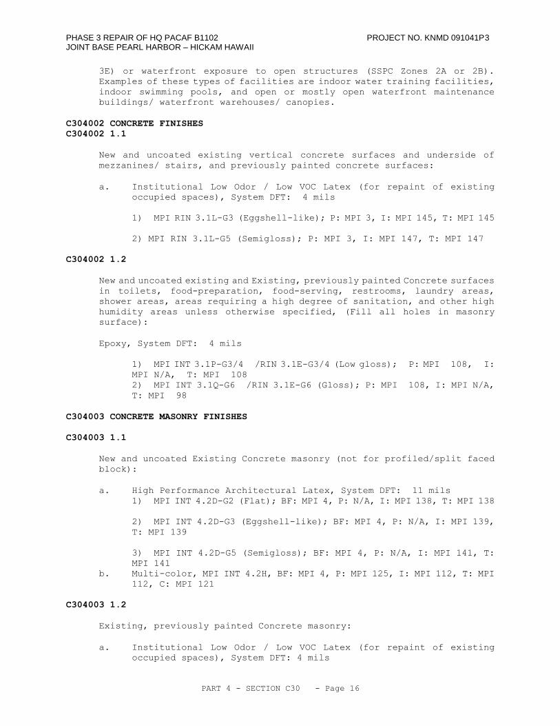
PHASE 3 REPAIR OF HQ PACAF B1102 PROJECT NO. KNMD 091041P3 JOINT BASE PEARL HARBOR – HICKAM HAWAII
PART 4 - SECTION C30 - Page 16
3E) or waterfront exposure to open structures (SSPC Zones 2A or 2B).
Examples of these types of facilities are indoor water training facilities,
indoor swimming pools, and open or mostly open waterfront maintenance
buildings/ waterfront warehouses/ canopies.
C304002 CONCRETE FINISHES
C304002 1.1
New and uncoated existing vertical concrete surfaces and underside of
mezzanines/ stairs, and previously painted concrete surfaces:
a. Institutional Low Odor / Low VOC Latex (for repaint of existing
occupied spaces), System DFT: 4 mils
1) MPI RIN 3.1L-G3 (Eggshell-like); P: MPI 3, I: MPI 145, T: MPI 145
2) MPI RIN 3.1L-G5 (Semigloss); P: MPI 3, I: MPI 147, T: MPI 147
C304002 1.2
New and uncoated existing and Existing, previously painted Concrete surfaces
in toilets, food-preparation, food-serving, restrooms, laundry areas,
shower areas, areas requiring a high degree of sanitation, and other high
humidity areas unless otherwise specified, (Fill all holes in masonry
surface):
Epoxy, System DFT: 4 mils
1) MPI INT 3.1P-G3/4 /RIN 3.1E-G3/4 (Low gloss); P: MPI 108, I:
MPI N/A, T: MPI 108
2) MPI INT 3.1Q-G6 /RIN 3.1E-G6 (Gloss); P: MPI 108, I: MPI N/A,
T: MPI 98
C304003 CONCRETE MASONRY FINISHES
C304003 1.1
New and uncoated Existing Concrete masonry (not for profiled/split faced
block):
a. High Performance Architectural Latex, System DFT: 11 mils
1) MPI INT 4.2D-G2 (Flat); BF: MPI 4, P: N/A, I: MPI 138, T: MPI 138
2) MPI INT 4.2D-G3 (Eggshell-like); BF: MPI 4, P: N/A, I: MPI 139,
T: MPI 139
3) MPI INT 4.2D-G5 (Semigloss); BF: MPI 4, P: N/A, I: MPI 141, T:
MPI 141
b. Multi-color, MPI INT 4.2H, BF: MPI 4, P: MPI 125, I: MPI 112, T: MPI
112, C: MPI 121
C304003 1.2
Existing, previously painted Concrete masonry:
a. Institutional Low Odor / Low VOC Latex (for repaint of existing
occupied spaces), System DFT: 4 mils
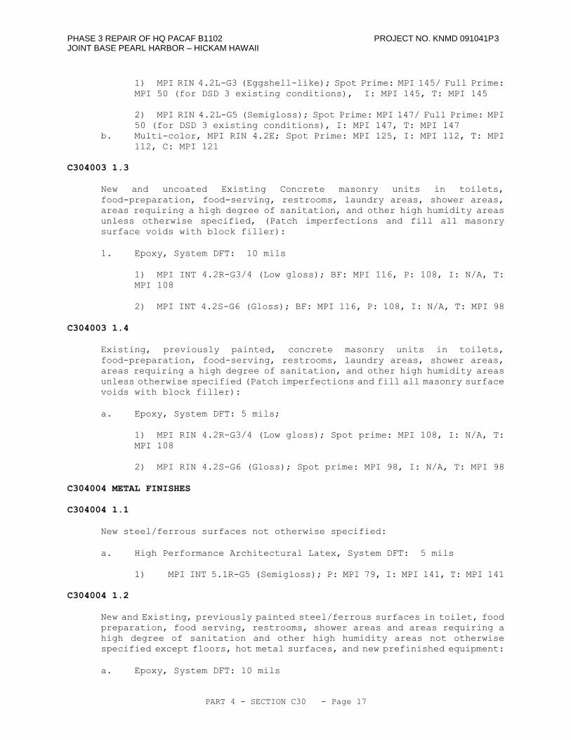
PHASE 3 REPAIR OF HQ PACAF B1102 PROJECT NO. KNMD 091041P3 JOINT BASE PEARL HARBOR – HICKAM HAWAII
PART 4 - SECTION C30 - Page 17
1) MPI RIN 4.2L-G3 (Eggshell-like); Spot Prime: MPI 145/ Full Prime:
MPI 50 (for DSD 3 existing conditions), I: MPI 145, T: MPI 145
2) MPI RIN 4.2L-G5 (Semigloss); Spot Prime: MPI 147/ Full Prime: MPI
50 (for DSD 3 existing conditions), I: MPI 147, T: MPI 147
b. Multi-color, MPI RIN 4.2E; Spot Prime: MPI 125, I: MPI 112, T: MPI
112, C: MPI 121
C304003 1.3
New and uncoated Existing Concrete masonry units in toilets,
food-preparation, food-serving, restrooms, laundry areas, shower areas,
areas requiring a high degree of sanitation, and other high humidity areas
unless otherwise specified, (Patch imperfections and fill all masonry
surface voids with block filler):
1. Epoxy, System DFT: 10 mils
1) MPI INT 4.2R-G3/4 (Low gloss); BF: MPI 116, P: 108, I: N/A, T:
MPI 108
2) MPI INT 4.2S-G6 (Gloss); BF: MPI 116, P: 108, I: N/A, T: MPI 98
C304003 1.4
Existing, previously painted, concrete masonry units in toilets,
food-preparation, food-serving, restrooms, laundry areas, shower areas,
areas requiring a high degree of sanitation, and other high humidity areas
unless otherwise specified (Patch imperfections and fill all masonry surface
voids with block filler):
a. Epoxy, System DFT: 5 mils;
1) MPI RIN 4.2R-G3/4 (Low gloss); Spot prime: MPI 108, I: N/A, T:
MPI 108
2) MPI RIN 4.2S-G6 (Gloss); Spot prime: MPI 98, I: N/A, T: MPI 98
C304004 METAL FINISHES
C304004 1.1
New steel/ferrous surfaces not otherwise specified:
a. High Performance Architectural Latex, System DFT: 5 mils
1) MPI INT 5.1R-G5 (Semigloss); P: MPI 79, I: MPI 141, T: MPI 141
C304004 1.2
New and Existing, previously painted steel/ferrous surfaces in toilet, food
preparation, food serving, restrooms, shower areas and areas requiring a
high degree of sanitation and other high humidity areas not otherwise
specified except floors, hot metal surfaces, and new prefinished equipment:
a. Epoxy, System DFT: 10 mils
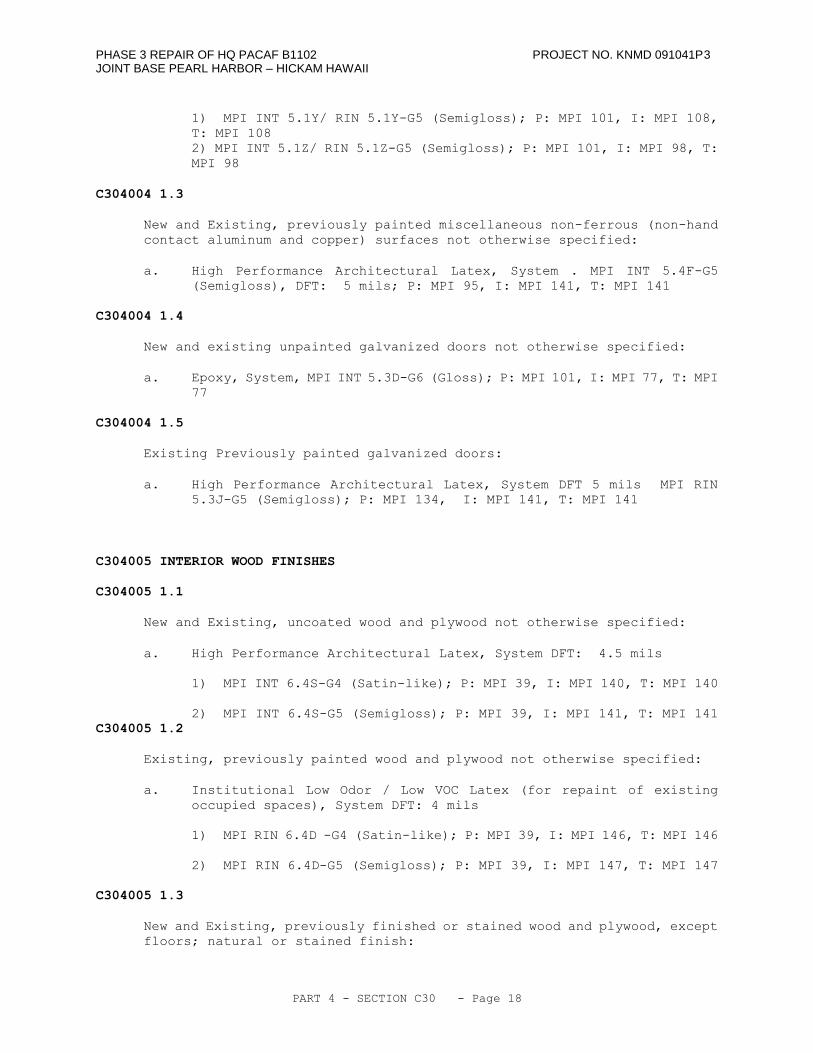
PHASE 3 REPAIR OF HQ PACAF B1102 PROJECT NO. KNMD 091041P3 JOINT BASE PEARL HARBOR – HICKAM HAWAII
PART 4 - SECTION C30 - Page 18
1) MPI INT 5.1Y/ RIN 5.1Y-G5 (Semigloss); P: MPI 101, I: MPI 108,
T: MPI 108
2) MPI INT 5.1Z/ RIN 5.1Z-G5 (Semigloss); P: MPI 101, I: MPI 98, T:
MPI 98
C304004 1.3
New and Existing, previously painted miscellaneous non-ferrous (non-hand
contact aluminum and copper) surfaces not otherwise specified:
a. High Performance Architectural Latex, System . MPI INT 5.4F-G5
(Semigloss), DFT: 5 mils; P: MPI 95, I: MPI 141, T: MPI 141
C304004 1.4
New and existing unpainted galvanized doors not otherwise specified:
a. Epoxy, System, MPI INT 5.3D-G6 (Gloss); P: MPI 101, I: MPI 77, T: MPI
77
C304004 1.5
Existing Previously painted galvanized doors:
a. High Performance Architectural Latex, System DFT 5 mils MPI RIN
5.3J-G5 (Semigloss); P: MPI 134, I: MPI 141, T: MPI 141
C304005 INTERIOR WOOD FINISHES
C304005 1.1
New and Existing, uncoated wood and plywood not otherwise specified:
a. High Performance Architectural Latex, System DFT: 4.5 mils
1) MPI INT 6.4S-G4 (Satin-like); P: MPI 39, I: MPI 140, T: MPI 140
2) MPI INT 6.4S-G5 (Semigloss); P: MPI 39, I: MPI 141, T: MPI 141
C304005 1.2
Existing, previously painted wood and plywood not otherwise specified:
a. Institutional Low Odor / Low VOC Latex (for repaint of existing
occupied spaces), System DFT: 4 mils
1) MPI RIN 6.4D -G4 (Satin-like); P: MPI 39, I: MPI 146, T: MPI 146
2) MPI RIN 6.4D-G5 (Semigloss); P: MPI 39, I: MPI 147, T: MPI 147
C304005 1.3
New and Existing, previously finished or stained wood and plywood, except
floors; natural or stained finish:
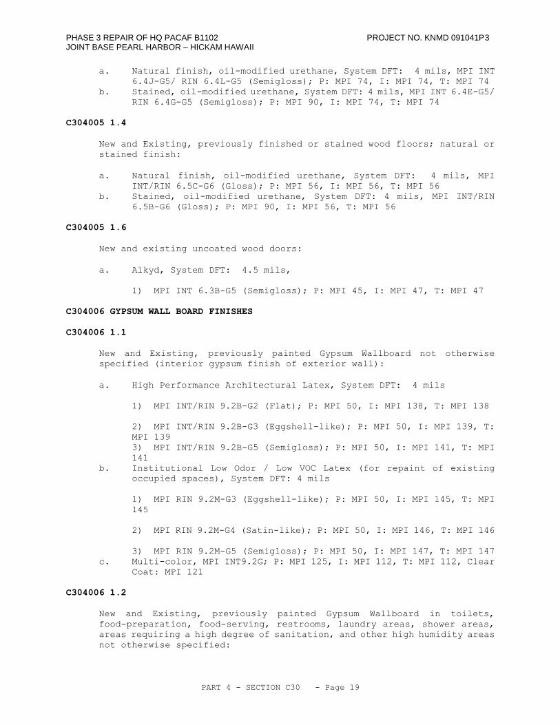
PHASE 3 REPAIR OF HQ PACAF B1102 PROJECT NO. KNMD 091041P3 JOINT BASE PEARL HARBOR – HICKAM HAWAII
PART 4 - SECTION C30 - Page 19
a. Natural finish, oil-modified urethane, System DFT: 4 mils, MPI INT
6.4J-G5/ RIN 6.4L-G5 (Semigloss); P: MPI 74, I: MPI 74, T: MPI 74
b. Stained, oil-modified urethane, System DFT: 4 mils, MPI INT 6.4E-G5/
RIN 6.4G-G5 (Semigloss); P: MPI 90, I: MPI 74, T: MPI 74
C304005 1.4
New and Existing, previously finished or stained wood floors; natural or
stained finish:
a. Natural finish, oil-modified urethane, System DFT: 4 mils, MPI
INT/RIN 6.5C-G6 (Gloss); P: MPI 56, I: MPI 56, T: MPI 56
b. Stained, oil-modified urethane, System DFT: 4 mils, MPI INT/RIN
6.5B-G6 (Gloss); P: MPI 90, I: MPI 56, T: MPI 56
C304005 1.6
New and existing uncoated wood doors:
a. Alkyd, System DFT: 4.5 mils,
1) MPI INT 6.3B-G5 (Semigloss); P: MPI 45, I: MPI 47, T: MPI 47
C304006 GYPSUM WALL BOARD FINISHES
C304006 1.1
New and Existing, previously painted Gypsum Wallboard not otherwise
specified (interior gypsum finish of exterior wall):
a. High Performance Architectural Latex, System DFT: 4 mils
1) MPI INT/RIN 9.2B-G2 (Flat); P: MPI 50, I: MPI 138, T: MPI 138
2) MPI INT/RIN 9.2B-G3 (Eggshell-like); P: MPI 50, I: MPI 139, T:
MPI 139
3) MPI INT/RIN 9.2B-G5 (Semigloss); P: MPI 50, I: MPI 141, T: MPI
141
b. Institutional Low Odor / Low VOC Latex (for repaint of existing
occupied spaces), System DFT: 4 mils
1) MPI RIN 9.2M-G3 (Eggshell-like); P: MPI 50, I: MPI 145, T: MPI
145
2) MPI RIN 9.2M-G4 (Satin-like); P: MPI 50, I: MPI 146, T: MPI 146
3) MPI RIN 9.2M-G5 (Semigloss); P: MPI 50, I: MPI 147, T: MPI 147
c. Multi-color, MPI INT9.2G; P: MPI 125, I: MPI 112, T: MPI 112, Clear
Coat: MPI 121
C304006 1.2
New and Existing, previously painted Gypsum Wallboard in toilets,
food-preparation, food-serving, restrooms, laundry areas, shower areas,
areas requiring a high degree of sanitation, and other high humidity areas
not otherwise specified:
PHASE 3 REPAIR OF HQ PACAF B1102 PROJECT NO. KNMD 091041P3 JOINT BASE PEARL HARBOR – HICKAM HAWAII
PART 4 - SECTION C30 - Page 20
a. Epoxy, Use for high humidity areas requiring easy cleaning enamel
finishes. System DFT: 4 mils,
1) MPI INT 9.2N-G3/4 / MPI RIN 9.2N-G3/4 (Low gloss) P: MPI 50, I:
MPI 108, T: MPI 108
2) MPI INT 9.2P-G6 / MPI RIN 9.2P-G6 (Gloss) P: MPI 50, I: MPI 98,
T: MPI 98
-- End of Section --
PHASE 3 REPAIR OF HQ PACAF B1102 PROJECT NO. KNMD 091041P3 JOINT BASE PEARL HARBOR – HICKAM HAWAII
PART 4 - SECTION D20 - Page 1
SECTION D20
PLUMBING
11/10
D20 GENERAL
RFP Part 3 including the Engineering System Requirements (ESR) provide project
specific requirements. The RFP Part 4 Performance Technical Sections (PTS)
provide generalized technical requirements that apply to multiple facility types
and include more requirements than are applicable to this project. Therefore RFP
Part 4 requirements that correspond and further define the RFP Part 3 requirements
are specific to this project, other RFP Part 4 requirements are not required.
D20 1.1 NARRATIVE
This section must be used in conjunction with all parts of the Design Build
(D/B) Request for Proposal (RFP) to determine the full requirements of this
solicitation.
This section includes the construction of interior plumbing systems. This
section covers installations inside the facility and out to the five foot
line. See Section G30, Site Mechanical Utilities, for continuation of
systems beyond the five foot line.
D20 1.2 PLUMBING DESIGN GUIDANCE
Provide the design and installation in accordance with the following
references. This Performance Technical Specification (PTS) adds
clarification to the fundamental requirements contained in the following
Government Standards. The general requirements of this PTS section are
located in PTS Section Z10, General Performance Technical Specification.
D20 1.2.1 Government Standards
Federal Energy Management Program (FEMP)
UNIFIED FACILITIES CRITERIA (UFC)
UFC 1-200-01
General Building Requirements(A
reference in this PTS section to UFC
1-200-01 requires compliance with the
Tri-Service Core UFCs that are listed
in UFGS Section 01 33 10.05 20, which
includes the following significant
UFC(s):UFC 3-400-10N, Mechanical
EngineeringUFC 3-420-01, Design:
Plumbing Systems)
D20 1.3 DESIGN SUBMITTALS
Design Submittals shall be in accordance with Z10, General Performance
Technical Specifications, UFGS section 01 33 10.05 20, Design Submittal
Procedures, UFC 1-300-09N, Design Proceduresand UFC 3-400-10N, Mechanical
Engineering.
D20 1.4 CONSTRUCTION SUBMITTALS
PHASE 3 REPAIR OF HQ PACAF B1102 PROJECT NO. KNMD 091041P3 JOINT BASE PEARL HARBOR – HICKAM HAWAII
PART 4 - SECTION D20 - Page 2
Submit construction submittals in accordance with PTS section Z10, General
Performance Technical Specifications. In addition to the Z10 requirements,
the Designer of Record (DOR) shall approve the following construction
submittals as a minimum:
Fixtures, equipment, and OMSI information for all equipment and fixtures.
D2010 PLUMBING FIXTURES
Plumbing fixtures shall be provided in accordance with the IBC, IPC, and as
specified.
D201001 WATER CLOSETS
D201001 1.1 FLUSH VALVE WATER CLOSETS
ASME A112.19.2, white vitreous china, siphon jet. Provide ASME A112.19.5
trim. Provide self-closing metering type flush valve, unless electronic
flush control is specified in the ESR Section D20. Electronic flush control
shall conform to UL 1951 and ASSE 1037. Flush valve shall not exceed 1.28
GPF (4.8 LPF). Handicapped fixture mounting height and appurtenances shall
be in accordance with UFAS and ADAAG.
D201001 1.2 DUAL FUNCTION FLUSH VALVE WATER CLOSETS
ASME A112.19.2, white vitreous china, siphon jet. Provide ASME A112.19.5
trim. Provide self-closing metering type dual function flush valve, unless
electronic flush control is specified in the ESR Section D20. Electronic
flush control shall conform to UL 1951 and ASSE 1037. Dual function flush
valve shall provide a flush of 0.8 to 1.1 GPF (3.0 to 4.2 LPF) or 1.28 GPF
(4.8 LPF). Maximum flush volume shall not exceed 1.28 GPF (4.8 LPF).
Handicapped fixture mounting height and appurtenances shall be in accordance
with UFAS and ADAAG.
D201001 1.3 FLUSH TANK WATER CLOSETS
ASME A112.19.2, white vitreous china, siphon jet. Provide ASME A112.19.5
trim. Water flushing volume of the water closet shall not exceed 1.28 GPF
(4.8 LPF). Handicapped fixture mounting height and appurtenances shall be
in accordance with UFAS and ADAAG.
D201001 1.4 DUAL FUNCTION FLUSH AND LOW FLOW WATER CLOSETS
ASME A112.19.2, white vitereous china, siphon jet. Provide ASME A112.19.5
trim. Dual function flush tank water closet shall provide a dual flush that
allows a flush of 0.8 to 1.1 GPF (3.0 to 1.6 LPF) or 1.28 GPF (4.8 LPF).
Maximum flush tank volume per flush shall not exceed 1.28 GPF (4.8 LPF).
Handicapped fixture mounting height and appurtenances shall be in accordance
with UFAS and ADAAG.
D201002 URINALS
D201002 1.1 FLUSH VALVE URINALS
ASME A112.19.2, white vitreous china, wall-mounted, wall outlet, siphon jet,
integral trap, extended side shields. Provide large diaphragm (not less
than 2.625 inches (66 mm) upper chamber inside diameter at the point where
PHASE 3 REPAIR OF HQ PACAF B1102 PROJECT NO. KNMD 091041P3 JOINT BASE PEARL HARBOR – HICKAM HAWAII
PART 4 - SECTION D20 - Page 3
the diaphragm is sealed between the upper and lower chambers) flush valve
of chrome plated cast brass conforming to ASTM B 584, including vacuum
breaker and angle (control-stop) valve. Maximum flush valve volume per
flush shall not exceed 0.5 gallons per flush (1.9 lpf). Provide ASME
A112.19.5 trim and ASME 112.6.1M concealed chair carriers. Provide
self-closing metering type flush valve, unless electronic flush control is
specified in the ESR Section D20. Electronic flush control shall conform
to UL 1951 and ASSE 1037.Handicapped fixture mounting height and
appurtenances shall be in accordance with UFAS and ADAAG.
D201003 LAVATORIES
D201003 1.1 COUNTERTOP LAVATORIES
Restroom lavatories shall be countertop with integral bowl and backsplash
with wall outlet. Provide ASME 112.18.1 copper alloy centerset faucets
unless self closing metering or electronic control is specified in ESR
section D20. Provide with aerator, adjustable P-traps, and perforated grid
strainers, unless pop-up drain fittings are specified in ESR section D20.
D201003 1.2 WALL-MOUNTED LAVATORIES
ASME A112.19.1, white enameled cast-iron or ASME A112.19.2 white vitreous
china with ASME A112.6.1M concealed arm carrier support, with minimum
dimensions of 20 inches wide by 18 inches (508 mm wide by 457 mm) front to
rear. Provide ASME 112.18.1 copper alloy centerset faucets unless self
closing metering or electronic control is specified in ESR section D20.
Provide with aerator, adjustable P-traps, and perforated grid strainers,
unless pop-up drain fittings are specified in ESR section D20.
D201003 1.3 HANDICAPPED LAVATORIES
Same as Paragraphs 1.1 or 1.2, except height and appurtenances shall be in
accordance with UFAS and ADAAG.
D201004 SINKS
D201004 1.1 COUNTERTOP SINKS
ASME A112.19.3 sink, 20 gage stainless steel with integral mounting rim,
minimum dimensions of 33 inches (840 mm) wide for two compartment or 21 inches
(560 mm) wide for one compartment by 21 inches (560 mm) front to rear, with
ledge back and undersides coated with sound dampening material. Provide
top-mounted ASME A112.18.1 copper alloy faucets, swing spout with aerator,
and stainless steel drain outlets with cup strainers. Provide adjustable
P-trap with drain piping to vertical vent stack. If specified in ESR section
D20, provide UL 430 waste disposer unit in right compartment.
D201004 1.2 SERVICE SINKS
ASME A112.19.1, white enameled cast-iron or ASME A112.19.2 white vitreous
china, wall mounted and floor supported by wall outlet cast-iron P-trap,
minimum dimensions of 22 inches (560 mm) wide by 18 inches (457 mm) front
to rear with 9 inch (230 mm) splashback, and stainless steel rim guard.
Provide ASME A112.18.1 copper alloy back-mounted combination faucets with
vacuum breaker and 0.75 inch (20 mm) external hose threads.
PHASE 3 REPAIR OF HQ PACAF B1102 PROJECT NO. KNMD 091041P3 JOINT BASE PEARL HARBOR – HICKAM HAWAII
PART 4 - SECTION D20 - Page 4
D201004 1.3 MOP SINKS
Pre-cast terrazzo floor-mounted mop sink, 36 inches x 36 inches x 12 inches
(914 mm x 914 mm x 305 mm) shall be made of marble chips cast in white Portland
cement to a compressive strength of not less than 3625 PSI (25 mPa) 7 days
after casting. Provide brass body drains with nickel bronze strainers cast
integral with terrazzo. Provide stainless steel rim guard for mop sink.
Provide chrome-plated exposed hot and cold water faucets ASME A112.18.1
wall-mounted copper alloy faucets swing spout with 3/4 inch (20 mm) hose
connection, vacuum breaker, and pail hook. Provide mop hanger on wall above
sink suitable for four mops.
D201006 DRINKING FOUNTAINS AND COOLERS
D201006 1.1 DRINKING FOUNTAINS
Wall mounted drinking fountain shall be constructed of white enameled cast
iron with bubbler and push button control. Handicapped fixture mounting
height and appurtenances shall be in accordance with UFAS and ADAAG.
D201006 1.2 ELECTRIC WATER COOLERS
AHRI 1010, wall-mounted, bubbler style, air-cooled condensing unit, 4.0 gph
(4.20 mL per second) minimum capacity, stainless steel splash receptor,
double wall heat exchanger, and all stainless steel cabinet. Provide ASME
A112.6.1M concealed wall hangers with thru-bolts and back plates.
Handicapped fixture mounting height and appurtenances shall be in accordance
with UFAS and ADAAG.
D201090 EMERGENCY FIXTURES
Pressure-compensated tempering valve is required for emergency fixtures, with
leaving water temperature setpoint adjustable throughout the range 60 to 95 degrees
F (15.5 and 35 degrees C) unless cold water supply meets temperature criteria.
Where indicated in ESR section D20, provide packaged, UL listed, alarm system;
including an amber strobe lamp, horn with externally adjustable loudness and horn
silencing switch, mounting hardware, and waterflow switch, assembled and prewired
for waterproof service within NEMA Type 3 or 4 enclosures or for explosion proof
service within NEMA Type 7 or 9 enclosures.
D201090 1.1 EMERGENCY SHOWER
ISEA Z358.1, wall-mounted self-cleaning, non-clogging 10 inch (250 mm)
diameter stainless steel deluge shower head with elbow, one inch (25 mm)
full-flow stay-open ball valve with pull rod and 8 inch (200 mm) diameter
ring or triangular handle, one inch (25 mm) interconnecting fittings.
D2020 DOMESTIC WATER DISTRIBUTION
D202001 PIPES & FITTINGS
D202001 1.1 COPPER
Use copper tubing and fittings for pipe sizes 4 inches (100 mm) or smaller.
Use type L tubing above ground with either solder fittings, or press-on
copper fittings. For buried piping, use type K tubing with either solder
PHASE 3 REPAIR OF HQ PACAF B1102 PROJECT NO. KNMD 091041P3 JOINT BASE PEARL HARBOR – HICKAM HAWAII
PART 4 - SECTION D20 - Page 5
fittings, or press-on copper fittings.
D202001 1.2 CHLORINATED POLYVINYL CHLORIDE (CPVC)
When specified in ESR section D20, provide CPVC pipe, fittings, and solvent
cement per ASTM D 2846/D 2846M for sizes 4 inches (100 mm) and smaller.
Provide transition union connections or threaded gate valve between metallic
piping and CPVC piping.
D202002 VALVES & HYDRANTS
D202002 1.1 VALVES
Provide valves at water supplies to fixtures and to provide ease of
maintenance as required in the IPC.
D202002 1.2 HOSE BIBBS & HYDRANTS
Use non-freeze wall hydrants where the winter design temperature is at or
below freezing. Hose bibbs are acceptable for use elsewhere.
D202002 1.2.1 Hose bibbs
Angle type, copper alloy hose bibbs with vacuum breaker.
D202002 1.2.2 Wall Hydrants
Non-freeze, ASSE 1019, cast bronze, with vacuum breaker, locking
shield and tee-handle.
D202003 DOMESTIC WATER EQUIPMENT
D202003 1.1 BACKFLOW PREVENTERS
Furnish proof that each make, model/design, and size of backflow preventer
being furnished for the project is approved by and has a current "Certificate
of Approval" from the Foundation for Cross-Connection Control and Hydraulic
Research (FCCCHR)-USC. Listing of the particular make, model/design, and
size in the current FCCCHR-USC will be acceptable as the required proof.
Provide freeze protection for aboveground exterior applications in areas
where the winter design temperature is at or below freezing.
D202003 1.2 WATER HEATERS
D202003 1.2.4 Instantaneous Water Heater (Electric)
UL 499, heater(s) shall be of the modulating, under the sink,
point-of-use type. Output temperature shall be adjustable from 40
degrees F to 160 degrees F. Heating elements shall be field
replaceable. Unit(s) shall have a 10-year warranty.
D202003 1.3 PUMPS
D202003 1.3.1 Inline Pumps
In-line circulator for service water distribution system. Factory
assembled and tested pumps constructed of materials suitable for hot
PHASE 3 REPAIR OF HQ PACAF B1102 PROJECT NO. KNMD 091041P3 JOINT BASE PEARL HARBOR – HICKAM HAWAII
PART 4 - SECTION D20 - Page 6
domestic water service.
D202003 1.3.2 Base Mounted Pumps
Potable water service, base mounted, end suction pumps with mechanical
seals and drip-proof electric motors.
D202003 1.4 DOMESTIC WATER PRESSURE BOOSTER SYSTEM
Factory assembled, tested, and certified by a single manufacturer who
assumes undivided responsibility for the system to include providing
start-up services, two days instruction and furnishing related operations
and maintenance manuals. Each building shall be provided with its own
system. Each system will consist of a minimum of two pumps mounted on a
single, welded structural steel base. Provide bladder type low-flow
accumulator storage tank, lead-lag pump alternator selector switches and
all related controls and alarms required for safe and proper system
operation. Provide variable frequency drive pump operation.
D202003 1.5 EXPANSION TANKS
Steel expansion tank with potable water rated polypropylene or butyl lined
diaphragm at water heater.
D202003 1.6 WATER METERS
AWWA C701 turbine type, with register reading in liters and U.S. gallons.
D202004 INSULATION & IDENTIFICATION
D202004 1.1 PIPING INSULATION
Mineral fiber insulation on domestic hot water supply and recirculation
piping. Insulate domestic cold water piping with cellular glass insulation
(ASTM C 552, Type II, and Type III) or polyisocyanurate insulation (ASTM
C 591, type I).
D202004 1.2 PIPING & EQUIPMENT IDENTIFICATION
In addition to the requirements in Section Z10, General Performance
Technical Specification, provide laminated plastic nameplates for valves.
Stop valves in supplies to fixtures will not require nameplates. Identify
above ground pipe with the type of service and direction of flow. Letter
size, lengths and colors shall be per ANSI A13.1.
D202005 SPECIALTIES
D202005 1.1 WASHING MACHINE CONNECTOR BOX
Recessed wall box fabricated of PVC plastic. Provide bronze dual washing
machine valve with single lever shut-off.
D202005 1.2 VALVE BOXES
For each buried valve provide cast-iron, ductile-iron box of a suitable size.
Provide cast-iron or ductile-iron cover for the box with the word "WATER"
cast on the cover.
PHASE 3 REPAIR OF HQ PACAF B1102 PROJECT NO. KNMD 091041P3 JOINT BASE PEARL HARBOR – HICKAM HAWAII
PART 4 - SECTION D20 - Page 7
D202005 1.3 WATER HAMMER ARRESTORS
PDI WH 201, water hammer arrestors in lieu of air chambers.
D202005 1.4 ICEMAKER CONNECTOR BOX
Recessed wall box fabricated of PVC plastic. Provide bronze shut-off valve.
D202090 OTHER DOMESTIC WATER SUPPLY
D202090 1.1 SUPPORTS
Provide piping supports in accordance with the IPC.
D202090 1.2 INSPECTIONS
Prior to initial operation, inspect piping system for compliance with
drawings, specifications, and manufacturer's submittals.
D202090 1.3 DISINFECTION
Upon completion of the installation, disinfect all systems per the IPC.
D202090 1.4 PLUMBING SYSTEMS TESTING
Upon completion of the installation test all systems per the IPC.
D2030 SANITARY WASTE
D203001 WASTE PIPE & FITTINGS
D203001 1.1 PIPING AND FITTINGS
Cast iron hub and spigot pipe and fittings, rubber compression gasket joints
or cast-iron hubless pipe and fittings, CISPI 301 with CISPI 310 couplings.
Where indicated in ESR Section D20, plastic PVC or ABS piping, fittings,
and solvent cement per ASTM D 2665 or ASTM D 2661 may be provided. Plastic
piping shall be equipped with approved firestopping devices as required by
code.
D203001 1.2 CLEANOUTS
Provide cleanouts as required by the IPC. Material shall be consistent with
the piping system materials.
D203002 VENT PIPE & FITTINGS
Cast-iron hubless pipe and fittings, CISPI 301 with CISPI 310 couplings. Where
indicated in ESR Section D20, plastic PVC or ABS piping, fittings, and solvent
cement per ASTM D 2665 or ASTM D 2661. PVC piping shall be equipped with approved
firestopping devices as required by code. Single drainage/vent stack systems
(such as Philadelphia system) and mechanical air admittance valves are not
acceptable.
D203003 FLOOR DRAINS
Floor drains shall be flush strainer or extended rim type as required by the IPC.
PHASE 3 REPAIR OF HQ PACAF B1102 PROJECT NO. KNMD 091041P3 JOINT BASE PEARL HARBOR – HICKAM HAWAII
PART 4 - SECTION D20 - Page 8
Provide in mechanical rooms, restrooms, fire pump room, laundry room, and plumbing
chase areas. Provide floor sinks in kitchens. Provide floor sinks where required
for interior air handling unit condensate drains.
D203004 SANITARY & VENT EQUIPMENT
D203004 1.1 PUMPS
D203004 1.1.1 Submersible Sump Pumps
Factory assembled and tested submersible type pumps for operation under
water.
D203004 1.1.2 Sewage Pumps
FS A-A-50555, single or duplex type to meet demand. Duplex types shall
be provided with automatic controls to alternate the operation from one
pump to the other.
D2040 RAIN WATER DRAINAGE
D204001 PIPE & FITTINGS
Cast iron hubless pipe and fittings, CISPI 301 with CISPI 310 couplings. Where
indicated in ESR Section D20, plastic PVC or ABS piping, fittings, and solvent
cement per ASTM D 2665 or ASTM D 2661 may be used. PVC piping shall be equipped
with approved firestopping devices as required by code. Size and install piping
in accordance with the IPC.
D204002 ROOF DRAINS
Roof drains shall conform to ASME A112.6.4, with dome and integral flange, and
shall have a device for making a watertight connection between roofing and
flashing.
D204003 RAIN WATER DRAINAGE EQUIPMENT
Where required by building design, provide expansion joint(s) of proper size to
receive the conductor pipe. The expansion joint shall consist of a heavy cast-iron
housing, brass or bronze sleeve.
D204004 INSULATION & IDENTIFICATION
Mineral fiber insulation on all drainage piping that may be subject to
condensation. Provide a vapor retarder.
D2090 OTHER PLUMBING SYSTEMS
D209001 SPECIAL PIPING SYSTEMS
D209002 ACID WASTE SYSTEMS
Acid-resistant DWV pipe, fittings, and couplings with mechanical, bell and spigot,
or fusion type joints. Material for buried piping and aboveground piping shall
be silicon-iron composition. Borosilicate glass pipe and fitting may be provided
for aboveground piping where acid composition dictates, except vent piping through
and above roofs shall be silicon-iron composition. Provide cleanouts and drains
as specified for DWV piping, except material shall be silicon-iron composition.
PHASE 3 REPAIR OF HQ PACAF B1102 PROJECT NO. KNMD 091041P3 JOINT BASE PEARL HARBOR – HICKAM HAWAII
PART 4 - SECTION D20 - Page 9
D209003 INTERCEPTORS
D209003 1.1 OIL/WATER SEPARATOR
Oil/water separator, where required, in accordance with the IPC and with
a minimum flow capacity to meet system demand.
D209003 1.2 GREASE INTERCEPTORS
Provide in accordance with the IPC and PDI G 101.
D209005 COMPRESSED AIR SYSTEM (NON-BREATHING)
D209005 1.1 AIR COMPRESSOR
Factory packaged electric motor driven, duplex air compressor including
manufacturer’s standard air filter, oil filter, and plug drain. Air
compressor, aftercooler, and receiver shall be factory packaged as a unit.
Receiver tank shall be per ASME PBVC Sec. VIII D1, labeled and rated for
125 PSI (862 kPa) gage, equipped with required valves and trimmings,
including gage and automatic drain valve and ASME BPVC pressure safety relief
valve. Air compressor and receiver shall be sized in accordance with the
Compressed Air and Gas Institute (CAGI) guidelines. Locate air compressor
away from noise sensitive areas.
D209005 1.2 REFRIGERATED AIR DRYER
Low-pressure compressed air dryer of the mechanical refrigeration type,
equipped with an automatic temperature shutdown switch to prevent freezing,
a regenerative air-to-air exchanger (as standard with the manufacturer),
and a main compressed air cooling exchanger. Refrigeration system shall
use non-CFC refrigerant and shall cool compressed air to dry the air. Dryer
operating pressure shall be not less than 125 PSI (862 kPa) gage. Dryer
size shall be based on system pressure, the entire system air flow, and
provide air with a dew point 5 degrees F (-15 degrees C) lower than the most
stringent equipment or outlet requirement. The pressure drop of the dryer
shall not exceed 2 PSI (13.8 kPa) gage.
D209005 1.3 COMPRESSED AIR PIPING SYSTEM
Piping shall conform to the requirements of ASME B31.1 for materials,
assembly, and testing. Piping shall be steel, black seamless schedule 40
carbon steel per ASTM A 53/A 53M with threaded fittings or copper tubing
per ASTM B 88, Type K or Type L, hard drawn, Class 1, with wrought copper
or bronze fittings. Provide compressed air drops in locations to facilitate
work required with quick disconnects throughout the work areas to allow
connection of such as pneumatic tools and air guns. Each air drop shall
be equipped with a filter/moisture separator, pressure gauge, air pressure
regulator, and a quick-disconnect.
-- End of Section --
PHASE 3 REPAIR OF HQ PACAF B1102 PROJECT NO. KNMD 091041P3 JOINT BASE PEARL HARBOR – HICKAM HAWAII
PART 4 - SECTION D30 - Page 1
SECTION D30
HVAC
11/10
D30 GENERAL
RFP Part 3 including the Engineering System Requirements (ESR) provide project
specific requirements. The RFP Part 4 Performance Technical Sections (PTS)
provide generalized technical requirements that apply to multiple facility types
and include more requirements than are applicable to this project. Therefore RFP
Part 4 requirements that correspond and further define the RFP Part 3 requirements
are specific to this project, other RFP Part 4 requirements are not required.
D30 1.1 NARRATIVE
This section includes the construction of interior mechanical systems. This
section covers installations inside the facility and out to the five foot
line. See Section G30, Site Civil/Mechanical Utilities, for continuation
of systems beyond the five-foot line.
D30 1.2 MECHANICAL DESIGN GUIDANCE
Provide the design and installation in accordance with the following
references. This Performance Technical Specification (PTS) adds
clarification to the fundamental requirements contained in the following
Government Standards. The general requirements of this PTS section are
located in PTS Section Z10, General Performance Technical Specification.
D30 1.2.1 Government Standards
Federal Energy Management Program (FEMP)
UNIFIED FACILITIES CRITERIA (UFC)
UFC 1-200-01
General Building Requirements(A
reference in this PTS section to UFC
1-200-01 requires compliance with the
Tri-Service Core UFCs that are listed
in UFGS Section 01 33 10.05 20, which
includes the following significant
UFC(s):UFC 3-400-10N, Mechanical
EngineeringUFC 3-420-01, Plumbing
Systems) UFC 3-440-04N
Solar Heating of Buildings and
Domestic Hot Water
UNIFIED FACILITIES GUIDE SPECIFICATIONS (UFGS)
UFGS 01 78 24.05 20
Facility Operation and Maintenance
Support Information UFGS 23 05 93
Testing, Adjusting, and Balancing for
HVAC UFGS 23 09 23.13 20
BACNET Direct Digital Control Systems
for HVAC UFGS 23 81 23.00 20
Computer Room Air Conditioning Units
PHASE 3 REPAIR OF HQ PACAF B1102 PROJECT NO. KNMD 091041P3 JOINT BASE PEARL HARBOR – HICKAM HAWAII
PART 4 - SECTION D30 - Page 2
D30 1.3 PERFORMANCE VERIFICATION AND ACCEPTANCE TESTING
a. Verification of satisfactory HVAC system performance shall be via
Performance Verification Testing, as detailed in this section.
b. The Government reserves the right to witness all Acceptance Tests and
Inspections, review data, and request other such additional
inspections and repeat tests as necessary to ensure that the system
and provided services conform to the stated requirements.
c. The Qualified Testing Organization shall provide the Acceptance Tests
and Inspections test plan and perform the acceptance tests and
inspections. Test methods, procedures, and test values shall be
performed and evaluated in accordance with appropriate standards, and
the manufacturer's recommendations. Equipment shall be placed in
service only after completion of required tests and evaluation of the
test results have been completed. Contractor shall supply to the
testing organization complete sets of shop drawings, settings of
adjustable devices, and other information necessary for an accurate
test and inspection of the system prior to the performance of any final
testing. Perform acceptance tests and inspections on Computer Room
Air Conditioning Units, Direct Digital Control System, and HVAC
Testing/Adjusting/Balancing.
D30 1.4 HVAC COMMISSIONING
Commission the HVAC systems per the Commissioning Plan as required by UFGS
Specification Section 01 45 00.05 20, Design & Construction Quality Control.
HVAC system commissioning shall coordinate with and incorporate the testing,
reporting, training & O&M documentation requirements of UFGS 23 05 93,
Testing, Adjusting, and Balancing for HVACand UFGS 23 09 23.13 20, BACnet
Direct Digital Control Systems for HVAC.
The contractor shall also measure sound within the open office space to
ensure that the system design, duct, grills, registers, and VAV terminal
units do not exceed 50 dBA.
D30 1.5 DESIGN SUBMITTALS
Design Submittals shall be in accordance with Z10, General Performance
Technical Specifications, UFGS section 01 33 10.05 20, Design Submittal
Procedures, UFC 1-300-09N, Design Procedures, and UFC 3-400-10N, Mechanical
Engineering.
In addition, UFGS sections listed below or in the body of the PTS text are
to be used by the Designer of Record (DOR) as a part of the design submittal.
If the UFGS products or systems are applicable to the project, the DOR shall
edit these referenced UFGS sections and submit them as a part of the design
submittal specification. Edit the specification sections in accordance
with the limitations stated in PTS section Z10, General Performance
Technical Specifications.
UFGS 01 78 24.05 20, Facility Operation and Maintenance Support
Information
UFGS 23 09 23.13 20, BACnet Direct Digital Control Systems for HVAC
UFGS 23 05 93, Testing, Adjusting, and Balancing for HVAC
PHASE 3 REPAIR OF HQ PACAF B1102 PROJECT NO. KNMD 091041P3 JOINT BASE PEARL HARBOR – HICKAM HAWAII
PART 4 - SECTION D30 - Page 3
UFGS 48 14 13.00 20, Solar Liquid Flat Plate Collectors
D30 1.6 CONSTRUCTION SUBMITTALS
Submit construction submittals in accordance with PTS section Z10, General
Performance Technical Specifications. In addition to the Z10 requirements,
the Designer of Record (DOR) shall approve the following construction
submittals as a minimum:
Solar hot water heating system fixtures and equipment, and OMSI
information for all equipment and fixtures.
D30 1.7 MOTORS
Single-phase fractional-horsepower alternating-current motors shall be
high efficiency types corresponding to the applications listed in NEMA MG
11. Select polyphase motors based on high efficiency characteristics
relative to the applications as listed in NEMA MG 10. Additionally, all
polyphase squirrel-cage medium induction motors with continuous ratings
shall meet or exceed energy efficient ratings per Table 12-10 of NEMA MG
1. Provide controllers for 3-phase motors rated 1 hp (0.75 kW) and above
with phase voltage monitors designed to protect motors from phase loss and
over/under-voltage. Provide means to prevent automatic restart by a time
adjustable restart relay. For packaged equipment, the manufacturer shall
provide controllers including the required monitors and timed restart.
Provide reduced voltage starters for all motors 25 hp and larger.
D3010 ENERGY SUPPLY
D301002 1.2 MATERIALS AND EQUIPMENT
D301002 1.2.1 Aboveground Within Buildings
Black steel per ASTM A 53/A 53M, Schedule 40, and associated ASME
fittings threaded ends for sizes 2 inches (50 mm) and smaller;
otherwise, plain end beveled for butt welding.
D301002 1.3 PRESSURE TESTS
Pressure test per NFPA 54 at 1.5 times maximum working pressure, but in no
case less than 50 PSI (350 kPa).
Refer to Section G30, Site Civil/Mechanical Utilities
D301004 HOT WATER SUPPLY SYSTEM (FROM CENTRAL PLANT)
Refer to Section G30, Site Civil/Mechanical Utilities
D3030 COOLING GENERATING SYSTEMS
If coatings are indicated in ESR Section D30, provide with copper tube/copper fin
construction or immersion applied, baked phenolic or other approved coating that
passes the 3000 hour salt spray resistance test using the ASTM B117 procedure.
Field applied coatings are not acceptable.
D303001 CHILLED WATER SYSTEMS
PHASE 3 REPAIR OF HQ PACAF B1102 PROJECT NO. KNMD 091041P3 JOINT BASE PEARL HARBOR – HICKAM HAWAII
PART 4 - SECTION D30 - Page 4
D303001 1.1 AIR-COOLED CHILLERS
Air-cooled chillers shall be type indicated in Project Program and meet the
requirements of AHRI 550/590. Provide control panel with the
manufacturers' standard controls and protection circuits. If DDC system
is required in project, provide a control interface for remote monitoring
of the chiller's operating parameters, functions and alarms from the DDC
control system central workstation. When using BACnet communication
protocol, use the ASHRAE 135 protocol without gateways to interface with
the BACnet DDC system in specification UFGS 23 09 13.13 20.
D303001 1.1.1 Stages
Provide continuous variable speed compressor adjustment to match
actual load, or minimum of four stages of unloading at 25% per stage
minimum for reciprocating, centrifugal, and scroll chillers.
Provide reciprocating units with hot gas bypass.
D303001 1.1.2 Pressure Control
Provide head pressure control for cold temperature operation.
Provide freeze protection for chiller and piping.
D303001 1.1.3 Coil Construction
Provide copper tube, aluminum fins for condenser coils. Provide
manufacturer's optional louvered covers or hail guards for condenser
coils to provide protection against vandalism, debris, or hail.
D303001 1.2 WATER-COOLED CHILLERS
Self-contained chiller meeting the requirements of AHRI 550/590. Provide
control panel with the manufacturers' standard controls and protection
circuits. If DDC system is required in project, provide a control interface
for remote monitoring of the chiller's operating parameters, functions and
alarms from the DDC control system central workstation. Provide automatic
capacity-reduction system for stable operation from 100 to 10 percent of
full load capacity. When using BACnet protocol, use the ASHRAE 135 protocol
without gateways to interface with the BACnet DDC system in specification
23 09 23.13 20.
D303001 1.3 COOLING TOWERS
Factory assembled, conforming to NFPA 214. Fire hazard rating for plastic
impregnated materials shall not exceed 25. Provide Cooling Technology
Institute 201 certification of tower capability and performance. Cooling
Tower performance shall meet or exceed that listed in ASHRAE 90.1.
Construct as indicated in ESR Section D30 with fill material of PVC formed
sheets. Provide stainless steel hardware. Provide vibration cutout
switch interlocked with the fan motor. Provide 2-speed or adjustable
frequency drive fan motors. Provide work platform(s) at all locations in
the tower that require periodic maintenance. For multi-cell installations,
provide isolation valves on inlets and outlets of each cell.
D303001 1.4 CLOSED CIRCUIT COOLERS
Factory assembled, conforming to NFPA 214. Fire hazard rating for plastic
PHASE 3 REPAIR OF HQ PACAF B1102 PROJECT NO. KNMD 091041P3 JOINT BASE PEARL HARBOR – HICKAM HAWAII
PART 4 - SECTION D30 - Page 5
impregnated materials shall not exceed 25. Provide Cooling Technology
Institute 201 certification of tower capability and performance. Cooler
performance shall meet or exceed that listed in ASHRAE 90.1. Provide
stainless steel hardware. Provide vibration cutout switch interlocked with
the fan motor. Provide 2-speed or adjustable frequency drive fan motors.
Meet OSHA safety requirements for stairs and handrails.
D303002 DIRECT EXPANSION SYSTEMS
If coatings are indicated in ESR Section D30, provide with copper tube/copper fin
construction or immersion applied, baked phenolic or other approved coating that
passes the 3000 hour salt spray resistance test using the ASTM B117 procedure.
Field applied coatings are not acceptable.
D303002 1.1 HEAT PUMPS
D303002 1.1.1 Air to Air
Air-cooled, split system heat pumps with ducted air distribution.
Provide units factory assembled, designed, tested, and rated in
accordance with AHRI 210/240 or AHRI 340/360. Provide manufacturer's
minimum recommended clearance around condensing units. Refrigerant
piping size shall be per the manufacturer's recommendations. Insulate
refrigerant piping suction lines and condensate drain.
D303002 1.1.2 Water Source
Factory assembled, designed, tested, and rated in accordance with
AHRI/ISO 13256-1 or AHRI/ISO 13256-2. Unit shall be AHRI/ISO 13256-1
or AHRI/ISO 13256-2 certified, or listed in the AHRI/ISO 13256-1 or
AHRI/ISO 13256-2 directory.
D303002 1.1.3 Ground-Coupled
Factory assembled, designed, tested, and rated in accordance with
AHRI/ISO 13256-1 or AHRI/ISO 13256-2. Unit shall be AHRI/ISO 13256-1
or AHRI/ISO 13256-2 certified, or listed in the AHRI/ISO 13256-1 or
AHRI/ISO 13256-2 directory. Ground-coupled heat pumps shall be
connected to the heat exchanger by a closed loop ground source vertical
well field. Design and installation of each well field shall comply
with IGSHPA and ASHRAE Standards.
D303002 1.2 CONDENSING UNITS
Air-cooled, split system air conditioner with ducted air distribution.
Provide units factory assembled, designed, tested, and rated in accordance
with AHRI 210/240 or AHRI 340/360. Provide manufacturer's minimum
recommended clearance around condensing units. Refrigerant piping size
shall be per the manufacturer's recommendations.
D303002 1.3 DX VARIABLE AIR VOLUME (VAV) UNITS
Direct expansion equipment shall be specifically designed and manufactured
for VAV applications. The same manufacturer shall provide central air
handling units, VAV boxes/zone dampers and zone controls. Airflow through
the evaporator coils shall not be modulated. Provide duct mounted zone
control damper units with integral control box, designed for use with DX
PHASE 3 REPAIR OF HQ PACAF B1102 PROJECT NO. KNMD 091041P3 JOINT BASE PEARL HARBOR – HICKAM HAWAII
PART 4 - SECTION D30 - Page 6
VAV packaged systems. Self-modulating air diffusers will not be allowed.
D303002 1.4 DUCTLESS SPLIT SYSTEM
Air-cooled, ductless split system. Provide units factory assembled,
designed, tested, and rated in accordance with ARI 210/240. Provide
manufacturer's minimum recommended clearance around heat pump or condensing
units. Refrigerant piping size shall be per the manufacturer's
recommendations. Insulate refrigerant piping suction lines and condensate
drain.
D3040 DISTRIBUTION SYSTEMS
D304001 AIR DISTRIBUTION, HEATING & COOLING
D304001 1.1 DUCTWORK
Except as specified herein, provide ductwork constructed, braced,
reinforced, installed, supported, and sealed per SMACNA standards.
D304001 1.1.1 Flexible Ducts
Use insulated flexible duct only for connections to air distribution
devices to adapt to minor offsets. Flexible duct shall be UL 181
listed and per SMACNA 1966 duct construction standards with a minimum
R value of 4. Maximum length of flexible ductwork shall be 6 feet
(2 meters).
D304001 1.1.2 Flexible Connections
Provide flexible connectors between fans and ducts.
D304001 1.1.3 Volume Dampers
Provide manual volume dampers in each branch take-off from the main
duct to control air quantity except for primary supply ductwork on
VAV systems. Dampers shall conform to SMACNA 1966 duct construction
standards and shall be seal class "A" construction.
D304001 1.1.4 Fire Dampers
Fire dampers shall be rated per UL 555. Fire dampers shall be dynamic
type rated for closure against a moving airstream. Provide fire
dampers that do not intrude into the air stream when in the open
position.
D304001 1.1.5 Smoke Dampers
Smoke dampers shall be rated per UL 555S.
D304001 1.1.6 Sound Attenuators
Fabricated attenuators that will reduce the rated sound pressure level
of the fan down to at least 65 decibels in the 250 Hz (third octave
band) center frequency by using a reference sound source calibrated
in decibels of sound power at 10 to 12 watts. Maximum permissible
pressure drop shall not exceed 0.63 inch of water (157 Pa).
PHASE 3 REPAIR OF HQ PACAF B1102 PROJECT NO. KNMD 091041P3 JOINT BASE PEARL HARBOR – HICKAM HAWAII
PART 4 - SECTION D30 - Page 7
Sound attenuation and masking shall be used to ensure duct
penetrations meet the STC requirements of the wall they are installed.
D304001 1.2 LOUVERS & HOODS
D304001 1.2.1 Louvers
Louvers shall bear AMCA ratings seal for air performance and water
penetration in accordance with AMCA 500L and AMCA 511. Louvers shall
be constructed of anodized aluminum alloy or stainless steel.
Provide birdscreens.
D304001 1.2.2 Hoods
Hoods shall be constructed of anodized aluminum alloy or stainless
steel. Provide with birdscreens.
D304001 1.3 GRILLES, REGISTERS, & DIFFUSERS
Factory-finished grilles, registers, and diffusers. Exterior and exposed
edges shall be rolled, or otherwise stiffened and rounded.
D304001 1.4 INSULATION
Provide external thermal insulation for all ductwork. Insulate ductwork
in concealed spaces with blanket flexible mineral fiber. Insulate ductwork
in Mechanical Rooms and exposed locations with rigid mineral fiber
insulation.
Provide insulation with factory applied all-purpose jacket with integral
vapor retarder. In exposed locations, provide a jacket with white surface
suitable for painting. Flame spread/smoke developed rating for all
insulation shall not exceed 25/50. Minimum insulation thickness shall be
the minimum thickness required by ASHRAE 90.1. Insulate the backs of all
supply air diffusers with blanket flexible mineral fiber insulation.
D304001 1.5 VAV BOXES
Pressure-independent type variable air volume units rated per AHRI 880.
Boxes shall not be allowed to fully shut-off. Provide each box with a heating
coil unless not required by space reheat or heating. Provide electronic
controls.
D304001 1.6 VARIABLE AIR VOLUME VAV FAN-POWERED UNITS
Pressure-independent, fan powered, VAV units rated per AHRI 880 and UL
listed. Provide each box with a heating coil. Provide electronic controls
with speed controller, discharge volume control damper(s), and
return/recirculation air frame and filter. If discharge dampers are not
provided with the unit, coordinate installation with the sheet metal
contractor. Insulate in accordance with ASHRAE 90.1.
D304005 GLYCOL DISTRIBUTION SYSTEMS
Provide as specified for Chilled Water Distribution Systems see D304006.
D304006 CHILLED / CONDENSER WATER DISTRIBUTION SYSTEMS
PHASE 3 REPAIR OF HQ PACAF B1102 PROJECT NO. KNMD 091041P3 JOINT BASE PEARL HARBOR – HICKAM HAWAII
PART 4 - SECTION D30 - Page 8
D304006 1.1 ABOVEGROUND CHILLED AND CONDENSER WATER PIPING
Aboveground chilled water piping shall be electric resistance welded or
seamless Schedule 40 black steel pipe conforming to ASTM A 53/A 53M. Piping
4 inch (100 mm) and smaller may be ASTM B 88 Type K or L copper.
D304006 1.2 STEEL PIPE FITTINGS
For piping 2 inch (50 mm) and smaller, provide ASME B16.3 malleable iron
screwed fittings or ASME B16.11 socket welding (Class 3000) or threaded type
(Class 2000). Provide ASME B16.9 butt-welding fittings or ASME B16.5
flanged type for piping 2-1/2 inch (63 mm) and larger.
D304006 1.3 COPPER FITTINGS
ASME B16.18 cast bronze solder joint type or ASME B16.22 wrought copper
solder joint type.
D304006 1.4 ISOLATION VALVES
Provide isolation valves on supply and return lines at take-offs for service
to each building(s). Valves shall be located in valve boxes.
D304006 1.5 INSULATION
Insulate chilled water pumps and accessories for the temperature and service
in rigid block, semi-rigid board, or flexible unicellular insulation to fit
as closely as possible to equipment. Insulate above ground chilled water
piping with cellular glass insulation (ASTM C 552, Type II, and Type III)
or polyisocyanurate insulation (ASTM C 591, type I). Flexible unicellular
insulation may be used on small piping runouts. Insulate condenser water
piping with mineral fiber insulation. Provide all-purpose jacket with
vapor retarder. Provide aluminum metal wrap over insulation for all
exterior piping.
D304006 1.6 VALVES
Provide shut off valves, appropriately sized relief valves, and
appropriately sized balancing valves as necessary to balance water flows,
protect components and isolate equipment for service and repairs.
D304006 1.7 TEST PORTS
Provide test ports in piping at inlet and outlet of all major system
components including chillers, pumps, and other equipment as required.
D304007 EXHAUST SYSTEMS
D304007 1.1 FANS
Fans shall be AMCA 210 certified, with AMCA seal. Fan bearings shall have
a minimum average life of 200,000 hours at design operating conditions.
Provide bird screens for outdoor inlets and outlets. Provide direct-drive
type fans with means for verifying operation via the building DDC system
or with speed controllers
PHASE 3 REPAIR OF HQ PACAF B1102 PROJECT NO. KNMD 091041P3 JOINT BASE PEARL HARBOR – HICKAM HAWAII
PART 4 - SECTION D30 - Page 9
D304007 1.2 IN-LINE FANS
UL-Listed centrifugal fans.
D304007 1.3 WALL FANS
Propeller fans with fan guards. Provide centrifugal fans with backdraft
dampers and wall bracket.
D304007 1.4 ROOFTOP FANS
UL-Listed centrifugal fans with roof curb.
D304007 1.5 UTILITY SETS
AMCA 210 with AMCA seal.
D304007 1.6 BATHROOM FANS
UL 507 and UL-listed, Home Ventilating Institute (HVI) certified and with
AMCA seal for ceiling installation.
D304007 1.7 RANGE HOODS
UL 507 and UL-listed, with AMCA seal, range hood with light over stove.
Minimum fan capacity shall be 160 cfm with maximum sound level of 5.6 sones.
D304008 AIR HANDLING UNITS
AMCA 210 certified fans with AMCA seal. Fan bearings shall have a minimum average
life of 200,000 hours at design operating conditions. Provide bird screens for
outdoor inlets and outlets.
D304008 1.1 CENTRAL STATION AIR HANDLERS
Modular construction, double wall air handling units with minimum of 1 inch
(25 mm) casing insulation. Provide AHRI 430 certified fans and AHRI
certified coils. Provide stainless steel, positive draining condensate
drain pan. For 100% outside air units provide capability for cooling,
heating, dehumidification and reheat.
D304008 1.1.1 Ultraviolet Disinfection System
For central station air handling units provide an ultra violet c-band
(UVC) disinfection system for mold, bacteria and odor control in each
air handler that has a chilled water or DX cooling coil.
Irradiation-emitters and fixtures are to be installed in sufficient
quantity and in such an arrangement so as to provide an equal distribution
of UVC energy on the coil and in the drain pan. To maintain energy
efficiency, the UVC energy produced shall be of the lowest possible
reflected and shadowed losses. Energy Efficiency - Power supplies shall
be of the high efficiency electronic type and matched to the emitter.
Intensity - The minimal UVC energy striking the leading edge (if installed
upstream) or trailing edge (if installed downstream) of all the coil fins
shall not be less than 820 µW/cm2 at the closest point and through
placement, not less than 60% of that value at the farthest point. Equal
amounts are to strike the drain pan, either directly or indirectly through
PHASE 3 REPAIR OF HQ PACAF B1102 PROJECT NO. KNMD 091041P3 JOINT BASE PEARL HARBOR – HICKAM HAWAII
PART 4 - SECTION D30 - Page 10
reflection. The foregoing sets the placement and minimum quantity of
fixtures to be installed. Installation - emitters and fixtures shall
be installed at right angles to the conforming lines of the coil fins,
such that through incident angle reflection, UVC energy bathes all
surfaces of the coil and drain pan as well as all of the available line
of sight airstream. One complete set of spare bulbs will be supplied.
D304090 OTHER DISTRIBUTION SYSTEMS
D304090 1.1 PUMPS
Centrifugal circulating pumps with motor, motor starter, and motor enclosure
conforming to the appropriate NEMA standards. Provide suction diffusers
on base-mounted pumps. Insulate pumps used for hot service and chilled
water service.
D304090 1.1.1 In-Line Pumps
Pumps constructed of manufacturer's standard materials suitable for
chilled, condenser, and hot water heating systems.
D304090 1.1.2 Base Mounted Pumps
Single stage end suction pumps suitable for chilled, condenser, and
hot water heating systems.
D304090 1.2 VARIABLE FREQUENCY DRIVES (VFD)
Factory-assembled variable frequency drive control systems for variable
speed control. All air handling unit and pump VFD's shall be from the same
manufacturer. Each VFD shall include motor starter, motor disconnects and
controls as required for a complete system. Units shall be UL-listed and
comply with the National Electric Code.
Provide the following accessories:
Disconnect switch
Control circuit transformer, with primary and secondary fuses
Manual bypass
System hand-off-auto switch with provisions for remote start/stop of the
system.
System initialized light
Run light
Failure alarm
LCD digital display with numeric keypad
Provide a control interface for remote monitoring of VFD functions and
alarms from the DDC control system computer.
D304090 1.3 CHILLED WATER AND HOT WATER AIR SEPARATORS
ASME rated air separators with tangential inlet and outlet connections and
automatic air vent.
D304090 1.4 SOLIDS SEPARATORS
Provide centrifugal solids separator with automatic drain in open systems.
PHASE 3 REPAIR OF HQ PACAF B1102 PROJECT NO. KNMD 091041P3 JOINT BASE PEARL HARBOR – HICKAM HAWAII
PART 4 - SECTION D30 - Page 11
D304090 1.5 EXPANSION TANKS
ASME rated expansion tanks with polypropylene or butyl diaphragm or
compression tanks as indicated in UFC 3-400-10N.
D304090 1.6 MAKE-UP WATER STATION
Station shall consist of a water pressure-reducing valve, filter and relief
valve in the make-up water line to the chilled and hot water systems to
maintain the operating pressure. Provide a 3/4 inch (20 mm) globe valve
by-pass around this pressure reducing station. Provide reduced pressure
backflow preventer upstream of the by-pass.
D304090 1.7 GLYCOL MAKE-UP STATION
If required, provide a glycol makeup system to maintain system proper
operating mixture.
D304090 1.8 CONDENSATE DRAIN PIPING
ASTM B 88, Type M or L, hard drawn copper.
D304090 1.9 CONDENSATE DRAIN INSULATION
Insulate condensate drain piping with flexible cellular insulation.
D304090 1.10 CHEMICAL TREATMENT
If required, Provide chilled and hot water systems with automatic chemical
treatment system for the control of pH, scale formation, and corrosion
inhibition. Provide shot-type feeders for manual chemical feed. Feeders
shall be rated for use with pressures up to 130 PSI (900 kPa) (gage). Provide
condenser water systems with automatic chemical treatment systems that
monitor conductivity, and pH, and provide for water metering and bleed-off.
Provide chemicals in accordance with EPA and equipment manufacturer’s
recommendations.
D304090 1.11 PIPING IDENTIFICATION
Provide piping identification labels or Stencil names or code letters for
piping systems in clearly visible letters and symbols. Provide
arrow-shaped markings to indicate direction of flow.
D304090 1.12 PIPE SLEEVES
Provide pipe sleeves at each wall and floor penetration. The sleeve shall
be of a material suitable to protect the carrier pipe (two pipe sizes larger)
and sealed with an appropriate flexible material. Provide fire stopping
in fire rated walls in accordance with IBC.
D304090 1.13 SYSTEM FLUSHING
Thoroughly flush hydronic systems prior to system startup. Isolate coils
during initial flushing until water is clear.
D304090 1.14 HEAT TAPE
PHASE 3 REPAIR OF HQ PACAF B1102 PROJECT NO. KNMD 091041P3 JOINT BASE PEARL HARBOR – HICKAM HAWAII
PART 4 - SECTION D30 - Page 12
UL-Listed, self-regulating, heat tape on piping subject to freezing.
D3050 TERMINAL & PACKAGE UNITS
D305002 1.2 HOT WATER
UL-Listed, factory assembled, unit heaters.
D305003 FAN COIL UNITS
UL-Listed, factory assembled and tested fan coils, AHRI 440 and AHRI certified.
D305006 PACKAGE UNITS
D305006 1.1 ROOFTOP AIR HANDLERS
Factory packaged units in accordance with AHRI 430 and suitable for outdoor
installation. Provide with manufacturer's roof curb.
D3060 CONTROLS AND INSTRUMENTATION
D306001 HVAC CONTROLS
D306001 1.1 DIRECT DIGITAL CONTROLS
Provide one of the following as directed in ESR Section D30.
a. Provide Direct Digital Controls (DDC) to comply with the requirements
specified in UFGS Section 23 09 23.13 20, BACNET Direct Digital Control
Systems for HVAC.
b. Provide a partial direct digital control (DDC) system to that will
communicate with the existing DDC system. If using BACnet protocol,
comply with the requirements specified in UFGS Section 23 09 23.13
20, BACnet Direct Digital Control Systems for HVAC. Notwithstanding
any other provisions of this contract, no other product will be
acceptable other than that indicated in ESR Section D30. Provide a
distributed control system. Integrate all new DDC points on the
existing server providing a seamless logical flow from the existing
facilities to the new integrated facility.
The Designer of Record shall use UFGS Section 23 09 23.13 20 if using BACnet
protocol, and submit the edited specification section as a part of the
project design submittal.
Design requirements shall be in accordance with all specification notes and
the BAS Owner shall be identified and designated early in the design
documentation.
The system shall have stand alone digital controllers, a communication
network, and a workstation computer with control software. Provide
stand-alone control routines that operate without connection to the network
during a loss of communication. Provide trending, scheduling and alarm
tables (may be included with the sequence of operation). Provide reset
routines (based on outdoor air temperature or zone demand) for hot water
loop temperature setpoints and supply air static pressure control. Use
alarming and trending services during performance testing or commissioning.
Alarm every sequence routine when out-of-limits or control/response failure
PHASE 3 REPAIR OF HQ PACAF B1102 PROJECT NO. KNMD 091041P3 JOINT BASE PEARL HARBOR – HICKAM HAWAII
PART 4 - SECTION D30 - Page 13
occurs. Display all graphic floor plans, equipment graphics, DDC ladder
diagrams, and sequence of operations graphic pages.
All 120-volt wiring shall comply with NFPA 70. All 24-volt wiring shall
comply with the IMC and terminal device manufacturer’s recommendations.
Provide training on the installed system according to the maximum training
days in UFGS 23 09 23.13 20. All operator workstation functions requiring
BACnet services, i.e., navigating through the graphic displays, trending,
alarming and monitoring of the new controls system must be demonstrated from
the existing operator workstation using only the existing application
software and without the need to launch other applications or logon to other
vendor applications.
D306001 1.2 ELECTRONIC CONTROLS
If required, provide programmable thermostats with built in keypads for
scheduling of day and night temperatures with two setback periods per day.
Provide independent summer and winter programs. Thermostats shall have
temporary and manual override of schedule and battery backup.
D3070 SYSTEMS TESTING AND BALANCING
D3070 1.1 HVAC SYSTEM
Provide HVAC systems testing and balancing that complies with the
requirements specified in UFGS Specification Section 23 05 93, Testing,
Adjusting, and Balancing for HVAC. The Designer of Record shall prepare
UFGS Specification Section 23 05 93, as a part of the project specification
and shall include the prepared specification section in the design submittal
for the project.
D3090 OTHER HVAC SYSTEMS AND EQUIPMENT
D309001 GENERAL CONSTRUCTION ITEMS
D309001 1.1 SEISMIC DESIGN
Provide in accordance with UFC 3-400-10N, Mechanical Engineering.
D309002 REFRIGERATION SYSTEMS
D309090 OTHER SPECIAL MECHANICAL SYSTEMS
D309090 1.1 ENERGY RECOVERY WHEELS
Total energy (enthalpy) type energy recovery wheels (heat wheels). Media
shall be aluminum or a lightweight polymer coated with a corrosion-resistant
finish. Etched or oxidized surfaces are not acceptable. Heat transfer
surfaces shall be coated with a non-migrating (permanently bonded) absorbent
specifically developed for the selective transfer of water vapor. Equal
sensible and latent recovery efficiencies shall be documented through a
certification program conducted per ASHRAE 84 and AHRI 1060. The energy
recovery wheel shall have an insulated housing of double wall construction,
rotor seals that are specifically designed to limit cross-contamination,
and a rotation detector. Should rotation stop, the rotation detector shall
alarm the HVAC control system. Filter sections shall be readily accessible

PHASE 3 REPAIR OF HQ PACAF B1102 PROJECT NO. KNMD 091041P3 JOINT BASE PEARL HARBOR – HICKAM HAWAII
PART 4 - SECTION D30 - Page 14
for maintenance.
-- End of Section --
PHASE 3 REPAIR OF HQ PACAF B1102 PROJECT NO. KNMD 091041P3 JOINT BASE PEARL HARBOR – HICKAM HAWAII
PART 4 - SECTION D40 - Page 1
SECTION D40
11/10
D40 GENERAL
RFP Part 3 including the Engineering System Requirements (ESR) provide project
specific requirements. The RFP Part 4 Performance Technical Sections (PTS)
provide generalized technical requirements that apply to multiple facility types
and include more requirements than are applicable to this project. Therefore RFP
Part 4 requirements that correspond and further define the RFP Part 3 requirements
are specific to this project, other RFP Part 4 requirements are not required.
D40 1.1 DESIGN GUIDANCE
Provide the design and installation of fire protection systems in accordance
with the following references. This Performance Technical Specification
(PTS) adds clarification to the fundamental requirements contained in the
following Government Standards. The general requirements of this PTS
section are located in PTS Section Z10, General Performance Technical
Specification.
D40 1.1.1 Government Standards
UNIFIED FACILITIES CRITERIA (UFC)
UFC 1-200-01
General Building Requirements(A
reference in this PTS section to UFC
1-200-01 requires compliance with the
Tri-Service Core UFCs that are listed
in UFGS Section 01 33 10.05 20, which
includes the following significant
UFC(s):UFC 3-600-01, Fire Protection
Engineering for Facilities)
UFC 3-600-10N
Fire Protection Engineering
D40 1.2 QUALITY ASSURANCE
Materials and assemblies installed in the work shall be inspected and found
to be in compliance with industry standards and these specifications prior
to acceptance of the work. Items found not to be in compliance shall be
removed, or corrective measures taken, to assure compliance with the
referenced standard.
Qualifications, Training Plans, and Test Plans and Procedures indicated
herein, shall be submitted 45 calendar days prior to the expected date of
execution. Notify the Contracting Officer 14 calendar days prior to all
testing. Submit test results within 7 calendar days of completion of testing.
D40 1.2.1 Qualified Workers
D40 1.2.1.1 Fire Protection Designer of Record
Services and qualifications of the FPDOR shall be as specified in UFC
3-600-01 and UFC 3-600-10N. The FPDOR shall review and approve all
fire protection engineering submittals.
PHASE 3 REPAIR OF HQ PACAF B1102 PROJECT NO. KNMD 091041P3 JOINT BASE PEARL HARBOR – HICKAM HAWAII
PART 4 - SECTION D40 - Page 2
D40 1.2.1.2 Fire Protection Engineering Technicians
Workers required herein to be certified by the National Institute for
Certification in Engineering Technologies (NICET) as an engineering
technician in the Fire Protection Engineering Technology program
shall be thoroughly trained and experienced, and completely familiar
with the specified requirements and the methods needed for proper
performance of the work in this section. All documentation required
to be submitted for record and/or approval shall include the NICET
engineering technician's signature, along with the technician's
current NICET certification number, certification subfield, and
level.
Installation drawings, shop drawings or working plans, calculations,
other required pre-construction documentation and as-built drawings
shall be prepared by, or under the direct supervision of a NICET
engineering technician as specified in Section 6 D40 of Part 3.
D40 1.2.1.3 Qualified System Installers
Fire Suppression System and Fire Alarm System installers shall be
regularly engaged in the installation of the type and complexity of
system specified in the Contract documents, and shall have served in
a similar capacity for at least three systems that have performed in
the manner intended for a period of not less than 6 months.
Installers of Chlorinated Poly Vinyl Chloride (CPVC) sprinkler
systems shall be certified by the manufacturer and maintain a copy
of their certification on hand at all times.
D40 1.2.1.4 Fire Protection QC Specialist
The Fire Protection (FP) QC Specialist shall be a U.S. Registered Fire
Protection Engineer (FPE) and shall be an integral part of the Prime
Contractor's Quality Control Organization. This FPE shall have no
business relationships (owner, partner, operating officer,
distributor, salesman, or technical representative) with any fire
protection equipment device manufacturers, suppliers or installers
for any such equipment provided as part of this project. The Fire
Protection Designer of Record (FPDOR) may serve as the FPQC Specialist
provided the following qualifications are met.
a. Qualifications/Experience: The FPQC Specialist shall have
obtained their professional registration by successfully
completing the Fire Protection Engineering discipline
examination. This FPE shall have a minimum of 5 years full time
and exclusive experience in every aspect of facility design and
construction as it relates to fire protection, which includes, but
is not limited to, building code analysis, life safety code
analysis, design of automatic detection and suppression systems,
passive fire protection design, water supply analysis, and a
multi-discipline coordination reviews, and construction
surveillance.
b. Area of Responsibility: The FPQC Specialist is responsible for
assuring the proper construction and installation of life safety
and fire protection features across all disciplines and trades.
The FPQC Specialist shall be responsible for assuring that life
PHASE 3 REPAIR OF HQ PACAF B1102 PROJECT NO. KNMD 091041P3 JOINT BASE PEARL HARBOR – HICKAM HAWAII
PART 4 - SECTION D40 - Page 3
safety and fire protection features are provided in accordance with
the design documents, approved construction submittals, and
manufacturer's requirements. Examples include, but are not
limited to, water distribution systems including fire pumps and
fire hydrants, fire resistive assemblies such as spray-applied
fire proofing of structural components and fire rated
walls/partitions, fire alarm and detection systems, fire
suppression and standpipe systems, and emergency and exit lighting
fixtures.
c. Construction Surveillance: The FPQC Specialist shall visit the
construction site as necessary to ensure life safety and fire
protection systems are being constructed, applied, and installed
in accordance with the approved design documents, approved
construction submittals, and manufacturer's requirements.
Frequency and duration of the field visits are dependent upon
particular system components, system complexity, and phase of
construction. At a minimum, field visits shall occur just prior
to installation of suspended ceiling system to inspect the
integrity of passive fire protection features and fire suppression
system piping, preliminary inspections of fire alarm/detection and
suppression systems, and final acceptance testing of fire
alarm/detection and suppression systems. The FPQC Specialist
shall prepare a written report detailing compliance of any
outstanding submittal review comments, summarizing the results of
all tests, detailing all discrepancies discovered, corrective
action taken, all forms as required by the respective NFPA codes,
and recommendations/certifications for acceptance. Forward one
copy of the report with attachments to the Naval Facilities
Engineering Command Fire Protection Engineer.
D40 1.2.2 Performance Verification Testing
All systems shall have operational tests to demonstrate compliance with
contract requirements and respective NFPA codes, International Building
Code and as noted below. Test procedures shall be in full compliance with
the respective NFPA codes, the equipment manufacturer recommendations, and
UFC 3-600-10N. Provide all personnel, equipment, and materials for tests.
Return trips to witness repeat acceptance tests due to failure of previous
tests will be at the Contractor’s expense.
D40 1.2.2.1 Preliminary Inspections and Final Acceptance Testing
The FPQC Specialist shall personally witness all preliminary
inspections of fire alarm/detection and suppression systems. Once
preliminary inspections have been successfully completed, the FPQC
Specialist shall submit a signed certificate to the QC Manager that
systems are ready for final inspection and testing. The Naval
Facilities Engineering Command Fire Protection Engineer will witness
formal tests and approve all systems before they are accepted. The
QC Manager shall submit the request for formal inspection at least
15 days prior to the date the inspection is to take place. The QC
manager shall provide 10 days advance notice to the Contracting
Officer and the activity Fire Inspection Office of scheduled final
inspections.
D40 1.2.2.2 Final Life Safety/Fire Protection Certification
PHASE 3 REPAIR OF HQ PACAF B1102 PROJECT NO. KNMD 091041P3 JOINT BASE PEARL HARBOR – HICKAM HAWAII
PART 4 - SECTION D40 - Page 4
The FPQC Specialist shall provide certification that all life safety
and fire protection systems have been installed in accordance with
the contract documents, approved submittals, and manufacturer's
requirements. This certification shall summarize all life safety and
fire protection features, and shall bear the professional seal of the
FPQC Specialist.
D40 1.2.2.3 System Manufacturers Representatives
The systems manufacturer technical representative shall be present
for the final inspection and test for the following systems: fire
alarm and detection, fire pump, carbon dioxide, foam generating and
clean agent extinguishing.
D40 1.2.2.4 Fire Suppression Water Supply and Equipment
The fire hydrants shall be inspected prior to backfilling the trench
surrounding the fire hydrants. A report, including pictures, shall
be provided to the Contracting Officer.
Fire pump tests shall be conducted in the presence of the pump,
controller, and engine manufacturer technical representatives. The
fire pump manufacturer shall also be present for the preliminary test
of the fire pump system.
D40 1.2.2.6 Spray-Applied Fire Proofing and Fire Stopping
See Section C1030 for requirements.
D40 1.2.3 Training
The contractor shall provide training for the active systems within 6 weeks
of final acceptance of the systems. The training shall be scheduled at least
2 weeks in advance.
D40 1.3 DESIGN SUBMITTALS
Design Submittals shall be in accordance with Z10, General Performance
Technical Specifications, UFGS section 01 33 10.05 20, Design Submittal
Procedures, UFC 1-300-09N, Design Procedures and UFC 3-600-10N, Fire
Protection Engineering.
D40 1.4 CONSTRUCTION SUBMITTALS
Submit construction submittals in accordance with PTS Section Z10, General
Performance Technical Specifications. In addition to the Z10 requirements,
the Designer of Record (DOR) shall approve the following construction
submittals as a minimum:
All fire protection engineering submittals including:
a. Shop Drawings. Provide shop drawings for all systems.
b. Product Data. Provide product data for all equipment.
c. Design Data. Provide design data for all system calculations.
d. Test Reports
e. Certificates
D4010 FIRE ALARM AND DETECTION SYSTEMS
PHASE 3 REPAIR OF HQ PACAF B1102 PROJECT NO. KNMD 091041P3 JOINT BASE PEARL HARBOR – HICKAM HAWAII
PART 4 - SECTION D40 - Page 5
D401001 FIRE ALARM DISTRIBUTION
D401001 1.1 REMOTE ANNUNCIATORS
Remote annunciators shall have a minimum 80 character alphanumeric display
with alarm acknowledge, alarm silence, and reset functions.
D401001 1.2 TRANSMITTED SIGNALS
Provide the following signals to be sent to the fire alarm receiving station:
a. Sprinkler Water Flow
b. Smoke Detector
c. Manual Pull Station
d. Supervisory (i.e., valve tamper switch, fire pump loss of power, fire
pump phase reversal)
e. Duct Smoke Detector
f. Fire Pump Running
g. Sleeping Room Smoke Detector
D4020 FIRE SUPPRESSION WATER SUPPLY AND EQUIPMENT
D402001 FIRE PROTECTION WATER PIPING AND EQUIPMENT
The design point of connection to the existing water supply shall require the
approval of the Contracting Officer. The FP DOR shall conduct additional flow
tests after contract award prior to any design submissions. Tests shall be
conducted under the supervision of the Contracting Officer.
D4040 SPRINKLERS
D404001 SPRINKLERS & RELEASING DEVICES
D404001 1.1 DESCRIPTION
Areas subject to freezing shall be provided with a dry pipe system. Loading docks
may be protected with dry-type sidewall sprinklers supplied by the wet-pipe system.
D404001 1.2 REQUIREMENTS
Utilize upright sprinklers with ordinary temperature rating and color to match
finish in normally occupied rooms without a finished ceiling (i.e., laboratories,
and other spaces with exposed ceilings).
D4090 OTHER FIRE PROTECTION SYSTEMS
D409001 CARBON DIOXIDE SYSTEMS
Supply shall include storage cylinders, racks, manifolds, beam scales, and
associated equipment. Arrange the primary cylinders for automatic discharge upon
activation of the main control, and the secondary cylinders for discharge both
manually and upon no discharge from the primary cylinders.
D409002 FOAM GENERATING EQUIPMENT
D409002 1.1 SYSTEM CRITERIA
Foam fire protection systems shall incorporate the necessary elements for
PHASE 3 REPAIR OF HQ PACAF B1102 PROJECT NO. KNMD 091041P3 JOINT BASE PEARL HARBOR – HICKAM HAWAII
PART 4 - SECTION D40 - Page 6
foam storage, pumping, piping, proportioning, delivery, and detection,
activation and alarm systems.
D409002 1.2 SYSTEM OPERATION
Once activated, foam system(s) shall operate until shut down manually.
Provide separate circuits from the releasing control panel to each zone of
initiating devices. Transmission of signals from more than one zone over
a common circuit is prohibited.
D409002 1.3 AFFF CONCENTRATE PUMPS
The foam concentrate pump shall be positive displacement, electric motor
driven, drip proof, 240/480 volts, 60 Hz AC. System operation shall be fully
automatic, with manual over-ride and manual shutdown.
D409002 1.4 FOAM CONCENTRATE STORAGE TANK
A gage or unbreakable sight glass shall permit visual determination of level
of tank contents, unless liquid level is clearly visible through shell of
tank.
D409002 1.5 LOW-LEVEL LOW-EXPANSION FOAM SYSTEM
D409002 1.5.1 Discharge Devices
Where used the low-level AFFF nozzle system shall utilize the Viking Grate
Nozzle TM, Model GN 200 (or equivalent that is acceptable to the NAVFAC Chief
Fire Protection Engineer for this use).
D409002 1.5.2 Test Header
Where used a foam system test header connection with integral gate valves
shall be located at each foam system riser. Sufficient 2-1/2 inch (65 mm)
male National Standard hose threads, with cap and chain, shall be installed
to allow testing of the riser at the design flow rate. A wall escutcheon
plate with "FOAM TEST HEADER" in raised letters cast in plate shall be
installed.
D409002 1.6 AUTOMATIC WATER CONTROL VALVE ASSEMBLY (DELUGE VALVE)
Where used, the water control valve shall be an electrically actuated type.
Valve shall be resettable without opening the valve. Solenoid valve shall
be of the normally closed, de-energized type, which opens when energized
upon receipt of an electrical signal from the releasing control panel to
which it is connected. Solenoid valves used with diaphragm-type valves
shall be rated for a maximum pressure differential of 175 psi (1207 kPa).
Water control valves used for low-level foam systems shall be capable of
recycling to the closed position at an adjustable speed. Valves located
in hazardous locations shall be approved for the hazard classification of
the area where located.
D409002 1.7 FOAM SYSTEM RELEASING CONTROL SYSTEM
D409002 1.7.1 Manual Releasing Stations
Where used the units shall be dual-action type located inside a clear plastic
PHASE 3 REPAIR OF HQ PACAF B1102 PROJECT NO. KNMD 091041P3 JOINT BASE PEARL HARBOR – HICKAM HAWAII
PART 4 - SECTION D40 - Page 7
tamper cover that must be lifted prior to actuating the station. Any
lettering on the cover must be "FOAM"; the words "fire" or "fire alarm" shall
not appear on the cover. The station shall not require the breaking of glass
to actuate. Unit shall have operating instructions clearly marked on the
station cover. Unit shall be compatible with the control panel to which
it is connected. Operation of a station shall result in immediate release
of the foam system for that space.
D409002 1.7.2 Flame Detectors
Where used flame detectors shall operate on the infrared (IR) principle.
Detector shall employ three IR sensors to provide multi-spectrum detection.
Each detector shall have a manufacturer's swivel mounting bracket. Locate
a permanent engraved rigid plastic or metal label at each detector with
detector aiming information (degrees horizontal and vertical) for the
corresponding detector.
D409002 1.7.3 Abort Switch
Where used a foam release abort switch shall be installed adjacent to each
manual releasing station and at the releasing panel and be properly labeled
(Minimum 1½ inch high lettering stating: "CONTINUOUS OPERATION OF SWITCH
WILL ABORT FOAM FLOW UNTIL SYSTEM IS RESET". Switch shall be deadman type
which when depressed ceases flow of foam solution (both water and foam
concentrate). Upon release of the switch, the system shall return to its
previous operational state. Switch and wiring shall be supervised.
D409003 CLEAN AGENT SYSTEMS
D409003 1.1 SYSTEM INSTALLATION
The system shall be supplied and installed by a factory-authorized
distributor. The distributor shall be trained by the manufacturer to
design, install, test, and maintain the system and shall be able to provide
proof of training upon request.
D409003 1.2 RELEASING CONTROL SYSTEM
Where provided manual release stations shall be dual-action type located
inside a clear plastic tamper cover that must be lifted prior to actuating
the station. The words "fire" or "fire alarm" shall not appear on the cover.
The station shall not require the breaking of glass to actuate. Unit shall
have operating instructions clearly marked on the station cover. Unit shall
be compatible with the control panel to which it is connected. Operation
of a station shall result in immediate release of the clean agent system
for that space.
-- End of Section --
PHASE 3 REPAIR OF HQ PACAF B1102 PROJECT NO. KNMD 091041P3 JOINT BASE PEARL HARBOR – HICKAM HAWAII
PART 4 - SECTION D50 - Page 1
SECTION D50
ELECTRICAL
11/10
D50 GENERAL
RFP Part 3 including the Engineering System Requirements (ESR) provide project
specific requirements. The RFP Part 4 Performance Technical Sections (PTS)
provide generalized technical requirements that apply to multiple facility types
and include more requirements than are applicable to this project. Therefore RFP
Part 4 requirements that correspond and further define the RFP Part 3 requirements
are specific to this project, other RFP Part 4 requirements are not required.
D50 1.1 NARRATIVE
This section covers installations inside the facility and out to the five
foot line.
D50 1.2 ELECTRICAL DESIGN GUIDANCE
Provide the design and installation in accordance with the following
references. This Performance Technical Specification (PTS) adds
clarification to the fundamental requirements contained in the following
Government Standards. The general requirements of this PTS section are
located in PTS Section Z10, General Performance Technical Specification.
When all product Quality Control information is included in the Unified
Facility Criteria (UFC) and there are requirement options identified in the
ESR, then the Uniformat Level 4 titles (and possible subtitles) are included
without additional verbiage. One example of this is D501090, OTHER SERVICE
AND DISTRIBUTION.
D50 1.2.1 Government Publications
UNIFIED FACILITIES CRITERIA (UFC)
UFC 1-200-01
General Building Requirements(A reference in this
PTS section to UFC 1-200-01 requires compliance
with the Tri-Service Core UFCs that are listed in
UFGS Section 01 33 10.05 20, which includes the
following significant UFC(s):UFC 3-501-01,
Electrical Engineering) UFC 3-580-10
Navy and Marine Corps Intranet (NMCI) Standard
Construction Practices
UNIFIED FACILITIES GUIDE SPECIFICATIONS (UFGS)
UFGS 26 23 00
Switchboards and Switchgear
UFGS 26 29 23
Variable Frequency Drive Systems Under 600 Volts
UFGS 26 36 23.00 20
Automatic Transfer Switches
UFGS 28 20 00.00 20
Electronic Security System (ESS), Commercial
PHASE 3 REPAIR OF HQ PACAF B1102 PROJECT NO. KNMD 091041P3 JOINT BASE PEARL HARBOR – HICKAM HAWAII
PART 4 - SECTION D50 - Page 2
D50 1.3 QUALITY ASSURANCE
Qualifications, certifications, and Test Plans indicated herein shall be
submitted 45 calendar days prior to the expected date of execution. Notify
the Contracting Officer 14 calendar days prior to all testing. Submit test
results within 7 calendar days of completion of testing.
The Designer of Record is responsible for approving the submittals listed
below.
D50 1.3.1 Qualified Testing Organization
Contractor shall engage the services of a qualified testing organization
to provide inspection, testing, calibration, and adjustment of the
electrical distribution system and equipment listed in paragraph entitled
"Acceptance Tests and Inspections" herein. Organization shall be
independent of the supplier, manufacturer, and installer of the equipment.
The organization shall be a first tier subcontractor.
Submit name and qualifications of organization. Organization shall have been
regularly engaged in the testing of electrical materials, devices,
installations, and systems for a minimum of 5 years. The organization shall
have a calibration program, and test instruments used shall be calibrated
in accordance with NETA ATS.
Submit name and qualifications of the lead engineering technician performing
the required testing services. Include a list of three comparable jobs
performed by the technician with specific names and telephone numbers for
reference. Testing, inspection, calibration, and adjustments shall be
performed by an engineering technician, certified by NETA or the National
Institute for Certification in Engineering Technologies (NICET) with a
minimum of 5 years' experience inspecting, testing, and calibrating
electrical distribution and generation equipment, systems, and devices.
D50 1.3.2 NEC Qualified Worker
Provide in accordance with NFPA 70. Qualified Workers shall be allowed to
be assisted by helpers on a 1 to 1 ratio, provided such helpers are registered
in recognized apprenticeship programs. Submit a certification confirming
NEC Qualified Worker requirements.
D50 1.3.3 Qualified Telecommunications Worker
All installers assigned to the installation of telecommunications systems
or any of its components shall be Building Industry Consulting Services
International (BICSI) Registered Cabling Installation Technicians or have
a minimum of 3 years experience in the installation of the specified copper
and fiber optic cable and components. Include names and locations of two
projects successfully completed using optical fiber and copper
communications cabling systems. Include written certification from users
that systems have performed satisfactorily for not less than 18 months.
Include specific experience in installing and testing structured
telecommunications distribution systems using optical fiber and Category
5e cabling systems.
D50 1.3.4 Material Standards
PHASE 3 REPAIR OF HQ PACAF B1102 PROJECT NO. KNMD 091041P3 JOINT BASE PEARL HARBOR – HICKAM HAWAII
PART 4 - SECTION D50 - Page 3
Ensure service support and provide manufacturer's nameplate in accordance
with PTS Section Z10, General Performance Technical Specification.
D50 1.3.4.1 Warning Labels
Provide arc flash warning labels.
D50 1.3.4.2 Field-Required Nameplates
Provide laminated plastic nameplates for each switchboard,
switchgear, panelboard, equipment enclosure, motor controller,
relay, and switch. Each nameplate must identify the function and, when
applicable, the position. Provide melamine plastic nameplates,
0.125 inch (3 mm) thick, white with black center core. Surface shall
be matte finish. Corners shall be square. Accurately align
lettering and engrave into the core. Minimum size of nameplates shall
be 1-inch by 2-1/2 inches (25 mm by 65 mm). Lettering shall be a
minimum of 0.25 inch (6.35 mm) high normal block style.
D50 1.3.5 Factory Testing
The Government reserves the right to witness all factory testing. The
manufacturer shall have a calibration program that assures that all
applicable test instruments are maintained within rated accuracy.
D50 1.3.6 Electrical System Startup and Testing
Submit test plans for approval. The test plans shall be tailored to the
systems provided.
The test plan shall list make and model and provide functional description
of the test instruments and accessories and shall describe the setup of the
tests to be conducted. Test instruments shall be capable of measuring and
recording or displaying test data at a higher resolution and greater accuracy
than specified for the equipment's performance.
D50 1.3.6.1 Factory Trained Engineer
Provide a factory trained engineer to supervise start-up and testing
as required in referenced specifications.
D50 1.3.6.2 Performance Verification Testing
The Contractor shall show by demonstration in service that all
circuits and devices are in operating condition. Tests shall be such
that each item of control equipment will function not less than five
times. The Contractor shall provide all necessary test equipment,
tools, fuel, load banks, labor, and materials for testing. As a
minimum, all systems shall be tested in accordance with manufacturer's
recommendations. Additional testing requirements for the various
systems are described with those systems, hereinafter. The Contractor
shall assure that all applicable test instruments are maintained
within rated accuracy. Dated calibration labels shall be visible on
all test equipment.
Submit a separate electrical field test plan in accordance with
manufacturer's recommendations and that conforms to NETA ATS for each
PHASE 3 REPAIR OF HQ PACAF B1102 PROJECT NO. KNMD 091041P3 JOINT BASE PEARL HARBOR – HICKAM HAWAII
PART 4 - SECTION D50 - Page 4
piece of Electrical Distribution Equipment and System requiring
Performance Verification Testing.
The following items identify specific test requirements. Additional
test requirements are contained in the applicable UFGS.
a. Panelboards - Field test each GFI and AFI circuit breaker with
a UL 1436-certified outlet circuit tester to verify correct
operation.
b. Motor control centers – Test motor control centers and motor
starters in accordance with NETA ATS.
c. Transient voltage surge suppressors (TVSS) –
1) Inspect for physical damage and compare nameplate data with
the drawings and specifications, if applicable. Verify from the
nameplate data that the TVSS equipment is appropriate for the
system voltage.
2) Verify lead length between the TVSS equipment and the circuit
connection is less than one foot.
3) Verify wiring between the TVSS equipment and the circuit
connection does not include high-inductance coils or sharp
bends.
4) Confirm circuit breaker used for TVSS circuit connection is
sized in accordance with TVSS manufacturer's requirements.
5) Ensure TVSS equipment is grounded in accordance with TVSS
manufacturer's requirements. Check the ground lead on each
device for individual attachment to the ground bus or electrode.
6) Check tightness of connections in accordance with NETA ATS.
7) For TVSS equipment with visual indications of proper operation,
verify that it displays normal operating characteristics.
d. Busway – Conduct standard tests for busway in accordance with NETA
ATS.
e. Receptacles – Test GFI receptacles with a UL 1436-certified outlet
circuit tester to verify correct operation.
f. Lighting - Aim photocell switches and locate light level sensors
in accordance with the manufacturer's recommendations. Verify that
equipment operates in accordance with user's requirements and in
accordance with manufacturer’s recommendations. Fluorescent lamps
on electronic dimming ballast control shall be burned in at full
light output for 100 hours before dimming.
g. Telecommunication - Test telecommunications systems in accordance
with applicable EIA/TIA requirements.
h. Public address and intercommunications systems - Tests shall
include originating and accepting messages at each station, at
proper volume levels, without cross-talk or noise from other links
or non-designated units. Test shall utilize the phonetically
balanced monosyllabic work intelligibility test in accordance with
ANSI S3.2 (ASA 85). In order to be acceptable, a score of at least
75 percent must be obtained for each system test.
i. Community Antenna Television Systems - Confirm design and
PHASE 3 REPAIR OF HQ PACAF B1102 PROJECT NO. KNMD 091041P3 JOINT BASE PEARL HARBOR – HICKAM HAWAII
PART 4 - SECTION D50 - Page 5
installation is in compliance with NCTA-02, 47 CFR 76.605 and in
accordance with FCC proof of performance requirements. Test plan
shall define tests required to ensure that the system meets
technical, operational, and performance specifications. Test plan
shall include plan for testing for signal leakage.
j. Electronic security systems (ESS) – Test ESS in accordance with
UFGS requirements.
k. Grounding systems - Test the grounding system in accordance with
NETA ATS.
l. Lightning protection - Upon completion of the installation,
Contractor shall furnish the UL Lightning Protection Inspection
Certificate certified to UL 96A for the system.
m. Emergency lighting - Test emergency lighting that is intended for
means of egress in accordance with NFPA 101, Section 5-9. Confirm
the emergency lighting system operates for a minimum of 90 minutes
and emergency illumination satisfies NFPA 101, Section 5-9,
specified levels.
n. Building Integrated or Mounted Photovoltaic System (BIMPV) - Start
up report including system performance. System performance shall
be compared to expected performance and shall include at a minimum
solar irradiance, DC energy, AC energy, ambient air temperature
and PV cell temperature. System performance shall be measured and
reported for at least one full day. If the performance monitoring
of the installed array indicates the array is not meeting its
required performance predictions it shall be corrected by the
Contractor at the Contractor's expense. Following correction,
performance monitoring will again be performed until the array
meets required performance predictions. Measurements made under
actual installation and temperature will be normalized to Standard
Test Conditions (STC).
D50 1.3.6.3 Acceptance Tests and Inspections
The Government reserves the right to witness all Acceptance Tests and
Inspections, review data, and request other such additional
inspections and repeat tests as necessary to ensure that the system
and provided services conform to the stated requirements.
The Qualified Testing Organization shall provide the Acceptance Tests
and Inspections test plan and perform the acceptance tests and
inspections. Test methods, procedures, and test values shall be
performed and evaluated in accordance with NETA ATS, the
manufacturer's recommendations, and paragraph entitled "Field
Quality Control" of each applicable specification section. Tests
identified as optional in NETA ATS are not required unless otherwise
specified. Equipment shall be placed in service only after completion
of required tests and evaluations of the test results have been
completed. Contractor shall supply to the testing organization
complete sets of shop drawings, settings of adjustable devices, and
other information necessary for an accurate test and inspection of
the system prior to the performance of any final testing. Perform
acceptance tests and inspections on Diesel-Electric Generators,
Uninterruptible Power Supply (UPS) Systems, 400-Hertz Motor Generator
Sets, 400-Hertz Solid State Frequency Converters, Automatic Transfer
Switches, and Switchboards and Switchgear.
D50 1.4 DESIGN SUBMITTALS
PHASE 3 REPAIR OF HQ PACAF B1102 PROJECT NO. KNMD 091041P3 JOINT BASE PEARL HARBOR – HICKAM HAWAII
PART 4 - SECTION D50 - Page 6
Design Submittals shall be in accordance with PTS Section Z10, General
Performance Technical Specifications, UFGS Section 01 33 10.05 20, Design
Submittal Procedures, UFC 1-300-09N, Design Procedures, and UFC 3-501-01,
Electrical Engineering.
In addition, UFGS sections listed below or in the body of the PTS text are
to be used by the Designer of Record (DOR) as a part of the design submittal.
If the UFGS products or systems are applicable to the project, the DOR shall
edit these referenced UFGS sections and submit them as a part of the design
submittal specification. Edit the specification sections in accordance
with the limitations stated in PTS Section Z10, General Performance
Technical Specifications.
UFGS 26 23 00, Switchboards and Switchgear
UFGS 26 29 23, Variable Frequency Drives System Under 600 Volts
UFGS 26 36 23.00 20, Automatic Transfer Switches
UFGS 28 20 00.00 20, Electronic Security System (ESS), Commercial
D50 1.5 CONSTRUCTION SUBMITTALS
Submit construction submittals in accordance with PTS Section Z10, General
Performance Technical Specifications. In addition to the PTS Section Z10
requirements, the Designer of Record (DOR) shall approve the following
construction submittals as a minimum:
Electrical Equipment, OMSI information for equipment, and Quality
Assurance Submittals listed above.
Provide certification that all adjustable protective device settings have
been set in accordance with the coordination study for the as-built equipment
and configuration.
D5010 ELECTRICAL SERVICE AND DISTRIBUTION
D501001 MAIN TRANSFORMERS - N/A
D501002 SERVICE ENTRANCE EQUIPMENT
When a switchboard or switchgear is required, the Designer of Record shall utilize
UFGS Section 26 23 00 for the project specification, and shall submit the edited
specification section as a part of the design submittal for the project.
D501003 INTERIOR DISTRIBUTION TRANSFORMERS
D501004 PANELBOARDS
Panelboards shall comply with UL 67 and UL 50. UL 869A shall apply if used as service
entrance equipment. Panelboards for non-linear loads shall be UL listed, including
heat rise tested, in accordance with UL 67, except with the neutral assembly
installed and carrying 200 percent of the phase bus current during testing.
Provide molded case circuit breakers in accordance with UL 489. Ground fault
circuit interrupting circuit breakers shall comply with UL 943. Arc fault circuit
breakers shall comply with UL 489 and UL 1699.
PHASE 3 REPAIR OF HQ PACAF B1102 PROJECT NO. KNMD 091041P3 JOINT BASE PEARL HARBOR – HICKAM HAWAII
PART 4 - SECTION D50 - Page 7
D501005 ENCLOSED CIRCUIT BREAKERS
Provide molded case circuit breakers in accordance with UL 489. UL 869A shall apply
if used as service entrance equipment. Provide with solid neutral when grounded
conductor is present.
D501006 MOTOR CONTROL CENTERS
Motor control centers shall comply with UL 845, NEMA ICS 2, and NEMA ICS 3. Motor
controllers shall comply with UL 508. Provide disconnecting means capable of being
locked out for machines and other equipment to prevent unexpected startup or
release of stored energy in accordance with 29 CFR 1910.147.
D501006 1.1 VARIABLE FREQUENCY DRIVES (VFD)
When Variable Frequency Drives are required, the Designer of Record shall
utilize UFGS Section 26 29 23 for the project specification, and shall submit
the edited specification section as a part of the design submittal for the
project.
D501090 OTHER SERVICE AND DISTRIBUTION
D501090 1.1 TRANSIENT VOLTAGE SURGE SUPRESSORS (TVSS)
D501090 1.2 BUSWAY
Busway shall comply with NEMA BU 1 and UL 857.
D5020 LIGHTING AND BRANCH WIRING
D502001 BRANCH WIRING
Provide wiring and connections for special outlets where required.
All homerun circuits must contain no more than 3 phase conductors.
Switches shall comply with NEMA WD-1 and UL 20.
D502002 LIGHTING EQUIPMENT
Installation shall meet requirements of manufacturer's recommendations and the
additional requirements for "Severe Seismic Disturbance" contained in ASTM E 580.
Fixture support wires shall conform with ASTM A 641/A 641M, galvanized regular
coating, soft temper.
D502002 1.1 BALLASTS
Electronic ballasts shall include a 5-year warranty.
D5030 COMMUNICATIONS AND SECURITY
D503001 TELECOMMUNICATIONS SYSTEMS
D503002 PUBLIC ADDRESS SYSTEMS
D503003 INTERCOMMUNICATIONS SYSTEMS
D503004 TELEVISION SYSTEMS
PHASE 3 REPAIR OF HQ PACAF B1102 PROJECT NO. KNMD 091041P3 JOINT BASE PEARL HARBOR – HICKAM HAWAII
PART 4 - SECTION D50 - Page 8
D503004 1.1 CLOSED CIRCUIT TELEVISION (CCTV) FOR VIDEO TRAINING
D503004 1.2 COMMUNITY ANTENNA SYSTEM (CATV)
D503005 SECURITY SYSTEMS
D503005 1.1 ELECTRONIC SECTURITY SYSTEMS (ESS)
When an ESS system is required, the Designer of Record shall utilize UFGS
Section 28 20 00.00 20 for the project specification and shall submit the
edited specification section as a part of the design submittal for the
project.
D503005 1.2 PROTECTED DISTRIBUTION SYSTEMS (PDS)
Protected Distribution Systems shall be in accordance with UFC 3-580-10 and
IA PUB-5239-22, Information Assurance Protected Distribution System (PDS)
Guide Book.
D503005 1.3 SENSITIVE COMPARTMENTED INFORMATION FACILITIES (SCIF)
Electrical systems installed within SCIF spaces or facilities shall be in
accordance with the Director of Central Intelligence Directive (DCID) 6/9.
D503090 OTHER COMMUNICATIONS AND ALARM SYSTEMS
D5090 OTHER ELECTRICAL SERVICES
D509001 GENERAL CONSTRUCTION ITEMS (ELECTRICAL)
D509002 EMERGENCY LIGHTING AND POWER
D509002 1.1 EMERGENCY LIGHTING
D509002 1.2 EMERGENCY GENERATORS
When an emergency generator is required, the Designer of Record shall utilize
UFGS Section 26 32 13.00 20 for the project specification, and shall submit
the edited specification section as a part of the design submittal for the
project.
D509002 1.3 AUTOMATIC TRANSFER AND BYPASS/ISOLATION SWITCHES
When an Automatic Transfer Switch is required, the Designer of Record shall
utilize UFGS Section 26 36 23.00 20 for the project specification, and shall
submit the edited specification section as a part of the design submittal
for the project.
D509002 1.4 UNINTERRUPTIBLE POWER SUPPLY (UPS) SYSTEM
When a UPS system is required, the Designer of Record shall utilize UFGS
Section 26 33 53.00 20 and shall submit the edited specification section
as a part of the design submittal for the project.
D509003 GROUNDING SYSTEMS
D509004 LIGHTNING PROTECTION
PHASE 3 REPAIR OF HQ PACAF B1102 PROJECT NO. KNMD 091041P3 JOINT BASE PEARL HARBOR – HICKAM HAWAII
PART 4 - SECTION D50 - Page 9
D509005 ELECTRIC HEATING
D509006 ENERGY MANAGEMENT CONTROL SYSTEM
D509007 BUILDING PHOTOVOLTAIC SYSTEM
Provide building integrated or mounted photovoltaic (BIMPV) systems on building
rooftops. System shall be a non grid-tied system and the system output voltage
shall match the building voltage and be a 3-phase, 4-wire system.
Provide all labor, materials, equipment and supervision required to implement the
design and to provide a fully operational system;
Provide PV modules with a 20-year limited manufacturer warranty that generates
no less than 80% of the rated output under Standard Test Conditions (STC).
Provide manufacturer start-up, testing and balancing, and document final operation
testing.
D509007 1.1 CODES AND STANDARDS
The PV system hardware and services shall meet or exceed all local, State
and utility requirements, conform to the applicable codes and standards,
and have passed the listing and qualification tests, listed below. (Comply
with the most recent version of each document).
a. IEEE 1262 "Recommended Practice for Qualifications of Photovoltaic
Modules".
b. PowerMark certification for PV modules.
c. IEEE Standard 928-1986, Recommended Criteria for Terrestrial
Photovoltaic Power Systems (PV system performance criteria).
d. IEEE 929-2000, Recommended Practice for Utility Interface of
Photovoltaic (PV) Systems.
e. Underwriters Laboratories 1741-2001 (UL Standard for Inverters and
Charge Controllers).
f. Underwriters Laboratories 1703 (UL Standard for Listing Photovoltaic
Modules).
g. Certification of PV Equipment: All PV modules, inverters, and
electrical components shall be required to be listed or recognized
by an appropriate and recognized United States Safety Laboratory (for
example: UL or ETL).
D509007 1.2 PHOTOVOLTAIC ROOFTOP APPLICATION ANALYSIS
Provide a comprehensive "Photovoltaic Application Analysis" with a detailed
description of system, application, site shading conditions and expected
kW output of the rooftop photovoltaic applications. The analysis shall
utilize the Solmetric Suneye or the Solar Pathfinderr shading analyzers to
analyze the effects of the existing site shading conditions. Analysis shall
include thick crystal vs thin film system options and anticipated PV output
in kW and kWh per year. Coordinate rooftop application analysis with other
equipment that is required to be placed on the roof to determine space
available and proper solar orientation for photovoltaic equipment.
D509007 1.3 TECHNICAL REQUIREMENTS
The contractor work responsibilities include at a minimum: system design,
equipment selection, and PV system installations. System shall be
PHASE 3 REPAIR OF HQ PACAF B1102 PROJECT NO. KNMD 091041P3 JOINT BASE PEARL HARBOR – HICKAM HAWAII
PART 4 - SECTION D50 - Page 10
individually capable of providing peak power output of at least proposed
PV system size, 208 or 480 volt, 3-phase, 4-wire power.
The final System configuration shall allow automatic operation without
operator intervention. System design and equipment specifications shall
minimize maintenance requirements. System shall include metering that must
be incorporated with current AMI network (Advanced Metering Infrastructure)
and planned energy metering projects.
The inverter(s) disconnects and associated electrical equipment must be
located in an area that is accessible, weather-protected, and secure from
vandalism and personal injury.
Disconnects and over current devices shall be mounted in approved boxes,
enclosures, or panel boards. Disconnects and switches shall be DC rated
when used in DC applications. Metal enclosures and boxes shall be bonded
to the grounding conductor.
At a minimum, electrical meters shall capture the following data on
individual system performance (minimum solar irradiance, DC power, AC real
power, AC current, AC voltage, and power factor (recommend ION 8600 for AC);
ambient air temperature, PV cell temperature, kW, and kWh). This data shall
be captured at hourly intervals for a minimum one year. Units of
temperature, power, and current shall be in Fahrenheit, Watts, and Amps
respectively.
Transformers, if required, shall have a minimum efficiency based on factory
test results of not less than the efficiency indicated in 10 CFR 431, Subpart
K, paragraph 431.196(b). Transformers shall be housed in a NEMA 4X
enclosures.
Mounting structures shall be corrosion resistant to marine environment.
D509007 1.4 OPERATORS MANUALS AND TRAINING
Operators manuals for each system component shall include detailed
instructions on how to operate the system, programming and installation
instructions, emergency operating procedures, default program values and
set points, listing of field programmed variables and set points, equipment
wiring diagrams, product model number, with Name, Address and Telephone
number of local representative, and starting, operating, and shut down
procedures. Include normal and emergency shut down procedures, schedule of
maintenance work, if any, recommended cleaning agents and methods,
replacement parts list, including internal fuses, and warranty information.
Provide a formal 2-hour on-site training session instructing operators in
the operation and maintenance of the new system, including operation and
maintenance of inverters, disconnects and other system components. Instruct
personnel in removal and installation of panels, including wiring and all
connections. At the time of training the Contractor shall furnish, for the
equipment specified, operation and maintenance manuals, record drawings and
recommended spare parts lists identifying components adequate for
competitive supply procurement for operation and maintenance of system.
D509090 OTHER SPECIAL SYSTEMS AND DEVICES
D509090 1.1 400 HERTZ SYSTEMS - N/A --End of Section--
PHASE 3 REPAIR OF HQ PACAF B1102 PROJECT NO. KNMD 091041P3 JOINT BASE PEARL HARBOR – HICKAM HAWAII
PART 4 - SECTION F20 - Page 1
SECTION F20
SELECTIVE BUILDING DEMOLITION
02/11
F20 GENERAL
RFP Part 3 including the Engineering System Requirements (ESR) provide project
specific requirements. The RFP Part 4 Performance Technical Sections (PTS)
provide generalized technical requirements that apply to multiple facility types
and include more requirements than are applicable to this project. Therefore RFP
Part 4 requirements that correspond and further define the RFP Part 3 requirements
are specific to this project; other RFP Part 4 requirements are not required.
F20 1.1 DESIGN GUIDANCE
Provide the design and installation in accordance with the following
references. This Performance Technical Specification (PTS) adds
clarification to the fundamental requirements contained in the following
Government Standards. The general requirements of this PTS section are
located in PTS Section Z10, General Performance Technical Specification.
Industry standards, codes, and government standards that are referenced in
the section text that are not found in the Unified Master Reference List
(UMRL) in the Construction Criteria Base (CCB) at the Whole Building Design
Guide Website , are listed below for basic designation identification.
Comply with the required and advisory portions of the current edition of
the standard at the time of contract award.
F20 1.1.1 Industry Standards
Refer to UMRL for reference designation identification.
F20 1.1.2 Government Standards
UNIFIED FACILITIES CRITERIA (UFC)
UFC 1-200-01
General Building Requirements(A reference in this PTS
section to UFC 1-200-01 requires compliance with the
Tri-Service Core UFCs that are listed in UFGS Section
01 33 10.05 20, which includes the following significant
UFC(s):UFC 3-100-10N, Architecture) UFC 3-800-10N
Environmental Engineering for Facility Construction
UNIFIED FACILITIES GUIDE SPECIFICATIONS (UFGS)
UFGS 01 57 19.00 20
Temporary Environmental Controls
UFGS 01 57 19.01 20
Supplementary Temporary Environmental Controls
UFGS 02 82 14.00 10
Asbestos Hazard Control Activities
UFGS 02 83 19.00 10
Lead Based Paint Hazard Abatement, Target Housing and
Child Occupied Facilities
PHASE 3 REPAIR OF HQ PACAF B1102 PROJECT NO. KNMD 091041P3 JOINT BASE PEARL HARBOR – HICKAM HAWAII
PART 4 - SECTION F20 - Page 2
U.S. ARMY CORPS of ENGINEERS (USACE)
EM 385 -1-1
(2008) Safety -- Safety and Health Requirements or
latest edition including changes
F20 1.2 QUALITY ASSURANCE
Materials and assemblies installed in the work shall be inspected and found
to be in compliance with industry standards prior to acceptance of the work.
Items found not to be in compliance shall be removed or corrective measures
taken, to assure compliance with the referenced standard. Disposal of
materials shall be as specified and performed in a manner to protect workers
and existing structures to remain.
F20 1.3 PERFORMANCE VERIFICATION AND ACCEPTANCE CRITERIA
Compliance with the requirements will be determined by a review of the design
and construction submittals and by field inspection. See UFGS Section 01
33 10.05 20, Design Submittal Procedures, and UFGS Section 01 33 00.05 20,
Construction Submittal Procedures, for additional requirements.
F20 1.4 DESIGN SUBMITTALS
Design Submittals shall be in accordance with Z10, General Performance
Technical Specifications, UFGS section 01 33 10.05 20, Design Submittal
Procedures, UFC 1-300-09N, Design Procedures, and UFC 3-800-10N,
Environmental Engineering for Facility Construction.
F20 1.5 CONSTRUCTION SUBMITTALS
Submit construction submittals in accordance with PTS Section Z10, General
Performance Technical Specifications. In addition to the Z10 requirements
and if applicable to this project, the Designer of Record (DOR) shall obtain
governing body approval for the construction submittals contained in the
following UFGS sections and USACE Safety Manual as a minimum:
UFGS 01 57 19.05 20, Temporary Environmental Controls for Design-Build
UFGS 01 57 19.01 20, Supplementary Temporary Environmental Controls
UFGS 02 82 14.00 10, Asbestos Hazard Control Activities
EM 385-1-1, Safety and Health Requirements, latest edition including
changes
a. Engineering Safety Survey
b. Demolition Plan/ Deconstruction Plan
F2010 BUILDING ELEMENTS DEMOLITION
All demolition materials and appurtenances shall be properly disposed and in
accordance with all applicable regulations. Maximize the use of deconstruction
and recycling services. Before demolition can commence, any hazardous materials
shall be abated in accordance with the requirements of the ESR and other parts
of the RFP. Provide a Demolition Plan/ Deconstruction Plan that is based on a
Registered Engineers Survey in accordance with EM 385-1-1 and has been approved
PHASE 3 REPAIR OF HQ PACAF B1102 PROJECT NO. KNMD 091041P3 JOINT BASE PEARL HARBOR – HICKAM HAWAII
PART 4 - SECTION F20 - Page 3
by the DOR. The Contractor shall obtain approval from the Contracting Officer
for the proposed demolition plan and work/outage schedule prior to demolition
activities.
F2010 1.1 GENERAL DEMOLITION
The work includes demolition, salvage of identified items and materials and
removal of resulting rubbish and debris. Rubbish and debris shall be
removed from Government property daily, unless otherwise directed.
Materials that cannot be removed daily shall be stored in areas specified
in the approved Demolition Plan as described in UFGS 01 57 19.00 20.
F2010 1.2 UTILITIES
Remove existing utilities and terminate in a manner conforming to the
nationally recognized code covering the specific utility. Disturbance to
utilities cannot cause a failure to utilities to remain operational, unless
a planned outage is approved by the FEAD/ROICC and coordinated with on-site
personnel.
F2010 1.3 DUST CONTROL
Perform dust control activities in accordance with approved Dirt and Dust
Control Plan as described in UFGS 01 57 19.00 20.
F2010 1.4 TRAFFIC CONTROL
Where pedestrian, vehicle, aircraft safety is endangered, use traffic
barricades.
F2010 1.5 WEATHER PROTECTION
For portions of the building to remain, protect building interior,
materials, and equipment from weather at all times.
F2010 1.6 BURNING
Perform burning operations in accordance with the ESR.
F201001 SUBSTRUCTURE & SUPERSTRUCTURE
Perform substructure or superstructure demolition work in accordance with the ESR.
F201002 EXTERIOR CLOSURE
Perform exterior closure demolition work in accordance with the ESR.
For occupied buildings ensure openings to the exterior are secured by the end of
the work shift.
F201004 INTERIOR CONSTRUCTION & FINISHES
Perform interior construction & finishes demolition in accordance with the ESR.
F201006 MECHANICAL SYSTEMS
Perform mechanical systems demolition in accordance with the ESR.
PHASE 3 REPAIR OF HQ PACAF B1102 PROJECT NO. KNMD 091041P3 JOINT BASE PEARL HARBOR – HICKAM HAWAII
PART 4 - SECTION F20 - Page 4
F201007 ELECTRICAL SYSTEMS
Perform electrical systems demolition in accordance with the ESR.
F201008 EQUIPMENT & FURNISHINGS
Perform special equipment and furnishing demolition in accordance with the ESR.
F201009 OTHER NON-HAZARDOUS SELECTIVE BUILDING DEMOLITION
Perform non-hazardous selective building demolition in accordance with the ESR.
F2020 HAZARDOUS COMPONENTS ABATEMENT
Prior to starting work, conduct any additional testing that may be needed to provide
a final design and comply with all applicable Federal, regional, state and local
regulations. Refer to UFC 3-800-10N, Environmental Engineering for Facility
Construction, for restrictions and for additional requirements and criteria.
F2020 1.1 PRIVATE QUALIFIED PERSON (PQP)
The PQP must perform independent inspections, testing and verification of
the hazardous components work as indicated in the ESR and the approved work
plans as described in UFGS 01 57 19.00 20. The PQP shall be appropriately
licensed in the state in which the work will be performed.
F2020 1.2 FURNISHINGS
The contractor shall remove all uncontaminated furnishings and equipment
from the work area prior to the start of the work.
F2020 1.3 ASBESTOS
Perform asbestos related work as indicated in the RFP, in accordance with
the ESR, and the approved asbestos removal work plan as described in UFGS
01 57 19.00 20.
For asbestos work in DoD the Designer of Record shall edit UFGS 02 82 14.00
10, Asbestos Hazard Control Activities, as described in UFGS 01 57 19.00
20. The Designer of Record must be an EPA accredited Asbestos Project
Designer. Perform asbestos related work in DoD in accordance with the
approved edited UFGS 02 82 14.00 10.
F2020 1.4 LEAD BASED PAINT
Perform lead based paint related work as indicated in the RFP, in accordance
with the ESR and the approved lead based paint removal work plan as described
in UFGS 01 57 19.00 20.
All federal, state and local regulations regarding lead based paint within
a child occupied facility must be followed. For lead based paint work
performed in child occupied facilities the Designer of Record shall edit
UFGS 02 83 19.00 10, Lead Based Paint Hazard Abatement, Target Housing and
Child Occupied Facilities, as described in UFGS 01 57 19.00 20. The Designer
of Record must be an EPA accredited Lead Project Designer. Perform lead
based paint related work in child occupied facilities in accordance with
the approved edited UFGS 02 82 14.00 10.
PHASE 3 REPAIR OF HQ PACAF B1102 PROJECT NO. KNMD 091041P3 JOINT BASE PEARL HARBOR – HICKAM HAWAII
PART 4 - SECTION F20 - Page 5
F2020 1.5 PAINT RELATED WORK
Perform paint related work as indicated in the RFP, in accordance with the
ESR and the approved paint removal work plan as described in UFGS 01 57 19.00
20.
F2020 1.6 MERCURY & LLR COMPONENTS
Perform work as indicated in the RFP, in accordance with the ESR and the
approved mercury & LLR components removal work plan as described in UFGS
01 57 19.00 20.
F2020 1.7 PCB'S
Perform PCB related work as indicated in the RFP, in accordance with the
ESR and the approved PCB removal work plan as described in UFGS 01 57 19.00
20. Notify the contracting officer immediately on discovery of any
equipment leaking PCB containing fluid. Take reasonable preventative
measures to contain the leak and prevent movement of the PCB containing
fluids.
F2020 1.8 ODS
Perform ODS related work as indicated in the RFP, in accordance with the
ESR and the approved ODS removal work plan as described in UFGS 01 57 19.00
20.
F2020 1.9 ANIMAL DROPPINGS
Perform animal droppings related work as indicated in the RFP, in accordance
with the ESR and the approved animal droppings removal work plan as
described in UFGS 01 57 19.00 20.
F2020 1.10 MOLDS AND SPORES
Perform mold and spore related work as indicated in the RFP, in accordance
with the ESR and the approved mold and spore work plan.
F2020 1.11 DISPOSAL
All waste materials shall become the property of the Contractor and shall
be transported, disposed of and recycled in accordance with the approved
disposal plan as described in UFGS 01 57 19.00 20.
F202001 SUBSTRUCTURE & SUPERSTRUCTURE
F202002 EXTERIOR CLOSURE
F202004 INTERIOR CONSTRUCTION & FINISHES
F202006 MECHANICAL SYSTEMS
F202007 ELECTRICAL SYSTEMS
F202008 EQUIPMENT & FURNISHINGS
F202009 OTHER HAZARDOUS SELECTIVE BUILDING DEMOLITION
Perform all other building components abatement work in accordance with the
ESR.
-- End of Section --
PHASE 3 REPAIR OF HQ PACAF B1102 PROJECT NO. KNMD 091041P3 JOINT BASE PEARL HARBOR – HICKAM HAWAII
PART 4 - SECTION Z10 - Page 1
SECTION Z10
GENERAL PERFORMANCE TECHNICAL SPECIFICATION
11/10
Z10 GENERAL
RFP Part 3 including the Engineering System Requirements (ESR) provide project
specific requirements. The RFP Part 4 Performance Technical Sections (PTS)
provide generalized technical requirements that apply to multiple facility types
and include more requirements than are applicable to this project. Therefore RFP
Part 4 requirements that correspond and further define the RFP Part 3 requirements
are specific to this project; other RFP Part 4 requirements are not required.
Z10 1.1 NARRATIVE
All Performance Technical Specification (PTS) sections must be used in
conjunction with all parts of the Design Build (D/B) Request for Proposal
(RFP) to determine the full requirements of this solicitation. This PTS
section provides general requirements for the other PTS sections of this
RFP and is used in conjunction with the other PTS sections.
Refer to UFGS section 01 33 10.05 20, Design Submittal Procedures for
Design-Build for the Order of Precedence of the RFP Parts. Requirements
listed in the Project Program take precedence over the PTS sections
requirements; therefore, requirements identified in the Project Program
eliminate options related to that requirement in the PTS sections.
Z10 1.2 DESIGN GUIDANCE
Provide work in compliance with the following design standards and codes,
as a minimum. Government standards listed in this RFP take precedence over
industry standards.
The PTS Sections reference published standards, the titles of which can be
found in the Unified Master Reference List (UMRL)on the Whole Building Design
Guide at the Unified Facilities Guide Specification (UFGS) Website . The
publications referenced form a part of this specification to the extent
referenced. The publications are referred to in the section text by the
basic designation only. Industry standards, codes, and Government standards
referenced in the section text, and not found in the UMRL, are listed at
the beginning of the PTS sections.
The advisory provisions of all referenced codes, standards, and
specifications shall be mandatory; substitute words such as "shall", "must",
or "required" for words such as "should", "may", or "recommended," wherever
they appear. The results of these wording substitutions incorporate these
code and standard statements as requirements. Reference to the "authority
having jurisdiction" for variance from criteria shall be interpreted to mean
the "Chief Engineer, NAVFAC" and for contractual obligations on this project
shall be interpreted to mean the "Contracting Officer". Comply with the
required and advisory portions of the current edition of the standard at
the time of contract award.
The following list of codes and standards is not comprehensive and is
augmented by other codes and standards referenced and cross-referenced in
the RFP.
PHASE 3 REPAIR OF HQ PACAF B1102 PROJECT NO. KNMD 091041P3 JOINT BASE PEARL HARBOR – HICKAM HAWAII
PART 4 - SECTION Z10 - Page 2
Z10 1.2.1 INDUSTRY CODES
INTERNATIONAL BUILDING CODE (IBC) as modified by UFC 1-200-01. UFC
1-200-01 applies the IBC to the project and references other commercial
standards and UFC criteria that become part of the contract.
Z10 1.2.2 INDUSTRY REQUIREMENTS
WHOLE BUILDING DESIGN GUIDE (WBDG)
WHOLE BUILDING DESIGN GUIDE, Ensure Occupant Safety and Health (Systems
Safety Engineering) at http://www.wbdg.org/design/ensure_health.php
Z10 1.2.3 GOVERNMENT STANDARDS
Z10 1.2.3.1 UNIFIED FACILITIES CRITERIA (UFC)
UFC 1-200-01
General Building Requirements (UFC 1-200-01 is a hub document
that provides general building requirements and references
other critical UFCs. A reference to UFC 1-200-01 requires
compliance with the Tri-Service Core UFCs. A complete list of
these Tri-Service Core UFCs is located in UFGS section 01 33
10.05 20) UFC 1-300-09N
Design Procedures
Z10 1.2.3.2 FEDERAL STANDARDS
DoD Architectural Barriers Act Accessibility Standard with DEPSECDEF
Memorandum
Occupational Safety and Health Association (OSHA)
Z10 1.3 MATERIALS AND EQUIPMENT REQUIREMENTS IDENTIFICATION
Z10 1.3.1 MATERIALS STANDARD
Refer to the Project Program for identification of Government
Furnished Equipment.
The equipment items shall be supported by service organizations that
are convenient to the equipment installation in order to render
satisfactory service to the equipment on a regular and emergency basis
during the warranty period of the contract.
Materials, equipment, fixtures, and other appurtenances shall comply
with applicable Underwriters Laboratories, (UL) Inc., American
National Standards Institute, Inc., and National Electrical
Manufacturer's Association standards or applicable standards of a
similar independent testing organization. All materials shall be new,
and shall bear the label of Underwriters Laboratories whenever
standards have been established and label service is normally and
regularly furnished by the agency. All equipment provided shall be
listed and labeled suitable for the specified purpose, environment,
and application and installed in accordance with manufacturer’s
recommendations. Insulation shall be asbestos free.
PHASE 3 REPAIR OF HQ PACAF B1102 PROJECT NO. KNMD 091041P3 JOINT BASE PEARL HARBOR – HICKAM HAWAII
PART 4 - SECTION Z10 - Page 3
Z10 1.3.2 EQUIPMENT NAMEPLATE IDENTIFICATION
Each item of equipment shall have a nameplate bearing the
manufacturer's name, address, model number, and serial number
securely affixed in a conspicuous place. The nameplate of the
distributing agent will not be acceptable.
Z10 1.3.3 FIELD-APPLIED NAMEPLATES
Provide laminated plastic nameplates for each piece of equipment. Each
nameplate must identify the function and, when applicable, the number
designation of that piece of equipment as used in the design documents.
Provide melamine plastic nameplates, 0.125 inch (3 mm) thick, white
with black center core.
Z10 1.4 COMMISSIONING
Commission the building systems identified in the Project Program paragraph
2.3.4. Refer to UFGS section 01 45 00.00 20, Design and Construction Quality
Control for commissioning requirements. Test reports must be certified by
the Commissioning Authority (CA), that work is in compliance with
requirements of the RFP.
Z10 1.5 PERFORMANCE VERIFICATION AND ACCEPTANCE TESTS
Verification of satisfactory construction and system performance shall be
via Performance Verification Testing, Acceptance Tests, and submittal of
test reports certified by the Designer of Record (DOR), that work is in
compliance with requirements of the RFP. The Government reserves the right
to witness all Performance Verification and Acceptance Tests, review data,
and request other such additional inspections and repeat tests as necessary
to ensure that the work and provided services conform to the stated
requirements. Contractor shall pay the cost of all testing.
Refer to each PTS section to identify Performance Verification and
Acceptance Testing required by the work specified in that PTS section.
Z10 1.6 SUBMITTALS
Contractor's design submittals that combines design and construction
submittals, must jointly comply with UFGS sections 01 33 00, Construction
Submittal Procedures for Design-Build and 01 33 10 Design Submittal
Procedures for Design-Build. Contractor's construction submittals that
submitted separate from the design submittals must comply with UFGS 01 33
00, Construction Submittal Procedures for Design-Build.
Refer to “"Construction Quality Control" in UFGS 01 33 00, Construction
Submittal Procedures for Design-Build and 01 45 00.00 20, Design and
Construction Quality Control to define reviewing and approving Authority
of design and construction submittals.
Utilize the same materials and equipment that are approved and provided for
an initial facility design, on all follow-on facilities that use the same
design with-in this contract. Once the initial facility design is approved
by the Government, the Contractor must obtain Government approval to change
materials and equipment when designing and constructing follow-on
facilities utilizing the same design.
PHASE 3 REPAIR OF HQ PACAF B1102 PROJECT NO. KNMD 091041P3 JOINT BASE PEARL HARBOR – HICKAM HAWAII
PART 4 - SECTION Z10 - Page 4
Z10 1.6.1 DESIGN SUBMITTALS
Design submittals shall be in accordance with Unified Facility Guide
Specification (UFGS) section 01 33 10, Design Submittal Procedures
for Design-Build, UFC 1-300-09N, Design Procedures for Design-Build,
and other discipline-specific guidelines listed in the applicable PTS
sections.
UFGS Section 01 33 10, Design Submittal Procedures for Design-Build
and some PTS sections requires the use of UFGS sections in the
development on the contractor originated specification. The Designer
of Record (DOR) shall edit the UFGS sections for the project and submit
the edited specification as a part of the design submittal. The DOR
shall edit the UFGS as follows:
(1) Prepare UFGS Specifications as part of the project specification,
(2) Delete only portions of the UFGS specification that are not
applicable to the project,
(3) Edit only the bracketed choices that are within the UFGS
specification text,
(4) Edit blank bracketed options to include requirements that exercise
prudence and adherence to acceptable industry standards,
(5) Comply with the directions, directives, and requirements of all
UFGS Criteria Notes. The UFGS Criteria Notes are typically bordered
on the top and bottom by a line of asterisks to highlight their
location.
(6) If proprietary information is provided or required to streamline
the construction submittal process, include proprietary information
in the edited UFGS sections and added to the end of each UFGS section.
Confirm that the proprietary products, materials, and systems listed
in the specifications are in compliance with the requirements of the
RFP.
Z10 1.6.2 CONSTRUCTION SUBMITTALS
Submit for approval to the Designer of Record (DOR), construction
submittals, product data, manufacturer's information, shop drawings,
and test reports on all materials and systems installed in the project,
unless the DOR designates submittal for QC approval. Refer to each
PTS section for further construction submittal requirements relating
to the work identified in that particular PTS section. Some PTS
sections reference UFGS sections that will require more construction
submittals for DOR approval than is stated above. Refer to Section
01 33 00 for the list of construction submittals reserved for
Government Approval and Government Surveillance.
--End of Section--