Embed Size (px)
Citation preview

Resource-Efficient Technologies 3 (2017) 452–458
Contents lists available at ScienceDirect
Resource-Efficient Technologies
journal homepage: www.elsevier.com/locate/reffit
Research paper
Performance investigation of vapour recompressed batch distillation
for separating ternary wide boiling constituents
✩
Rohith R Nair, Uday Bhaskar Babu G
∗, Amol Raykar
Department of Chemical Engineering, National Institute of Technology Warangal 506004, Telangana, India
a r t i c l e i n f o
Article history:
Received 29 June 2016
Revised 21 April 2017
Accepted 24 April 2017
Available online 11 May 2017
Keywords:
Batch distillation
Vapour recompression
Wide boiling constituents
Energy saving
Total annualized cost
a b s t r a c t
The vapour recompression scheme (VRC) has been very effective in continuous distillation for energy
intensification. The applicability of this scheme for the separation of multicomponent wide boiling con-
stituents in batch distillation is a major challenge, because of the unsteady nature of the batch. In this
study, the vapour recompression scheme has been implemented for the separation of multicomponent
wide boiling constituents in the batch distillation. For the optimal usage of energy from compressed
vapours manipulation of top tray vapour or external energy is done. A comparative study of the vapour
recompressed batch distillation having a variable speed single compressor (SVRBD) and double stage
compressor (DVRBD) with conventional batch distillation in terms of energy savings and total annual-
ized cost is done. The VRC schemes achieve an energy savings of 50% and 10.03% total annualized cost
(TAC) for SVRBD and DVRBD achieve 52% energy savings and 12.21% TAC with a payback period of 10
years.
© 2017 Tomsk Polytechnic University. Published by Elsevier B.V.
This is an open access article under the CC BY-NC-ND license.
( http://creativecommons.org/licenses/by-nc-nd/4.0/ )
d
r
d
i
n
p
f
I
a
t
m
a
p
o
m
c
m
o
1. Introduction
The overexploitation of fossil fuels has enhanced the concen-
tration of greenhouse gases in the atmosphere. It has increased
the natural greenhouse effect, global warming. Its adverse effects
are melting of glaciers, rise in sea levels, changes in patterns and
amount of precipitations, droughts, floods, epidemics, malignancy,
etc. This demands an urgent need for reduction in usage of fossil
fuels.
Distillation is one of the major separation technology used in
chemical and allied industries. It consumes an estimate of 60% of
energy in chemical industries [1] . The thermodynamic efficiency of
conventional distillation is very low around 5–20% [2] . Since dis-
tillation is an energy consumer of fossil fuels, the need for energy
intensification of the process is severe. To improve the energy ef-
ficiency of distillation processes, several energy integration tech-
niques have been proposed.
Coupling of condenser and reboiler using a heat pump is an ef-
fective method for energy intensification of distillation. The most
frequently used heat pumps for distillation columns are electrically
✩ International Conference on Separation Technologies in Chemical, Biochemical,
Petroleum and Environmental Engineering (TECHNOSCAPE 2016) ∗ Corresponding author.
E-mail address: [email protected] (U.B.B. G).
t
l
M
i
p
http://dx.doi.org/10.1016/j.reffit.2017.04.007
2405-6537/© 2017 Tomsk Polytechnic University. Published by Elsevier B.V. This is an ope
( http://creativecommons.org/licenses/by-nc-nd/4.0/ )
riven vapour recompression types. They include the direct vapour
ecompression, closed cycle heat pump and bottom flashing. In the
irect vapour recompression column (VRC), the overhead vapour
s compressed in a compressor and then it is used as an inter-
al source of energy in liquid reboiling. In the closed cycle heat
ump, an external refrigerant is used to facilitate the energy trans-
er between the top vapour stream and the bottom liquid stream.
n bottom flashing, the bottoms product is expanded and used as
coolant in the condenser, where after it is compressed and re-
urned to the column. Among these three heat pumping arrange-
ents, VRC is the most popular and commonly used configuration
nd is suitable for close boiling constituents [3] .
Since 1960 s, the application of vapour recompression heat
ump system is observed in continuous columns [4–6] because
f its ability to greatly improve the energy and economic perfor-
ance of the system. The use of this heat pumping system in batch
olumn, unlike the continuous distillation, is not so straightforward
ainly because of unsteady state nature of the batch processing.
Batch processing has continued to be an important technol-
gy owing to the operational flexibility that it offers. This opera-
ional flexibility of batch distillation processes makes them particu-
arly suitable for smaller, multiproduct or multipurpose operations.
anufacturing in the pharmaceutical and specialty fine chemical
ndustries are examples of small, multiproduct operations, where
roducts are typically required in small volumes, and subject to
n access article under the CC BY-NC-ND license.
R.R. Nair et al. / Resource-Efficient Technologies 3 (2017) 452–458 453
s
d
w
s
e
h
m
c
a
p
i
f
T
o
t
i
t
u
r
c
v
i
f
t
c
s
d
i
b
b
n
m
a
a
j
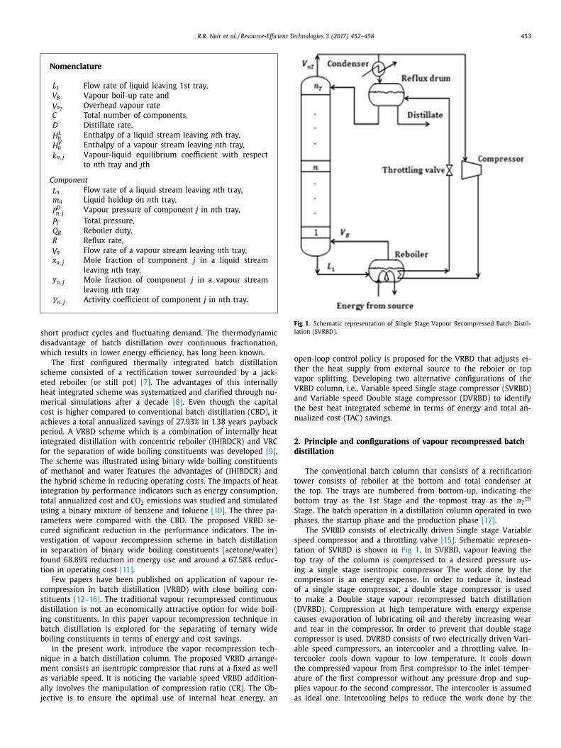
Fig 1. Schematic representation of Single Stage Vapour Recompressed Batch Distil-
lation (SVRBD).
o
t
v
V
a
t
n
2
d
t
t
b
S
p
s
t
t
i
c
o
t
(
c
a
c
a
t
t
a
p
a
Nomenclature
L 1 Flow rate of liquid leaving 1st tray,
V B Vapour boil-up rate and
V n T Overhead vapour rate
C Total number of components,
D Distillate rate,
H
L n Enthalpy of a liquid stream leaving n th tray,
H
V n Enthalpy of a vapour stream leaving n th tray,
k n, j Vapour-liquid equilibrium coefficient with respect
to n th tray and j th
Component
L n Flow rate of a liquid stream leaving n th tray,
m n Liquid holdup on n th tray,
P 0 n, j Vapour pressure of component j in n th tray,
P T Total pressure,
Q R Reboiler duty,
R Reflux rate,
V n Flow rate of a vapour stream leaving n th tray,
x n, j Mole fraction of component j in a liquid stream
leaving n th tray, y n, j Mole fraction of component j in a vapour stream
leaving n th tray γn, j Activity coefficient of component j in n th tray.
hort product cycles and fluctuating demand. The thermodynamic
isadvantage of batch distillation over continuous fractionation,
hich results in lower energy efficiency, has long been known.
The first configured thermally integrated batch distillation
cheme consisted of a rectification tower surrounded by a jack-
ted reboiler (or still pot) [7] . The advantages of this internally
eat integrated scheme was systematized and clarified through nu-
erical simulations after a decade [8] . Even though the capital
ost is higher compared to conventional batch distillation (CBD), it
chieves a total annualized savings of 27.93% in 1.38 years payback
eriod. A VRBD scheme which is a combination of internally heat
ntegrated distillation with concentric reboiler (IHIBDCR) and VRC
or the separation of wide boiling constituents was developed [9] .
he scheme was illustrated using binary wide boiling constituents
f methanol and water features the advantages of (IHIBDCR) and
he hybrid scheme in reducing operating costs. The impacts of heat
ntegration by performance indicators such as energy consumption,
otal annualized cost and CO 2 emissions was studied and simulated
sing a binary mixture of benzene and toluene [10] . The three pa-
ameters were compared with the CBD. The proposed VRBD se-
ured significant reduction in the performance indicators. The in-
estigation of vapour recompression scheme in batch distillation
n separation of binary wide boiling constituents (acetone/water)
ound 68.89% reduction in energy use and around a 67.58% reduc-
ion in operating cost [11] .
Few papers have been published on application of vapour re-
ompression in batch distillation (VRBD) with close boiling con-
tituents [12–16] . The traditional vapour recompressed continuous
istillation is not an economically attractive option for wide boil-
ng constituents. In this paper vapour recompression technique in
atch distillation is explored for the separating of ternary wide
oiling constituents in terms of energy and cost savings.
In the present work, introduce the vapor recompression tech-
ique in a batch distillation column. The proposed VRBD arrange-
ent consists an isentropic compressor that runs at a fixed as well
s variable speed. It is noticing the variable speed VRBD addition-
lly involves the manipulation of compression ratio (CR). The Ob-
ective is to ensure the optimal use of internal heat energy, an
pen-loop control policy is proposed for the VRBD that adjusts ei-
her the heat supply from external source to the reboier or top
apor splitting. Developing two alternative configurations of the
RBD column, i.e., Variable speed Single stage compressor (SVRBD)
nd Variable speed Double stage compressor (DVRBD) to identify
he best heat integrated scheme in terms of energy and total an-
ualized cost (TAC) savings.
. Principle and configurations of vapour recompressed batch
istillation
The conventional batch column that consists of a rectification
ower consists of reboiler at the bottom and total condenser at
he top. The trays are numbered from bottom-up, indicating the
ottom tray as the 1st Stage and the topmost tray as the n T th
tage. The batch operation in a distillation column operated in two
hases, the startup phase and the production phase [17] .
The SVRBD consists of electrically driven Single stage Variable
peed compressor and a throttling valve [15] . Schematic represen-
ation of SVRBD is shown in Fig 1 . In SVRBD, vapour leaving the
op tray of the column is compressed to a desired pressure us-
ng a single stage isentropic compressor The work done by the
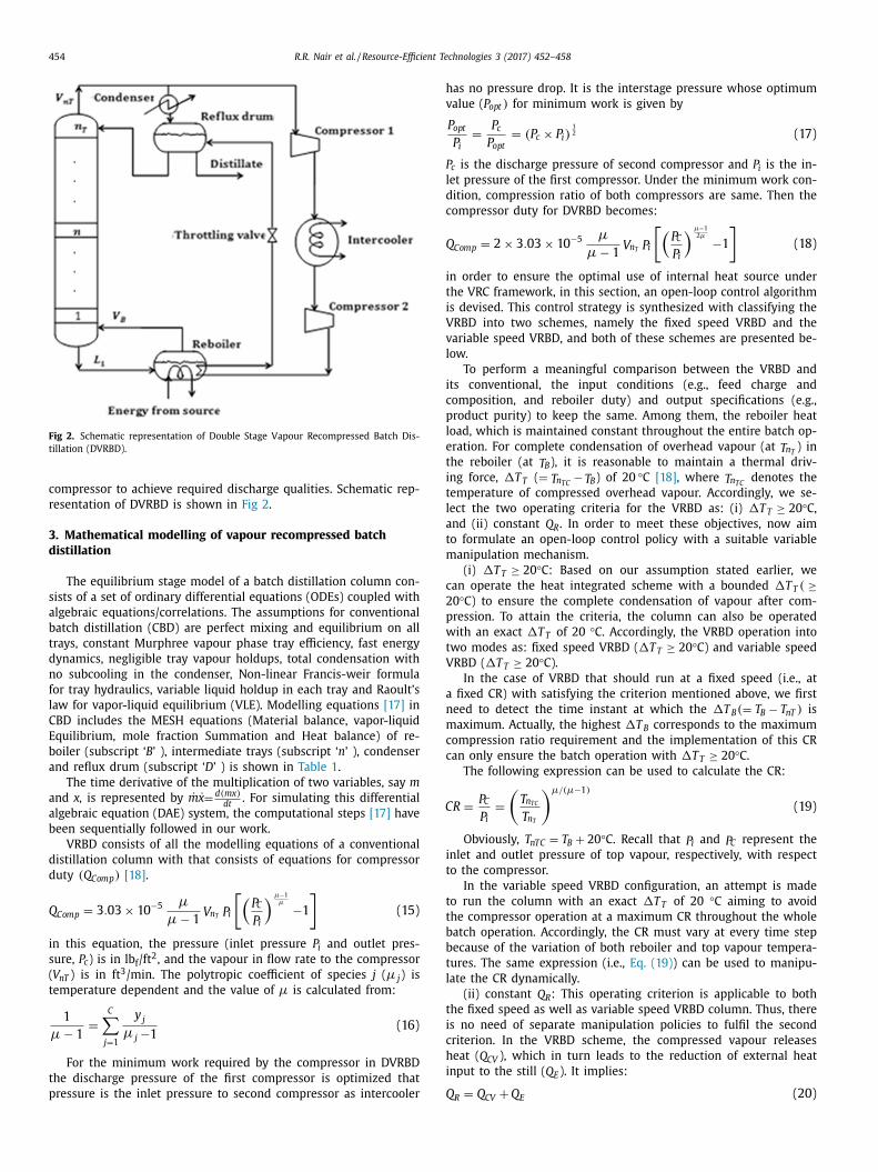
ompressor is an energy expense. In order to reduce it, instead
f a single stage compressor, a double stage compressor is used
o make a Double stage vapour recompressed batch distillation
DVRBD). Compression at high temperature with energy expense
auses evaporation of lubricating oil and thereby increasing wear
nd tear in the compressor. In order to prevent that double stage
ompressor is used. DVRBD consists of two electrically driven Vari-
ble speed compressors, an intercooler and a throttling valve. In-
ercooler cools down vapour to low temperature. It cools down
he compressed vapour from first compressor to the inlet temper-
ture of the first compressor without any pressure drop and sup-
lies vapour to the second compressor. The intercooler is assumed
s ideal one. Intercooling helps to reduce the work done by the
454 R.R. Nair et al. / Resource-Efficient Technologies 3 (2017) 452–458
Fig 2. Schematic representation of Double Stage Vapour Recompressed Batch Dis-
tillation (DVRBD).
h
v
P
l
d
c
Q
i
t
i
V
v
l
i
c
p
l
e
t
i
t
l
a
t
m
c
2
p
w
t
V
a
n
m
c
c
C
i
t
t
t
b
b
t
l
t
i
c
h
i
Q
compressor to achieve required discharge qualities. Schematic rep-
resentation of DVRBD is shown in Fig 2 .
3. Mathematical modelling of vapour recompressed batch
distillation
The equilibrium stage model of a batch distillation column con-
sists of a set of ordinary differential equations (ODEs) coupled with
algebraic equations/correlations. The assumptions for conventional
batch distillation (CBD) are perfect mixing and equilibrium on all
trays, constant Murphree vapour phase tray efficiency, fast energy
dynamics, negligible tray vapour holdups, total condensation with
no subcooling in the condenser, Non-linear Francis-weir formula
for tray hydraulics, variable liquid holdup in each tray and Raoult’s
law for vapor-liquid equilibrium (VLE). Modelling equations [17] in
CBD includes the MESH equations (Material balance, vapor-liquid
Equilibrium, mole fraction Summation and Heat balance) of re-
boiler (subscript ‘ B ’ ), intermediate trays (subscript ‘ n ’ ), condenser
and reflux drum (subscript ‘ D ’ ) is shown in Table 1 .
The time derivative of the multiplication of two variables, say m
and x, is represented by ˙ m ̇ x =
d( mx ) dt
. For simulating this differential
algebraic equation (DAE) system, the computational steps [17] have
been sequentially followed in our work.
VRBD consists of all the modelling equations of a conventional
distillation column with that consists of equations for compressor
duty ( Q Comp ) [18] .
Q Comp = 3 . 03 × 10
−5 μ
μ − 1
V n T P i
[(P C
P i
) μ−1 μ −1
](15)
in this equation, the pressure (inlet pressure P i and outlet pres-
sure, P c ) is in lb f /ft 2 , and the vapour in flow rate to the compressor
( V nT ) is in ft 3 /min. The polytropic coefficient of species j ( μ j ) is
temperature dependent and the value of μ is calculated from:
1
μ − 1
=
C ∑
j=1
y j μ j −1
(16)
For the minimum work required by the compressor in DVRBD
the discharge pressure of the first compressor is optimized that
pressure is the inlet pressure to second compressor as intercooler
as no pressure drop. It is the interstage pressure whose optimum
alue ( P opt ) for minimum work is given by
P opt
P i =
P c
P opt = ( P c × P i )
1 2 (17)
c is the discharge pressure of second compressor and P i is the in-
et pressure of the first compressor. Under the minimum work con-
ition, compression ratio of both compressors are same. Then the
ompressor duty for DVRBD becomes:
Comp = 2 × 3 . 03 × 10
−5 μ
μ − 1
V n T P i
[(P C
P i
) μ−1 2 μ −1
](18)
n order to ensure the optimal use of internal heat source under
he VRC framework, in this section, an open-loop control algorithm
s devised. This control strategy is synthesized with classifying the
RBD into two schemes, namely the fixed speed VRBD and the
ariable speed VRBD, and both of these schemes are presented be-
ow.
To perform a meaningful comparison between the VRBD and
ts conventional, the input conditions (e.g., feed charge and
omposition, and reboiler duty) and output specifications (e.g.,
roduct purity) to keep the same. Among them, the reboiler heat
oad, which is maintained constant throughout the entire batch op-
ration. For complete condensation of overhead vapour (at T n T ) in
he reboiler (at T B ), it is reasonable to maintain a thermal driv-
ng force, �T T ( = T n TC − T B ) of 20 °C [18] , where T n TC
denotes the
emperature of compressed overhead vapour. Accordingly, we se-
ect the two operating criteria for the VRBD as: (i) �T T ≥ 20 °C,
nd (ii) constant Q R . In order to meet these objectives, now aim
o formulate an open-loop control policy with a suitable variable
anipulation mechanism.
(i) �T T ≥ 20 °C: Based on our assumption stated earlier, we
an operate the heat integrated scheme with a bounded �T T ( ≥0 °C) to ensure the complete condensation of vapour after com-
ression. To attain the criteria, the column can also be operated
ith an exact �T T of 20 °C. Accordingly, the VRBD operation into
wo modes as: fixed speed VRBD ( �T T ≥ 20 °C) and variable speed
RBD ( �T T ≥ 20 °C).
In the case of VRBD that should run at a fixed speed (i.e., at
fixed CR) with satisfying the criterion mentioned above, we first
eed to detect the time instant at which the �T B (= T B − T nT ) is
aximum. Actually, the highest �T B corresponds to the maximum
ompression ratio requirement and the implementation of this CR
an only ensure the batch operation with �T T ≥ 20 °C.
The following expression can be used to calculate the CR:
R =
P C
P i =
(T n TC
T n T
)μ/ (μ−1)
(19)
Obviously, T nT C = T B + 20 °C. Recall that P i and P C represent the
nlet and outlet pressure of top vapour, respectively, with respect
o the compressor.
In the variable speed VRBD configuration, an attempt is made
o run the column with an exact �T T of 20 °C aiming to avoid
he compressor operation at a maximum CR throughout the whole
atch operation. Accordingly, the CR must vary at every time step
ecause of the variation of both reboiler and top vapour tempera-
ures. The same expression (i.e., Eq. (19) ) can be used to manipu-
ate the CR dynamically.
(ii) constant Q R : This operating criterion is applicable to both
he fixed speed as well as variable speed VRBD column. Thus, there
s no need of separate manipulation policies to fulfil the second
riterion. In the VRBD scheme, the compressed vapour releases
eat ( Q CV ), which in turn leads to the reduction of external heat
nput to the still ( Q E ). It implies:
= Q
+ Q
(20)
R CV E
R.R. Nair et al. / Resource-Efficient Technologies 3 (2017) 452–458 455
Table 1
Modelling equations in CBD includes the MESH equations.
Equation Equation Equation number
Reboiler (subscript ‘ B ’):
Total mole Balance ˙ m B = L 1 −V B = −D 1
Component mole Balance ˙ m B ˙ x B, j = L 1 x 1 , j −V B y B, j 2
Energy balance ˙ m B ˙ H
L
B = Q R + L 1 H L 1 −V B H
V B 3
Equilibrium
y B, j = k B, j x B, j =
γB, j P 0 B, j
P T x B, j 4
Summation C ∑
j=1
x D, j = 1 ; C ∑
j=1
y D, j = 1 5
Intermediate trays (subscript ‘ n ’):
Total mole balance ˙ m n = L n +1 + V n −1 − L n −V n 6
Component mole Balance ˙ m n ˙ x n, j = L n +1 x n +1 , j + V n −1 y n −1 , j − L n x n, j −V n y n, j 7
Energy balance ˙ m n ˙ H L
n = L n +1 H L n +1 + V n −1 H
V n −1 − L n H
L n −V n H
V n 8
Equilibrium
y n, j = k n, j x n, j =
γn, j P 0 n, j
P T x n, j 9
Summation C ∑
j=1
x D, j = 1 ; C ∑
j=1
y D, j = 1 10
Condenser and reflux drum (subscript ‘ D ’):
Total mole balance ˙ m D = V n T −R − D 11
Component mole Balance ˙ m D ˙ x D, j = V n T y n T , j −( R + D ) x D, j 12
Equilibrium
y D, j = k D, j x D, j =
γD, j P 0 D, j
P T x D, j 13
Summation C ∑
j=1
x D, j = 1 ; C ∑
j=1
y D, j = 1 14
t
t
t
r
Q
t
t
f
c
(
a
d
V
I
u
s
c
c
m
m
m
i
l
V
(
t
v
e
s
4
u
Table 2
Column parameters and specifications.
System hexanol/octanol/decanol
Total feed charge, kmol 40.0
Feed composition (startup), mol fract 0.5/0.4/0.1
Tray holdup in each tray (startup), kmol 0.125
Reflux drum holdup, kmol 0.1
Murphree vapour-phase tray efficiency, % 75
Heat input to the still pot, kJ/min 4400.0
Distillate rate (fixed), kmol/min 0.064
a
c
c
r
e
F
p
c
a
p
d
1
8
8
u
(
r
9
F
o
t
t
t
f
t
Because of the unsteady state characteristics of batch column,
he Q CV should vary with time. Under this circumstance, there are
wo possibilities arise as: Q CV > Q R and Q CV < Q R .
In the case ( Q CV > Q R ) , the latent heat ( λ) released by the
op vapour in the still is more than the heat required for liquid
eboiling. It is experienced that the use of this extra heat (i.e.,
CV − Q R ) does not necessarily improve the batch processing, par-
icularly when the setup is run with optimal Q R . Rather, it prolongs
he startup operation because of the reboiling of relatively heavier
raction by that extra heat. This fact clearly demonstrates the ne-
essity of overhead vapour ( V n T ) splitting so that a fraction of it
V n TC ) can exactly alter the heat required by the still pot (i.e., Q R )
nd the rest amount ( V n Ti ) can be directed to the overhead con-
enser. For this, the V n TC can be calculated as:
n TC =
Q R
λ(at T n TC )
(21)
Now, one can easily obtain the V n Ti by subtracting V n TC
from V n T .
t becomes clear that when Q CV > Q R , the VRBD requires to manip-
late the overhead vapour splitting.
In the case of ( Q CV < Q R ) , the heat available from internal
ource is not adequate to run the column with the same dynami-
al features. Therefore, the balance of the heat requirements of the
olumn (i.e., Q R − Q CV ) is supplied by steam (an external heating
edium) to the still. Obviously, in this case, the VRBD involves the
anipulation of steam flow rate ( m S ):
S λS = Q E = Q R − Q CV (22)
Where, the λS represents the latent heat of steam calculated at
ts temperature T S .
It is worth noticing that this open-loop control law is formu-
ated to compute a single manipulated variable for the fixed speed
RBD, i.e. either the vapor inflow rate to the compressor, V n TC
when Q CV > Q R ) or the auxiliary heat input to the still from an ex-
ernal source, Q E (or m S ) (when Q CV < Q R ). On the other hand, the
ariable speed scheme simultaneously adjusts the CR along with
ither the V n TC or the Q E . In present wok we have chosen variable
peed than fixed speed because it gives more energy savings.
. Results and discussion
In order to analyse the features of the proposed VRBD config-
ration, a simple example, separating a ternary mixture of hex-
nol, octanol and decanol is considered. We chose this system be-
ause it is a typical separation of compounds with wide boiling
onstituents. Initially the feed is charged in the reboiler, trays and
eflux drum. the proposed VRBD column are simulated in MatLab
nvironment with:
• a sampling instant of 0.0 0 01 min,
• a tolerance limit of 10 −4 for convergence
The column consists of 11 trays numbered from bottom to top.
eed is filled in the reboiler, trays and reflux drum. The operating
arameters and column specifications, summarized in Table 2 .
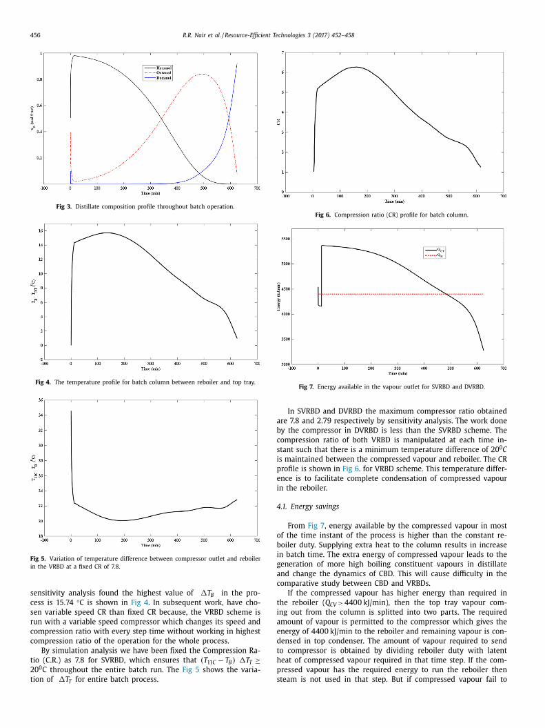
The hexanol composition in distillate reaches the pre-specified
oncentration of 98% (at 13 min), the distillate withdrawal for hex-
nol (production 1 phase) continues till average distillate com-
osition remains above the specified purity (98%). After the pro-
uction 1 phase, slop cut 1 phase starts (26 min), this slop cut
phase continues till composition of octanol in distillate reaches
0% (436 min). As the composition of octanol in distillate reaches
0% the production 2 phase starts. This production 2 phase contin-
es till the average composition of octanol in distillate reaches 80%
580 min). After the completion of production 2 phase, the column
uns till the average composition of decanol in reboiler reaches
8% (at 625 min). The distillate composition profile is shown in
ig 3 .
It is now necessary to determine what is the maximum value
f �T B , based on which the operating CR can be found out. For
his, we produce Fig 4 . that demonstrates the temperature profile
hroughout the batch operation. The difference between tempera-
ures of reboiler and top tray vapours �T B ( T B − T NT ) , is the driving
orce for the compressor. As �T B increases the compression ra-
io increases which increases the work done by the compressor. By
456 R.R. Nair et al. / Resource-Efficient Technologies 3 (2017) 452–458
Fig 3. Distillate composition profile throughout batch operation.
Fig 4. The temperature profile for batch column between reboiler and top tray.
Fig 5. Variation of temperature difference between compressor outlet and reboiler
in the VRBD at a fixed CR of 7.8.
Fig 6. Compression ratio (CR) profile for batch column.
Fig 7. Energy available in the vapour outlet for SVRBD and DVRBD.
a
b
c
s
i
p
e
i
4
o
b
i
g
a
c
t
i
a
e
d
t
h
p
s
sensitivity analysis found the highest value of �T B in the pro-
cess is 15.74 °C is shown in Fig 4 . In subsequent work, have cho-
sen variable speed CR than fixed CR because, the VRBD scheme is
run with a variable speed compressor which changes its speed and
compression ratio with every step time without working in highest
compression ratio of the operation for the whole process.
By simulation analysis we have been fixed the Compression Ra-
tio (C.R.) as 7.8 for SVRBD, which ensures that ( T 11 C − T B ) �T T ≥20 0 C throughout the entire batch run. The Fig 5 shows the varia-
tion of �T for entire batch process.
TIn SVRBD and DVRBD the maximum compressor ratio obtained
re 7.8 and 2.79 respectively by sensitivity analysis. The work done
y the compressor in DVRBD is less than the SVRBD scheme. The
ompression ratio of both VRBD is manipulated at each time in-
tant such that there is a minimum temperature difference of 20 0 C
s maintained between the compressed vapour and reboiler. The CR
rofile is shown in Fig 6 . for VRBD scheme. This temperature differ-
nce is to facilitate complete condensation of compressed vapour
n the reboiler.
.1. Energy savings
From Fig 7 , energy available by the compressed vapour in most
f the time instant of the process is higher than the constant re-
oiler duty. Supplying extra heat to the column results in increase
n batch time. The extra energy of compressed vapour leads to the
eneration of more high boiling constituent vapours in distillate
nd change the dynamics of CBD. This will cause difficulty in the
omparative study between CBD and VRBDs.
If the compressed vapour has higher energy than required in
he reboiler ( Q CV > 4400 kJ/min), then the top tray vapour com-
ng out from the column is splitted into two parts. The required
mount of vapour is permitted to the compressor which gives the
nergy of 4400 kJ/min to the reboiler and remaining vapour is con-
ensed in top condenser. The amount of vapour required to send
o compressor is obtained by dividing reboiler duty with latent
eat of compressed vapour required in that time step. If the com-
ressed vapour has the required energy to run the reboiler then
team is not used in that step. But if compressed vapour fail to
R.R. Nair et al. / Resource-Efficient Technologies 3 (2017) 452–458 457
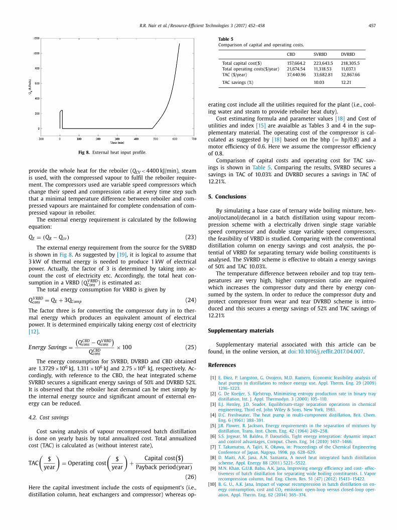
Fig 8. External heat input profile.
p
i
m
c
t
p
p
e
Q
i
3
p
c
s
Q
T
m
p
[
E
a
c
S
I
t
e
4
i
c
T
H
d
Table 5
Comparison of capital and operating costs.
CBD SVRBD DVRBD
Total capital cost($) 157,664.2 223,643.5 218,305.5
Total operating costs($/year) 21,674.54 11,318.53 11,037.1
TAC ($/year) 37,440.96 33,682.81 32,867.66
TAC savings (%) 10.03 12.21
e
i
u
p
c
m
o
i
s
1
5
a
p
s
t
d
t
a
o
p
w
s
p
d
1
S
f
R
[
rovide the whole heat for the reboiler ( Q CV < 4400 kJ/min), steam
s used, with the compressed vapour to fulfil the reboiler require-
ent. The compressors used are variable speed compressors which
hange their speed and compression ratio at every time step such
hat a minimal temperature difference between reboiler and com-
ressed vapours are maintained for complete condensation of com-
ressed vapour in reboiler.
The external energy requirement is calculated by the following
quation:
E = ( Q R − Q cv ) (23)
The external energy requirement from the source for the SVRBD
s shown in Fig 8 . As suggested by [19] , it is logical to assume that
kW of thermal energy is needed to produce 1 kW of electrical
ower. Actually, the factor of 3 is determined by taking into ac-
ount the cost of electricity etc. Accordingly, the total heat con-
umption in a VRBD ( Q
V RBD Cons ) is estimated as:
The total energy consumption for VRBD is given by
V RBD cons = Q E + 3 Q Comp (24)
he factor three is for converting the compressor duty in to ther-
al energy which produces an equivalent amount of electrical
ower. It is determined empirically taking energy cost of electricity
12] .
nergy Sa v ings =
(Q
CBD cons − Q
V RBD cons
)Q
CBD cons
× 100 (25)
The energy consumption for SVRBD, DVRBD and CBD obtained
re 1.3729 ×10 6 kJ, 1.311 ×10 6 kJ and 2.75 ×10 6 kJ, respectively. Ac-
ordingly, with reference to the CBD, the heat integrated scheme
VRBD secures a significant energy savings of 50% and DVRBD 52%.
t is observed that the reboiler heat demand can be met simply by
he internal energy source and significant amount of external en-
rgy can be reduced.
.2. Cost savings
Cost saving analysis of vapour recompressed batch distillation
s done on yearly basis by total annualized cost. Total annualized
ost (TAC) is calculated as (without interest rate),
AC
($
year
)= Operating cost
($
year
)+
Capital cost ($ )
Payback period ( year )
(26)
ere the capital investment include the costs of equipment’s (i.e.,
istillation column, heat exchangers and compressor) whereas op-
rating cost include all the utilities required for the plant (i.e., cool-
ng water and steam to provide reboiler heat duty).
Cost estimating formula and parameter values [18] and Cost of
tilities and index [15] are avaialble as Tables 3 and 4 in the sup-
lementary material. The operating cost of the compressor is cal-
ulated as suggested by [18] based on the bhp ( = hp/0.8) and a
otor efficiency of 0.6. Here we assume the compressor efficiency
f 0.8.
Comparison of capital costs and operating cost for TAC sav-
ngs is shown in Table 5 . Comparing the results, SVRBD secures a
avings in TAC of 10.03% and DVRBD secures a savings in TAC of
2.21%.
. Conclusions
By simulating a base case of ternary wide boiling mixture, hex-
nol/octanol/decanol in a batch distillation using vapour recom-
ression scheme with a electrically driven single stage variable
peed compressor and double stage variable speed compressors,
he feasibility of VRBD is studied. Comparing with the conventional
istillation column on energy savings and cost analysis, the po-
ential of VRBD for separating ternary wide boiling constituents is
nalysed. The SVRBD scheme is effective to obtain a energy savings
f 50% and TAC 10.03%.
The temperature difference between reboiler and top tray tem-
eratures are very high, higher compression ratio are required
hich increases the compressor duty and there by energy con-
umed by the system. In order to reduce the compressor duty and
rotect compressor from wear and tear DVRBD scheme is intro-
uced and this secures a energy savings of 52% and TAC savings of
2.21%
upplementary materials
Supplementary material associated with this article can be
ound, in the online version, at doi:10.1016/j.reffit.2017.04.007 .
eferences
[1] E. Diez , P. Langston , G. Ovojero , M.D. Ramero , Economic feasibility analysis of
heat pumps in distillation to reduce energy use, Appl. Therm. Eng. 29 (2009)
1216–1223 . [2] G. De Koeijer , S. Kjelstrup , Minimizing entropy production rate in binary tray
distillation, Int. J. Appl. Thermodyn. 3 (20 0 0) 105–110 . [3] E.J. Henley , J.D. Seader , Equilibrium-stage separation operations in chemical
engineering, Third ed, John Wiley & Sons, New York, 1981 . [4] D.C. Freshwater , The heat pump in multi-component distillation, Brit. Chem.
Eng. 6 (1961) 388–391 .
[5] J.R. Flower , R. Jackson , Energy requirements in the separation of mixtures bydistillation, Trans. Inst. Chem. Eng. 42 (1964) 249–258 .
[6] S.S. Jogwar , M. Baldea , P. Daoutidis , Tight energy integration: dynamic impactand control advantages, Comput. Chem. Eng. 34 (2010) 1457–1466 .
[7] T. Takamatsu , A. Tajiri , K. Okawa , in: Proceedings of the Chemical EngineeringConference of Japan, Nagoya, 1998, pp. 628–629 .
[8] D. Maiti , A.K. Jana , A.N. Samanta , A novel heat integrated batch distillationscheme, Appl. Energy 88 (2011) 5221–5522 .
[9] M.N. Khan , G.U.B. Babu , A.K. Jana , Improving energy efficiency and cost- effec-
tiveness of batch distillation for separating wide boiling constituents. I. Vaporrecompression column, Ind. Eng. Chem. Res. 51 (47) (2012) 15413–15422 .
10] B. G. U. , A.K. Jana , Impact of vapour recompression in batch distillation on en-ergy consumption, cost and CO 2 emission: open-loop versus closed-loop oper-
ation, Appl. Therm. Eng. 62 (2014) 365–374 .

458 R.R. Nair et al. / Resource-Efficient Technologies 3 (2017) 452–458
[11] A.K. Jana , A. Mane , Heat pump assisted reactive distillation: wide boiling mix-ture, AIChE J. 57 (2011) 3233–3237 .
[12] G.U.B. Babu , R. Aditya , A.K. Jana , Economic feasibility of a novel energy efficientmiddle vessel batch distillation to reduce energy use, Energy 45 (1) (2012)
626–633 . [13] G.U.B. Babu , E.K. Pal , A.K. Jana , An adaptive vapor recompression scheme for a
ternary batch distillation with a side withdrawal, Ind. Eng. Chem. Res. 51 (13)(2012) 4 990–4 997 .
[14] D. Maiti , A.K. Jana , A.N. Samanta , Intensified thermal integration in batch reac-
tive distillation, Appl. Energy 103 (2013) 290–297 . [15] K. Johri , G.U.B. Babu , A.K. Jana , Performance investigation of a variable speed
vapour recompression reactive batch rectifier, AIChE J. 57 (2011) 3238–3242 .
[16] M.N. Khan , D. Maiti , A.K. Jana , Improving energy efficiency and cost- effective-ness of batch distillation for separating wide boiling constituents. II: internal
versus external heat integration, Chem. Eng. Process. 72 (2013) 122–129 . [17] A.K. Jana , Chemical Process Modelling and Computer Simulation, second ed.,
Prentice-Hall, New Delhi, 2011 . [18] J.M. Douglas , Conceptual Design of Chemical Processes, first ed., McGraw-Hill,
New York, 1988 . [19] K. Iwakabe , M. Nakaiwa , K. Huang , T. Nakanishi , A. Rosjorde , T. v Ohmori ,
A. Endo , T. Yamamoto , Energy saving in multicomponent separation using an
internally heat integrated distillation column (HIDiC), Appl. Therm. Eng. 26(2006) 1362–1368 .