Embed Size (px)
Citation preview
8/3/2019 Vapour Barriers
http://slidepdf.com/reader/full/vapour-barriers 1/23
Confusion on the issue of vapor barriers and air barriers is common. The confusion arises because air often holds a great deal of moisture in the vapor
form. When this air moves from location to location due to an air pressure difference, the vapor moves with it. This is a type of migration of water
vapor. In the strictest sense air barriers are also vapor barriers when they control the transport of moisture-laden air.
An excellent discussion about the differences between vapor barriers and air barriers can be found inQuirrouette (1985).
Vapor barriers are also a cold climate artifact that have diffused into other climates more from ignorance than need. The history of cold
climate vapor barriers itself is a story based more on personalities than physics. Rose (1997) regales readers of this history. It is
frightening indeed that construction practices can be so dramatically influenced by so little research and reassuring indeed that the
inherent robustness of most building assemblies has been able to tolerate such foolishness.
So What is The Problem?
Incorrect use of vapor barriers is leading to an increase in moisture related problems. Vapor barriers were originally intended to prevent
assemblies from getting wet. However, they often prevent assemblies from drying. Vapor barriers installed on the interior of assemblies
prevent assemblies from drying inward. This can be a problem in any air-conditioned enclosure. This can be a problem in any below
grade space. This can be a problem when there is also a vapor barrier on the exterior. This can be a problem where brick is installed
over building paper and vapor permeable sheathing.
What Do We Really Want to Do?
Two seemingly simple requirements for building enclosures bedevil engineers and architects almost endlessly:
• keep water out
• let water out if it gets in
Water can come in several phases: liquid, solid, vapor and adsorbed. The liquid phase as rain and ground water has driven everyone
crazy for hundreds of years but can be readily understood - drain everything and remember the humble flashing. The solid phase also
drives everyone crazy when we have to shovel it or melt it, but at least most professionals understand the related building problems (ice
damming, frost heave, freeze-thaw damage). But the vapor phase is in a class of craziness all by itself. We will conveniently ignore the
adsorbed phase and leave it for someone else to deal with. Note that adsorbed water is different than absorbed water (see Kumaran,Mitalas & Bomberg, 1994).
The fundamental principle of control of water in the liquid form is to drain it out if it gets in – and let us make it perfectly clear – it will get
in if you build where it rains or if you put your building in the ground where there is water in the ground. This is easy to understand,
logical, with a long historical basis.
The fundamental principle of control of water in the solid form is to not let it get solid and if it does – give it space or if it is solid not let it
get liquid and if it does drain it away before it can get solid again. This is a little more difficult to understand, but logical and based on
solid research. Examples of this principle include the use of air entrained concrete to control freeze-thaw damage and the use of attic
venting to provide cold roof decks to control ice damming.
The fundamental principle of control of water in the vapor form is to keep it out and to let it out if it gets in. Simple right? No chance. It
gets complicated because sometimes the best strategies to keep water vapor out also trap water vapor in. This can be a real problem if
the assemblies start out wet because of rain or the use of wet materials.
It gets even more complicated because of climate. In general water vapor moves from the warm side of building assemblies to the cold
side of building assemblies. This is simple to understand, except we have trouble deciding what side of a wall is the cold or warm side.
Logically, this means we need different strategies for different climates. We also have to take into account differences between summer
and winter.
Finally, complications arise when materials can store water. This can be both good and bad. A cladding system such as a brick veneer
can act as a reservoir after a rainstorm and significantly complicate wall design. Alternatively, wood framing or masonry can act as a
hygric buffer absorbing water lessening moisture shocks.
What is required is to define vapor control measures on a more regional climatic basis and to define the vapor control measures more
precisely.
8/3/2019 Vapour Barriers
http://slidepdf.com/reader/full/vapour-barriers 2/23
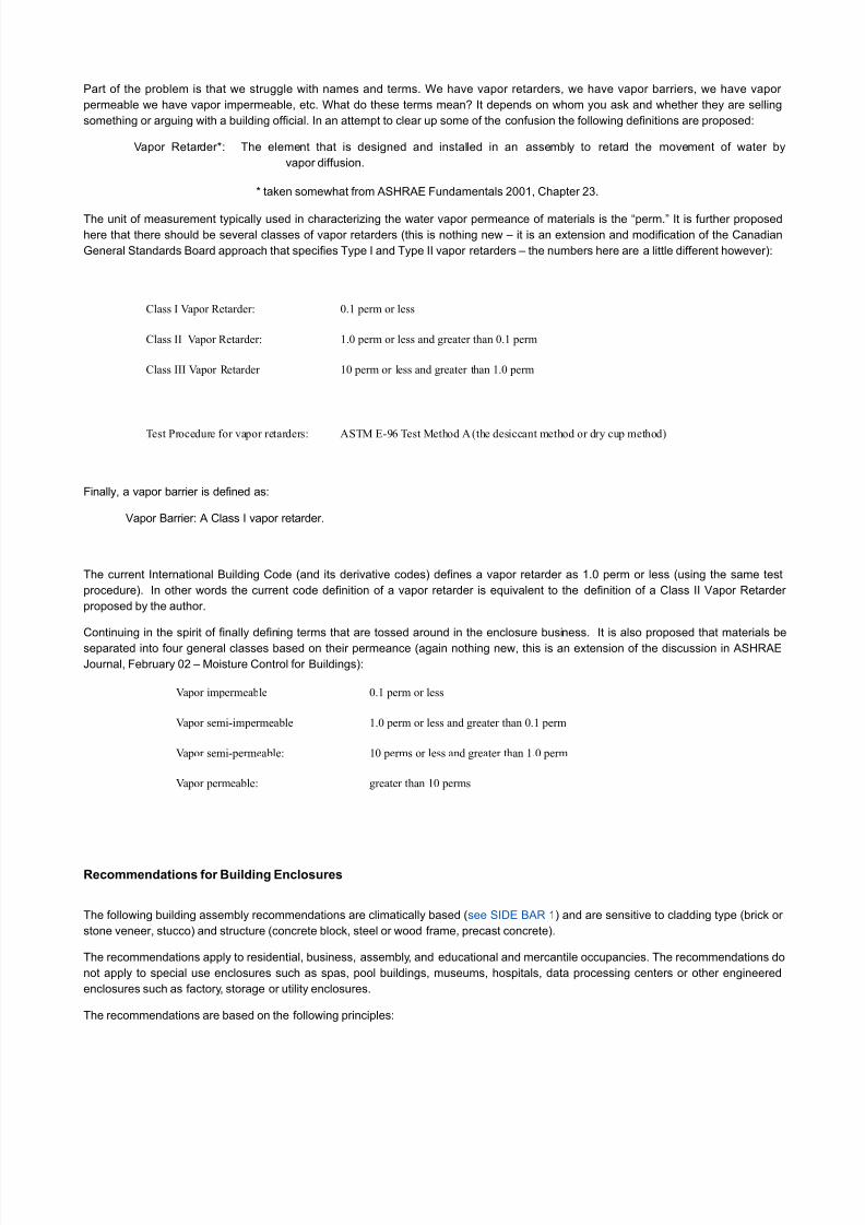
Part of the problem is that we struggle with names and terms. We have vapor retarders, we have vapor barriers, we have vapor
permeable we have vapor impermeable, etc. What do these terms mean? It depends on whom you ask and whether they are selling
something or arguing with a building official. In an attempt to clear up some of the confusion the following definitions are proposed:
Vapor Retarder*: The element that is designed and installed in an assembly to retard the movement of water by
vapor diffusion.
* taken somewhat from ASHRAE Fundamentals 2001, Chapter 23.
The unit of measurement typically used in characterizing the water vapor permeance of materials is the “perm.” It is further proposed
here that there should be several classes of vapor retarders (this is nothing new – it is an extension and modification of the Canadian
General Standards Board approach that specifies Type I and Type II vapor retarders – the numbers here are a little different however):
Class I Vapor Retarder: 0.1 perm or less
Class II Vapor Retarder: 1.0 perm or less and greater than 0.1 perm
Class III Vapor Retarder 10 perm or less and greater than 1.0 perm
Test Procedure for vapor retarders: ASTM E-96 Test Method A (the desiccant method or dry cup method)
Finally, a vapor barrier is defined as:
Vapor Barrier: A Class I vapor retarder.
The current International Building Code (and its derivative codes) defines a vapor retarder as 1.0 perm or less (using the same test
procedure). In other words the current code definition of a vapor retarder is equivalent to the definition of a Class II Vapor Retarder
proposed by the author.
Continuing in the spirit of finally defining terms that are tossed around in the enclosure business. It is also proposed that materials be
separated into four general classes based on their permeance (again nothing new, this is an extension of the discussion in ASHRAE
Journal, February 02 – Moisture Control for Buildings):
Vapor impermeable 0.1 perm or less
Vapor semi-impermeable 1.0 perm or less and greater than 0.1 perm
Vapor semi-permeable: 10 perms or less and greater than 1.0 perm
Vapor permeable: greater than 10 perms
Recommendations for Building Enclosures
The following building assembly recommendations are climatically based (see SIDE BAR 1) and are sensitive to cladding type (brick or
stone veneer, stucco) and structure (concrete block, steel or wood frame, precast concrete).
The recommendations apply to residential, business, assembly, and educational and mercantile occupancies. The recommendations do
not apply to special use enclosures such as spas, pool buildings, museums, hospitals, data processing centers or other engineered
enclosures such as factory, storage or utility enclosures.
The recommendations are based on the following principles:
8/3/2019 Vapour Barriers
http://slidepdf.com/reader/full/vapour-barriers 3/23
• Avoidance of using vapor barriers where vapor retarders will provide satisfactory performance. Avoidance of using vapor
retarders where vapor permeable materials will provide satisfactory performance. Thereby encouraging drying mechanisms
over wetting prevention mechanisms.
• Avoidance of the installation of vapor barriers on both sides of assemblies – i.e. “double vapor barriers” in order to facilitate
assembly drying in at least one direction.
• Avoidance of the installation of vapor barriers such as polyethylene vapor barriers, foil faced batt insulation and reflective radiant
barrier foil insulation on the interior of air-conditioned assemblies – a practice that has been linked with moldy buildings(Lstiburek, 2002).
• Avoidance of the installation of vinyl wall coverings on the inside of air-conditioned assemblies – a practice that has been linked
with moldy buildings (Lstiburek, 1993).
• Enclosures are ventilated meeting ASHRAE Standard 62.2 or 62.1.
Each of the recommended building assemblies were evaluated using dynamic hygrothermal modeling. The moisture content of building
materials that comprise the building assemblies all remained below the equilibrium moisture content the materials as specified in
ASHRAE 160 P under this evaluation approach. Interior air conditions and exterior air conditions as specified by ASHRAE 160 P were
used. WUFI was used as the modeling program (Kunzel, 1999).
More significantly, each of the recommended building assemblies have been found by the author to provide satisfactory performance
under the limitations noted. Satisfactory performance is defined as no moisture problems reported or observed over at least a 10-year
period.
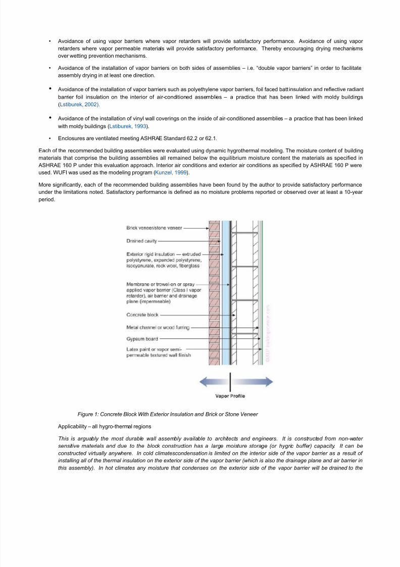
Figure 1: Concrete Block With Exterior Insulation and Brick or Stone Veneer
Applicability – all hygro-thermal regions
This is arguably the most durable wall assembly available to architects and engineers. It is constructed from non-water
sensitive materials and due to the block construction has a large moisture storage (or hygric buffer) capacity. It can be
constructed virtually anywhere. In cold climatescondensation is limited on the interior side of the vapor barrier as a result of
installing all of the thermal insulation on the exterior side of the vapor barrier (which is also the drainage plane and air barrier in
this assembly). In hot climates any moisture that condenses on the exterior side of the vapor barrier will be drained to the
8/3/2019 Vapour Barriers
http://slidepdf.com/reader/full/vapour-barriers 4/23
exterior since the vapor barrier is also a drainage plane. This wall assembly will dry from the vapor barrier inwards and will dry
from the vapor barrier outwards.
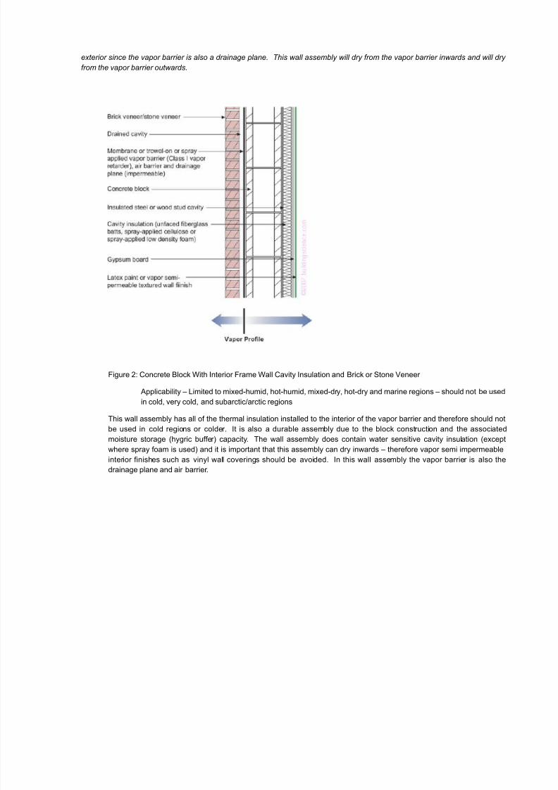
Figure 2: Concrete Block With Interior Frame Wall Cavity Insulation and Brick or Stone Veneer
Applicability – Limited to mixed-humid, hot-humid, mixed-dry, hot-dry and marine regions – should not be used
in cold, very cold, and subarctic/arctic regions
This wall assembly has all of the thermal insulation installed to the interior of the vapor barrier and therefore should not
be used in cold regions or colder. It is also a durable assembly due to the block construction and the associated
moisture storage (hygric buffer) capacity. The wall assembly does contain water sensitive cavity insulation (except
where spray foam is used) and it is important that this assembly can dry inwards – therefore vapor semi impermeable
interior finishes such as vinyl wall coverings should be avoided. In this wall assembly the vapor barrier is also the
drainage plane and air barrier.
8/3/2019 Vapour Barriers
http://slidepdf.com/reader/full/vapour-barriers 5/23
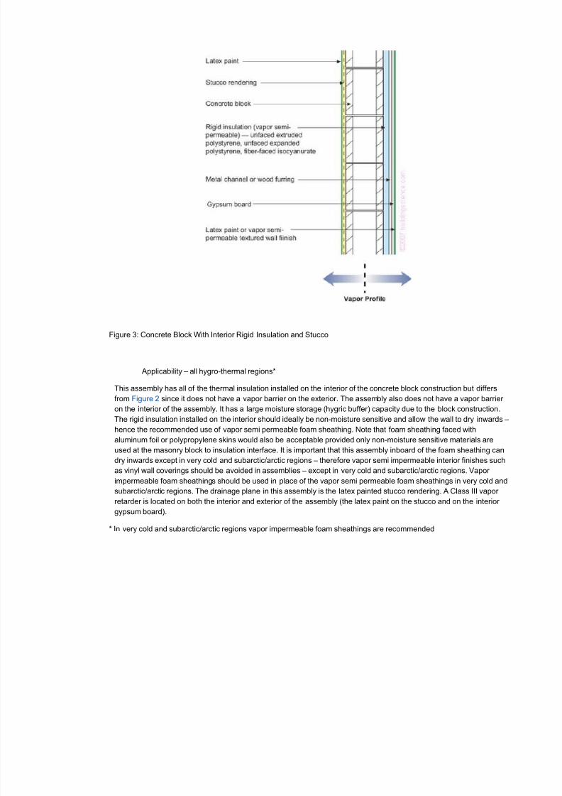
Figure 3: Concrete Block With Interior Rigid Insulation and Stucco
Applicability – all hygro-thermal regions*
This assembly has all of the thermal insulation installed on the interior of the concrete block construction but differs
from Figure 2 since it does not have a vapor barrier on the exterior. The assembly also does not have a vapor barrier
on the interior of the assembly. It has a large moisture storage (hygric buffer) capacity due to the block construction.
The rigid insulation installed on the interior should ideally be non-moisture sensitive and allow the wall to dry inwards –hence the recommended use of vapor semi permeable foam sheathing. Note that foam sheathing faced with
aluminum foil or polypropylene skins would also be acceptable provided only non-moisture sensitive materials are
used at the masonry block to insulation interface. It is important that this assembly inboard of the foam sheathing can
dry inwards except in very cold and subarctic/arctic regions – therefore vapor semi impermeable interior finishes such
as vinyl wall coverings should be avoided in assemblies – except in very cold and subarctic/arctic regions. Vapor
impermeable foam sheathings should be used in place of the vapor semi permeable foam sheathings in very cold and
subarctic/arctic regions. The drainage plane in this assembly is the latex painted stucco rendering. A Class III vapor
retarder is located on both the interior and exterior of the assembly (the latex paint on the stucco and on the interior
gypsum board).
* In very cold and subarctic/arctic regions vapor impermeable foam sheathings are recommended
8/3/2019 Vapour Barriers
http://slidepdf.com/reader/full/vapour-barriers 6/23
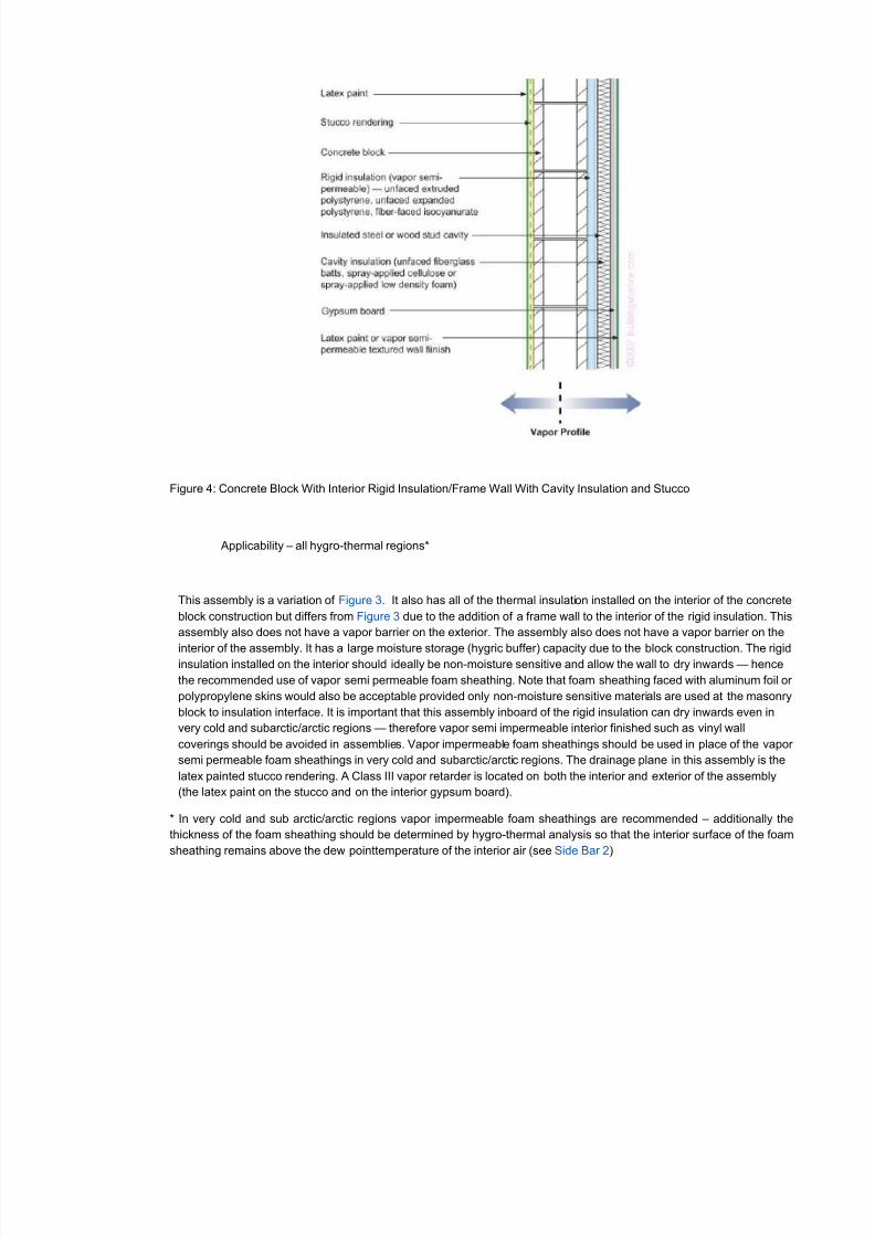
Figure 4: Concrete Block With Interior Rigid Insulation/Frame Wall With Cavity Insulation and Stucco
Applicability – all hygro-thermal regions*
This assembly is a variation of Figure 3. It also has all of the thermal insulation installed on the interior of the concrete
block construction but differs from Figure 3 due to the addition of a frame wall to the interior of the rigid insulation. This
assembly also does not have a vapor barrier on the exterior. The assembly also does not have a vapor barrier on the
interior of the assembly. It has a large moisture storage (hygric buffer) capacity due to the block construction. The rigidinsulation installed on the interior should ideally be non-moisture sensitive and allow the wall to dry inwards — hence
the recommended use of vapor semi permeable foam sheathing. Note that foam sheathing faced with aluminum foil or
polypropylene skins would also be acceptable provided only non-moisture sensitive materials are used at the masonry
block to insulation interface. It is important that this assembly inboard of the rigid insulation can dry inwards even in
very cold and subarctic/arctic regions — therefore vapor semi impermeable interior finished such as vinyl wall
coverings should be avoided in assemblies. Vapor impermeable foam sheathings should be used in place of the vapor
semi permeable foam sheathings in very cold and subarctic/arctic regions. The drainage plane in this assembly is the
latex painted stucco rendering. A Class III vapor retarder is located on both the interior and exterior of the assembly
(the latex paint on the stucco and on the interior gypsum board).
* In very cold and sub arctic/arctic regions vapor impermeable foam sheathings are recommended – additionally the
thickness of the foam sheathing should be determined by hygro-thermal analysis so that the interior surface of the foam
sheathing remains above the dew pointtemperature of the interior air (see Side Bar 2)
8/3/2019 Vapour Barriers
http://slidepdf.com/reader/full/vapour-barriers 7/23
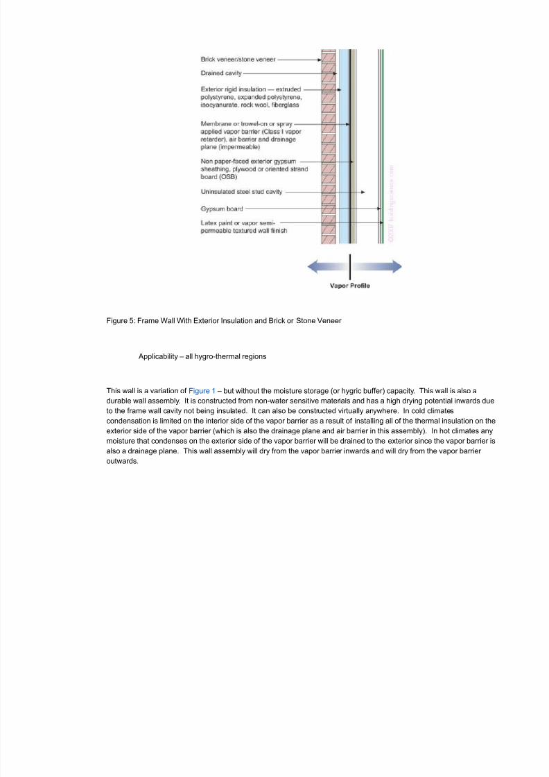
Figure 5: Frame Wall With Exterior Insulation and Brick or Stone Veneer
Applicability – all hygro-thermal regions
This wall is a variation of Figure 1 – but without the moisture storage (or hygric buffer) capacity. This wall is also a
durable wall assembly. It is constructed from non-water sensitive materials and has a high drying potential inwards due
to the frame wall cavity not being insulated. It can also be constructed virtually anywhere. In cold climates
condensation is limited on the interior side of the vapor barrier as a result of installing all of the thermal insulation on the
exterior side of the vapor barrier (which is also the drainage plane and air barrier in this assembly). In hot climates any
moisture that condenses on the exterior side of the vapor barrier will be drained to the exterior since the vapor barrier is
also a drainage plane. This wall assembly will dry from the vapor barrier inwards and will dry from the vapor barrier
outwards.
8/3/2019 Vapour Barriers
http://slidepdf.com/reader/full/vapour-barriers 8/23
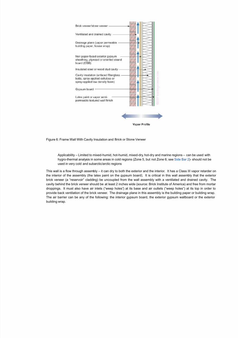
Figure 6: Frame Wall With Cavity Insulation and Brick or Stone Veneer
Applicability – Limited to mixed-humid, hot-humid, mixed-dry, hot-dry and marine regions – can be used with
hygro-thermal analysis in some areas in cold regions (Zone 5, but not Zone 6; see Side Bar 2)- should not be
used in very cold and subarctic/arctic regions
This wall is a flow through assembly – it can dry to both the exterior and the interior. It has a Class III vapor retarder on
the interior of the assembly (the latex paint on the gypsum board). It is critical in this wall assembly that the exterior
brick veneer (a “reservoir” cladding) be uncoupled from the wall assembly with a ventilated and drained cavity. The
cavity behind the brick veneer should be at least 2 inches wide (source: Brick Institute of America) and free from mortar
droppings. It must also have air inlets (“weep holes”) at its base and air outlets (“weep holes”) at its top in order to
provide back ventilation of the brick veneer. The drainage plane in this assembly is the building paper or building wrap.
The air barrier can be any of the following: the interior gypsum board, the exterior gypsum wallboard or the exterior
building wrap.
8/3/2019 Vapour Barriers
http://slidepdf.com/reader/full/vapour-barriers 9/23
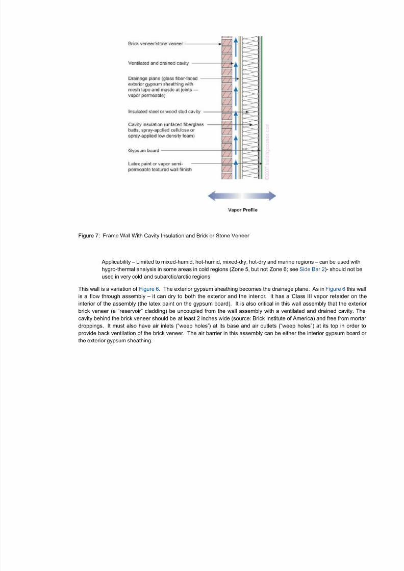
Figure 7: Frame Wall With Cavity Insulation and Brick or Stone Veneer
Applicability – Limited to mixed-humid, hot-humid, mixed-dry, hot-dry and marine regions – can be used with
hygro-thermal analysis in some areas in cold regions (Zone 5, but not Zone 6; see Side Bar 2)- should not be
used in very cold and subarctic/arctic regions
This wall is a variation of Figure 6. The exterior gypsum sheathing becomes the drainage plane. As in Figure 6 this wall
is a flow through assembly – it can dry to both the exterior and the interior. It has a Class III vapor retarder on the
interior of the assembly (the latex paint on the gypsum board). It is also critical in this wall assembly that the exterior
brick veneer (a “reservoir” cladding) be uncoupled from the wall assembly with a ventilated and drained cavity. The
cavity behind the brick veneer should be at least 2 inches wide (source: Brick Institute of America) and free from mortar
droppings. It must also have air inlets (“weep holes”) at its base and air outlets (“weep holes”) at its top in order to
provide back ventilation of the brick veneer. The air barrier in this assembly can be either the interior gypsum board or
the exterior gypsum sheathing.
8/3/2019 Vapour Barriers
http://slidepdf.com/reader/full/vapour-barriers 10/23
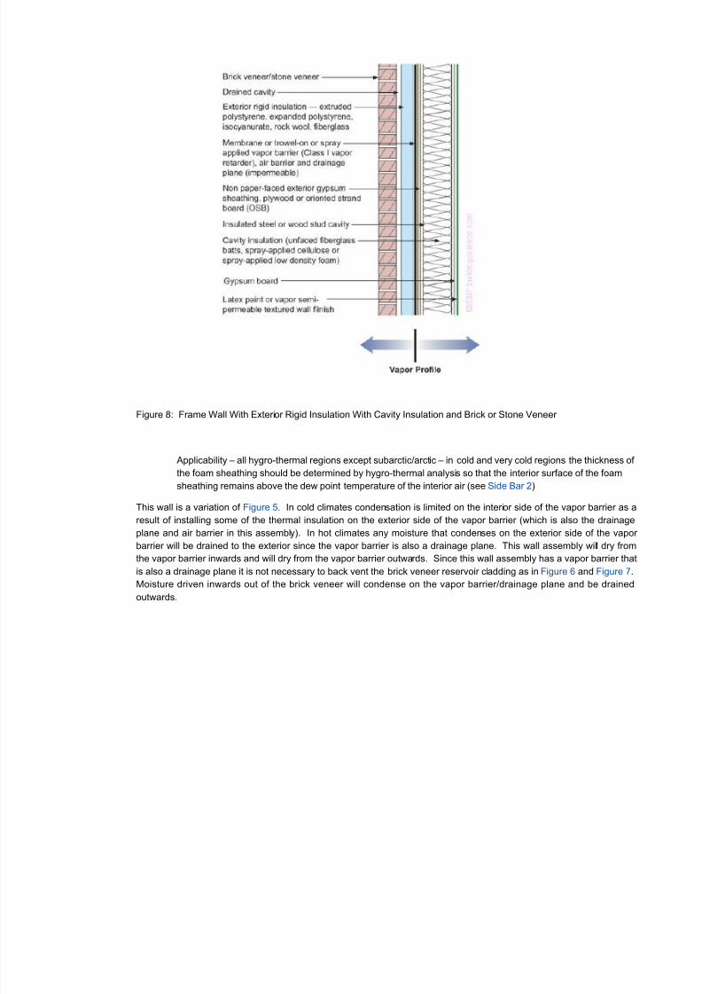
Figure 8: Frame Wall With Exterior Rigid Insulation With Cavity Insulation and Brick or Stone Veneer
Applicability – all hygro-thermal regions except subarctic/arctic – in cold and very cold regions the thickness of
the foam sheathing should be determined by hygro-thermal analysis so that the interior surface of the foam
sheathing remains above the dew point temperature of the interior air (see Side Bar 2)
This wall is a variation of Figure 5. In cold climates condensation is limited on the interior side of the vapor barrier as a
result of installing some of the thermal insulation on the exterior side of the vapor barrier (which is also the drainageplane and air barrier in this assembly). In hot climates any moisture that condenses on the exterior side of the vapor
barrier will be drained to the exterior since the vapor barrier is also a drainage plane. This wall assembly will dry from
the vapor barrier inwards and will dry from the vapor barrier outwards. Since this wall assembly has a vapor barrier that
is also a drainage plane it is not necessary to back vent the brick veneer reservoir cladding as in Figure 6 and Figure 7.
Moisture driven inwards out of the brick veneer will condense on the vapor barrier/drainage plane and be drained
outwards.
8/3/2019 Vapour Barriers
http://slidepdf.com/reader/full/vapour-barriers 11/23
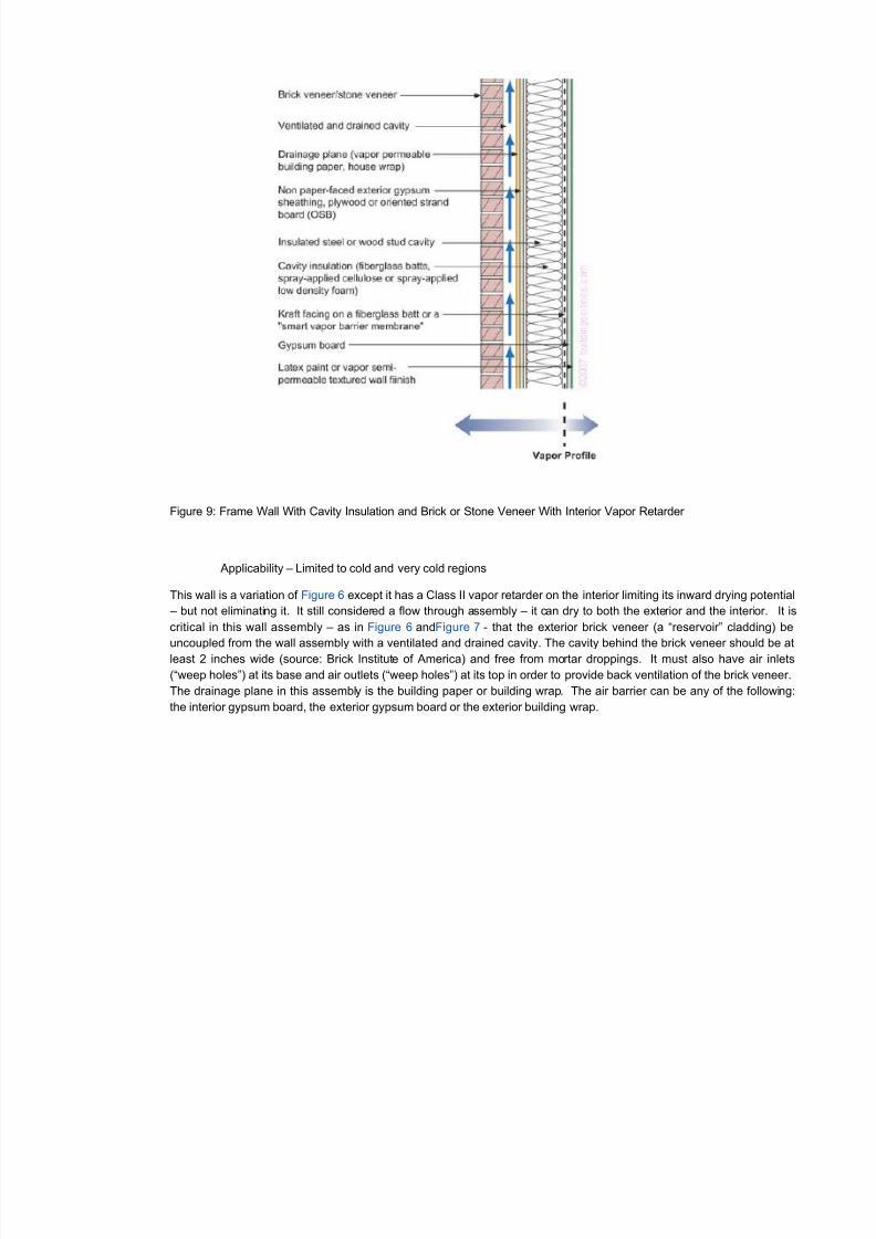
Figure 9: Frame Wall With Cavity Insulation and Brick or Stone Veneer With Interior Vapor Retarder
Applicability – Limited to cold and very cold regions
This wall is a variation of Figure 6 except it has a Class II vapor retarder on the interior limiting its inward drying potential
– but not eliminating it. It still considered a flow through assembly – it can dry to both the exterior and the interior. It is
critical in this wall assembly – as in Figure 6 andFigure 7 - that the exterior brick veneer (a “reservoir” cladding) be
uncoupled from the wall assembly with a ventilated and drained cavity. The cavity behind the brick veneer should be at
least 2 inches wide (source: Brick Institute of America) and free from mortar droppings. It must also have air inlets
(“weep holes”) at its base and air outlets (“weep holes”) at its top in order to provide back ventilation of the brick veneer.
The drainage plane in this assembly is the building paper or building wrap. The air barrier can be any of the following:
the interior gypsum board, the exterior gypsum board or the exterior building wrap.
8/3/2019 Vapour Barriers
http://slidepdf.com/reader/full/vapour-barriers 12/23
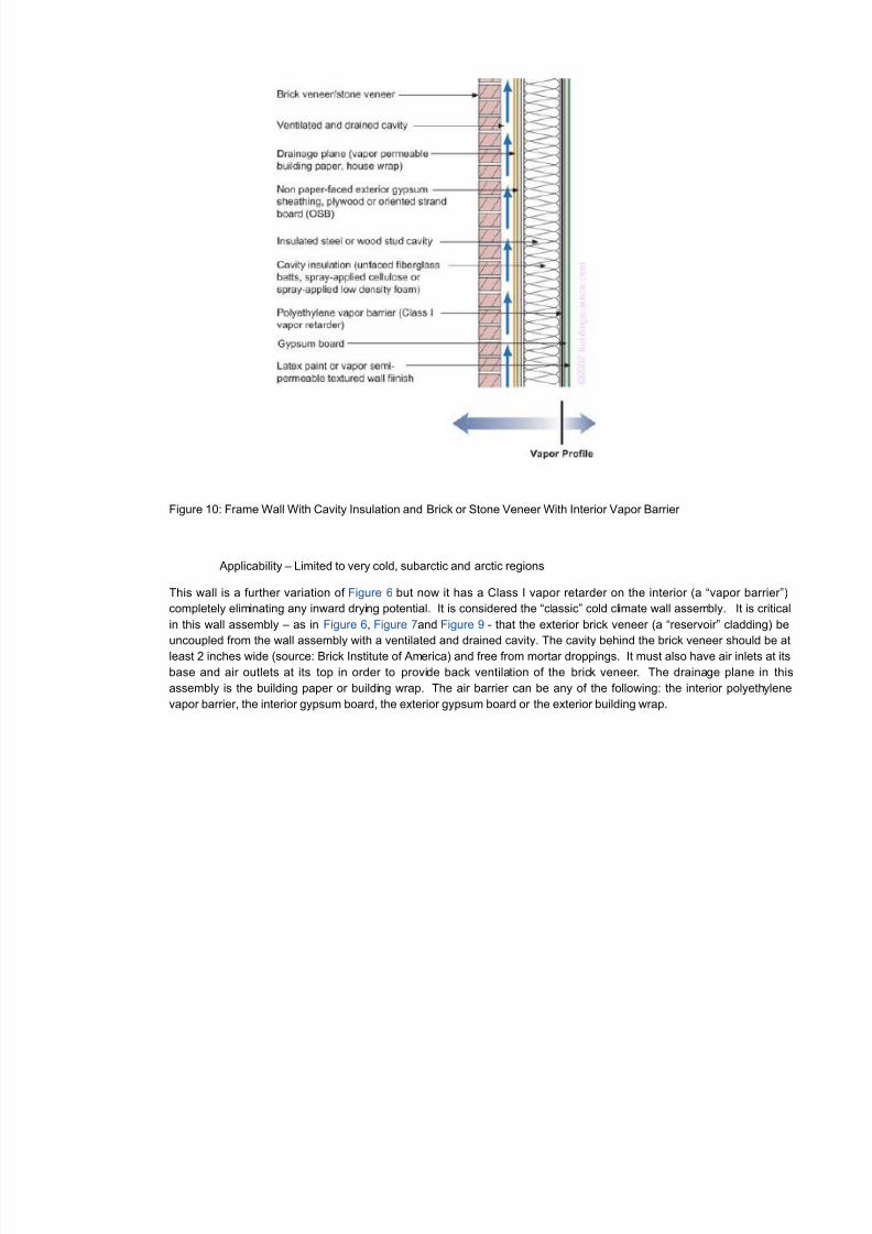
Figure 10: Frame Wall With Cavity Insulation and Brick or Stone Veneer With Interior Vapor Barrier
Applicability – Limited to very cold, subarctic and arctic regions
This wall is a further variation of Figure 6 but now it has a Class I vapor retarder on the interior (a “vapor barrier”)
completely eliminating any inward drying potential. It is considered the “classic” cold climate wall assembly. It is critical
in this wall assembly – as in Figure 6, Figure 7and Figure 9 - that the exterior brick veneer (a “reservoir” cladding) be
uncoupled from the wall assembly with a ventilated and drained cavity. The cavity behind the brick veneer should be at
least 2 inches wide (source: Brick Institute of America) and free from mortar droppings. It must also have air inlets at its
base and air outlets at its top in order to provide back ventilation of the brick veneer. The drainage plane in this
assembly is the building paper or building wrap. The air barrier can be any of the following: the interior polyethylene
vapor barrier, the interior gypsum board, the exterior gypsum board or the exterior building wrap.
8/3/2019 Vapour Barriers
http://slidepdf.com/reader/full/vapour-barriers 13/23
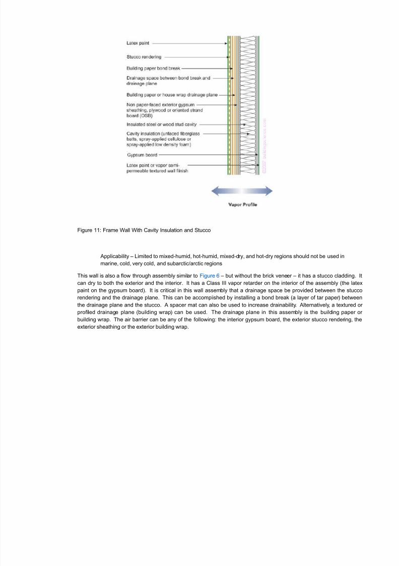
Figure 11: Frame Wall With Cavity Insulation and Stucco
Applicability – Limited to mixed-humid, hot-humid, mixed-dry, and hot-dry regions should not be used in
marine, cold, very cold, and subarctic/arctic regions
This wall is also a flow through assembly similar to Figure 6 – but without the brick veneer – it has a stucco cladding. It
can dry to both the exterior and the interior. It has a Class III vapor retarder on the interior of the assembly (the latex
paint on the gypsum board). It is critical in this wall assembly that a drainage space be provided between the stucco
rendering and the drainage plane. This can be accomplished by installing a bond break (a layer of tar paper) betweenthe drainage plane and the stucco. A spacer mat can also be used to increase drainability. Alternatively, a textured or
profiled drainage plane (building wrap) can be used. The drainage plane in this assembly is the building paper or
building wrap. The air barrier can be any of the following: the interior gypsum board, the exterior stucco rendering, the
exterior sheathing or the exterior building wrap.
8/3/2019 Vapour Barriers
http://slidepdf.com/reader/full/vapour-barriers 14/23
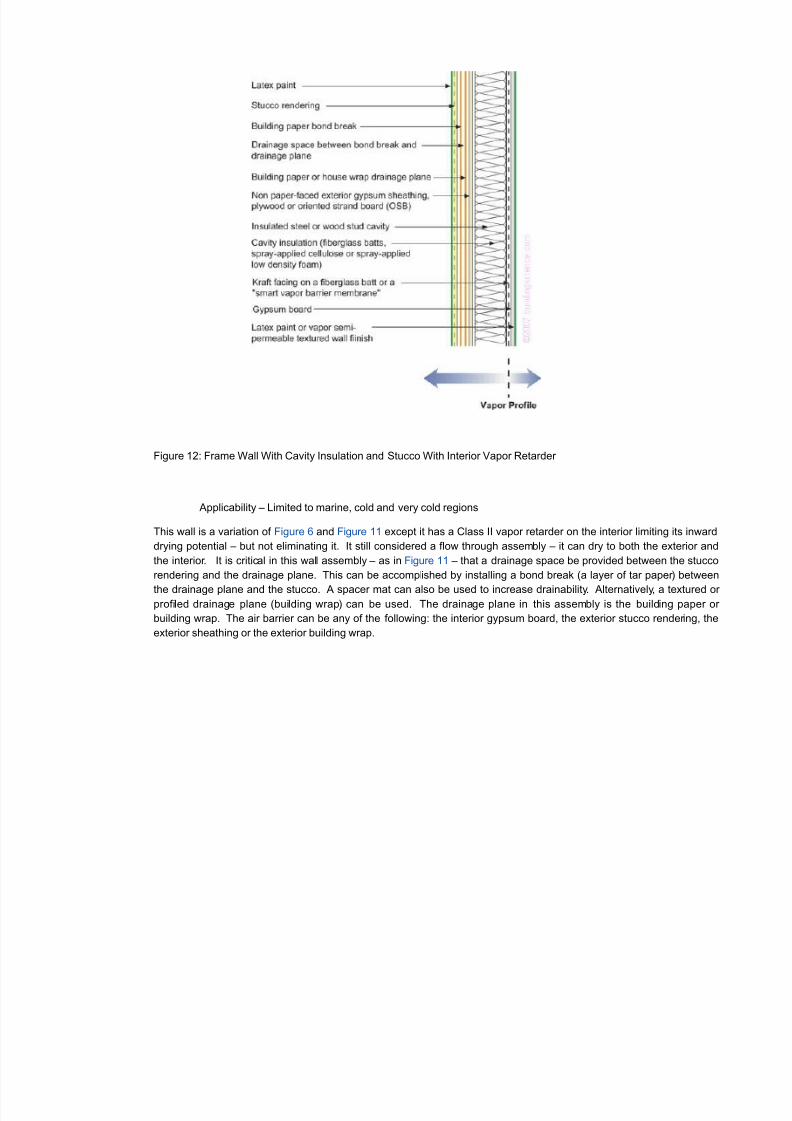
Figure 12: Frame Wall With Cavity Insulation and Stucco With Interior Vapor Retarder
Applicability – Limited to marine, cold and very cold regions
This wall is a variation of Figure 6 and Figure 11 except it has a Class II vapor retarder on the interior limiting its inward
drying potential – but not eliminating it. It still considered a flow through assembly – it can dry to both the exterior and
the interior. It is critical in this wall assembly – as in Figure 11 – that a drainage space be provided between the stucco
rendering and the drainage plane. This can be accomplished by installing a bond break (a layer of tar paper) between
the drainage plane and the stucco. A spacer mat can also be used to increase drainability. Alternatively, a textured or profiled drainage plane (building wrap) can be used. The drainage plane in this assembly is the building paper or
building wrap. The air barrier can be any of the following: the interior gypsum board, the exterior stucco rendering, the
exterior sheathing or the exterior building wrap.
8/3/2019 Vapour Barriers
http://slidepdf.com/reader/full/vapour-barriers 15/23
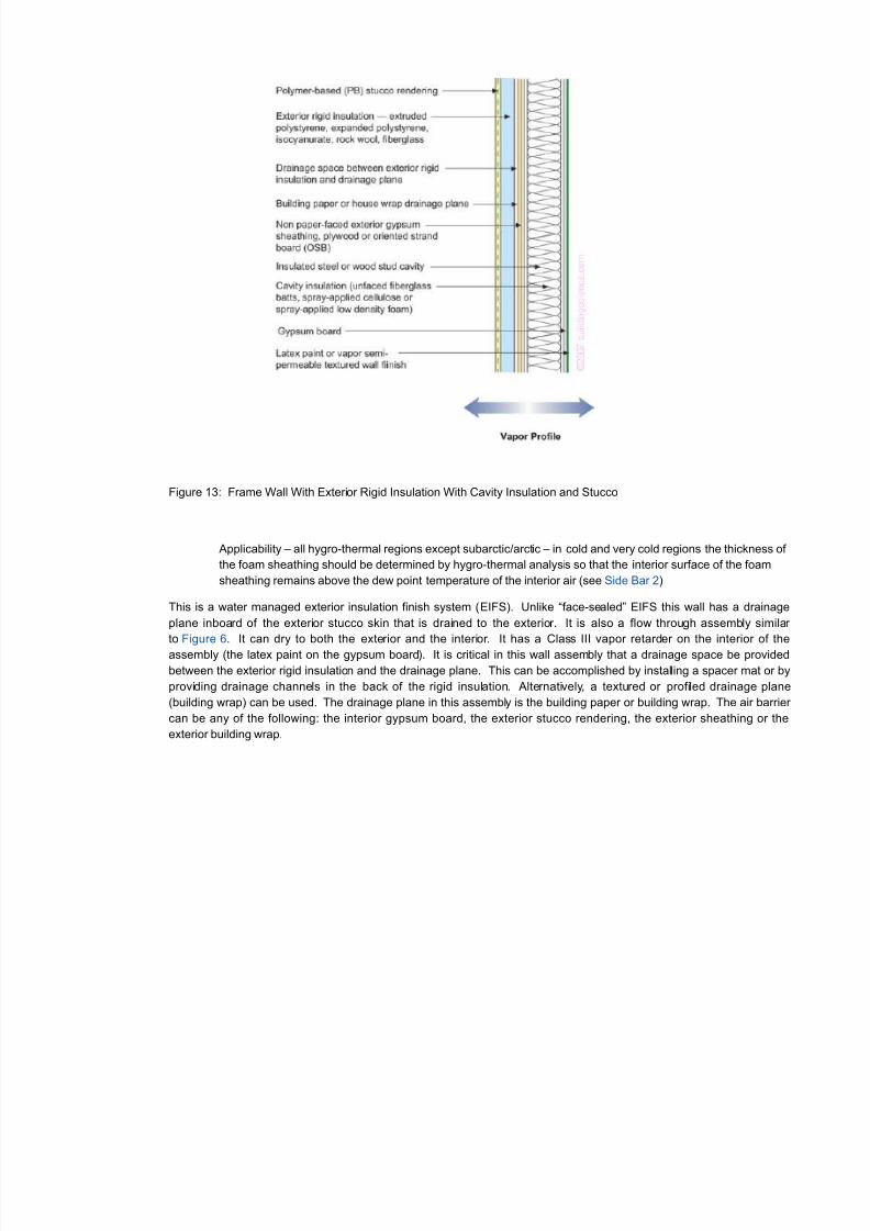
Figure 13: Frame Wall With Exterior Rigid Insulation With Cavity Insulation and Stucco
Applicability – all hygro-thermal regions except subarctic/arctic – in cold and very cold regions the thickness of
the foam sheathing should be determined by hygro-thermal analysis so that the interior surface of the foam
sheathing remains above the dew point temperature of the interior air (see Side Bar 2)
This is a water managed exterior insulation finish system (EIFS). Unlike “face-sealed” EIFS this wall has a drainage
plane inboard of the exterior stucco skin that is drained to the exterior. It is also a flow through assembly similar
to Figure 6. It can dry to both the exterior and the interior. It has a Class III vapor retarder on the interior of the
assembly (the latex paint on the gypsum board). It is critical in this wall assembly that a drainage space be provided
between the exterior rigid insulation and the drainage plane. This can be accomplished by installing a spacer mat or by
providing drainage channels in the back of the rigid insulation. Alternatively, a textured or profiled drainage plane
(building wrap) can be used. The drainage plane in this assembly is the building paper or building wrap. The air barrier
can be any of the following: the interior gypsum board, the exterior stucco rendering, the exterior sheathing or the
exterior building wrap.
8/3/2019 Vapour Barriers
http://slidepdf.com/reader/full/vapour-barriers 16/23
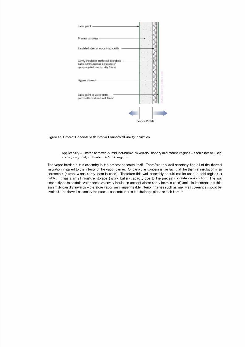
Figure 14: Precast Concrete With Interior Frame Wall Cavity Insulation
Applicability – Limited to mixed-humid, hot-humid, mixed-dry, hot-dry and marine regions – should not be used
in cold, very cold, and subarctic/arctic regions
The vapor barrier in this assembly is the precast concrete itself. Therefore this wall assembly has all of the thermal
insulation installed to the interior of the vapor barrier. Of particular concern is the fact that the thermal insulation is air
permeable (except where spray foam is used). Therefore this wall assembly should not be used in cold regions or
colder. It has a small moisture storage (hygric buffer) capacity due to the precast concrete construction. The wall
assembly does contain water sensitive cavity insulation (except where spray foam is used) and it is important that thisassembly can dry inwards – therefore vapor semi impermeable interior finishes such as vinyl wall coverings should be
avoided. In this wall assembly the precast concrete is also the drainage plane and air barrier.
8/3/2019 Vapour Barriers
http://slidepdf.com/reader/full/vapour-barriers 17/23
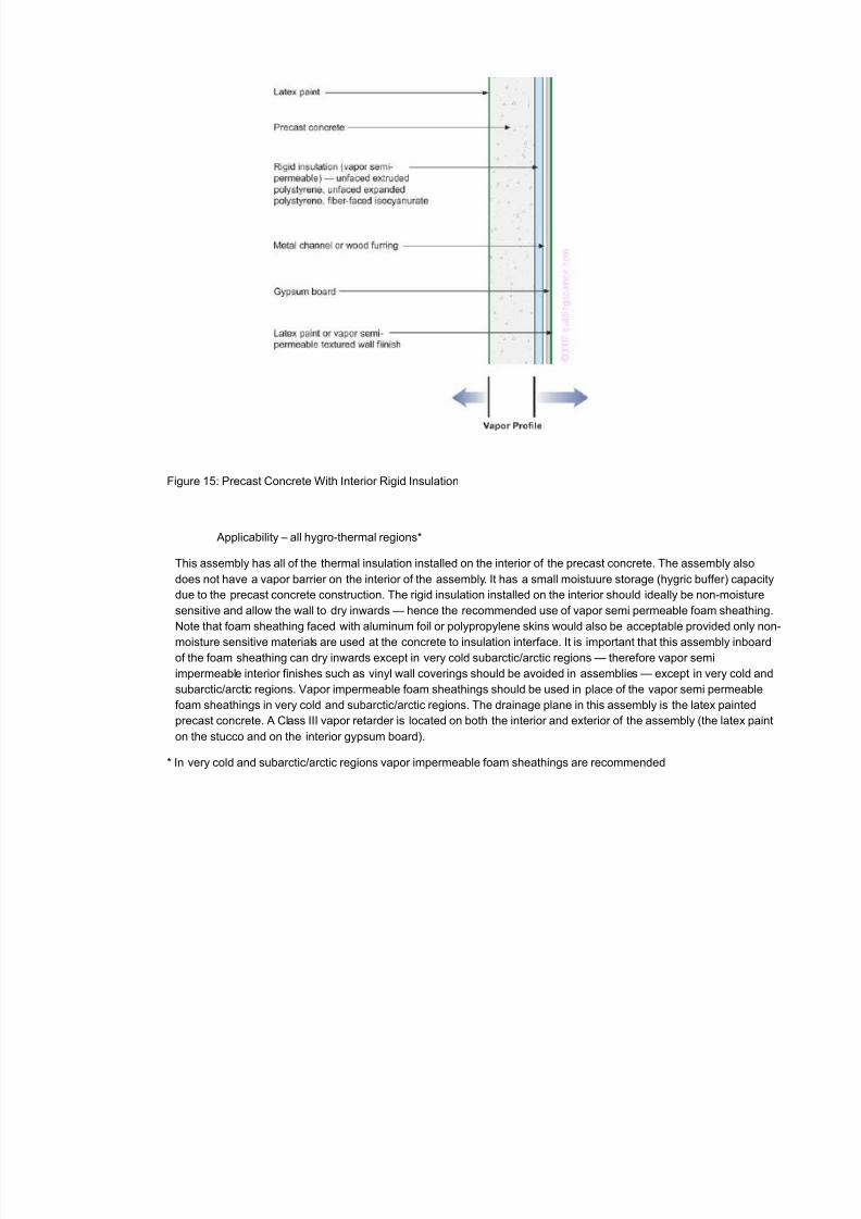
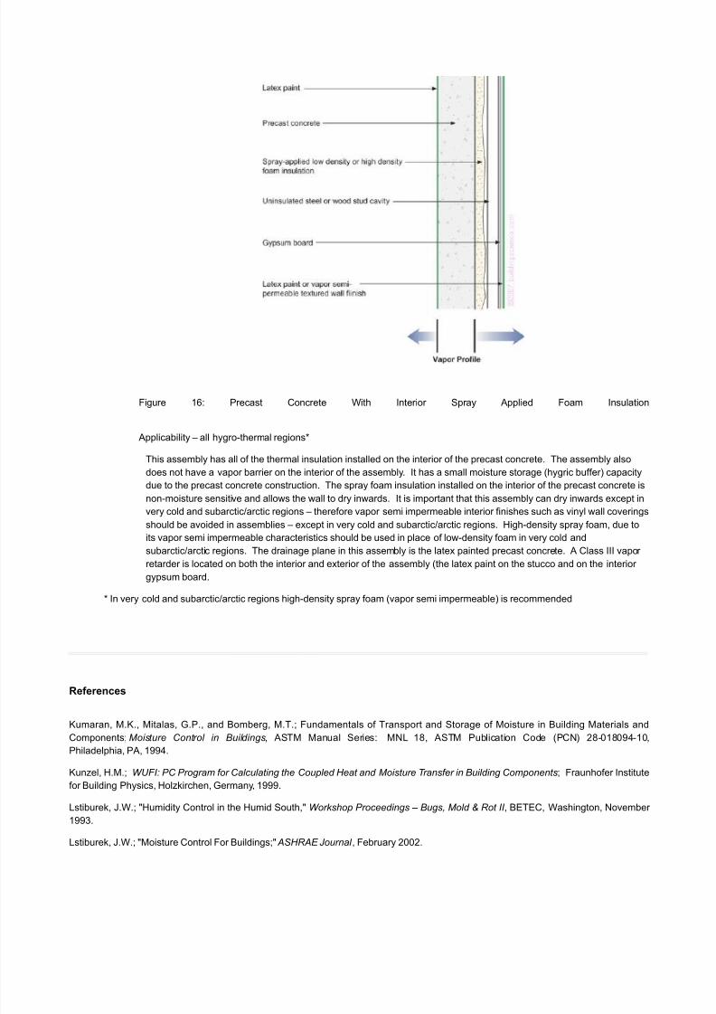
Figure 15: Precast Concrete With Interior Rigid Insulation
Applicability – all hygro-thermal regions*
This assembly has all of the thermal insulation installed on the interior of the precast concrete. The assembly also
does not have a vapor barrier on the interior of the assembly. It has a small moistuure storage (hygric buffer) capacity
due to the precast concrete construction. The rigid insulation installed on the interior should ideally be non-moisture
sensitive and allow the wall to dry inwards — hence the recommended use of vapor semi permeable foam sheathing.
Note that foam sheathing faced with aluminum foil or polypropylene skins would also be acceptable provided only non-
moisture sensitive materials are used at the concrete to insulation interface. It is important that this assembly inboardof the foam sheathing can dry inwards except in very cold subarctic/arctic regions — therefore vapor semi
impermeable interior finishes such as vinyl wall coverings should be avoided in assemblies — except in very cold and
subarctic/arctic regions. Vapor impermeable foam sheathings should be used in place of the vapor semi permeable
foam sheathings in very cold and subarctic/arctic regions. The drainage plane in this assembly is the latex painted
precast concrete. A Class III vapor retarder is located on both the interior and exterior of the assembly (the latex paint
on the stucco and on the interior gypsum board).
* In very cold and subarctic/arctic regions vapor impermeable foam sheathings are recommended
8/3/2019 Vapour Barriers
http://slidepdf.com/reader/full/vapour-barriers 18/23
8/3/2019 Vapour Barriers
http://slidepdf.com/reader/full/vapour-barriers 19/23
Lstiburek, J.W.; "Investigating Diagnosing Moisture Problems," ASHRAE Journal , December 2002.
Quirouette, R.L.; The Difference Between a Vapor Barrier and an Air Barrier ; Building Practice Note 54, Division of Building Research,
National Research Council of Canada, ISSN 0701-5216, Ottawa, Ontario, Canada, July 1985.
Rose, W.; Moisture Control in the Modern Building Envelope: The History of the Vapor Barrier in the US – 1923 to 1952 , APT, Volume
XXVIII, Number 4, 1997
Sidebar 1
Hygro-Thermal Regions
Subarctic and Arctic
A subarctic and arctic climate is defined as a region with approximately 12,600 heating degree days (65 degrees F basis) [7,000 heating
degree days (18 degrees C basis)] or greater.
Very Cold
A very cold climate is defined as a region with approximately 9,000 heating degree days or greater (65 degrees F basis) [5,000 heating
degree days (18 degrees C basis)] or greater and less than 12,600 heating degree days (65 degrees F basis) [7,000 heating degree
days (18 degrees C basis)].
Cold
A cold climate is defined as a region with approximately 5,400 heating degree days (65 degrees F basis) [3,000 heating degree days (18
degrees C basis)] or greater and less than approximately 9,000 heating degree days (65 degrees F basis) [5,000 heating degree days
(18 degrees C basis)].
Mixed-Humid
A mixed-humid and warm-humid climate is defined as a region that receives more than 20 inches (50 cm) of annual precipitation with
approximately 4,500 cooling degree days (50 degrees F basis) [2,500 cooling degree days (10 degrees C basis)] or greater and less
than approximately 6,300 cooling degree days (50 degrees F basis) [3,500 cooling degree days (10 degrees C basis)] and less than
approximately 5,400 heating degree days (65 degrees F basis) [3,000 heating degree days (18 degrees C basis)] and where the
average monthly outdoor temperature drops below 45 degrees F (7 degrees C) during the winter months.
Marine
A marine climate meets is defined as a region where all of the following occur:
• a mean temperature of the coldest month between 27 degrees F (-3 degrees C) and 65 degrees F (18 degrees C);
• a mean temperature of the warmest month below 72 degrees F (18 degrees C);
• at least four months with mean temperatures over 50 degrees F (10 degrees C); and
8/3/2019 Vapour Barriers
http://slidepdf.com/reader/full/vapour-barriers 20/23
• a dry season in the summer, the month with the heaviest precipitation in the cold season has at least three times as much
precipitation as the month with the least precipitation.
Hot-Humid
A hot-humid climate is defined as a region that receives more than 20 inches (50 cm) of annual precipitation with approximately 6,300
cooling degree days (50 degrees F basis) [3,500 cooling degree days (10 degrees C basis)] or greater and where the monthly averageoutdoor temperature remains above 45 degrees F (7 degrees C) throughout the year.
This definition characterizes a region that is similar to the ASHRAE definition of hot-humid climates where one or both of the following
occur:
• a 67 degree F (19.5 degrees C) or higher wet bulb temperature for 3,000 or more hours during the warmest six consecutive
months of the year; or
• a 73 degree F (23 degrees C) or higher wet bulb temperature for 1,500 or more hours during the warmest six consecutive
months of the year.
Hot-Dry, Warm-Dry and Mixed-Dry
A hot-dry climate is defined as region that receives less than 20 inches (50 cm) of annual precipitation with approximately 6,300 cooling
degree days (50 degrees F basis) [3,500 cooling degree days (10 degrees C basis)] or greater and where the monthly average outdoor
temperature remains above 45 degrees F (7 degrees C) throughout the year.
A warm-dry and mixed-dry climate is defined as a region that receives less than 20 inches (50 cm) of annual precipitation with
approximately 4,500 cooling degree days (50 degrees F basis) [2,500 cooling degree day (10 degrees C basis)] or greater and less than
approximately 6,300 cooling degree days (50 degrees F basis) [3,500 cooling degree days (10 degrees C basis)] and less than
approximately 5,400 heating degree days (65 degrees F basis) [3,000 heating degree days (18 degrees C basis)] and where the
average monthly outdoor temperature drops below 45 degrees F (7 degrees C) during the winter months.
Side Bar 2
Recommendations for Vapor Retarders
The recommendations are based on a combination of field experience and laboratory testing. The requirements were also evaluated
using dynamic hygrothermal modeling. The modeling program used was WUFI (Kunzel, 1999). Under the modeling evaluation, the
moisture content of building materials that comprise the building assemblies evaluated all remained below the equilibrium moisture
content of the materials as specified in ASHRAE 160 P. Interior air conditions and exterior air conditions as specified by ASHRAE 160 P
were used. Enclosures are ventilated meeting ASHRAE Standard 62.1 or 62.2.
The climate zones referenced are the U.S. Department of Energy climate zones as proposed for adoption in the 2006 International
Residential Code (IRC) and International Energy Conservation Code (IECC). Their development is the subject of two ASHRAE papers
(Briggs, Lucas & Taylor, 2003). An accompanying map defines the climate zones.
Note that vapor retarders are defined and classed using ASTM E-96 Test Method A (the desiccant method or dry cup method) or Test
Method B (the wet cup method).
1. Zone 1, Zone 2, Zone 3 and Zone 4 (except Zone 4 Marine) do not require any class of vapor retarder on the interior surface of
insulation in insulated wall and floor assemblies.
2. Zone 4 (marine) requires a Class II (or lower) vapor retarder on the interior surface of insulation in insulated wall and floor
8/3/2019 Vapour Barriers
http://slidepdf.com/reader/full/vapour-barriers 21/23
assemblies where the permeance of the exterior sheathing/cladding assembly is less than or equal to 1.0 perm and greater than 0.1
perm as tested by Test Method B (the “wet cup” method) of ASTM E-96).
3. Zone 4 (marine) requires a Class III (or lower) vapor retarder on the interior surface of insulation in insulated wall and floor
assemblies where the permeance of the exterior sheathing is 0.1 perm or less as tested by Test Method B (the “wet cup” method) of
ASTM E-96) and the interior surface of the exterior sheathing shall be maintained above the dew point temperature of the interior air.
Under this design approach assume steady state heat transfer, interior air at a temperature of 70 degrees F (21 degrees C), at a relative
humidity specified inTable 1 and exterior air at a temperature that is equal to the average outdoor temperature for the location during the
coldest three months of the year (e.g. December, January and February).
4. Zone 5 requires a Class III (or lower) vapor retarder on the interior surface of insulation in insulated wall and floor assemblies where
the permeance of the exterior sheathing is greater than 1.0 perm as tested by Test Method B (the “wet cup” method) of ASTM E-96).
5. Zone 6 and Zone 7 require a Class II (or lower) vapor retarder on the interior surface of insulation in insulated wall and floor
assemblies where the permeance of the exterior sheathing is greater than 1.0 perm as tested by Test Method B (the “wet cup” method)
of ASTM E-96).
6. Zone 5, Zone 6 and Zone 7 require a Class II (or lower) vapor retarder on the interior surface of insulation in insulated wall and floor
assemblies where the permeance of the exterior sheathing/cladding assembly is less than or equal to 1.0 perm and greater than 0.1
perm as tested by Test Method B (the “wet cup” method) of ASTM E-96).
7. Zone 5, Zone 6 and Zone 7 require a Class II (or lower) vapor retarder on the interior surface of insulation in insulated wall and floor
assemblies where the permeance of the exterior sheathing is 0.1 perm or less as tested by Test Method B (the “wet cup” method) of
ASTM E-96) and the interior surface of the exterior sheathing shall be maintained above the dew point temperature of the interior air.
Under this design approach assume steady state heat transfer, interior air at a temperature of 70 degrees F (21 degrees C), at a relative
humidity specified inTable 1 and exterior air at a temperature that is equal to the average outdoor temperature for the location during the
coldest three months of the year (e.g. December, January and February).
TABLE 1: DESIGN CONDITIONS FOR STEADY STATE DESIGN PROCEEDURE – WALL AND FLOOR ASSEMBLIES
(not the actual service conditions for typical residential occupancy – but the design conditions for the simple steady state design
procedure being used)
Zone 4 (marine) 40 percent RH @ 70 degrees F (Dew Point 45 degrees F)
Zone 5 30 percent RH @ 70 degrees F (Dew Point 37 degrees F)
Zone 6 25 percent RH @ 70 degrees F (Dew Point 32 degrees F)
Zone 7 20 percent RH @ 70 degrees F (Dew Point 28 degrees F)
TABLE 2: DESIGN CONDITIONS FOR STEADY STATE DESIGN PROCEEDURE – ROOF AND ATTIC ASSEMBLIES
(not the actual service conditions for typical residential occupancy – but the design conditions for the simple steady state design
procedure being used)
Zone 5 35 percent RH @ 70 degrees F (Dew Point 39 degrees F)
Zone 6 30 percent RH @ 70 degrees F (Dew Point 37 degrees F)
Zone 7 25 percent RH @ 70 degrees F (Dew Point 32 degrees F)
8. Zone 5 requires a Class III (or lower) vapor retarder on the interior surface of insulation in ventilated insulated roof or attic
assemblies.
9. Zone 5, Zone 6 and Zone 7 require a Class II (or lower) vapor retarder on the interior surface of insulation in unvented insulated roof
or attic assemblies and the condensing surface shall be maintained above the dew point temperature of the interior air. The condensing
surface is defined as either the interior surface of the structural roof deck or the interior surface of an air-impermeable insulation applied
in direct contact to the underside/interior of the structural roof deck. “Air-impermeable” is quantitatively defined by ASTM E 283. Under
8/3/2019 Vapour Barriers
http://slidepdf.com/reader/full/vapour-barriers 22/23
this design approach assume steady state heat transfer, interior air at a temperature of 70 degrees F (21 degrees C), at a relative
humidity specified in Table 2 and exterior air at a temperature that is equal to the average outdoor temperature for the location during the
coldest three months of the year (e.g. December, January and February).
10. Zone 6 and Zone 7 require a Class II (or lower) vapor retarder on the interior surface of insulation in ventilated insulated roof or
attic assemblies.
11. Concrete slab floors in ground contact are required to have a Class I vapor retarder below the slab in direct contact with the slab or
r igid insulation having a thermal resistance of at least R-5 below the slab in direct contact with the slab.
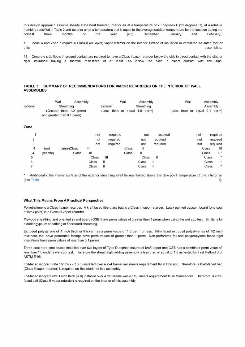
TABLE 3: SUMMARY OF RECOMMENDATIONS FOR VAPOR RETARDERS ON THE INTERIOR OF WALLASSEMBLIES
Wall Assembly Wall Assembly Wall Assembly
Exterior Sheathing Exterior Sheathing Assembly
(Greater than 1.0 perm) (Less than or equal 1.0 perm) (Less than or equal 0.1 perm)
and greater than 0.1 perm)
Zone
1 not required not required not required
2 not required not required not required
3 not required not required not required
4 (not marine)Class III Class III Class III
4 (marine) Class III Class II Class III*
5 Class III Class II Class II*
6 Class II Class II Class II*
7 Class II Class II Class II*
* Additionally, the interior surface of the exterior sheathing shall be maintained above the dew point temperature of the interior air
(see Table 1).
What This Means From A Practical Perspective
Polyethylene is a Class I vapor retarder. A kraft faced fiberglass batt is a Class II vapor retarder. Latex painted gypsum board (one coat
of latex paint) is a Class III vapor retarder.
Plywood sheathing and oriented strand board (OSB) have perm values of greater than 1 perm when using the wet cup test. Similarly for
exterior gypsum sheathing or fiberboard sheathing.
Extruded polystyrene of 1 inch thick or thicker has a perm value of 1.0 perm or less. Film faced extruded polystyrenes of 1/2 inch
thickness that have perforated facings have perm values of greater than 1 perm. Non-perforated foil and polypropylene faced rigid
insulations have perm values of less than 0.1 perms.
Three-coat hard-coat stucco installed over two layers of Type D asphalt saturated kraft paper and OSB has a combined perm value of
less than 1.0 under a wet cup test. Therefore the sheathing/cladding assembly is less than or equal to 1.0 as tested by Test Method B of
ASTM E-96.
Foil-faced isocyanurate 1/2 thick (R 3.5) installed over a 2x4 frame wall meets requirement #9 in Chicago. Therefore, a kraft-faced batt
(Class II vapor retarder) is required on the interior of this assembly.
Foil-faced isocyanurate 1 inch thick (R 6) installed over a 2x6 frame wall (R 19) meets requirement #9 in Minneapolis. Therefore, a kraft-
faced batt (Class II vapor retarder) is required on the interior of this assembly.
8/3/2019 Vapour Barriers
http://slidepdf.com/reader/full/vapour-barriers 23/23
In Chicago where plywood or OSB exterior sheathing is used, an unfaced fiberglass batt can be installed within the wall cavity and
gypsum board painted with latex paint (Class III vapor retarder) is required on the interior of this assembly. If this assembly is moved to
Minneapolis, a Class II vapor retarder is required on the interior (a kraft paper faced fiberglass batt).
References
Briggs, R.S., Lucas, R.G., and Taylor, T.; Climate Classification for Building Energy Codes and Standards: Part 1 – Development
Process, Technical & Symposium Papers, ASHRAE Winter Meeting, Chicago, IL, January, 2003.
Briggs, R.S., Lucas, R.G., and Taylor, T.; Climate Classification for Building Energy Codes and Standards: Part 2 – Zone Definitions,
Maps and Comparisons, Technical & Symposium Papers, ASHRAE Winter Meeting, Chicago, IL, January, 2003.
Kunzel, H.M.; WUFI: PC Program for Calculating the Coupled Heat and Moisture Transfer in Building Components; Fraunhofer Institute
for Building Physics, Holzkirchen, Germany, 1999.