Embed Size (px)
Citation preview

Performance Floors for
Warehouses and Distribution Centres
Kevin Dare, Managing Director,
Face Consultants Ltd.
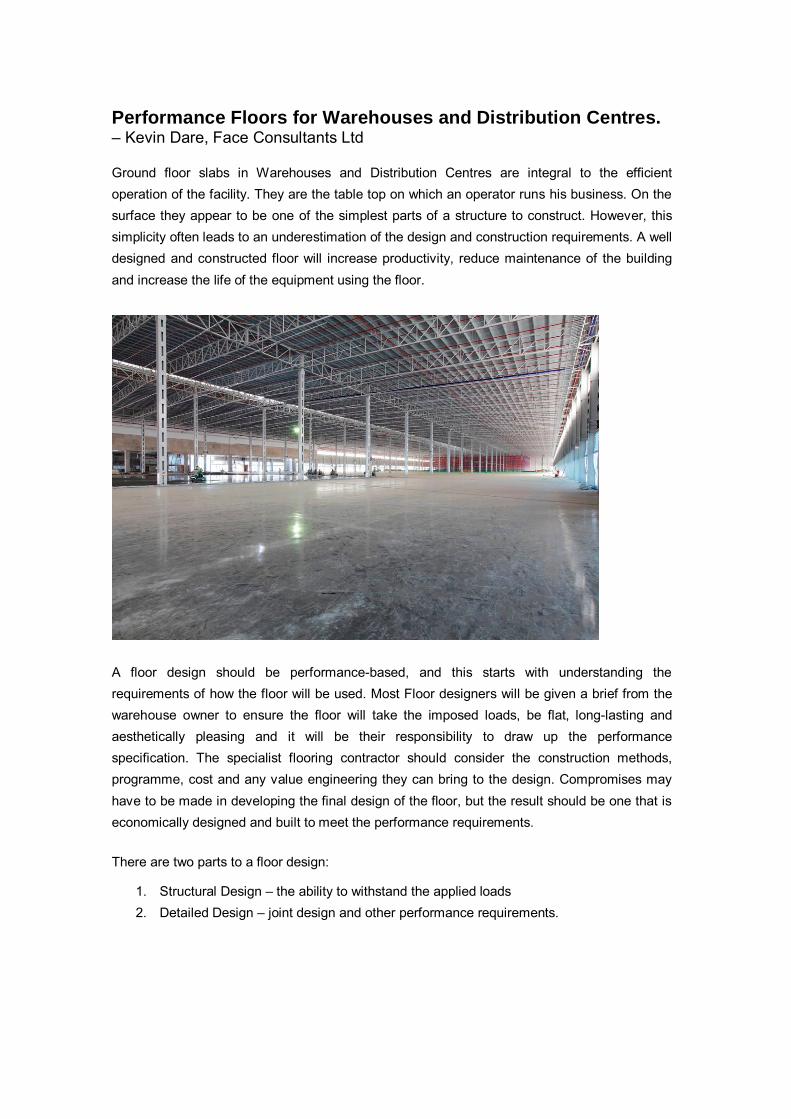
Performance Floors for Warehouses and Distribution Centres. – Kevin Dare, Face Consultants Ltd Ground floor slabs in Warehouses and Distribution Centres are integral to the efficient operation of the facility. They are the table top on which an operator runs his business. On the surface they appear to be one of the simplest parts of a structure to construct. However, this simplicity often leads to an underestimation of the design and construction requirements. A well designed and constructed floor will increase productivity, reduce maintenance of the building and increase the life of the equipment using the floor.
A floor design should be performance-based, and this starts with understanding the requirements of how the floor will be used. Most Floor designers will be given a brief from the warehouse owner to ensure the floor will take the imposed loads, be flat, long-lasting and aesthetically pleasing and it will be their responsibility to draw up the performance specification. The specialist flooring contractor should consider the construction methods, programme, cost and any value engineering they can bring to the design. Compromises may have to be made in developing the final design of the floor, but the result should be one that is economically designed and built to meet the performance requirements.
There are two parts to a floor design:
1. Structural Design – the ability to withstand the applied loads 2. Detailed Design – joint design and other performance requirements.
Structural Design The structural design of a floor will follow engineering principles and calculations and requires knowledge of the following in order to determine the slab thickness and reinforcement.
1. Ground conditions 1. Strength of the concrete 2. Thickness of the concrete 3. Method of reinforcement 4. Load transfer capability of the joints 5. Loading specification and loading pattern
Guidance on the design of a floor is detailed in the UK Concrete Society’s Technical Report 34 (TR34)
Detail design Detail design covers key performance requirements, including:
1. Joint layout and joint design 2. Construction methods 3. Method of reinforcement. 4. Surface regularity (flatness and levelness) 5. Abrasion resistance
Advice from all the stakeholders of the floor should be sought before the design is finalised,
Structural Design
Sub-grade
Suitable ground conditions are essential for ground supported slabs, and it is therefore important that a ground investigation is carried out and interpreted by a competent geotechnical engineer. The geotechnical engineer must advise on the suitability of the ground along with any recommendations for ground improvements.
Sub-base
The primary purpose of the sub-base is to provide a level base for the floor slab. It should be capable of carrying construction traffic without rutting. The sub-base should be a minimum 200-250mm thick well graded material. The level tolerance of the sub-base is of great importance. A high sub-base generally means a thinner concrete floor. + Zero – 25mm is recommended.
Slip membranes
Slip membranes are used to reduce friction between the slab and the sub-base so as to reduce the restraint to drying shrinkage thus reducing the risk of unplanned cracking. A 300μm plastic sheeting is recommended. Concrete There are comprehensive Standards for the specification and testing of concrete. High strength concrete is not needed and should be avoided because it tends to have higher cement content and is more likely to shrink than lower strength concrete. It can also be difficult to finish. Concrete shrinks as it dries out over the first 12-18 months of its life. Fresh concrete has more water than is needed for the chemical process of hardening and some of this excess water leaves the concrete causing it to shrink. Therefore, the amount of cement and water in the concrete should not be excessive. Consistency of the material properties and delivery to site is the key to a well finished floor slab.
Reinforcement
Although reinforcement will give some enhancement to the structural load capacity of the floor slab, the primary function is to restrain the opening of sawn induced joints and maintain good load transfer properties. The traditional method of reinforcement in jointed ground supported slabs is with steel mesh. The position of the mesh is usually specified 50mm from the bottom of the slab. Alternatively, floors can be reinforced with steel fibres. Caution must be taken with nominally reinforced steel fibre slabs (less than 35Kg per cubic metre) with saw cut joints. The joints can become wider than predicted and load transfer between sections of floor can be lost. This can result in floor movement at the joints an breakdown of the joint. Steel fibre Jointless slabs, with no saw cuts joints can offer the warehouse user a floor with reduced maintenance but this method comes with some words of caution. The quantity of steel fibre should always be equal to or greater than 35kg/m3.
Detail Design Joints Joints are the most critical element in a floor. Most maintenance requirements are related to the breakdown of joints in some form. Joints create unavoidable discontinuities in a floor which

can be damaged by mechanical handling equipment when trafficked. Joints are provided for two purposes:
• To form the boundaries of each day’s concrete pour (Construction Joints)
• To reduce the risk of cracking as the floor shrinks (Contraction Joints and isolation details)
Figure 1: Typical armoured construction joint detail Construction joints must incorporate dowels to provide a load transfer mechanism between the sections of floor.
Contraction Joints
Contraction joints are most commonly created by saw cutting. Sections of cast floor are usually cut into panels of 6m x 6m. The intention is that a crack will then form beneath the saw cut relieving drying shrinkage stresses. A typical detail is shown in Figure 2. The reinforcement must be continuous across the sawn joint to restrain the opening of the engineered crack and maintain adequate load transfer.
Figure 2: Typical contraction joint detail

Isolation details
Floors must be isolated from fixed elements of the building to allow the floor to contract without cracking. This is achieved by surrounding columns with compressible materials. These are known as the isolation details.
Joint Layouts
Ground supported slabs can be jointed or jointless.
1. Jointed floors have construction joints at the edges of each day’s concrete pour, and they typically have sawn joints at 6m intervals.
2. The term jointless is something of a misnomer as all slabs have construction joints at the edges of areas of floor that are poured in any one day. On a jointless floor, these are the only joints.
Joints are provided to permit breaks in construction and to allow for shrinkage as the concrete dries out over a period of up to 2 years.
Jointless Floors
Some floors are built without sawn joints. These are usually fibre reinforced. The principle is that the steel fibres limit the crack widths of shrinkage cracking. Care must be taken to ensure that all possible steps are taken to minimise the restraint to shrinkage, including mix design, correct curing, and limiting pour sizes.
Flatness and Levelness Requirements (Surface Regularity) There are essentially two methods for defining floor flatness requirements. Floors are divided into Free Movement Areas (FM) and Defined Movement Areas (DM). The FM criteria is where trucks operate at low level when moving, such as marshalling areas, block stacking areas, and aisles greater than 2.8m wide. See figure 3.

Figure 3: Free Movement Area Figure 4: VNA
DM areas refer to systems where the trucks are constrained to defined, fixed paths such as Very Narrow Aisle (VNA). See Figure 4

Methods of defining floor tolerances can be found in Table 1 below:
Standard Free Movement Defined Movement
Concrete Society TR34 Table 3.1 Table 3.2
CEN - EN 15620, Table 5
ASTM / ACI ASTM E 1155M ACI Fmin
Table 1: Methods for defining floor tolerances
Free Movement For Free Movement Floors there are two standards to consider:
1. TR34 Edition 4 2014 Table 3.1 2. ASTM E 1155 M – F numbers
The TR34 specification is the most comprehensive method of specifying the surface regularity of free movement floors. It controls the short wavelength, Property F shown in Figure 5; the long wavelength, Property E shown in Figure 16; and datum. The specification clearly defines how the floor should be sampled and analysed.
Figure 5: Measurement of Property F Figure 6: Property E is the difference in elevation of points 3m apart on an orthogonal grid

Table 2 shows the Free Movement classifications from TR34.
Floor classification Typical floor use
Property F (mm)
Property E (mm)
95% 100%
95% 100%
FM 1 Where very high standards of flatness and levelness are required. Reach trucks operating at above 13 metres without side-shift
1.8 4.5
FM 2 Reach Trucks operating at 8 – 13 m without side-shift 2.0 6.5
FM 3 Retail floors to take directly applied flooring. Reach trucks operating at up to 8m without side shift. Rich trucks operating at up to 13 metres with side shift.
2.2 8.0
FM4 Retail Floors to take applied screeds. Workshops and manufacturing facilities where MHE lift heights are restricted to 4 metres
2.4 10.0
NOTE 1: The above values are permissible 95 percentile values for Properties F and E NOTE 2: For all classifications, all points surveyed should be within 15mm from datum.
Table 2: Floor classification for free movement (Modified Table 4.2 from TR34)
The ASTM is a comprehensive method of measuring the overall performance of the floor based on statistical analysis known as F numbers. The standard is based on two numbers: FF for flatness (short wavelength) and FL for levelness (long wavelength). However, there is no control to datum and the sample rate is comparatively small. Equivalent ASTM F numbers for TR34 Classifications are given in Table 3.
UK Concrete Society TR34 ASTM F number system
Flatness Levelness Datum Flatness Levelness Datum
Property II Property IV FF FL
FM1 FM1 +/- 15mm 50 40 N.A.
FM2 FM2 +/- 15mm 45 35 N.A.
FM3 FM3 +/- 15mm 40 30 N.A.
FM4 FM4 +/- 15mm 30 20 N.A.
NOTES: A direct comparison is not possible as the above specifications have different methods of data collection and data analysis. The above comparisons are not direct numerical comparisons but are based on the results of over 5 million square metres of floor survey results.
Table 3: Comparison of TR34 and ASTM Free Movement Specifications
Defined Movement Floors For Defined Movement Floors there are three standards to consider:
1. TR34 Edition 4 2013 Table 3.2 2. ACI Fmin 3. EN 15620

These three specifications measure the floor’s profile in the same format using a profileograph rig which replicates the footprint of a forklift, as can be seen in Figure 7.
Figure 7: Face Digital Profileograph within a narrow aisle
The equipment measures the elevation across the load wheels (transverse) and the elevation between the front and rear axles of the truck (longitudinal) as can be seen in Figures 8 and 9. In addition to the elevation controls, the rate of change in elevation for both transverse and longitudinal directions is measured for every 300mm of travel down the defined path.
Fig 8: Elevation of the load wheels (dZ - transverse) and rate in change of elevation over 300mm travel distance (d2Z).
Fig 9: Elevation of the front to rear axle (dX - longitudinal) and rate in change of elevation over 300mm travel distance (d2X).
Although the three standards described above measure the floor properties in the same method, the property limits vary. TR34 and CEN 15620 have the same limits. The TR34 property limits are shown in Table 4.

Floor classification
MHE lift height
Property Z slope Property dZ Property
d2Z Property dX Property d2X The cross-aisle slope between the centres of the truck wheels in mm/m
Z x Z slope dZ x 0.75 2 x Z slope x 1.1 Fixed Value
DM 1 Over 13 m 1.3 Z x 1.3 Z x 1.0 2.9 1.5
DM 2 8 to 13 m 2.0 Z x 2.0 Z x 1.5 4.4 2.0
DM 3 Up to 8 m 2.5 Z x 2.5 Z x 1.9 5.5 2.5
Where: Z is the Transverse dimension between the centres of the truck front wheels in mm
Table 4: Floor classification for defined movement (TR34 Table C1)
TR34 Table 3.2 CEN 15620 ACI Fmin numbers
DM1 DM1 100
DM2 DM2 75
DM3 DM3 50
Table 5: Comparison of TR3, CEN and ACI Fmin Defined Movement Specifications.
Recommendations on Surface Regularity TR34 Edition 3 2003 provides the most comprehensive guidance on the subject. For most installations, TR34 Classification FM2 is recommended when specifying a new floor as this represents a good quality floor that can be achieved without excessive cost. For VNA applications a DM Specification should be used and the category defined by the racking height.
Abrasion Resistance / Durability For most warehouse applications, a self-finished, power-trowelled slab will provide a durable working surface, provided that concrete selection is correct and good finishing techniques are applied. Surface durability is primarily a function of the densification of the surface by power-trowelling and most importantly by proper curing.
Construction Methods The floor construction method is critical in determining the overall detailed design, construction programme and cost. The construction method will determine:
1. Daily output - programme 2. Joint layout Surface regularity 3. The concrete mix design 4. How the floor is reinforced

There are 4 basic methods of construction:
1. Long Strip 2. Large Area Pour – Laser Screed – Jointed 3. Large Area Pour – Laser Screed – Jointless
Long Strip
The long strip method of construction is a traditional method of laying industrial floor slabs. The floor is laid in a series of long strips, typically 4-5m wide.
Figure 10: Long strip construction
The long strip method is still commonly used when the floor must have a very high level of surface regularity such as VNA. An experienced flooring contractor should be able to achieve a high degree of flatness using the long strip method without corrective grinding.
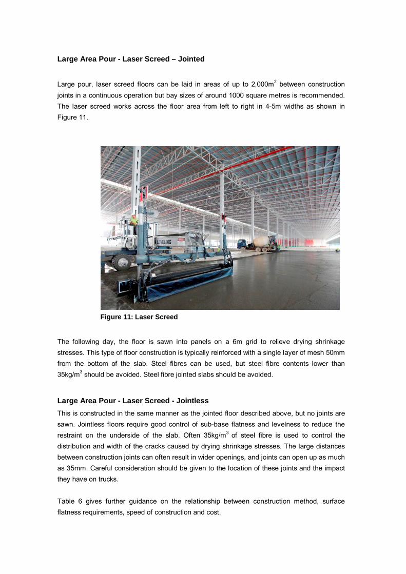
Large Area Pour - Laser Screed – Jointed Large pour, laser screed floors can be laid in areas of up to 2,000m2 between construction joints in a continuous operation but bay sizes of around 1000 square metres is recommended. The laser screed works across the floor area from left to right in 4-5m widths as shown in Figure 11.
Figure 11: Laser Screed
The following day, the floor is sawn into panels on a 6m grid to relieve drying shrinkage stresses. This type of floor construction is typically reinforced with a single layer of mesh 50mm from the bottom of the slab. Steel fibres can be used, but steel fibre contents lower than 35kg/m3 should be avoided. Steel fibre jointed slabs should be avoided.
Large Area Pour - Laser Screed - Jointless This is constructed in the same manner as the jointed floor described above, but no joints are sawn. Jointless floors require good control of sub-base flatness and levelness to reduce the restraint on the underside of the slab. Often 35kg/m3 of steel fibre is used to control the distribution and width of the cracks caused by drying shrinkage stresses. The large distances between construction joints can often result in wider openings, and joints can open up as much as 35mm. Careful consideration should be given to the location of these joints and the impact they have on trucks. Table 6 gives further guidance on the relationship between construction method, surface flatness requirements, speed of construction and cost.

Construction Method Comparison
Construction Method Best Surface regularity* Speed of
construction Typical Cost comparison***
(multiple)
DM FM Typical m2 per day Materials Labour and plant
Long Strip 1 1 400 1 3 Large Pour - Laser Screed -
Jointed 2** 1 / 2 1000 - 1500 1**** 1
Large Pour - Laser Screed - Jointless 2** 1 / 2 1000 - 1500 1.3 1
Notes * Based on TR34 DM and FM categories ** May require some minor remedial grinding to achieve
*** The overall material / labour cost is approximately 85% / 15% split respectively **** Based on the floor being reinforced with mesh.
Table 6: Construction methods, surface regularity, speed and costs
Table 7 gives advantages and disadvantages of the various construction techniques.
Construction Method ComparisonConstruction
Method Advantages Disadvantages
Long Strip • Traditional method of construction • No major investment of plant required
by contractor • No remedial grinding required (with
experienced contractor) • Ideal for narrow aisle applications
• Slow construction (300-600 m2 per day) • Labour and plant cost more expensive • Increased number of free movement
joints • Not suitable for free movement areas
Large Pour - Laser Screed - Jointed
• Reduced number of free movement joints
• Low cost • Increased output (1000-1500m2 per
day)
• Not suitable for high tolerances without grinding
• High investment in plant required by contractor
Large Pour - Laser Screed - Jointless
• Reduced number of free movement joints
• No induced joints • Output (1000-1500m2 per day)
• High cost due to steel fibre and dry shake topping
• Not suitable for high tolerances without grinding
• High investment of plant required by contractor
• Increased risk of de-lamination • Experienced flooring contractor required
Table 7: Construction method advantages and disadvantages

Maintenance Floors require maintenance from the day the concrete is cast. New floors should be cleaned and kept free of debris as fit out takes place. Joints should initially be filled with a semi-hard sealant. This should take place as late as possible after construction but before commencement of regular use. During the first 18 months, the floor will shrink as drying shrinkage takes place. Joints will open progressively and should be monitored on a monthly basis, then filled with progressively harder sealants. Any cracks and damage to joints should be repaired promptly to prevent degradation. Face Consultants. Kevin Dare is the Managing Director of Face Consultants Ltd, a company that offers a range of services from detailed floor design, design reviews, due diligence on existing slabs, slab investigations and testing. www.face-consultants.com