Embed Size (px)
Citation preview

296
AMSE JOURNALS-AMSE IIETA publication-2017-Series: Modelling B; Vol. 86; N°1; pp 296-311
Submitted Jan. 2017; Revised March 15, 2017, Accepted April 15, 2017
Performance Evaluation of Nanofluid for Heat Transfer
Enhancement and Pumping Power Reduction through a
Semicircular Corrugated Pipe
M Salehin *, M M Ehsan * and A.K.M. Sadrul Islam *
* Department of Mechanical & Chemical Engineering (MCE), Islamic University of Technology
(IUT), boardbazar, Gazipur-1704, Bangladesh. ([email protected])
Abstract
Implementing nanofluid in heat transfer enhancement application is a modern and accessible
method. In this present investigation Al2O3-water and CuO –water nanofluid with 1 % - 5 %
volume fraction was chosen to study forced convective heat transfer enhancement through a
semicircular corrugated pipe. 5000 W/m2 constant heat flux was considered as subjected to the
pipe wall. The improvement was observed in both heat transfer rate and required pumping power
with increased volume fraction of nanofluid comparing with base fluid water. The numerical
simulation was analyzed in the range of Reynolds number 10,000 to 20,000. Effect of using
nanofluid on total wall shear stress was also studied. 2% Al2O3-water and 1% CuO-water
nanofluid were selected as they exhibit superior performances in enhanced heat transfer with
optimum pumping power than water. Finally, the power advantage for both nanofluid was
performed under prescribed flow condition.
Keywords
Heat transfer enhancement; Heat flux; Corrugation; Nanofluid; Pumping power; Total wall
shear stress.
1. Introduction
Nanotechnology for many industrial and engineering applications is an advanced technique
and it permits the best way in sustainable energy management. ‘Nanofluid’ is a suspension
containing metal particles in nano scale (10-9 meter) with base fluid like water, oil, ethelyn glycol
of preferred volume fraction. Normally water has lower thermal conductivity than any metal and

297
when it is mixed with metal particles, the thermal conductivity will be higher than water. The
performance of heat transfer depends on the thermal conductivity of the base fluid. Metal
particles which is mixed in the water can clog into the piping system or it may require more
pumping power. The problem is solved by taking the metal particles in nano scale. Nanofluid has
opened the new opportunity for designing more efficient and compact thermal equipment.
Enormous studies have been performed for enhancing the heat transfer performances
implementing nanofluid as cooling or heating medium.
In forced convection of heat transfer, the discontinuous fluid domain helps to break down
the flow pattern of the flowing fluid through the domain that intends to increase the heat transfer
rate. Ramgadia et al. [1], investigated on the performances of heat transfer through wavy passage
for both steady and unsteady flow with the range of Reynolds number (Re=25 to Re=1,000). For
steady flow, the change was very low but for unsteady condition, the improvement was better. G.
Fabbari [2], analyzed finite element model to predict the thermos-physical behavior in both
corrugated and smooth wall under laminar flow condition and found an improved result to
maximize heat transfer performance using corrugation. Y.Sui et al. [3], carried out a numerical
simulation in 3-D microchannel for laminar flow condition. Results showed that, for the
generation of secondary flow through wavy channel which leads to enhance convective flow
mixing and increase heat transfer performance. Experimental study was conducted by B.Sunden
and I. Karlsson [4], to find out the heat transfer and pressure drop in trapezoidal channel under
constant wall temperature. Significant improvement in heat transfer but very large increase in
pressure drop. For turbulent flow condition, many investigations were performed experimentally
and numerically for finding out the effect of corrugation in thermos-physical behavior of
working fluid. Results showed improved performances through different corrugated passage with
increased amount of pressure drop due to flowing through different corrugations. [5-8]
Maiga et al. [9], studied on forced convection by the flow of water-γ Al2O3 and ethylene
glycol-γ Al2O3 nanofluids through a uniformly heated wall. The investigation indicated that with
the increase of nanofluid volume concentration, the heat transfer rate increases and it had an
adverse effect on wall friction due to higher volume concentration of nanofluid. Santra et al. [10],
investigated on the effect of using copper-water nanofluid (10 nm diameter) in heat transfer
improvement having 0.05 % to 5 % volume fraction through different heated square cavity with
Rayleigh number 104 to 107. A study was done both in experimentally and numerically on the
effect of using Al2O3 nanofluid through mini channel in laminar flow regime for heat transfer
and pressure drop variations [11]. Farajollahi et al. [12], investigated on heat transfer
performance using γ-Al2O3 and TiO2-water nanofluid through shell and tube heat exchanger and
298
found the perfect nanofluid between them on the basis of maximum enhancement in heat transfer.
Natural convection heat transfer enhancement in horizontal concentric annuli using Cu, Ag,
Al2O3, and TiO2 nanofluid was observed by Abu-Nada et al. [13], for Rayleigh number 103 to
105.
Al- Shamni et al. [14], studied on heat transfer in turbulent flow regime with Re= 10,000 to
Re= 40,000 of Al2O3, CuO, SiO2 and ZnO nanofluids (having particle size of 25 nano meter to
70 nano meter) through different rib groove channel and selected the best nanofluid for specific
shape on the basis of higher heat transfer rate in terms of Nusselt number. Effect of increasing
the amplitude of the corrugation was also studied. Manavi et al. [15], investigated on the
improvement of turbulent convective heat transfer using Al2O3-water nanofluid considering two
phase modeling system through a wavy channel under constant wall heat flux. Noor et al. [16],
compared various nanofluids including Al2O3-water, TiO2-water and CuO-water nanofluids
through trapezoidal channel on the basis of convective heat transfer improvement and Optimized
pumping power is determined for desired heat transfer rate compared with base fluid water. The
effect of changing the ratio of amplitude and wave length of corrugation was also studied
numerically in terms of heat transfer and pumping power.
From the literature review, most of the works were focused on the improvement of heat
transfer performance and change in pressure drop using nanofluid through plain or corrugated
fluid domain. There are a very few numbers of investigation on determining the best nanofluid
for heat transfer improvement considering optimized pumping power, wall shear stress, mass
flow rate and power advantages for specific geometry. So the scope of the present study is to find
out the best nanofluid among Al2O3-water and CuO-water nanofluid having volume
concentration range of 1 % to 5 % on the basis of improved heat transfer rate with optimum
pumping power and power advatnage from Reynolds number 10,000 to 20,000 through
semicircular corrugated pipe.
2. Governing equations
The Reynolds number for the nanofluid flow is expressed as
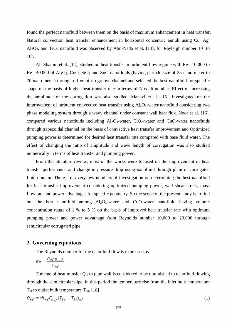
The rate of heat transfer Qnf to pipe wall is considered to be diminished to nanofluid flowing
through the semicircular pipe, in this period the temperature rise from the inlet bulk temperature
Tbi to outlet bulk temperature Tbo. [18]
(1)
299
Where is the mass flow rate of the flowing nanofluid through the pipe, is the
specific heat of the nanofluid at constant pressure. The bulk temperature Tb is taken as
(2)
The average heat transfer coefficient, hc is termed as [18]
(3)
Where Aw is the surface area of the circular pipe and ΔTm is the temperature difference
between the wall and the average bulk temperature of the fluid.
The average wall temperature Tw is given by
So the average Nusselt number is expressed as
(4)
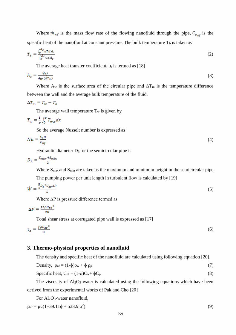
Hydraulic diameter Dh for the semicircular pipe is
Where Smax and Smin are taken as the maximum and minimum height in the semicircular pipe.
The pumping power per unit length in turbulent flow is calculated by [19]
(5)
Where ΔP is pressure difference termed as
Total shear stress at corrugated pipe wall is expressed as [17]
(6)
3. Thermo-physical properties of nanofluid
The density and specific heat of the nanofluid are calculated using following equation [20].
Density, ρnf = (1-ϕ)ρw + ϕ ρp (7)
Specific heat, Cnf = (1-ϕ)Cw+ ϕCp (8)
The viscosity of Al2O3-water is calculated using the following equations which have been
derived from the experimental works of Pak and Cho [20]
For Al2O3-water nanofluid,
µnf = µw(1+39.11ϕ + 533.9 ϕ2) (9)

300
Since there are no experimental results available in the literature for the viscosity of CuO-
water nanofluid at different volume fraction where base fluid is pure water, the correlation
developed by Corcione [21] has been used.
(10)
Where dbf is the equivalent diameter of the base fluid molecule,
In which M is the molecular weight of the base fluid, N is the Avogadro number, and ρbf is
the mass density of the base fluid. The thermal conductivity of Al2O3 – water is calculated by [20]
For Al2O3 – water,
Knf = Kbf (1.0021 + 7.3349ϕ) (11)
The thermal conductivity of CuO-water nanofluid has been calculated using the Maxwell
[22] model. The thermal conductivity of the nanofluid is given by,
(12)
4. Physical model
The Fluid domain is taken for numerical analysis with finite volume method (FVM) in both
circular plain pipe and the semicircular corrugated pipe having 12 millimeter diameter. 2-D
axisymmetric model is taken for better computation. The plain circular pipe length is chosen 1
meter long and the thermos-physical as well hydrodynamic behaviors are calculated between 800
millimeter and 900 millimeter distance from the inlet to ensure all the measured parameters are
in the fully developed flow region. For the semicircular corrugated pipe, 300 millimeter length is
taken and 1 millimeter circle radius with 12 millimeter wave length of the corrugation. In
semicircular corrugated pipe, first 30 millimeter is called the entry region, next 200 millimeter is
corrugated section and rest 70mm is exit region.
Fig. 1. Physical model of semi circular corrugated fluid domain(not up to scale).

301
5. Boundary conditions
The fluid domain has been characterized with velocity inlet and pressure outlet.5000 W/m2
constant heat flux is applied on the corrugated wall, the entry and the exit region of semicircular
pipe have no heat flux. Fluid is allowed to flow with uniform velocity through inlet having
constant temperature 300 K. k-ε turbulent model with realizable enhanced wall treatment is
selected for fluid dynamics behavior analysis through the corrugated domain. The fluid particles
are allowed to move freely with no slip condition and 5% turbulent intensity has been used.
Reynolds numbers have been implemented in terms of velocity of the fluid. Convective heat
transfer coefficient and the pressure difference are calculated through plain and corrugated pipe
with the increase of Reynolds number taking water and 1 %-5 % volume fraction of Al2O3-water
and CuO-water nanofluid as base fluid by using their different thermo-physical properties. In this
pressure velocity coupling, for pressure PRESTO, second order upwind for momentum, turbulent
kinetic energy, and turbulent dissipation rate have been applied in spatial discretization. The test
section for corrugated pipe is taken at 70 millimeter and 237 millimeter from inlet. In this section
the wall temperature, bulk temperature and the pressure at two test points are calculated using
user defined functions(UDF) in ‘CFD-post processing’.
6. Code validation & grid independence test
In order to investigate the thermophysical and hydrodynamic behavior for both plain and
corrugated pipe using Al2O3-water and CuO-water nanofluid commercial software ‘ANSYS-
fluent 12.0’ has been employed. Water is taken as the working fluid through the plain circular
pipe in order to numerically calculate the Nusselt number for the Reynolds number ranging from
10,000 to 20,000. Numerically found results of the present investigation show similarity with the
correlation for Nusselt number given by Notter and Sleicher[17].
The correlation given by Notter and Sleicher is:
Nu = 5 + 0.016 ReaPrb (7)
Where, a = 0.88 - and b = 0.33+0.5e(-0.6Pr)

302
Fig. 2. Code validation
Figure 2 shows good agreement between proposed code and the empirical correlation given
by ‘Notter and Sleicher.’
Grid independence test is conducted for the accuracy of the numerical simulations applied in
corrugated pipe. A fixed Reynolds number (Re=15,000) and water as base fluid are taken to
carry out the grid independence test. Diffreent element sizes has been applied to change the
number of elements and Nusselt number is calculated for particular grid number. Number of
elements are tested 14,228 , 28,138 , 32,803 , 43,568 , 48,574 and calculated Nusselt number is
observed decreasing at first but beyond 32,803 elements, the Nusselt numbers become almost
constant with the increase of elements.Therefore, 32,803 has been taken as the optimum grid for
the semicircular corrugated pipe. Figure 3 represents the grid independency for the semicircular
corrugated geometry.
Fig. 3. Grid independence test
7. Result & discussion
7.1 Effect of corrugation on heat transfer performance

303
For water, taken as base fluid through both circular and semicircular corrugated pipe the
effect of corrugation on heat transfer performance is analyzed. It shows improvement in heat
transfer rate due to corrugation as the flow pattern and mixing behavior changes. Figure 3 shows
improvement on heat transfer performance comparing with plain circular pipe due to the
turbulence at the near wall behavior. 34.81 % increase in heat transfer is obtained from the
corrugation shape at Reynolds number 18,000.
Fig. 4. Comparison of heat transfer enhancement for corrugation
7.2 Effect of corrugation on pumping power
Due to corrugation, pressure drops and frictional loss increases in corrugated pipe. The
required pumping power is expected to be increased in the corrugated pipe than plain pipe.
Pumping power requirement become higher in the semicircular pipe. Figure 5 represents
pumping power variations with Reynolds number for water as working substance through plain
and corrugated shape geometry. At Reynolds number 18,000 semicircular corrugated pipe
requires 99.125 % of extra pumping power than plain pipe for flowing water through the fluid
domain.
Fig. 5. Variation of pumping power due to corrugation

304
7.3 Effect of using nanofluid in heat transfer
In this present study, Al2O3-water and CuO-water nanofluid are used with 1 % - 5 % volume
fraction as the working fluid through the semicircular domain. As the volume concentration of
nanofluid increases, the thermal conductivity of the base fluid improves, Figure 6(A) & 6(B)
represents significant improvement in heat transfer performance due to nanofluid. The
improvement also occurs for a fixed volume fraction nanofluid with the increase of Reynolds
number. At Reynolds number of 20,000 the improvement occurs 26.39 % and 24.27 % at highest
volume concentration of Al2O3 and CuO than water.
Fig. 6. Heat transfer improvement for (A) Al2O3 ,(B)CuO nanofluid with Reynolds number.
7.4 Effect on pumping power using nanofluid
As the volume fraction of nanofluid increases, the requirement of pumping power increases
due to higer viscosity of the working fluid. Figure 7 and Figure 8 indicate that pumping power
for Al2O3 and CuO nanofluid have been increased with the volume fraction of nanofluid is
increased from 1 % to 5 %. Higher the volume fraction, higher the pumping power. At 5 %
volume fraction of both Al2O3-water and CuO-water nanofluid, the pumping power requires
60.49 % and 42.90 % more power in comparison with water through the semicircular corrugated
pipe in turbulent regime having Reynolds number 20,000.

305
Fig. 7. Pumping Power behavior on increasing Al2O3 nanofluid volume fraction.
Fig. 8. Pumping Power behavior on increasing CuO nanofluid volume fraction.
7.5 Effect on total wall shear stress for nanofluid
Frictional loss and pressure drop increase for the implementation of nanofluid in increased
volume fraction and Reynolds number. More frictional loss increases the total wall shear stress.
The total wall shear stress is calculated for two different nanofluid as well as for water. Figure 8
shows variation of total wall shear stress for semicircular corrugated pipe with Reynolds number
for 1 % to 5 % volume fraction. Higher total wall shear stress is expected from higher volume
fraction of nanofluid due to change in fluid flow behavior in terms of circulation, vortex
generation and turbulence. Figure 10 shows nonconventional behavior due to material property.
Al2O3-water nanofluid is exposed to more wall shear stress than CuO-water nanofluid except 2 %
volume fraction.

306
Fig. 9. Variation of total wall shear stress with Reynolds number in semicircular corrugated pipe.
Fig. 10. Effect on total wall shear stress with increasing volume fraction of nanofluid
7.6 Justification on pumping power for specific heat transfer performance
The present investigation is lead to find out the optimum pumping power for specific heat
transfer rate. Though heat transfer rate increases at higher volume fraction of nanofluid but
adversely it requires higher pumping power due to higher wall shear stress, pressure drop. Figure
11 refers to find out the optimum pumping power on specific heat transfer rate for 1 % - 5 %
volume fraction of CuO-water nanofluid comparing with water. 1 % volume fraction of CuO-
water nanofluid requires lower pumping power than water through semicircular corrugated pipe
at same increased heat transfer rate. For Al2O3-water nanofluid, 2 % volume fraction offers
lowest pumping power than water for the same fluid domain.

307
Fig. 11. Pumping Power optimization for CuO nanofluid (Tested range of heat transfer co
efficient 11000 W/m2K to 15000 W/m2K)
Both nanofluid have the ability to improve the heat transfer performance than water through
the semicircular corrugated pipe. Selecting the perfect nanofluid among two of them for this type
of corrugated pipe can be justified from Table 1 based on power advantage, mass flow and other
parameters.
Table 1. Comparison of two nanofluid performance with water through semicircular pipe
Working condition Working Fluid
Water 2 % Al2O3 1 % CuO
Density (kg/m3) 996 1040.61 1051.04
Viscosity (kg/m-s) 7.98e-04 8.99e-04 8.58e-04
Specific heat (J/kg-K) 4178 4126.955 4141.47
Requirement of heat transfer coefficient (W/m2K) 14000 14000 14000
Reynolds number (Re) 19000 18000 18000
Velocity (m/s) 1.522 1.546 1.470
Pressure drop (KPa/m) 13 13.5 12.49
Pumping Power(W/m) 9.84 8.62 8.54
Power advantage (W/m) _ 1.22 1.3
Power advantage (%) _ 12.39 % 13.21 %
Mass flow (kg/s) 0.11913 0.1264 0.12143
308
8. Conclusions
Semicircular corrugated pipe and nanofluid have been used to enhance the heat transfer
performance in this investigation. Corrugation in the pipe offers more pumping power due to
increased viscosity for flowing fluid through it. Nanofluid compensates the increased pumping
power in optimum level comparing with water. Al2O3-water and CuO-water nanofluid with 1 % -
5 % volume fraction are used to enhance the heat transfer rate as well as for finding out optimum
pumping power than water through the corrugated pipe. 2 % Al2O3-water and 1 % CuO-water
offer comparatively low pumping power to accomplish same heat transfer rate. Based on power
advantage, 1 % CuO- water nanofluid shows superior performance for enhanced heat transfer
and reduced pumping power than 2 % Al2O3-water through semicircular corrugated pipe. So 1 %
CuO may be the suitable solution for enhancing the forced convective heat transfer rate.
References
1. A.G. Ramgadia, A.K. Saha, Numerical study of fully developed flow and heat transfer in a
wavy passage, 2013, International Journal of Thermal Sciences, vol. 67, pp. 152-166.
2. G. Fabbri, Heat transfer optimization in corrugated wall channels, 2000, .International
Journal of Heat and Mass Transfer, vol. 43, no. 23, pp. 4299-4310.
3. Y. Sui, C.J. Teo, P.S. Lee, Y.T. Chew, C. Shu, Fluid flow and heat transfer in wavy
microchannels, 2010, International Journal of Heat and Mass Transfer, vol. 53, no. 13, pp.
2760-2772.
4. B. Sunden, I. Karlsson, Enhancement of heat transfer in rotary heat exchangers by
streamwise-corrugated flow channels, 1991, Experimental thermal and fluid science, vol. 4,
no. 3, pp. 305-316.
5. P. Naphon, Laminar convective heat transfer and pressure drop in the corrugated channels,
2007, International communications in heat and mass transfer, vol. 34, no. 1, pp. 62-71.
6. H.A. Mohammed, A.M. Abed, M.A. Wahid, The effects of geometrical parameters of a
corrugated channel with in out-of-phase arrangement, 2013, International Communications in
Heat and Mass Transfer, vol. 40, pp. 47-57.
7. P. Naphon, Effect of corrugated plates in an in-phase arrangement on the heat transfer and
flow developments, 2008, International Journal of Heat and Mass Transfer, vol. 51, no. 15,
pp. 3963-3971.
8. M.M. Ali, S. Ramadhyani, Experiments on convective heat transfer in corrugated channels,
1992, EXPERIMENTAL HEAT TRANSFER An International Journal, vol. 5, no. 3, pp.
175-193.

309
9. S.E.B. Maı̈ga, C.T. Nguyen, N. Galanis, G. Roy, Heat transfer behaviours of nanofluids in a
uniformly heated tube, 2004, Superlattices and Microstructures, vol. 35, no. 3, pp. 543-557.
10. A.K. Santra, S. Sen, N. Chakraborty, Study of heat transfer augmentation in a differentially
heated square cavity using copper–water nanofluid, 2008, International Journal of Thermal
Sciences, vol. 47, no. 9, pp. 1113-1122.
11. A. Adil, S. Gupta, P. Ghosh, Numerical prediction of heat transfer characteristics of
nanofluids in a minichannel flow, 2014, Journal of Energy.
12. B. Farajollahi, S.G. Etemad, M. Hojjat, Heat transfer of nanofluids in a shell and tube heat
exchanger, 2010, International Journal of Heat and Mass Transfer, vol. 53, no. 1, pp. 12-17.
13. E. Abu-Nada, Z. Masoud, A. Hijazi, Natural convection heat transfer enhancement in
horizontal concentric annuli using nanofluids, 2008,.International Communications in Heat
and Mass Transfer, vol. 35, no. 5, pp. 657-665.
14. A.N. Al-Shamani, K. Sopian, H.A. Mohammed, S. Mat, M.H. Ruslan, A.M. Abed, Case
Studies in Thermal Engineering, 2014.
15. S.A. Manavi, A. Ramiar, A.A. Ranjbar, Turbulent forced convection of nanofluid in a wavy
channel using two phase model, 2014, Heat and Mass Transfer, vol. 50, no. 5, pp. 661-671.
16. S. Noor, M.M. Ehsan, M.S. Mayeed, A.K.M. Sadrul Islam, Convective Heat Transfer and
Pumping Power Requirement Using Nanofluid for the Flow Through Corrugated Channel,
2015, In ASME 2015 International Mechanical Engineering Congress and Exposition, pp.
V08AT10A017-V08AT10A017.
17. M.N. Ozisik, Forced convection for flow inside ducts, 1985, Heat transfer: a basic approach,
ch. 7, pp.281-347.
18. M.S. Fadl, A numerical simulation of heat transfer performance using different corrugated
surface shape, 2013, Proceedings of ICFD11. International Conference of Fluid Dynamics.
19. Y.A. Cengel, A.J. Ghajar, Heat and mass transfer (a practical approach, SI version), 2011, ch.
8, pp. 466-518.
20. B.C. Pak, Y.I. Cho, Hydrodynamic and heat transfer study of dispersed fluids with submicron
metallic oxide particles, 1998, Experimental Heat Transfer an International Journal, vol. 11,
no. 2, pp. 151-170.
21. M. Corcione, Heat transfer features of buoyancy-driven nanofluids inside rectangular
enclosures differentially heated at the sidewalls, 2010, International Journal of Thermal
Sciences, vol. 49, no. 9, pp. 1536-1546.
22. J.C. Maxwell, A treatise on electricity and magnetism, 1881, vol. 1.

310
Nomenclature
Ac
Aw
Cp
Dh
D
k
Q
q
T
U
L
Cross-sectional area of pipe,
m2
Sufrace area of pipe, m2
Specific heat, J. kg-1. K-1
Hydraulic diameter, m
Diameter, m
Thermal conductivity, W. m-1.
K-1
Heat transfer, W
Heat flux, W.m-2
Temperature, K
Velocity at inlet, m. s-1
Length of the test section, m
Greek symbols
ρ
τ0
ν
µ
Density, Kg.
m-3
Total wall
shear stress,
Pa
Solid volume
fraction
Kinematic
viscosity, m2.
s-1
Dynamic
viscosity, Kg.
m-1. s-1
Dimensionless parameter
Nu
Re
Pr
Subscripts
av
i
o
bf
nf
max
min
w
p
average
value
value at
inlet
value at
outlet
base
fluid
nanofluid
maximun
value
minimum
value
water
nano
Nusselt number
Reynolds number
Prandtl number
friction factor

311
(metal)
particle
f