Embed Size (px)
Citation preview
118
AMSE JOURNALS-2016-Series: Modelling A; Vol. 89; N°1; pp 118-129
Submitted July 2016; Revised Oct. 15, 2016, Accepted Dec. 10, 2016
Dynamic Performance Analysis of the Induction Motor Drive Fed by
Current-Source Based on Ansoft
Zhen Guo1,2 *, Jiasheng Zhang1, Changming Zheng1 and Zhenchuan Sun1
1College of Information and Control Engineering, China University of Petroleum, Qingdao,
266580, China ([email protected])
2College of automation engineering, Qingdao University of Technology, Qingdao 266520,
China
Abstract:
The dynamic performance of induction motor fed by current-source are analyzed in this
paper based on Ansoft. The theory of symmetrical components is used to derive the
fundamental formula of induction motor fed by current-source and the co-simulation
method combined Ansoft/Maxwell 2D and Ansoft/Simplorer is studied in detail. The
characteristics of induction motor fed by current-source in different working condition are
analyzed. The results indicate the changes in the magnetic field and operating performance
variations of the induction motor fed by current-source compare with that fed by
voltage-source. The conclusions provide a reference for theoretical research of induction
motor body and optimal design of its control system.
Keywords: Co- simulation model, finite element analysis, current-source, induction motor
1. Introduction
In the variable speed drive systems, induction motors are widely used in industrial application
[1,2]. Induction motor drives employ mostly a voltage-source inverter (VSI) topology. However,
its application is restricted by poor load current limitation capability, dynamic response
retardation and four-quadrant operation limitation. Contrarily, the current source inverter (CSI) is
a strong candidate for induction motor drive systems due to its inherent advantages such as
perfect over-current ability, good dynamic response and regenerative capability [3,4]. These
119
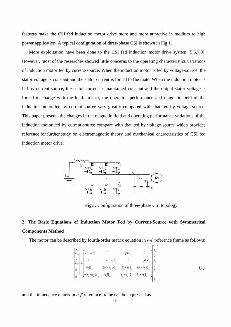
features make the CSI fed induction motor drive more and more attractive in medium to high
power application. A typical configuration of three-phase CSI is shown in Fig.1.
More exploitation have been done to the CSI fed induction motor drive system [5,6,7,8].
However, most of the researches showed little concerns to the operating characteristics variations
of induction motor fed by current-source. When the induction motor is fed by voltage-source, the
stator voltage is constant and the stator current is forced to fluctuate. When the induction motor is
fed by current-source, the stator current is maintained constant and the output stator voltage is
forced to change with the load. In fact, the operation performance and magnetic field of the
induction motor fed by current-source vary greatly compared with that fed by voltage-source.
This paper presents the changes in the magnetic field and operating performance variations of the
induction motor fed by current-source compare with that fed by voltage-source which provides
reference for further study on electromagnetic theory and mechanical characteristics of CSI fed
induction motor drive.
Ud
VT1 VT
VT4 VT6 VT2
Id
3
VT5
iU
C
iW
iVM
L
Fig.1. Configuration of three-phase CSI topology
2. The Basic Equations of Induction Motor Fed by Current-Source with Symmetrical
Components Method
The motor can be described by fourth-order matrix equation in α-β reference frame as follows:
(1)
and the impedance matrix in α-β reference frame can be expressed as
0 0
0 0
( ) ( )0
( ) ( )0
s
s s s so s sro
ss s so s sros
s sro s sl sro r s ro s sl ror
s sl sro s sro s sl ro r s ro
r
IR j L j MU
R j L j M IU
j M M R j L LI
M j M L R j L
I
120
0 0
0 0
( ) ( )
( ) ( )
s s so s sro
s s so s sro
s sro s sl sro r s ro s sl ro
s sl sro s sro s sl ro r s ro
R j L j M
R j L j MZ
j M M R j L L
M j M L R j L
(2)
Assume that the stator current is unsymmetrical sI
, sI
can be replaced by the positive
sequence component PI
and negative sequence component NI
. They are related by the following
equation:
s P N
s P N
I I I
I j I j I
(3)
Similarly, the relation of the rotor current with symmetrical component method is described as
follows:
1 1r f
r b
I I
j jI I
(4)
Impedance matrix pnZ in symmetrical component coordinates results from Z , so
0 0
0 0
( ) 0 0
0 ( ) 0 ( )
s s so s sro
s s so s sro
s r sro r s ro
s r sro r s r ro
pn
R j L j M
R j L j M
j M R j L
j M R j L
Z
(5)
The voltage equation of the induction motor in symmetrical coordinates can be expressed as
0 0
0 0
( ) 0 0
0 ( ) 0 ( )
PP
s s so s sro
NN s s so s sro
s r sro r s roff
s r sro r s r ro
bb
U IR j L j M
R j L j MU I
j M R j LU I
j M R j L
U I
(6)
The positive sequence component of the stator and the rotor can be an independent coordinate.
Similarly, the negative sequence component can be too. The second line and the third line of
equation (6) are interchanged, so equation (6) is now transformed into equation (7)

121
0 0
( ) ( ) 0 0
0 0
0 0 ( ) ( )
PP
s s so s sro
ff s r sro r s r ro
s s s roNN
s r sro r s r
bb
U IR j L j M
j M R j LU I
R j j LU I
j M R jU I
(7)
The rotor voltages of the squirrel-cage induction motor is zero, so 0f bU U
.When the stator
current is symmetrical, the negative component 0N bI I
, equation (7) can be changed into
( ) ( )0
Ps s so s sroP
s r sro r s r rof
R j L j M IU
j M R j LI
(8)
so
( )
0 ( ( ) )
P fPs s so s sro
P fs sro r s r ro
U R j L I j M I
j M I R j L I
(9)
When the stator PI
is a known value, the rotor current is as follows:
( )
s sro s sro
f P P
r s r ro r sl ro
j M j MI I I
R j L R j L
(10)
Then the stator voltage can be written as
(11)
And
AP
3I I
(12)
The equation of the electromagnetic torque, output power and the stator flux can be derived based
on the equations from (9) to (12).
3. The establishment of finite element model
Analysis and simulation modeling techniques in induction motors can be classified in two
categories. One is electrical parameter model, the other is to build the motor model by using
motor design software. The method of the electrical parameter model can observe the electrical
PP
P
( )
( ) ( )
fs s so s sro
s sroP
s s so
r sl ro
U R j L I j M I
j MR j L I I
R j L
122
characteristics of the induction motor, but the internal magnetic field of the motor cannot be
obtained. By using motor design software to establish the motor model can get part of the
electrical characteristics and the internal magnetic field, but it is unfitted to the complex electrical
system. So the co-simulation method is explored in this paper which meet the demand of the
complex the drive system. The Ansoft/Maxwell 2D and Ansoft/Simplorer are used to build model
of the induction motor fed by current-source to explore the characteristics variation compare with
that fed by voltage-source. An four-pole induction motor is presented in this paper. The
parameters of tested motor are listed in Table I.
Table I. Parameters for tested motor
Parameters Values
Rated Shaft Power 11 KW
Rated Phase Voltage 380 V
Rated Frequency 50Hz
Synchronous Speed 1500r/min
Number of The Pole Pairs 2
Number of Stator Slots 36
Number of Rotor Slots 26
Outer Diameter of Stator 260mm
Inner Diameter of Stator 170mm
Outer Diameter of Rotor 169mm
Inner Diameter of Rotor 60mm
Core Length 155mm
In accordance with the model requirements, the material properties of the motor are set
including stator winding, stator core and rotor core and other parts of the motor. Because of the
two dimensional analysis of the motor, the vector magnetic field in Z direction is set to 0. In the
finite element model of induction motor, no-load speed and rated speed of the motor are set 1500
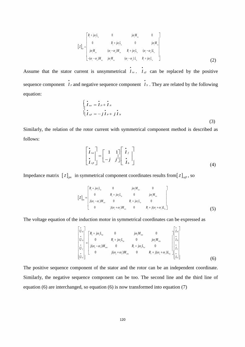
rpm and 1462 rpm respectively. According to the mechanical parameters of the motor,the finite
element model is created in Ansoft /RMxprt which is shown in Fig.2.
123
Fig.2. Finite element model of tested motor
4. The co-simulation method combined Ansoft/Maxwell 2D and Ansoft/Simplorer
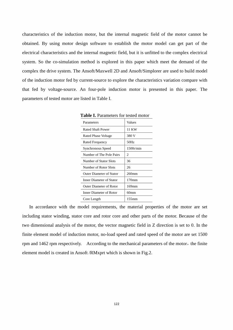
Importing the finite element model and building the peripheral circuit and relevant load in
Ansoft/simplorer,the co-simulation system is built which is shown in Fig.3. The Phase A in and
Phase A out of the motor represent both ends of the A phase winding, Phase B in and Phase B out
represent the ends of the B phase winding and Phase C in and Phase C out represent both ends of
the C phase winding. I1, I2 and I3 are three-phase symmetrical current-source. The A, B, C
three-phase in ports are connected to the three-phase current-source. The A, B, C three-phase out
ports are connected together to form the star structure of the stator winding. MotionSetup1_in and
MotionSetup1_out ports are motor mechanical port. The inertia MASS_ROT1 and load torque
F_ROT1 are connected to MotionSetup1_out. The load torque are added by using STEP1 and
STEP2. MotionSetup1_in is grounded.
I1
I3
I2
PhaseA_In
PhaseC_In
PhaseB_InPhaseA_out
PhaseB_out
PhaseC_out
MotionSetup1_in MotionSetup1_out
STEP1
STEP2 SUM1
ROTB_ROT1MASS_ROT1
F_ROT1
Fig.3. The co-simulation model of the induction motor fed by current-source
5. Simulation results and analysis
When the induction motor is fed by current-source, the input is the stator three-phase
currents and the stator currents are constant when load is varying. At start-up, the induction motor
under no load is fed by rated current at 50HZ. A rated load is 70N.m which is applied after
124
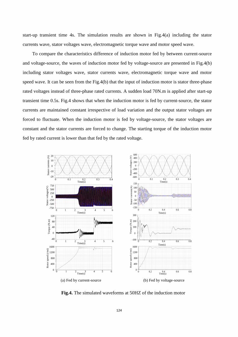
start-up transient time 4s. The simulation results are shown in Fig.4(a) including the stator
currents wave, stator voltages wave, electromagnetic torque wave and motor speed wave.
To compare the characteristics difference of induction motor fed by between current-source
and voltage-source, the waves of induction motor fed by voltage-source are presented in Fig.4(b)
including stator voltages wave, stator currents wave, electromagnetic torque wave and motor
speed wave. It can be seen from the Fig.4(b) that the input of induction motor is stator three-phase
rated voltages instead of three-phase rated currents. A sudden load 70N.m is applied after start-up
transient time 0.5s. Fig.4 shows that when the induction motor is fed by current-source, the stator
currents are maintained constant irrespective of load variation and the output stator voltages are
forced to fluctuate. When the induction motor is fed by voltage-source, the stator voltages are
constant and the stator currents are forced to change. The starting torque of the induction motor
fed by rated current is lower than that fed by the rated voltage.
Time(s)
-10
0
10
20
-20
Sta
tor
cu
rren
ts (
A)
0 0.1 0.2 0.3 0.4
0 1 2 3 4 5 6 Time(s)
0
400
800
1200
1600
Ro
tor
speed (
r/m
i) T
orq
ue (
N.m
)
Time(s)
0
40
80
120
-400 1 2 3 4 5 6
Sta
tor
vo
ltag
es(
V)
Time(s)0 1 2 3 4 5 6
500
750
0
250
-250
-500
-750
Time(s)0 0.1 0.2 0.3 0.4
-200
0
200
600
-400
Sta
tor
vo
ltag
es
(V)
400
-600
Sta
tor
cu
rren
ts(A
)
0 0.2 0.4 0.6 0.8
Time(s)
0
100
150
-100
-150
50
-50
To
rqu
e (
N.m
)
0
100
200
300
-100
Time(s)
0 0.2 0.4 0.6 0.8
0
400
800
1200
1600
Ro
tor
speed (
r/m
i)
Time(s)0 0.2 0.4 0.6 0.8
(a) Fed by current-source (b) Fed by voltage-source
Fig.4. The simulated waveforms at 50HZ of the induction motor
125
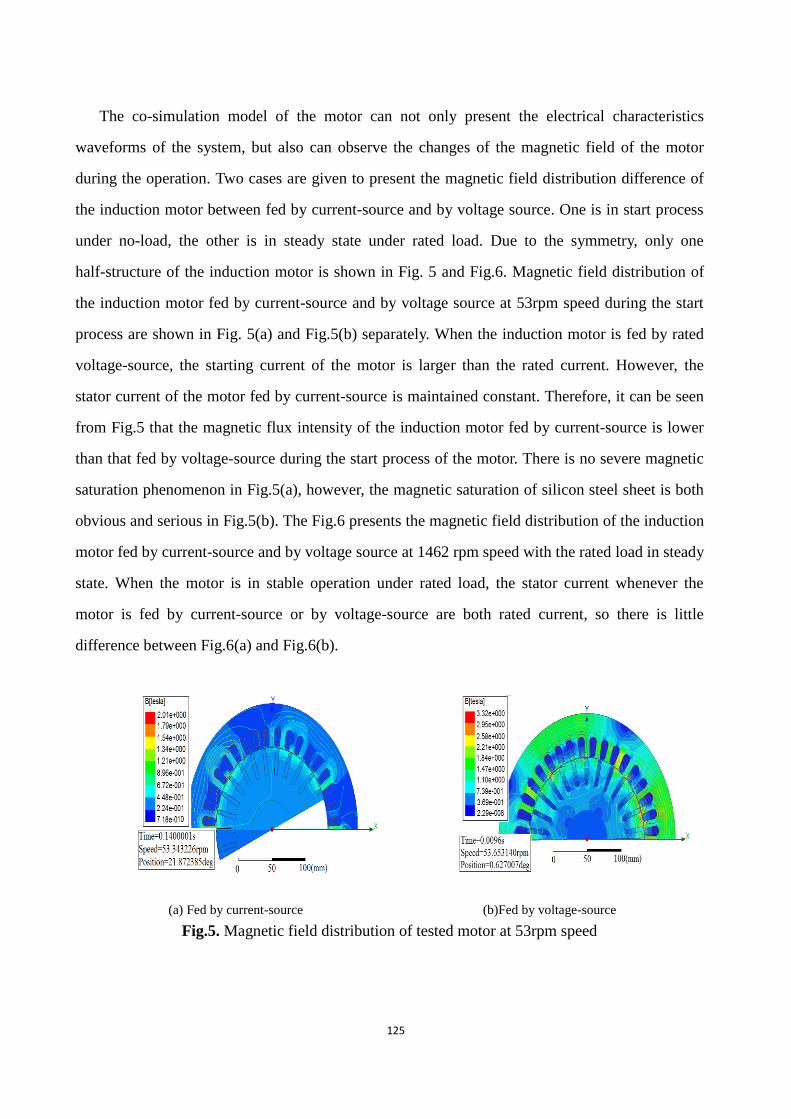
The co-simulation model of the motor can not only present the electrical characteristics
waveforms of the system, but also can observe the changes of the magnetic field of the motor
during the operation. Two cases are given to present the magnetic field distribution difference of
the induction motor between fed by current-source and by voltage source. One is in start process
under no-load, the other is in steady state under rated load. Due to the symmetry, only one
half-structure of the induction motor is shown in Fig. 5 and Fig.6. Magnetic field distribution of
the induction motor fed by current-source and by voltage source at 53rpm speed during the start
process are shown in Fig. 5(a) and Fig.5(b) separately. When the induction motor is fed by rated
voltage-source, the starting current of the motor is larger than the rated current. However, the
stator current of the motor fed by current-source is maintained constant. Therefore, it can be seen
from Fig.5 that the magnetic flux intensity of the induction motor fed by current-source is lower
than that fed by voltage-source during the start process of the motor. There is no severe magnetic
saturation phenomenon in Fig.5(a), however, the magnetic saturation of silicon steel sheet is both
obvious and serious in Fig.5(b). The Fig.6 presents the magnetic field distribution of the induction
motor fed by current-source and by voltage source at 1462 rpm speed with the rated load in steady
state. When the motor is in stable operation under rated load, the stator current whenever the
motor is fed by current-source or by voltage-source are both rated current, so there is little
difference between Fig.6(a) and Fig.6(b).
(a) Fed by current-source (b)Fed by voltage-source
Fig.5. Magnetic field distribution of tested motor at 53rpm speed

126
(a) Fed by current-source (b) Fed by voltage-source
Fig.6. Magnetic field distribution of tested motor at 1462rpm speed
6. Conclusion
The dynamic performance of the induction motor fed by current-source are analyzed in this
paper. The co-simulation system combined Ansoft/Maxwell 2D and Ansoft/Simplorer is built.
The simulation results indicate the changes not only in the operating performance but also in
magnetic field of the induction motor fed by current-source compare with that fed by
voltage-source. The conclusions provide a reference for theoretical research of induction motor
body and optimal design of its control system.
Nomenclature
sR ,rR stator , rotor resistance
soL ,roL stator self-inductance, rotor self-inductance
sroM mutual inductance of the motor
sU
, sU
α-axis and β-axis components of stator voltages
sI
, sI
α- axis and β-axis components of stator current
rI
, rI
α- axis and β-axis components of rotor current
PI
, NI
positive sequence and negative sequence components of stator current in
symmetrical coordinates
127
fI
, bI
positive sequence and negative sequence components of rotor current in symmetrical
coordinates
AI
A phase of stator current
s ,r ,
sl synchronous , rotor and slip speed in electrical radians/second.
Z
, pn
Z αβ-axis and symmetrical coordinate impedance matrix
PU
, fU
positive sequence component of stator voltage and rotor voltage in symmetrical
coordinates
bU
, NU
negative sequence component of stator voltage and rotor voltage in symmetrical
coordinates
References
[1] Bimal K.Bose, Modern power electronics and AC drives.[M]. Beijing:China machine
press,2013.
[2] P. Enjeti, P. Ziogas, and J. Lindsay, “A current source PWM inverter with instantaneous
current control capability,” IEEE Trans. Ind Applicat., vol.27, pp.643–893, May/June
1991.
[3] BinWu, High-power converters and AC Drives. Piscataway, NJ: Wiley-IEEE Press, 2006.
[4] Behrooz Mirafzal and Nabeel A.O. Demerdash, “A Nonlinear Controllerfor Current Source
Inverter Induction Motor Drive Systems,” IEEE Trans. On Electric Machines and Drives,
vol.3 No. 2, pp.1491 - 1497, 2003.
[5] A. Nabae, I. Takahasi, and H. Akasi, “A Neutral Point Clamped PWM Inverter,” in Conf.
Rec. IEEE-IAS Annu. Meeting, 1980, pp.530–536.
[6] P. M. Bhagwat and V. R. Stefanovic, “Generalized Structure of a Multilevel PWM
Inverter,” IEEE Trans.Ind. Applicat, vol. IA-19, pp.1057–1069, Nov./Dec.1983.
[7] R. J. Kerkman, “Twenty years of PWM AC Drives when Secondary Issues Become
Primary Concerns,” in Proc. IECON’96 Conf., Taipei, Taiwan, R.O.C., pp. LVII–LXIII.
Aug. 1996.
128
[8] Seyed Hamid Shahalami, “Special Proposed Hysteresis Control Method of Current Source
Inverter Asynchronous Drives”, IEEE 1st Power Electronic & Drive Systems
&Technologies Conference, pp.235-242, 2010.
[9] Aleksandar Nikolic, Borislav Jeftenic, “Different Methods for Direct Torque Control of
Induction Motor,” Wseas Transactions on Circuits and Systems, Volume 7, pp.739 - 748,
2008.
[10] Morawiec, Zbigniew Krzeminski, Arkadiusz Lewicki, “Voltage multiscalar control of
induction machine supplied by current source converter,” IEEE, pp.3119-3124, 2010.
[11] J. Espinoza and G. Jos, “Current-source converter on-line pattern generator switching
frequency minimization,” IEEE Trans. Ind. Electron.,vol.44, pp.198–206, Apr. 1997.
[12] A. R. Beig and V. T. Ranganathan, “A novel CSI-fed induction motor drive,” IEEE Trans.
Power Electron., vol.21, no. 4, pp.1073– 1082, Jul. 2006.
[13] A. M. Trzynadlowski, N. Patriciu, F. Blaabjerg, and J. K.Pedersen, “A Hybrid, Current
Source/Voltage Source Power Inverter Circuit,” IEEE Trans. Power Electron., vol.16, no. 6,
pp.866-871, Nov. 2001.
[14] R. Emery and J. Eugene, “Harmonic Losses in LCI fed Synchronous Motors,” IEEE Trans.
Ind. Appl., vol. 38, no. 4, pp. 948–954, Jul./Aug. 2002.
[15] D. Banerjee, “Load commutated SCR current source inverter fed induction motor drive
with sinusoidal motor voltage and current,” Ph.D. dissertation, Dept. Electr. Eng., Ind. Inst.
Sci. (IISc), Bengaluru, India, Jul. 2008.
[16] B.Wu, S. Dewan, and G. Slemon, “PWM CSI Inverter for Induction Motor Drives,” IEEE
Trans. Ind. Applicat., vol.28, pp.317–325, Jan./Feb. 1992.
[17] A. G. Yepes, F. D. Freijedo, J. Doval-Gandoy, O. Lopez, J. Malvar, and P.
Fernandez-Comesana, “Effects of discretization methods on the performance of resonant
controllers,” IEEE Trans. Power Electron., vol.25, no. 7, pp. 1692–1712, Jul. 2010.
[18] J. Hu and B. Wu, “New integration algorithms for estimating motor flux over a wide speed
range,” IEEE Trans. Power Electron., vol. 13, no. 5,pp. 969–977, Sep. 1998.
[19] Seyed Hamid Shahalami, “Special Proposed Hysteresis Control Method of Current Source
129
Inverter Asynchronous Drives,” IEEE 1st Power Electronic & Drive Systems
&Technologies Conference, pp.235-242, 2010.
[20] B. Bahrani, S. Kenzelmann, and A. Rufer, “Multivariable-PI-based DQ current control of
voltage source converters with superior axes decoupling capability,” IEEE Trans. Ind.
Electron., vol. 58, no. 7, pp.3016–3026, Jul. 2011.
[21] Yu Xiong, Danjiang Chen, Xin Yang, Changsheng Hu and ZhongchaoZhang, “Analysis
and Experimentation of A New Three-phase Multilevel Current-Source Inverter,” IEEE
Trans. On Telecommunications Energy Conference, Vol.1, pp.548-551, 2004.
[22] Pramod Agarwal, V.K. Verma and A.K. Pandey,“Performance Evaluation of a
Self-commutating CSI-fed Induction Motor Drive for Different Operating Conditions,
IETE Journal of Research, Vol.54, Issue 4, pp.227-238,July/Aug. 2008.
[23] Adrian Schiop and Daniel Trip, “Analysis of the Trapezoidal Modulation for Current
Source Inverters,” IEEE Trans. On Signals, Circuits and Systems, Vol.2, pp. 1-4, 2007.
[24] P. Agarwal and V.K. Verma, “Parameter Coordination of Microcomputer Controlled
CSI-fed Induction Motor Drive”, IE (I) Journal – EL, Vol.88, pp.25-34, December 2007.
[25] Hak-Jun Lee, Sungho Jung and Seung-Ki Sul, “Analysis and Experimentation of A New
Three-phase Multilevel Current-Source Inverter,” IEEE Trans. On Telecommunications
Energy Conference, Vol.1, pp.1364-1370, 2011.
[26] Pramod Agarwal, A.K. Pandey and V.K. Verma, “Performance Investigation of Modified
Self-commutated CSI-fed Induction Motor Drive, Asian Power Electronics Journal, Vol.3,
No.1, pp.21-29, Sept 2009.