Embed Size (px)
Citation preview

PERFORMANCE EVALUATION OF A
LOW PRESSURE WATER MIST SYSTEM IN A
MARINE MACHINERY SPACE WITH OPEN DOORWAY
BY Jerome S. Pepi
Grinnell Corporation Research and Development Center
Cranston, RI 02910
Prepared for Halon Options Technical Working Conference
Sponsored By University of New Mexico
Sheraton Old Town Albuquerque, New Mexico
May 9-1 1, 1995
HOTWC.95 423

PERFORMANCE EVALUATION OF A
LOW PRESSURE WATER MIST SYSTEM INA
MARINE MACHINERY SPACE WITH OPEN DOORWAY
BY Jerome S. Pepi
Grinnell Corporation
Introduction
Grinnell has completed a second series of large scale fire tests involving the evaluation of the A uaMist, low pressure (12 bar), impinging jet nozzle, water mist deluge system in a 500m simulated machinery space with a 4m2 open doorway. The first series of tests are described in Reference 1. Both series of evaluations were based on the fire test protocols recommended by the International Maritime Organization (IMO) in their “Interim Test Method for Fire Testing Evaluating Water-Based Fire-Extinguishing Systems for Machinery Spaces of Category A and Cargo Pump-Rooms”, which existed at the time.
4
The first series of tests were conducted in April of 1994 with the bottom of the 2m x 2m doorway located at the building floor level. The second series of tests were conducted in August of 1994 with the bottom of the 2m x 2m doorway located 0.5m above the building floor level. The bottom of the doorway was raised to more closely simulate a marine installation in which the air inlet draft through the open doorway could not occur in the bilge area beneath the machinery space floor plates. Details of the second test series are given in Reference 2.
During the 39th meeting of the IMO Fire Protection Sub-committee last July, certain tests were added to the IMO machinery space protocol. These included 0.5m2 heptane and lubrication oil pan fires concealed within the bilge area under the engine block as well as a 0.1m2 heptane pan fire shielded underneath a lm wide overhang at the side of the engine block. The low pressure system consisting of overhead mounted AquaMist AM10 nozzles was not able to extinguish these fires. The reasons, which are primarily related to the general principles of fire extinguishment by water mist, are presented in the Discussion section.
Nonetheless, presented in this paper are the results of 21 tests which have successfully demonstrated the capability of an overhead, low pressure water mist system to extinguish a wide variety of hydrocarbon pool, spray, cascading pool as well as combination Class A and B frres representative of those which might occur in a machinery space.
424 HOTWC.95

Page 2
Description of AquaMist Nozzles
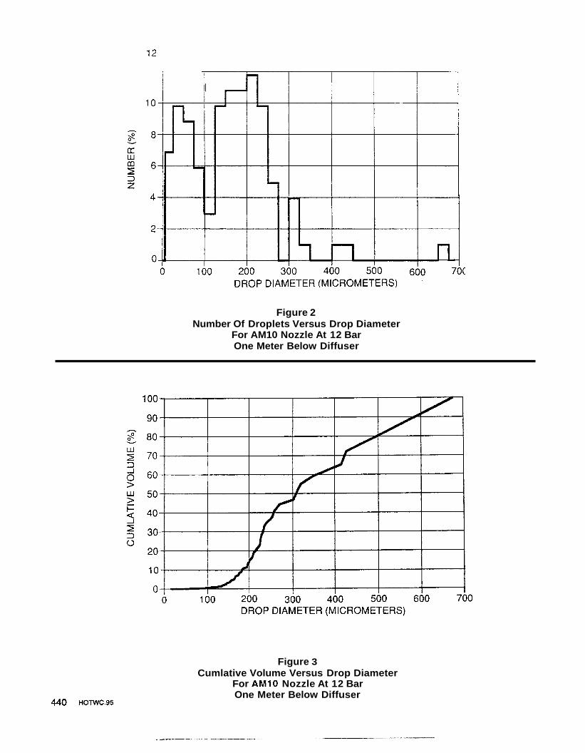
The AM10 AquaMist Nozzle utilized in the marine machinery space fire tests being reported on is illustrated in Figure 1. The nozzle K-factor is nominally 3.5 (lpmhar), the smallest diameter within the nozzle is nominally 2.3 mm and the strainer perforation diameter is specified at nominally 1.5 mm. In an actual installation, corrosion resistant piping and a suitable mainline strainer would be required for use with the AquaMist nozzles. The frame material of the nozzles is cast from ASTM A-743 alloy CF-8M, which is considered to be the cast equivalent of wrought Type 3 16 stainless steel. The inlet strainer, orifice insert and diffuser are fabricated from Type 3 16 stainless steel. At the nominal flowing pressure of 1 1.7 bar utilized throughout the test series, the flow rate per nozzle is about 12 lpm. Figures 2 and 3 show representative data on number of droplets and cumulative volume versus drop diameter, at 12 bar, one meter below the spherical nozzle diffuser (patents pending).
Approximately 10% of the AMlO’s droplets, which compromise about 50% of the volume flow, consists of droplets greater than 300 microns. These relatively large, high momentum droplets are used to help entrain the finer droplets and carry them into the combustion zone. They also provide surface cooling and extinguishment of Class A combustibles by direct wetting. At lm below the nozzle, the pattern is filled to about 1.4m in diameter, when sprayed in the open. When sprayed in an array, the pattern expands and the water droplets are distributed around the space according to the size of the droplets (e.g., smallest being the most mobile).
Description of Test Set-Up
Figure 4 illustrates plan and front wall elevation views of the 10m x 10m x 5m hgh enclosure used for this test series, which was conducted in the 18m wide x 22m long (6000m3) main fire test hall at the Swedish National Testing and Research Institute (SP), in Boras, Sweden. Figure 4 also provides an overlay of the AM10 nozzle locations.
The diesel engine mock-up along with the locations of the fuel spray jets and pool trays are illustrated in Figures 5 and 6 . The engine mock-up was lm x 3m x 2.5m high, and it was constructed of sheet steel with a nominal thickness of 5mm. When this test series was performed, in August of last year, the mock-up was in accordance with the International Maritime Organization (IMO) machinery space qualification test requirements which existed at that time. However, in December of 1994, the height of the mock-up was changed from 2.5m to 3m. The mock-up was fitted with: two steel tubes (2mm wall thickness) having an outside diameter of 0.3m and a length of 3m that simulate exhaust manifolds; along with, an adjacent 0.7m wide by 3.5m long solid steel plate. The floor plates surrounding the engine block were 5mm thick sheet steel, and they were spaced approximately 0. lm away from the sides of the block. The mock-up is considered to simulate a small diesel engine or part of a large diesel engine.
HOlWC.95 425

Page 3
A three square meter fuel tray was located on top of the engine mock-up and a 4 square meter tray was located at the bottom of the simulated 0.75m high bilge area, beneath the engine mock-up. When oil pool fues were set-up in the top tray, they were pre-filled with water to establish a free-board height of about 50mm. Figure 6 schematically illustrates horizontally orientated fuel jets on the top and at the side of the engine mock- up. An exposed 45" upward directed fuel jet, on top of the engine mock-up, was also evaluated.
The 15mm diameter by lm high steel pipe (Obstruction Rod), located on top of the engine mock-up, provided a hot spot re-ignition point for the adjacent pressurized fuel jet, as did the top tube and the tray area. The solid plate at the right side with its angle supports, and the lower tube along the side of the engine mock-up provided multiple re- ignition points for the right side fuel jet, in addition to shielding of the fuel spray. The top tube also tended to provide some shielding of the pool tray at the top of the engine mock-up.
The piping arrangement consisted of a dual feed gridded piping system, which was established to minimize the differences between the flow rates of individual nozzles and to allow water flow from all nozzles at about the same time. Two supply hoses were connected near the centers of the 50mm mains located on opposite sides of the grid, 10m apart. Five 40 mm cross connections spaced 2m apart were made between the mains to serve as the feed lines to the individual nozzles. At a 2m spacing along the cross connections, a 25mm arm-over was installed with about a 0.5m drop to just above the ceiling. At that point, the drops were reduced to 15- diameter down to the nozzles. The nozzles were located at either a 0.2m or 0.9m diffuser to ceiling distance, and flat escutcheon plates were installed around the drop nipples to seal off the penetration through the ceiling. A 15mm drop was made from the front 40mm cross connection down to the two nozzles which were positioned 0.3m inside of the doorway, 0.3m in from the left and right edges and 0.5m above the top of the opening.
The two nozzles over the doorway were used to minimize the intake of fresh air into the enclosure. A similar effect could be obtained by installing the ceiling nozzles at a closer spacing and eliminating the nozzles over the doorway. However, the above described system was considered to be the more energy efficient.
The pipework was fitted with a pressure tap located near the center of the array and connected back to a gauge at the pump location so that the operator could immediately adjust the pump output in response to any pressure changes. The above described piping was not sized at the minimum required for an actual system. Rather, it was sized on the basis of maintaining essentially the same residual (flowing) pressure for all nozzles.
Both of the thermocouples were fabricated from 0.25mm chromel-alumel thermocouple wire that was welded together at the sensing points. The ceiling gas thermocouple was located about 25mm below the ceiling, while the gas thermocouple at the right side of the engine mock-up was located about 0.55mm below the 0.7m wide solid plate.
426 HOTWC.95

Page 4
The thermocouple wire, from the ceiling down to the 0.7m wide plate, at right side of the engine mock-up, was contained within 25mm steel pipe for protection.
Total Heat Release Rates
During the test series described in the following section, a variety of pool and spray fire tests were conducted. Arrangements could not be made for calorimeter measurement of the Total Heat Release Rates (Total HRR). Consequently, it was necessary to estimate the Total HRR values utilizing a heat of combustion of 39MJ/kg for the diesel oil and 44.6MJ/kg for the heptane. The mass flow rates of the pool fires were calculated using Reference 3 and, the buring efficiency was assumed to be 85%. For the spray fires, the mass flow rates given in Table 2 were used.
Fire Scenarios
The fire scenarios were chosen by the IMO to represent possible fires in an enclosure with a hydrocarbon fueled engine. Fires might occur, for example, if oil from a pipe break contacts a hot surface in the exhaust system or, if a leak forms a spill that ignites. A combination of these two scenarios is also possible which was reflected in the tests. To simulate a combination of a spill fire and a fire involving Class A material, a test was conducted with a small wood crib placed in a tray with heptane. To simulate hot surfaces, such as exhaust ducts or manifolds, one of the selected fire scenarios involved a steel plate, situated on the top of the simulated engine, that was heated with a propane gas burner to at least 350°C prior to the start of the test. The steel plate then acted as a potential source of reignition for a heptane spray. Table 1 summarizes the various fire scenarios.
The freeboard used for the pool fues on the top of the engine block was 5Omm. The freeboard for the 0. lm2 tray fire positioned 1.4m in from the front end of the engine and, at the inside edge of the floor plates, was 150mm. The tray used for the combination wood crib and heptane pool fire was 2.2m2 in area. The tray was circular with a diameter of 1.67m and the free board was approximately 1OOmm. A square 4m2 tray was positioned centric, underneath the engine mock-up, to collect the fuel flowing down the side of the engine block in the flowing fire scenario (scenario J). The tray had a rim height of 150mm.
The wood crib used in fire scenario K was dimensioned 0.3m x 0.3m x 0.3m and consisted of eight alternate layers of four trade size 38mm x 38mm kiln dried spruce, 0.3m long. The alternative layers of the individual members in each layer were evenly spaced along the length of the previous layer of wood members and stapled together.
After the wood crib was assembled, it was conditioned at a temperature of 50f5'C for at least 16 hours in order to ensure that the moisture content did not exceed 5% prior to the fire test.
HOTWC.95 427

Page 5
The spray fires were achieved with a hydraulic pump and different nozzles for creating the oil or heptane sprays. The nozzles used, their characteristics and the pressures and flow rates are specified in Table 2.
Test Procedures
The spray fires were ignited using a torch and allowed to bum for 15 seconds or less before the extinguishing system was activated. The reason for this was that experience has shown that spray fires tend to be more difficult to extinguish by water mist with shorter pre-burn times. In the case of combination fires, the spray fire was ignited by the pool fire after the pool fire was allowed to bum for two minutes.
From the thermocouple reading during the test and from visual observations, both from the doorway opening and via windows at the sides of the test room, it was possible to judge when the fire(s) were extinguished. When the fire@) were extinguished rapidly, the water was left on for a couple of minutes afterwards. In the cases that the time to extinction was prolonged, the water was left on for longer times, however, not more than 15 minutes from start of flow.
When spray fires were used, the fuel flow was left on for at least one minute after the fire was extinguished, to make sure that no reignition occurred. The level of fuel in the trays was observed after the end of the applicable tests to make sure that no fuel limitation occurred during the test. This was ordinarily done by reigniting the fuel.
Discussion of Test Results
The tests presented in this report were conducted in a simulated machinery space having a volume of 500m3 and a ceiling height of 5m, using different hydrocarbon fuel fire scenarios. The enclosure was provided with one natural ventilation doorway opening, located centric in the front wall, measuring 2m x 2m, with its bottom located 0.5m above floor level, in order to simulate a marine application with a bilge area.
The fire scenarios were chosen to represent possible fires in an enclosure with a hydrocarbon fueled engine. Fires might occur, for example, if an oil pipe breaks and the oil contacts a hot surface of the exhaust system or if a leak forms a spill that ignites. A combination of these two scenarios is also possible and was reflected in the tests. To simulate a combination of a spill fire and a fire involving Class A material, a small wood crib was placed in a tray with heptane. Hot surfaces, such as exhaust ducts, were simulated with heated steel plate situated on the top of the simulated engine. The pre- bum times were short, as experience has showed it to be the most difficult scenario to extinguish.
428 mwc.95
Page 6
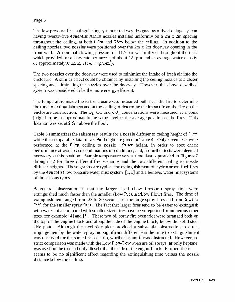
The low pressure fire extinguishing system tested was designed as a fixed deluge system having twenty-five AquaMist AM10 nozzles installed uniformly on a 2m x 2m spacing throughout the ceiling, at both 0.2m and 0.9m below the ceiling. In addition to the ceiling nozzles, two nozzles were positioned over the 2m x 2m doorway opening in the front wall. A nominal flowing pressure of 11.7 bar was utilized throughout the tests which provided for a flow rate per nozzle of about 12 lpm and an average water density of approximately 3mm/min (i.e. 3 1pm/m2).
The two nozzles over the doorway were used to minimize the intake of fresh air into the enclosure. A similar effect could be obtained by installing the ceiling nozzles at a closer spacing and eliminating the nozzles over the doorway. However, the above described system was considered to be the more energy efficient.
The temperature inside the test enclosure was measured both near the fire to determine the time to extinguishment and at the ceiling to determine the impact from the fire on the enclosure construction. The 02, CO and C02 concentrations were measured at a point judged to be at approximately the same level as the average position of the fires. This location was set at 2.5m above the floor.
Table 3 summarizes the salient test results for a nozzle diffuser to ceiling height of 0.2m while the comparable data for a 0.9m height are given in Table 4. Only seven tests were performed at the 0.9m ceiling to nozzle difhser height, in order to spot check performance at worst case combinations of conditions; and, no further tests were deemed necessary at this position. Sample temperature versus time data is provided in Figures 7 through 12 for three different fire scenarios and the two different ceiling to nozzle diffuser heights. These graphs are typical for extinguishment of hydrocarbon fuel fires by the AquaMist low pressure water mist system [ 1, 21 and, I believe, water mist systems of the various types.
A general observation is that the larger sized (Low Pressure) spray fires were extinguished much faster than the smaller (Low PressureLow Flow) fires. The time of extinguishment ranged from 23 to 80 seconds for the large spray fires and from 5:24 to 7:30 for the smaller spray fKes. The fact that larger fires tend to be easier to extinguish with water mist compared with smaller sized fires have been reported for numerous other tests, for example [4] and [5]. These two oil spray fire scenarios were arranged both on the top of the engine block and along the side of the engine block, below the solid steel side plate. Although the steel side plate provided a substantial obstruction to direct impingement by the water spray, no significant difference in the time to extinguishment was observed for the same fire scenario, whether or not it was obstructed. However, no strict comparison was made with the Low FlowLow Pressure oil sprays, as only heptane was used on the top and only diesel oil at the side of the engine block. Further, there seems to be no significant effect regarding the extinguishing time versus the nozzle distance below the ceiling.
~o~wc.95 429

Page 7
Another visual observation was related to the change in temperature and, therefore, pressure inside the enclosure during the fire extinguishment process. This was observed on the flow in and out of the doorway opening, especially during the tests where the time to extinguishment was longer. The flow periodically changed from an outflow of smoke and water vapor over the complete cross section of the opening to an inflow of air at the bottom half of the opening. The outward flow of smoke corresponded to an over pressure within the compartment and vice versa. Rapid extinguishment resulted in a major inward draft with the water spray from the nozzles over the doorway being drawn into the enclosure over a meter, at floor level, followed by a return of the smoke and water spray to an almost neutral state.
The minimum O2 concentration at the measurement point ranged from approximately 15% to 19.3%, the CO concentration from below 0.01% to approximately 0.26% and the C02 concentration from approximately 1.4% to 3.4%. The large fire scenarios show a very rapid initial reduction in the O2 concentration. This was due to the activation of the nozzles, which drove the smoke trapped at the ceiling level down, towards the measurement point. The reduction in the average O2 concentration for the enclosure, to the 15 to 19% range, clearly made it easier for the water mist system to extinguish the various fires. However, the levels were well above the 9% value for Class A fires and the 13% value for Class B fires which are generally associated with extinguishment by oxygen starvation.
Regarding the ceiling temperatures, the fire scenarios on the top of the engine mock-up caused the highest temperatures. The fire scenarios with a Low Pressure oil spray angled 45" up rapidly resulted in ceiling gas temperatures in excess of 900OC; however, the fires in the two tests were extinguished in an average of about one minute. When the time to extinguishment was prolonged, for example in the Low PressureLow Flow and pool/flowing fire scenarios, the temperatures at the ceiling were controlled to moderate levels.
In tests 1.14 and 1.18, a constant leakage flow of heptane was arranged on top of the engine block. The fuel was allowed to form a 3 m2 pool on the top, flow down one side of the engine block and into a 4m2 tray underneath the floor plates. In both cases, the system extinguished the fire in the top tray first. The leakage flow was not turned off, after extinguishment of the top tray fire, which resulted in the fuel forming a pool fire underneath that burned up the side of the engine block. This pool fire was extinguished, in both cases, after approximately four minutes.
430 HOTWC.95
---I.- ___- -
Page 8
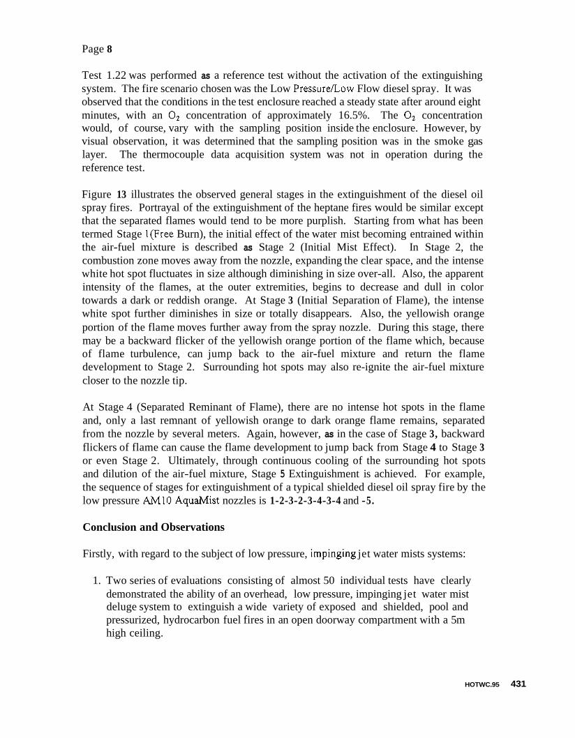
Test 1.22 was performed as a reference test without the activation of the extinguishing system. The fire scenario chosen was the Low PressureLow Flow diesel spray. It was observed that the conditions in the test enclosure reached a steady state after around eight minutes, with an O2 concentration of approximately 16.5%. The O2 concentration would, of course, vary with the sampling position inside the enclosure. However, by visual observation, it was determined that the sampling position was in the smoke gas layer. The thermocouple data acquisition system was not in operation during the reference test.
Figure 13 illustrates the observed general stages in the extinguishment of the diesel oil spray fires. Portrayal of the extinguishment of the heptane fires would be similar except that the separated flames would tend to be more purplish. Starting from what has been termed Stage l(Free Burn), the initial effect of the water mist becoming entrained within the air-fuel mixture is described as Stage 2 (Initial Mist Effect). In Stage 2, the combustion zone moves away from the nozzle, expanding the clear space, and the intense white hot spot fluctuates in size although diminishing in size over-all. Also, the apparent intensity of the flames, at the outer extremities, begins to decrease and dull in color towards a dark or reddish orange. At Stage 3 (Initial Separation of Flame), the intense white spot further diminishes in size or totally disappears. Also, the yellowish orange portion of the flame moves further away from the spray nozzle. During this stage, there may be a backward flicker of the yellowish orange portion of the flame which, because of flame turbulence, can jump back to the air-fuel mixture and return the flame development to Stage 2. Surrounding hot spots may also re-ignite the air-fuel mixture closer to the nozzle tip.
At Stage 4 (Separated Reminant of Flame), there are no intense hot spots in the flame and, only a last remnant of yellowish orange to dark orange flame remains, separated from the nozzle by several meters. Again, however, as in the case of Stage 3, backward flickers of flame can cause the flame development to jump back from Stage 4 to Stage 3 or even Stage 2. Ultimately, through continuous cooling of the surrounding hot spots and dilution of the air-fuel mixture, Stage 5 Extinguishment is achieved. For example, the sequence of stages for extinguishment of a typical shielded diesel oil spray fire by the low pressure AM10 Aquah4ist nozzles is 1-2-3-2-3-4-3-4 and -5.
Conclusion and Observations
Firstly, with regard to the subject of low pressure, impinging jet water mists systems:
1. Two series of evaluations consisting of almost 50 individual tests have clearly demonstrated the ability of an overhead, low pressure, impinging jet water mist deluge system to extinguish a wide variety of exposed and shielded, pool and pressurized, hydrocarbon fuel fires in an open doorway compartment with a 5m high ceiling.
HOTWC.95 431

Page 9
2. At this point in technology development, comparative tests in large compartments indicate that internal scroll water mist systems operating at pressures greater than 100 bar will provide somewhat faster extinguishment times than the low pressure, impinging jet nozzles. However, the low pressure approach offers a viable alternative when considering simplicity, reliability, filtration requirements, installed cost and maintenance.
With regard to the general subject of water mist systems, the following viewpoints are offered:
A. The effectiveness of gases such as Halon is not affected by shielding or obstructions whereas, they are clearly a consideration in the case of water mist.
B. The design of a gas distribution system primarily involves compartment volume and delivery rate considerations while the design of a water mist system involves nozzle spacing, application density, compartment height as well as concealment considera- tions.
C. Gases such as Halon simply become non-effective with ventilation while a definable degree of ventilation can be tolerated with water mist.
For these reasons, I believe that the implications of the term “Halon Options” or “Alternatives to Halon” are much more preferable with regard to describing deluge type water mist systems than the phrase “Halon Alternative”.
Lastly, with regard to the general fire extinguishment attributes of water mist systems, I would like to offer the following observations:
a. It will be an extremely difficult task to reliably predict the complexities of ex- tinguishment of Class B fires by water mist systems through the use of first principles.
Factors such as the interactive effects between nozzles operating in an array, the effects of combustion products being drawn down from the ceiling, shielding, mist momentum and trajectory as well as localized cooling and oxygen depletion phenomena will make this a very formidable task.
b. Low flash point pool fires, such as those typified by heptane, are primarily extinguished by driving the mist tothe burning surface and separating the flammable vapors from it through expansion of the resulting water vapor. Once separated, the resulting residual vapors are dispersed and diluted to the point of extinguishment.
432 HOTWC.95

Page 10
Simply surrounding a horizontally and vertically shielded low flash point liquid pool fire, in a ventilated enclosure, with low momentum droplets, will not result in extinguishment by localized cooling or oxygen depletion. The flame front simply overpowers the mist and essentially drives it away. Because of this, it will be highly improbable that any type of ceiling mounted, overhead water mist system will be able to extinguish the 0.5m2 pan fires positioned underneath the engine block, in the IMO machinery space test procedures.
c. Trying to extinguish a flammable liquid fire with water mist by overpowering it from all directions is ineffective.
Light areas need to be intentionally left within the nozzle spray patterns which will allow the flames to escape from the burning area. In the case of the low pressure AquaMist system, this is accomplished by leaving light density areas between the conical spray patterns while the areas between the individual sprayers of multi- orifice nozzles accomplishes the same effect.
HOTWC.95 433

REFERENCES
1. Pepi, Jerome S., Fire Test Status Report on the Evaluation of the AquaMist Fixed Water M s t Deluge System in Ventilated Marine Machinery Spaces, SFPE Technical Symposium on Halon Alternatives, Knoxville, TN, 28 June 1994.
2. Arvidson, Magnus, “Machinery Space Fire Tests for Grinnell Fire Protection Using AquaMst AMI0 Nozzles”, SP Test Report R30494b, February 1995.
3. SFPE, Fire Protection Handbook, National Fire Protection Association, Quincy, MA, USA, 17th edition.
4. Wighus, Ragnar, et al, Full Scale Water Mist Experiments, International Conference on Water Mist Fire Suppression Systems, Boras Sweden, November 4-5, 1993.
5 . Mawhinney, Jack R., Design of Water Mist Fire Suppression Systems for Shipboard use, International Conference on Water Mist Fire Suppression Systems, Boras, Sweden, November 4-5, 1993.
6 . Standard for the Installation of Water Mist Fire Suppression Systems, NFPA 750, National Fire Protection Association, Batterymarch Park, Quincy, MA USA, (Draft, to be published in 1996).
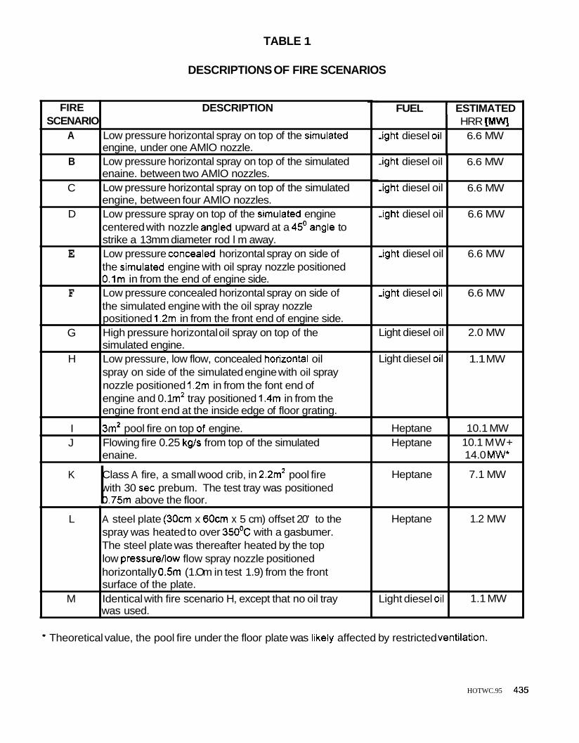
TABLE 1
DESCRIPTIONS OF FIRE SCENARIOS
FIRE SCENARIO
A
B
DESCRIPTION
Low pressure horizontal spray on top of the simulated engine, under one AMlO nozzle. Low pressure horizontal spray on top of the simulated enaine. between two AMlO nozzles.
,ight diesel oil
Class A fire, a small wood crib, in 2.2m2 pool fire with 30 sec prebum. The test tray was positioned I 0.75m above the floor.
K
HRR [MWJ 6.6 MW
-ight diesel oil
,ight diesel oil
Jght diesel oil
Jght diesel oil
igh t diesel oil
Light diesel oil
Light diesel oil
FUEL I ESTIMATED
6.6 MW
6.6 MW
6.6 MW
6.6 MW
6.6 MW
2.0 MW
1.1 MW
C
D
E
F
G
H
I J
Low pressure horizontal spray on top of the simulated engine, between four AMlO nozzles. Low pressure spray on top of the simulated engine centered with nozzle angled upward at a 45' angle to strike a 13mm diameter rod l m away. Low pressure concealed horizontal spray on side of the simulated engine with oil spray nozzle positioned O.lm in from the end of engine side. Low pressure concealed horizontal spray on side of the simulated engine with the oil spray nozzle positioned 1.2m in from the front end of engine side. High pressure horizontal oil spray on top of the simulated engine. Low pressure, low flow, concealed horizontal oil spray on side of the simulated engine with oil spray nozzle positioned 1.2m in from the font end of engine and 0.1 m2 tray positioned 1.4m in from the engine front end at the inside edge of floor grating.
3m2 pool fire on top of engine. Flowing fire 0.25 kg/s from top of the simulated enaine.
Heptane Heptane
10.1 MW
14.0 M W 10.1 MW+
Heptane
* Theoretical value, the pool fire under the floor plate was likely affected by restricted ventilation.
7.1 MW
HOTWC.95 435
L
M
A steel plate (30cm x 60cm x 5 cm) offset 20' to the spray was heated to over 350'C with a gasbumer. The steel plate was thereafter heated by the top low pressure/low flow spray nozzle positioned horizontally 0.5m (1 .Om in test 1.9) from the front surface of the plate. Identical with fire scenario H, except that no oil tray was used.
Heptane
Light diesel oil
1.2 MW
1.1 MW

c
r9
0 Y N
0 v) +I 0 N
0
-
0
I:
436 HOTWC.95

W p? 3 v) s Y
0 o r : r
Y) l Y )
N
.
H
B E 1 rn
B m .- .+: E u) 0
u) Q
._ 3
a e B E e B E
3 E 0) c 3 O
r
a
B 0 - n
3 c u) Q U 'S E 2 B
1 4 3 c
Q
E
c 0 Q
u) P,
E
1 8
f E
B B
e
c m
- 8
H
u)
0) - a € c E 0)
n b Y
E
B 3 r 0
._ s U m .+: C
._
.- 8 m
i= n 00 Y
0 z
HOTWC.95 437

k .E = E
B P a i
i r
4 4
u) s
888 8 eDQ)
9i c 0
- I
- I
P
438 HOlWC.95

m
"l 0 I FFUSER-,
I
- 3 1 mm-
I
~ m m 4 3 m m
\TI I
Patented and Patents Pending
Figure 1 Illustration Of
AguaMist AM1 0 Nozzle
r
HOlWC.95 439
I ’*
i
Figure 2 Number Of Droplets Versus Drop Diameter
For AM10 Nozzle At 12 Bar One Meter Below Diffuser
Figure 3 Cumlative Volume Versus Drop Diameter
For AM10 Nozzle At 12 Bar One Meter Below Diffuser

A c
8 (B 8 8
Floor platr: syste m
tB
18
(B
Ceiling TC
Gas sampling point (2.5 rn above floor)
I 8 (B 8
I I B
2 r n
I T I O m
2 r n
2 r n I 2) El I / Doorwav nozzles
TOR view
0.2 m and 0.9 m respectively
Ceiling nozzles (25)/
Doorway nozzles (2)
Section view A-A
Figure 4 Illustration Of Enclosure
And Nozzle Locations
I m * I 3,
HOTWC.95 441

442 HOTWC.95
1 rn 2.0 r rn
L
Solid steel date
I 3.5 rn
Solid floor plates 4 x 6 m outside I dimensions 7
Unhidden spray
t Steel plate Concealed m a y r - 1.i m I I I
2.5 m
5 mm steel plate Baffles surrounding
\4 rn2 tray \2 mm steel piate (bottom)
Figure 5 Plan And End Elevation Views
Of Engine Mock-up
.

/ \
/ \ / \
/ I I' \ I \
\ \
\ I
I
Detail of notch for flowing fire scenario
Figure 6 Side Elevation View Of Engine Mock-up And
Detail Of Top Tray Notch
I
HOTWC.95 443

8 BAR DIESEL OIL SPRAY FIRE ANGLED 45' UPWARD ON TOP OF ENGINE MOCK-UP
1- INITIATION OF WATER FLOW
* O o o ~ 800
Figure 7 Test 1 .ll Ceiling Gas Temperature
Over Center Of Diesel Engine Mock-up (Ceiling To AM10 Nozzle Diffuser Height Of 0.2 m)
8 BAR DIESEL OIL SPRAY FIRE ANGLED 45' UPWARD ON TOP OF ENGINE MOCK-UP
I ~ ' " ' " ' ~ ! ' ' ' ! ~ ' " ~ ' ' ~ I I INITIATION OF WATER FLOW
444 HOTWC.95
0 2 4 6 8 I O Time [minutes]
Figure 8 Test 1.16 Ceiling Gas Temperature
Over Center Of Diesel Engine Mock-up (Ceiling To AM10 Nozzle Diffuser Height Of 0.9 m)
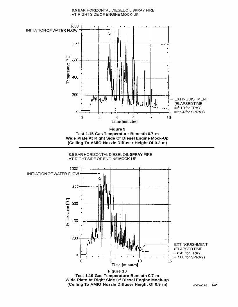
8.5 BAR HORIZONTAL DIESEL OIL SPRAY FIRE AT RIGHT SIDE OF ENGINE MOCK-UP
INITIATION OF WAT
- EXTINGUISHMENT (ELAPSED TIME = 5:l 9 for TRAY
- = 524 for SPRAY) 0 2 4 s 10
Time [minutes]
Figure 9 Test 1.15 Gas Temperature Beneath 0.7 m
Wide Plate At Right Side Of Diesel Engine Mock-Up (Ceiling To AMlO Nozzle Diffuser Height Of 0.2 m)
8.5 BAR HORIZONTAL DIESEL OIL SPRAY FIRE AT RIGHT SIDE OF ENGINE MOCK-UP
lo00 INITIATION OF WATER FLOW
800
s e600 2 a u
EXTINGUISHMENT (ELAPSED TIME
- = 6:45 for TRAY 1 = 7:OO for SPRAY) u ~ , , , ' i , , , ' , , , l 1
0 5 10 15 Ttme [minutes]
Figure 10 Test 1.19 Gas Temperature Beneath 0.7 m
Wide Plate At Right Side Of Diesel Engine Mock-up (Ceiling To AMlO Nozzle Diffuser Height Of 0.9 m) HOTWC.95 445

FLOWING HEPTANE FIRE
1000
INITIATION OF WATER FLOW
uc e600 2
E 3
u Y
E- 400 G
200
0 0 2 4 6 8 10
Time [minutes]
Figure 11 Test 1.14 Ceiling Gas Temperature
Over Center Of Diesel Engine Mock-up (Ceiling To AM10 Nozzle Diffuser Height Of 0.2 m)
INITIATION OF
446 HOTWC.95
WATER
FLOWING HEPTANE FIRE
I I J EXTINGUISHMENT OF TRAY FIRE (ELAPSED TIME = 050) FLOW
800 I V
--
- %oo
-
2
2
3400 (ELAPSED TIME = 4:12)
3
0)
Y
-- EXTINGUISHMENT OF BILGE
G
200
O ' , # I I I I I I l l I l l , 1 1 1
2 I
0 2 4 6 8 10 Time [minutes]
Figure 12 Test 1.18 Ceiling Gas Temperature
Over Center Of Diesel Engine Mock-up (Ceiling To AM10 Nozzle Diffuser Height Of 0.9 m)
FIRE

STAGE I : FREE BURN
I ‘CLEAR (AIR - FUEL MIXTURE)
I STAGE 2 : INITIAL MIST EFFECT
~
STAGE 3 : INITIAL SEPARATION OF FLAME
STAGE 4 : SEPARATED REMINANT OFFLAME
YELLOWISH ORANGE
ORANGE
I STAGE 5 : EXTINGUISHMENT
Figure 13 General Stages In The
Extinguishment Of A Diesel Oil Spray Fire By The AM10 AquaMist Nozzles HOTWC.95 447