Embed Size (px)
Citation preview

J. Manuf. Mater. Process. 2020, 4, 19; doi:10.3390/jmmp4010019 www.mdpi.com/journal/jmmp
Article
Performance Comparison of Subtractive and Additive Machine Tools for Meso‐Micro Machining
(Peter) H.‐T. Liu 1,* and Neil Gershenfeld 2
1 OMAX Corporation, 21409 72nd Avenue South, Kent, WA 98032, USA 2 The MIT Center for Bits and Atoms, Room E15‐401, 20 Ames Street, Cambridge, MA 02139, USA;
* Correspondence: [email protected]; Tel.: +1‐(253)‐872‐2300
Received: 1 January 2020; Accepted: 25 February 2020; Published: 3 March 2020
Abstract: Several series of experiments were conducted to compare the performance of selected sets
of subtractive and additive machine tools for meso‐micro machining. Under the MicroCutting
Project, meso‐micro machining of a reference part was conducted to compare the performance of
several machine tools. A prototype flexure of the microspline of an asteroid gripper under
development at NASA/JPL was selected as the reference part for the project. Several academic,
research institutes, and industrial firms were among the collaborators participating in the project.
Both subtractive and additive machine tools were used, including abrasive waterjets, CNC milling,
lasers, 3D printing, and laser powder bed fusion. Materials included aluminum, stainless steel, and
nonmetal resins. Each collaborator produced the reference part in its facility using materials most
suitable for their tools. The finished parts were inspected qualitatively and quantitatively at OMAX
Corporation. The performance of the participating machine tools was then compared based on the
results of the inspection. Test results show that the two top performers for this test part are the CNC
precision milling and micro abrasive waterjet. For machining a single flexure, the CNC precision
milling had a slight edge over the micro abrasive waterjet machining in terms of part accuracy and
edge quality. The advantages disappear or the trend even reverses when stack machining with taper
compensation is adopted for the micro abrasive waterjet.
Keywords: meso‐micro machining; micro abrasive‐waterjet technology; stacking cutting; micro
milling; taper compensation; flexure; subtractive machining; additive machining; micrograph
1. Introduction
With the development and commercialization of micro‐abrasive waterjet (AWJ) technology,
supported under an NSF SBIR Phase II/IIB grant, OMAX added a MicroMAX® to its product lines of
JetMachining® Centers. In collaboration with MIT Center for Bits and Atom (CBA) and Department
of Mechanical Engineering, the performance of abrasive waterjet (AWJ) was compared with those of
lasers, wire EDM, and CNC milling [1–4]. Reference parts including miniature butterflies, tweezers,
and nonlinear load cells were selected to cut with these tools. Based on their interesting performance
comparison, a MicroCutting Project was initiated with the objective to broaden the performance
comparison by including several selected sets of modern additive and subtractive machine tools.
2. Technical Approach and Equipment
2.1. Technical Approach
A collection of machine tools available at OMAX, CBA, and other facilities were selected for the
project. One of the early tasks was to define a reference part that was suitable to be machined and/or
fabricated with all the selected machine tools. A decision was made to use one the flexures

J. Manuf. Mater. Process. 2020, 4, 19 2 of 26
investigated at NASA/JPL as a key component of prototype microsplines for asteroid grippers
developed under the Asteroid Redirect Mission [5,6]. As shown in Figure 1, the flexure consists of 11
full‐length and 2 half‐length spring‐like elements. The length and width of the flexure elements were
36.3 mm and 0.5 mm, respectively. The separation between each element was 0.76 mm. The aspect
ratio (length/width) was therefore 72.6. The widths of the element and gap between them are 0.51
mm and 0.76 mm, respectively. The aspect ratios of the length‐to‐width and length‐to‐thickness were
71.5 and 47.7. The above are the dimensions of the full‐scale flexure. Small‐scale flexures with 0.5, 0.4,
and 0.33 were also machined using several tools. The flexure is extremely delicate and flexible. It took
only very weak side force exerted onto the flexure element during machining to deflect them
permanently. During the course of machining, strengthening tabs were used to support the delicate
elements (Figure 1a). Figure 1b shows the tool path with several color coded curves: green – traverse
without cutting, magenta – lead in and out, and blue – cut at quality five level. The tool path shown
in Figure 1b included two steps: (1) machine the flexure with the tabs in place and (2) remove the
tabs. Figure 1c shows the final part with the tabs removed.
The flexure, machined or fabricated from materials that were most suitable for the individual
tools, were then inspected qualitatively and quantitatively to compare the performances of these
machine tools.
2.2. Micro Abrasive Waterjet Technology
The AWJ is amenable to micromachining as the diameter of the AWJ can potentially reduce to
micro scales [7]. The μAWJ technology was developed and commercialized under the support of an
SBIR Phase II/IIB grant. Several novel processes were developed and incorporated into the
MicroMAX for meso‐micro machining of 2D and 3D parts. The main focus was to downsize the AWJ
nozzle capable of meso‐micro machining. As such, several challenges were present as the three‐
phase, supersonic slurry flow inside the nozzle transitions from a gravity‐dominated flow to a
microfluidic flow. Novel processes and apparatus were developed to enable μAWJ technology for
industrial applications [4].
At present, the 7/15 nozzle with an orifice and a mixing tube ID of 0.007” (0.18 mm) and 0.015”
(0.38 mm) is the smallest production nozzle whereas the 5/10 nozzle is currently used for special
applications. Garnet with 240 mesh can be readily used with these nozzles. For garnets finer than 240
mesh, a proprietary process was developed to enhance their flowability. Success in developing the
AWJ technology led to the culmination in the release of the MicroMAX as a new product debuted in
2013. It has a position accuracy and repeatability of 15 μm and 5 μm, respectively. A MicroMAX
version II with the incorporation of a Rotary Axis for machining axisymmetric features was released
for production in 2016.
(a) With strengthening tabs (b) Tool path
(c) Finish Flexure
Figure 1. DXF of flexure selected as the reference part for the MicroCutting Project.

J. Manuf. Mater. Process. 2020, 4, 19 3 of 26
2.3. Machine Tools and Participants
The participants in the Microcutting Project included MIT/CBA (www.cba.mit.edu), OMAX
(www.omax.com), Formlabs (www.formlabs.com), Datron (www.datron.com/), (Moog Inc.
(http://www.moog.com/), and BMF Precision Technology Co, Ltd. (http://bmftec.com/). Machine
tools available at the facilities of the participants and used in the project included CBA Digital
Fabrication Facility (http://cba.mit.edu/tools/index.html) Beam Dynamics Model LMC10000 CO2
laser system—1.2 m × 1.2 m cutting area, 30.5 m vertical travel, 500 w (1550 W peak), 25 m overall accuracy, 51 m/min max cutting speed (91 m/min traverse speed) Sodick SL400G Wire EDM—X, Y,
Z Axis travel, 400 × 300 × 250 mm; wire diameter range: 0.051 to 0.30 mm.
Zund G‐3 L‐2500—Repeatability ± 0.03 mm, position accuracy ± 0.1 mm/m, working area 1800
mm × 2500 mm, high speed router 3.6 kW 50,000 rpm.
FabLight 3000 Fiber Laser—3 kW laser, working area of 6.35 m × 1.27 m and tubes of diameter
12.7 mm to 5.1 mm. Capable of cutting steel, stainless steel, spring steel, aluminum, copper, brass,
titanium. Repeatability of 15 m, accuracy of ± 20 m/m.
Oxford Solid State Micromachining Laser—532 nm diode‐pumped solid‐state laser, 150 mm X‐
Y travel, 50 mm Z travel, 1 micron resolution. It has spot size of approximately 20 microns. The laser
outputs approximately 6W of power at 10 kHz and can quickly cut through materials typically up to
0.5 mm thick. Itʹs used for fine cutting, ablation, engraving, and marking
OMAX 5555 JetMachining Center at CBA—X‐Y Travel 1.4 × 1.4 m, Tilt‐A‐Jet, MAXJET 5i Nozzle
(10/21), 7/15 Mini MAXJET 5 Nozzle, Precision Optical Locator, pneumatic drill OMAX Corporation
MicroMAX—A MicroMAX equipped with a Tilt‐A‐Jet (TAJ), a Rotary Axis (RA), and a Precision
Optical Locator (POL) is available at the OMAX facility (https://www.omax.com/omax‐
waterjet/micromax). For meso‐micro machining, the 7/15 and 5/10 nozzles have been used routinely
for cutting demo parts and conducting in‐house R&D. The nozzles were driven by an EnduroMAX
40 hp crankshaft pump (Model 4060V) with pressures up to 410 MPa. For these small nozzles, an
excess flow control valve was installed to drain a part of the water through the high‐pressure pump.
At pressures below about 70 MPa, the Bernoulli vacuum was too weak to entrain all the abrasive into
the mixing chamber. Vacuum Assist accessory was used to remove the excessive abrasive to mitigate
clogging of the nozzle.
AWJ machining was controlled by an IntelliMAX Software Suite featuring an extensive tool set
to streamline production. The Suite is based on a precision cutting model in which each engineering
material is assigned with a machineability index according to its properties derived from the results
of extensive cutting tests. The intuitive Suite that is easy to use consists of a PC‐based CAD‐LAYOUT
and CAM‐MAKE. A set of steel slats spaced 25 mm apart is installed inside each JetMachining Center
to support the workpiece. A 10 cm thick polyurethane honeycomb placed on top of the slats is often
used to provide a firm support to workpieces made from thin materials. Since the AWJ exerts very
low force onto the workpiece, it can be secured by relatively simple fixtures such as carpenter clamps.
A number of options is available to secure the workpiece depending on the setup. For small parts,
thin tabs are incorporated into the tool path to prevent losing it into the tank below. Machining is
carried out by setting a standoff distance of 0.76 mm between the tip of the nozzle to the top surface
of the workpiece. The tool offset is set to on half of the exit diameter of the AWJ. Depending on the
thickness of the workpiece and the required edge quality of cut from Q1 for raw cut to Q5 for
precision cut, the cutting speed is set intelligently by MAKE according to the machineability index.
The cutting speed also varies according to the shape and curvature of the tool path. For example, the
traverse of the nozzle speeds up in straight segments and slows down during corner passing to
maintain the same kerf width.
Formlabs‐Form 2 Printer ‐ Build Volume: 145 × 145 × 175 mm, Layer Thickness: 25, 50, 100
microns, Laser Spot Size: 140 m, Laser Power: 250 mW, Wavelength: 405 nm (violet), automated
resin system, self‐heating resin tank, auto‐generated supports. Machine size: 350 mm (L) ×330 mm
(W) ×520mm (H)
Moog, Inc. —These parts were made from metal powders, an aluminum alloy and stainless steel,
using laser powder bed fusion. The equipment included:

J. Manuf. Mater. Process. 2020, 4, 19 4 of 26
EOS 290 for 17‐4PH stainless steel: laser power—220 watts, volume scan speed—750 mm/s,
volume hatch spacing—0.11 mm, layer thickness—40 m;
SLM 280 for aluminum (twin laser): laser power—350 watts, volume scan speed—1650
mm/s, volume hatch spacing—0.13 mm, layer thickness—30 m.
They were then trimmed to correct thickness with a 0.25‐mm wire EDM (Mistsubishi MV2400S)
for 30 min approximately.
Boston Micro Fabrication (BMF) Material Technology Inc.—Digital Lighting Processing (DLP),
similar to Stereolithography Appearance (SLA), was used to fabricate the flexures
(https://web.archive.org/web/20140221025534/, https://thre3d.com/how‐it‐works/light‐
photopolymerization/digital‐light‐processing‐dlp). It is a 3D printing process working with
photopolymers. In DLP, a 3D model is constructed and ‘sliced’ through software. Once the sliced
images are received by the printer, curable liquid, e.g. monomer or pre‐cured resin, is exposed to a
pattern of UV‐light, in order to selectively solidify a cross‐section of the designed parts. The cured
cross‐section is then lowered below the surface level of the liquid, allowing the liquid to backfill for
curing and bonding of subsequent cross‐sections. The process is repeated until all the slices of the 3D
model and hence the printing parts are completed. The liquid is then drained from the vat, followed
by demolding and post‐curing of the parts. The nanoArch Micro Scale 3D Printing System InP140
(https://bmftec.com/) nanoArch® is the first commercialized high resolution, multimaterial 3D micro‐
fabrication equipment based on PμLSE (Projection Micro Litho Stereo Exposure) technology, which
is designed for scientific R&D of functional composite materials.
Datron‐Neo Milling Machine (https://www.datron‐neo.com/us/datron‐neo‐simple‐
milling/overview/). Masking tapes and super glue were used to secure the workpiece onto the
substrate.
For the full‐scale flexure, the first operation was a 2D contour used to cut the profile of the
internal flexure geometry using a double flute 0.030” (0.76 mm) end mill with ethanol coolant.
Ethyl alcohol, used in minimal quantities, appeared to have no negative effect on the work
holding. The last operation was cutting the perimeter with a 3 mm single flute end mill.
For the half‐scale flexure, the first operation was a 2D contour used to cut the profile of the
internal flexure geometry using a double flute 0.5 mm end mill with ethanol coolant. Ethyl
alcohol, used in minimal quantities, appeared to have no negative effect on the work holding.
Datron tooling was used, which led to slightly undersized internal geometry. The internal
geometry was 0.008” (0.20 mm) instead of the 0.010” (0.25 mm) as modeled due to the larger tool
size being used. The last toolpath was cutting the part out with the 3 mm single flute end mill.
3. Results
For this project, one of the flexures as a key component of a prototype microspline of an asteroid
gripping device under development at NASA/JPL for the Asteroid Redirect Mission [5,6]. The
delicate geometry of the selected flexure, as shown in Figure 1, presented considerable challenge to
most machine tools. There is an option to (1) machine or fabricate the flexure with the strengthening
tabs attached (Figure 1a) and then remove the tabs to finish the part or (2) machine the flexure without
the tabs (Figure 1b).
3.1. Waterjet Cutting
The prototype flexure made of 6061 T6 aluminum using the MicroMAX was originally cut to
demonstrate its performance versus that of the wire EDM. The EDM process conducted at JPL was
carried out in three passes in order to minimize the damage resulted from the induced heat‐affected
zone (HAZ). The comparison showed that the cost ratio for machining the part was 14:1 in favor of
the waterjet, leading to a 93% cost reduction [3].
Figure 2a shows the micrograph of the aluminum flexure (0.81 mm THK) cut on the MicroMAX
using the 7/15 nozzle with the Barton 240 or 220UT mesh garnet with a mean particle size of 60 m.
The pump pressure was 380 MPa and the abrasive mass flow rate was 73 g/min. The cutting time was
2.3 min. The geometry of the flexure element including the horizontal and semi‐circle segments were

J. Manuf. Mater. Process. 2020, 4, 19 5 of 26
inspected under the microscope. From the micrographs, the following features of the flexure are
inspected:
a. Edge quality
‐ Smoothness and the presence of chipping
‐ Edge taper
b. Variation in the element width (over or under cutting)
c. Variation in the gap between horizontal segments
d. Straightness (local bending) of horizontal segments
e. Parallelism of the horizontal segments
Figure 2b shows the superimposition of the tool path onto the flexure element. The overall match
between the tool path and the flexure element is excellent, indicating that there is no distortion of the
flexure element in terms of bending and/or rotating in the X‐Y plane.
Magnified views of the two small areas in the middle span and the right end loops of Figure 2a,
were selected to compare in detail the flexure element and the tool path, as shown in Figures 2c and
2d. The areas were chosen because they were farthest away from the two anchoring points and least
supported. The selection was made to show the worst mismatches in those two segments of the entire
element. Yet, the match shown in Figure 2c is excellent. A very slight mismatch is observed in Figure
2d. The maximum mismatch was measured to be about 0.1 mm, part of which is attributed to the
error in overlaying of the tool path onto the micrograph. Figures 2c and 2d show nearly no macro
distortion induced by the waterjet cutting process, clearly demonstrating the advantages of cold
cutting and low‐side‐force exertion. In fact, previous investigation verified that waterjet, as opposed
to wire EDM, preserved the structural and chemical integrity of parent materials [8].
(a) Micrograph (b) Tool path versus micrograph
(c) Zoomed (mid) (d) Zoomed (end)
Figure 2. Aluminum flexure ‐ MicroMAX.
The same flexure was then cut from a stainless‐steel sheet (0.76 mm THK). The same cutting
parameters for cutting the aluminum flexure were used. The cutting time increased to 3.4 min. Figure
3 illustrates the micrograph of the stainless‐steel flexure. The flexure element displays no heat‐ and/or
mechanically‐induced distortion. Using the 7/15 nozzle, a 2/3‐size but not a half‐size flexure was
successfully cut as the kerf width of the 7/15 nozzle is larger than the gap between elements of the
half‐size flexure.

J. Manuf. Mater. Process. 2020, 4, 19 6 of 26
Figure 3. Stainless steel flexure ‐ MicroMAX.
Full‐size flexures were cut on CBA’s OMAX 5555. The same setup for the 7/15 nozzle was used.
Figure 4 shows micrographs of two flexures cut on aluminum (0.81 mm THK) and stainless steel (0.64
mm THK). In Figures 4a and 4b the overall geometry shows no noticeable distortion of the flexure
element. Minor mismatches between the tool path and the flexure element are however observed in
the zoomed‐in micrographs of the aluminum flexure as shown in Figures 4c and 4d that correspond
to the mid‐span and right end segments of the second and third loops from the top. In the mid‐span
(Figure 4c), an undercut section about 9 mm long was observed on one of the horizontal segments
(third row down. The maximum undercut is about 0.15 mm. Since this is the only occurrence
throughout the entire flexure element, it is most likely just an outliner. The maximum mismatch at
the two ends is about 0.1 mm. As shown in Figure 4d, the Y‐positions of the first loop are slightly
below its designed positions marked by the tool path. In other words, this corresponds to the small
rotational (clockwise) distortion about the axis of the X‐Y plane. Note that no such rotational
distortion was observed on the part cut with the MicroMAX (Figure 2d). Comparison of Figure 4c
and 4d with Figures 2c and 2d indicated that the cutting accuracy is slightly better for the MicroMAX
than for the OMAX 5555. This is expected as MicroMAX was specifically designed and constructed
for meso‐micro machining.
(a) Aluminum (b) Stainless steel
(c) Zoomed (mid of a.) (d) Zoomed (end of a.)
Figure 4. Metal flexures – 5555 JMC (CBA).
3.2. Zund
Aluminum flexure (2024 0.51 mm THK) was machined on the Zund G‐3 L‐2500. Machining was
carried out using a 0.76 mm diameter end mill with amorphous diamond coating (Harvey Tool 72030‐
C4). The end mill was driven by a 50 krpm spindle. A faced aluminum sheet was used to provide a
level and rigid support to the stock. PSA tapes burnished with a small stainless‐steel rod were applied

J. Manuf. Mater. Process. 2020, 4, 19 7 of 26
to both surfaces of the support and the underside of the stock. The tapes were then bonded with CA
glue.
The cutting time was 2.5 minutes that is comparable to the waterjet on the aluminum sheet 1.6
times thicker. Figure 5 shows the micrographs of the flexure (a), superposition of tool path flexure
element (b), and the corresponding zoomed sections (c and d). Figure 5b shows that the overall
geometry of the flexure matches well with the tool path. Magnified views of two segments of the
mid‐span and left end of the fourth and fifth loops from the top are shown in Figures 5c and 5d
(flipped horizontally). They reveal that there are minor mismatches between the flexure element and
the tool path. The maximum mismatch is about 0.1 mm. Figure 5d shows that the mismatches were
also attributed to rotational distortion.
By comparing the magnified micrographs of flexures machined with the two waterjets and
Zund, the match between the tool path and the flexure element appeared to be slightly better for the
one cut with the MicroMAX than the one cut with the Zund whereas the match between the tool path
and one cut with the OMAX 5555 ranked third. For the flexure machined on the MicroMAX, the
mismatch was mostly attributed to undercutting at the end loops. All the horizontal segments of the
flexure element show no observable rotational distortion about the axis perpendicular to the X‐Y
plane. For the flexure machined on the Zund, the mismatches were attributed to the rotational
distortion of the several segments of the element about the axis perpendicular to the X‐Y plane. Note
that there were differences in the fixturing setup. During waterjetting, tabs were used to strengthen
the flexure element. They were then cut away after machining of the flexure element were completed.
On the other hand, the Zund machined the flexure without tabs. The support was provided by the
PSA tapes bonded together with the CA glue.
A 0.5 scale flexure (2024 aluminum 0.51 mm THK) was machined on the Zund by using a 0.38
mm diameter end mill with amorphous diamond coating. It took about 8 minutes to cut that part.
Figure 6a shows the half‐size flexure. There was only a negligible distortion of the flexure element.
One of the most important attribution to the success in cutting the delicate flexure was the use of the
diamond coated end mill. According to Toress et al. [9], the fine grain nanocrystalline diamond
(NCD) coating, with average grain size 30–300 nm, reduced the thrust and main cutting forces to less
than 50%, compared with uncoated tools, when machining 6061 T6 aluminum. One of the failure
modes was delamination of the coating. After delamination, the tool looks similar to an uncoated tool
with worn and/or broken tool corners and adhered workpiece material. End mills coated with the
NCD experienced delamination about one half of those coated with the fine‐gained diamond (FGD)
counterpart. At present, the materials most suitable for the Zund are limited to relatively soft
materials (At present, aluminum is the only metal recommended by Zund
(http://fab.cba.mit.edu/content/tools/zund/manual.pdf).
(a) Aluminum (b) Tool path overlaid onto core of flexure
(c) Zoomed (mid) (d) Zoomed (end)
Figure 5. Aluminum flexure – Zund (CBA).
J. Manuf. Mater. Process. 2020, 4, 19 8 of 26
0.5 scale aluminum flexures were also machined on the MicroMAX. A beta 5/10 nozzle with IDs
of a diamond orifice and a mixing tube, 0.13 and 0.25 mm, was used to machine the flexures. Several
cutting parameters were set to pump pressure, 345 MPa, garnet 320 mesh at a flow rate 45 mg/min.
For the powdery 320 mesh garnet, however, it did not flow well under gravity feed. A proprietary
process and a novel feeding apparatus were developed to enhance flowability of the fine powdery
garnet under gravity feed (patented). Figure 6b shows the waterjet‐cut half‐size flexure on 6061 T6
aluminum. Its element shows no observable distortion.
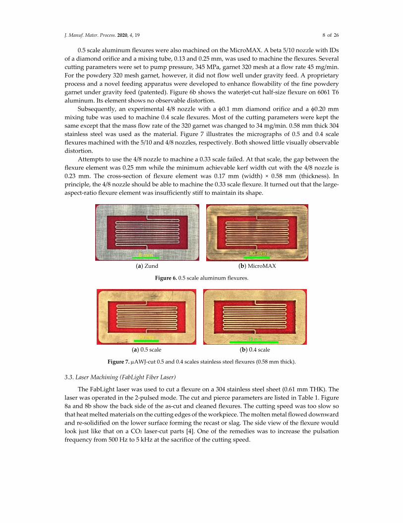
Subsequently, an experimental 4/8 nozzle with a 0.1 mm diamond orifice and a 0.20 mm
mixing tube was used to machine 0.4 scale flexures. Most of the cutting parameters were kept the
same except that the mass flow rate of the 320 garnet was changed to 34 mg/min. 0.58 mm thick 304
stainless steel was used as the material. Figure 7 illustrates the micrographs of 0.5 and 0.4 scale
flexures machined with the 5/10 and 4/8 nozzles, respectively. Both showed little visually observable
distortion.
Attempts to use the 4/8 nozzle to machine a 0.33 scale failed. At that scale, the gap between the
flexure element was 0.25 mm while the minimum achievable kerf width cut with the 4/8 nozzle is
0.23 mm. The cross‐section of flexure element was 0.17 mm (width) × 0.58 mm (thickness). In
principle, the 4/8 nozzle should be able to machine the 0.33 scale flexure. It turned out that the large‐
aspect‐ratio flexure element was insufficiently stiff to maintain its shape.
(a) Zund (b) MicroMAX
Figure 6. 0.5 scale aluminum flexures.
(a) 0.5 scale (b) 0.4 scale
Figure 7. AWJ‐cut 0.5 and 0.4 scales stainless steel flexures (0.58 mm thick).
3.3. Laser Machining (FabLight Fiber Laser)
The FabLight laser was used to cut a flexure on a 304 stainless steel sheet (0.61 mm THK). The
laser was operated in the 2‐pulsed mode. The cut and pierce parameters are listed in Table 1. Figure
8a and 8b show the back side of the as‐cut and cleaned flexures. The cutting speed was too slow so
that heat melted materials on the cutting edges of the workpiece. The molten metal flowed downward
and re‐solidified on the lower surface forming the recast or slag. The side view of the flexure would
look just like that on a CO2 laser‐cut parts [4]. One of the remedies was to increase the pulsation
frequency from 500 Hz to 5 kHz at the sacrifice of the cutting speed.

J. Manuf. Mater. Process. 2020, 4, 19 9 of 26
Table 1. Cut and pierce parameters of FabLight laser.
Cut
Parameters
Speed
mm/s
Power
%
Gas Pressure
MPa
Height
mm
Frequency
Hz
Focal Offset
mm
2.5 15 0.41 0.76 500 −0.76
Pierce
Parameters
Pulses Power
% Pressure MPa
Height
mm
Frequency
Hz
Duration
ms
1 10 0.41 1.52 500 12
(a) As‐cut (b) Cleaned
Figure 8. Stainless steel flexure – FabLight Fiber Laser (CBA).
3.4. Laser Powder Bed Fusion‐LPBF (Moog)
At Moog, flexures made from metal powders, AlSi10MG and 17‐4 stainless steel, were fabricated
using laser powder bed fusion (LPBF). Table 2 lists the process parameters. The flexures were then
cut to desire thickness using wire EDM. Flexures with and without the tabs were built. Figure 9 shows
the two 0.51 mm thick aluminum flexures (9a with tabs and 9b without tab) and a 0.64 mm thick
stainless steel (9c. without tab). The surface pattern observed in the figure was left behind by the wire
EDM trimming. From the high‐resolution micrographs, the width of the elements is consistent. There
is however minor distortion of the elements in terms of bending are observed, resulting in small
variations in the gap width between the elements. The degree of distortion is less for the ones with
tabs. Without the tabs, the distortion is less for the 17‐4 build than for the aluminum counterpart. The
density of metals produced via LPBF is typically 99.7% that of (fully dense) wrought material [10].
The reduction in density is due to various forms of material defect, which are typically small i.e. less
than 0.10 mm. These defects in concert with a rough as built surface finish can result in reduced
fatigue performance when compared with smooth surfaced wrought material. For example, the S‐N
(stress versus number of cycles to failure) curves for LPBF‐built AlSi10MG using the ALB1 process
show that the average fatigue life of specimens printed at 0, 30, 60, and 90 degrees is about 65% of
that of the aluminum wrought [11]. The fatigue life of the SLM (selective laser melting)‐built steel 630
is about 57% that of its wrought [9]. It has been demonstrated that the fatigue life of SLM AlSi10Mg
parts can been extended to about 8% by machining and heat treatment [12]. Tests will be needed to
determine whether 3D printing would be suitable to fabricate flexure for the intended application. It
should be pointed out that the fatigue lives of AWJ‐cut aircraft aluminum and titanium were able to
extend considerably through dry‐grit blasting on the part edges [13,14].
3.5. 3D Printing (NanoArch Micro Scale – BMF InP140/InS140)
Flexures were printed at BMF Material Technology, Inc. in Shenzhen City, Guangdong Province,
China. Flexures were printed using two materials, GR and HTL, that were acrylic based
photosensitive resin developed by BMF. Refer to its material properties in Table 3
(https://bmf3d.com/materials/). Two GR flexures (0.51 mm and 1.02 mm THK) are shown in Figures
10a and 10b. The surfaces of the flexures were quite smooth and flat. Both showed noticeable
distortion along the direction of the Y‐axis on the X‐Y plane. A portion of the element segments were
bent slightly as indicated by the nonuniform gap width between several straight sections of the

J. Manuf. Mater. Process. 2020, 4, 19 10 of 26
element. The distortion is more severe on the thick flexure than on the thin one. Figure 10c shows a
third flexure built from the HTL material in black color. Distortion of the flexure element was also
observed.
Table 2. Metal flexures – laser powder bed fusion.
Metal Flexures Aluminum Alloy Stainless Steel
Powder Materials Used AlSi10Mg 17‐4 PH Stainless
Steel
Equipment‐Manufacturers EOS 290 SLM 280, twin laser
Laser Power (W) 350 220
Volume Scan Speed (mm/s) 1650 750
Volume Hatch Spacing (mm) 0.13 0.11
Layer Thickness (�m) 30 40
Part Thickness (mm)§ 0.51 0.64
Wire EDM‐Mistsubishi MV2400S Wire Dia. 0.25 mm, ~30 min per part
Build Time (hrs) 5 5
Heat Treatment¥ (°C/hrs) 300/3 1150/1.5
Tools for Removal of Support
Structure
Pliers, custom fixture and pneumatic
cutoff wheel § Used wire EDM to trim to desired part thickness. ¥ For stress release only.
(a) AlSi10Ng with tab (0.51 mm THK) (b) AlSi10Ng without tab (0.51 mm THK)
(c) 17‐4 Stainless steel (0.64 mm THK)
Figure 9. Metal flexures – LBPF.
Table 3. Material properties of GR and HTL.
Resin GR (Hard) HTL
Tensile Strength 85 MPa 79.3 MPa
Elasticity Modulus 3.8 GPa 4.2 GPa
Elongation at Break 3% 2.23%
Bending Strength 97.4 MPa 120.6 MPa
Flexure Modulus 3.2 GPa 3.96 GPa
Impact Strength 47.5 J/m 30 J/m
Distortion Temperature 45 MPa 102 °C 140.7 ℃

J. Manuf. Mater. Process. 2020, 4, 19 11 of 26
(a) 0.51 mm THK GR (b) 1.02 mm THK GR
(c) 0.51 mm THK HTL
Figure 10. 3D‐printed flexures (BMF).
3.6. 3D Printing (Formlabs – Form 2)
Stereolithography, an additive manufacturing process that polymerizes a liquid resin with light,
was used at Formlabs to print two different sets of flexure with different supporting structures [15].
A Model Form 2 printer, a galvanometer system to steer a laser on a cure plane for this purpose, was
used in this case. A model is sliced into layers as thin as 0.025 �m and created layer‐by‐layer on this
cure plane (https://formlabs.com/blog/ultimate‐guide‐to‐stereolithography‐sla‐3d‐printing/).
Wherever the laser hits the resin, the material hardens into the final part. An inverse
stereolithography process, parts are formed ʺupside downʺ, and are drawn up from a tank full of
rigid resin that was reinforced with glass to offer very high stiffness and polished finish [16].
Figure 11 illustrates two flexures built with the Form 2. The horizontal and radial elements of
both flexures display considerable distortion. According to Formlabs, the peel and squish forces of
the print process were most likely responsible for the distortions. After each layer, the part separates
(ʺpeelsʺ) from the tank. This motion is a combination of the tank moving laterally and the Z‐axis
moving upwards. After separation, the part then returns to its original position, though one‐layer‐
thickness higher. For small fragile parts with long thin features, this separation and return can
generate forces that cause the part to return slightly off of position. Since there are lots of thin features
next to each other, over time this displacement added up enough to cause them to get close enough
such that the liquid resin around them caused them to stick together through viscous forces such as
surface tension, enough to hold them in place.
3.7. Micromachining (Datron)
High‐speed CNC milling was used to machine two flexures (full and 1/2 scales) at Datron. They
were cut on a double flute end mill using ethanol coolant on a NEO CNC Machine equipped with
the Autodesk Fusion 360 software. The material was 2024 aluminum 0.51 mm thick. The aluminum
sheet was secured with masking tape and super glue. The cutting parameters were given in Table 4.
Figure 12 shows the two flexures. There is no apparent distortion on the horizontal and radial
segments of the full‐scale flexure element. However, there is observable distortion on the top three
horizontal segments with non‐uniform gap spacing. It was noted that workpiece holding issues
prevented optimization of speeds and feeds. A very shallow depth of cut and slow feed rate was
required to prevent tool breakage. An uneven application of the superglue underneath the masking
tape could cause tools to break. This allowed for slight movement of the workpiece during

J. Manuf. Mater. Process. 2020, 4, 19 12 of 26
machining. It was also very difficult and time consuming to remove the tape and super glue on the
flexure without damaging the delicate part.
(a) Flexure 1 – top view (b) Flexure 2 – top view
(c) Flexure 1 – side view (d) Flexure 2 – angle view
Figure 11. Flexures built with rigid resin – 3D printing (Formlabs).
Table 4. Cutting parameters for micromachining with Datron Neo CNC Machine.
Scale
(%) Article No.
Ø End Mill
(mm)
RPM
(x1000)
Feed XY
(mm/min)
Feed Z
(mm/min)
D.O.C.¥
(mm)
W.O.C.§
(mm) Cycle Time
100 N/A 0.76 38 1016 254 0.127 0.76 6 min 1 s
50 0068005KK 38 12 5.00 0.003 0.019
0.48 38 305 127 0.076 0.48 16 min 12 s
¥ Depth of cut; § Width of cu.
(a) Full size (b) 0.5 scale
Figure 12. Aluminum flexures – Neo at Datron.
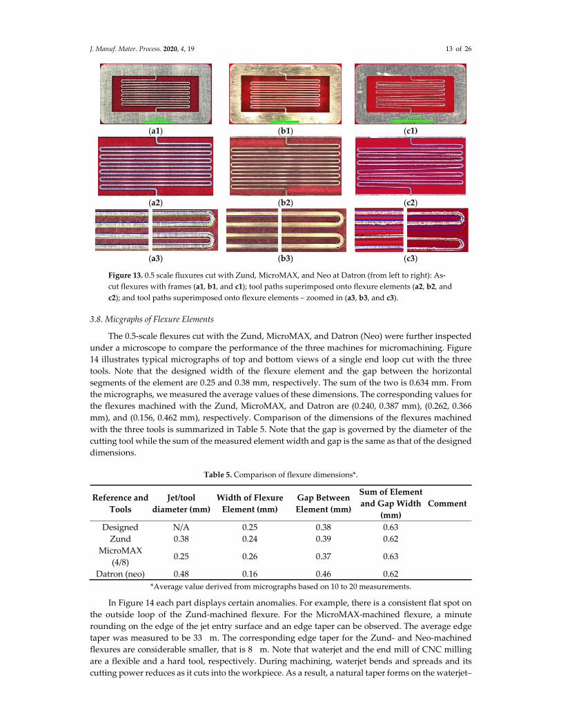
Micrographs of the half‐scale flexures machined with the Zund, MicroMAX, and Neo (at Datron)
are replotted side‐by‐side in Figure 13. Figures 13a1, b1, and c1, 13a2, b2, and c2, and 13a3, b3, and
c3 show the as‐cut full flexures, cores of the flexure elements overlaid with the tool paths, and the
magnified views of the mid‐span and two end loops of the flexures, respectively. Visual comparison
of the micrograph of the waterjet‐cut flexure and the tool path shows no degradation (column b)
resulted from the downsizing. The maximum deviation is still about 0.1 mm. Since there is a slight
edge rounding on the jet entry surface of the flexure, the micrograph shown in column b corresponds
to the jet‐exit surface of the flexure. In the presence of the edge taper, the width of the flexure element
is slightly but consistently wider than the tool path in the presence of the edge taper. For the Zund‐
cut counterpart, however, the downsizing has led to certain degradation in the match between the
flexure and the tool path. Figure 13a3 displays noticeable rotational distortion. The maximum
mismatch was measured to be 0.27 mm, nearly three times that for the full‐scale flexure. Considerable
rotational distortion is observed for the Neo‐cut half‐scaled flexure, as shown in Figure 13c3. The
maximum mismatched was measured to be 0.66 mm.
J. Manuf. Mater. Process. 2020, 4, 19 13 of 26
(a1) (b1) (c1)
(a2) (b2) (c2)
(a3) (b3) (c3)
Figure 13. 0.5 scale fluxures cut with Zund, MicroMAX, and Neo at Datron (from left to right): As‐
cut flexures with frames (a1, b1, and c1); tool paths superimposed onto flexure elements (a2, b2, and
c2); and tool paths superimposed onto flexure elements – zoomed in (a3, b3, and c3).
3.8. Micgraphs of Flexure Elements
The 0.5‐scale flexures cut with the Zund, MicroMAX, and Datron (Neo) were further inspected
under a microscope to compare the performance of the three machines for micromachining. Figure
14 illustrates typical micrographs of top and bottom views of a single end loop cut with the three
tools. Note that the designed width of the flexure element and the gap between the horizontal
segments of the element are 0.25 and 0.38 mm, respectively. The sum of the two is 0.634 mm. From
the micrographs, we measured the average values of these dimensions. The corresponding values for
the flexures machined with the Zund, MicroMAX, and Datron are (0.240, 0.387 mm), (0.262, 0.366
mm), and (0.156, 0.462 mm), respectively. Comparison of the dimensions of the flexures machined
with the three tools is summarized in Table 5. Note that the gap is governed by the diameter of the
cutting tool while the sum of the measured element width and gap is the same as that of the designed
dimensions.
Table 5. Comparison of flexure dimensions*.
Reference and
Tools
Jet/tool
diameter (mm)
Width of Flexure
Element (mm)
Gap Between
Element (mm)
Sum of Element
and Gap Width
(mm)
Comment
Designed N/A 0.25 0.38 0.63
Zund 0.38 0.24 0.39 0.62
MicroMAX
(4/8) 0.25 0.26 0.37 0.63
Datron (neo) 0.48 0.16 0.46 0.62
*Average value derived from micrographs based on 10 to 20 measurements.
In Figure 14 each part displays certain anomalies. For example, there is a consistent flat spot on
the outside loop of the Zund‐machined flexure. For the MicroMAX‐machined flexure, a minute
rounding on the edge of the jet entry surface and an edge taper can be observed. The average edge
taper was measured to be 33 �m. The corresponding edge taper for the Zund‐ and Neo‐machined
flexures are considerable smaller, that is 8 �m. Note that waterjet and the end mill of CNC milling
are a flexible and a hard tool, respectively. During machining, waterjet bends and spreads and its
cutting power reduces as it cuts into the workpiece. As a result, a natural taper forms on the waterjet–

J. Manuf. Mater. Process. 2020, 4, 19 14 of 26
cut edges. On the other hand, the end milling is in direct contact with the cut edge of the workpiece.
The minute edge taper is likely caused by the deflection of the miniature end mill. The JetMachining
Center is equipped with a 5‐axis accessory, Tilt‐A‐Jet (TAJ), capable of compensating edge taper
(https://www.omax.com/accessories/tilt‐a‐jet). The TAJ is however not effective in machining thin
materials; it will be applied to stack cutting in Section 3.9.
Comparison of these values with the designed dimensions indicates that the flexures machined
with the Zund and the MicroMAX match well with the designed dimensions. The large deviations of
the element width and the gap on the flexure cut with the neo at Datron is attributed to the large
diameter of the end mill (0.48 mm). Figure 14f shows that the Neo did not cut through the materials
at several spots (below the green dashed line). The poor performance of the Neo is partly attributed
to the imperfect fixturing to secure the workpiece, according to Datron. As a result, the workpiece
might have been moved during machining. Using better tape and more even application of super
glue, similar to the process used on the setup of the Zund, would likely allow an increase to depth of
cut and feed rate, reducing the cycle and handling times of this operation.
3.9. Measured Width of Flexure Elements
The widths of the flexure elements were measured from the micrographs to compare the cutting
accuracy of the AWJ on the MicroMAX and the CNC milling on the Zund. Figure 15 shows the
micrographs of the top and bottom views of flexure elements machined on the MicroMAX and Zund,
respectively. Comparing Figures 15a and 15b shows that the bottom elements are slightly wider than
their top counterparts. This is the result of the presence of edge taper as the TAJ was deactivated for
cutting thin materials. There are two options to reduce or minimize the magnitude of the edge taper.
One remedy is to reduce the cutting speed and the other is to conduct stack cutting. The OMAX
MAKE software incorporates an optimal stack height calculator.
(a) Zund – top surface (b) Zund – bottom surface (flipped)
(c) MicroMAX – jet entry surface (d) MicroMAX – jet exit surface (flipped)

J. Manuf. Mater. Process. 2020, 4, 19 15 of 26
(e) Datron (Neo) – top surface (f) Datron (Neo) – bottom surface (flipped)
Figure 14. Visual comparison of micrographs of top and bottom surfaces of half‐scale flexures cut
with Zund, MicroMAX, and Neo at Datron.
The average widths of the top and bottom flexure elements were measured from the
micrographs and are presented in Figure 16. Also shown in the figure are their trendlines and the
designed width of the flexure elements. The maximum deviations between the trendlines and the
designed width are 0.004 mm and −0.0003 mm for the AWJ‐ and Zund‐cut flexures. The measured
width of the flexure machined with both tools displays a consistent pattern with the even segments
wider than the odd counterparts. The difference in the width between the odd and even elements is
considerably larger for the AWJ‐cut flexure than for the Zund‐cut one. Careful examination of the
tool path shown in Figure 1b indicates that, for waterjet machining, the nature of the machining
differs for the odd and even segments of the flexure elements. Specifically, the odd and even elements
were cut in the constrained and unconstrained modes, respectively.
(a) Top ‐ 7/15 nozzle, MicroMAX
(b) Bottom – 7/15 nozzle, MicroMAX
(c) Top – Zund with 0.76 mm end mill
(d) Bottom – Zund with 0.76 mm end mill
Figure 15. Width of flexure elements measured from micrographs.
Unconstrained or constrained cuttings referred to the conditions that the edges of the adjacent
elements had already or yet to be cut. Note that the tool offset for the 7/15 nozzle is one half of the

J. Manuf. Mater. Process. 2020, 4, 19 16 of 26
mixing tube diameter, or 0.38 mm whereas the gap between elements are 0.76 mm. While cutting the
odd segments, the AWJ is constrained by the materials on both edges (C‐C). The AWJ cut nearly
straight downward. On the other hand, for the even segments with the edges of the adjacent segments
already cut, the AWJ is unconstrained on both edges (U‐U). This is referred to as the constrained‐
constrained and unconstrained‐unconstrained (C‐C/U‐U) cutting mode. Under the U‐U cutting
mode, the AWJ tends to be deflected slightly toward the adjacent segments where the material
beyond those edges have been removed. As such, the even segments are slightly wider than their
odd counterparts. Refer to Figure 17 for a graphical interpretation of the two modes of cutting.
Figure 16. Average element widths of full‐scale flexure (C‐C and U‐U) machining mode).
Figure 17. Tool path for the C‐C and U‐U cutting mode.
The remedy to mitigate the difference in the element width is to revise the tool path such that
the machining must be carried out consistently in the unconstrained‐unconstrained (U‐U) or
alternating constrained‐unconstrained (C‐U) modes for all the elements. For the unconstrained mode,
a slotting in the middle of the gap between elements, as illustrated in Figure 18, is added to the tool
path (magenta dotted lines). As such, all the edges are carried out in the unconstrained mode. The
second remedy is to split the tool path of the flexure element into two sub‐segments at the left turn‐
around points as shown in Figure 19. Cutting are conducted by cutting all the top edges in the
constrained mode followed by cutting the bottom edges in the unconstrained mode. As such, the
edges will be cut in the C‐U mode.

J. Manuf. Mater. Process. 2020, 4, 19 17 of 26
Figure 18. Tool path for U‐U cutting mode.
Cutting tests using both modes were conducted on 0.51‐mm thick aluminum. The difference in
the width of the odd and even flexure elements reduced significantly and were about the same as
that cut with the Zund, as shown in Figure 20. However, the pre‐slitting along the middle of the gaps
significantly weakened the stiffness of the workpiece, particularly toward the mid‐span. During the
passage of the AWJ, the force exerted onto the workpiece tended to push the flexure elements
sideway and downward, particularly at mid‐span where the support was the minimum. As a result,
the element width became nonuniform along the length of the flexure element. In particular, the
width increased from one end, reached the maximum at the mid‐span, and then reduced toward the
opposite end, as shown in Figure 21. The same trend with less severity was observed for the C‐U
cutting mode.
Figure 19. Tooth path for C‐U cutting mode.

J. Manuf. Mater. Process. 2020, 4, 19 18 of 26
Figure 20. Comparison of average element widths of flexures cut with AWJ (U‐U mode) and Zund.
Figure 21. Nonuniform element width resulted from the C‐U cutting mode.
The above anomalies of the observed nonuniformity of the element width along its major axis is
attributed to the weak stiffness of the flexure element due to its peculiar geometry.
A set of flexure elements with large aspect ratios of length/width and length‐/thickness.
The stiffness of the serpentine flexure supported only on two end points connected to its frame
is the weakest at the mid‐span.
For cutting very thin materials, the cutting speed is too fast for the TAJ to respond with taper
compensation. Therefore, the TAJ is usually deactivated resulting in measurable edge taper. Figure
22 shows the measured element width at the mid‐span of a 0.51 mm thick stainless‐steel flexure under
the C‐C/U‐U cutting mode. In addition to the nonuniform element width of the even and odd flexure
segments, the presence of the edge taper resulted in a difference of about 0.1 mm between the element
widths measured on the top and bottom surfaces.
Subsequently, we decided on adopting the AWJ stack cutting process as the final remedy to
minimize the nonuniformity of the width of the even and odd flexure elements and the edge taper.
The stack was formed by using 3M double‐adhesive tapes with a thickness of about 60 m. A 10 mm
thick aramid honeycomb with fiberglass faceplates was used to support the metal stack for further
enhancing the stiffness. The cutting model is equipped with a stack calculator to estimate the
optimum number of layers based on the cutting parameters. The optimum number of sheets is
defined as the total stack height at which the average cutting time per sheet has reached the
minimum. Figure 23 illustrates the results of stack calculation for two aluminum (0.51 and 0.64 mm
thick) and one stainless steel (0.51 mm thick), respectively. The estimated numbers of layers for the
three metals cut at the quality level of five are 13, 10, and 7, respectively. The cutting times for single
sheets reduce from 3.90 to 0.90, 4.13 to 1.12, and 4.95 to 1.80 min, respectively. The reductions in the
cutting time are 4.4, 3.7, and 2.8 times for the three metals.

J. Manuf. Mater. Process. 2020, 4, 19 19 of 26
Figure 24 show the side view of a stack of flexure consisting of one 0.41 mm thick aluminum
sheet and five 0.51 mm thick stainless‐steel sheet. The top aluminum sheet served as the sacrificial
cover where the edge rounding, and frosting took place. Several iterations of cutting with the TAJ
activated to minimize the edge tape were conducted. Figure 25 illustrates the element widths of one
of the interior flexures (#5) of the stack shown in Figure 24. The significant reduction in the edge taper
of the AWJ‐cut flexure was evident when compared the data shown in Figures 24 and 25. Although
the edge taper was still slightly higher than that of the Zund‐cut counterpart it can further reduce
with additional iterations. Most important, the stack cutting eliminated the difference in the width of
the even and odd elements, even below the level achievable with the Zund.
Figure 22. Edge taper resulted from deactivation of the TAJ.
Figure 23. Typical optimum stack heights for two metals.
Figure 24. AWJ‐cut stack of stainless‐steel flexure supported by aramid honeycomb.

J. Manuf. Mater. Process. 2020, 4, 19 20 of 26
With the increase in the stiffness of the stack together with the support of the honeycomb, the
sideway and downward displacements of the flexure element in response to the AWJ loading also
reduced considerably. As a result, the nonuniformity of element width reduced accordingly, as
shown in Figure 26. In fact, comparing Figures 26 and 27 shows that the total variation in the element
width was less for the AWJ‐cut flexure than the Zund‐cut counterpart.
Yet another advantage of stack cutting is to use the top sheet as the sacrificial cover to reduce
frosting on the top surface and the burr on the bottom edge of the interior sheets.
3.10. Further Downsizing of AWJ Nozzle
As discussed in Section 3.2, machining a 0.33 scale flexure was unsuccessful using the 4/8 AWJ
nozzle. One of the reasons was that the kerf width of the nozzle was nearly the same as the width of
the gap of the flexure. During machining the AWJ traversed twice (back and forth) through the gap.
In the presence of edge rounding on entry side, the strength or stiffness of high‐aspect‐ratio flexure
element might be weakened to the degree that it could no longer maintain its shape without
distortion. Further downsizing the AWJ nozzle might be needed to machine the 0.33 scale flexure
successfully.
Figure 25. Comparison of element width of flexures cut with Zund and AWJ under stack cutting at
mid‐span.
Figure 26. Element width measured at mid‐span and one end of flexure cut with AWJ under stack
cutting.

J. Manuf. Mater. Process. 2020, 4, 19 21 of 26
Figure 27. Element width measured at mid‐span and right end of single‐sheet flexure cut with
Zund.
Attempts were made to assemble a 2/6 AWJ nozzle to machine the flexure. The length of the
0.15 mm mixing tube was reduced to 12.7 mm. Specially processed 320 mesh garnet with a flow rate
of 30 mg/min was used. The vacuum assist option was activated to boost the low Venturi vacuum
induced by the small waterjet. Figure 28 shows the comparison of three stainless steel flexures, with
scale of 0.5 (a1–a3), 0.4 (b1–b3), and 0.33 (c1–c2), machined on the MicroMAX with the 5/10, 4/8, and
2/6 nozzle, respectively. As discussed in Sections 3.2 (Figures 2 and 5) and 3.7 (Figure 13a, b), the
matches between the tool paths and the full‐and 0.5‐scale parts were slightly better for the AWJ–cut
flexures than for the Zund‐cut counterparts. Figure 28c3 shows that the overall match between the
0.33‐scale flexure and the tool path displayed a slight localized degradation when compared with the
matches with its larger counterparts.
(a1) (b1) (c1)
(a2) (b2) (c2)
(a3) (b3) (c3)
Figure 28. Downsized stainless steel flexures cut with AWJ nozzlles on MicroMAX: flexure with
frames (a1, b1, and c1); tool paths superimposed onto flexure elements (a2, b2, and c2); and tool
paths superimposed onto flexure elements ‐ zoomed in (a3, b3, and c3).

J. Manuf. Mater. Process. 2020, 4, 19 22 of 26
Considerable R&D is being conducted to continue downsizing AWJ nozzles toward
micromachining. The material independent waterjet is capable of machining a wide range of part size
and thickness [1,2]. One of the main concerns is the lack of proper fixturing devices to hold extremely
thin stocks for micromachining. The success in applying AWJ stack cutting to stiffen the workpiece
while enhancing the cutting efficiency has eased the above concern and paved the way for precision
AWJ micromachining of very thin stocks provided further development of AWJ technology would
meet the stringent requirements. A wide range of materials from metal, nonmetal, to anything in
between can be used to form the stack [2].
4. Discussion and Summary
Cutting tests were conducted to investigate the performance comparison of AWJ, lasers, wire
EDM and CNC milling. These tests were investigated through the collaboration of MIT and OMAX
Corporation [4]. The results demonstrated that AWJ using the MicroMAX had the best overall
performance for this test part, with the fastest cutting speed without inducing heat damage to the
parts. The CO2 laser performed the worst causing significant heat damage (i.e., the presence of the
HAZ) in terms of discoloring, warping, and the presence of excess slag. The solid‐state laser pulsed
at 50 kHz with a spot size of around 50 m and the wire EDM with a 0.15 mm wire were able to cut
the parts at significantly slower speed to minimize the heat damage. The cutting speeds were one to
two orders of magnitude slower than that of the MicroMAX. The cutting accuracy of the solid‐state
laser and the wire EDM are however higher than that of the AWJ that had jet diameters of 0.25 and
0.3 mm for the 5/10 and 7/15 nozzles, respectively.
Under the MicroCutting Project, one of the flexures used as the prototype microsplines for the
NASA asteroid gripper was selected as the reference part for all the machine tools investigated. It
must be clarified that such a selection may not necessarily take advantage of the best features of some
of the machine tools. Specifically, the rating of the performance of individual tools was based
narrowly on the inspection of the as machined/built flexures. In other words, the machine tool with
a poor rating in this report does not represent its overall performance for other machining
applications.
Micrographs or photographs of most finished flexures machined with individual tools were
taken for inspection. The graphs were inspected and compared to determine the performance of
individual tools for machining and building of the flexures. The performance was rated based on
several criteria such as the cutting accuracy and speed, degree of part deformation (mechanical and
thermally induced), edge quality, setup time and effort, and others. One of the inspection methods
used frequently was to superimpose the part tool path onto the graph of the flexures as the means to
determine whether there was any mismatch of the two. A mismatch could be caused by 3D part
distortion induced by the cutting tools, inaccurate machining and building, and other factors.
Another inspection method was to measure various dimensions of the flexure such as the width and
the length of the flexure element and the spacing between elements.
3D printing using nonmetals, such as the GR and HTL from BMF and polymer with solid filler
from Formlabs, although precisely fabricated, do not have the strength and stiffness to maintain the
shape of the flexure without distortion in terms of warping, bending, and deflection. Furthermore,
the printing processes usually took hours to complete. AlSi10Mg and 17‐4PH stainless steel flexures
built with LPBF using metal powders and finished the flexures with wire EDM by Moog Inc. appear
to maintain their shape well. They also took several hours to build. Due to the presence of defects
and voids in LPBF‐built materials as compared with the wrought and a relatively rough surface of
the finish parts, their fatigue performance is likely to be negatively impacted. The performance of the
LPBF‐built parts is expected to improve progressively as the process continues to refine.
Thermally based manufacturing processes such as lasers and wire EDM can potentially induce
heat damage resulting from the induction of the HAZ. The remedy is to reduce the cutting power by
pulsing the lasers at high rates or cutting the part with EDM at multiple passes, at the expense of the
cutting time [4].

J. Manuf. Mater. Process. 2020, 4, 19 23 of 26
The test results show that the width of the flexure element is sensitive the mode of cutting for
waterjet. The original tool path consisted “constrained” and “unconstrained” cutting modes for the
odd and even flexure segments, respectively. As a result, the width of the odd segments is slightly
but consistently narrower than that of their even counterpart. One of the remedies was successfully
implemented by modifying the tool path such that the two edges of each element were cut under the
constrained (C) and unconstrained (U) modes, respectively. The large‐aspect ratios of the flexure
element in both length‐to‐width and length‐to‐thickness had very low stiffness. The flexure elements
were displaced sideway and downward in response to the forced exerted by the AWJ. The stiffness
was the weakest at the mid‐span and increases toward the two ends. Test results showed that the
element was wider at the mid‐span than at the two ends, indicating that the material removal was
inversely proportional to the amplitude of the displacement.
Subsequently, AWJ stack cutting was applied to improve the performance of the AWJ. A stack
of several pieces of aluminum and/or stainless steel was assembled by using a 3M double‐sided
adhesive tape. The total thickness of the stack was about 4 mm that was thinner than the optimum
thickness estimated by the optimum stack height calculator resided in MAKE. Test results
demonstrated that AWJ stack cutting has achieved the following improvements:
1. Stacking increases the stiffness of the workpiece and minimizes the lateral and downward
displacement in response to the force exerted by the AWJ. The variation in the flexure width
along the its axis has reduced to the level comparable or better than that of the Zund under single
sheet cutting;
2. Stacking increases the overall thickness of the workpiece enabling the activation of the TAJ for
taper compensation. As such, the edge taper of the flexure reduces significantly and is
comparable to that achievable with the Zund under single sheet cutting;
3. There is considerable potential for further downsizing AWJ technology toward
micromachining of most materials including nanomaterials [2,4,5,17–20]. One of the challenges
is the proper fixturing of extremely thin and delicate materials to facilitate micromachining.
Stack cutting together with honeycomb support has paved the groundwork for AWJ machining
of such materials.
In conclusion, several sets of subtractive and additive machine tools were applied to fabricate a
reference part, a prototype flexure developed at NASA/JPL as components of microsplines on
asteroid grippers for the Asteroid Redirection Mission. Aluminum and stainless‐steel flexures with
scales from full, 0.5, 0.4, to 0.33, were fabricated. Only the AWJ using experimental micro nozzles was
able to fabricate flexures with 0.5 scale and smaller. The performances of the selected tools were
evaluated qualitatively and quantitatively, as summarized in Table A1 in the Appendix. It should be
pointed out that these tools may not be optimized for fabricating the reference part. Based on the test
results, the performances of the AWJ on the MicroMAX platform and the CNC micro milling
conducted on the Zund G‐3 L2500 stood out among all the tools investigated in the MicroCutting
Project. For machining a single piece of flexure, the Zund performed slightly better than the
MicroMAX in terms of part accuracy (element width and the uniformity along its axis) and edge
quality (roughness and taper). When stacking together with taper compensation using the TAJ was
adopted for the AWJ, the above advantages disappeared or the trend even reversed. The combined
stack machining and taper compensation not only improved the part accuracy and edge quality but
also enhanced the productivity of the AWJ. Comparing to single‐sheet machining, optimum
stacking reduced the cutting times to about 4 and 3 folds for aluminum and stainless‐steel sheets,
respectively. As AWJ is further downsized toward micromachining of very thin and delicate
materials, stack machining would an enabling process for fixturing such materials. On the other hand,
stack machining would not be an option for most CNC micromachining as the miniature spindles
and end mills would not be able to handle the increased load thickness of the stack.
Author Contributions: Conceptualization, H.T.L. and N.G.; methodology, H.T.L.; validation, H.T.L.; formal
analysis, H.T.L.; investigation, H.T.L.; resources, N.G.; data curation, H.T.L.; writing—original draft preparation,
H.T.L.; writing—review and editing, N.G.; visualization, H.T.L.; supervision, N.G.; project administration, N.G.;
funding acquisition, N.G. All authors have read and agreed to the published version of the manuscript.

J. Manuf. Mater. Process. 2020, 4, 19 24 of 26
Funding: This research was funded partially by an OMAX IR&D project, an NSF SBIR Phase II grant number
1058278.
Acknowledgments: This work was supported by an independent research and development (IR&D) fund from
OMAX Corporation. The research and development of the micro abrasive waterjet technology was supported
by NSF SBIR Phase 1 and 2 Grants (No. 0944239 and 1058278). Any opinions, findings, and conclusions or
recommendations expressed in this material are those of the authors and do not necessarily reflect the views of
the NSF. Special thanks are to the participating technical personnel at CBA and industrial laboratories and
manufacturers including Formlabs, Datron Moog Inc., and BMF Precision Technology Co, Ltd for
machining/building the reference parts made from various materials and providing them for the evaluation and
comparison of their performances. The authors would also like to thank Dr. Axel Henning for reviewing the
paper.
Conflicts of Interest: The authors declare no conflict of interest.
Appendix
Table 1. Performance comparison – machining single‐sheet flexures under the MicroCutting Project.
Machine Tools [Nozzle
Combination]
Material/THK (mm)
Jet Diameter, Spot Size or Layer
Thickness/Particle Sizes
Position Accuracy/ resolution
Setup Time (min)
Cut/Feed
Speed (m/min)
krpm Cutting Time (min)
Damage (Mech/ Heat)
Comments
MicroMAX [5/10]1 Al/0.64 0.3 mm/30 m ±12 m 10 1.01 N/A 2.22 No Presence of
slight edge rounding and
taper – materials were too thin for TAJ to remove edge
taper effectively
MicroMAX [5/10]1 SS/0.51 0.3 mm/30 m ±12m 10 0.51 N/A 2.82 No
MicroMAX [5/10]3 SS/0.51 0.3 mm/30 m ±12 m 10 0.51 N/A 2.53 No
MicroMAX [7/15] Al/0.64 0.4 mm/60 m ±12 m 10 1.88 N/A 2.54 No
MicroMAX [7/15] SS/0.75 0.4 mm/60 m ±12 m 10 0.72 N/A 3.64 No
5555 [7/15] Al/0.80 0.4 mm/60 m ±76 m 10 1.88 N/A 2.54 No Slight edge rounding and taper – TAJ was
ineffective 5555 [7/15] SS/0.61 0.4 mm/60 m ±76 m 10 0.72 N/A 2.54 No
Zund Al/0.51 0.38 mm ±0.1 mm/m 15 0.07 50 ≤ 82 No Workpiece
must be secured firmly to mitigate movement
during milling
Zund Al/0.51 0.76 mm ±0.1 mm/m 15 0.43 50 2.54 No
Oxford laser SS/0.61 20 m 50 m 20 ‐‐ N/A > 604 Some Pulsed at 5 kHz; scrapped
FabLight fiber laser SS/0.61 25 m ±20 m/m 20 0.15 N/A 54 Yes
Pulsed at 500 Hz; discolored
with slag
Wire EDM SS/0.61 0.15 mm 0.15 mm 25 ‐‐ N/A 604 Some Took too long
to cut. Scrapped
LPBF Moog Inc. Al/0.51 30 m5 30 m long N/A N/A 3004 +
306 N/A Model EOS 2909
LPBF Moog Inc.) 17‐4/0.64 40 m5 40 �m long N/A N/A 3004 +
306 N/A Model SLM 28010
3D printing (DMF) GR/0.51 10 ~ 40 m 25 m Long N/A N/A 354 N/A NanoArch‐
InP140/InS140 3D printing
(DMF) GR/1.02 10 ~ 40 m 25 m Long N/A N/A 704 N/A NanoArch‐InP140/InS140
3D printing (DMF)
HTL/ 0.51 10 ~ 40 m 25 m Long N/A N/A 354 N/A NanoArch‐
InP140/InS140

J. Manuf. Mater. Process. 2020, 4, 19 25 of 26
3D printing (Formlabs)
Rigid resin/ 0.85
140 m 140 m Long N/A N/A 1804 N/A
Form 2‐Stereolithography (angled support)
3D printing (Formlabs)
Rigid resin/ 0.85
140 m 140 m Long N/A N/A 2404 N/A
Form 2‐Stereolithography (vertical support)
Datron ‐ Neo Al/0.51 0.76mm7(flexure)/3mm8 (perimeter) 130 m 30 1.0/1.5 38/32 6.02 No
End mill diameter = gap
width
Datron – Neo Al/0.512
0.48 mm7(flexure)/
3mm8 (perimeter) 130 m 30 0.3/1.5 38/32 16.24 No
Gap too large with end mill diameter > gap
width 1 Nozzle combination [orifice ID/mixing tube ID in thousandth of inch]; 2 Half scale; 3 0.4 scale; 4 Full
scale; 5 Layer Thickness; 6 0.25 Wire EDM finishing time; 7 Double flute carbide end mill; 8 Single
flute carbide end mill; 9 Stress relieved 300C for 3 hrs.; 10 Stress relieved 1150C for 90 min.
References
1. Liu, H.T. “7M”advantage of abrasive waterjet for machining advanced materials. J. Manuf. Mater. Process.
2017, 1, 11.
2. Liu, H.T. Versatility of micro abrasive waterjet technology for machining nanomaterials. In Dekker
Encyclopedia of Nanoscience and Nanotechnology, 3rd ed.; CRC Press, Boca Raton, FL, USA, 2017; pp. 1–18,
doi:10.1081/E‐ENN3‐120054064.
3. Liu, H.T. Precision machining of advanced materials with abrasive waterjets. IOP Conf. Ser. Mater. Sci. Eng.
2017, 164, 012008, doi:10.1088/1757‐899X/164/1/012008.
4. Liu, H.T. Performance comparison of waterjet on meso‐micro machining of waterjet, lasers, wire EDM, and
CNC milling. Int. J. Emerg. Eng. Res. Technol. 2019, 7, 31–46.
5. Wall, M. Inside NASA’s Plan to Catch an Asteroid (Bruce Willis not Required).April, 2013;
https://www.space.com/20612‐nasa‐asteroid‐capture‐mission‐explained.html (accessed on 27 February
2020).
6. Tate, K. How to Catch an Asteroid: NASA Mission Explained (Infographic). April, 2013;
https://www.space.com/20610‐nasa‐asteroid‐capture‐mission‐infographic.html (accessed on 27 February
2020).
7. Miller, D.S. New abrasive waterjet systems to complete with lasers. In Proceedings of the 2005 WJTA
Conference and Exposition, Houston, TX, USA, 21–23 August 2005.
8. Liu, H.T.; Hovanski, Y.; Caldwell, D.D.; Williford, R.E. Low‐cost manufacturing of flow channels with
multi‐nozzle abrasive‐waterjets: A feasibility investigation. In Proceedings of the 19th International
Conference on Water Jetting, Nottingham, UK, 15–17 October 2008.
9. Torres, C.D.; Heaney, P.J.; Sumant, A.V.; Hamilton, M.A.; Carpick, R.W.; Pfefferkorn, F.E. Analyzing the
performance of diamond‐coated micro end mills. Int. J. Mach. Tools Manuf. 2009, 49, 599–619.
10. Stugelmayer, E. Characterization of Process Induced Defects in Laser Powder Bed Fusion Processed
Alsi10mg Alloy. Master’s Thesis, Montana Tech of University of Montana, Butte, MT, USA, 2018.
11. Afkhami, S.; Dabiri, M.; Alavi, S.H.; Björk, T.; Salminen, A. Fatigue characteristics of steels manufactured
by selective laser melting. Int. J. Fatigue 2019, 122, 72–83.
12. Aboulkhair, N.T.; Maskery, I.; Tuck, C.; Ashcroft, I.; Everitt, N.M. Improving the fatigue behavior of a
selectively laser melted aluminum alloy: Influence of heat treatment and surface quality. Mater. Des. 2016,
104, 174–182.
13. Liu, H.T.; Gnäupel‐Herold, T.; Hovanski, Y.; Dahl, M.E. Fatigue performance enhancement of AWJ‐
machined aircraft aluminum with dry‐grit blasting. In Proceedings of the 2009 American Waterjet
Conference, Houston, TX, USA, 18–20 August 2009; p. 15.
14. Liu, H.T.; Hovanski, Y.; Dahl, M.E. Machining of aircraft titanium with abrasive‐waterjets for fatigue
critical applications. ASME J. Press. Vessel Technol. 2012, 134, 011405.
15. D’Urso, P.; Effeney, D.; Earwaker, W.J.; Barker, T.; Redmond, M.; Thompson, R.; Tomlinson, F. Custom
cranioplasty using stereolithography and acrylic. Br. J. Plast. Surg. 2000, 53, 200–204.

J. Manuf. Mater. Process. 2020, 4, 19 26 of 26
16. Ehrlich, D.; Silverman, S.; Aucoin, R.; Burns, M. Laser etching for flip‐chip de‐bug and inverse
stereolithography for MEMS. Solid State Technol. 2001, 44, 145.
17. Liu, H.T.; Cutler, V.; Raghavan, C.; Miles, P.; Webers, N. Advanced abrasive waterjet for precision
multimode machining. In Abrasive Technology—Characteristics and Applications; Rudawska, A., Ed.; Intech
Open Access Publisher: Rijeka, Croatia, 2018; pp. 39–64, ISBN 978‐953‐307‐906‐6.
18. Liu, H.T.; McNiel, D. Versatility of waterjet technology: From macro and micro machining for most
materials. In Proceedings of the 20th International Conference on Water Jetting, Graz, Austria, 20–22
October 2010.
19. Nata Rajan, Y.; Murugesan, P.K.; Mohan, M.; Khan, S.A.N.A. Abrasive water jet machining process: A state
of art of review. J. Manuf. Process. 2020, 49, 271–322.
20. Liu, H.T.; Schubert, E. Micro abrasive‐waterjet technology (Chapter Title). In Micromachining Techniques for
Fabrication of Micro and Nano Structures; Kahrizi, M., Ed.; Intech Open Access Publisher: London, UK, 2012;
pp. 205–234, ISBN 978‐953‐307‐906‐6.
© 2020 by the authors. Licensee MDPI, Basel, Switzerland. This article is an open access
article distributed under the terms and conditions of the Creative Commons
Attribution (CC BY) license (http://creativecommons.org/licenses/by/4.0/).


![Laser Polishing of Additive Manufactured 316L Stainless ...doras.dcu.ie/23212/1/Laser Polishing of Additive Manufactured 316L... · [1–8]. Compared with conventional subtractive](https://img.pdfslide.us/doc/110x75/5f57752d2f5d1e000425cf82/laser-polishing-of-additive-manufactured-316l-stainless-dorasdcuie232121laser.jpg)