Embed Size (px)
Citation preview

1
Performance-based
structural fi re safety design
CFI 00.000 FI/9/2008 Lönnberg Print
Performance-based fi re safety design is an accepted methodology in both Finnish and European building regulations for the verifi cation of structural resistance in fi re conditions. A calculation procedure that takes into account the individual characteristics of the building and passive and active fi re protection methods has been developed in a joint European research project.
A realistic understanding of the behaviour of structures in fi re can be achieved and the overall safety of the building can be verifi ed by using performance-based fi re safety design. Through the more profound understanding of phenomena and a more precise analysis of structures in fi re, an equal to or higher safety level than with prescriptive fi re design can be obtained.
Ruukki on metalliosaaja, johon voit tukeutua alusta loppuun, kun tarvitset metalleihin pohjautuvia materiaaleja, komponentteja, järjestelmiä ja ratkaisukokonaisuuksia. Kehitämme jatkuvasti toimintaamme ja tuotevalikoimaamme vastaamaan tarpeitasi.
67832_RUUKKI_ENG.indd 167832_RUUKKI_ENG.indd 1 19.9.2008 12:33:4619.9.2008 12:33:46

22
Contents
1. Introduction .............................................................................................................................. 3
2. What is performance-based fi re safety design? ...................................................................... 4
2.1. General ........................................................................................................................ 4
2.2. Objectives and Tools ................................................................................................... 5
2.2.1. Safety Level ............................................................................................................. 5
2.2.2. Choice of Design Fire .............................................................................................. 5
2.2.3. Calculation of Fire Development.............................................................................. 5
2.2.4. Behaviour of Structrures in Fire ............................................................................... 6
2.3. The Tasks and Deliverables of Structural Fire Safety Design..................................... 7
2.4. Design Tools ............................................................................................................. 11
3. Acceptability of Performance-Based Fire Design .................................................................. 11
3.1. Building Legislation Requirements ............................................................................ 11
3.2. Required Documentation .......................................................................................... 11
4. Summary and Conclusions ................................................................................................... 11
References ................................................................................................................................. 12
Performance-based structural fi re safety design
67832_RUUKKI_ENG.indd 267832_RUUKKI_ENG.indd 2 19.9.2008 12:33:4719.9.2008 12:33:47

33
1. Introduction
Present day structural fi re resistance regulations are largely based on the so-called standard fi re curve, which has led to very different practices in different European countries. The fi re resistance time for a similar building can vary between 60 minutes in the Netherlands and 120 minutes in Finland, as is the case with a medium-height offi ce building with sprinklers. The effects of sprinklers on structural fi re resistance are not suffi ciently taken into ac-count in general either.
Due to the different uses and other individual characteris-tics of buildings, fi re resistance requirements should be based on factors that actually have an infl uence on the growth and the development of fi res and the safety of per-sons. Such factors include: ● Fire compartment: - type of fi re compartment - size of fi re compartment - geometry of fi re compartment - possible changes in the above during the life cycle of the building● Fire: - different fi re scenarios - probabilities of the occurrence of different fi re scenarios - fi re spread - duration and development of the fi re; also the decrease phase should be taken into account - amount and distribution of fi re load and changes in
these during the life cycle of the building - heat release rate of fi re● Air conditioning and venting● Structural system ● Evacuation possibilities● Safety of fi re fi ghters ● Danger of ignition of the neighbouring buildings ● Active fi re resistance methods
In 1994, a European project called “Natural Fire Safety Concept” (NFSC) [1], [2] was started in order to carry out a systematic examination of the above factors. The project group included 10 research centres from different coun-tries and the work was supervised by a guidance group that consisted of fi re fi ghters, developers of fi re regulations and designers from 11 countries. As a result of the project, a more realistic and reliable approach was developed, tak-ing into account the effects of active fi re protection and the characteristics of real fi res. Natural fi re development can be determined separately for different fi re compartments in a building on the basis of each compartment’s individu-al characteristics. The method can be used for all building materials and all types of buildings.
A method has been developed, where● the individual characteristics of a building, such as the
fi re scenario, fi re load, pyrolysis rate, compartment type and venting, are taken into account.
● the risk of ignition in the building can be taken into ac-count and the infl uence of active fi re protection meth-ods and building type can be evaluated. This risk anal-ysis is based on probabilities that have been evaluated on the basis of real fi re statistics. After the project, the method has been developed further so that the fi re sce-narios are based on a large number of Monte Carlo –simulations that take into account the same factors as above.
● design values for the main parameters (e.g. the fi re load) are evaluated.
● the temperature development is determined as a func-tion of the fi re load. Fire risks and the extinguishing system are taken into account indirectly.
- the temperature development should be taken into account during the complete duration of the fi re, i.e. also during the decrease phase, which is structurally often problematic.
● the behaviour of the structure in fi re is simulated on the basis of temperature development and static loading.
● the fi re resistance time is determined. The fi re resist-ance time can be infi nite, which means that the struc-ture will withstand the loads it is subjected to through-out the fi re.
● the safety of the structure is secured by comparing the calculated fi re resistance time to the required time that depends on evacuation times, the possibilities for re-quired actions by fi re fi ghters and the results of a pos-sible collapse.
This paper presents the basics of natural fi re design, the contents of a structural fi re safety plan and the acceptabil-ity of the methods for the fi re safety design of buildings. In Finland, also the previously published guide book RIL 221-2003 Paloturvallisuussuunnittelu (Fire Safety Design) [3] is available.
It is clear that regardless what fi re design method is cho-sen for a project, it is important to hold a fi re engineering briefi ng among the contractor, the building administration authorities and the designers. This is of primary impor-tance when performance based fi re safety design is used.
Performance-based structural fi re safety design
67832_RUUKKI_ENG.indd 367832_RUUKKI_ENG.indd 3 19.9.2008 12:33:4719.9.2008 12:33:47

44
2. What is performance-based fi re safety design?
2.1. General
Performance-based fi re safety design (or natural fi re safe-ty design) is generally carried out as shown in Figure 1. Fire safety can be checked by comparing the required fi re re-sistance time (t fi requ) to the calculated fi re resistance time (t fi d) in the same way as in fi re design based on the stand-
ard fire curve. This leads to the simple equationt fi ,d ≥ t fi ,requ, which nevertheless can be used to take into account all the aforementioned factors. However, it should be noted that the required fi re resistance time in this equa-tion is not the same value as in standard fi re design, but is also determined using a performance-based approach.
On the other hand, a similar comparison can be carried out also in the strength domain.
nat
nat
Static actions- Permanent actions,- Variable actions,- Wind,- Snow- etc.
Characteristics of the fi re compartment- Fire load- Venting- Geometry- Thermal characteristics of surfaces
Risk analysis- Fire activation risk- Effects of active fi re fi ghting methods
Safety of persons- Evacuation time- Safety of fi re fi ghters- Possible collapse of structures or required fi re resistance time
Fire modelling => fi re design curves- Monte Carlo –method- FDS –modelling- Other verifi ed calculation softwares
ActionsCombinations of actions in the fi re situation.
Structural design Rakenteiden kestävyys valituissamitoituspaloissa.
Verifi cation of design equationComparison between the calculated and required fi re resistance times. Requirement:
t fi ,d ≥ t fi ,requnat
Figure 1. Progress of performance-based fi re safety design in a simplifi ed form.
A comparison between different natural fi re curves and the so-called standard fi re curve (ISO fi re curve) [4] is shown in Figure 2. The fi re compartment size, the fi re load, wall coverings, ignition properties etc. vary among the different natural fi re curves. It can be seen how much the natural fi res differ from the standard fi re, which was developed mainly for standard testing and classifi cation purposes.
A real or natural fi re has properties that were not taken into account when the standard fi re curve was developed (cf. Figure 3). In a standard fi re, the temperature increases quickly to very high values in the whole compartment and continues to increase at a slower pace until the end of the test or analysis. The standard fi re does not take into ac-count for instance the geometry of the fi re compartment, the type, amount and location of the fi re load, the venting conditions (amount of oxygen available to the fi re), the ex-tinction phase of the fi re etc. A real fi re, on the other hand, consists of the following different phases:● The smouldering phase, which includes the ignition and
the smouldering phase at low temperatures. The dura-tion of the smouldering phase is diffi cult to evaluate.
● The growing phase, or the pre-fl ashover phase (local fi re or spreading fi re). The duration of the growing
phase depends mainly on the properties of the fi re compartment.
● The fl ashover, which marks the beginning of the gen-eral burning phase. The fl ashover is usually a relatively short event unlike the other phases of a natural fi re. However, fl ashover does no always occur (e.g. in large spaces).
● The post-fl ashover phase, whose duration depends on the amount of fi re load and the availability of oxygen. At this stage, the fi re is at its strongest and the tem-peratures at their highest.
● The extinction phase, at which time the fi re loses its strength and the temperatures decrease, until all burn-ing material has been exhausted.
2.2. Objectives and Tools
2.2.1. Safety Level
The objective of performance-based fi re design is to try to reach a better understanding of what happens during a fi re and to design buildings that are safe against fi re by taking into account the effects of different factors on the safety of persons and structures.
Performance-based structural fi re safety design
67832_RUUKKI_ENG.indd 467832_RUUKKI_ENG.indd 4 19.9.2008 12:33:4719.9.2008 12:33:47

55
The objective is not to lower the safety level prescribed in fi re safety regulations, but instead to determine more re-alistic individual values for factors affecting the fi re safety of a given building. Through the more profound under-standing of phenomena and a more precise analysis of structures in fi re, an equal to or higher safety level than with prescriptive fi re design can be obtained. The primary objective is to secure the safety of persons in the building and of emergency personnel and fi re fi ghters. The sec-ondary objective is to prevent or reduce the economic, material and structural damages caused by fi res.
It has long been accepted that buildings are designed against statically determined actions such as self-weight, variable actions, snow and wind loads. The fi re load of a building can also be determined as a similar type of sta-tistical distribution. However, it is recommended nowadays to carry out a so-called Monte Carlo –computer simulation based on thousands of stochastically determined fi re sce-narios in order to determine the design values of fi re loads and temperature curves. The large amount of fi re curves
can then be used to determine a fractile corresponding to the desired safety level.A suitable combination of active (e.g. sprinklers, fi re fi ghting measures) and passive (e.g. structural protection) fi re pro-tection methods can then be used to obtain the desired fi re safety level, when performance-based design is used.
It is the duty of building administration authorities to deter-mine what risk scenarios should be taken into account in the design of a given building. The fi re safety designer’s job is then to design the structure so that these require-ments are met. The designer should present all analyses in an accurate and justifi able way and include all neces-sary sensitivity analyses in the report.
As in all other design work, also in performance-based design some things have to be taken into account in a simplifi ed way. The designer has to make sure that all sim-plifi cations lead to results that are on the safe side. The building administration authorities may also use a third party for the verifi cation of design plans.
0
200
400
600
800
1000
1200
1400
0 20 40 60 80 100 120 140
160 180
0 °C
200 °C
400 °C
600 °C
800 °C
1000 °C
1200 °C
θ
0 30 60 90 120 180
Figure 2. Time-temperatures curves for natural fi res and the standard fi re (EN 1636-1)
Figure 3. The different phases of natural fi res and a comparison with the standard fi re curve [5].
ISO - Curve compared to 50 Fire Tests in Laboratory(Fire Loads from 10 to 45 kg of wood / m²)
ISO- CURVE
REALISTIC FIRE DEVELOPMENT
ISO-CURVE
Realistic fi re curve
FLASHOVER
Uniform GasTemperature
Time [min]
Fully Developed FirePre-Flashover
2.2.2. Choice of Design Fire
The choice of the critical design fi res for the designed building is an important phase in performance-based fi re design. The number of possible fi re scenarios is of course very large, but only a part of them can be considered critical and require further analysis. The characteristics and number of design fi res depend on e.g. the geometry of the compartment, the use of the building, the fi re load etc. The degree of criticality and probability of the occur-rence of different fi re scenarios should be determined. It is also important to remember to carry out sensitivity anal-yses on different factors. Fundamentally, the choice of design fi res is the job of the building administration au-thorities and they should be discussed in the Fire Engi-neering Briefi ng at the start of the project.
Calculation of Fire Development
There are different types of methods for the calculation of fi re developments available:● Simple models are mainly based on so-called paramet-
ric fi re curves and are mainly used during the pre-de-sign phase. Parametric fi re curves take into account e.g. the amount of fi re load, the size of the fi re compart-ment and the size of openings.
● Zone models can be used to take into account all fun-damental factors affecting the fi re, in spite of their rela-tive simplicity.
● Field models offer the only method for the calculation of buildings with complicated or unusual geometries. Field models include for instance the use of numerical fl uid dynamics, or CFD
Performance-based structural fi re safety design
67832_RUUKKI_ENG.indd 567832_RUUKKI_ENG.indd 5 19.9.2008 12:33:4719.9.2008 12:33:47

66
Equations for parametric curves can be found for instance in the Eurocode (EN 1991-1-2 [6]. However, their results are often too inexact for use in performance-based fi re design. Nevertheless, zone and fi eld models can be used for suffi ciently precise analysis of the temperatures and heat fl uxes in the fi re compartment.
The main parameter of fi re development is the rate of heat release, RHR, which is a function of time and the size and use of the compartment. The rate of heat release is at its highest when a stable state is reached by the fi re as de-termined by the amount of burning fi re load (fuel) and the availability of oxygen. One factor to be determined is how the rate of heat release develops: whether a fl ashover will occur or will the fi re remain localised.
A two-zone model as shown in Figure 4 can be used be-fore fl ashover. It is assumed that the burning of a local fi re will produce two different types of zones in the compart-ment: a hot zone at the top part of the compartment and a cold (room temperature) zone at the bottom part of the compartment. In some cases, the use of two-zone models can lead to temperatures of the ceiling structures that are on the unsafe side (i.e. too low). To prevent this, it is nec-essary to also calculate the design case using local fi re models, which have been developed within different re-search projects. The combined use of both models (two-
zone model and local fi re model) makes it possible to defi ne the temperature fi elds and the temperatures of structures near the fl ame and further away from it.
After fl ashover, the nature of the fi re changes. The whole compartment is burning and it is assumed that it is suffi -cient to model the whole compartment using a single tem-perature curve. A one-zone model can thus be utilised.
Several different computer programmes have been devel-oped for the use of zone modelling. However, their use should be restricted to compartments confi ned within the limits given in Table 1.
Table 1. Limits for the use of zone modelling. L = length of compartment; W = width of compartment; H = height of compartment [7].
Acceptable Requires further Not analyses acceptable (L/W)
MAX L/W < 3 3 < L/W < 5 L/W > 5
(L/H)max L/H < 3 3 < L/H < 6 L/H >6
(W/H)min W/H > 0,4 0,2 < W/H < 0,4 W/H < 0,2
At the present time, however, it is more common to model the fi re using fi eld modelling, i.e. CFD-analysis. The most commonly used CFD-software is FDS (Fire Dynamics Simulator) [8].
2.2.3. Behaviour of Structures in Fire
When designing structures, it is essential to know their temperature development as a function of time and space. The heat transfer from the fi re to structures can be calcu-lated using methods of different accuracies. Also the re-sistance of structures in the fi re situation can be calcu-
lated using different types of methods on the basis of a given temperature-time curve and the actions present dur-ing the fi re situation.
In a simplifi ed model, the calculation is based on the so-called prescribed critical temperature. If the temperature of the structure stays below the critical temperature, the
Figure 4. Combination of the uses of two-zone model and local fi re model before fl ashover [4].
20°C (hot zone)
z
x
Temperature calculated using local fi re model
Temperature calculated using two-zone model
Hot zone
Cold zone
θ= Temperature of air at ceiling level
Intermediate fl oor
θg
θθ
Performance-based structural fi re safety design
67832_RUUKKI_ENG.indd 667832_RUUKKI_ENG.indd 6 19.9.2008 12:33:4719.9.2008 12:33:47
77
structure is acceptable. In other terms, if the time the structure needs for the attainment of the critical tempera-ture is longer than the prescribed fi re resistance time, the design objective is met (cf. also Figure 1).
Also more advanced models, such as numerical methods based on fi nite element analysis, can be used. The results obtained usually include the defl ections and deformations of the structure over the duration of the whole fi re. The understanding of structural behaviour in fi re makes it pos-sible to set the fi re safety criteria case by case on the basis of limited deformations and structural integrity and resistance. The performance-based design criteria de-pend also on the consequences of a possible structural collapse and the use of the building. For instance, in the case of high-rise buildings, this can mean that no kind of structural damage can be acceptable during fi re.
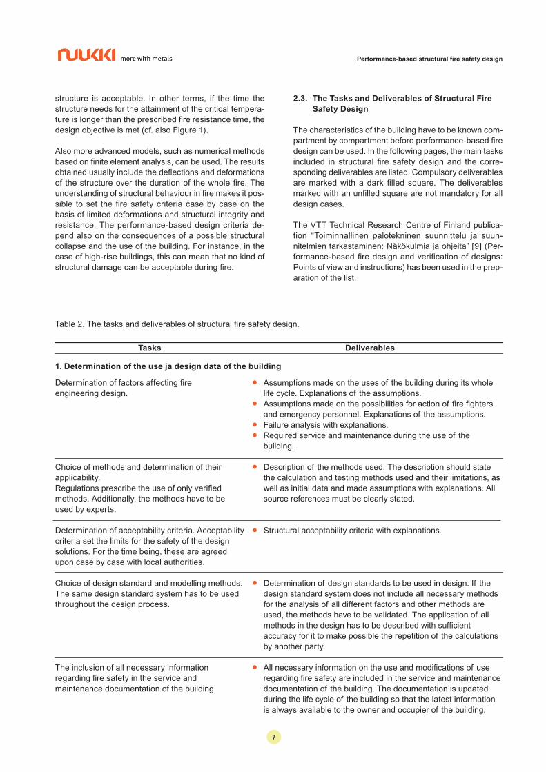
2.3. The Tasks and Deliverables of Structural Fire
Safety Design
The characteristics of the building have to be known com-partment by compartment before performance-based fi re design can be used. In the following pages, the main tasks included in structural fi re safety design and the corre-sponding deliverables are listed. Compulsory deliverables are marked with a dark fi lled square. The deliverables marked with an unfi lled square are not mandatory for all design cases.
The VTT Technical Research Centre of Finland publica-tion “Toiminnallinen palotekninen suunnittelu ja suun-nitelmien tarkastaminen: Näkökulmia ja ohjeita” [9] (Per-formance-based fi re design and verifi cation of designs: Points of view and instructions) has been used in the prep-aration of the list.
Table 2. The tasks and deliverables of structural fi re safety design.
Tasks Deliverables
1. Determination of the use ja design data of the building
Determination of factors affecting fi re engineering design.
Choice of methods and determination of theirapplicability. Regulations prescribe the use of only verifi ed methods. Additionally, the methods have to be used by experts.
Determination of acceptability criteria. Acceptability criteria set the limits for the safety of the design solutions. For the time being, these are agreed upon case by case with local authorities.
Choice of design standard and modelling methods. The same design standard system has to be used throughout the design process.
The inclusion of all necessary information regarding fi re safety in the service and maintenance documentation of the building.
● Assumptions made on the uses of the building during its whole life cycle. Explanations of the assumptions.
● Assumptions made on the possibilities for action of fi re fi ghters and emergency personnel. Explanations of the assumptions.
● Failure analysis with explanations.● Required service and maintenance during the use of the
building.
● Description of the methods used. The description should state the calculation and testing methods used and their limitations, as well as initial data and made assumptions with explanations. All source references must be clearly stated.
● Structural acceptability criteria with explanations.
● Determination of design standards to be used in design. If the design standard system does not include all necessary methods for the analysis of all different factors and other methods are used, the methods have to be validated. The application of all methods in the design has to be described with suffi cient accuracy for it to make possible the repetition of the calculations by another party.
● All necessary information on the use and modifi cations of use regarding fi re safety are included in the service and maintenance documentation of the building. The documentation is updated during the life cycle of the building so that the latest information is always available to the owner and occupier of the building.
Performance-based structural fi re safety design
67832_RUUKKI_ENG.indd 767832_RUUKKI_ENG.indd 7 19.9.2008 12:33:4819.9.2008 12:33:48
88
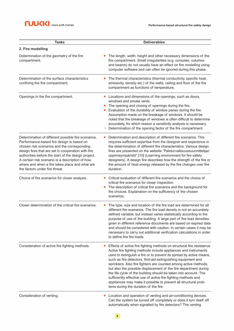
Tasks Deliverables
2. Fire modelling
Determination of the geometry of the fi re compartment.
Determination of the surface characteristics confi ning the fi re compartment.
Openings in the fi re compartment.
Determination of different possible fi re scenarios. Performance-based fi re design is based on chosen risk scenarios and the corresponding design fi res that are set in cooperation with fi re authorities before the start of the design project. A certain risk scenario is a description of how, where and when a fi re takes place and what are the factors under fi re threat.
Choice of fi re scenarios for closer analysis.
Closer determination of the critical fi re scenarios.
Consideration of active fi re fi ghting methods.
Consideration of venting.
● The length, width, height and other necessary dimensions of the fi re compartment. Small irregularities (e.g. consoles, columns and beams) do not usually have an effect on fi re modelling using computer software and can often be ignored during this phase.
● The thermal characteristics (thermal conductivity, specifi c heat, emissivity, density etc.) of the walls, ceiling and fl oor of the fi re compartment as functions of temperature,
● Locations and dimensions of the openings, such as doors, windows and smoke vents.
● The opening and closing of openings during the fi re.● Evaluation of the durability of window panes during the fi re.
Assumption made on the breakage of windows. It should be noted that the breakage of windows is often diffi cult to determine accurately, for which reason a sensitivity analysis is necessary.
❍ Determination of the opening factor of the fi re compartment.
● Determination and description of different fi re scenarios. This requires suffi cient expertise from the designer and experience in the determination of different fi re characteristics. Various design fi res are presented on the website “Paloturvallisuussuunnittelijan oppimisympäristö” [10] (Learning environment for fi re safety designers). A design fi re describes how the strength of the fi re or the amount of heat energy released by the fi re changes over fi re duration.
● Critical evaluation of different fi re scenarios and the choice of critical fi re scenarios for closer inspection.
● The description of critical fi re scenarios and the background for the choices. Explanation on the suffi ciency of the chosen scenarios.
● The type, size and location of the fi re load are determined for all different fi re scenarios. The fi re load density is not an accurately defi ned variable, but instead varies statistically according to the purpose of use of the building. A large part of fi re load densities given in different reference documents are based on expired data and should be considered with caution. In certain cases it may be necessary to carry out additional verifi cation calculations in order to defi ne the fi re loads.
● Effects of active fi re fi ghting methods on structural fi re resistance. Active fi re fi ghting methods include appliances and instruments used to extinguish a fi re or to prevent its spread by active means, such as fi re detectors, fi rst-aid extinguishing equipment and sprinklers. Also fi re fi ghters are counted among active methods, but also the possible displacement of the fi re department during the life cycle of the building should be taken into account. The suffi ciently effective use of active fi re fi ghting methods and appliances may make it possible to prevent all structural prob-lems during the duration of the fi re.
● Location and operation of venting and air-conditioning devices. Can the system be turned off completely or does it turn itself off automatically when signalled by fi re detectors? The venting
Performance-based structural fi re safety design
67832_RUUKKI_ENG.indd 867832_RUUKKI_ENG.indd 8 19.9.2008 12:33:4819.9.2008 12:33:48

99
Modelling of fi re scenarios.
Sensitivity analyses.
Reporting.
system may have a considerable infl uence on the availability of oxygen and fi re spread.
● The modelling of each fi re scenario that has been deemed critical is carried out with the chosen accuracy using appropriate methods and tools. At least the temperatures and heat fl uxes of the gas in the fi re compartment have to be given as functions of time and location during the whole duration of the fi re (also during the decreasing phase). The deliverables shall also include the thickness of the smoke layer at different times and the realised fi re heat release rate so that the verifi cation and evaluation of the calculation results is made possible.
● Description and explanation of the sensitivity analyses carried out on different affecting factors. The suffi ciency of the analyses shall be shown and conclusions made.
● Detailed report on fi re modelling, calculations and sensitivity analyses. Conclusions on the complete fi re modelling and analysis.
Tasks Deliverables
3. Calculation of heat transfer from fi re to structures
Determination of structural geometries.
Determination of heat transfer characteristics of the structural materials.
Defi nition of passive fi re protection.
Determination of critical structural members with regard to different fi re scenarios.
Choice of accuracy level of analyses.
Heat transfer analyses in different fi re scenarios.
● Dimensions and locations of individual load-carrying structural members.
● The heat transfer properties of different structural building materials as functions of temperature. Commonly necessary properties include heat conductivity, specifi c heat, density, surface emissivity and convection factor for the surface.
❍ Defi nition of all passive fi re protection methods and products, if they are used. Examples of passive fi re protection products for steel structures include fi re boards, fi re coatings, sprayed masses and other building materials, such as concrete. The protection provided by the fi re protection product shall be determined as function of temperature and/or time on the basis of the thickness and type of the protective layer. Depending on the design case, the resulting passive fi re protection is determined only after the basis of the complete fi re design process.
● Critical structural members are determined in the case of each different critical fi re scenario. Depending on the design case, these can be situated close to the fi re or at a distance from it. The designer may have to analyse several structural members in order to defi ne the critical case.
● Presentation on the accuracy level of the heat transfer analyses: 1D, 2D or 3D. In some cases, or for some building parts, several analyses of different accuracy levels may have to be carried out.
● Determination of the infl uence of shadowing effects on the heat transfer to different parts of structural members. Some calcula-tion softwares can carry this out automatically.
● Detailed report on the calculations taking into account passive and active fi re protection methods.
● Separate report on each critical fi re scenario.
Performance-based structural fi re safety design
67832_RUUKKI_ENG.indd 967832_RUUKKI_ENG.indd 9 19.9.2008 12:33:4819.9.2008 12:33:48

1010
Tasks Deliverables
Sensitivity analyses.
Reporting.
● Description and explanation on the sensitivity analyses carried out on different affecting factors. The suffi ciency of the analyses shall be shown and conclusions made.
● Detailed report on heat transfer, calculations and sensitivity analyses. Conclusions on the complete fi re modelling and analysis.
● Results of the temperature development calculations at the chosen accuracy for different structural members during the whole duration of the fi re.
Determination of fi re resistance requirements.
Determination of the properties of structural building materials.
Specifi cation of design standard system used for the structural analysis.
Determination of structural analysis model.
Determination of actions on structures during the fi re situation.
Structural analysis.
Sensitivity analyses.
Reporting.
● Required structural fi re resistance time.● Limits to the use of the structure.
● Strength and heat expansion properties as functions of tempera-ture for the load-carrying structural members according to the applicable EN- (or national) standard.
● Accurate and unambiguous determination of design standards and methods used during structural analyses. If the chosen standards system does not include instructions for the consid-eration of all necessary factors, and a different method is used, the reliability and applicability of this other method has to be established. Design standards belonging to different standardi-zation systems are generally not allowed to be used in combina-tion, i.e. if for instance actions are determined according to EN-standards, also the structural resistance shall be determined according to EN-standards.
● The sketching of a simplifi ed structural model. This can be done in a similar way as in normal temperature design. The connec-tions between members and other boundary conditions that may cause forced actions due to heat expansion shall be shown in the structural analysis model. The designer shall decide if the structural members are considered as individual members or if the complete structure is considered. This will also have an effect on the choice of analysis software, and vice versa.
● Determination of actions and combinations of actions on structures during the fi re situation according to the regulations and instructions given in the applicable design standard.
● Stability analysis. The verifi cation of the functioning of the complete structural frame.
● Design analysis in the accidental situation (fi re situation).● Calculation of defl ections and deformations.● Local stability analysis.● Design of connections.
● Description and explanation on the sensitivity analyses carried out on different affecting factors. The suffi ciency of the analyses shall be shown and conclusions made.
● Detailed report on analyses of structural behaviour, calculations and sensitivity analyses. Conclusions on the complete structural analysis.
4. Structural analysis
Performance-based structural fi re safety design
67832_RUUKKI_ENG.indd 1067832_RUUKKI_ENG.indd 10 19.9.2008 12:33:4819.9.2008 12:33:48

1111
Tasks Deliverables
2.4. Design Tools
Different types of special computer softwares are needed for performance-based design of buildings due to the dif-fi culty of the task. In the future, the objective will be to in-clude all fi re design related data and calculation methods in a product data model for the whole building, but for the time being, the use of several different computer pro-grammes at different phases of the design process is nec-essary.
Depending on the design case, fi re modelling can be car-ried out using zone models (e.g. OZone-software [11]) or computational fl uid dynamics (e.g. FDS [8]). After the fi re modelling has been done, the heat transfer to the struc-tures has to be modelled. In a simple case, this can be carried out using spreadsheet calculations and basic heat transfer equations, but a more advanced analysis using e.g. fi nite element analysis (FEA) is often needed. Finally, the resistance of structures has to be modelled using dif-ferent types of structural analysis and/or FEA-soft-wares.
3. Acceptability of Performance-Based Fire Design
3.1. Building Legislation Requirements
The use of performance-based fi re design is accepted in both Finnish and European building regulations. The Finn-ish Building Code Part E1 “Rakennusten paloturvallisuus, Määräykset ja ohjeet, 2002” (Fire Safety of Buildings, Re-quirements and guidelines, 2002) [12] section 1.3.2 states that
”The fi re safety requirement is deemed to be satisfi ed also when the building is design and built on the basis of performance-based fi re design that covers all likely events taking place in the building in question. The sat-isfaction of the requirements is verifi ed case by case taking into account the characteristics and use of the building.”
In the European design standard EN 1991-1-2 [6] dealing with actions on structures, it is prescribed that “[a]dvanced fi re models should take into account the following:
– gas properties;– mass exchange;– energy exchange.”
These factors are taken into account in both one-zone and two-zone models and in the more advanced fl uid dynamic models. In the same standard, it is furthermore stated that “[o]ne of the following models should be used:
– one-zone models assuming a uniform, time depend-ent temperature distribution in the compartment;
– two-zone models assuming an upper layer with time dependent thickness and with time dependent uni-form temperature, as well as a lower layer with a time dependent uniform and lower temperature;
– Computational Fluid Dynamic models giving the tem-perature evolution in the compartment in a complete-ly time dependent and space dependent manner.”
In the foreword to the European standard on the design of steel structures, EN 1993-1-2: 2005 Eurocode 3: Part 1.2 [13], the essential requirements for the limitation of fi re risks (the resistance of structures, the development of fi re and smoke and the general requirements for the safety of persons) given in Construction Products Directive 89/106/EEC are given, and also the following is stated:
“ Required functions and levels of performance can be specifi ed either in terms of nominal (standard) fi re re-sistance rating, generally given in national fi re regula-tions or by referring to fi re safety engineering for as-sessing passive and active measures.”
3.2. Required Documentation
Section 1.3.2 of the Finnish National Building Code Part E1 [12] lists the requirements set for the contents of the documentation on fi re design. These requirements have been included also in the list of tasks and deliverables given in Table 2.
4. Summary and Conclusions
Performance-based fi re safety design is an accepted methodology in both Finnish and European building regu-lations for the verifi cation of structural resistance in fi re conditions. A calculation procedure that takes into account the individual characteristics of the building and passive and active fi re protection methods has been developed in a joint European research project.
A realistic understanding of the behaviour of structures in fi re can be achieved and the overall safety of the building can be verifi ed by using performance-based fi re safety design. Through the more profound understanding of phe-nomena and a more precise analysis of structures in fi re, an equal to or higher safety level than with prescriptive fi re design can be obtained. The primary objective is to secure the safety of persons in the building and of emergency personnel and fi re fi ghters. The secondary objective is to prevent or reduce the economic, material and structural damages caused by fi res.
Performance-based structural fi re safety design
Reporting. ● Documentation of the behaviour and degrees of utilization of all different structural members at the chosen accuracy.
67832_RUUKKI_ENG.indd 1167832_RUUKKI_ENG.indd 11 19.9.2008 12:33:4819.9.2008 12:33:48

12
A fi re engineering briefi ng, where the contractor, building administration authorities and the designers agree on the fi re safety design process, should be held at the start of the project. It is the duty of the authorities to set the neces-sary requirements used in the design of the building.
This paper has been drafted by D.Sc. (Tech.) Olli Kaitila of the Finnish Constructional Steelwork Association on the basis of the referenced documents. The text has been commented upon by D.Sc. (Tech.) Jyri Outinen, Rautaruukki Ltd.; D.Sc. (Tech.) Jukka Hietaniemi, VTT Technical Research Centre of Finland; Professor, D.Sc. (Tech.) Markku Heinisuo, Tampere University of Technology; and Jussi Rahikainen, Director of Risk Management, Keski-Uusimaa Rescue Department.
References
[1] Schleich J-B., Cajot L-G., et al.: ”Competitive steel buildings through natural fi re safety concept.” ECSC Research 7210-SA/125,126,213,214,323,423,522,
623,839,937, B-D-E-F-I-L-NL-UK & ECCS, 1994-98, Draft Final Report July 2000 - Parts 1 to 5.
[2] Schleich J-B., Cajot L-G., et al.: ”Valorisation project – Natural fi re safety concept.” Final report. European Commission EUR 20349 EN, European Communities, 2002.
[3] RIL 221-2003 Paloturvallisuussuunnittelu. Suomen rakennusinsinöörien liitto RIL r.y. 2003. (Fire Safety Design, The Finnish Association of Civil Engineers, RIL, 2003.) In Finnish.
[4] EN 1363-1 Fire resistance tests. Part 1: General requirements. CEN European Committee for Standardization, Brussels 2000.
[5] DIFISEK Dissemination of Structural Fire Safety Engineering Knowledge, Draft Final Report, Research Programme of the Research Fund for Coal and Steel, 2005.
[6] EN 1991-1-2: 2003 Actions on structures – Part 1.2 : General Actions – Actions on structures exposed to fi re. CEN European Committee for Standardization, Brussels. 2003.
[7] Palotekninen erityissuunnittelu vyöhykemalleja käyttäen. Lehtimäki et al., Helsinki. Suomen Pelastusalan Keskusjärjestö. 58 s. + liitt. 16 s. (Tekniikka opastaa 12.) (Advanced Fire Engineering Design using Zone Modelling. Lehtimäki et al., Helsinki. Suomen Pelastusalan Keskusjärjestö SPEK (The Finnish National Rescue Association).
[8] Fire Dynamics Simulator (Version 5). User’s Guide. Kevin McGrattan & Bryan Klein (NIST), Simo Hostikka (VTT), Jason Floyd (Hughes Associates, Inc.), NIST National Institute of Standards and Technology in cooperation with VTT Technical Research Centre of Finland. NIST Special Publication 1019-5, January 8, 2008. www.fi re.nist.gov/fds
[9] Toiminnallinen palotekninen suunnittelu ja suunnitelmien tarkastaminen: Näkökulmia ja ohjeita. 2. versio, päivitetty 10.9.2007. (Performance-based fi re design and the verifi cation of design plans. Points of view and guidelines. 2. version, updated 10.9.2007.) Jukka Hietaniemi, VTT, 2007. In Finnish.
[10] Paloturvallisuussuunnittelijan oppimisympäristö. (Learning environment for fi re safety designers.) http://proxnet.vtt.fi /fi se/simon/Fise/opetusmateriaali/fi se_
etusivu.html Login name: fi se-reader. Password: June 1906. Mostly in Finnish.
[11] OZone V2.0 – Theoretical Description and Validation on Experimental Fire Tests. JF Cadorin, D. Pintea, JM Franssen, University of Liege, Belgium. 1st Draft, June 11, 2001.
http://www.argenco.ulg.ac.be/logiciel.php
[12] E1 Suomen Rakentamismääräyskokoelma. Rakennusten paloturvallisuus. Määräykset ja ohjeet 2002. Ympäristöministeriö 2002. (E1 Finnish National Building Code. Fire Safety of Buildings. Requirements and Guidelines 2002. Ministry of Environment 2002.) In Finnish.
[13] EN 1993-1-2: 2005 Eurocode 3: Design of steel structures – Part 1.2: General rules – Structural fi re design. CEN European Committee for Standardization, Brussels 2005.
Performance-based structural fi re safety design
Tämä ohjelehti on tarkistettu mahdollisimman huolellisesti. Emme kuitenkaan vastaa mahdollisista virheistä tai tietojen väärästäsoveltamisesta aiheutuneista välittömistä tai välillisistä vahingoista. Oikeudet muutoksiin pidätetään.
Copyright © 2008 Rautaruukki Oyj. Kaikki oikeudet pidätetään.Ruukki, More With Metals, Rautaruukki ja Ruukin tuotenimet ovat Rautaruukki Oyj:n tavaramerkkejä tai rekisteröityjä tavaramerkkejä.
• Ota yhteyttä asiakaspalveluumme
Myynti ja tekninen tuki puh. 020 59 11
Rautaruukki Oyj www.ruukki.com
67832_RUUKKI_ENG.indd 1267832_RUUKKI_ENG.indd 12 19.9.2008 12:33:4819.9.2008 12:33:48