Embed Size (px)
Citation preview
Jurnal Kejuruteraan 4(1992) 71-82
Performance and Working Space Requirement for Passive and Semi-active
Automobile Suspension
Mohd. lailani Mohd. Nor
ABSTRACT
In this paper computer simulation is used to study the performance of an automobile suspension system. The effect of tyre stiffness and unsprung mass on the performance in terms of riders comfort and the maximum working space requirement of the suspension system are also studied. Next, simple 'on-off' semi-active control rules are applied to the damper. These rules have been able to reduce the maximum working space required when compared to the passive suspension system. But, in terms of riders comfort the passive system is more superior. Finally, modified control rules are introduced and comparison on the performance and working space requirement are made with the suspension systems mentioned earlier. In general, the modified control rules have been able to increase riders comfort but larger working space are required.
ABSTRAK
Dalam kertas kerja ini penyelakuan komputer dijalankan untuk mengkaji prestasi sistem ampaian kereta. K£san kekakuan tayar dan jisim tak terpegas terhadap prestasi sistem ampaian kereta dari segi keselesoan penumpang dan ruang kerja maksima yang diperlukan juga dikaji. Selanjutnya, aturan-aturan mudah semi-aktif 'buka-tutup' dikenakan ke atas peredam. Aturan-aturan ini telah dapat mengurangkan ruang kerja maksima yang diperlukan berbanding dengan sistem ampaian pasif. Tetapi dari segi keselesoan penumpang prestasi sistem ampaian pasif adalah lebih baik. Akhirnya, aturan-aturan terubahsuai diperkenalkan dan perbandingan prestasi dan ruang kerja yang diperlukan dibuat dengan sistem-sistem ampaian yang telah dinyatakan sebelum ini. Pada keseluruhannya, aturanaturan terubahsuai berupaya meningkatkan keselesoan penumpang tetapi ruang kerja yang lebih besar diperlukan.
INTRODUCTION
This paper study the performance of an automobile suspension system. Beginning with a conventional passive suspension which typically consist of springs, dampers and masses that represent the real components which are in the form of pneumatic, hydraulic, or rubber devices. The elements are passive in the sense that no power source is required [I]. Next, a semiactive suspension system is developed. The elements in semi-active suspension system are the same as passive suspension with slight modification in which the damping coefficient can be modulated to adjust for different types of road conditions. This device can be conceptualized as a
"
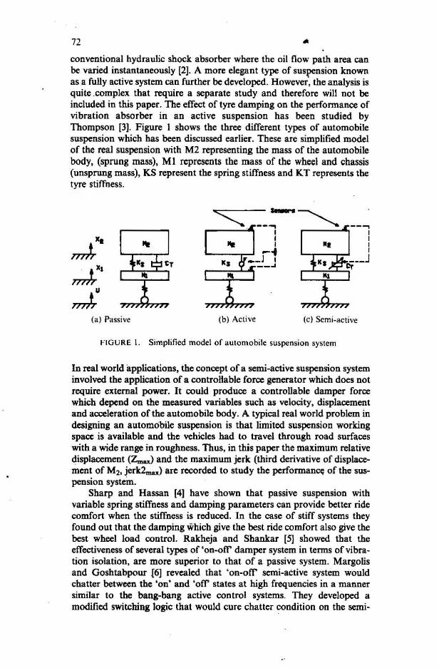
72 .. conventional hydraulic shock absorber where the oil flow path area can be varied instantaneously [2]. A more elegant type of suspension known as a fully active system can further be developed. However, the analysis is quite .complex that require a separate study and therefore will not be included in this paper. The effect of tyre damping on the performance of vibration absorber in an active suspension has been studied by Thompson [3). Figure I shows the three different types of automobile suspension which has been discussed earlier. These are simplified model of the real suspension with M2 representing the mass of the automobile body, (sprung mass), MI represents the mass of the wheel and chassis (unsprung mass), KS represent the spring stiffness and KT represents the tyre stiffness.
(a ) Passive (b) Active (c ) Semi-active
FIGURE 1. Simplified model of automobile suspension system
In real world applications, the concept of a semi-active suspension system involved the application of a controHable force generator which does not require external power. It could produce a controllable damper force which depend on the measured variables such as velocity, displacement and acceleration of the automobile body. A typical real world problem in designing an automobile suspension is that limited suspension working space is available and the vehicles had to travel through road surfaces with a wide range in roughness. Thus, in this paper the maximum relative displacement (Zm..) and the maximum jerk (third derivative of displacement of M2, jerk2.n..) are recorded to study the performance; of the suspension system.
Sharp and Hassan [4) have shown that passive suspension with variable spring stiffness and damping parameters can provide better ride comfort when the stiffness is reduced. In the case of stiff systems they found out that the damping which give the best ride comfort also give the best wheel load control. Rakheja and Shankar [5] showed that the effectiveness of several types of 'on-otT' damper system in terms of vibration isolation, are more superior to that of a passive system. Margolis and Goshtabpour {6) revealed that 'on-otT' semi-active system would chatter between the 'on' and '0tT' states at high frequencies in a manner similar to the bang-bang active control systems. They developed a modified switching logic that would cure chatter condition on the semi-
73
active 'on-of1' suspension system. However, \he performance of the modified switching are less superior at high excitation frequencies.
PERFORMANCE OF PASSIVE SUSPENSION
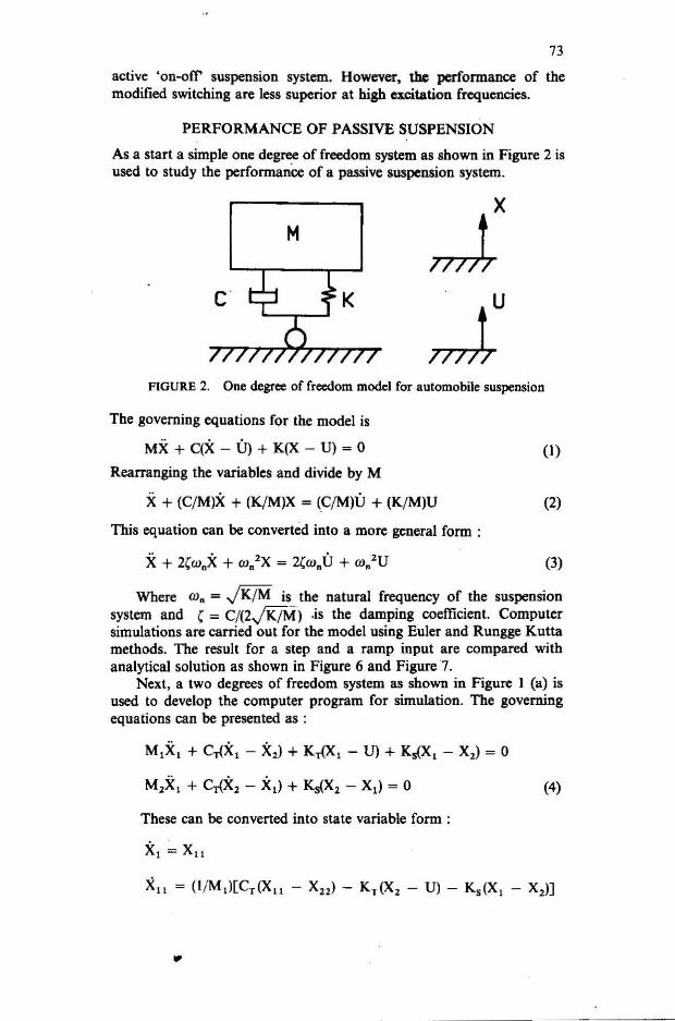
As a start a simple one degree of freedom system as shown in Figure 2 is used to study the performanCe of a passive suspension system.
M
FIGURE 2. One degree of freedom model for automobile suspension
The governing equations for the model is
MX + C(X - U) + K(X - U) = 0
Rearranging the variables and divide by M
X + (C/M)X + (K/M)X = (C/M)U + (K/M)U
This equation can be converted into a more general form :
X + 2Cw.X + w/X = 2Cw.U + w/U
(1)
(2)
(3)
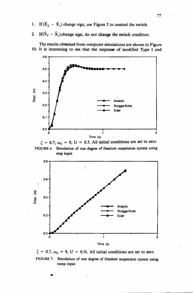
Where w. = J K/M is the natural frequency of the suspension system and ,= C/(2J K/M) .is the damping coefficient. Computer simulations are carried out for the model using Euler and Rungge Kutta methods. The result for a step and a ramp input are compared with analytical solution as shown in Figure 6 and Figure 7.
Next, a two degrees of freedom system as shown in Figure I (a) is used to develop the computer program for simulation. The governing equations can be presented as :
M,X, + C,{X, - X2) + K,{X, - U) + K.(X, - X2) = 0
M,X, + C,{X2 - X,) + K.(X2 - X,) = 0
These can be converted into state variable form :
x, = Xll
...
(4)
74 ... X, = Xl> XlI = (I /M,)[CT (Xli - X,,) - KT (X, - U) - Ks (X, - X,)] (5)
Fourth Order Rungge Kutta method is used to develop the algorithm for computer simulations due to the close agreement of this method with the analytical solution as shown in Figure 6 and Figure 7. The maximum relative displacement between M, and M, (z", .. ) which represents the maximum working space requirement for the suspension system and the maximum magnitude of the third derivative of displacement for M, (JERK2m"') are the two output recorded during simulations. Riders comfort is inversely proportional to the third derivative of the motion of M, (JERK2). .
M. J. Griffin and J. Griffin (7] showed that exposure to whole-body vibration to human for a long period of time can cause disability because of back disorders. The input function used to carry out the simulations can be presented by the following equation .
{
U 21f ~ (I - Cos ru"t) ; 0 :S: t :S: -2 aJn
U= 21f o ;t> -
ru"
(6)
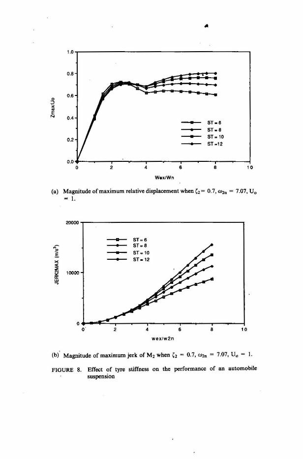
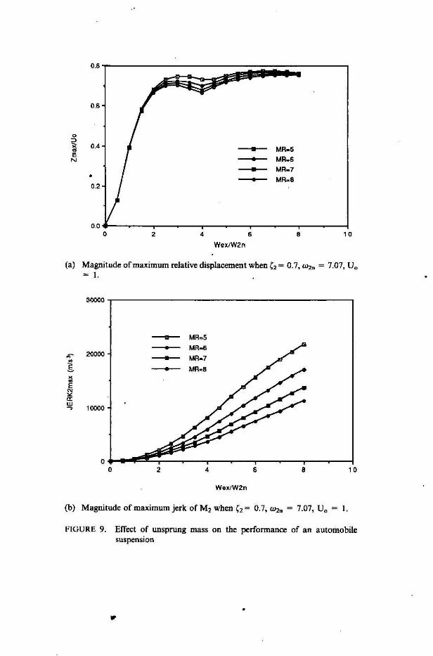
In real world application this input function represent a "bump" on the road and the duration of the " bump" can be controlled by changing the excitation frequency (ru.,.). Several simulations are carried out to study the performance of the automobile suspension by changing the ratio between tyre stiffness and spring stiffness denoted by the variable ST = K T/Ks. The results can be seen in Figure 9. As expected the magnitude of maximum jerk experienced by the automobile body is higher as the tyre stiffness is increased. The same statement can be made for the maximum working space required by the suspension system (z",.,.). Figure 10 shows that as the ratio between M, and M, denoted by MR = M,fM, is decreased the magnitude of maximum jerk experienced by M, and the magnitude of maximum relative displacement between M, and M, increase. However, the difference is quite small in the case of the maximum relative displacement as shown in Figure 9(b).
APPLICATION OF THE CONTROL LOGIC FOR SEMI-ACTIVE SUSPENSION
The objective of the control logic is to select suitable damper force such that an optimum performance can be achieved from the suspension system. During simulation the 'on' condition of the damper switch cores.ponds to a high value of damping factor ( , = 0.7, in which
(7)
75
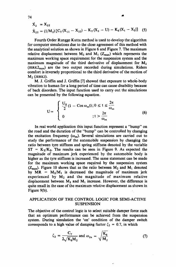
and the 'olr condition coressponds to a low value of damping factor '2 = 0.3. The first type of control logic (Type I) used absolute velocity and relative velocity of the alltomobile body as the condition parameters. The rule can be seen in Figure 3.
FIGURE 3. Control logic for Type II semi·active suspension
x, = absolute velocity of M2
(X, - X,) = relative velocity between M, and M,
From the above rule the actual damper force can be oresented as Fdampe,=-C,Oc, - X,)and the desired force, Fd .. ; .... = -CX,.ln order to minimise JERK2max any condition that can cause sudden change in vertical acceleration of the automobile body must be avoided, thus the modified switch control logic for Type I semi-active suspension is obtained. It can be stated a; :
l. If(X, - X,) changed sign, use Figure 3 to control the switch.
2. If only X, changed sign:
(A) If damper is 'on' and if the magnitude of the damper force is less than the magnitude of the spring force, use control logic as in Figure 3.
(B) Else, do not switch the damper.
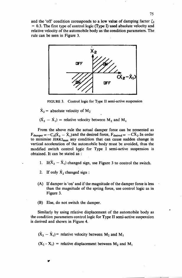
Similarly by using relative displacement of the automobile body as the condition parameters control logic for Type II semi-active suspension is derived and shown in Figure 4.
(X2 - X,)= relative velocity between M2 and M,
(X2 - X,) = relative displacement between M, and M,
..
76 ...
FIGURE 4. Control logic for Type II semi-active suspension
The modified control logic for Type II semi-active suspension is obtained by simply supressing the condition that may initiate a sudden change in the spring force. This can be stated as:
I. If(X2 - Xl)change sign, use control logic in Figure 4.
2. If (X2 - Xl) change sign, do not change the switch condition.
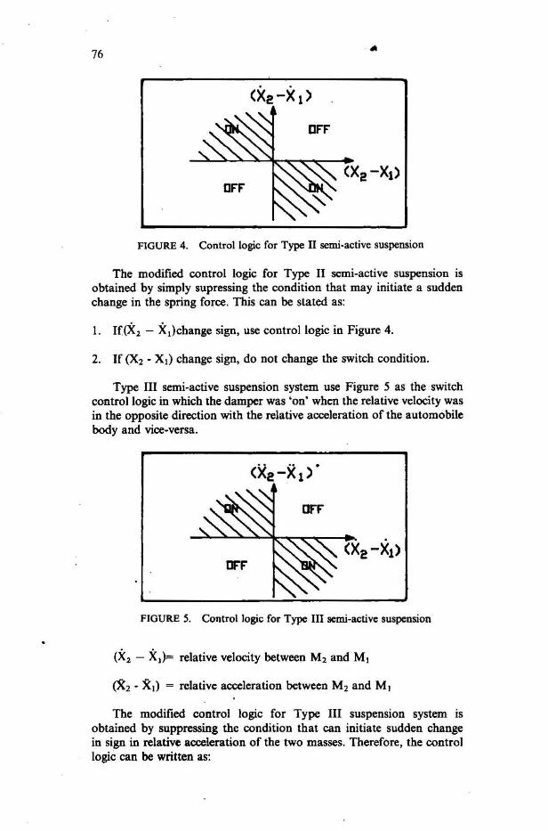
Type III semi-active suspension system use Figure 5 as the switch control logic in which the damper was 'on' when the relative velocity was in the opposite direction with the relative acceleration of the automobile body and vice-versa.
FIGURE 5. Control logic for Type III senti-active suspension
(X2 - Xl)= relative velocity between M2 and MI
eX2 - XI) = relative acceleration between M2 and MI
The modified control logic for Type III suspension system is obtained by suppressing the condition that can initiate sudden change in sign in relative acceleration of the two masses. Therefore, the control logic can be written as:
77
X ,) change sign, use Figure 5 to control the switch.
2. If(X2 - X,) change sign, do not change the switch condition.
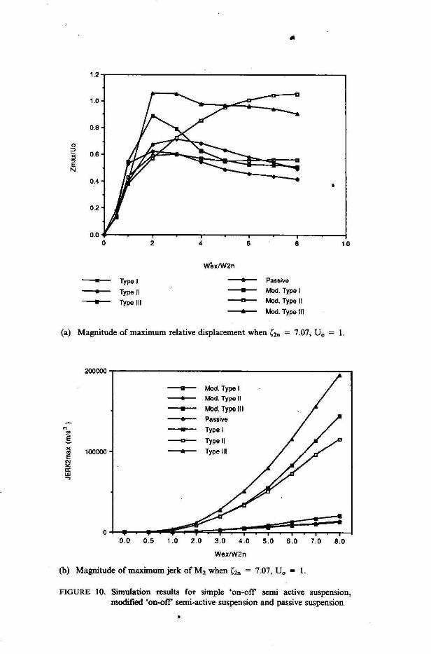
The results obmined from computer simulations are shown in Figure 10. It is interesting to see that the response of modified Type I and
0.6
0.5
0.'
I 0.3 0. .~ 0 - Analylic
0.2 - Rungge-Kutta - Euler
0.1
0 .0 0 2
TIme (8)
, ~ 0.7, Wn ~ 9, U ~ 0.5. All initial conditions are set to zero
FIGURE 6. Simulation of one degree of freedom suspension system using step input
0.8,.----------------------,
0.6
I 'li. 0.' 0 c - Analytic - Rungge-Kulta
0 .2 - Euler
0.0 ... 1:----~----...,....----~----_:f o 2
Time (s)
( ~ 0.7, w. = 9, U ~ 0.51. All initial conditions are set to zero
FIGURE 7. Simulation of one degree of freedom suspension system using ramp input
...
...
(a) Magnitude of maximum relative displacement when '2 ~ 0.7, "'2. ~ 7.07, Vo
- I.
20000
- 8T _ 6
~ - 5T - 8 0
§. - 5Tol0
x - 5T _ 12
~ 10000 c:: w -,
wex fw2n
(b) Magnitude of maximum jerk of M2 when C, - 0.7, "'2n ~ 7.07, Vo ~ I.
FIGURE 8. Effect of tyre stiffness on the performance of an automobile suspension
WexfW2n
(a) Magnitude of maximum relative displacement when', = 0.7, OJ,. = 7.07, Va = I.
3~0,--------------------------------------------,
- MR=5 - MR",6 ..- 20000 - MR.7
~ - MR-S x ~
E N
'" a: w
10000 ..,
WexlW2n
(h) Magnitude of maximum jerk ofM, when ,,= 0.7, OJ,. = 7.07, Va = I. FIGURE 9. Effect of unsprung mass on the performance of an automobile
suspension
'"
1.2
1.0
0.8
0 :>
" 0.6 ~ E N
0.4
0.2
----- Type I
- Type II
- Typelll
...
W'exlW2n
• Passive
• Mod. Type I --a-- Mod. Type II
& Mod. Type 111
(a) Magnitude of maximum relative displacement when {2n = 7.07. Uo 1.
200000
" • ~ • 100000 ~ E
N >< a: UJ ~
0.0 0.5
- Mod. Type I - Mod. Type II - Mod. Type III - Passive - Type I
---0-- Type II - Type III
1.0 2.0 3.0 4.0 5.0 6.0 7.0 8.0
Wex/W2n
(b) Magnitude of maximum jerk of M2 when C2n ~ 7.07, Vo ~ I.
FIGURE 10. Simulation results for simple 'on-off' semi active suspension, modified 'on-off' semi-active suspension and passive suspension
81
modified Type II suspension systems arc indentical. In general, the modified control logic have been able to reduce the magnitude of JERK2max significantly and modified Type ill is slightly superior than the passive suspension. But at high excitation frequencies the working space requirement for all the three types of modified control logic are almost twice as large compared to the passive suspension.
CONCLUSION
It has been shown that the simple 'on-olr control switch applied on the damper will increase the magnitude of maximum jerk experienced by the automobile body significantly and the maximum working space requirement has been reduced slightly. In goneral, modifed control logics on the damper are able to reduce the magnitude of maximum jerk experienced by the automobile body below the result obtained from the original simple 'on-olr control rule for all the three types of semi-active suspension. But the working space required by the modified control logic are twice as much as that is needed for the passive suspension. The limitations of 'on-olr semi-active damper obtained from this study are similiar to the experimental study carried out by K J. Krasnicki (8).
Finally, if the tyre stiffness'increase maximum jerk experienced by the automobile body and maximum working space required by the automobile suspension will also increase. But as the weight of the unsprung mass decreases, the magnitude of maximum jerk experienced by the automobile body also decrease without significant effect on the maximum space requirement.
M, M2 XI X2
KT Ks CT Uo rocx
C2 ron
z",ax JERK2max -
ST MR
..
NOTATION unsprung mass mass of automobile body displacement of unsprung weights displacemellt of automobile body tyre stiffness 'spring stiffness damping coefficient maximum input displacement excitation frequency damping ratio natural frequency of the suspension system maximum relative between M2 and MI maximum jerk experienced by the automobile body ratio between Type stiffness and spring stiffness ratio between sprung mass and unsprung mass
82 ... REFERENCES
I. D. Karnopp, M. J. Crosby & R. A. Harwood. 1974. Vibration Control Using Semi-Active Force Generators. Journal of Engineering for Industry. Transaction of the ASME. May: 619-626.
2. D. L. Margolis. 1973.The Approximate Frequency Response of Semi-Active Systems Requiring No Computer. Journal of Franklin Institute. 316(3): 261-71. Sept.
3. A. G. Thompson. 1989. The Effect ofTyre Damping on the Performance of Vibration Absorbers in an Active Suspension. Journal of Sound and Vibra-tion. 133(3) 457-465. .
4. R. S. Sharp & S. A. Hassan. 1986. Evaluation of Passive Automotive Suspension Systems With Variable Stiffness and Damping Parameters. Vehicle System Dynamic. 15(6): 335-350.
5. S. Rakbeja & S. Sankar. 1986. Effectiveness of On-Off Damper in Isolatiog Dynamical System. The Shock and Vibration Bulletin. Pt. 2, Aug.: 147-157.
6. D. L. Margolis & M. Goshtasbpour. 1984. The Chatter of Semi-Active On-Off Suspension And Its Cure, Vehicle System Dynamics. 13: 129-144.
7. M.1. Griffin & 1. Griffin. 1989. "Human Response to Vibration. Journal of Sound and Vibration. 133(3): 529-531.
8. E. J. Krasnicki. 1980. The Experimental Perfomance on "on-off' Active Damper. The Shock and Vibration Bulletin. 51: 125-131.
Jabatao Kejuruteraan Mekanik dan Bahan Fakulti Kejuruteraan Universiti Kebaogsaao Malaysia 43600 UKM Bangi Selangor D. E .. Malaysia