Embed Size (px)
Citation preview
International Journal of Current Engineering and Technology E-ISSN 2277 – 4106, P-ISSN 2347 – 5161 ©2016 INPRESSCO®, All Rights Reserved Available at http://inpressco.com/category/ijcet
Research Article
2130| International Journal of Current Engineering and Technology, Vol.6, No.6 (Dec 2016)
Passive cooling of a space by solar chimney
Majid H. Majeed†* and Ali A. Mishaal†
†Engineering technical College- Middle Technical University–Baghdad, Iraq
Accepted 30 Nov 2016, Available online 07 Dec 2016, Vol.6, No.6 (Dec 2016)
Abstract Experimental and numerical study of a passive wall solar chimney with evaporative cooling used for cooling application in Iraqi climate was investigated. The model was used made of wood with dimensions of (2.5m 1.29m
1.07m) and copper absorber plate. The numerical simulation was done by ANSYS software for May and June. It was found that, the using of evaporative cooling and passive cooling solar chimney decreased the temperature inside the space by 8.5°C lower than ambient temperature experimentally and 5.8°C numerically. Keywords: Natural ventilation, solar chimney, Passive cooling, Similitude. 1. Introduction
1 The solar radiation in Mediterranean countries during summer months is very intensive, also the ambient temperature is more than 40°C. The combination of this reality with conventional energy source limitations for availability, cost and the increased awareness of environmental issues, have led to renewed interest in passive building design. Passive heating, in which part or all of the building is a solar collector, has been widely examined, passive cooling, however, remains largely unexplored. Among the applications of these technologies, particularly appropriate for the hot-humid climates of Mediterranean region is solar chimney which is an effective technique to reduce the temperature inside a building as well as to provide natural ventilation, which helps in lowering the humidity and achieving comfortable conditions inside the space. A solar chimney generates air movement by buoyancy forces, in which hot air rises and exits from the top of the chimney, drawing cooler air through the building in continuous cycle. Its application in buildings may provide the required ventilation while simultaneously covers part of the heating and cooling requirements. The thermally induced air flow depends on the difference in air density between the inside and outside of the solar chimney. In the ways to increase the solar heat absorption and ventilation rate, the replacement of the south-facing wall of the solar chimney with glazing, the blackening of the interior of other walls and the insulation of the exterior can be considered. Many researchers investigate the use of solar chimney, with different configurations, in natural
*Corresponding author: Majid H. Majeed
ventilation improvement for cooling applications. (Jiang et al. 2001) have presented a solar house built in a southern city of China where the summer is long, hot and humid. A multifunctional solar system has been used and a method for indoor ventilation has been proposed. The design included double walls and a triple roof in order to remove heat by the ventilation of the building envelope. (Amer 2006) examined the various passive cooling techniques on a scaled cubic building with a volume of 1m3. The south-facing solar chimney, measuring 2.0m in height and 0.5m in width, led to a 6.5oC to 10.4oC drop in the room temperature when compared to the base case and gave a temperature which on average, was 1.0oC higher than the ambient temperature. (Bacharoudis et al. 2007) predicted the air velocity and temperature within a solar chimney using two-dimensional, incompressible and steady state FLUENT simulations with Boussinesq approximation. The solar chimney measured 0.05m in depth and 4.00m in height. The outer and inner walls of the solar chimney were assumed to be isothermal; the temperature of the outer wall ranged from 45oC to 70oC while the inner wall was kept constant at 27oC. Various different turbulence models were examined and the realizable k-ε model was found to be the most suitable. Furthermore, simulated results predicted that increasing the outer wall temperature caused an increase in the volume flowrate and air temperature. (Chungloo and Limmeechokchai 2007) conducted experiments on detached wooden one-story rooms measuring 3.8m by 2.8m by 2.4m to examine the influences of solar chimney tilted 45o with a depth of 0.15m. Compared to the base case, results in July showed that the wooden solar chimney caused a temperature drop of 1.0oC to 1.3oC within the room during the hot afternoon.
Majid H. Majeed and Ali A. Mishaal Passive cooling of a space by solar chimney
2131| International Journal of Current Engineering and Technology, Vol.6, No.6 (Dec 2016)
Nomenclature ( ) ( ) ( ⁄ )
( ⁄ ) ( ⁄ ) ( ⁄ ) ( ⁄ ) ( ) s ( ) ( ) ( ⁄ ) ( )
( ) ( ⁄ )
( ⁄ )
Using a discharge coefficient of 0.4 with solar irradiance between 400W/m2 to 1000W/m2, the volume flowrate in July was found to range from 0.0008m3/s to 0.0120m3/s in July, giving an air change rate of 1.13ACH to 2.26ACH. (Poshtiri et al. 2011); compared between two low-energy systems were used to enhance passive cooling and natural ventilation in a solar room. First system consists of a Solar Chimney (SC) and an Evaporative Cooling Cavity (ECC) and the second system includes a Solar Chimney (SC) and an Earth-to-Air Heat exchanger (EAHE). As a result it was found that, when the cooling demand of the room is 116W and the relative humidity was lower than 50%, the SC-ECC system can make acceptable indoor air conditioning even at ambient 40°C, with weak solar intensity of 200 . It was also found that, the proposed system can provide thermal comfort conditions even during the night with zero solar radiation. The results about SC-EAHE system show that when the ambient temperature and cooling demand were high (1500W), proper configurations could provide good indoor condition even at poor solar intensity of 100 W/m2 and high ambient air
temperature of 50oC. Comparative survey shows the SC-EAHE system was the best choice for buildings with poor insulation at day time, but SC-ECC system was better for night ventilation and cooling purposes especially in arid climates. (Abdallah et al. 2013); developed an integration of direct evaporative cooling tower with a solar chimney multi-zone thermal ventilation model. Simulation was done using commercial couple multi-zone airflow under COMIS-TRNSYS software to assess natural ventilation and indoor thermal comfort. As a result, it was found that, the system generates a 130.5 m3/h under the effect of solar radiation only and minimum 2 air change per hour without pressure coefficient which was considered the minimum requirement of air change per hour. The results showed that the new integrated system interacts with the building envelope and weather conditions to achieve a decrease in indoor temperatures that reach 10°C to 11.5°C compared to outdoor temperatures. (Tashtoush et al. 2013); studied a mathematical simulation of a system that was driven by a solar chimney equipped with Parabolic Solar Concentrator (PSC) in order to cool buildings by using an Evaporative Cooling Cavity (ECC). The Capability of the system to meet the standards and requirements were considered in order for this study to be applicable in many fields (residential, industrial or agricultural). Mathematical modeling and simulation were performed to illustrate the effect of changing parameters regarding geometry and dimensions, ambient temperature, relative humidity, heat and mass transfer rate and others. The solar chimney was designed by using parabolic solar concentrator to increase the efficiency of this system. The simulation showed that the system was capable of providing good temperature reduction even with low solar intensity (200 W/m²). It was found that the system could be used for residential and agricultural applications to provide thermal comfort conditions in hot air and dry climates. An experimental and numerical model of a solar chimney was proposed by (Imran et al. 2015) to predict its performance under varying geometrical features in Iraqi environmental conditions. It was conducted using a single solar chimney installed on the roof of a 12 m3 room volume. The chimney was 2 m long; 2 m wide has three gap thicknesses (50, 100 and 150) mm. As a result, the highest rate of ventilation was found to be 30 air changes per hour with a solar radiation of 750 W/m2, inclined surface angle of 60o, aspect ratio of 13.3 and chimney length of 2 m. Also at the same solar radiation the maximum air velocity was 0.8 m/s at 50 mm air gap. So that the air flow increased with the increased of the gap thickness between absorber and glass covers.
2. Experimental model
The outdoor experimental study conducted at Baghdad on the roof of laboratory building in Technical Collage of Baghdad (9 m) height for a building latitude and
Majid H. Majeed and Ali A. Mishaal Passive cooling of a space by solar chimney
2132| International Journal of Current Engineering and Technology, Vol.6, No.6 (Dec 2016)
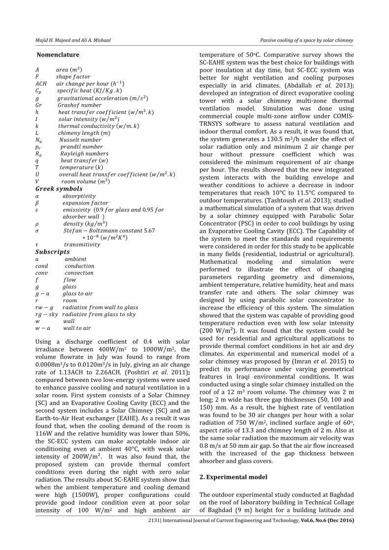
longitude 33° north and 44° east, facing south in vertical position. A suitable scale factor to find the dimensions of the model is assumed to be 3:1, let the dimensions of the room under study be (7.5m3.87m3.21m). Since the scale factor is 3 then the dimension of model is (2.5m 1.29m 1.07m). The reduced scale model used in this study is made of wood 18 mm thickness with a thermal conductivity about (0.522 ). The wood wall of the reduced model was connected by screw on an iron frame. The study model has an open window in the north wall with 10 cm height from the floor and connected with solar chimney on the south wall as shown in Fig. 1. The absorber plate was made of copper with 1 mm thickness. The absorber plate was covered by a commercial glass panel of 4 mm thickness fitted on iron frame. The absorber plate which its length 1.14 m and the inclination angle 20°.
(a) (b)
(c)
(d) (e)
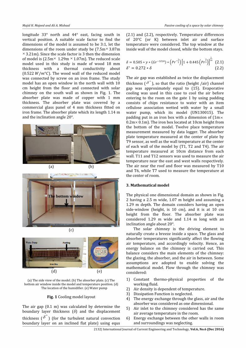
(a) The side view of the model. (b) The absorber plate. (c) The
bottom air window inside the model and temperature position. (d) The location of the humidifier. (e) Water pump
Fig. 1 Cooling model layout The air gap (0.1 m) was calculated by determine the boundary layer thickness (δ) and the displacement
thickness (* ) (for the turbulent natural convection
boundary layer on an inclined flat plate) using equs
(2.1) and (2.2), respectively. Temperature differences of 20°C (or K) between inlet air and surface temperature were considered. The top window at the inside wall of the model closed, while the bottom stays.
( ) (
) * (
)+
(2.1)
(2.2) The air gap was established as twice the displacement
thickness (* ), so that the ratio (height /air) channel
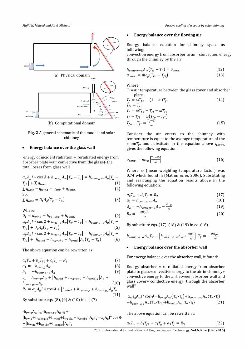
gap was approximately equal to (15). Evaporative cooling was used in this case to cool the air before entering to the room on the gate 1 by using padding consists of chips resistance to water with an item cellulose association wetted with water by a small water pump, which its model (UN130015). The padding put in an iron box with a dimension of (1m0.2m0.1m). The iron box located at 10cm height from the bottom of the model. Twelve place temperature measurement measured by data logger. The absorber plate temperature measured at the center of plate by T9 sensor, as well as the wall temperature at the center of each wall of the model by (T1, T2 and T4). The air temperature measured at 10cm distance from each wall. T11 and T12 sensors was used to measure the air temperature near the east and west walls respectively. The air near the roof and floor was measured by T10 and T6, while T7 used to measure the temperature at the center of room. 3. Mathematical model The physical one dimensional domain as shown in Fig. 2 having a 2.5 m wide, 1.07 m height and assuming a 1.29 m depth. The domain considers having an open side-window (height, is 10 cm), and it is at 10 cm height from the floor. The absorber plate was considered 1.29 m wide and 1.14 m long with an inclination angle about 20°. The solar chimney is the driving element to naturally create a breeze inside a space. The glass and absorber temperatures significantly affect the flowing air temperature, and accordingly velocity. Hence, an energy balance on the chimney is carried out. This balance considers the main elements of the chimney: the glazing, the absorber, and the air in between. Some assumptions are adopted to enable solving the mathematical model. Flow through the chimney was considered:
1) Constant thermo-physical properties of the working fluid.
2) Air density is dependent of temperature. 3) Dissipation Function is neglected. 4) The energy exchange through the glass, air and the
absorber was considered as one dimensional. 5) Air inlet to the chimney considered has the same
air average temperature in the room. 6) Energy exchange between the other walls in room
and surroundings was neglecting.
The bottom window
Majid H. Majeed and Ali A. Mishaal Passive cooling of a space by solar chimney
2133| International Journal of Current Engineering and Technology, Vol.6, No.6 (Dec 2016)
(a) Physical domain
(b) Computational domain
Fig. 2 A general schematic of the model and solar
chimney Energy balance over the glass wall
[ ] [
] ∑ (1)
∑ (2)
So:
∑ ( ) (3)
Where: (4)
[ ] [
] ( ) (5)
[ ] [
] [ ] ( ) (6)
The above equation can be rewritten as: (7)
(8)
(9)
[ ]
(10)
[ ]
… (11) ( ) ( ) ( ) ( )
[ ]
[ ]
Energy balance over the flowing air Energy balance equation for chimney space as following: ( ) (12)
( ) (13)
Where: ( ) (14)
( )
(15)
Consider the air enters to the chimney with temperature is equal to the average temperature of the room , and substitute in the equation above gives the following equation:
*
+ (16)
Where (mean weighting temperature factor) was 0.74 which found in (Mathur et al. 2006). Substituting and rearranging the equation results above in the following equation: (17)
(18)
(19)
(20)
( ) ( ) ( ) ( )
*
+
Energy balance over the absorber wall
For energy balance over the absorber wall, it found: Energy absorber = re-radiated energy from absorber plate to glass+convective energy to the air in chimney+ convective energy to the airbetween absorber wall and glass cover+ conductive energy through the absorber wall"
( ) ( )
- ( - ) ( - ) (21)
The above equation can be rewritten a (22)
Majid H. Majeed and Ali A. Mishaal Passive cooling of a space by solar chimney
2134| International Journal of Current Engineering and Technology, Vol.6, No.6 (Dec 2016)
[ ] (23)
(24) (25)
[ ] (26) (27)
By substitute eqs.(22),(23),(24),(25) & (26) in eq.(21)
[ ]
[
]
The above three equations, (7), (16) & (21) are solved iteratively by using the EES software. The temperatures of absorber plate and glass obtained. The air flowing properties are considered to varying with its temperature. Therefore, the properties are changed with the converged values of the temperature. The heat transfer coefficients mentioned in the three equations above can be determined based on the Stefan Boltzmann relation; Fourier law of conduction and Newton’s cooling law. These coefficients are as listed below:
( )(
)
(
)(
)(
)
Where: the shape factor is considered unity.
The absorptivity of glass was taken as 0.06, transmissivity as 0.84, and wall absorptivity as 0.95.The temperature of sky and wind coefficient can be found in (Duffie and Beckman, 1974) as:
The coefficient of conductive heat transfer for the absorber wall and glass∶
The air flowing in the solar chimney carries convective energy from the absorber walls and glass. So, the convective heat transfer coefficients between air and both walls are:
In natural ventilation, it is much significant to know air exchange rate, the ratio of the air volume flow rate to the room volume. This expression is known as the air change per hour (ACH). This index is defined by ASHRAE as:
In this study, the room volume was considered (3.45 m3) to simulate an actual room size. However, it should be noted that the room model volume could be used to obtain ACH. Heat transfer in cooling space Below are the correlations used to estimate the heat transfer coefficients between air flowing in the chimney and both glass wall and absorber wall (Mathur et al. 2006). The empirical relation for the Nusselt number is obtained from (Holman, 1981) for natural convection on vertical plates:
Where: means the surface average temperature. It is equal to when the system is the glass wall, and equal
to Tw when the system is the absorber wall.
( )
( )
( )
[ *
+ ⁄]
⁄
4. Numerical model
The numerical simulation of the thermal and fluid dynamic behavior of the solar chimney has been done with ANSYS software which solves the Navier Stokes equations. ANSYS software is used for numerical simulation of real sized 2-D room with solar chimney. The room connected to the chimney is (1.292.51.07) m, which was with an air inlet at its bottom in and air outlet from the top of chimney. The solar chimney was simulated at 20° for summer. The triangle space at the back of absorber plate area was (0.391.29) m and 1.42m height. The cooling mode is turbulent flow ( ) constant absorber plate about 70°C. The temperature and velocity of air inlet to the model was taken for range about (35-75) °C and (0.2-1) , respectively. The outdoor design condition simulated for May, June and July for some days in each month. A structured mesh has been developed by gambit software. The mesh of the final study has more than 36527 cells with uniformly square shape, which allows a substantial spatial resolution, because of the inclined wall of triangle the mesh size reduced to minimize the error, as shown in Fig. 3.
Majid H. Majeed and Ali A. Mishaal Passive cooling of a space by solar chimney
2135| International Journal of Current Engineering and Technology, Vol.6, No.6 (Dec 2016)
To analyze the fluid-dynamic and thermal behavior of the solar chimney, simulations in steady state have been carried out, varying the solar radiation levels increasingly from 600 W/m2 up to 1200 W/m2. These values correspond to the radiation at right angles with the glass exterior surface, although the boundary condition has been applied with an inclination fitting the latitude of the experiment location.
Fig. 3 The numerical model mesh
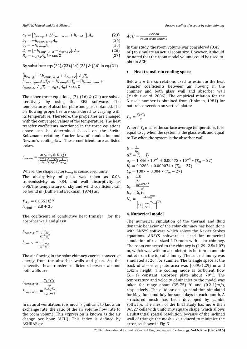
5. Results and Discussion 5.1 Comparison of Numerical and Experimental Results The numerical results for the cooling mode for the air temperature near the north wall is simulated for May and June. The numerical temperature greater than experimental in May with maximum value ranged from 1.65°C to 3.28°C as shown in Fig. 4. While in June the difference between numerical and experimental increased and reaches to 4.2°C due to higher ambient temperature, which be greater than 35°C and reach to 38.5°C afternoon and its noticed that the numerical temperature has the same behaviour with the ambient temperature, as shown in Fig. 5.
(a) 19-5-2016
(b) 26-5-2016
Fig. 4 Air numerical temperature near the north wall
for some days in May
Fig. 5 Air numerical temperature near the north wall in 2-6-2016
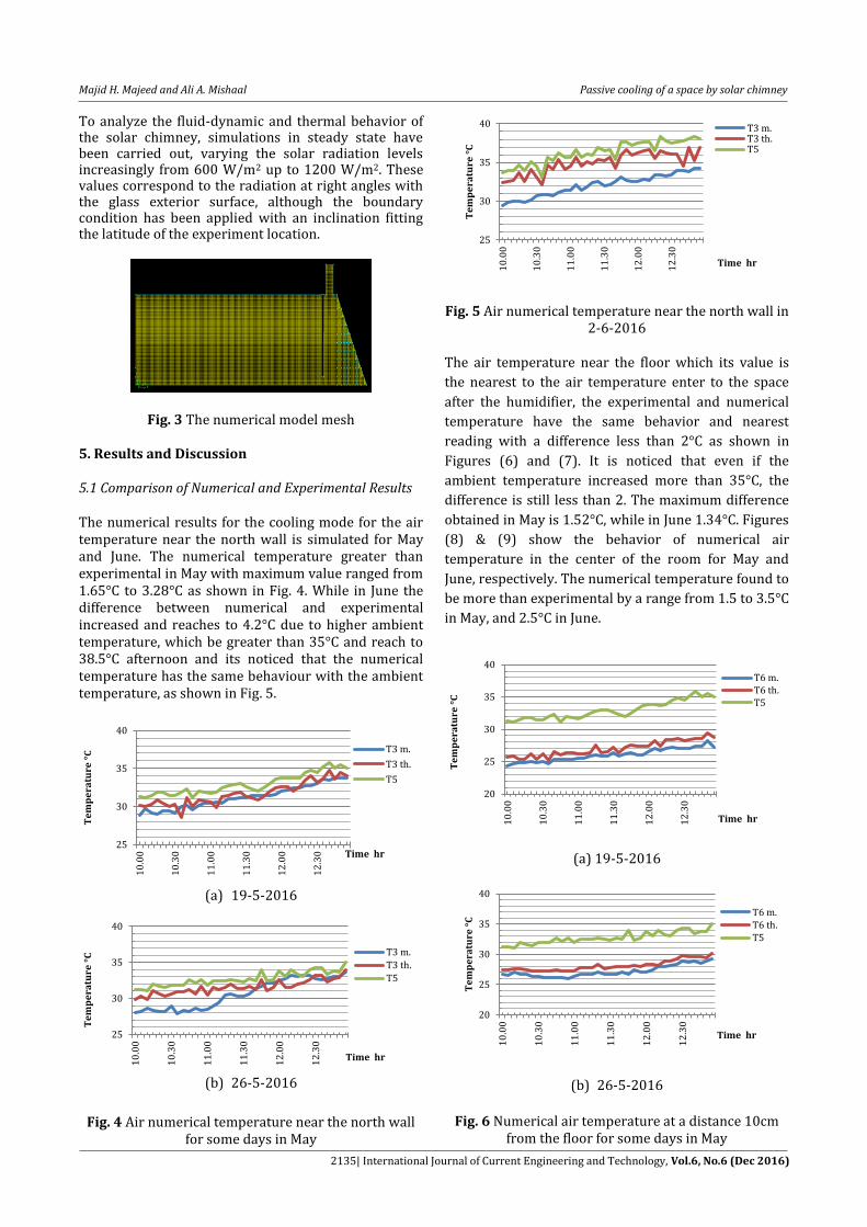
The air temperature near the floor which its value is
the nearest to the air temperature enter to the space
after the humidifier, the experimental and numerical
temperature have the same behavior and nearest
reading with a difference less than 2°C as shown in
Figures (6) and (7). It is noticed that even if the
ambient temperature increased more than 35°C, the
difference is still less than 2. The maximum difference
obtained in May is 1.52°C, while in June 1.34°C. Figures
(8) & (9) show the behavior of numerical air
temperature in the center of the room for May and
June, respectively. The numerical temperature found to
be more than experimental by a range from 1.5 to 3.5°C
in May, and 2.5°C in June.
(a) 19-5-2016
(b) 26-5-2016
Fig. 6 Numerical air temperature at a distance 10cm
from the floor for some days in May
25
30
35
40
10
.00
10
.30
11
.00
11
.30
12
.00
12
.30
Te
mp
era
ture
°C
Time hr
T3 m.
T3 th.
T5
25
30
35
40
10
.00
10
.30
11
.00
11
.30
12
.00
12
.30
Te
mp
era
ture
°C
Time hr
T3 m.
T3 th.
T5
25
30
35
40
10
.00
10
.30
11
.00
11
.30
12
.00
12
.30
Te
mp
era
ture
°C
Time hr
T3 m.T3 th.T5
20
25
30
35
40
10
.00
10
.30
11
.00
11
.30
12
.00
12
.30
Te
mp
era
ture
°C
Time hr
T6 m.T6 th.T5
20
25
30
35
40
10
.00
10
.30
11
.00
11
.30
12
.00
12
.30
Te
mp
era
ture
°C
Time hr
T6 m.T6 th.T5
Majid H. Majeed and Ali A. Mishaal Passive cooling of a space by solar chimney
2136| International Journal of Current Engineering and Technology, Vol.6, No.6 (Dec 2016)
Fig. 7 Numerical temperature at a distance 10cm from the floor in 2-6-2016
(a) 19-5-2016
(b) 26-5-2016
Fig. 8 Numerical air temperature in the center of room
for some days in May
Fig. 9 Numerical air temperature in the center of room
in 2-6-2016
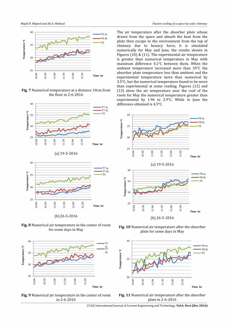
The air temperature after the absorber plate whose drawn from the space and absorb the heat from the plate then escape to the environment from the top of chimney due to bouncy force, it is simulated numerically for May and June, the results shown in Figures (10) & (11). The experimental air temperature is greater than numerical temperature in May with maximum difference 4.1°C between them. When the ambient temperature increased more than 35°C the absorber plate temperature less than ambient and the experimental temperature more than numerical by 3.5°C, but the numerical temperature found to be more than experimental at some reading. Figures (12) and (13) show the air temperature near the roof of the room for May the numerical temperature greater than experimental by 1.96 to 2.9°C. While in June the difference obtained is 4.5°C.
(a) 19-5-2016
(b) 26-5-2016
Fig. 10 Numerical air temperature after the absorber plate for some days in May
Fig. 11 Numerical air temperature after the absorber
plate in 2-6-2016
25
30
35
40
10
.00
10
.30
11
.00
11
.30
12
.00
12
.30
Te
mp
era
ture
°C
Time hr
T6 m.
T6 th.
T5
25
30
35
40
10
.00
10
.30
11
.00
11
.30
12
.00
12
.30
Te
mp
era
ture
°C
Time hr
T7 m.T7 th.T5
25
30
35
40
10
.00
10
.30
11
.00
11
.30
12
.00
12
.30
Te
mp
era
ture
°C
Time hr
T7 m.T7 th.T5
25
30
35
40
10
.00
10
.30
11
.00
11
.30
12
.00
12
.30
Te
mp
era
ture
°C
Time hr
T7m.T7th.
25
30
35
40
10
.00
10
.30
11
.00
11
.30
12
.00
12
.30
Te
mp
era
ture
°C
Time hr
T8 m.
T8 th.
T5
25
30
35
40
10
.00
10
.30
11
.00
11
.30
12
.00
12
.30
Te
mp
era
ture
°C
Time hr
T8 m.
T8 th.
T5
30
35
40
10
.00
10
.30
11
.00
11
.30
12
.00
12
.30
Te
mp
era
ture
°C
Time hr
T8 m.
T8 th.
T5
Majid H. Majeed and Ali A. Mishaal Passive cooling of a space by solar chimney
2137| International Journal of Current Engineering and Technology, Vol.6, No.6 (Dec 2016)
(a) 19-5-2016
(b) 26-5-2016
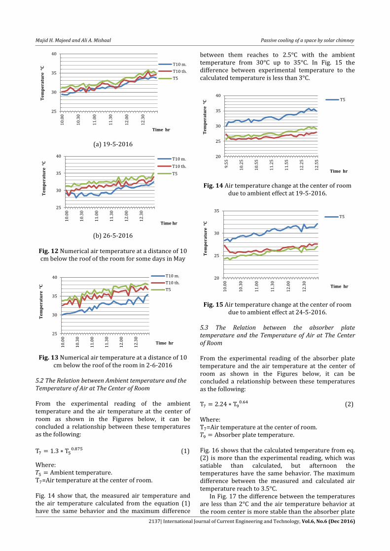
Fig. 12 Numerical air temperature at a distance of 10 cm below the roof of the room for some days in May
Fig. 13 Numerical air temperature at a distance of 10
cm below the roof of the room in 2-6-2016 5.2 The Relation between Ambient temperature and the Temperature of Air at The Center of Room From the experimental reading of the ambient temperature and the air temperature at the center of room as shown in the Figures below, it can be concluded a relationship between these temperatures as the following:
(1)
Where: T ir temperature at the center of room. Fig. 14 show that, the measured air temperature and the air temperature calculated from the equation (1) have the same behavior and the maximum difference
between them reaches to 2.5°C with the ambient temperature from 30°C up to 35°C. In Fig. 15 the difference between experimental temperature to the calculated temperature is less than 3°C.
Fig. 14 Air temperature change at the center of room
due to ambient effect at 19-5-2016.
Fig. 15 Air temperature change at the center of room
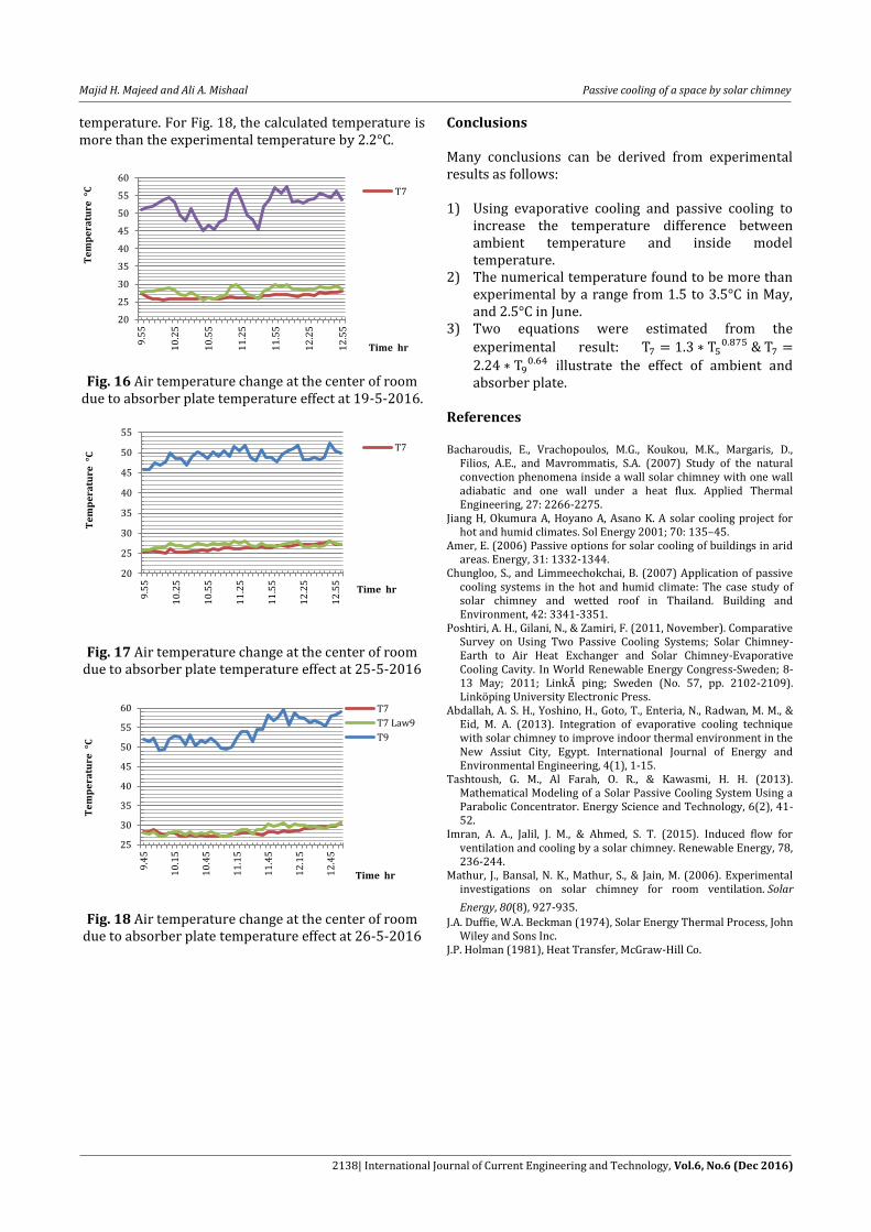
due to ambient effect at 24-5-2016. 5.3 The Relation between the absorber plate temperature and the Temperature of Air at The Center of Room From the experimental reading of the absorber plate temperature and the air temperature at the center of room as shown in the Figures below, it can be concluded a relationship between these temperatures as the following:
(2)
Where: T ir temperature at the center of room. Fig. 16 shows that the calculated temperature from eq. (2) is more than the experimental reading, which was satiable than calculated, but afternoon the temperatures have the same behavior. The maximum difference between the measured and calculated air temperature reach to 3.5°C. In Fig. 17 the difference between the temperatures are less than 2°C and the air temperature behavior at the room center is more stable than the absorber plate
25
30
35
40
10
.00
10
.30
11
.00
11
.30
12
.00
12
.30
Te
mp
era
ture
°C
Time hr
T10 m.
T10 th.
T5
25
30
35
40
10
.00
10
.30
11
.00
11
.30
12
.00
12
.30
Te
mp
era
ture
°C
Time hr
T10 m.
T10 th.
T5
25
30
35
40
10
.00
10
.30
11
.00
11
.30
12
.00
12
.30
Te
mp
era
ture
°C
Time hr
T10 m.
T10 th.
T5
20
25
30
35
40
9.5
5
10
.25
10
.55
11
.25
11
.55
12
.25
12
.55
Te
mp
era
ture
°C
Time hr
T5
20
25
30
35
10
.00
10
.30
11
.00
11
.30
12
.00
12
.30
Te
mp
era
ture
°C
Time hr
T5
Majid H. Majeed and Ali A. Mishaal Passive cooling of a space by solar chimney
2138| International Journal of Current Engineering and Technology, Vol.6, No.6 (Dec 2016)
temperature. For Fig. 18, the calculated temperature is more than the experimental temperature by 2.2°C.
Fig. 16 Air temperature change at the center of room
due to absorber plate temperature effect at 19-5-2016.
Fig. 17 Air temperature change at the center of room due to absorber plate temperature effect at 25-5-2016
Fig. 18 Air temperature change at the center of room
due to absorber plate temperature effect at 26-5-2016
Conclusions Many conclusions can be derived from experimental results as follows: 1) Using evaporative cooling and passive cooling to
increase the temperature difference between ambient temperature and inside model temperature.
2) The numerical temperature found to be more than experimental by a range from 1.5 to 3.5°C in May, and 2.5°C in June.
3) Two equations were estimated from the
experimental result:
illustrate the effect of ambient and
absorber plate. References Bacharoudis, E., Vrachopoulos, M.G., Koukou, M.K., Margaris, D.,
Filios, A.E., and Mavrommatis, S.A. (2007) Study of the natural convection phenomena inside a wall solar chimney with one wall adiabatic and one wall under a heat flux. Applied Thermal Engineering, 27: 2266-2275.
Jiang H, Okumura A, Hoyano A, Asano K. A solar cooling project for hot and humid climates. Sol Energy 2001; 70: 135–45.
Amer, E. (2006) Passive options for solar cooling of buildings in arid areas. Energy, 31: 1332-1344.
Chungloo, S., and Limmeechokchai, B. (2007) Application of passive cooling systems in the hot and humid climate: The case study of solar chimney and wetted roof in Thailand. Building and Environment, 42: 3341-3351.
Poshtiri, A. H., Gilani, N., & Zamiri, F. (2011, November). Comparative Survey on Using Two Passive Cooling Systems; Solar Chimney-Earth to Air Heat Exchanger and Solar Chimney-Evaporative Cooling Cavity. In World Renewable Energy Congress-Sweden; 8-13 May; 2011; Linkà ping; Sweden (No. 57, pp. 2102-2109). Linköping University Electronic Press.
Abdallah, A. S. H., Yoshino, H., Goto, T., Enteria, N., Radwan, M. M., & Eid, M. A. (2013). Integration of evaporative cooling technique with solar chimney to improve indoor thermal environment in the New Assiut City, Egypt. International Journal of Energy and Environmental Engineering, 4(1), 1-15.
Tashtoush, G. M., Al Farah, O. R., & Kawasmi, H. H. (2013). Mathematical Modeling of a Solar Passive Cooling System Using a Parabolic Concentrator. Energy Science and Technology, 6(2), 41-52.
Imran, A. A., Jalil, J. M., & Ahmed, S. T. (2015). Induced flow for ventilation and cooling by a solar chimney. Renewable Energy, 78, 236-244.
Mathur, J., Bansal, N. K., Mathur, S., & Jain, M. (2006). Experimental investigations on solar chimney for room ventilation. Solar
Energy, 80(8), 927-935. J.A. Duffie, W.A. Beckman (1974), Solar Energy Thermal Process, John
Wiley and Sons Inc. J.P. Holman (1981), Heat Transfer, McGraw-Hill Co.
20
25
30
35
40
45
50
55
60
9.5
5
10
.25
10
.55
11
.25
11
.55
12
.25
12
.55
Te
mp
era
ture
°C
Time hr
T7
20
25
30
35
40
45
50
55
9.5
5
10
.25
10
.55
11
.25
11
.55
12
.25
12
.55
Te
mp
era
ture
°C
Time hr
T7
25
30
35
40
45
50
55
60
9.4
5
10
.15
10
.45
11
.15
11
.45
12
.15
12
.45
Te
mp
era
ture
°C
Time hr
T7
T7 Law9
T9