Embed Size (px)
Citation preview
PERFORMANCE ANALYSIS ON MULTIPHASE VOLTAGE SOURCE
INVERTER
Mohd Hafizzudin bin Ismail
Bachelor of Power Electronic and Drives
2012
2
PERFORMANCE ANALYSIS ON MULTIPHASE VOLTAGE SOURCE
INVERTER
MOHD HAFIZZUDIN BIN ISMAIL
A report submitte in partial fulfillment of the requirements for the degree of
Power Electronic and Drives
Faculty of Electrical Engineering
UNIVERSITI TEKNIKAL MALAYSIA MELAKA (UTeM)
JUNE 2012
SUPERVISOR DECLARATION
“I hereby declare that I have read through this report entitle “Performance Analysis On
Multiphase Voltage Source Inverter” and found that it has comply the partial fulfillment for
awarding the degree of Bachelor of Electrical Engineering (Power Electronics and drives)”
Signature : .................................................................................
Supervisor‟s Name : DR AUZANI BIN JIDIN
Date : 26 JUNE 2012

STUDENT DECLARATION
“I declare that this report entitle “Performance Analysis On Multiphase Voltage Source
Inverter” is the result of my own research except as cited in the references. The report has
not been accepted for my any degree and is not concurrently submitted in the candidature
of any other degree”
Signature : .................................................................................
Student‟s Name : MOHD HAFIZZUDIN BIN ISMAIL
Date : 26 JUNE 2012

ii
DEDICATION
Especially dedication is to my beloved mother Puan Hamimah bt Abdul Majid, my beloved
father En Ismail bin Hassan, my sister and brothers beloved
For taking care of me and educating me all these while. Also thank for their continuous
prayers until I became what I‟m now.
Also for my family
Dr Auzani Bin Jidin
Thank you very much
And not forgetting to all my relatives
Especially Electrical Engineering (Power Electronics and Drives) batch 2009-2012
The success belongs to us all
May God bless all of us…..Amin

ii
ACKNOWLEDGEMENT
Assalamualaikum……
First of all, thanks to The Almighty ALLAH S.W.T in giving me extremely
strength to face this final project for this semester. In the process of completing this
project, there are many problems that I have to face in order to achieve the goal of this
project. This makes me closer to the Creator and is testing my patience level. Here, I would
like to thank to all those who have helped me in preparing this report. I wish to thank to
Dr. Auzani b Jidin as a my project coordinator that has helped me a lot to run the project.
I wish to thank my parents who have given me a strength to finish this final report. Once
again, I would grateful to Allah for giving me the strength to complete this project.
iii
ABSTRACT
Application of power electronic in electric drives enables utilization of ac machine
with a phase number higher than three. Such multiphase motor drives are nowadays
considered for various applications. Multiphase inverter is invariably supplied from
multiphase voltage source inverters (VSIs) and adequate method for VSIs pulse width
modulation (PWM) are therefore required. This project deals with sinusoidal pulse width
modulation, which enables an improvement in the DC source utilization as well as power
output. The viability of the proposed concept is proved by simulating taking 5 phase VSI
as an example. Voltage source inverter were implemented using five pairs of IGBT‟s.
Implementation of 5-phase SPWM utilizing Ezdsp F28335 and IQ math component is used
to model the SPWM in Matlab/Simulink. To generate the SPWM, sine waveform and
triangular waveform is needed to get the SPWM. Sine and triangular waveform have their
own frequency 50Hz and 2000Hz respectively.Multiphase inverter can improved the
current ripple and load that connected with the multiphase inverter were run smoothly. In
this experiment, 5-phase voltage source inverter was tested on passive load, resistive-
inductive load.
iv
ABSTRAK
Penggunaan elektronik kuasa dalam pemacu mesin elektrik membolehkan
penggunaan mesin arus ulang alik dengan bilangan fasa yang lebih tinggi daripada tiga.
Pemacu motor berbilang seperti hari ini mula diaplikasikan untuk pelbagai kegunaan.
Voltan pengubah berbilang fasa lazimnya dibekalkan dari penyongsang sumber voltan
berbilang (VSIs) dan kaedah yang digunakan oleh VSIs selalunya dengan menghasilkan
modulasi lebar denyut (PWM). Projek ini mengaplikasikan penggunaan modulasi lebar
denyut sinus untuk mengeluarkan output kepada beban. Daya maju konsep yang
dicadangkan dibuktikan dengan simulasi mengambil 5 fasa VSI sebagai contoh.
Penyongsang sumber voltan telah dilaksanakan menggunakan lima pasang IGBT itu.
Pelaksanaan 5-fasa SPWM menggunakan Ezdsp F28335 dan komponen IQMATH
digunakan untuk memodelkan SPWM di dalam Matlab / Simulink. Untuk menjana
SPWM, gelombang sinus dan gelombang segi tiga diperlukan untuk mendapatkan SPWM.
Gelombang sinus dan gelombang segi tiga masing-masing mempunyai frekuensi 50Hz dan
2000Hz. Pengubah voltan berbilang fasa dapat memperbaiki riak arus keluaran dan beban
yang bersambung dengan penyongsang berbilang dapat berfungsi dengan lancar. Dalam
eksperimen ini, penyongsang sumber voltan 5-fasa telah diuji kepada beban pasif iaitu
beban perintang dan pengaruh.
v
TABLE OF CONTANT
CHAPTER TITLE PAGE
SUPERVISOR DECLARATION
DECLARATION
DEDICATION
ACKNOWLEDGEMENT ii
ABSTRACT iii
ABSTRAK iv
TABLE OF CONTENTS v
LIST OF FIGURE ix
LIST OF TABLE xii
1 INTRODUCTION
1.1 Project Background 1
1.2 Problem Statement 3
1.3 Objective 4
1.4 Scope 4
vi
CHAPTER TITLE PAGE
2 LITERATURE REVIEW
2.1 Introduction 5
2.2 Generalized Sinusoidal PWM With Harmonic Injection 5
For Multi-Phase VSIs
2.3 Modeling Of Multiphase Voltage Source Inverter 6
2.4 Realization Of A Spwm Inverter For Multiphase 7
8 Induction Motor Drive
2.5 Theory Of 3-Phase And 5-Phase System 8
2.6 Sinusoidal Pulse Width Modulation(SPWM) 9
3 METHODOLOGY
3.1 Introduction 11
3.2 Project Methodology 11
3.3 FYP2 Flowchart 13
3.4 Project Phase 14
3.5 Project Development 15
vii
CHAPTER TITLE PAGE
4 DESCRIPTION OF THE EXPERIMENTAL SET-UP
4.1 Introduction 16
4.2 Ezdsp F28335 Digital Signal Processor (DSP)-Board 17
4.3 Altera Complex Programmable Logic Devices (CPLD) 19
4.4 Gate Drivers 21
4.5 Interface Circuit 23
4.6 Voltage Source Inverter 24
5 RESULTS
5.1 Introduction 25
5.2 Simulation Result 25
5.2.1 Spwm Waveform For 3 Phase And 5 Phase 25
Voltage Source Inverter
5.2.2 3 Phases And 5 Phase Voltage Source 26
Inverter In Matlab/Simulink
5.2.3 Generating SPWM In Matlab/Simulink Software 28
5.2.4 Current And Voltage For 3 Phase And 5 Phase 30
VSI
viii
CHAPTER TITLE PAGE
5 5.3 Hardware Results 35
5.3.1 Current Ripple For 3-Phase VSI And 35
5-Phase VSI
5.3.2 Voltage And Current From Different 36
Frequency Of Switching
6 ANALYSIS AND DISCUSSION
6.1 Introduction 40
6.2 Analysis 40
6.3 Discussion 44
7 CONCLUSION AND RECOMMENDATION
7.1 Introduction 45
7.2 Conclusion 45
7.3 Recommendation 46
REFERENCES 47
APPENDICES 49
ix
LIST OF FIGURES
FIGURE TITLE PAGE
2.1 Three Phase System 10
2.2 Five Phase System 10
2.3 Basic Principles Of PWM 12
3.1 Flowchart Of The FYP2 15
3.2 Project Development 18
4.1 Complete Drive System 19
4.2 DS1102 Digital Signal Processor (DSP)-Board 20
4.3 Output Signal From Ezdsp 21
4.4 Altera FPGA 22
4.5 Output Signal From FPGA 23
4.6 Gate Drivers Circuit 24
4.7 Output Signal From Gate Driver Circuit 25
4.8 Interface Circuit 26
4.9 Output Signal From Interface Circuit 26
4.10 Voltage Source Inverter 27
x
FIGURE TITLE PAGE
5.1 3-Phase SPWM 29
5.2 5-Phase SPWM 29
5.3 3-Phase VSI Simulation Block Diagram 29
5.4 5-Phase VSI Simulation Block Diagram 30
5.5 3-Phase Voltage Source Inverter Connection 30
5.6 5-Phase Voltage Source Inverter Connection 31
5.7 Simulation Using IQ-MATH 31
5.8 SPWM For 5-Phase Inverter In Simulation 32
5.9 SPWM For 3-Phase Inverter In Simulation 32
5.10 Phase Voltage For 5-Phase Multiphase Voltage Source Inverter 33
(Voltage Versus Time)
5.11 Phase Voltage For Three Phase Voltage Source Inverter 34
(Voltage Versus Time)
5.12 Total Harmonic Distortion For 3-Phase Voltage 35
5.13 Total Harmonic Distortion For 5-Phase Voltage 35
5.14 Total Harmonic Distortion For 3-Phase Current 36
5.15 Total Harmonic Distortion For 5- Phase Current 37
5.16 3-Phase Current For Hardware 38
5.17 5-Phase Current For Hardware 39
5.18 SPWM For 3-Phase VSI 40
5.19 SPWM For 5-Phase VSI 40
xi
FIGURE TITLE PAGE
5.20 Voltage And Current Output For 2KHz 41
5.21 Voltage And Current Output For 3KHz 41
5.22 Voltage And Current Output For 4KHz 41
6.1 Intersection Point For 3-Phase Inverter 44
6.2 Intersection Point For 5-Phase Inverter 44
6.3 Effect Of PWM To Current Ripple For 3-Phase Inverter 45
6.4 Effect Of PWM To Current Ripple For 5-Phase Inverter 45
6.5 Output Voltage For 3-Phase Inverter 46
6.7 Output Voltage For 5-Phase Inverter 46

xii
LIST OF TABLE
TABLE TITLE PAGE
3.1 Project Planning Of Overall Project Plan For This Project 17
1
CHAPTER 1
INTRODUCTION
1.1 Project Background.
The electric motor is important to our lives. Many machinery uses an electric motor
in it operation no matter on high operation, medium operation and low operation.
Nowadays, many motors use an inverter to convert the DC voltage and enter the inverter to
convert the DC voltage into an AC source and supply to the motor. An inverter, the
switching of the motor is to make the AC motor run with AC source. For this project, the
multilevel voltage source inverter is used to run the motor. From the previous study,
multilevel inverter has many advantages on voltage/current ripple, total harmonic
distortion (THD) and low power dissipation on power switches. The important thing on
multilevel inverter is a the switching scheme. Sinusoidal Pulse Width Modulation (SPWM)
is chosen to make the switching scheme for this multilevel inverter.
The SPWM is created by comparing the sine wave form with the triangular
waveform and the triangular waveform must be higher than the frequency of the sinusoidal
waveform. Many types of industrial fields drive nowadays run a variety task for variety
application, where the difference on speed is needed. Nevertheless, not all of these drives
like a pump and conveyer, require a highly dynamic performance. The main objective of
multiphase inverter static power converters is to produce an AC output waveform from a
DC power supply. These are the types of waveforms required in adjustable speed drives
2
(ASDs), uninterruptible power supplies (UPS), static var compensators, active filters,
flexible AC transmission systems (FACTS), and voltage compensators, which are only a
few applications. For sinusoidal AC outputs, the magnitude, frequency, and phase should
be controllable.
According to the type of ac output waveform, these topologies can be considered as
voltage source inverters (VSIs), where the independently controlled AC output is a voltage
waveform. These structures are the most widely used because they naturally behave as
voltage sources as required by many industrial applications, such as adjustable speed
drives (ASDs), which are the most popular application of inverters. Similarly, these
topologies can be found as current source inverters (CSIs), where the independently
controlled ac output is a current waveform. These structures are still widely used in
medium-voltage industrial applications, where high-quality voltage waveforms are
required. Static power converters, specifically inverters, are constructed from power
switches and the ac output waveforms are therefore made up of discrete values. This leads
to the generation of waveforms that feature fast transitions rather than smooth ones.
For instance, the ac output voltage produced by the VSI of a standard ASD is a
three-level waveform. Although this waveform is not sinusoidal as expected, its
fundamental component behaves as such. This behavior should be ensured by a modulating
technique that controls the amount of time and the sequence used to switch the power
valves on and off. The modulating techniques most used are the carrier-based technique
(e.g. sinusoidal pulse width modulation, SPWM), the space-vector (SV) technique, and the
selective-harmonic-elimination (SHE) technique.
Pulse width modulation with variable speed drives are increasingly applied in many
new industrial applications that require higher performance. Recently, the development of
strength electronics and semiconductor technology have led to the improvement of
electronic energy. Thus, different circuit configurations multilevel inverter have become
popular and it is considerable interest by researcher to find the advantage of the multilevel
3
inverter. Variable number of pulse width modulation systems are used to generate a
variable voltage and frequency.
1.2 Problem Statement.
Many types of inverter nowadays only changing the DC source to a 3 phase system
and to the load. In this project, dc source will be converted into five phase AC source and
supply to the load. In this modern world, many researchers make a researcher on making a
new inverter like a multiphase source inverter using the additional phase like a 5 phase
voltage source inverter. If the motor runs with 3 phase source, it becomes normal but if 1
of the 3 phase supply broken, motor will run with unbalance load. After a few times the
motor will trip because the motor overheating. Researcher gets an idea to make a
multiphase voltage source inverter to run an induction motor because when motor using
multiphase voltage source inverter, the motor also can run if 1 phase of the source broken.
In this project, the 5 phase RL load will drive with 5 phase voltage source inverter. It will
show what will effect to the load voltage and current when increasing the phase to the load
and voltage source inverter.
Multi-phase (more than 3 phase) drives possess several advantages over
conventional three-phase drives such as reducing the amplitude and increasing the
frequency of torque pulsations, reducing the rotor harmonic currents, reducing the current
per phase without increasing the voltage per phase, lowering the dc link current harmonics
and higher reliability. By increasing the number of phases it is also possible to increase the
power/torque per RMS ampere for the same volume machine. Today‟s world, many kinds
of motor use 1 inverter to control the behavior of the motor but with multiphase voltage
source inverter, we can run two same types of induction motor with parallel connection by
control only one of the motor. The behavior of the two motors is same in term of speed and
torque. It can save money by reducing the inverter construction.

4
1.3 Objective
The main objective of the project is
1) To analyze the performance of multilevel inverter in term of current ripple and total
harmonic distortion (THD).
2) To construct the switching scheme of the multiphase inverter using a
Matlab/Simulink and Ezdsp.
1.4 Scope
In order to achieve this objective, several scopes had been outlined.
i. Matlab/Simulink software and Ezdsp software will be performed on
computer and also Ezdsp platform device is used.
ii. The switching sinusoidal pulse width modulation (SPWM) for the multiphase
inverter were programed in Matlab/Simulink software.
iii. The difference between 3 phase and multiphase inverter were simulated in
Matlab/Simulink.
iv. The performance of 5-phase SPWM for balanced passive loads like a
resistive-inductive load will be analyzed to highlight the advantages of
multiphase system.
5
CHAPTER 2
LITERATURE REVIEW
2.1 Introduction
This chapter will discuss overall of the previous research about this project and
what is the opinion from previous research can use for this project. In this chapter also will
discuss about the theory of 3 phase and 5 phase system.
2.2 Generalized Sinusoidal PWM With Harmonic Injection For Multi-Phase Vsis
Many kinds of machine that use motor have a variable speed and that machine
almost all use three phase machine. When a power electronics is occurred on controlling
the VSI, the 3 legs of phase cannot be a suitable phase to running a load. Converter has
make a different in term of control a motor‟s speed and converter was proven can give a lot
of advantage on motor controller. Nowadays, many researcher making a research on how
to get the suitable switching for a multiphase voltage source inverter [1]. Many kind of
PWM available on controlling the gate switching. The most popular switching PWM for a
voltage source inverter are sinusoidal pulse width modulation (SPWM) and space vector
modulation (SVPWM). This two technique will discussed in literature. There have a lot of
way to control the switching using multiphase voltage source inverter. That is happen
because too many vector can be controlled in electrical system and this make a lot of
6
research based on motor controller. In space vector modulation, the voltage reference is a
most important because that kind of reference is use to make decision on vector choosing.
Multiphase voltage source inverter also have a problem when running a motor and that is
called low order voltage harmonic, this kind of harmonic will make the stator current
harmonic increase [1].
That is why the switching for multiphase inverter always different and keep on
researching. When a multiphase inverter supplied with a sinusoidal PWM switching, we
must mind that the output of the voltage source inverter do not have a low order stator
harmonic [1]. The sinusoidal pulse width modulation and space vector modulation become
a famous technique on control the speed of ac motor.
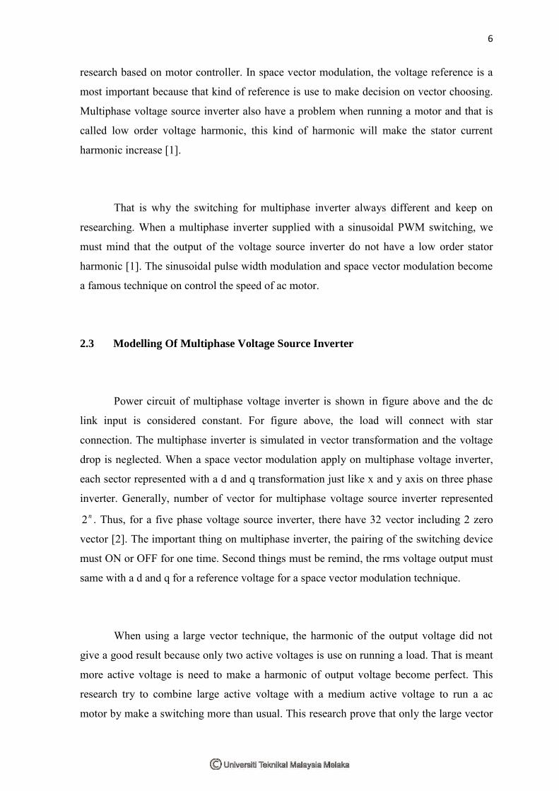
2.3 Modelling Of Multiphase Voltage Source Inverter
Power circuit of multiphase voltage inverter is shown in figure above and the dc
link input is considered constant. For figure above, the load will connect with star
connection. The multiphase inverter is simulated in vector transformation and the voltage
drop is neglected. When a space vector modulation apply on multiphase voltage inverter,
each sector represented with a d and q transformation just like x and y axis on three phase
inverter. Generally, number of vector for multiphase voltage source inverter represented n2 . Thus, for a five phase voltage source inverter, there have 32 vector including 2 zero
vector [2]. The important thing on multiphase inverter, the pairing of the switching device
must ON or OFF for one time. Second things must be remind, the rms voltage output must
same with a d and q for a reference voltage for a space vector modulation technique.
When using a large vector technique, the harmonic of the output voltage did not
give a good result because only two active voltages is use on running a load. That is meant
more active voltage is need to make a harmonic of output voltage become perfect. This
research try to combine large active voltage with a medium active voltage to run a ac
motor by make a switching more than usual. This research prove that only the large vector
7
make a high on harmonic on output voltage for multiphase voltage inverter [2]. So, this
two technique is apply to make the output voltage of voltage source inverter similarly like
a sinusoidal in addition to make a switching scheme for a multiphase voltage source
inverter. However, output voltage of voltage source inverter cannot be produce 100%
because the switching of gate make a losses for the system.
2.4 Realization Of A Spwm Inverter For Multiphase Induction Motor Drive
Conventional three phase motor usually use a three phase source from a three phase
voltage source inverter. Development on many type of power converter make a new idea to
develop a converter that have more than three phase. Example of advantage of multiphase
power converter is a produce a high voltage from a low DC source. For a decade
researching is make to settle a problem that occurred in high voltage application. For a
multiphase inverter, there a many type of switching technique can be apply for an example
sinusoidal pulse width modulation and space vector modulation. The objective for all
studied on multiphase voltage inverter is to generate a output voltage of inverter similarly
sinusoidal wave and increasing the performance on total harmonic distortion (THD).
Today, the multiphase inverter become more popular when the inverter come out with
many advantage on performance of the load that the inverter drive [3]. The multiphase
voltage source inverter have 25% improvement on produce a sinusoidal output voltage [3].
For 3 phase inverter drive, the space vector is a popular technique, but when space vector
and sine PWM applied on multiphase inverter, the result almost same on all parameter like
a voltage output, total harmonic distortion.
For a multiphase inverter in this paper, sine pwm is choose to drive a motor.
Sinusoidal pulse width modulation is more easy to simulate better than a space vector
modulation. The performance of the load is nearly same when this two technique was
applied. That is the reason why the SPWM technique is choose but researcher continue
their research on space vector because the space vector is more efficient on controlling the
motor speed. For nine phase voltage source inverter, space vector must have 51229
space of vector on 360 plane [3]. This type of technique is not practical for a multiphase
8
voltage source inverter. For a 360 plane, 512 of vector becomes a problem on divide a
degree for each vector [3]. Many problem will occurred when space vector applied on
multiphase voltage source inverter especially on complexity of space vector algorithm.
When a inverter changing on phase, the old space vector algorithm cannot be use and new
algorithm must create. For SPWM, the switching algorithm cannot be a problem when the
inverter phase is changing. The original algorithm can be use when a inverter phase is
changing [3]. SPWM technique is most easy technique to generate a PWM.
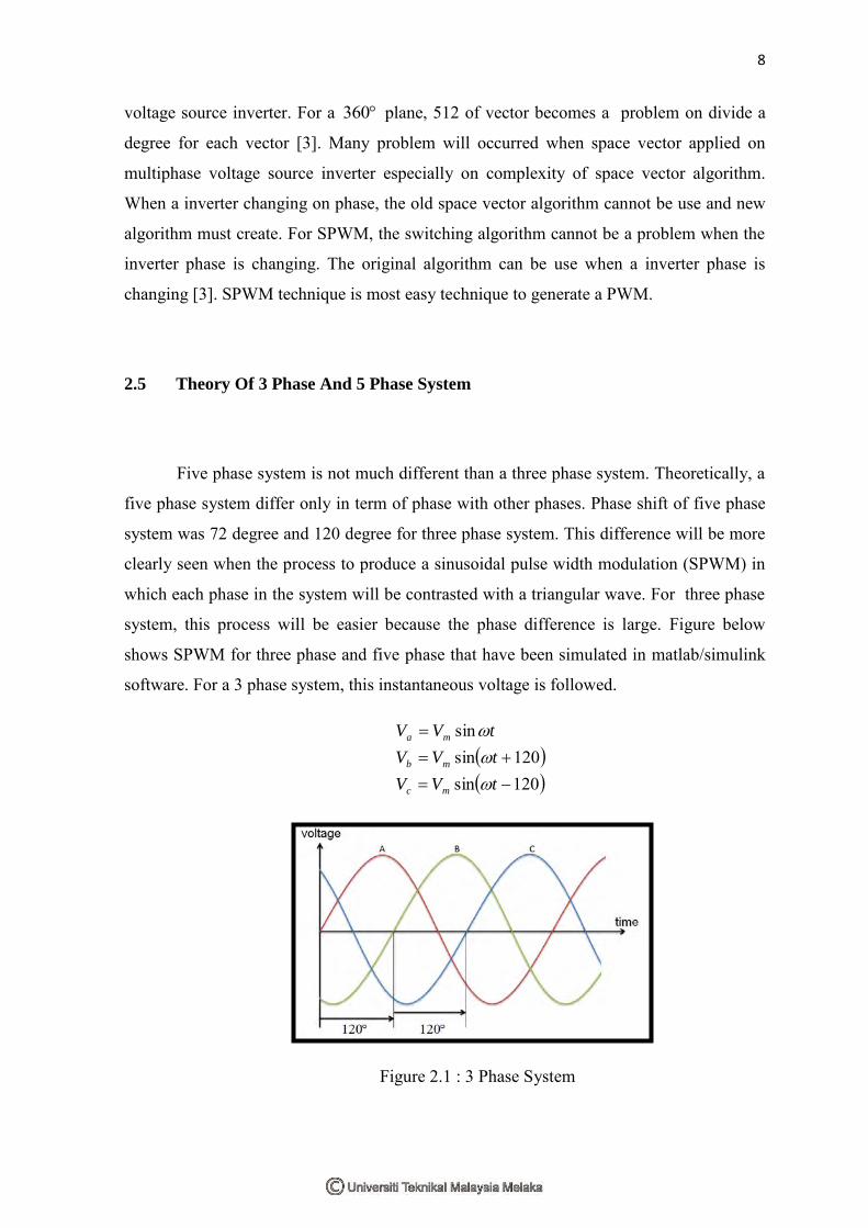
2.5 Theory Of 3 Phase And 5 Phase System
Five phase system is not much different than a three phase system. Theoretically, a
five phase system differ only in term of phase with other phases. Phase shift of five phase
system was 72 degree and 120 degree for three phase system. This difference will be more
clearly seen when the process to produce a sinusoidal pulse width modulation (SPWM) in
which each phase in the system will be contrasted with a triangular wave. For three phase
system, this process will be easier because the phase difference is large. Figure below
shows SPWM for three phase and five phase that have been simulated in matlab/simulink
software. For a 3 phase system, this instantaneous voltage is followed.
120sin120sin
sin
tVV
tVV
tVV
mc
mb
ma
Figure 2.1 : 3 Phase System


![SVM Strategies for Multiphase Voltage Source Inverters · 2 1 2 n k «» «» ¬¼ (1) Clarke’s decoupling transformation matrix [2] for a multiphase system with an arbitrary phase](https://img.pdfslide.us/doc/110x75/5be659dd09d3f2c44d8d9812/svm-strategies-for-multiphase-voltage-source-inverters-2-1-2-n-k-.jpg)

![K101 DC Voltage Measurements.pptx [Read-Only] DC Voltage... · Voltage Measurements V Source of Voltage V s Voltmeter Two main problems: 1. Source is not ideal, V sis dependent upon](https://img.pdfslide.us/doc/110x75/5af680197f8b9a8d1c8efdcc/k101-dc-voltage-read-only-dc-voltagevoltage-measurements-v-source-of-voltage.jpg)