Embed Size (px)
Citation preview
International Journal of Scientific & Engineering Research Volume 10, Issue 4, April-2019 555 ISSN 2229-5518
IJSER © 2019 http://www.ijser.org
Performance Analysis of Control Channel in LTE
By
Imran Rafiq Institute of Communication Technologies (ICT)
[email protected] Abstract Main purpose of LTE Network is to provide higher average throughput for both uplink and downlinks. The performance of LTE Network is dependent on efficient utilization of resources. Control channels play a key role in enhancing the throughput high gains. This research work is mainly focused on the downlink control channels which are analyzed to minimize their impact on the LTE system performance. The simulation is done by setting certain parameters on LTE-Sim simulator and throughput gains are measured using a scheduler. Introduction 1.1. Introduction to the topic Research of LTE (Long Term Evolution advanced) Network has great importance in the present epoch due to increase in mobile subscribers’ demand. Orthogonal frequency division multiple access (OFDMA) is utilized for LTE downlink direction and SC-FDMA (single carrier frequency division multiple access) is utilized for uplink direction [1]. These technologies of multiple access provide enhancement in performance and high gains in frequency scheduling for multiple users. Dynamic FDPS (Frequency domain packet scheduling) provide these gains [11]. Packet scheduling has given diversity gains due to increasing control signaling overhead. To optimize the packet scheduling decisions, each user equipment
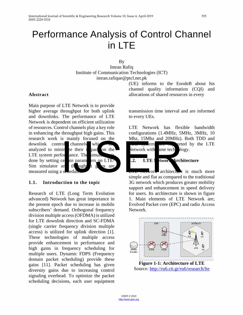
(UE) informs to the EnodeB about his channel quality information (CQI) and allocations of shared resources in every transmission time interval and are informed to every UEs. LTE Network has flexible bandwidth configurations (1.4MHz, 5MHz, 3MHz, 10 Mhz, 15Mhz and 20MHz). Both TDD and FDD systems are supported by the LTE Network with same technology. 1.2. LTE Network Architecture LTE Network architecture is much more simple and flat as compared to the traditional 3G network which produces greater mobility support and enhancement in speed delivery for users. Its architecture is shown in figure 1. Main elements of LTE Network are; Evolved Packet core (EPC) and radio Access Network.
Figure 1-1: Architecture of LTE
Source: http://ru6.cti.gr/ru6/research/lte
IJSER
International Journal of Scientific & Engineering Research Volume 10, Issue 4, April-2019 556 ISSN 2229-5518
IJSER © 2019 http://www.ijser.org
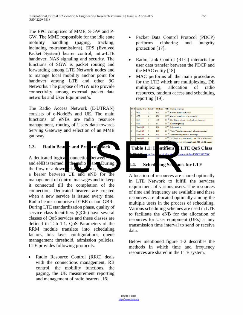
The EPC comprises of MME, S-GW and P-GW. The MME responsible for the idle state mobility handling (paging, tracking, including re-transmissions), EPS (Evolved Packet System) bearer control, intra-LTE handover, NAS signaling and security. The functions of SGW is packet routing and forwarding among LTE Network nodes and to manage local mobility anchor point for handover among LTE and other 3G Networks. The purpose of PGW is to provide connectivity among external packet data networks and User Equipment’s. The Radio Access Network (E-UTRAN) consists of e-NodeBs and UE. The main functions of eNBs are radio resource management, routing of Users data towards Serving Gateway and selection of an MME gateway. 1.3. Radio Bearer and Protocol Stack A dedicated logical connection between UE and eNB is termed as the radio bearer. During the flow of a downlink and uplink, it creates a bearer between UE and eNB for the management of control massages and to keep it connected till the completion of the connection. Dedicated bearers are created when a new service is issued every time. Radio bearer comprise of GBR or non GBR. During LTE standardization phase, quality of service class Identifiers (QCIs) have several classes of QoS services and these classes are defined in Tab 1.1. QoS Parameters of the RRM module translate into scheduling factors, link layer configurations, queue management threshold, admission policies. LTE provides following protocols. • Radio Resource Control (RRC) deals
with the connections management, RB control, the mobility functions, the paging, the UE measurement reporting and management of radio bearers [16].
• Packet Data Control Protocol (PDCP)
performs ciphering and integrity protection [17].
• Radio Link Control (RLC) interacts for
user data transfer between the PDCP and the MAC entity [18]
• MAC performs all the main procedures for the LTE which are multiplexing, DE multiplexing, allocation of radio resources, random access and scheduling reporting [19].
Table 1.1: Identifiers of LTE QoS Class
Source: https://www.ncbi.nlm.nih.gov/pmc/articles/PMC6347206/
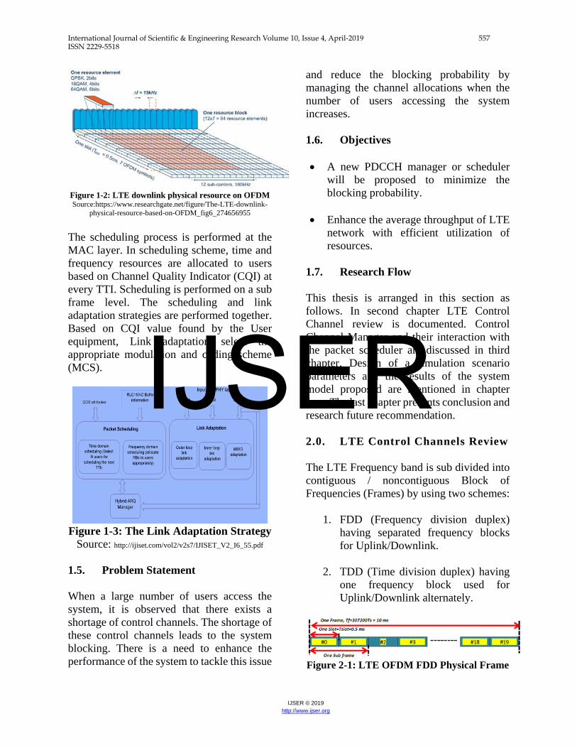
1.4. Scheduling Schemes for LTE Allocation of resources are shared optimally in LTE Network to fulfill the services requirement of various users. The resources of time and frequency are available and these resources are allocated optimally among the multiple users in the process of scheduling. Various scheduling schemes are used in LTE to facilitate the eNB for the allocation of resources for User equipment (UEs) at any transmission time interval to send or receive data. Below mentioned figure 1-2 describes the methods in which time and frequency resources are shared in the LTE system.
IJSER
International Journal of Scientific & Engineering Research Volume 10, Issue 4, April-2019 557 ISSN 2229-5518
IJSER © 2019 http://www.ijser.org
Figure 1-2: LTE downlink physical resource on OFDM Source:https://www.researchgate.net/figure/The-LTE-downlink-
physical-resource-based-on-OFDM_fig6_274656955
The scheduling process is performed at the MAC layer. In scheduling scheme, time and frequency resources are allocated to users based on Channel Quality Indicator (CQI) at every TTI. Scheduling is performed on a sub frame level. The scheduling and link adaptation strategies are performed together. Based on CQI value found by the User equipment, Link adaptation select the appropriate modulation and coding scheme (MCS).
Figure 1-3: The Link Adaptation Strategy
Source: http://ijiset.com/vol2/v2s7/IJISET_V2_I6_55.pdf 1.5. Problem Statement When a large number of users access the system, it is observed that there exists a shortage of control channels. The shortage of these control channels leads to the system blocking. There is a need to enhance the performance of the system to tackle this issue
and reduce the blocking probability by managing the channel allocations when the number of users accessing the system increases. 1.6. Objectives
• A new PDCCH manager or scheduler
will be proposed to minimize the blocking probability.
• Enhance the average throughput of LTE network with efficient utilization of resources.
1.7. Research Flow This thesis is arranged in this section as follows. In second chapter LTE Control Channel review is documented. Control Channel Manager and their interaction with the packet scheduler are discussed in third chapter. Design of a simulation scenario parameters and the results of the system model proposed are mentioned in chapter four. The last chapter presents conclusion and research future recommendation. 2.0. LTE Control Channels Review The LTE Frequency band is sub divided into contiguous / noncontiguous Block of Frequencies (Frames) by using two schemes:
1. FDD (Frequency division duplex) having separated frequency blocks for Uplink/Downlink.
2. TDD (Time division duplex) having one frequency block used for Uplink/Downlink alternately.
Figure 2-1: LTE OFDM FDD Physical Frame
IJSER
International Journal of Scientific & Engineering Research Volume 10, Issue 4, April-2019 558 ISSN 2229-5518
IJSER © 2019 http://www.ijser.org
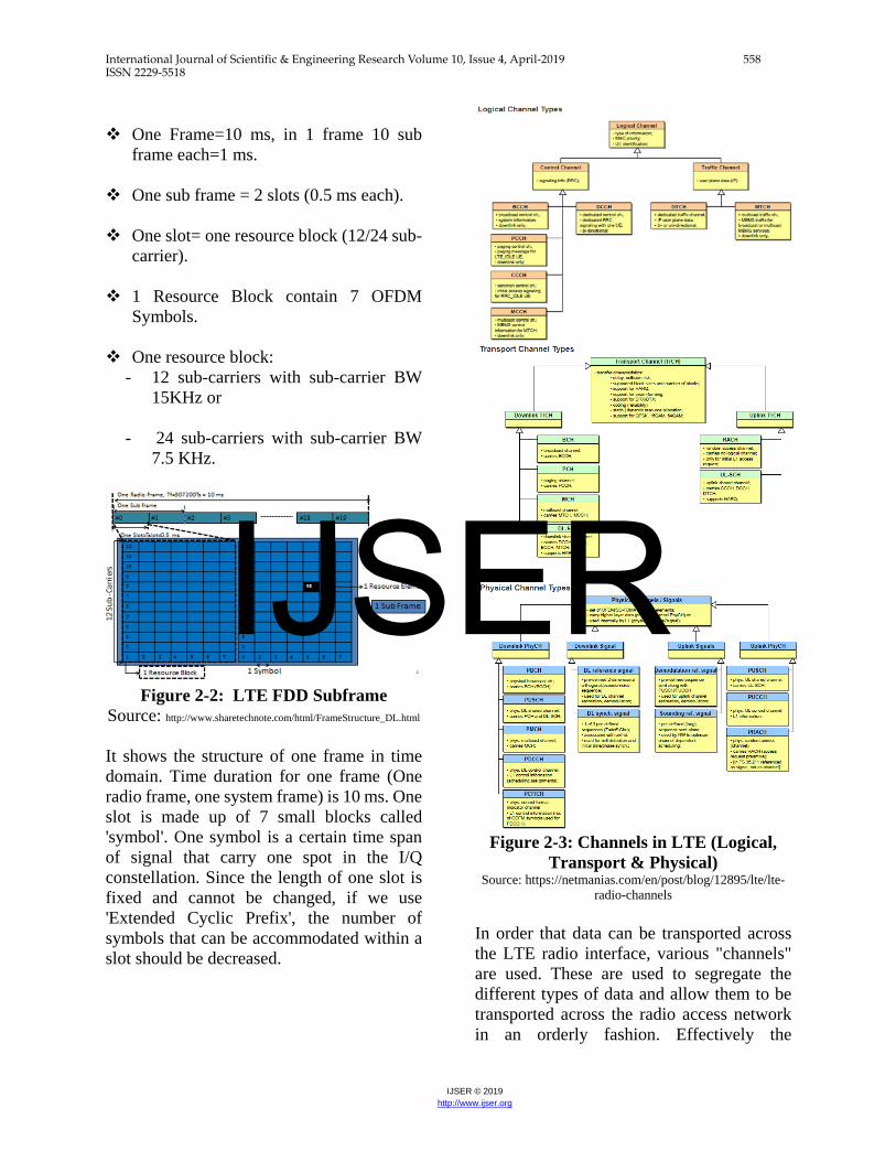
One Frame=10 ms, in 1 frame 10 sub
frame each=1 ms.
One sub frame = 2 slots (0.5 ms each). One slot= one resource block (12/24 sub-
carrier). 1 Resource Block contain 7 OFDM
Symbols. One resource block:
- 12 sub-carriers with sub-carrier BW 15KHz or
- 24 sub-carriers with sub-carrier BW 7.5 KHz.
Figure 2-2: LTE FDD Subframe
Source: http://www.sharetechnote.com/html/FrameStructure_DL.html
It shows the structure of one frame in time domain. Time duration for one frame (One radio frame, one system frame) is 10 ms. One slot is made up of 7 small blocks called 'symbol'. One symbol is a certain time span of signal that carry one spot in the I/Q constellation. Since the length of one slot is fixed and cannot be changed, if we use 'Extended Cyclic Prefix', the number of symbols that can be accommodated within a slot should be decreased.
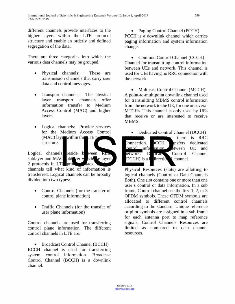
Figure 2-3: Channels in LTE (Logical,
Transport & Physical) Source: https://netmanias.com/en/post/blog/12895/lte/lte-
radio-channels
In order that data can be transported across the LTE radio interface, various "channels" are used. These are used to segregate the different types of data and allow them to be transported across the radio access network in an orderly fashion. Effectively the
IJSER
International Journal of Scientific & Engineering Research Volume 10, Issue 4, April-2019 559 ISSN 2229-5518
IJSER © 2019 http://www.ijser.org
different channels provide interfaces to the higher layers within the LTE protocol structure and enable an orderly and defined segregation of the data. There are three categories into which the various data channels may be grouped.
• Physical channels: These are transmission channels that carry user data and control messages.
• Transport channels: The physical layer transport channels offer information transfer to Medium Access Control (MAC) and higher layers.
• Logical channels: Provide services for the Medium Access Control (MAC) layer within the LTE protocol structure.
Logical channels reside between RLC sublayer and MAC sublayer which are layer 2 protocols in LTE protocol stack. Logical channels tell what kind of information is transferred. Logical channels can be broadly divided into two types:
• Control Channels (for the transfer of control plane information)
• Traffic Channels (for the transfer of user plane information)
Control channels are used for transferring control plane information. The different control channels in LTE are:
• Broadcast Control Channel (BCCH) BCCH channel is used for transferring system control information. Broadcast Control Channel (BCCH) is a downlink channel.
• Paging Control Channel (PCCH) PCCH is a downlink channel which carries paging information and system information change.
• Common Control Channel (CCCH) Channel for transmitting control information between UEs and network. This channel is used for UEs having no RRC connection with the network.
• Multicast Control Channel (MCCH) A point-to-multipoint downlink channel used for transmitting MBMS control information from the network to the UE, for one or several MTCHs. This channel is only used by UEs that receive or are interested to receive MBMS.
• Dedicated Control Channel (DCCH) DCCH is used when there is RRC Connection. DCCH transfers dedicated control information between UE and network. Dedicated Control Channel (DCCH) is a bidirectional channel. Physical Resources (slots) are allotting to logical channels (Control or Data Channels Both). One slot contains one or more than one user’s control or data information. In a sub frame, Control channel use the first 1, 2, or 3 OFDM symbols. These OFDM symbols are allocated to different control channels according to the standard. Unique reference or pilot symbols are assigned in a sub frame for each antenna port to map reference signals. Control Channels Resources are limited as compared to data channel resources.
IJSER
International Journal of Scientific & Engineering Research Volume 10, Issue 4, April-2019 560 ISSN 2229-5518
IJSER © 2019 http://www.ijser.org
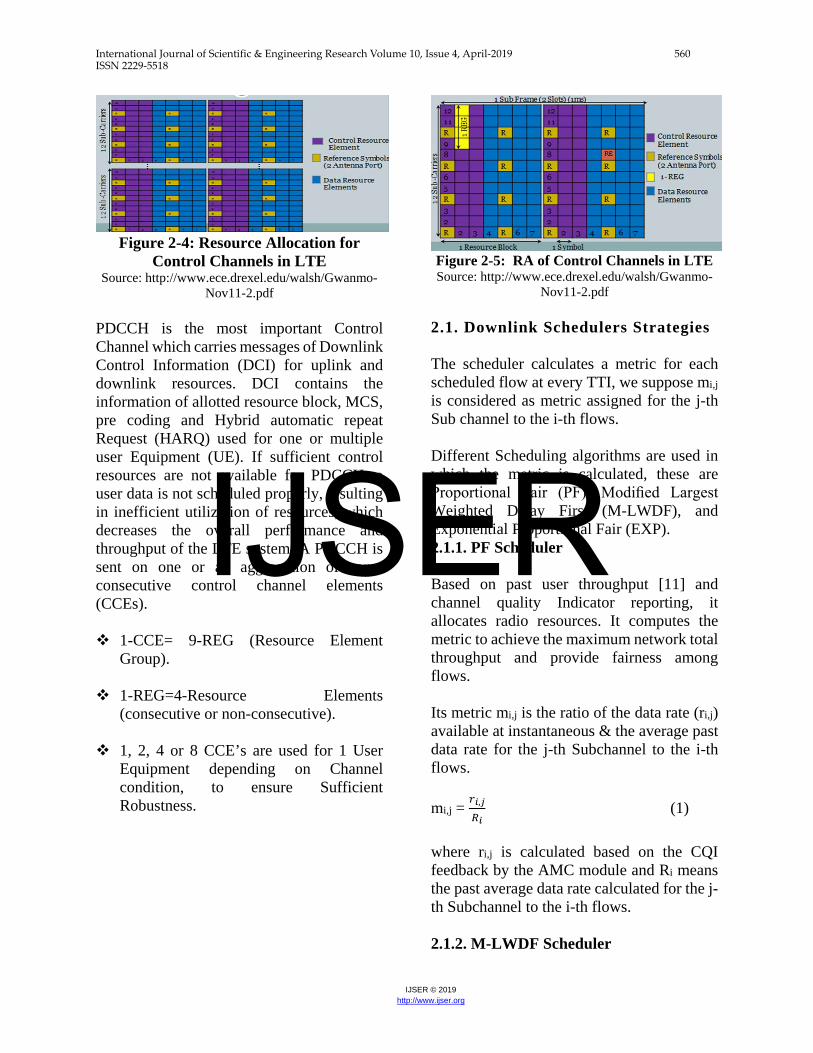
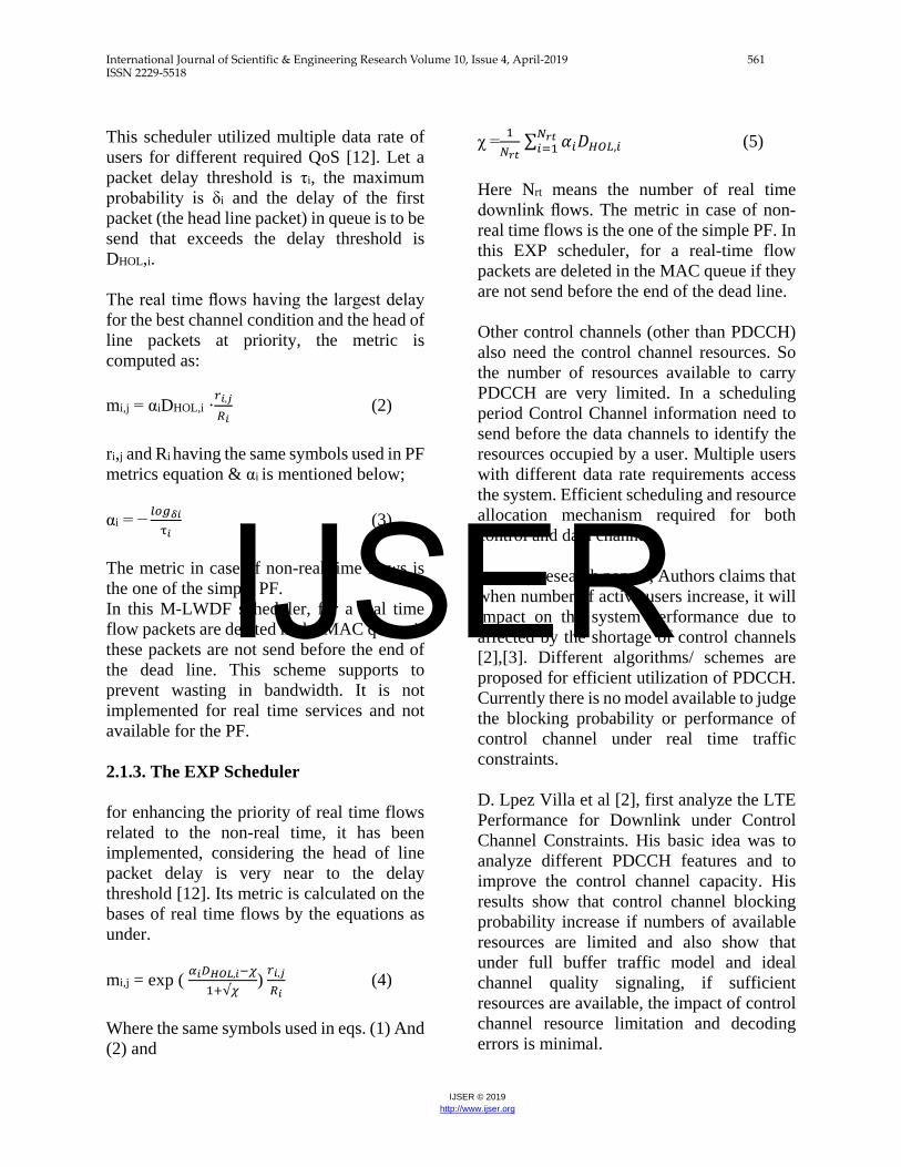
Figure 2-4: Resource Allocation for
Control Channels in LTE Source: http://www.ece.drexel.edu/walsh/Gwanmo-
Nov11-2.pdf PDCCH is the most important Control Channel which carries messages of Downlink Control Information (DCI) for uplink and downlink resources. DCI contains the information of allotted resource block, MCS, pre coding and Hybrid automatic repeat Request (HARQ) used for one or multiple user Equipment (UE). If sufficient control resources are not available for PDCCH, a user data is not scheduled properly, resulting in inefficient utilization of resources, which decreases the overall performance and throughput of the LTE system. A PDCCH is sent on one or an aggregation of some consecutive control channel elements (CCEs). 1-CCE= 9-REG (Resource Element
Group).
1-REG=4-Resource Elements (consecutive or non-consecutive).
1, 2, 4 or 8 CCE’s are used for 1 User
Equipment depending on Channel condition, to ensure Sufficient Robustness.
Figure 2-5: RA of Control Channels in LTE Source: http://www.ece.drexel.edu/walsh/Gwanmo-
Nov11-2.pdf 2.1. Downlink Schedulers Strategies The scheduler calculates a metric for each scheduled flow at every TTI, we suppose mi,j
is considered as metric assigned for the j-th Sub channel to the i-th flows. Different Scheduling algorithms are used in which the metric is calculated, these are Proportional Fair (PF), Modified Largest Weighted Delay First (M-LWDF), and Exponential Proportional Fair (EXP). 2.1.1. PF Scheduler Based on past user throughput [11] and channel quality Indicator reporting, it allocates radio resources. It computes the metric to achieve the maximum network total throughput and provide fairness among flows. Its metric mi,j is the ratio of the data rate (ri,j) available at instantaneous & the average past data rate for the j-th Subchannel to the i-th flows. mi,j = 𝑟𝑟𝑖𝑖,𝑗𝑗
𝑅𝑅𝑖𝑖 (1)
where ri,j is calculated based on the CQI feedback by the AMC module and Ri means the past average data rate calculated for the j-th Subchannel to the i-th flows. 2.1.2. M-LWDF Scheduler
IJSER
International Journal of Scientific & Engineering Research Volume 10, Issue 4, April-2019 561 ISSN 2229-5518
IJSER © 2019 http://www.ijser.org
This scheduler utilized multiple data rate of users for different required QoS [12]. Let a packet delay threshold is τi, the maximum probability is δi and the delay of the first packet (the head line packet) in queue is to be send that exceeds the delay threshold is DHOL,i. The real time flows having the largest delay for the best channel condition and the head of line packets at priority, the metric is computed as: mi,j = αiDHOL,i ·
𝑟𝑟𝑖𝑖,𝑗𝑗𝑅𝑅𝑖𝑖
(2) ri,j and Ri having the same symbols used in PF metrics equation & αi is mentioned below; αi = −
𝑙𝑙𝑙𝑙𝑙𝑙𝛿𝛿𝑖𝑖τ𝑖𝑖
(3) The metric in case of non-real time flows is the one of the simple PF. In this M-LWDF scheduler, for a real time flow packets are deleted in the MAC queue if these packets are not send before the end of the dead line. This scheme supports to prevent wasting in bandwidth. It is not implemented for real time services and not available for the PF. 2.1.3. The EXP Scheduler for enhancing the priority of real time flows related to the non-real time, it has been implemented, considering the head of line packet delay is very near to the delay threshold [12]. Its metric is calculated on the bases of real time flows by the equations as under. mi,j = exp ( 𝛼𝛼𝑖𝑖𝐷𝐷𝐻𝐻𝐻𝐻𝐻𝐻,𝑖𝑖−𝜒𝜒
1+√𝜒𝜒) 𝑟𝑟𝑖𝑖,𝑗𝑗𝑅𝑅𝑖𝑖
(4) Where the same symbols used in eqs. (1) And (2) and
χ = 1
𝑁𝑁𝑟𝑟𝑟𝑟 ∑ 𝛼𝛼𝑖𝑖𝐷𝐷𝐻𝐻𝐻𝐻𝐻𝐻,𝑖𝑖
𝑁𝑁𝑟𝑟𝑟𝑟𝑖𝑖=1 (5)
Here Nrt means the number of real time downlink flows. The metric in case of non-real time flows is the one of the simple PF. In this EXP scheduler, for a real-time flow packets are deleted in the MAC queue if they are not send before the end of the dead line. Other control channels (other than PDCCH) also need the control channel resources. So the number of resources available to carry PDCCH are very limited. In a scheduling period Control Channel information need to send before the data channels to identify the resources occupied by a user. Multiple users with different data rate requirements access the system. Efficient scheduling and resource allocation mechanism required for both control and data channels. In many research papers, Authors claims that when number of active users increase, it will impact on the system performance due to affected by the shortage of control channels [2],[3]. Different algorithms/ schemes are proposed for efficient utilization of PDCCH. Currently there is no model available to judge the blocking probability or performance of control channel under real time traffic constraints. D. Lpez Villa et al [2], first analyze the LTE Performance for Downlink under Control Channel Constraints. His basic idea was to analyze different PDCCH features and to improve the control channel capacity. His results show that control channel blocking probability increase if numbers of available resources are limited and also show that under full buffer traffic model and ideal channel quality signaling, if sufficient resources are available, the impact of control channel resource limitation and decoding errors is minimal.
IJSER
International Journal of Scientific & Engineering Research Volume 10, Issue 4, April-2019 562 ISSN 2229-5518
IJSER © 2019 http://www.ijser.org
Authors don’t have considered the realistic PDCCH constraints like (decoding constraints, and for data channel allocation PDCCH-related packet scheduling limitations). Francesco Capozzi et al [4], enhance the work of D.Lo´pez et al. [2], and describe a Modified PDCCH modeling system. He introduced the idea of PDCCH Manager Required and the performance of a LTE downlink Network system is measured with realistic PDCCH resource constraints and packet scheduling limitations for the allocation of data channels. Simulation results shows that due to the PDCCH decoding constraints, when the time domain packet scheduling (TDPS) select a large number of users, the PDCCH Manager blocked the increase in actual number of users however more user’s data is scheduled [5]. Francesco Capozzi et al. [4] gave a more realistic PDCCH Scheduling scheme but they have not described the blocking probability of control channels. Based on the work proposed by D.Lo´pez et al [2] and Francesco Capozzi et al [4]. To enhance the system performance, Researchers [6], [7] proposed different Algorithm for efficient utilization of PDCCH. Li Li et al [6] describe that the main purpose of allocation of PDCCH resource is to efficiently pack the large no. of users into limited amount of control channels resources. Li Li et al proposed an algorithm based on aggregation level named as minimum aggregation level algorithm (Min-AL). Min-AL maximize the no. of scheduled users through utilizing multi-user diversity gain and concluded that Min-AL algorithm produces the efficient system performance of Network at the cell edge position. Authors of [8-10] also address the issue of efficient utilization of PDCCH by proposing different Algorithms and compare them with
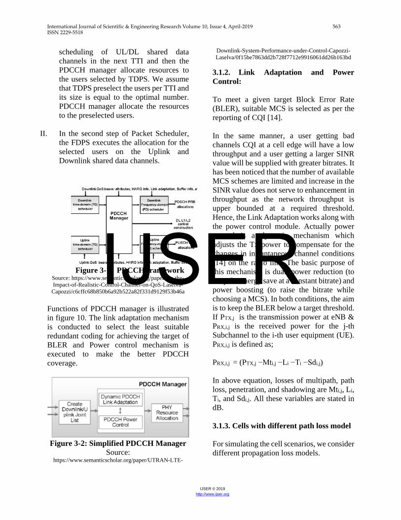
existing algorithms but the main issue is that no paper describe how many PDCCH resources allot to avoid blocking. 3.0. Control Channel Manager interactions with packet Scheduler 3.1. PDCCH PDCCH contains the information of resource allocation of each uplink/down scheduled user on the uplink and downlink data channel. The smallest part of time/frequency resource is Resource Element (RE). It contains one OFDM symbols in time and one subcarrier in frequency. Amount of REs available for PDCCH is limited and it is around 4/5 REs for downlink channels depending on available total bandwidth B and it can be expressed as; NRE = Nsy . B / ∆ Where Nsy shows the No. of OFDM symbols allocated for control channels and ∆ means the subcarrier space [13]. As the resources are limited to downlink control channel and it require the resource management for PDCCH is called PDCCH manager. Its basic function is to allocate maximum resources during the schedule users per TTI for reducing the wastage of data channel resources and PDCCH Block error rate (BLER). 3.1.1. PDCCH Manager interactions with packet scheduler PDCCH manager works with dynamic packet scheduler for UL/DL data channel while exact implementation depends upon vendor specific. Packet scheduler operates in two steps.
I. Time domain packet scheduler (TDPS) selects the priority base list of users for
IJSER
International Journal of Scientific & Engineering Research Volume 10, Issue 4, April-2019 563 ISSN 2229-5518
IJSER © 2019 http://www.ijser.org
scheduling of UL/DL shared data channels in the next TTI and then the PDCCH manager allocate resources to the users selected by TDPS. We assume that TDPS preselect the users per TTI and its size is equal to the optimal number. PDCCH manager allocate the resources to the preselected users.
II. In the second step of Packet Scheduler, the FDPS executes the allocation for the selected users on the Uplink and Downlink shared data channels.
Figure 3-1: PDCCH framework
Source: https://www.semanticscholar.org/paper/On-the-Impact-of-Realistic-Control-Channel-on-QoS-Laselva-
Capozzi/c6cffc68b850b6a92b522a82f331d9129f53b46a Functions of PDCCH manager is illustrated in figure 10. The link adaptation mechanism is conducted to select the least suitable redundant coding for achieving the target of BLER and Power control mechanism is executed to make the better PDCCH coverage.
Figure 3-2: Simplified PDCCH Manager
Source: https://www.semanticscholar.org/paper/UTRAN-LTE-
Downlink-System-Performance-under-Control-Capozzi-Laselva/0f15be7863dd2b728f7712e9916061dd26b163bd
3.1.2. Link Adaptation and Power Control: To meet a given target Block Error Rate (BLER), suitable MCS is selected as per the reporting of CQI [14]. In the same manner, a user getting bad channels CQI at a cell edge will have a low throughput and a user getting a larger SINR value will be supplied with greater bitrates. It has been noticed that the number of available MCS schemes are limited and increase in the SINR value does not serve to enhancement in throughput as the network throughput is upper bounded at a required threshold. Hence, the Link Adaptation works along with the power control module. Actually power control is a dynamic mechanism which adjusts the Tx power to compensate for the changes in instantaneous channel conditions [14] on the radio link. The basic purpose of this mechanism is dual: power reduction (to keep the energy save at a constant bitrate) and power boosting (to raise the bitrate while choosing a MCS). In both conditions, the aim is to keep the BLER below a target threshold. If PTX,j is the transmission power at eNB & PRX,i,j is the received power for the j-th Subchannel to the i-th user equipment (UE). PRX,i,j is defined as; PRX,i,j = (PTX,j −Mti,j −Li −Ti −Sdi,j) In above equation, losses of multipath, path loss, penetration, and shadowing are Mti,j, Li, Ti, and Sdi,j. All these variables are stated in dB. 3.1.3. Cells with different path loss model For simulating the cell scenarios, we consider different propagation loss models.
IJSER
International Journal of Scientific & Engineering Research Volume 10, Issue 4, April-2019 564 ISSN 2229-5518
IJSER © 2019 http://www.ijser.org
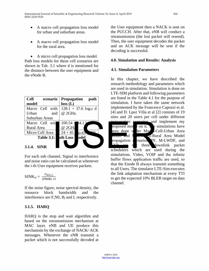
• A macro cell propagation loss model for urban and suburban areas.
• A macro cell propagation loss model for the rural area.
• A micro cell propagation loss model.
Path loss models for these cell scenarios are shown in Tab. 3.1 where d is mentioned for the distance between the user equipment and the eNode B. Cell scenario model
Propagation path loss (L)
Macro Cell with Urban and Suburban Areas
128.1 + 37.6 log10 d @ 2GHz.
Macro Cell with Rural Area
100.54 + 34.1 log10 d @ 2GHz.
Micro Cell Area 24 + 45 log10(d + 20). Table 3.1: Path Loss Model
3.1.4. SINR For each sub channel, Signal to interference and noise ratio can be calculated as whenever the i-th User equipment receives packets. SINRi,j = 𝑃𝑃𝑅𝑅𝑅𝑅,𝑖𝑖,𝑗𝑗
(FN0B) +I
If the noise figure, noise spectral density, the resource block bandwidth and the interference are F,N0, Bj and I, respectively. 3.1.5. HARQ HARQ is the stop and wait algorithm and based on the retransmission mechanism at MAC layer. eNB and UE produce this mechanism by the exchange of NACK/ ACK messages. Whenever the eNB transmit a packet which is not successfully decoded at
the User equipment then a NACK is sent on the PUCCH. After that, eNB will conduct a retransmission (the lost packet will resend). Then, the user equipment decodes the packet and an ACK message will be sent if the decoding is successful. 4.0. Simulation and Results: Analysis 4.1. Simulation Parameters In this chapter, we have described the research methodology and parameters which are used in simulation. Simulation is done on LTE-SIM platform and following parameters are listed in the Table 4.1 for the purpose of simulation. I have taken the same network implemented by the Francesco Capozzi et al. [4] and D. Lpez Villa et al [2] consists of 19 sites and 20 users per cell under different propagation scenarios and implement my proposed model on it. The simulations have been done under Macro-Cell-Urban Area Model and Macro-Cell-Rural Area Model propagation scenarios. PF, M-LWDF, and EXP are the three downlink packet schedulers which are used during the simulations. Video, VOIP and the infinite buffer flows application traffic are used, so that the Enode B always transmit something to all Users. The simulator LTE-Sim executes the link adaptation mechanism at every TTI to get the expected 10% BLER target on data channel.
IJSER
International Journal of Scientific & Engineering Research Volume 10, Issue 4, April-2019 565 ISSN 2229-5518
IJSER © 2019 http://www.ijser.org
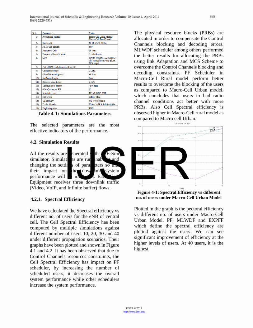
Table 4-1: Simulations Parameters
The selected parameters are the most effective indicators of the performance. 4.2. Simulation Results All the results are generated with LTE-Sim simulator. Simulations are run enabling and changing the settings of parameters so that their impact on the downlink system performance will be measured. Each User Equipment receives three downlink traffic (Video, VoIP, and Infinite buffer) flows. 4.2.1. Spectral Efficiency We have calculated the Spectral efficiency vs different no. of users for the eNB of central cell. The Cell Spectral Efficiency has been computed by multiple simulations against different number of users 10, 20, 30 and 40 under different propagation scenarios. Their graphs have been plotted and shown in Figure 4.1 and 4.2. It has been observed that due to Control Channels resources constraints, the Cell Spectral Efficiency has impact on PF scheduler, by increasing the number of scheduled users, it decreases the overall system performance while other schedulers increase the system performance.
The physical resource blocks (PRBs) are allocated in order to compensate the Control Channels blocking and decoding errors. MLWDF scheduler among others performed the better results for allocating the PRBs using link Adaptation and MCS Scheme to overcome the Control Channels blocking and decoding constraints. PF Scheduler in Macro-Cell Rural model perform better results to overcome the blocking of the users as compared to Macro-Cell Urban model, which concludes that users in bad radio channel conditions act better with more PRBs. Also Cell Spectral efficiency is observed higher in Macro-Cell rural model as compared to Macro cell Urban.
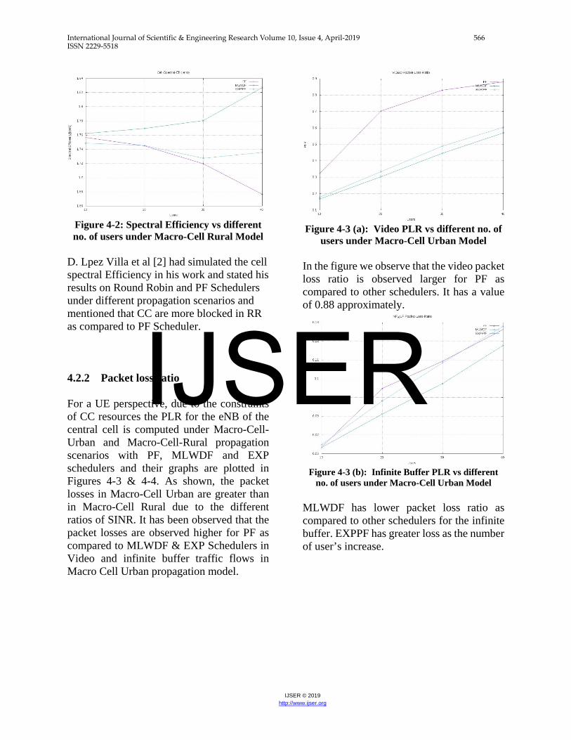
Figure 4-1: Spectral Efficiency vs different
no. of users under Macro-Cell Urban Model Plotted in the graph is the pectoral efficiency vs different no. of users under Macro-Cell Urban Model. PF, MLWDF and EXPFF which define the spectral efficiency are plotted against the users. We can see significant improvement of efficiency at the higher levels of users. At 40 users, it is the highest.
IJSER
International Journal of Scientific & Engineering Research Volume 10, Issue 4, April-2019 566 ISSN 2229-5518
IJSER © 2019 http://www.ijser.org
Figure 4-2: Spectral Efficiency vs different no. of users under Macro-Cell Rural Model
D. Lpez Villa et al [2] had simulated the cell spectral Efficiency in his work and stated his results on Round Robin and PF Schedulers under different propagation scenarios and mentioned that CC are more blocked in RR as compared to PF Scheduler. 4.2.2 Packet loss ratio For a UE perspective, due to the constraints of CC resources the PLR for the eNB of the central cell is computed under Macro-Cell-Urban and Macro-Cell-Rural propagation scenarios with PF, MLWDF and EXP schedulers and their graphs are plotted in Figures 4-3 & 4-4. As shown, the packet losses in Macro-Cell Urban are greater than in Macro-Cell Rural due to the different ratios of SINR. It has been observed that the packet losses are observed higher for PF as compared to MLWDF & EXP Schedulers in Video and infinite buffer traffic flows in Macro Cell Urban propagation model.
Figure 4-3 (a): Video PLR vs different no. of
users under Macro-Cell Urban Model In the figure we observe that the video packet loss ratio is observed larger for PF as compared to other schedulers. It has a value of 0.88 approximately.
Figure 4-3 (b): Infinite Buffer PLR vs different
no. of users under Macro-Cell Urban Model MLWDF has lower packet loss ratio as compared to other schedulers for the infinite buffer. EXPPF has greater loss as the number of user’s increase.
IJSER
International Journal of Scientific & Engineering Research Volume 10, Issue 4, April-2019 567 ISSN 2229-5518
IJSER © 2019 http://www.ijser.org
Figure 4-3 (c): VOIP PLR vs different no. of
users under Macro-Cell Urban Model PF has higher packet loss ratio as compared to other schedulers for voice over the internet (VOIP) transmissions.
Figure 4-4 (a): Video PLR vs different no. of users under Macro-Cell Rural Model
PF have higher packet loss ratio as compared to other schedulers for the transmission of video case. The schedulers are compared to find the best fit or response for the improvement of efficiency.
Figure 4-4 (b): Infinite Buffer PLR vs different no.
of users under Macro-Cell Rural Model MLWDF have lower packet loss ratio as compared to other schedulers for infinite buffer with increase in number of users.
Figure 4-4 (c): VOIP PLR vs different no. of users under Macro-Cell Rural Model
PF have lower packet loss ratio as compared to other schedulers for VOIP. 4.2.2. Throughput. Main simulation parameters are listed in Tab. 4-1. Throughput for the eNB of the central cell has been calculated against the number of users under Macro-Cell Urban model and their graphs have been plotted in Figure 4.5. By increasing the no. of UEs per TTI, it will increase the no. of users to 40 passed by the
IJSER
International Journal of Scientific & Engineering Research Volume 10, Issue 4, April-2019 568 ISSN 2229-5518
IJSER © 2019 http://www.ijser.org
TDPS. In scheduling mechanism, the PDCCH provides more the allocation of resources for UEs. The MLWDF scheduler will compensate in a fair manner and allocate a share of large frequency for UEs at the cell edge. Figure 4-5 have shown that when the number of users touch a total 30 DL/UL UEs, it reached at a saturation point. Francesco Capozzi et al. [4] had simulated and plotted the cell throughput versus users in his work and stated that by increasing the numbers of UEs, it will impact the overall system performance due to control channels constraints and recommended to use power control mechanism.
Figure 4-5 (a): Video Throughput vs
different no. of users at Tx power 46 dbm Video throughput for PF scheduler is decreasing with the increase in no. of users.
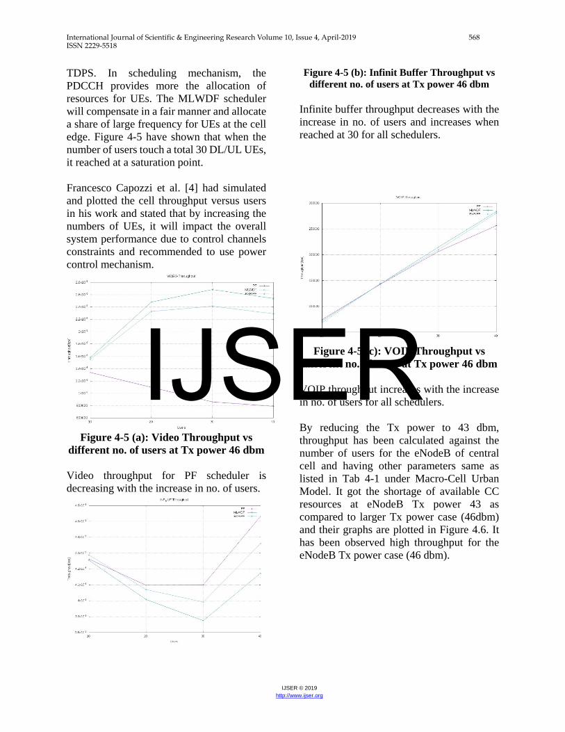
Figure 4-5 (b): Infinit Buffer Throughput vs different no. of users at Tx power 46 dbm
Infinite buffer throughput decreases with the increase in no. of users and increases when reached at 30 for all schedulers.
Figure 4-5 (c): VOIP Throughput vs
different no. of users at Tx power 46 dbm VOIP throughput increases with the increase in no. of users for all schedulers.
By reducing the Tx power to 43 dbm, throughput has been calculated against the number of users for the eNodeB of central cell and having other parameters same as listed in Tab 4-1 under Macro-Cell Urban Model. It got the shortage of available CC resources at eNodeB Tx power 43 as compared to larger Tx power case (46dbm) and their graphs are plotted in Figure 4.6. It has been observed high throughput for the eNodeB Tx power case (46 dbm).
IJSER
International Journal of Scientific & Engineering Research Volume 10, Issue 4, April-2019 569 ISSN 2229-5518
IJSER © 2019 http://www.ijser.org
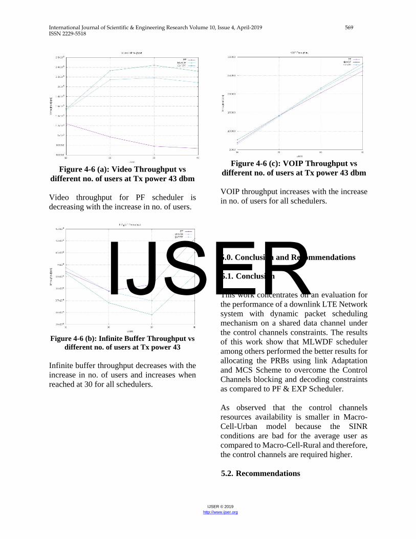
Figure 4-6 (a): Video Throughput vs
different no. of users at Tx power 43 dbm Video throughput for PF scheduler is decreasing with the increase in no. of users.
Figure 4-6 (b): Infinite Buffer Throughput vs
different no. of users at Tx power 43 Infinite buffer throughput decreases with the increase in no. of users and increases when reached at 30 for all schedulers.
Figure 4-6 (c): VOIP Throughput vs
different no. of users at Tx power 43 dbm VOIP throughput increases with the increase in no. of users for all schedulers. 5.0. Conclusion and Recommendations 5.1. Conclusion This work concentrates on an evaluation for the performance of a downlink LTE Network system with dynamic packet scheduling mechanism on a shared data channel under the control channels constraints. The results of this work show that MLWDF scheduler among others performed the better results for allocating the PRBs using link Adaptation and MCS Scheme to overcome the Control Channels blocking and decoding constraints as compared to PF & EXP Scheduler. As observed that the control channels resources availability is smaller in Macro-Cell-Urban model because the SINR conditions are bad for the average user as compared to Macro-Cell-Rural and therefore, the control channels are required higher. 5.2. Recommendations
IJSER
International Journal of Scientific & Engineering Research Volume 10, Issue 4, April-2019 570 ISSN 2229-5518
IJSER © 2019 http://www.ijser.org
It is recommended to use a M-LWDF scheduler and Power Control mechanism for better performance of control channels on LTE network system as it spreads the cell coverage and when the cell load is bigger, it will have scheduled a higher number of users simultaneously and hence, it will achieve a higher frequency diversity gain. Further, it is mentioned that by the Control Channel Manager when increasing the number of schedulable users will reduce the CC blocking and enhance the system coverage while interacting with a M-LWDF scheduler. To meet the control channel BLER remains around 10%, a link adaptation mechanism are required. CQI wideband SINR reports based on more realistic are future step in this research.
References [1] Omar Kayali, Mohamad & Shmeiss, Zeinab & Safa, Haidar & El-Hajj, Wassim. (2017). Downlink scheduling in LTE: Challenges, improvement, and analysis. 323-328. 10.1109/IWCMC.2017.7986307. [2] Villa, D.L., Castellanos, C.U., Kovács, I.Z., Frederiksen, F., & Pedersen, K.I. (2008). Performance of Downlink UTRAN LTE under Control Channel Constraints. VTC Spring 2008 - IEEE Vehicular Technology Conference, 2512-2516. [3] Cai Sen , Ji Hong , Li Xi, “On the Impact of Realistic Control Channel Constraints on QoS Provisioning in UTRAN LTE”, VTC-2009. [4] Apozzi, Francesco & Laselva, Daniela & Frederiksen, Frank & Wigard, J & Z. Kovacs, Istvan & E. Mogensen, Preben. (2009). UTRAN LTE Downlink System Performance under Realistic Control
Channel Constraints. 1 - 5. 10.1109/VETECF.2009.5378831. [5] M. Einhaus et al, “Performance Study of an Enhanced Downlink Control Channel Design for LTE”, VTC 2012. [6] Li Li, Mugen Peng, Wenbo Wang, “Multi-User Resource Allocation for Downlink Control Channel in LTE Systems”, PIMRC 2010. [7] Yonghui CHEN, “Resource Allocation for Downlink Control Channel in LTE Systems”, WICOM, 2011. [8] Jiri Milos, Stanislav Hanu, "Performance Analysis of PCFICH and PDCCH LTE Control Channel ", APRIL 2014. [9] Wen-Bin Yang, Michael Souryal, "LTE Physical Layer Performance Analysis ", December 2013. [10] Shih-Jung WU, “A Channel Quality-aware Scheduling and Resource Allocation Strategy for Downlink LTE Systems", Journal of Computational Information Systems, 2012.
IJSER