Embed Size (px)
Citation preview
Diagnosing Channel Issues Using GTP ProtocolMessages in LTE Core Networks
Saman Feghhi∗, John Keeney†, Liam Fallon†, Douglas J. Leith∗∗School of Computer Science & Statistics, Trinity College Dublin, Ireland.
{feghhis, Doug.Leith}@tcd.ie†Network Management Lab, Ericsson, Athlone, Ireland.
{John.Keeney, Liam.Fallon}@ericsson.com
Abstract—For some time now the volume of data traffic inMobile Telecommunications Networks has far outweighed voicetraffic and most users are more concerned about the qualityof their data connection than their voice calls. Adequate trafficservice requires analysis of traffic flows to identify network issuesaffecting users’ services. This can be achieved by placing networkanalytics probes throughout the network, but it would be betterto have a small number of probes at just key locations in theMobile Core Network. We show how to use core network trafficanalysis to identify which user owns and which base station hostseach traffic flow, particularly where users and their connectedtraffic flows may dynamically switch between base stations orradio technologies.
I. INTRODUCTION
Modern telecommunications networks need constant monitor-ing and management to operate effectively. Traditional Op-erating Support Systems (OSS) constantly gather informationfrom network nodes to analyse the operation of the networkand the services that use the network. In almost all current Mo-bile Telecommunications Networks (e.g. 3G and LTE), data-traffic volumes are much higher than voice traffic volumes. Inaddition to collecting performance events and counters fromnetwork nodes there is potential to examine the characteristicsof the data traffic to diagnose issues in the network.
The challenge when dealing with current mobile networks isthe enormous volume of user data and control messages thatare being transmitted throughout the network. Given the scaleof messages which must be processed in real-time for effectivenetwork analysis, collecting data from all nodes and interfacesin the network is clearly not plausible.
The solution is to find a minimal set of key interfaces fromwhich to gather measurements that characterise the live statusof the network and the services being delivered to subscribers.To this end we describe a method to collect information aboutthe traffic of users to analyse the performance of the mobilenetwork in handling that traffic. This data is gathered byinserting the minimum number of network traffic probes at keypositions in the Core Network (CN), the part of the networkthat operates between the network operator’s Radio AccessNetwork (RAN) and the public Internet.
In Section II we review the definition of GPRS TunnellingProtocol (GTP), used to control and carry user-plane traffic in
This work was partly supported by Science Foundation Ireland under GrantNo. 11/PI/1177.
mobile core networks. We also provide an overview of CoreNetwork nodes, links and topology. Section III explains ourapproach for network measurement collection, and the chal-lenges we encountered. In section IV we assess our approachon a real medium-sized 3G/LTE mobile network. Section Vdiscusses current and future applications of our method.
II. MOBILE CORE NETWORK TOPOLOGY
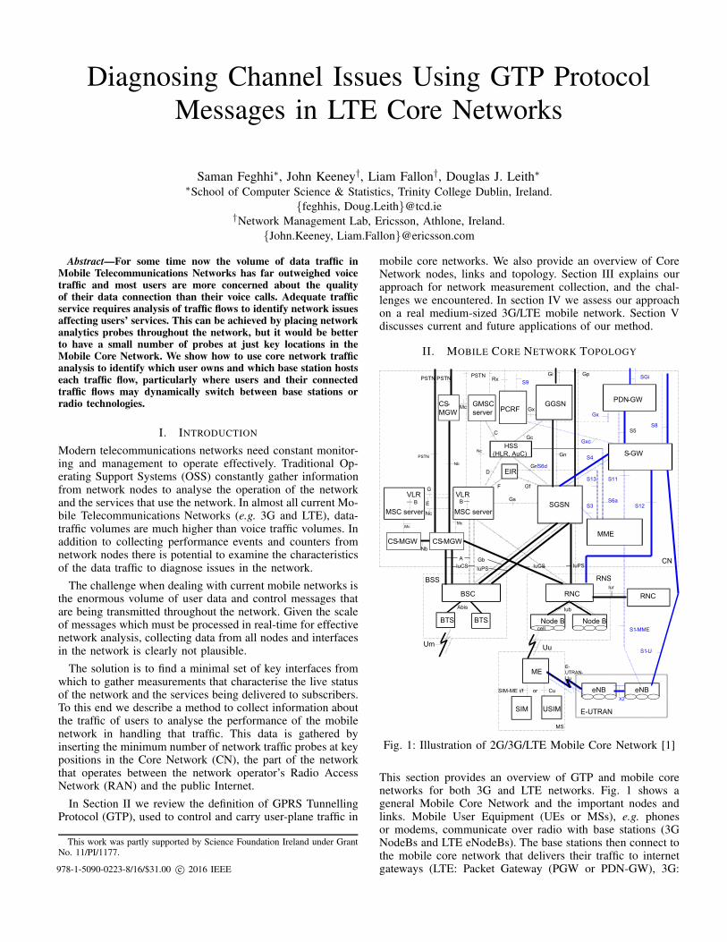
Fig. 1: Illustration of 2G/3G/LTE Mobile Core Network [1]
This section provides an overview of GTP and mobile corenetworks for both 3G and LTE networks. Fig. 1 shows ageneral Mobile Core Network and the important nodes andlinks. Mobile User Equipment (UEs or MSs), e.g. phonesor modems, communicate over radio with base stations (3GNodeBs and LTE eNodeBs). The base stations then connect tothe mobile core network that delivers their traffic to internetgateways (LTE: Packet Gateway (PGW or PDN-GW), 3G:978-1-5090-0223-8/16/$31.00 c© 2016 IEEE
Gateway GPRS Support Node (GGSN)). While the physicalpath between the UE and the internet gateways may varydepending on UE movement etc, all data traffic is tunnelledover various nodes and links between the gateway and the UEusing the GPRS Tunnelling Protocol (GTP) to create a stablevirtual link between the two nodes. These tunnels are oftenreferred to as “bearers” in LTE or “contexts” in 3G.
A. 3G Core Network
3G networks consist of two major parts: the traditional circuit-switched network that handles voice calls, and the packet-switched network which handles data communications. Traf-fic coming from a UE first arrives over radio to whateverbase station (NodeB) the UE is currently connected to. EachNodeB can serve one or more radio cells or sectors providingradio coverage in its surrounding area. Pools of NodeBsare then controlled by a Radio Network Controller (RNC)which coordinates the NodeBs and delivers the traffic to anSGSN (Serving GPRS Support Node). The SGSN then routespackets based on charging and policy information receivedfrom the PCRF (Policy and Charging Rules Function) throughan appropriate GGSN internet gateway.
B. LTE Core Network
In an LTE core network (Evolved Packet Core) RNC functionsare performed in the eNodeB base station. LTE supports onlypacket data so data packets are sent from the eNodeB to theServing Gateway (S-GW). The MME (Mobility ManagementEntity) node is responsible for coordinating UE mobility andalso for establishing and maintaining all traffic bearers fromUEs to an internet gateway (PDN-GW). Most LTE core net-work nodes maintain interconnections with 3G core networknodes to support backwards compatibility and 2G/3G/LTEhandovers, especially since traditional circuit switched voicecalls are not natively supported in LTE and fall back to 2G/3G.
C. GTP Protocol
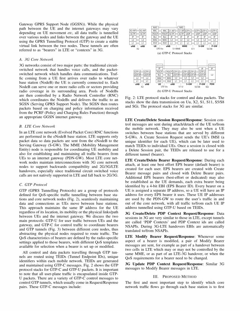
GTP (GPRS Tunnelling Protocols) are a group of protocolsdefined for QoS-specific traffic tunnelling between base sta-tions and core network nodes (Fig. 2), seamlessly maintainingdata and connections as UEs move between base stations.This approach maintains the same IP address for the UEregardless of its location, its mobility or the physical links/pathbetween UEs and the internet gateway. We discuss the twomain protocols: GTP-U for user traffic between UEs and thegateway, and GTP-C for control traffic to coordinate bearersand GTP tunnels (Fig. 3) between different core nodes, thusabstracting the physical nodes required to route traffic. TheQoS characteristics of bearers are defined by the radio-specificsettings applied to those bearers, with different QoS templatesavailable for selection when a bearer is set up or modified.
All control and data packets travelling through GTP tun-nels are routed using TEIDs (Tunnel Endpoint IDs), uniqueidentifiers within each mobile network. TEIDs are generatedand maintained using GTP-C messages. Fig. 2 shows the GTPprotocol stacks for GTP-C and GTP-U packets. It is importantto note that all user-plane traffic is encapsulated inside GTP-U packets. There are a variety of GTP-C control messages tocontrol GTP tunnels, which usually come in Request/Responsepairs. These GTP-C messages include:
PHY
MAC
RLC
PDCP
RRC
MAC
PHY
RLC
PDCP
L1
L2
IP
UE eNB P-GW
LTE-Uu S1-MME S11S-GW
NAS
SCTP
S1-APRRC
L2
L1
IP
SCTP
L1
L2
IP
MME
UDP
GTP-CS1-AP
NAS
L2
L1
IP
UDP
L1
L2
IP
UDP
GTP-CGTP-C
L1
L2
IP
UDP
GTP-C
S5/S8eNB
L1
L2
IP
SCTP
X2-AP
L1
L2
IP
SCTP
X2-AP
X2eNB
(a) GTP-C Protocol Stacks
PHY
MAC
RLC
PDCP
IP
MAC
PHY
RLC
PDCP
L1
L2
UDP/IP
UE eNB PDN
LTE-Uu S1-U S5/S8
Application
GTP-U
L2
L1
UDP/IP
GTP-U
L1
L2
UDP/IP
S-GW
GTP-U
L1
L2
IP
SGieNB
L1
L2
UDP/IP
GTP-U
L1
L2
UDP/IP
GTP-U
X2eNB P-GW
L1
L2
UDP/IP
GTP-U
IP
Application
(b) GTP-U Protocol Stacks
Fig. 2: LTE protocol stacks for control and data packets. Thestacks show the data transmission on Uu, X2, S1, S11, S5/S8and SGi. The protocol stacks for 3G are similar.
LTE Create/Delete Session Request/Response: Session con-trol messages are sent during attach/detach of the UE to/fromthe mobile network. They may also be sent when a UEswitches between base stations that are served by differentS-GWs. A Create Session Request sends the UE’s IMSI (aunique identifier for each UE), which can be later used tomatch TEIDs to individual UEs. Once a session is closed witha Delete Session pair, the TEIDs are released to use for adifferent tunnel (bearer).
LTE Create/Delete Bearer Request/Response: During eachattach, at least one best effort EPS bearer (default bearer) iscreated for each user. EPS bearers are created with CreateBearer message pairs and closed with Delete Bearer pairs.Additional EPS bearers (best-effort or dedicated) may alsobe established as the UE demands, each extra bearer beingidentified by a 4-bit EBI (EPS Bearer ID). Every bearer on aUE is assigned a separate IP address, so a UE will have an IPaddress for every EPS bearer it uses. These UE IP addressesare used by the PDN-GW to route the user’s traffic in andout of the core network, with all traffic to/from each UE IPaddress tunnelled using GTP-U based on TEIDs.
3G Create/Delete PDP Context Request/Response: Datasessions in 3G are very similar to those in LTE, except tunnelsare called ‘PDP Contexts’ and PDP Context ids are calledNSAPIs. During 3G-LTE handovers EBIs are automaticallytranslated to/from NSAPIs.
LTE Modify Bearer Request/Response: Whenever someaspect of a bearer is modified, a pair of Modify Bearermessages are sent, for example as part of a handover betweentwo cells in LTE which may or may not be controlled by thesame MME, or as part of an LTE-3G handover, or when theQoS requirements for a bearer need to be changed.
3G Update PDP Context Request/Response: Similar 3Gmessages to Modify Bearer messages in LTE.
III. PROPOSED METHOD
The first and most important step to identify which corenetwork traffic flows go through each base station is to first
End-to-end Service
UE eNB SGW PDN-GW Peer
Entity
Radio S1 S5 Gi
InternetEPCE-UTRAN
EPS Bearer External Bearer
E-RAB S5 Bearer
Radio Bearer S1 Bearer
EPS Bearer ID
E-RAB ID
S5 TEID (UL/DL)S1 TEID (UL/DL)RB ID
APN
(PDN ID)
UE IP ADDRESS
(PDN ADDRESS)
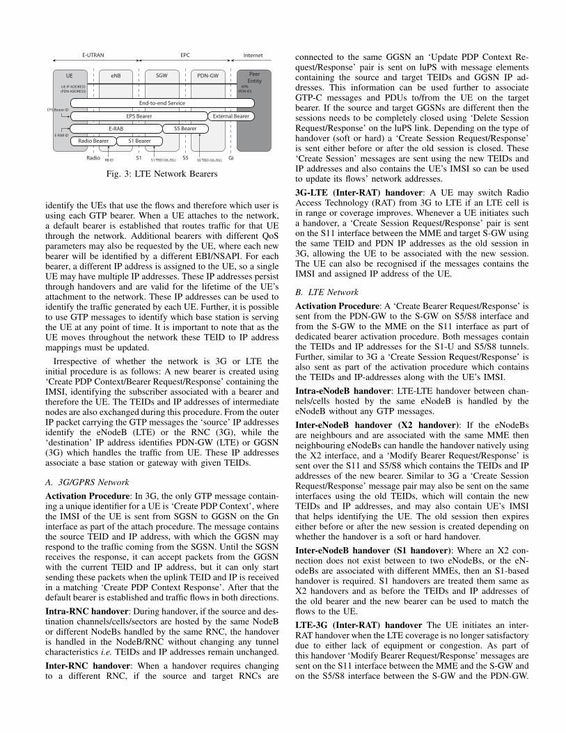
Fig. 3: LTE Network Bearers
identify the UEs that use the flows and therefore which user isusing each GTP bearer. When a UE attaches to the network,a default bearer is established that routes traffic for that UEthrough the network. Additional bearers with different QoSparameters may also be requested by the UE, where each newbearer will be identified by a different EBI/NSAPI. For eachbearer, a different IP address is assigned to the UE, so a singleUE may have multiple IP addresses. These IP addresses persistthrough handovers and are valid for the lifetime of the UE’sattachment to the network. These IP addresses can be used toidentify the traffic generated by each UE. Further, it is possibleto use GTP messages to identify which base station is servingthe UE at any point of time. It is important to note that as theUE moves throughout the network these TEID to IP addressmappings must be updated.
Irrespective of whether the network is 3G or LTE theinitial procedure is as follows: A new bearer is created using‘Create PDP Context/Bearer Request/Response’ containing theIMSI, identifying the subscriber associated with a bearer andtherefore the UE. The TEIDs and IP addresses of intermediatenodes are also exchanged during this procedure. From the outerIP packet carrying the GTP messages the ‘source’ IP addressesidentify the eNodeB (LTE) or the RNC (3G), while the‘destination’ IP address identifies PDN-GW (LTE) or GGSN(3G) which handles the traffic from UE. These IP addressesassociate a base station or gateway with given TEIDs.
A. 3G/GPRS Network
Activation Procedure: In 3G, the only GTP message contain-ing a unique identifier for a UE is ‘Create PDP Context’, wherethe IMSI of the UE is sent from SGSN to GGSN on the Gninterface as part of the attach procedure. The message containsthe source TEID and IP address, with which the GGSN mayrespond to the traffic coming from the SGSN. Until the SGSNreceives the response, it can accept packets from the GGSNwith the current TEID and IP address, but it can only startsending these packets when the uplink TEID and IP is receivedin a matching ‘Create PDP Context Response’. After that thedefault bearer is established and traffic flows in both directions.
Intra-RNC handover: During handover, if the source and des-tination channels/cells/sectors are hosted by the same NodeBor different NodeBs handled by the same RNC, the handoveris handled in the NodeB/RNC without changing any tunnelcharacteristics i.e. TEIDs and IP addresses remain unchanged.
Inter-RNC handover: When a handover requires changingto a different RNC, if the source and target RNCs are
connected to the same GGSN an ‘Update PDP Context Re-quest/Response’ pair is sent on luPS with message elementscontaining the source and target TEIDs and GGSN IP ad-dresses. This information can be used further to associateGTP-C messages and PDUs to/from the UE on the targetbearer. If the source and target GGSNs are different then thesessions needs to be completely closed using ‘Delete SessionRequest/Response’ on the luPS link. Depending on the type ofhandover (soft or hard) a ‘Create Session Request/Response’is sent either before or after the old session is closed. These‘Create Session’ messages are sent using the new TEIDs andIP addresses and also contains the UE’s IMSI so can be usedto update its flows’ network addresses.
3G-LTE (Inter-RAT) handover: A UE may switch RadioAccess Technology (RAT) from 3G to LTE if an LTE cell isin range or coverage improves. Whenever a UE initiates sucha handover, a ‘Create Session Request/Response’ pair is senton the S11 interface between the MME and target S-GW usingthe same TEID and PDN IP addresses as the old session in3G, allowing the UE to be associated with the new session.The UE can also be recognised if the messages contains theIMSI and assigned IP address of the UE.
B. LTE Network
Activation Procedure: A ‘Create Bearer Request/Response’ issent from the PDN-GW to the S-GW on S5/S8 interface andfrom the S-GW to the MME on the S11 interface as part ofdedicated bearer activation procedure. Both messages containthe TEIDs and IP addresses for the S1-U and S5/S8 tunnels.Further, similar to 3G a ‘Create Session Request/Response’ isalso sent as part of the activation procedure which containsthe TEIDs and IP-addresses along with the UE’s IMSI.
Intra-eNodeB handover: LTE-LTE handover between chan-nels/cells hosted by the same eNodeB is handled by theeNodeB without any GTP messages.
Inter-eNodeB handover (X2 handover): If the eNodeBsare neighbours and are associated with the same MME thenneighbouring eNodeBs can handle the handover natively usingthe X2 interface, and a ‘Modify Bearer Request/Response’ issent over the S11 and S5/S8 which contains the TEIDs and IPaddresses of the new bearer. Similar to 3G a ‘Create SessionRequest/Response’ message pair may also be sent on the sameinterfaces using the old TEIDs, which will contain the newTEIDs and IP addresses, and may also contain UE’s IMSIthat helps identifying the UE. The old session then expireseither before or after the new session is created depending onwhether the handover is a soft or hard handover.
Inter-eNodeB handover (S1 handover): Where an X2 con-nection does not exist between to two eNodeBs, or the eN-odeBs are associated with different MMEs, then an S1-basedhandover is required. S1 handovers are treated them same asX2 handovers and as before the TEIDs and IP addresses ofthe old bearer and the new bearer can be used to match theflows to the UE.
LTE-3G (Inter-RAT) handover The UE initiates an inter-RAT handover when the LTE coverage is no longer satisfactorydue to either lack of equipment or congestion. As part ofthis handover ‘Modify Bearer Request/Response’ messages aresent on the S11 interface between the MME and the S-GW andon the S5/S8 interface between the S-GW and the PDN-GW.
An ‘Update PDP Context Request/Response’ message pair canalso be seen on the luPS interface, which uses the same TEIDsand IP addresses from the original LTE session.
C. Tracing Network Flows to Identify Congestion
Since it is now possible to track flows from all UEs, thechallenge is to determine which base station is serving a UE atany point of time, and so bundle the UE traffic loads accordingto the base stations currently hosting those UEs. For LTE, thisinformation can be obtained using the UDP PDU packets thatcarry the GTP messages. The source IP address of the UDP/IPheader that represents the eNodeB that sends or receives theUDP packet is used so that the throughput of each eNodeBcan be estimated without knowing the origin of the flows.
The situation is more complex in 3G. The source IP addressno longer belongs to the NodeB but to the RNC which controlsa set of NodeBs. Communication between an RNC and itschild NodeBs are not seen in the core network. With thisapproach it is possible to estimate the load of each RNC butit is not possible to further partition this load for the NodeBscontrolled by that RNC. Therefore, with 3G, it is not possibleto rely only on GTP messages on the core network interfaces.However in any RAN OSS system there will be other readilyavailable data sources to identify which base station hostswhich UE such as monitoring events from SGSN/MME, cellsand UEs, which, when correlated with the GTP data makes itpossible to localise individual flows to particular NodeBs.
While data traffic is most likely to cause congestion ina base station it is not the only traffic through the basestation. Other traffic includes voice call traffic, SMS traffic,and management traffic. This traffic is not transported usingGTP. Therefore a challenge remains to trace and track thistraffic, which currently remains a considerable but relativelydeterministic traffic volume. However with relative growth indata traffic and the growth of VoLTE (Voice over LTE) andinternet services as an alternative to traditional circuit switchvoice communications, this proportion of the traffic that is nottransported over GTP is rapidly decreasing.
IV. ANALYSIS OF A REAL MOBILE NETWORK
We used the method described in §III to analyse the GTPtraffic from a real mobile network. We used a number of deep-packet inspection (DPI) probes to analyse GTP-C traffic onkey interfaces in a segment of a medium-sized 3G/4G mobilenetwork. Using the information from GTP headers, we wereable to analyse the behaviour of user traffic in the network.
A. Experimental Setup
We used probes to collect GTP control messages over the S1and X2 and equivalent 3G interfaces. For the purposes of thispaper, the analysis was scoped to one hour of traffic collectedbetween 20:00 and 21:00 local time, peak hour for data traffic.The traffic was collected on both 3G and LTE interfaces andwas then classified by criteria such as UE, cell, and (e)NodeBusing our method. We then interpreted this information toanalyse the network behaviour. In this section we present somestatistics derived from that hour of inspected data.
3G LTE
IMSIs 189638 390583IP addresses 234787 479233
UTRAN/EUTRAN Cells 3830 1Service Areas 18139 1Routing Areas 23 1Tracking Areas 1 1Location Areas 1 1
TABLE I: 3G & 4G nodes seen in Network Segment in 1 hour
Network Type Create Update Delete
3G 511589 53209 91047LTE 769329 19519365 747464
TABLE II: GTP-C messages seen in Network Segment in 1 hour
B. Statistics and Results
Using information from create session messages, we evaluatedthe number of active users on the network. Further we usedupdate session messages to track users in the network and inturn count the active cells as well as Service, Routing, Track-ing, and Location Areas. Table I summarises these statistics.
The number of create, update and delete messages for 3Gand LTE network are summarised in table II. We noticed thatthe number of LTE session messages are relatively higher thanthose of 3G, which is due to a much higher usage of LTE than3G for data traffic with this operator. This can be confirmed bylooking at the number of IMSIs and IP addresses that appearedin LTE GTP messages which are almost twice those in 3G.
0
5000
10000
15000
20000
25000
30000
35000
40000
0 2 4 6 8 10 12 14 16 18 20 22 24 26 28 30 32 34 36 38 40 42 44 46 48 50 52 54 56 58 60
# M
essa
ge
s
Minute
3G Create Messages3G Update Messages3G Delete Messages4G Create Messages
4G Update Messages/104G Delete Messages
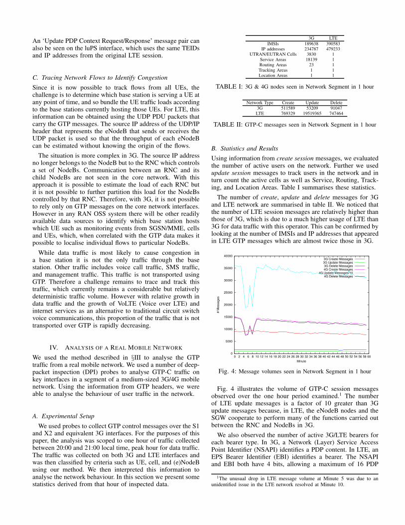
Fig. 4: Message volumes seen in Network Segment in 1 hour
Fig. 4 illustrates the volume of GTP-C session messagesobserved over the one hour period examined.1 The numberof LTE update messages is a factor of 10 greater than 3Gupdate messages because, in LTE, the eNodeB nodes and theSGW cooperate to perform many of the functions carried outbetween the RNC and NodeBs in 3G.
We also observed the number of active 3G/LTE bearers foreach bearer type. In 3G, a Network (Layer) Service AccessPoint Identifier (NSAPI) identifies a PDP content. In LTE, anEPS Bearer Identifier (EBI) identifies a bearer. The NSAPIand EBI both have 4 bits, allowing a maximum of 16 PDP
1The unusual drop in LTE message volume at Minute 5 was due to anunidentified issue in the LTE network resolved at Minute 10.
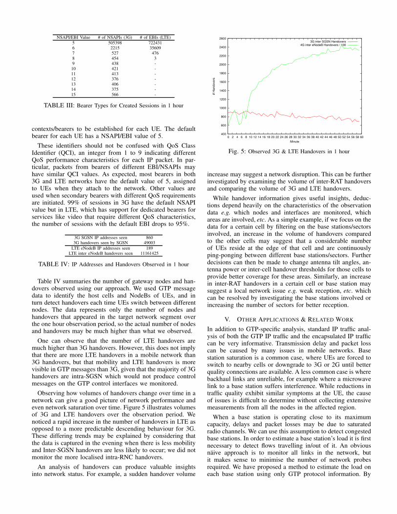
NSAPI/EBI Value # of NSAPIs (3G) # of EBIs (LTE)
5 505398 7224316 2215 356097 527 4768 454 39 438 -
10 421 -11 413 -12 376 -13 406 -14 375 -15 566 -
TABLE III: Bearer Types for Created Sessions in 1 hour
contexts/bearers to be established for each UE. The defaultbearer for each UE has a NSAPI/EBI value of 5.
These identifiers should not be confused with QoS ClassIdentifier (QCI), an integer from 1 to 9 indicating differentQoS performance characteristics for each IP packet. In par-ticular, packets from bearers of different EBI/NSAPIs mayhave similar QCI values. As expected, most bearers in both3G and LTE networks have the default value of 5, assignedto UEs when they attach to the network. Other values areused when secondary bearers with different QoS requirementsare initiated. 99% of sessions in 3G have the default NSAPIvalue but in LTE, which has support for dedicated bearers forservices like video that require different QoS characteristics,the number of sessions with the default EBI drops to 95%.
3G SGSN IP addresses seen 8603G handovers seen by SGSN 49003
LTE eNodeB IP addresses seen 189LTE inter eNodeB handovers seen 11161425
TABLE IV: IP Addresses and Handovers Observed in 1 hour
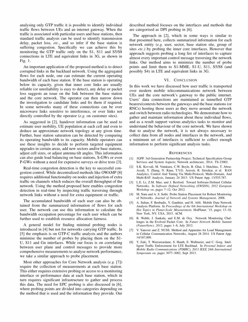
Table IV summaries the number of gateway nodes and han-dovers observed using our approach. We used GTP messagedata to identify the host cells and NodeBs of UEs, and inturn detect handovers each time UEs switch between differentnodes. The data represents only the number of nodes andhandovers that appeared in the target network segment overthe one hour observation period, so the actual number of nodesand handovers may be much higher than what we observed.
One can observe that the number of LTE handovers aremuch higher than 3G handovers. However, this does not implythat there are more LTE handovers in a mobile network than3G handovers, but that mobility and LTE handovers is morevisible in GTP messages than 3G, given that the majority of 3Ghandovers are intra-SGSN which would not produce controlmessages on the GTP control interfaces we monitored.
Observing how volumes of handovers change over time in anetwork can give a good picture of network performance andeven network saturation over time. Figure 5 illustrates volumesof 3G and LTE handovers over the observation period. Wenoticed a rapid increase in the number of handovers in LTE asopposed to a more predictable descending behaviour for 3G.These differing trends may be explained by considering thatthe data is captured in the evening when there is less mobilityand Inter-SGSN handovers are less likely to occur; we did notmonitor the more localised intra-RNC handovers.
An analysis of handovers can produce valuable insightsinto network status. For example, a sudden handover volume
400
600
800
1000
1200
1400
1600
1800
2000
2200
2400
2600
0 2 4 6 8 10 12 14 16 18 20 22 24 26 28 30 32 34 36 38 40 42 44 46 48 50 52 54 56 58 60
# H
an
do
ve
rs
Minute
3G inter SGSN Handovers4G inter eNodeB Handovers / 100
Fig. 5: Observed 3G & LTE Handovers in 1 hour
increase may suggest a network disruption. This can be furtherinvestigated by examining the volume of inter-RAT handoversand comparing the volume of 3G and LTE handovers.
While handover information gives useful insights, deduc-tions depend heavily on the characteristics of the observationdata e.g. which nodes and interfaces are monitored, whichareas are involved, etc. As a simple example, if we focus on thedata for a certain cell by filtering on the base stations/sectorsinvolved, an increase in the volume of handovers comparedto the other cells may suggest that a considerable numberof UEs reside at the edge of that cell and are continuouslyping-ponging between different base stations/sectors. Furtherdecisions can then be made to change antenna tilt angles, an-tenna power or inter-cell handover thresholds for those cells toprovide better coverage for these areas. Similarly, an increasein inter-RAT handovers in a certain cell or base station maysuggest a local network issue e.g. weak reception, etc. whichcan be resolved by investigating the base stations involved orincreasing the number of sectors for better reception.
V. OTHER APPLICATIONS & RELATED WORK
In addition to GTP-specific analysis, standard IP traffic anal-ysis of both the GTP IP traffic and the encapsulated IP trafficcan be very informative. Transmission delay and packet losscan be caused by many issues in mobile networks. Basestation saturation is a common case, where UEs are forced toswitch to nearby cells or downgrade to 3G or 2G until betterquality connections are available. A less common case is wherebackhaul links are unreliable, for example where a microwavelink to a base station suffers interference. While reductions intraffic quality exhibit similar symptoms at the UE, the causeof issues is difficult to determine without collecting extensivemeasurements from all the nodes in the affected region.
When a base station is operating close to its maximumcapacity, delays and packet losses may be due to saturatedradio channels. We can use this assumption to detect congestedbase stations. In order to estimate a base station’s load it is firstnecessary to detect flows travelling in/out of it. An obviousnaive approach is to monitor all links in the network, butit makes sense to minimise the number of network probesrequired. We have proposed a method to estimate the load oneach base station using only GTP protocol information. By
analysing only GTP traffic it is possible to identify individualtraffic flows between UEs and an internet gateway. When thetraffic is associated with particular users and base stations, thenstandard traffic analysis can be used to identify transmissiondelay, packet loss, etc., and so infer if the base station issuffering congestion. Specifically we can achieve this bymonitoring the GTP traffic only on the S1, S11 and S5/S8connections in LTE and equivalent links in 3G, as shown inFig. 1.
An important application of the proposed method is to detectcorrupted links in the backhaul network. Using the aggregatedflows for each node, one can estimate the current operatingbandwidth of each base station. If the base station is operatingbelow its capacity, given that inner core links are usuallyreliable (or unreliability is easy to detect), any delay or packetloss suggests an issue on the link between the base stationand the core network. The operator can then narrow downthe investigation to candidate links and fix them if required.In some networks many of these connections can be overmicrowave links sensitive to interference, or over links notdirectly controlled by the operator (e.g. on customer sites).
As suggested in [2], handover information can be used toestimate user mobility, UE population at each cell and even todeduce an approximate network topology at any given time.Further, base station saturation can be detected by comparingits operating bandwidth to its capacity. Mobile operators canuse these insights to decide to perform targeted equipmentupgrades in certain areas, add new sectors and/or base stations,adjust cell sizes, or adjust antenna tilt angles. This informationcan also guide load balancing on base stations, S-GWs or evenP-GWs without a need for expensive surveys or drive tests [3].
Real-time congestion detection is the key to successful con-gestion control. While decentralized methods like OWAMP [8]requires additional functionality on nodes and injection of extratraffic on channels which reduces the overall throughput of thenetwork. Using the method proposed here enables congestiondetection in real-time by inspecting traffic traversing throughnetwork links without a need for extra equipment or traffic.
The accumulated bandwidth of each user can also be ob-tained from the summarized information of flows for eachuser. The network can use this information to calculate thebandwidth occupation percentage for each user which can befurther used to establish resource allocation fairness.
A general model for finding minimal probing nodes isintroduced in [4] but not for networks carrying GTP traffic. In[5] the emphasis is on GTP-C traffic analysis and the authorsminimise the number of probes by placing them on the S1-U, S11 and Gn interfaces. While our focus is on correlatingbetween user plane and control messages to provide morecomprehensive measurements to analyse network performance,we take a similar approach to probe placement.
Most other approaches for Core Network analysis (e.g. [7])require the collection of measurements at each base station.This either requires extensive probing or access to a monitoringinterface or performance data at each base station, which inturn requires significant infrastructure to gather and processthis data. The need for EPC probing is also discussed in [6],where probing points are divided into categories depending onthe method that is used and the information they provide. Our
described method focuses on the interfaces and methods thatare categorised as DPI probing in [6].
The approach in [2], which in some ways is similar tothat presented here, collects summarized information for eachnetwork entity (e.g. user, sector, base station site, group ofsites etc.) by probing the inner core interfaces. However thatapproach suggests probing a long list of interfaces to capturealmost every important control message traversing the networklinks. Our method aims to minimize the number of probepoints and limit them to S1-MME, S1-U, S11, S5/S8 (andpossibly S4) in LTE and equivalent links in 3G.
VI. CONCLUSION
In this work we have discussed how user traffic is transportedover modern mobile telecommunications network betweenUEs and the core network’s gateway to the public internet.Users’ data connections are maintained as tunnelled GTPbearers/contexts between the gateways and the base stations (orRNCs) hosting those users as they move around the networkand switch between radio technologies. We demonstrate how togather and maintain information about these individual flows,and as a result support various analytics tasks to monitor andunderstand the behaviour of the core network. We have shownthat to analyse the network, it is not always necessary tocollect data from all nodes and interfaces in the network, anda minimum set of interfaces is sufficient to collect enoughinformation to perform significant analysis tasks.
REFERENCES
[1] 3GPP. 3rd Generation Partnership Project; Technical Specification GroupServices and System Aspects; Network architecure, 2014. TS-23002.
[2] S.K. Kovvali, M. Vutukuru, C.W. Boyle, R. Ghai, J. Hutchins, T. Abou-Assali, Y. Zhang, N. Rana, T.V.G. Araveti, R. Sirisikar, et al. RANAnalytics, Control And Tuning Via Multi-Protocol, Multi-Domain, AndMulti-RAT Analysis, January 24 2013. US Patent App. 13/555,787.
[3] L.E. Li, Z.M. Mao, and J. Rexford. Toward Software-Defined CellularNetworks. In Software Defined Networking (EWSDN), 2012 European
Workshop on, pages 7–12, Oct 2012.
[4] M. Natu and A. S. Sethi. Probe Station Placement for Robust Monitoringof Networks. Journal of Network and Systems Management, 2008.
[5] A. Sultan, F. Benbadis, V. Gauthier, and H. Afifi. Mobile Data NetworkAnalysis Platform. In Proceedings of the 6th International Workshop on
Hot Topics in Planet-Scale Measurement, HotPlanet ’15, pages 13–18,New York, NY, USA, 2015. ACM.
[6] B. Wehbi, J. Sankala, and E.M. de Oca. Network Monitoring Chal-lenges in the Evolved Packet Core. In Future Network Mobile Summit
(FutureNetw), 2012, pages 1–8, July 2012.
[7] V. Yanover and Z. NUSS. Method and Apparatus for Load Managementin Cellular Communication Networks, August 28 2014. US Patent App.14/187,009.
[8] Y. Zaki, T. Weerawardane, S. Hauth, E. Wallmeier, and C. Gorg. Intel-ligent Traffic Enforcement for LTE Backhaul. In Personal Indoor and
Mobile Radio Communications (PIMRC), 2013 IEEE 24th International
Symposium on, pages 3077–3082, Sept 2013.