Embed Size (px)
Citation preview
IJCST Vol. 6, ISSue 2, AprIl - June 2015
w w w . i j c s t . c o m InternatIonal Journal of Computer SCIenCe and teChnology 127
ISSN : 0976-8491 (Online) | ISSN : 2229-4333 (Print)
Performance Analysis of Ad-Hoc Routing Protocols for VANET Using NS2 Simulation
1Ameer Ali, 2Dr. Latha C.A1,2Dept. of CSE, Don Bosco Institute of Technology, Bangalore, Karnataka INDIA
AbstractVehicle Ad hoc Networks (VANET) emerged as a subset of the Mobile Ad hoc Network (MANET) application; it is considered to be a significant approach to the ITS (Intelligent Transportation System). VANETs are introduced to assist drivers and improve safety issues and driving comfort, as a step towards constructing a safer, smoother, cleaner and more intelligent environment. At the present time vehicles are equipped with On Board Units (OBU) this enables vehicles to sense situations affecting other vehicles and manage communications. VANET is a new communication paradigm that enables the communication between vehicles moving at high speeds on the roads. This inspired to develop several new applications like, traffic engineering, traffic management, dissemination of emergency information to avoid hazardous situations and other user applications.802.11p, also known as WAVE, is a standard protocol intended for future traffic systems in order to support safety and commercial non-safety applications for vehicular communication. 802.11p is amended from 802.11a, and both are based on OFDM. The main difference between 802.11a and 802.11p is that 802.11p uses 10 MHz frequency bandwidth (half of bandwidth of 802.11a) in order to make the signal more robust against fading and increase the tolerance. This paper investigate the performance of 802.11p for Vehicle-to-Vehicle communication through real-world experiments using different adhoc routing protocols. We measure throughput and packet losses of 802.11pin urban environments. In addition, the performance of routing protocol with different modulations by varying the number of vehicles to evaluate the feasibility of using rate adaptation for safety V-to-V applications.
KeywordsPerformance, Analysis, Ad Hoc Network, AODV, DSR, DSDV, NS2
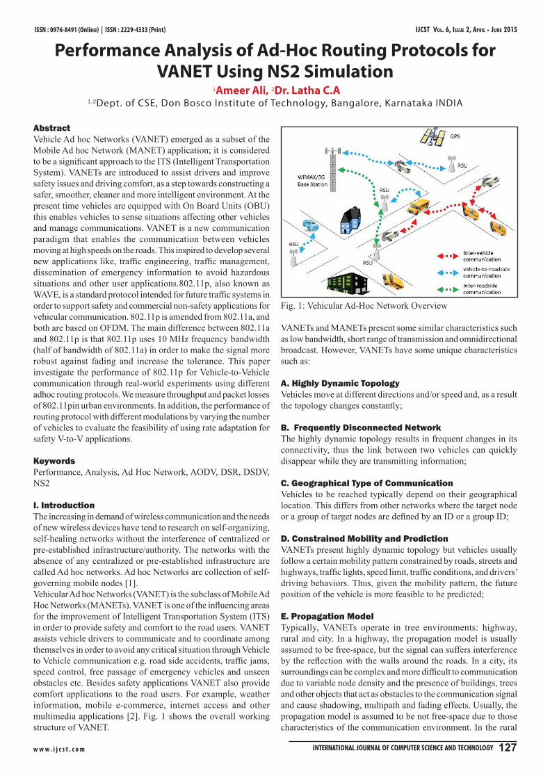
I. IntroductionThe increasing in demand of wireless communication and the needs of new wireless devices have tend to research on self-organizing, self-healing networks without the interference of centralized or pre-established infrastructure/authority. The networks with the absence of any centralized or pre-established infrastructure are called Ad hoc networks. Ad hoc Networks are collection of self-governing mobile nodes [1].Vehicular Ad hoc Networks (VANET) is the subclass of Mobile Ad Hoc Networks (MANETs). VANET is one of the influencing areas for the improvement of Intelligent Transportation System (ITS) in order to provide safety and comfort to the road users. VANET assists vehicle drivers to communicate and to coordinate among themselves in order to avoid any critical situation through Vehicle to Vehicle communication e.g. road side accidents, traffic jams, speed control, free passage of emergency vehicles and unseen obstacles etc. Besides safety applications VANET also provide comfort applications to the road users. For example, weather information, mobile e-commerce, internet access and other multimedia applications [2]. Fig. 1 shows the overall working structure of VANET.
Fig. 1: Vehicular Ad-Hoc Network Overview
VANETs and MANETs present some similar characteristics such as low bandwidth, short range of transmission and omnidirectional broadcast. However, VANETs have some unique characteristics such as:
A. Highly Dynamic TopologyVehicles move at different directions and/or speed and, as a result the topology changes constantly;
B. Frequently Disconnected NetworkThe highly dynamic topology results in frequent changes in its connectivity, thus the link between two vehicles can quickly disappear while they are transmitting information;
C. Geographical Type of CommunicationVehicles to be reached typically depend on their geographical location. This differs from other networks where the target node or a group of target nodes are defined by an ID or a group ID;
D. Constrained Mobility and PredictionVANETs present highly dynamic topology but vehicles usually follow a certain mobility pattern constrained by roads, streets and highways, traffic lights, speed limit, traffic conditions, and drivers’ driving behaviors. Thus, given the mobility pattern, the future position of the vehicle is more feasible to be predicted;
E. Propagation ModelTypically, VANETs operate in tree environments: highway, rural and city. In a highway, the propagation model is usually assumed to be free-space, but the signal can suffers interference by the reflection with the walls around the roads. In a city, its surroundings can be complex and more difficult to communication due to variable node density and the presence of buildings, trees and other objects that act as obstacles to the communication signal and cause shadowing, multipath and fading effects. Usually, the propagation model is assumed to be not free-space due to those characteristics of the communication environment. In the rural

IJCST Vol. 6, ISSue 2, AprIl - June 2015 ISSN : 0976-8491 (Online) | ISSN : 2229-4333 (Print)
w w w . i j c s t . c o m 128 InternatIonal Journal of Computer SCIenCe and teChnology
environments, due to the complex topographic forms (fields, hills, climbs, dense forests, etc.), it is important to consider the signal reflection and the attenuation on the signal propagation. Thus, in this scenario the free-space model is not appropriate. As in any other network, the propagation model in a VANET must consider the effects of potential interference of wireless communication from other vehicles and the existence of largely deployed access points.Several publications ([3-5]) have studied the performance of 802.11p, however they do not support realistic vehicular mobility simulation. In [6], the authors present a comprehensive evaluation and simulative review of the performance of 802.11p and WAVE standards. They use Qualnet network simulator for the simulation portion. In terms of modelling accuracy, A new model of IEEE 802.11 MAC and PHY, which support IEEE 802.11P, is designed and implemented in ns-2 network simulator version 2.34 [7]. This version of ns-2 network simulator is used for this paper [8].
The remainder of this paper is organized as follows. In section II we clarify the WAVE and IEEE802.11p structure.Different adhoc protocols are described in section III. The simulation scenario is conducted in section IV. Results from the simulation and the analyses of the performance metrics of the IEEE 802.11p are presented in section V. Finally, this paper is concluded in Section VI.
II. Overview of 802.11p ProtocolIn this section we briefly present an outline of WAVE architecture system and IEEE 802.11p protocol for VANET.
Fig. 2: DSRC Standards and Communication Stack
A. Physical and MAC LayersThe physical and MAC layers of WAVE are based on IEEE 802.11p standard. The physical layer of IEEE 802.11P consists of seven channels in 5.9GHz band which is similar to IEEE 802.11a design, but the main difference is that the IEEE 802.11p use 10MHZ bandwidth for each channel instead of 20MHZ bandwidth in IEEE 802.11a. The physical layer of 802.11p uses OFDM technology which is used for increasing data transmission rate and overcoming signal fading in wireless communication. One of the specifications of IEEE 802.11p is that the management functions are connected with the physical and MAC layers which are called physical layer management entity (PLME) and MAC layer management entity (MLME), respectively [3]. The IEEE 802.11p uses CSMA/CA to reduce collisions and provide fair access to the channel.
B. Multichannel OperationIEEE 1609.4 is one of the standards of the IEEE 1609 protocol family, which manages channel coordination and supports MAC service data unit delivery. This standard describes seven different channels with different features and usage (six service channels (SCH) and one control channel (CCH)). In addition, these channels use different frequencies and transmit powers. Eichler [3] mentions that each station continuously alternates between the control channel and one of the service channels; however the different channels cannot be used at the same time. According to [9], the control channel is used for system control and safety data transmission. On the other hand, non-safety messages are exchanged by the six service channels. The IEEE 802.11p MAC layer is based on multichannel operation of WAVE architecture and 802.11e EDCA. This mechanism defines four different access categorizes (AC) for each channel. The access categories are indicated by AC0-AC3, and each of them has an independent queue [3]. The EDCA mechanism provides prioritization by assigning different contention parameters to each access category. AC3 has the highest priority to access medium, and AC0 has the lowest priority. So there are six service channels and one control channel and each of them has four different access categories. Consequently, during data transmission, there are two contention procedures to access the medium:
Internal contention procedure which occurs inside each • channel between their access categories by using the contention parameters (Arbitrary InterFrame space (AIFS) and Contention Window (CW)),The contention procedure between channels to access the • medium is supported by different timer settings based on the internal contention procedure.
Throughout data transmission, each frame is categorized into different access categories, depending on the importance of the message. Then the selected frames contend to access the medium using their contention parameters [10].
Logical link control (LLC) is another element of WAVE structure which is similar to upper sub-layer of OSI layer two. LLC provides the communication between upper layers and the lower layer.
C. Network and transport layersThe IEEE 1609.3 defines the operation of services at network and transport layers. Moreover, it provides wireless connectivity between vehicles, and vehicles to roadside devices. The functions of the WAVE network services can be separated to two sets:
Data-plane services: they transmit network traffics and • support IPV6 and WSMP protocols. WAVE short-message-Protocol (WSMP) provides this capability that applications can send short message to increase theprobability of receiving the messages in time.Management-plane services: Their functions are to configure • and maintain system, for instance: IPV6 configuration, channel usage monitoring, and application registration. This service is known as WAVE management entity (WME).
The devices which use WAVE architecture should implement UDP as specified in RFC 768, and TCP as defined in RFC 793 [10].
D. Resource ManagerThere are two kinds of wireless access in VANETs:
Roadside unit (RSU) which are the static stations located •
IJCST Vol. 6, ISSue 2, AprIl - June 2015
w w w . i j c s t . c o m InternatIonal Journal of Computer SCIenCe and teChnology 129
ISSN : 0976-8491 (Online) | ISSN : 2229-4333 (Print)
along the roadside,On-board unit (OBU) mounted on a vehicle and can operate • while moving.
IEEE 1609.1 standard defines a WAVE application known as resource manager (RM) which should allow communication between applications runs on RSUs and OBUs. The RM resides on either OBUs or RSUs [10].
E. Security ServicesThe IEEE 1609.2 standard defines security services for the WAVE architecture and the applications which run through this architecture. This standard defines the format and the processing of secure messages; furthermore, it describes the core security functions [11].
III. Vanet Routing ProtocolWireless networks can be classified in two types:
A. Infrastructure NetworksInfrastructure network consists of a network with fixed and wired gateways. A mobile host communicates with a bridge in the network (called base station) within its communication radius. The mobile unit can move geographically while it is communicating. When it goes out of range of one base station, it connects with new base station and starts communicating through it. This is called handoff. In this approach the base stations are fixed.
B. Infrastructure Less (Ad-hoc) NetworksIn ad hoc networks [14] all nodes are mobile and can be connected dynamically in an arbitrary manner. As the range of each host’s wireless transmission is limited, so to communicate with hosts outside its transmission range, a host needs to enlist the aid of its nearby hosts in forwarding packets to the destination. So all nodes of these networks behave as routers and take part in discovery and maintenance of routes to other nodes in the network. Ad hoc Networks are very useful in emergency search-and-rescue operations, meetings or conventions in which persons wish to quickly share information, and dataacquisition operations in inhospitable terrain. This ad-hoc routing protocols can be divided into two categories:
1. Table-Driven Routing ProtocolsIn table driven routingprotocols, consistent and up-t o-date routing information to all nodes is maintained at each n ode.
2. On-Demand Routing ProtocolsIn On-Demand routingprotocols, the routes are created as and when required. When a source wants to send to a destination, it invokes the route discovery mechanisms to find the path to the destination
B. Ad-Hoc Routing Protocols Description
1. Destination -Sequenced Distance -VectorThe Destination-Sequenced Distance-Vector (DSDV) [12] Routing Algorithm is based on the idea of the classical Bellman-Ford Routing Algorithm with certain improvements. Every mobile station maintains a routing table that lists all available destinations, the number of hops to reach the destination and the sequence number assigned by the destination node. The sequence number is used to distinguish stale routes from new ones and thus avoid the
formation of loops. The stations periodically transmit their routing tables to their immediate neighbors. A station also transmits its routing table if a significant change has occurred in its table from the last update sent. So, the update is both time-driven and event-driven.The routing table updates can be sent in two ways: a “full dump” or an incremental update. A full dump sends the full routing table to the neighbors and could span many packets whereas in an incremental update only those entries from the routing table are sent that has a metric change since the last update and it must fit in a packet. If there is space in the incremental update packet then those entries may be included whose sequence number has changed. When the network is relatively stable, incremental updates are sent to avoid extra traffic and full dump are relatively infrequent. In a fast-changing network, incremental packets can grow big so full dumps will be more frequent.
2. Ad Hoc on -Demand Distance Vector Routing (AODV)AODV [11] discovers routes on an as needed basis via a similar route discovery process. However, AODV adopts a very different mechanism to maintain routing information. It uses traditional routing tables, one entry per destination. This is in contrast to DSR, which can maintain multiple route cache entries for each destination. Without source routing, AODV relies on routing table entries to propagate an RREP back to the source and, subsequently, to route data packets to the destination. AODV uses sequence numbers maintained at each destination to determine freshness of routing information and to prevent routing loops. All routing packets carry these sequence numbers.
An important feature of AODV is the maintenance of timer -based states in each node, regarding utilization of individual routing table entries. A routing table entry is expired if not used recently. A set of predecessor nodes is maintained for each routing table entry, indicating the set of neighboring nodes which use that entry to route data packets. These nodes are notified with RERR packets when the next -hop link breaks. Each predecessor node, in turn, forwards the RERR to its own set of predecessors, thus effectively erasing all routes using the broken link. In contrast to DSR, RERR packets in AODV are intended to inform all sources using a link when a failure occurs. Route error propagation in AODV can be visualized conceptually as a tree whose root is the node at the point of failure and all sources using the failed link as the leaves.
3. Dynamic Source Routing (DSR)The key distinguishing feature of DSR [13] is the use of source routing. That is, the sender knows the complete hop - by-hop route to the destination. These routes are stored in a route cache. The data packets carry the source route in the packet header. When a node in the ad hoc network attempts to send a data packet to a destination for which it does not already know the route, it uses a route discovery process to dynamically determine such a route. Route discovery works by flooding the network with route request (RREQ) packets. Each node receiving an RREQ rebroadcasts it, unless it is the destination or it has a route to the destination in its route cache. Such a node replies to the RREQ with a route reply (RREP) packet that is routed back to the original source. RREQ and RREP packets are also source routed. The RREQ builds up the path traversed across the network. The RREP routes itself back to the source by traversing this path backward. The route carried back by the RREP packet is cached at the source for future use. If any link on a source route is broken, the source node is notified

IJCST Vol. 6, ISSue 2, AprIl - June 2015 ISSN : 0976-8491 (Online) | ISSN : 2229-4333 (Print)
w w w . i j c s t . c o m 130 InternatIonal Journal of Computer SCIenCe and teChnology
using a route error (RERR) packet. The source removes any route using this link from its cache. A new route discovery process must be initiated by the source if this route is still needed. DSR makes very aggressive use of source routing and route caching.
IV. SimulationsThe simulation model is based on NS 2 simulation version 2.34. The simulation scenario is designed according to the normal state of car running on a road. The position and the movement of the nodes are given in the screen scenario generator file shown in Table 1. The routing parameters are obtained from the trace file. To evaluate the performance of the routing protocols, some parameters have been used in the TCL file for measuring the efficiency of vehicle-to-vehicle communication. The studies of these parameters are analyzed by the NS 2 Trace file. Therefore the Agent Trace ON and Route Trace ON in the TCL file are activated. The speed of the vehicles is assumed to be constant at 40kmph. An IEEE working group has invented a new PHY/MAC layer amendment of the 802.11p standard, which is designed for car-to-car and car-to-infrastructure communication only.The critical parameters used in the NS 2.34 version simulation is given in below table:
Table 1: Parameters for NS 2.34Network Area 600m x 300mRadio Range 200m
Traffic Type CBR
Visualization Tool Nam, TraceDuration 200 seconds
MAC Layer 802.11p,802.11Protocol AODV,DSDV,DSR
Number of nodes 8,16,32,48,64Speed 40Kmph
We have used the above mentioned parameters and estimated the performance of the Routing protocols such as DSDV, AODV and DSR for vehicular communication.
IEEE 802.11p Parameters in TCL file are given in the below Table 2
Table 2: Parameters of IEEE 802.11p
We compare the Packet delivery ratio, Packet drop, Average Throughput and Network routing load with 802.11p standards
for Urban VANET model for different routing protocols. For reliability, seed values are given for 5 different simulation which are used to find the values and the average is considered. The performance of different routing protocol using 802.11p standard are studied based on the performance metrics.
V. Simulated resultsFor all the simulations, the same movement models were used, the number of traffic sources wasvaried from 4, 8, 16, 24, 32 and maximum speed of the nodes was set to 40kmph and the number of nodes was varied as 8, 16, 32, 48 and 64.
A. Packet Delivery Ratio(PDR)Vs Number of NodesThe performance of various routing protocols such as AODV, DSDV and DSR in terms of packet delivery ratio to the number of nodes is shown below in figure 3 and values obtained are given in Table 3.
Table 3:
NODES AODV DSDV DSR8 80.218 67.94 71.763816 75.1415 63.5137 59.991332 76.0607 54.456 52.440248 76.0572 53.34 50.842364 77.6726 52.2667 51.015
Fig. 3: Packet Delivery Ratio (PDR) Vs Number of Nodes
Fig. 3 shows the average PDR of all 3 protocols. The behavior of PDR of every routing protocol with respect to number of nodes is shown. We observe that AODV routing protocol in all the conditions provides better PDR consistently at the initial stage the PDR is 80.2% and it is better compared to other protocols. AODV out performed both DSDV and DSR protocols by 9.73% and 10.3% respectively, As the number of nodes increases DSR routing protocol’s PDR gradually decreases. The proactive routing protocols have decreasing PDR all times. It is observed that proactive routing protocols with short interval values provide better PDR, as their routing table is updated quickly and reactive protocol such as AODV performs better in all scenarios.
B. Throughput Vs Number of Nodes:The performance of various routing protocols such as AODV, DSDV and DSR in terms of throughput to the number of nodes is shown below fig. 4 and values obtained are in Table 4.

IJCST Vol. 6, ISSue 2, AprIl - June 2015
w w w . i j c s t . c o m InternatIonal Journal of Computer SCIenCe and teChnology 131
ISSN : 0976-8491 (Online) | ISSN : 2229-4333 (Print)
Table 4: Throughput in 802.11pNODES AODV DSDV DSR
8 634.27 775.44 508.0716 553.4 613.29 310.3432 474.88 354.22 111.2648 511.83 331.01 97.0164 484.15 327.71 63.27
Fig. 4: Throughput Vs Number of Nodes
Fig. 4 shows the average Throughput of all 3 protocols. The behavior of Throughput of every routing protocol with respect to number of nodes is shown. We observe that AODV routing protocol with increased number of vehicles is able to give the better Throughput as compared to other protocols. As the number of nodes increases AODV routing protocol with throughput 43.23% outperforms DSR with throughput 39.05%. Throughout the simulations it is observed that DSDV has lesser throughput (17.72%). The reactive routing protocols have better Throughput at all the time.
C. Normalized Routing Load Vs Number of NodesThe performance of various routing protocols such as AODV, DSDV and DSR in terms of network routing load to the number of nodes is shown below in fig. 5 and values are updated in Table 5.
Table 5: NRL in 802.11PNODES AODV DSDV DSR
8 0.1233 0.0461 0.180716 0.1157 0.0884 0.280532 0.0905 0.1026 0.292148 0.0806 0.0932 0.240864 0.0734 0.0806 0.2003
Fig. 5: Normalized Routing Load Vs Number of Nodes
Fig. 5 shows the Normalized Routing Load (NRL). It is observed that DSDV consistently has more NRL (19.67%) compared to reactive protocols. This is because the proactive routing protocols generate sustained control traffic, in order to have updated information about the topology and routing paths. This process is done irrespective of user communication. On one hand this helps in avoiding initial latency of finding routes, but in return it generates more routing overhead compared to reactive routing protocols. It is observed that AODV has less routing overhead (23.15%) compared to DSDV with NLR% as 19.67.
D. Packet Drop Vs Number of NodesThe Packet Drop of various routing protocols such as AODV, DSDV and DSR in terms of packet drop to the number of nodes is shown below in fig. 6 and Table 6.
Table 6: Packet Drop in 802.11pNODES AODV DSDV DSR
8 140898 133762 15970016 221857 224381 25105232 471256 516670 50331948 666248 693142 70130564 843936 904270 877456
Fig. 6: Packet Drop Vs Number of Nodes
Fig. 6 shows the average Packet Drop of all 3 protocols. The behavior of Packet Drops of every routing protocol with respect to number of nodes is shown. We observe that DSR routing protocol in dense condition have lesser Packet Drop, as compared to other protocols. As the number of nodes increases DSR routing protocol’s Packet Drop is increased and AODV routing protocol with Packet drop, 32.07% outperforms DSR and DSDV with 34.11% and 33.82% respectively. The proactive routing protocols have increasing Packet Drops at all times. It is observed that reactive routing protocol i.e., AODV provides lesser Packet Drop and outperforms other routing protocols.
VI. ConclusionIn this paper, we compared the performance of DSDV, AODV and DSR routing protocols for ad hoc networks using ns-2 presents the study of an efficient routing protocol for vehicular communication in city environment. The earlier VANET models discussed only the communication between vehicles through the RSU. Most of the researchers used standard 802.11 for VANET model with the movements of mobile nodes within the city area.

IJCST Vol. 6, ISSue 2, AprIl - June 2015 ISSN : 0976-8491 (Online) | ISSN : 2229-4333 (Print)
w w w . i j c s t . c o m 132 InternatIonal Journal of Computer SCIenCe and teChnology
For efficient data communication the protocol used in the given model is important. Thus the familiar routing protocols are compared with each other and it is concluded that the reactive routing protocols i.e. AODV with IEEE 802.11p yields better performance.
References[1] M. Mauve, A. Widmer, H. Hartenstein,“A survey on position-
based routing in mobile Ad-Hoc networks”, Network, IEEE, Vol. 15, No. 6, pp. 30 - 39, Nov/Dec 2001.
[2] Bernsen, J. Manivannan, D.,“Routing Protocols for Vehicular Ad-Hoc Networks That Ensure Quality of Service”, In the fourth international conference on Wireless and Mobile Communications., pp. 1-6, Aug. 2008.
[3] S. Eichler,“Performance evaluation of the IEEE 802.11p WAVE communication standard”, In Proc. IEEE Vehicular Technology Conf., Baltimore, MD, US, Oct. 2007, pp. 2199-2203.
[4] T. Murray, M. Cojocari, H. Fu,"Measuring the performance of IEEE 802.11p using ns-2 simulator for vehicular networks", In: Proc. IEEE EIT, 2008, pp. 98–503.
[5] K. Bilstrup, E. Uhlemann, E. G. Ström, U. Bilstrup, "Evaluation of the IEEE 802.11p MAC method for vehicle-to-vehicle communication”, Proc. IEEE Int. Symposium on Wireless Vehicular Communications, Calgary, Canada, Sept. 2008.
[6] S. Grafling, P. Mahonen, J. Riihijarvi,“Performance evaluation of IEEE 1609 WAVE and IEEE 802.11p for vehicular communications”, In Proceedings of the 2nd International Conference on Ubiquitous and Future Networks (ICUFN ’10), June 2010, pp. 344 –348.
[7] Q. Chen, F. Schmidt-Eisenlohr, D. Jiang, M. Torrent- Moreno, L. Delgrossi, H. Hartenstein,“Overhaul of IEEE 802.11 modeling and simulation in NS-2”, In Proc. of the 10th ACM/IEEE International Symposium on Modeling, Analysis and Simulation of Wireless and Mobile Systems (MSWiM), 2007.
[8] “Network Simulator ns-2”, [Online] Available: http://www.isi.edu/nsnam/ns/IEEE Wireless Communications, Vol. 13, No. 5, pp. 36–43, Oct. 2006.
[9] M. Amadeo, et al.,“Enhancing IEEE 802.11p/WAVE to provide infotainment applications in VANETs”, Ad-Hoc Networks. S.1.: Elsevier, 2010.
[10] WILLIAMS, B.,"Intelligent Transport Systems Standards", Artech House Publishers, 2008.
[11] R. A. Uzcátegui, G. Acosta-Marum,“WAVE: A Tutorial”, IEEE Commun. Mag., May 2009.
[12] Ian D. Chakeres, Elizabeth M. Belding-Royer,"AODV Routing Protocol Implementation Design".
[13] Charle E. Perkins, Pravin Bhagwat,"Highly Dynamic Destination - Sequenced Distance- Vector Routing (DSDV) for Mobile Computers.
[14] David B. Johnson, David A. Maltz, Josh Broch,"DSR: The Dynamic Source Routing protocol for Multi-Hop Wireless Ad-Hoc networks".
Mr. AMEER ALI received his Bachelor’s Degree in Computer Science and Engineering from Ghousia College of engineering affiliated to Visvesvaraya Technological University, Belgaum in the year 2013.He is currently pursuing Master’s Degree in Computer Science and Engineering from Don Bosco Institute of Technology,Bangalore affiliated to Visvesvaraya Technological University, Belgaum. Project is
carried out in Indian Institute of Science (IISc) Bangalore under the guidance of Dr. R. Bhakthavathsalam, Principal Research Scientist, SERC Dept., IIsc.
Dr. LATHA C A is a doctorate from Anna University Chennai, India, in the domain of distributed systems. She has graduated in the year 1991 from Mysore University, post graduated from National Institute of Technology Karnataka in 2003. She has a teaching experience of more than 20 years and research experience of more than 7 years. As a result, she has in her credit several national and international
papers. She has also filed for a patent at USPTO for one of her research works. Her area of interest includes, Distributed Systems and Cloud Computing. At present she is serving as Professor and Head in the department of Computer Science and Engineering at Don Bosco Institute of Technology, Bangalore affiliated to Visweswaraya Technological University, India.