Embed Size (px)
Citation preview

Perceptual audio coding
Nicola OrioDipartimento di Ingegneria dell’Informazione
IV Scuola estiva AISV, 8-12 settembre 2008

2
Introduction
Current and future visual communications for applications such asbroadcastingstoragevideotelephonyvideo- and audiographic-conferencingnews gathering servicesinteractive multimedia (information, training, entertainment)services assume a substantial audio component.
Even text, graphics, fax, still images, email documents, etc. will gainfrom voice annotation and audio clips.

3
Motivations
Main motivations for low bit rate coding:need to minimize transmission costs or provide cost efficientstoragedemand to transmit over channels of limited capacity such asmobile radio channelsneed to support variable-rate coding in packet-oriented networksneed to share capacity for different services (voice, audio, data,graphics, images) in integrated service network

4
Quality Sampling Rate(KHz) Bits per Sample
Data RateKbits/s Kbytes/s
Data Size in1 minute1 hour
Telephone 8 8 (Mono)64Kbps
8480KB28.8MB
AM Radio 11.025 8 (Mono)88.2Kbps
11.0660KB39.6MB
FM Radio 22.050 16 (Stereo)705.6Kbps
88.25.3MB
317.5MB
CD 44.1 16 (Stereo)1.41Mbps
176.410.6MB635MB
Conclusion need advanced coding for compressing sound data
PCM Audio Data Rate and Data Size

5
Basic requirements
High quality of the reconstructed signal with robustnessto variations in spectra and levelsrandom and bursty channel bit errors
Low complexity and power consumption of the codecsmore constraints on decoders than on encoders
Additional network-related requirements:low encoder/decoder delaysrobust tandeming of codecs, transcodabilitya graceful degradation of quality with increasing bit error rates(mobile radio and broadcast applications)
Coded bit streams must allowediting, fading, mixing, and dynamic range compression
Synchronization between audio and video bitstreams

6
First proposals to reduce wideband audio coding rates havefollowed those for speech codingSpeech and audio are still quite different and audio has
higher sampling ratebetter amplitude resolutionhigher dynamic rangelarger variations in power density spectradifferences in human perceptionhigher listener expectation of qualitystereo and multichannel audio signal presentations
Speech can be coded very efficiently because a speech productionmodel is available
nothing similar exists for audio signals.
Wideband audio vs. Speech

7
Evolution of audio coding
Rapid progress in source codinglinear predictionsubband codingtransform codingvector quantizationentropy coding
Currently good coding quality can obtained with bit rates of1 bit/sample for speech2 bits/sample for audio
Expectations over the next decade0.5 bit/sample for speech1 bits/sample for audio

8
Quality measures – 1
Digital representations of analog waveforms cause some kind ofdistortion which can be specified
by subjective criteria as mean opinion score (MOS) as ameasure of perceptual similarityby simple objective criteria (i.e. SNR) as a measure of waveformsimilarity between source and reconstructed signalby objective measures of perceptual similarity which take intoaccount facts about human auditory perception.
Mean opinion score (MOS)subjects classify the quality of coders on an N-point quality scalethe final result is an averaged judgment called MOStwo five-point adjectival grading scales are in use, one for signalquality, and the other one for signal impairment, and anassociated numbering

9
Quality measures – 2
MOS advantagesdifferent impairment factors can be assessed simultaneouslyeven small impairments can be graded
MOS disadvantagesMOS value vary with time and listener panel to listener paneldifficult to duplicate test results at a different test sitein the case of audio signals, MOS values depend strongly on theselected test items
ISO/MPEG teststhree signals A,B,C; A is unprocessed source, B and C are thereference and the system under testthe selection B/C is double blindsubjects have to decide if B or C is the reference and have tograde the remaining one

Audio coding
Perception

11
Perception : Frequency representation
The inner ear performs short-term analyses where frequency-to-placetransformations occur along the basilar membrane
two sounds with different waveforms but same frequencycomponents are perceived almost identical
sound 1
sound 2
samespectrum

12
Perception : Fourier analysis
Fourier analysis is a useful tool for sound processingphase information is not as perceptually important as amplitude

13
Perception : Critical bands – 1
The power spectra are not presented on a linear frequency scalebut on limited frequency bands called critical bands.
Rough description as a filterbank of bandpass filters withbandwidths that increase with the center frequency.

14
Perception : Critical bands – 2
band center bounds
1 50 -100
2 150 100-200
3 250 200-300
…
7 700 630-770
…
11 1370 1270-1480
…
15 2500 2320-2700
…
19 4800 4400-5300
20 5800 5300-6400
…
25 19500 15500-
Strong perceptual interferencebetween frequencies in the samecritical bands
Explanation: it looks thatcritical bands are related tosections of the acoustic nerve
The scale related to critical bandsis called bark scale
Bandwidth of about 100 Hz below~500 HzBandwith increase of about 20%above ~500 Hz

15
Perception : Hearing limitations – 1
Frequencies < 16-20 Hz and > 16-20 kHz are not perceivedAmplitudes below a given threshold are not perceived
the threshold depends on the frequency

16
Perception : Hearing limitations – 2
Perceived intensity depends also on frequencydynamic range (quitest to loudest) is about 100 dB
17
Perception : Masking – 1
Simultaneous masking is a frequency domain phenomenon wherea low-level signal (the maskee) can be made inaudible by asimultaneously occurring stronger signal (the masker)
masker and maskee should have close enough frequenciesThe masking threshold, in the context of source coding also knownas threshold of just noticeable distortion (JND), varies with time. Itdepeds on
the sound pressure level (SPL),the frequency of masker,the characteristics of masker and maskee
Without masker, a signal is inaudible if its sound pressure level isbelow the threshold of audibility anywayThe distance between the level of the masker and the maskingthreshold is called signal-to-mask ratio (SMR).

18
Perception : Masking – 2

19
Perception : Masking – 3
Different masking effects appear when masking and maskee aretones or noise
tone masking noise => strongnoise masking tone => weak
Simultaneous masking changes with frequency
20
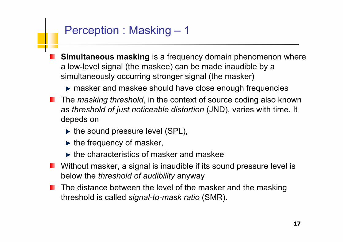
Perception : Masking – 4
Masking effect is strictly related to the presence of critical bandsa weak stimulus is not perceived when a strong one excites thesame perceptors
almost constant in bark scale

21
Perception : Masking – 5
maskingtone
maskingthreshold
minimum maskingthreshold
criticalband
nextband
m-1 bitm bitm+1 bit
SMR
NMR
SNR
dB
frequency
SNR = SMR (Signal to Mask Ratio) + NMR (Noise to Mask Ratio)

22
Perception : Temporal masking
Temporal masking may occur when two sounds appear within asmall interval of time.
a stronger sound may mask the weaker one, even if the maskeeprecedes the masker (pre- and post masking )

23
Perception : Global masking
Simultaneous and temporal masking are combined togethereffect is on the frequency axis, andhas influence on the temporal axis

24
Perception : Source localization
Sound perception has some of limitations related to the sourcelocalization
stereo signals (or more)Low frequencies:
impossible to localize the audio source, mono is enoughHigh frequencies:
localization is based on amplitude envelope only
In general, for stereo signals there may beinterchannel dependenciesinterchannel masking effectsstereo-irrelevant components of the multichannel signal

Perceptual audio coding
Fundamentals

26
Compression & Quantization
How big is audio data? What is the bitrate?Fs frames/second (e.g. 8000 or 44100)xC samples/frame (e.g. 1 or 2 channels)xB bits/sample (e.g. 8 or 16)Fs ·C·B bits/second (e.g. 64 Kbps or 1.4 Mbps)
How to reduce?lower sampling rate less bandwidth (muffled)lower channel count no stereo imagelower sample size quantization noise
Or: use data compression

27
Data compression: Redundancy vs. Irrelevance
Two main principles in compression:remove redundant informationremove irrelevant information
Redundant info is implicit in remaindere.g. signal bandlimited to 20kHz, but sample at 80kHz can recover every other sample by interpolation:
Irrelevant info is unique but unnecessarye.g. recording a microphone signal at 80 kHz sampling rate

28
Irrelevant data in audio coding
For coding of audio signals, irrelevant means perceptuallyinsignificant
an empirical propertyCompact Disc standard is adequate:
44 kHz sampling for 20 kHz bandwidth16 bit linear samples for ~ 96 dB peak SNR
Reflect limits of human sensitivity:20 kHz bandwidth, 100 dB intensitysinusoid phase, detail of noise structuredynamic properties - hard to characterize
Problem: separating salient & irrelevant

29
Quantization
Represent waveform with discrete levelsEquivalent to adding error e[n]:
e[n] ~ uncorrelated, uniform white noise

30
Linear Pulse Code Modulator (PCM)
A simple source coder contains sampler, quantizer, and a mapper
SamplerUniform
QuantizerSymbol-to-bit
mapper( )tx ( )tx
s( )txsˆ 0,0,0,1,0,1,1,0
( )tx
t
( )txs
tsT
sT2
sT3
3.0
9.0
8.1
( )txsˆ
tsT
sT2
sT3
0.1
0.2
tsT
sT2
sT3
0.1

31
Linear PCM Decoding
A process to undo the effects of speech codingLocate at the receiverLinear PCM
SamplerUniform
QuantizerSymbol-to-bit
mapper( )tx ( )tx
s( )txsˆ 0,0,0,1,0,1,1,0
PCM coder
Low-passfilter
Bit-to-symbolmapper
( )txsˆ0,0,0,1,0,1,1,0
PCM decoder

32
Quantization noise (Q-noise)
Uncorrelated noise has flat spectrumWith a B bit word and a quantization step D

33
Non-Uniform Quantization
Used to transmit in ISDN8 kHz, 8 bits: 64kbps
Logarithmic quantizationdynamic range as 13/14 linear bits16 bits are compressed with a non linear technique in 8 bitssamples
( )( )
( )( )
127128 ln 1 , 0
ln 1
127127 ln 1 , 0
ln 1
x x
y
x x
µµ
µµ
!+ • + "# +
##= $## % • + &
+#'

34
µ=0
µ=5
µ=15
µ=40
µ=100
µ=255
( )nx
( )nx̂
µ-law Compression – 1
( )( )
( ).sgn1log
1log
e
max
max xx
x
GxG
e
µ
µ
+
!!"
#$$%
&+
= ( )!"#
<$
%=
=
0 if ,1
0 if ,1 sgn
255 typically,
x
xx
µ

35
µ-law Compression – 2

Perceptual audio coding
Techniques

37
Principles in low bit rate coding – 1
Digital coding at high bit rates is dominantly waveform-preserving,i.e., the amplitude-versus-time waveform of the decoded signalapproximates that of the input signal.
the basic error criterion of codec design is the difference signalbetween input and output waveform
At lower bit rates, facts about the production and perception ofaudio signals have to be included in coder design.
the error criterion has to be in favor of an output signal that isuseful to human receiver rather than favoring an output signalthat follows and preserves the input waveform
Basically, an efficient source coding algorithm willremove redundant components of source signal by exploitingcorrelations between its samplesremove components which are irrelevant to the ear.

38
Principles in low bit rate coding – 2
The dependence of auditory perception on frequency and theperceptual tolerance of errors can directly influence encoderdesigns
noise-shaping techniques can shift coding noise to frequencybands where that noise is not of perceptual importancethe noise shifting must be dynamically adapted to the actualshort-term spectrum in accordance with the signal-to-mask ratio
the encoding process is controlled by the signal-to-mask ratioversus frequency curve from which the needed amplitude resolutionin each critical band is derived
the bit allocation and rate in each critical band can be computedGiven the bitrate for a complete masking distortion
the coding scheme will be perceptually transparentthe decoded signal is subjectively indistinguishable from areference.

39
Principles in low bit rate coding – 3
if the necessary bit rate for a completely masking of distortions is notpossible,
the global masking threshold serves as a weighting function forspectral errorthe resulting error spectrum will have the shape of the globalmasking threshold
we cannot go to limits of masking or just noticeable distortionbecause
postprocessing may (e.g. filtering in equalizers) demask thenoise,our current knowledge about auditory masking is very limited=> safety margin needed

40
Frequency domain coders
The short-term spectral characteristics of the signal and themasking properties of the ear are exploited to reduce bitrate
Direct method for noise-shaping and suppression of frequencycomponents that not need to be transmitted.Source spectrum is split into frequency bandsEach frequency component is quantized separately=> quantization noise associated with a particular band iscontained within that band.
The number of bits used to encode frequency components varies.component being subjectively more important are quantizedmore finely, i.e. more bit allocated
A dynamic bit allocation controlled by the spectral short-termenvelope of the source signal is needed.
information transmitted to the decoder as side information

41
Subband coding – 1
The source signal is fed into an analysis filter bank consisting of Mbandpass filters which are contiguous in frequency so that the set ofsubband signals can be recombined additively to produce theoriginal signal or a close version thereof.Each filter output is critically decimated (i.e. sampled at twice thenominal bandwitdth) by a factor equal to M.=> an aggregate number of subband samples that equals that in thesource signalEach decimated filter output is quantized separately.In the receiver, the sampling rate of each subband is increased tothat of the source signal by filling in the appropriate number of zerossamples.Interpolated subband signals appear at the bandpass outputs of thesynthesis filter bank.

42
Subband coding – 2
Quantize separately in different bandsquantization noise stay within band; gets masked
Critical sampling: 1/M of spectrum per bandaliasing inevitableQuadrature Mirror Filters: cancel with alias of adjacent bands

43
Polyphase Filter Bank – 1
CharacteristicsLossy (even without quantization)Fairly simple with reasonable resolution
What It Does:Divides input signal into equal width sub-bands.Sub-bands overlap a lot, introduces error for analyzing.
MP3 SpecificInput signal size is 32 samples which produces 32 sub-bands.Vital part of Layers 1,2,3Examples of subband coding
ISO/MPEG Audio Coding, Layers I and II

44
Polyphase Filter Bank – 2

45
Pre-echoes – 1
Crucial part in frequency domain coding of audio signals is theappearance of pre-echoes.
for example, a silent period is followed be a percussive sound,such as from castanets or triangles, within the same codingblock=> comparably large instantaneous quantization errors=> pre-echoes can become distinctively audible, especially atlow at low bit rates with comparably high error contributionspre-echoes can be masked by the time domain effect of pre-masking if the time spread is of short length (in the order of afew milliseconds)=> pre-echoes can be avoided by using blocks of short lengths.However, a larger percentage of the total bit rate is required forthe transmission of side information if the blocks are too short.a solution to this problem is to switch between block sizes ofdifferent lengths

46
Pre-echoes – 2
original signal
pre-echo(audible)
pre-echo(non audible)

47
Transform coding
A block of input samples is linearly transformed via a discretetransform into a set of transform coefficients.These coefficients are then quantized and transmitted in digital formto the decoder.In the decoder an inverse transform maps the signal back into thetime domain.Typical transforms are the discrete Fourier Transform (DFT) or thediscrete cosine transform (DCT), calculated via FFT, and modifiedversions thereof.Discrete transforms can be viewed as filter banks. The finite lengthsof its bandpass impulse responses may be so-called blockboundary effects.=> State-of-the-art coders employ a modified DCT (MDCT) withoverlapping analysis blocks which can essentially eliminate theseeffects.

48
Modified Discrete Cosine Transform
Characteristicslossless, when there is no quantizationcomplex with good resolutionoptimized for audio
What it doesdivides output of PQF into 18 subbands per input subband
32 x 18 = 576 subbandsattempt to correct some error from PQF’s subband overlapping
MDCT transform splits each subband sequence further in frequencycontent to achieve a high frequency resolution.
It is specific for MP3 (MPEG1 – Layer III)

49
Discrete Cosine Transform
DCT
Ck = impulse responseh = low pass prototype filterM = num. of bandk = the order of the filter
h(n) is restricted to a rectangular window of length M
)]2
1)((cos[
2)12()( 0
+++!!=M
nkkMM
nMhnCk
"
!"
!#$
%%=
otherwisefor 02
3
2
Mfor 1
)(
Mn
nhdct

50
Modified Discrete Cosine Transform
MDCTh(n) has a longer length
Reduces the spectral leakage between channels by overlapping 50%
Hybrid (Subband/Transform) CodingCombinations of discrete transform and filter bank implementationsDifferent frequency resolutions can be provided at differentfrequencies in flexible way by using a cascade of a filterbank (with itsshort delays) and a linear MDCT transform (hybrid filterbank).
MDCT transform splits each subband sequence further infrequency content to achieve a high frequency resolution.
1-0..2Mnfor )]5.0(2
sin[)( =+= nM
nhMDCT
!

51
Windowing and overlapping
Long window Short window Stop windowStart windowMDCT analyzes data in blocks of length 18 or 6 samples.
This is 26 and 12 samples taking into account 50% overlapping.Overlapping reduces inconsistencies and misalignment betweencompressed sections.Supports mixed usage of small and large blocks
Provides better frequency resolution where it is neededMixes require transition blocks.

Perceptual audio coding
Additional techniques

53
Joint stereo
The correlation between left and right channels is exploited tofurther reduce overall bitrate
For low frequencies: impossible to identify source positionmono is enough
For high frequencies: the identification of source position isbased on amplitude envelope
mono spectrumtwo modulations for amplitudes

54
Redundant information
Redundancy removal is losslessSignal correlation implies redundant information
Problem: separating unique & redundant

55
Optimal coding
Shannon information:An unlikely occurrence is more ‘informative’
Opt. bitrate token length = entropy H = E[I]i.e. equal-length tokens are equally likely
How to achieve this?transform signal to have uniform pdfnonuniform quantization for equiprobable tokensvariable-length tokens Huffman coding
56
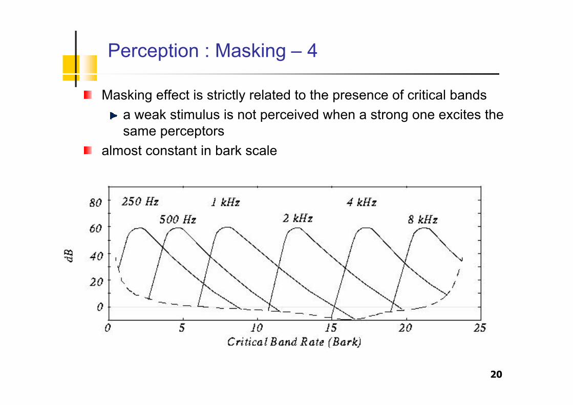
Quantization for optimum bitrate
Quantization should reflect pdf of signal:
Or, codeword length per Shannon –log2(p(x)):

57
Huffman coding
Variable-length bit sequence tokens→ can code unequally probable events
Tree-structure for unambiguous decoding:
Can build tables to approximate arbitrary distributionsEliminates irrelevance .. within limitsProblem: very probable events short tokens

58
Bit reservoir
Problem:A frame with little audio interest may require few bits to encode
with a constant bitrate these bits may be unusedA frame with substantial audio interest may require more bits toencode
with a constant bitrate the audio quality may decreaseSolution:
Allow frames to give to or take from a reservoirEach frame that save spaces, allows subsequent frames to storebits if needed
typical situation of a silence (few bits) followed by an attack(many bits)