Embed Size (px)
Citation preview

1
Per-Relay Power Minimization for Multi-userMulti-channel Cooperative Relay Beamforming
Ali Ramezani-Kebrya, Min Dong, Ben Liang, Gary Boudreau, and Ronald Casselman
Abstract—We investigate the optimal relay beamforming prob-lem for multi-user peer-to-peer communication with amplify-and-forward relaying in a multichannel system. Assuming eachsource-destination (S-D) pair is assigned an orthogonal channel,we formulate the problem as a min-max per-relay power mini-mization problem with minimum signal-to-noise (SNR) guaran-tees. After showing that strong Lagrange duality holds for thisnon-convex problem, we transform its Lagrange dual problemto a semi-definite programming problem and obtain the optimalrelay beamforming vectors. We identify that the optimal solutioncan be obtained in three cases, depending on the values ofthe optimal dual variables. These cases correspond to whetherthe minimum SNR requirement at each S-D pair is met withequality, and whether the power consumption at a relay is themaximum among relays at optimality. We obtain a semi-closedform solution structure of relay beam vectors, and propose aniterative approach to determine relay beam vector for each S-Dpair. We further show that the reverse problem of maximizingthe minimum SNR with per-relay power budgets can be solvedusing our proposed algorithm with an iterative bisection search.Through simulation, we analyze the effect of various systemparameters on the performance of the optimal solution. Fur-thermore, we investigated the effect of imperfect channel sideinformation of the second hop on the performance and quantifythe performance loss due to either channel estimation errororlimited feedback.
Index Terms—Multiple users, peer-to-peer, per-relay power,power minimization, relay beamforming.
I. I NTRODUCTION
Cooperative relaying is one of the key techniques to improvequality of service and efficient resource usage in our wirelesssystems. It has been adopted in current and future multi-channel based broadband access systems, such as the 4thgeneration (4G) orthogonal frequency division multiple access(OFDMA) systems with LTE and LTE-Advanced standards[1], [2]. It is also the underlying technique for many potentialfeatures for 5G evolution [3]. In such a network, there aretypically multiple communicating pairs as well as available
This work was funded in part by Ericsson Canada, by the Natural Sciencesand Engineering Research Council (NSERC) of Canada under CollaborativeResearch and Development Grant CRDPJ-466072-14 and Discovery GrantRGPIN-2014-05181, and by the Ontario Ministry of Research and Innovationunder an Early Researcher Award.
A. Ramezani-Kebrya and B. Liang are with the Department of Electricaland Computer Engineering, University of Toronto, Toronto,Ontario, M5S3G4, Canada (e-mail: [email protected]; [email protected]).
M. Dong is with the Department of Electrical, Computer and SoftwareEngineering, University of Ontario Institute of Technology, Canada, L1H7K4, Canada (e-mail: [email protected]).
G. Boudreau and R. Casselman are with Ericsson Canada,Ottawa, Ontario, Canada (e-mail: [email protected];[email protected]).
relays. Efficient physical layer design of cooperative relayingto support such simultaneous transmissions is crucial.
We consider a multi-user peer-to-peer relay network in amulti-channel communication system, where multiple source-destination (S-D) pairs communicate through multiple single-antenna relays using the amplify-and-forward (AF) relayingstrategy. Orthogonal subchannel allocation to each communi-cating pair is assumed to avoid multi-user interference. Foreach S-D pair, all relays assist the pair’s transmission over theassigned subchannel through cooperative relay beamforming.We consider that each relay has its own power budget,i.e., itcannot share power with another relay. This is a more practicalscenario, especially for distributed relay systems. Our focusis on designing the optimal relay beamformers, aiming atminimizing per-relay power usage while meeting the minimumreceived signal-to-noise (SNR) guarantees.
The vast majority of the existing literature on cooperativerelay beamforming design is focused on a single S-D pair,considering perfect or imperfect CSI [4]–[7], multi-antenna re-lay processing matrix design [8]–[11], and relay beamformingdesign for two-way relaying [12]–[15]. For multi-user peer-to-peer relay networks, relay beamforming design has beenconsidered for single-carrier systems [16]–[25]. For multi-usertransmission in a single-carrier system, each S-D pair suffersfrom the interference from other pairs, causing significantperformance degradation and is the main challenge in relaybeamforming design. Due to the complexity involved in sucha problem, an optimal solution is difficult to obtain. Typi-cally, approximate solutions through numerical approaches areproposed or suboptimal problem structures are considered foranalytical tractability.
In contrast, cooperative relay beamforming in a multi-channel system can avoid multi-user interference throughsubchannel orthogonalization. However, it adds a new designchallenge of creating additional dimensions of power sharing.For each relay, its power is shared among subchannels forrelaying signals of all S-D pairs. For each S-D pair, all relaysparticipate in beamforming the transmitted signal, affectingthe power usage of all relays. Thus, the optimal design ofrelay beamformers for per-relay power minimization remainsa challenging problem.
A. Contributions
• In this paper, we study the optimal relay beamformingproblem for multi-user peer-to-peer communication ina multi-channel system. Assuming perfect CSI, we for-mulate the multi-channel relay beamforming problem as
2
a min-max per-relay power minimization problem withminimum SNR guarantees. Showing that strong Lagrangeduality holds for this non-convex problem, we solve it inthe dual domain. Through transformations, we expressthe dual problem as a semi-definite programming (SDP)problem to determine the optimal dual variables, whichhas a much smaller problem size than that of the originalproblem and can be solved efficiently.
• We identify that the optimal relay beamforming solutionof the original problem can be obtained in three casesdepending on the values of the optimal dual variables.These cases reflect, at optimality, whether the minimumSNR requirement at each S-D pair is met with equality,and whether the power consumption at a relay is themaximum among relays. Among these three cases, thefirst one corresponds to the feasibility of the originalproblem. For the second and third cases, we obtain asemi-closed form solution structure of relay beam vectors,and design an iterative approach to determine the relaybeam vector for each S-D pair.
• We further study the reverse problem of max-min SNRsubject to per-relay power constraints. We show theinverse relation of the two problems and propose aniterative bisection algorithm to solve the max-min SNRproblem.
• Through simulation, we analyze the effect of the numberof relays, as well as the number of S-D pairs on thepower and SNR performance under the optimal relaybeam vector solution. Furthermore, we investigate theeffect of imperfect CSI of the second hop. We quantifythe performance loss due to either quantization error withlimited feedback or channel estimation error. It is foundthat the loss due to imperfect CSI is mild. Furthermore,the loss due to quantization is less sensitive to the numberof relays than that due to channel estimation error.
B. Related Work
The problem of optimal relay beamforming design fora single S-D pair has been extensively studied under totaland per-relay power constraints [4]–[15]. For the multi-userdownlink broadcast channel, MIMO relay beamforming hasbeen considered in [26], [27]. For transmission of multipleS-D pairs, the design of relay beam vectors has been studiedunder different metrics, including sum rate, sum mean squareerror (MSE), relay power, and total source and relay power,for single-carrier systems [16]–[25] and for multi-channelsystems [28], [29]. Most of these works consider only thetotal power across relays either as the constraint or objectiveof the optimization problem, which renders the optimizationproblems analytically more tractable [16]–[24], [28].
There has been much study on MIMO relay beamformingfor multiple S-D pairs. For example, in [16], a robust designof MIMO relay processing matrix to minimize the worst-caserelay power has been proposed for multiple S-D pairs, wherethe relays have only CSI estimates. With multiple MIMOrelays, the MIMO relay processing design has been consideredto minimize the total relay power subject to SINR guarantees
in [21] for the perfect CSI case and in [18] when only second-order statistics of CSI are known at the relays. In [19], arobust MIMO relay processing design with CSI estimates isconsidered for sum MSE minimization and MSE balancingunder a total relay power constraint. For a network withmultiple MIMO S-D pairs, the total source and relay powerminimization problem subject to minimum received SINR isconsidered in [23] and an iterative algorithm is proposed tojointly optimize the source, relay, and receive beam vectorsand the source transmission power.
For single-antenna cooperative relay beamforming, theproblem of total relay power minimization subject to minimalSINR guarantees has been considered for multiple S-D pairsin [17], where an approximate solution is proposed basedon the semi-definite relaxation approach. Joint optimizationof the source power and distributed relay beamforming isconsidered for the total power minimization in [22]. For asingle-carrier relay beamforming system with multiple S-Dpairs, the relay sum power minimization problem is studied in[24] using an interference zero-forcing approach. In contrast,we consider a multi-channel system and we solve the per-relay power with optimal beamforming, which is technicallyfar more challenging.
To the best of our knowledge, the per-relay power minimiza-tion problem in multi-channel multi-relay systems has beenstudied only in [29]. However, the solution provided there isincomplete. In this work, we propose an algorithm to providea complete solution in several possible cases. It can be shownthat the solution in [29] is one special case of our solution(i.e., Case 3 in Section III-B3). Our algorithm transformsthe dual problem into an efficient SDP problem and uses aniterative approach to find the solution. In [29], however, thedual problem is directly solved using a subgradient method.Moreover, we have investigated the effect of imperfect CSIdue to quantization error or channel estimation error, whileonly the true CSI is assumed in [29].
C. Organization and Notations
The rest of this paper is organized as follows. In SectionII, the system model is described and the min-max per-relaypower problem is formulated. In Section III, the min-max per-relay problem is solved. We discuss three different cases andpropose an SDP-based algorithm to obtain the optimal relaybeam vectors. In Section IV, we discuss the reverse problemof maximizing the minimum SNR subject to per-relay powerconstraints. Numerical results are presented in Section V,andconclusions are drawn in Section VI.
Notation: We use‖ · ‖ to denote the Euclidean norm of avector.⊙ stands for the element wise multiplication. We use(·)T , (·)H , and(·)† to denote transpose, Hermitian, and matrixpseudo-inverse, respectively. The conjugate is represented by(·)∗. The notationdiag(a) denotes the diagonal matrix withdiagonal entries consisting the elements of vectora. I denotesan N × N identity matrix. We useY � Z to indicate thatY − Z is a positive semi-definite matrix.
3
1TX
TXM
1RX
RXM
1R
RN
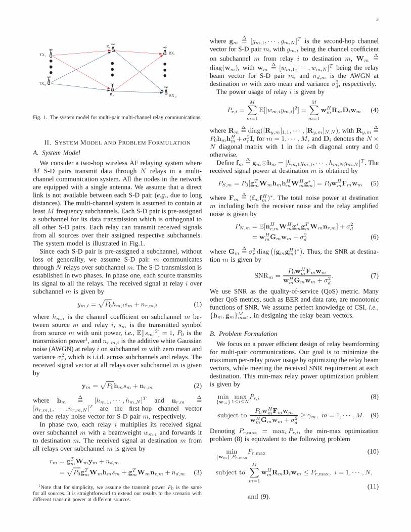
Fig. 1. The system model for multi-pair multi-channel relaycommunications.
II. SYSTEM MODEL AND PROBLEM FORMULATION
A. System Model
We consider a two-hop wireless AF relaying system whereM S-D pairs transmit data throughN relays in a multi-channel communication system. All the nodes in the networkare equipped with a single antenna. We assume that a directlink is not available between each S-D pair (e.g., due to longdistances). The multi-channel system is assumed to containatleastM frequency subchannels. Each S-D pair is pre-assigneda subchannel for its data transmission which is orthogonal toall other S-D pairs. Each relay can transmit received signalsfrom all sources over their assigned respective subchannels.The system model is illustrated in Fig.1.
Since each S-D pair is pre-assigned a subchannel, withoutloss of generality, we assume S-D pairm communicatesthroughN relays over subchannelm. The S-D transmission isestablished in two phases. In phase one, each source transmitsits signal to all the relays. The received signal at relayi oversubchannelm is given by
ym,i =√
P0hm,ism + nr,m,i (1)
wherehm,i is the channel coefficient on subchannelm be-tween sourcem and relayi, sm is the transmitted symbolfrom sourcem with unit power,i.e., E[|sm|2] = 1, P0 is thetransmission power1, andnr,m,i is the additive white Gaussiannoise (AWGN) at relayi on subchannelm with zero mean andvarianceσ2
r , which is i.i.d. across subchannels and relays. Thereceived signal vector at all relays over subchannelm is givenby
ym =√
P0hmsm + nr,m (2)
where hm∆= [hm,1, · · · , hm,N ]T and nr,m
∆=
[nr,m,1, · · · , nr,m,N ]T are the first-hop channel vectorand the relay noise vector for S-D pairm, respectively.
In phase two, each relayi multiplies its received signalover subchannelm with a beamweightwm,i and forwards itto destinationm. The received signal at destinationm fromall relays over subchannelm is given by
rm = gTmWmym + nd,m
=√
P0gTmWmhmsm + gT
mWmnr,m + nd,m (3)
1Note that for simplicity, we assume the transmit powerP0 is the samefor all sources. It is straightforward to extend our resultsto the scenario withdifferent transmit power at different sources.
where gm∆= [gm,1, · · · , gm,N ]T is the second-hop channel
vector for S-D pairm, with gm,i being the channel coefficient
on subchannelm from relay i to destinationm, Wm∆=
diag(wm), with wm∆= [wm,1, · · · , wm,N ]T being the relay
beam vector for S-D pairm, and nd,m is the AWGN atdestinationm with zero mean and varianceσ2
d, respectively.The power usage of relayi is given by
Pr,i =
M∑
m=1
E[|wm,iym,i|2] =M∑
m=1
wHmRmDiwm (4)
whereRm∆= diag([Ry,m]1,1, · · · , [Ry,m]N,N), with Ry,m
∆=
P0hmhHm+σ2
rI, for m = 1, · · · ,M , andDi denotes theN ×N diagonal matrix with 1 in thei-th diagonal entry and 0otherwise.
Definefm∆= gm⊙hm = [hm,1gm,1, · · · , hm,Ngm,N ]T . The
received signal power at destinationm is obtained by
PS,m = P0[gTmWmhmhH
mWHmg∗
m] = P0wHmFmwm (5)
whereFm∆= (fmfHm )∗. The total noise power at destination
m including both the receiver noise and the relay amplifiednoise is given by
PN,m = E[nHr,mWH
mg∗mgT
mWmnr,m] + σ2d
= wHmGmwm + σ2
d (6)
whereGm∆= σ2
r diag(
(gmgHm)∗
)
. Thus, the SNR at destina-tion m is given by
SNRm =P0w
HmFmwm
wHmGmwm + σ2
d
. (7)
We use SNR as the quality-of-service (QoS) metric. Manyother QoS metrics, such as BER and data rate, are monotonicfunctions of SNR. We assume perfect knowledge of CSI,i.e.,{hm,gm}Mm=1, in designing the relay beam vectors.
B. Problem Formulation
We focus on a power efficient design of relay beamformingfor multi-pair communications. Our goal is to minimize themaximum per-relay power usage by optimizing the relay beamvectors, while meeting the received SNR requirement at eachdestination. This min-max relay power optimization problemis given by
min{wm}
max1≤i≤N
Pr,i (8)
subject toP0w
HmFmwm
wHmGmwm + σ2
d
≥ γm, m = 1, · · · ,M. (9)
Denoting Pr,max = maxi Pr,i, the min-max optimizationproblem (8) is equivalent to the following problem
min{wm},Pr,max
Pr,max (10)
subject toM∑
m=1
wHmRmDiwm ≤ Pr,max, i = 1, · · · , N,
(11)
and (9).

4
III. M INIMIZING MAXIMUM PER-RELAY POWER USAGE
The per-relay power minimization problem (10) is non-convex due to the SNR constraint (9). To solve it, we firstexamine the feasibility of the problem. Then we show that thesolution can be obtained in the dual domain. The dual problemis further converted into an SDP with polynomial worst-casecomplexity. We obtain a semi-closed form structure of thebeam vectors{wm} and propose our algorithm to obtain theoptimal dual variables in determining{wm}.
We first give the necessary condition for which the opti-mization problem (10) is feasible.
Proposition 1: A necessary condition for the feasibility ofthe relay power minimization problem (10) is
min1≤m≤M
P0
γmfHmG†
mfm > 1. (12)
Proof: See Appendix A.Note that the condition in (12) directly reflects the feasibility
of the SNR constraint in (9), as shown in Appendix A. Inother words, if the condition in (12) is not satisfied, the SNRconstraint (9) cannot be satisfied for allm no matter what{wm} is used.
A. The Dual Approach
Although the optimization problem (10) is non-convex, weshow that the strong duality holds and hence the problem (10)can be solved in the Lagrange dual domain. The result is givenbelow.
Proposition 2: The per-relay power minimization problem(10) has zero duality gap.
Proof: See Appendix B.By Proposition 2, since the zero duality gap holds for
the problem (10), the optimal beam vectors{wom}Mm=1 can
be obtained through the Lagrange dual domain. Letλ∆=
[λ1, · · · , λN ]T andα∆= [α1, · · · , αM ]T denote the Lagrange
multipliers associated with the per-relay power constraint (11)and SNR constraint (9), respectively. The dual problem of theproblem (10) is given by
maxλ,α
min{wm},Pr,max
L({wm}, Pr,max,λ,α) (13)
subject to λ � 0,α � 0. (14)
The LagrangianL({wm}, Pr,max,λ,α) in (13) is given by
L({wm}, Pr,max,λ,α) =
M∑
m=1
αmσ2d + Pr,max(1−
N∑
i=1
λi)
+
M∑
m=1
wHm
(
Km − αmP0
γmfmfHm
)
wm
(15)
where
Km∆= RmDλ + αmGm (16)
andDλ
∆= diag(λ1, · · · , λN ).
The dual problem (13) can be shown to be equivalent to thefollowing problem:
maxλ,α
M∑
m=1
αmσ2d (17)
subject to Km � αmP0
γmfmfHm , m = 1, · · · ,M, (18)
N∑
i=1
λi ≤ 1, (19)
and (14).
To see the equivalence, note that if either (18) or (19) isnot satisfied, there exists some{wm, Pr,max} resulting inL({wm}, Pr,max,λ,α) = −∞, which cannot be an optimalsolution of the dual problem (13). Therefore, the constraints(18) and (19) are met at the optimality of the problem (13).After the inner minimization with respect to (w.r.t.){wm} andPr,max, the objective of the dual problem (13) is equivalent tothat in (17).
To solve the problem (17) for the optimal dual variables{λo,αo}, we now show that it can be reformulated into anSDP given below to obtain the solution.
miny
aTy (20)
subject to bTy ≤ 1, y � 0M+N∑
j=1
yjΨm,j � 0, m = 1, · · · ,M
where y∆= [αT ,λT ]T , a
∆= [−σ2
d1TM×1,0
TN×1]
T , b∆=
[0TM×1,1
TN×1]
T , Ψm,m∆= P0
γmfmfHm − Gm, Ψm,M+i
∆=
−RmDi for m = 1, · · · ,M, i = 1, · · · , N , and all otherΨm,j are zeros.
The above SDP can be solved efficiently using a standardSDP solver [30]. Obtaining the optimal beam vector solution{wo
m}Mm=1 of the problem (13) depends on the values of theoptimal dual variables{λo,αo}. In the following, we partitionthe values of{λo,αo} into three cases and derive{wo
m}Mm=1
in each case. We first present the following lemma showing acertain condition on the value ofαo.
Lemma 1: If λo ≻ 0, thenαo ≻ 0.
Proof: See Appendix C.Note thatλo andαo are the optimal dual variables associatedwith the per-relay power constraint (11) and SNR constraint(9), respectively. The Karush-Kuhn-Tucker (KKT) conditionsrequire complementary slackness. Thus, Lemma 1 indicatesthat if the per-relay power constraint is active (i.e., attainedwith equality) at optimality, then the SNR constraint is alsoactive at optimality. However, note thatαo
m could be zero forsomem, if λo
i is zero for somei.
B. The Optimal Beam Vector {wom}
Using Lemma 1, in the following, we partition the valuesof {λo,αo} into three cases to derive{wo
m}Mm=1.

5
1) Case 1: λo = 0. In this case,Km in (16) reduces to
αmGm. For the constraint (18) to hold, we haveαo = 0 (alsosee Appendix C). As a result, the objective in (17) becomeszero. If the SNR constraint (9) could be satisfied for allm,i.e., the original problem (10) is feasible, the optimal objectivehas to be strictly greater than zero which is a contradiction.This implies the per-relay power minimization problem (10)isinfeasible. In other words, if the optimization problem (10) isfeasible, there should be at least onei such that (11) is activeat optimality,i.e., λo
i > 0.2) Case 2: λ
o ⊁ 0 andλo 6= 0. In this case, we haveλoi =
0 for somei’s andαom = 0 for somem’s. In the following, we
first consider the case in which at optimality, only one entryin λ
o and αo is strictly positive. In other words, only one
S-D pair and one relay meet the SNR constraint and powerconstraint with equality, respectively. Then, we explain howto extend our solution to the case in whichλo
i > 0, αom > 0
for arbitrary i’s andm’s. Denotem and i such thatαom > 0
andλi > 0, respectively, andαom = 0 for m 6= m andλo
i = 0for i 6= i. In this case, we haveλi = 1 from the maximizationproblem (17), since its optimal objective is increasing w.r.t.λi.
In the following, we first obtain the optimal beam vectorwo
m. For m 6= m, the optimal beam vectorwom cannot be
derived in a similar way as that forwom. Instead, we formulate
a new optimization problem to obtainwom.
Proposition 3: Assumeαom > 0. The optimal beam vector
wom for the per-relay power minimization problem (10) is
given by
wom = ζmKo
m†fm (21)
where
ζm∆= σd
[
P0
γm|fHmKo
m†fm|2 − fHmKo
m†GmKo
m†fm
]− 1
2
(22)
with Kom obtained by substituting the optimal dual variables
αom andλo into (16).
Proof: See Appendix D.Define M ∆
= {1, · · · ,M} \ {m}, and definePi,m∆=
wom
HRmDiwom as the power used at relayi for S-D pair
m. The beamforming vectors{wm,m ∈ M} are determinedthrough solving the following feasibility problem
find {wm,m ∈ M} (23)
subject to max1≤i≤N
Pi,m +∑
m∈M
wHmRmDiwm = P o
r,max,
P0wHmFmwm
wHmGmwm + σ2
d
≥ γm, m ∈ M. (24)
There is no unique solution for the feasibility problem (23).However, we can always scalewm such that (24) meetswith equality for m ∈ M. Since we assumeαo
m = 0 form 6= m, the optimal objective of the original problem (10) isP or,max = αo
mσ2d. By Proposition 2, this means, at optimality,
the Lagrangian in (15) isαomσ2
d. It follows that, under theassumedαo, λo, we have
∑
m∈M wHmRmDiwm = 0. Since
λi > 0, the power constraint (11) fori is met with equality,and we havePi,m = P o
r,max.
As analyzed above, at optimality, except S-D pairm, relay idoes not forward signal from any other sourcem ∈ M. Thus,to obtainwo
m for m ∈ M, we now propose the following relaypower minimization problem by excluding the considerationof S-D pairm and restricting the power usage on relayi
min{wm,m∈M},Pr
Pr (25)
subject to∑
m∈M
wHmRmDiwm ≤ 0,
∑
m∈M
wHmRmDiwm ≤ Pr, ∀i 6= i, (26)
and (24).
Following similar argument as Proposition 2, we can showthat zero duality gap holds for the problem (25). This problemcan be reformulated in the dual domain into an SDP, given by
miny
cTy (27)
subject to
M+N∑
j=1
yjΨm,j � 0, m ∈ M,
y � 0,dTy ≤ 1
wherey is defined the same way as in (20),c is defined thesame way asa in (20) except for them-th entry,cm, beingzero, andd is defined the same way asb in (20) except forthe (M + i)-th entry being zero.
The terms corresponding to S-D pairm are eliminated inboth the objective and constraints of (27), which is consistentwith the problem formulation (25).
For the optimization problem (25), we repeat our procedureto evaluate the values of{αo
m, m ∈ M}.2 If αom > 0 for all
m ∈ M, then we can find{wom, m ∈ M} similarly to Case 3
as discussed in the following. Otherwise, we follow the stepsto obtain the solution in Case 2. For example, suppose theper-relay power constraint (26) and SNR constraint (24) areactive for some relayi and some S-D pairm, i.e., λo
i> 0 and
αom > 0. Let P o
r denote the minimum value of (25). As theminimum objective of (10) isP o
r,max, we haveP or + Pi,m ≤
P or,max, and we can findwo
m with similar structure as in (21)by substituting the optimal dual variables obtained from (27)into (16).
So far, we have proposed our algorithm to obtain the optimalbeam vector solution{wo
m}, assuming only one entry inαo
and λo is strictly positive. The proposed procedure can be
extended to the general case where multiple entries inαo and
λo are positive. In this case, we defineIα ∆
= {m | αom > 0}
and Iλ ∆= {i | λo
i > 0}. According to Proposition 3, theoptimalwo
m for m ∈ Iα has a similar expression as in (21).Then, we can solve a feasibility problem similar to (23) tofind wo
m for m ∈ {1, · · · ,M} \ Iα. The feasibility problemcan be reformulated into an SDP similar to (27) with updatedc, d, andΨm,j according toIα andIλ.
2Note that the problem (25) is feasible. This is because we consider Case2 for the original problem, which means the problem is feasible. Thus, onlyCases 2 or 3 will happen in the subsequent iterative procedure.
6
Algorithm 1 Solving the per-relay power minimization prob-lem (10)
1: Check the feasibility condition (12).2: Solve the SDP problem (20) to obtain the optimal dual
variables{αo,λo}.3: ObtainIα = {m | αo
m > 0} andIλ = {i | λoi > 0}.
4: SetΠα = Iα.5: while Iα 6= {1, · · · ,M} do6: ComputeKo
m and findwom in (21) for all m ∈ Πα.
7: Updatec andd as defined below the problem (27).8: Solve the SDP problem (27).9: Find Πα = {l ∈ {1, · · · ,M} \ Iα|αo
l > 0}andΠλ = {q ∈ {1, · · · , N} \ Iλ|λo
q > 0}.10: UpdateIα = Iα ∪ Πα andIλ = Iλ ∪Πλ.11: end while12: ComputeKo
m and findwom in (21) for all m ∈ Πα.
3) Case 3: λo ≻ 0. According to Lemma 1, we haveαo ≻
0. FromKm in (16), this means that ifKom−αo
mGm ≻ 0, thenαom > 0 for all m, and the solution is given by Proposition 3.
According to the proof in Appendix D, it can be shown thatαo
mP0
γmfHmKo
m†fm = 1, for m = 1, · · · ,M . In this case, since
αo ≻ 0, we obtain the optimal beam vectorswo
m directly bythe semi-closed form solution given by (21).
Corollary 1: The maximum per-relay power for the originalproblem (10) is given by
P or,max =
M∑
m=1
αomσ2
d = σ2d
M∑
m=1
γm
P0fHmKom
†fm. (28)
Proof: The first equality in (28) is due to the zero dualitygap by Proposition 2. As shown in Appendix D for Case 3,we haveαo
mP0
γmfHmKo
m†fm = 1 at optimality. Substitutingαo
m
into the objective of (17), we arrive at the expression at theright-hand side of (28).Combining Cases 2 and 3, we summarize our algorithmfor solving per-relay power minimization problem (10) inAlgorithm 1.
Note that for both Cases 2 and 3, the beam vector solutionhas the semi-closed form structure given in (21). Hence, wecan provide the necessary and sufficient condition for thefeasibility of (10). Note that forζm in (22) to be real, theterm in the bracket at the right-hand side of (22) should bepositive. Therefore, the problem (10) is feasible if and only ifthere existsα � 0, λ � 0, with
∑Ni=1 λi ≤ 1 such that
min1≤m≤M
P0
γm|fHmK†
mfm|2 − fHmK†mGmK†
mfm > 0. (29)
C. Complexity Analysis
Now we analyze the complexity of Algorithm 1. Note thatthe optimization problem (10) has been converted to an SDPproblem in (20) withM + N variables andM linear matrixinequality constraints. The SDP can be solved efficientlyusing interior-point methods with standard SDP solvers suchas SeDuMi [31], [32]. In the following, we analyze thecomplexity based on the standard SDP form in [31]. Based
on the complexity analysis of the standard SDP form, for theSDP withM + N variables, andM linear matrix inequalityconstraints of the size given, the computation complexity periteration to solve (20) isO
(
(M +N)2MN2)
. The number ofiterations to solve SDP is typically between 5 to 50 regardlessof problem size [31]. Thus, the complexity to solve the SDPis O
(
(M +N)2MN2)
.Note that the overall computation complexity to solve
the optimization problem (10) depends on the values of theoptimal dual variables. As shown in Section III-B, if Case 3happens, only one SDP problem (20) is solved,i.e., the com-plexity is given byO
(
(M + N)2MN2)
. If Case 2 happens,at mostM SDP problems formulated as (27) are solved,i.e.,the worst-case complexity is given byO
(
(M +N)2M2N2)
.In both cases, the algorithm has a polynomial worst-casecomplexity w.r.t. the number of relays and S-D pairs. Notethat the above analysis is based on worst-case complexityestimates. In practice, the complexity is much lower than theworst-case estimate [31].
IV. M AXIMIZING M INIMUM SNR
The ultimate end-to-end performance measures of the net-work such as the data rate or bit-error-rate (BER) are directfunctions of the received SNR. It is often desirable to maxi-mize the worst received SNR at the destinations under powerconstraints. In this section, we formulate the max-min SNRproblem subject to per-relay power constraints, and show thatit is the inverse problem of the min-max per-relay powersubject to SNR constraints. Thus, we propose an iterativealgorithm through bisection search to solve the max-min SNRproblem.
In a typical system, the relays have the same front-endamplifiers and the destinations have the same minimum SNRrequirements. In the following, we assume identical per-relaypower budgets and minimum SNR requirements for the relaysand destinations, respectively. Extension to the non-uniformpower and/or SNR requirement scenarios can follow a similarapproach, and is omitted for simplicity.
The problem of maximizing the minimum received SNRunder a maximum per-relay power budget can be formulatedas
max{wm},γ
γ (30)
subject toM∑
m=1
wHmRmDiwm ≤ Pr,0, i = 1, · · · , N,
SNRm ≥ γ, m = 1, · · · ,M
wherePr,0 denotes the relay power budget. The min-max relaypower optimization problem (10) with a common SNR targetγ0 is given by
min{wm},Pr
Pr (31)
subject to SNRm ≥ γ0, m = 1, · · · ,M,M∑
m=1
wHmRmDiwm ≤ Pr, i = 1, · · · , N.

7
Algorithm 2 Solving the min SNR maximization problem (30)
1: Set γ0,min such thatP or (γ0,min) < Pr,0 andγ0,max such
thatP or (γ0,max) > Pr,0. Setε.
2: Setγ0 =γ0,min+γ0,max
2.
3: Solve the optimization problem (31) underγ0.4: if P o
r (γ0) > Pr,0 then5: Setγ0,max = γ0 andPr = 0 (or Pr < Pr,0 − ε).6: else7: Setγ0,min = γ0 andPr = P o
r (γ0).8: end if9: if Pr < Pr,0 − ε then
10: Repeat (3)–(9); otherwise, returnγ0.11: end if
−20 −10 0 10 20 300
0.1
0.2
0.3
0.4
0.5
0.6
0.7
0.8
0.9
1
Maximum normalized per-relay power (dB)
CDF
N = 2i for i = 0, ..., 5
Fig. 2. CDF of maximum normalized relay power withM = 2.
We use the notationsγo(Pr,0) and P or (γ0) to denote the
optimal objectives in problems (30) and (31), to emphasizetheir dependency onPr,0 andγ0, respectively. The followingproposition shows the property ofγo(Pr,0) as a function ofPr,0.
Proposition 4: The optimal max received SNRγo(Pr,0) isa continuous and strictly monotonically increasing function ofPr,0, and anyγ < γo(Pr,0) is achievable.
Proof: See Appendix E.
Following Proposition 4, the min-max per-relay powerPr,0 is achieved whenγo(Pr,0) = γ0, for any γ0, i.e.,P or
(
γo(Pr,0))
= Pr,0. Hence the optimization problem (30)is the inverse problem of (31),i.e.,
P or
(
γo(Pr,0))
= Pr,0, γo(
P or (γ0)
)
= γ0.
As a result, the SNR maximization problem (30) can besolved iteratively by solving the per-relay power minimizationproblem (31) with bisection search on the maximum per-relaypower targetPr such thatPr → Pr,0. The steps to solvethe max-min SNR problem (30) using bisection search aresummarized in Algorithm 2. It is shown in [31] that SDP prob-lems have nearly linear convergence regardless of the problemsize. Furthermore, it is well-known that the bisection algorithmused in Algorithm 2 converges inlog(γ0,max−γ0,min)− log εiterations.
5 6 7 8 9 10 11 12 13 14 150
0.1
0.2
0.3
0.4
0.5
0.6
0.7
0.8
0.9
1
Average normalized received signal power (dB)
CDF
N = 2i for i = 0, ..., 5
Fig. 3. CDF of average normalized received signal power withM = 2.
0 1 2 3 4 5 6 7 8 9 100
0.1
0.2
0.3
0.4
0.5
0.6
0.7
0.8
0.9
1
Average normalized received noise power (dB)
CDF
N = 2i for i = 0, ..., 5
Fig. 4. CDF of average normalized received noise power withM = 2.
V. NUMERICAL RESULTS
In this section, we provide numerical results to evaluate theperformance of the proposed min-max relay power algorithm.In simulation, the noise powers at the relay and destinationareset toσ2
r = σ2d = 1. The first and second hop channelshm
andgm are assumed i.i.d. zero-mean Gaussian with variance1. The normalized source transmit power (against destinationnoise power) is set toP0/σ
2d = 10 dB. A total of 1000 feasible
realizations are used. Unless otherwise specified, the defaultminimum SNR guarantees are set toγm = γ0 = 5 dB form = 1, · · · ,M .3
A. Effect of the Number of Relays
In order to study the effect of the number of relays,N ,on the maximum relay power, we plot the CDF ofPr,max/σ
2d
obtained in problem (10) under different channel realizations,as shown in Fig. 2. We setM = 2. The number of relaysare chosen asN = 2i for i ∈ {0, · · · , 5}. It can be noticedthat asN increases, the CDF is shifted to the left, and it alsobecomes more concentrated. In addition, the CDF curves donot converge asN becomes very large. In fact, those curves areuniformly shifted to the left. The uniform shift is because ofthe power gain achieved by relay beamforming. The tightening
3Note that because of the differences between [29] and ours asdiscussedin Section I-B, we do not perform any comparison of our solution with thatof [29] in simulation.

8
−25 −20 −15 −10 −5 0 5 10 15 20−10
−8
−6
−4
−2
0
2
4
6
8
10
Average normalized maximum relay power (dB)
ReceivedworstSNR
(dB)
N = 2
N = 4
N = 8
N = 16
N = 32
Fig. 5. Averageminm SNRm versus averagePr,max/σ2
dwith M = 4.
−15 −10 −5 0 5 10 15 200
0.1
0.2
0.3
0.4
0.5
0.6
0.7
0.8
0.9
1
Maximum normalized per-relay power (dB)
CDF
M = 2i for i = 1, 2, 3, 4
Fig. 6. CDF of maximum normalized relay power withN = 4.
of CDF curves reflects the “hardening” of the effective channeldue to beamforming, in the sense that the distribution of theeffective channel becomes tighter.
The CDFs of the average received signal in (5) and noisepower in (6), each normalized againstσ2
d, with N = 2i fori ∈ {0, · · · , 5} andM = 2 are shown in Fig. 3 and Fig. 4,respectively. In both figures, we observe that, asN increases,the CDF is shifted to the left. Furthermore, the amount of shiftdecreases, and the CDF shape becomes tighter. In Fig. 4, asN increases, the amplified noise is reduced to zero, and theoverall noise converges to the receiver noise, which is 0 dB.This happens because the beam vector norm‖wm‖ decreasesas N increases. For Fig. 3, asN increases, the normalizedreceived signal power converges to 5 dB which is the minimumSNR requirement.
To demonstrate the result of the max-min SNR problem(30), in Fig. 5, the average minimum received SNR,i.e.,minm SNRm versus averagePr,max/σ
2d is plotted withM =
4, andN = 2i for i ∈ {1, · · · , 5}. To generate each curve,we set the minimum SNR requirementγ0 from -10 dB to 10dB. For eachγ0 value, 1000 realizations are generated andthe averagePr,max/σ
2d and minm SNRm are computed for
each realization. We see from Fig. 5 that,minm SNRm isa monotonically increasing function ofPr,max/σ
2d. Also, for
fixed Pr,max/σ2d, the minimum received SNRminm SNRm
increases by more than 5 dB asN doubles.
−20 −15 −10 −5 0 5 10 15−10
−8
−6
−4
−2
0
2
4
6
8
10
Average normalized maximum relay power (dB)
ReceivedworstSNR
(dB)
M = 2
M = 4
M = 8
M = 16
M = 32
Fig. 7. Averageminm SNRm versus averagePr,max/σ2
dwith N = 4.
−10 0 10 20 30 400
0.1
0.2
0.3
0.4
0.5
0.6
0.7
0.8
0.9
1
Maximum normalized per-relay power (dB)
CDF
True CSI
6-bit subchannel feedback
4-bit subchannel feedback
N = 1
N = 2
N = 4
N = 8
Fig. 8. Empirical CDF ofPr,max/σ2
dfor true CSI and limited feedback
(Scenario 1) withM = 2.
B. Effect of the Number of S-D Pairs
For fixedN = 4, the CDF of maximum relay powerPr,max
from the problem (10), normalized againstσ2d, under various
channel realizations is shown in Fig. 6, withM = 2i for i ∈{1, · · · , 4}. As expected, asM increases, more relay poweris needed,i.e., the CDF is shifted to the right.
In Fig. 7, the average minimum received SNR(minm SNRm) versus averagePr,max/σ
2d is presented
with N = 4, andM = 2i for i ∈ {1, · · · , 5}. We see that,as expected, the averageminm SNRm increases with averagePr,max/σ
2d, while it decreases asM increases because the
number of SNR constraints increases. Consequently, therelays increase transmission power in order to satisfy theSNR requirementγ0 for all destinations.
C. Effect of Imperfect CSI
So far, true CSI is assumed. To observe the robustness of theproposed algorithm w.r.t. the limited number of CSI feedbackbits and channel estimation error, we consider the followingtwo scenarios when second-hop perfect CSI is not available.
In Scenario 1, there is no error in estimating the second-hop CSI. However, there is a limited number of feedback bitsin order to send data to the relays. We consider equiprobablequantization of channel coefficients [33]. LetB denote thenumber of available feedback bits. In the equiprobable quanti-zation, every real and imaginary part of the channel coefficient

9
−10 0 10 20 30 400
0.1
0.2
0.3
0.4
0.5
0.6
0.7
0.8
0.9
1
Maximum normalized per-relay power (dB)
CDF
True CSI
α = 0.1
α = 0.3
N = 1
N = 2
N = 4
N = 8
Fig. 9. Empirical CDF ofPr,max/σ2
dfor true CSI and Gaussian channel
estimation error (Scenario 2) withM = 2.
on a subchannel is quantized with equal probability accordingto the CSI distribution, which is complex Gaussian.
In Scenario 2, the second-hop channels are estimated withestimation error; however, no feedback limit is imposed.Specifically, let us defineh = h + αh, where h is thetrue subchannel,h is the estimated subchannel used in theoptimization problem. The estimation errorh is assumedGaussian,i.e., h ∼ CN (0, 1). The weightα is set to adjustthe variance of error w.r.t. the variance of true CSI.
In Fig. 8, the CDF ofPr,max/σ2d under true CSI is compared
with that under imperfect CSI Scenario 1 with2B bits (B bitsfor each real and imaginary parts), whereB = 2 and 3. Notethat the performance under limited feedback is close to thecase of true CSI. The degradation is similar for allN values.
Finally, Fig. 9 shows the CDF ofPr,max/σ2d of true CSI
as compared with that under imperfect CSI Scenario 2 withthe channel estimation error beingα = 0.1 and 0.3. Again,we observe that the performance gap from the true CSIcase is relatively small. Furthermore, we observe that, unlikeScenario 1, the performance is sensitive toN . In particular,the performance degradation increases asN increases.
VI. CONCLUSIONS
In this paper, we have investigated the problem of relaybeamforming design in a multi-user peer-to-peer relay networkin a multi-channel system. Assuming perfect CSI, the problemof minimizing the maximum per-relay power usage subjectto minimum received SNR guarantees is formulated. It isshown that the non-convex problem satisfies strong duality.We have expressed its dual problem as an SDP with poly-nomial worst-case complexity. Based on the values of theoptimal dual variables, we have studied the optimal relaybeamforming vectors of the original problem in three cases.These cases have reflected at optimality whether the minimumSNR requirement at each S-D pair is met with equality, andwhether the power consumption at a relay is the maximumamong relays. Furthermore, we have shown that maximizingthe minimum received SNR subject to a fixed maximum relaypower constraint is the inverse problem of min-max relaypower subject to a minimum SNR constraint. The max-minSNR problem is solved iteratively using a bisection search.
We have numerically evaluated the proposed algorithm, andanalyzed the effect of various system parameters on theperformance of the optimal solution. Furthermore, we haveinvestigated the effect of imperfect CSI over the second hop,and quantified the performance loss due to limited feedbackor channel estimation error.
APPENDIX APROOF OFPROPOSITION1
Proof: The upper-bound ofSNRm is given by (7) byignoring the receiver noiseσ2
d in the denominator,i.e.,
SNRm∆=
P0|fHmwm|2wH
mGmwm. (A.1)
Note that a feasiblewm is not in the null space ofGm, i.e.,wm /∈ null{Gm}. The upper-bound (A.1) is invariable w.r.t.the scale ofw. For a fixed SNR upper-bound, the per-relaypower constraint (11) can be satisfied by scaling{w}. Hence,a necessary feasibility condition of (10) is given by
maxwm /∈null{Gm}
P0|fHmwm|2wH
mGmwm> γm, m = 1, · · · ,M. (A.2)
Using the solution of the generalized eigenvalue problem, theleft-hand side of (A.2) is maximized by substitutingwm =G†
mfm into (A.1). Noting that the maximum value of (A.1) isP0f
HmG†
mf , (12) is obtained and the proof is complete.
APPENDIX BPROOF OFPROPOSITION2
Proof: In order to prove the strong duality property, (10)is rewritten as an SOCP problem in conic form. The SOCP inconic form is convex and therefore has zero duality gap [30].We need to show that the dual of (10) is equivalent to the dualof the SOCP.
The per-relay power constraint (11) is convex w.r.t.w∆=
[wT1 , · · · ,wT
M ]T . However, the minimum received SNR con-straint (9) is non-convex. Reformulating the SNR constraint(9) in a conic form, we have
√
P0|wHmfm| ≥ √
γm
∥
∥
∥
∥
[
G1/2m wm
σd
]∥
∥
∥
∥
, m = 1, · · · ,M.
(B.1)
Note thatwm can have any arbitrary phase,i.e., it is obtaineduniquely up to a phase shift. The phase could be adjusted suchthat wH
mfm becomes real-valued form = 1, · · · ,M . Hence,the optimization problem (10) can be recast as
min{wm},Pr,max
Pr,max (B.2)
subject to
√
P0
γmwH
mfm ≥∥
∥
∥
∥
[
G1/2m wm
σd
]∥
∥
∥
∥
, m = 1, · · · ,M,
(B.3)
and (11)
which is an SOCP. The problem (B.2) is non-convex since theconstraint (B.3) is not in conic form. It is known that strongduality holds for SOCP in the conic form, but it may not holdin general forms [30]. However, the primal-dual optimality

10
conditions for the problems with constraints in the form of(B.3) are provided in [34, Proposition 3]. Following a similarproof, it can be shown that (B.2) has zero duality gap. In thefollowing, we show that the Lagrangian of (10) is the sameas the Lagrangian of (B.2) using a similar proof as in [35,Proposition 1].
The Lagrangian of (10) is given by
L1 = Pr,max +
N∑
i=1
λi
(
M∑
m=1
wHmRmDiwm − Pr,max
)
(B.4)
+
M∑
m=1
αm
(
σ2d +wH
mGmwm − P0
γm|wH
mfm|2)
.
The Lagrangian of (B.2) is obtained by
L2 = Pr,max +N∑
i=1
λi
(
M∑
m=1
wHmRmDiwm − Pr,max
)
(B.5)
+
M∑
m=1
αm
(
∥
∥
∥
∥
[
G1/2m wm
σd
]∥
∥
∥
∥
−√
P0
γm|wH
mfm|)
.
Denotingϕm∆=
∥
∥
∥
∥
[
G1/2m wm
σd
]∥
∥
∥
∥
+√
P0
γm|wH
mfm| ≥ σd and con-
verting the last term of the Lagrangian (B.5), it is equivalentto
L2 = Pr,max +
N∑
i=1
λi
(
M∑
m=1
wHmRmDiwm − Pr,max
)
+
M∑
m=1
αm
ϕm
(
σ2d +wH
mGmwm − P0
γm|wH
mfm|2)
.
Sinceϕm ≥ σd, by changing the variablesαm = αm
ϕm, there
existsαm ≥ 0 for any αm ≥ 0 andm = 1, · · · ,M such that(B.4) and (B.5) become exactly the same. As a result, strongLagrange duality holds for the non-convex problem (10).
APPENDIX CPROOF OFLEMMA 1
Proof: Substituting (16) into (18), the constraint (18) isequivalent to
RmDλ + αm
(
Gm − P0
γmfmfHm
)
� 0. (C.1)
Using contradiction, we show thatGm − P0
γmfmfHm is an
indefinite matrix. Suppose thatGm � P0
γmfmfHm . SinceGm is
a positive-definite matrix, we haveP0fHmG−1
m fm ≤ γm. ( [35,Lemma 1]). This contradicts the necessary condition for thefeasibility of (10) as shown in Proposition 1. Ifλo ≻ 0, thereexistsαo
m > 0 such that constraint (18) is satisfied. Note thatthe objective of the dual problem increases asαm increases.If there existsλo
i = 0 for somei, thenαom can be zero for
somem.
APPENDIX DPROOF OFTHEOREM 3
Proof: Suppose thatλo satisfies the necessary conditionin Lemma 1, i.e., the optimal dual variables are in the setdefined by Lemma 1. The constraint (18) can be rewritten asan equivalent inequality using [35, Lemma 1] as follows. Thedual problem (17) is equivalent to
maxλ
maxα
M∑
m=1
αmσ2d (D.1)
subject toαmP0
γmfHmK−1
m fm ≤ 1, m = 1, · · · ,M, (D.2)
(19), and (14).
In the following, we show the duality between (D.1) and SIMObeamforming problem similarly to [35]. Comparing (D.1) withthe optimization problem
maxλ
minα
M∑
m=1
αmσ2d (D.3)
subject toαmP0
γmfHmK−1
m fm ≥ 1, m = 1, · · · ,M, (D.4)
(19), and (14),
we see that the inner maximization in (D.1) becomes mini-mization in (D.3) and the SNR inequality is reversed. Substi-tuting (16) into the left-hand side of (D.2), we define
Φm(αm)∆=
αmP0
γmfHmK−1
m fm, (D.5)
which is a monotonically increasing function ofαm > 0 forλo. Therefore, the constraints (D.2) and (D.4) are met with
equality at optimality. The two problems (D.1) and (D.3) havethe same optimal valueαo
m satisfyingΦm(αom) = 1 for m =
1, · · · ,M , i.e., the optimization problems (D.1) and (D.3) areequivalent. The SIMO beamforming problem (D.3) is givenby substitutingwm = αmP0∑
Mm=1
αmσ2
d
K†mfm into
maxλ
minwm,α
M∑
m=1
αmσ2d (D.6)
subject toαmP0|wH
mfm|2
‖K1
2
mwm‖2≥ γm, m = 1, · · · ,M, (D.7)
(19), and (14).
ForM destinations each equipped withN antennas, the innerminimization of (D.6) is the SIMO beamforming problem,where the transmit power and destinationm noise covariance
matrix are∑M
m=1αmσ2
d andKm∆=
∑Mm=1
αmσ2
d
αmP0
Km, respec-tively. The solution of the inner minimization of the SIMObeamforming problem (D.6), is obtained bywo
m = K†mfm.
Note that (D.3) is given by substitutingwom into (D.6). The
solution wom can be scaled by any non-zero coefficientξ
such that the scaledξwom is also an optimal solution. Hence,
the optimization problems (D.1) and (D.6) are equivalent.Considering the condition forαo in Section III-B2, we have

11
Φm(αom) = 1 sinceαo
m > 0. Hence, the solution of (D.6)can be used to obtain onlywo
m in (10). The optimalwom for
m 6= m cannot be obtained using the solution of (D.6) becausethe constraints (D.2) and (D.4) are not met with equality ifαom = 0. The optimalm-th beam vector in (10) is given by
wom = ζmKo
mfm since the strong duality holds for (10) asshown in Proposition 2 and the solutionwo
m is unique onlyup to a scale factor. Due to KKT conditions andαo
m > 0, theSNR constraint (9) is met with equality. The coefficient (22)isobtained by substitutingwo
m into P0wHmFmwm
wHmGmwm+σ2
d
= γm, whichcompletes the proof.
APPENDIX EPROOF OFPROPOSITION4
Proof: Using contradiction, it can be shown that theoptimalγo(Pr,0) is strictly monotonically increasing functionof Pr,0. Suppose that{wm}Mm=1 is the optimal beam vectorof the max-min problem (30) achievingγo(Pr,0). Let usassumePr,1 > Pr,0 and γo(Pr,1) ≤ γo(Pr,0) for somePr,1 and Pr,0. The beam vectors{wm}Mm=1 can be scaledby a real-valued0 < χ < 1 such that, under{χwm}Mm=1,the SNR becomesγo(Pr,1) with the resulting maximum per-relay power usageχ2Pr,0 < Pr,1. This contradicts with theassumption thatPr,1 is optimal for γ = γo(Pr,1). It is notdifficult to show thatγo(Pr,0) is continuous w.r.t.Pr,0. Inorder to show that anyγ < γo(Pr,0) is achievable, let us
denoteν∆= argminm=1,··· ,M SNRm and
η∆=
σd(
P0
γ wHν Fνwν −wH
ν Gνwν
)1
2
> 0. (E.1)
Note that the denominator ofη is positive sinceγ < γo(Pr,0).After some manipulation, it can be shown that{ηwm}Mm=1
achieves any arbitraryγ < γo(Pr,0).
REFERENCES
[1] 3GPP TS 36.211 V8.2.0, Rel-8 Evolved universal terrestrial radio access(E-UTRA); physical channels and modulation, Mar. 2008.
[2] 3GPP TR 36.814, Rel-9 Evolved universal terrestrial radio access (E-UTRA); further advancements for E-UTRA physical layer aspects, Mar.2010.
[3] S. Chen and J. Zhao, “The requirements, challenges, and technologiesfor 5G of terrestrial mobile telecommunication,”IEEE Commun. Mag.,vol. 52, pp. 36–43, May 2014.
[4] T. Q. S. Quek, H. Shin, and M. Z. Win, “Robust wireless relay networks:Slow power allocation with guaranteed QoS,”IEEE J. Select. TopicsSignal Process., vol. 1, pp. 700–713, Dec. 2007.
[5] V. Havary-Nassab, S. ShahbazPanahi, A. Grami, and Z.-Q.Luo, “Dis-tributed beamforming for relay networks based on second-order statisticsof the channel state information,”IEEE Trans. Signal Process., vol. 56,pp. 4306–4316, Sep. 2008.
[6] Y. Jing and H. Jafarkhani, “Network beamforming using relays withperfect channel information,”IEEE Trans. Inf. Theory., vol. 55, pp.2499–2517, June 2009.
[7] L. Zhang, W. Liu, and J. Li, “Low-complexity distributedbeamformingfor relay networks with real-valued implementation,”IEEE Trans. SignalProcess., vol. 61, pp. 5039–5048, Oct. 2013.
[8] Y. Rong, “Multihop nonregenerative MIMO relays: QoS considerations,”IEEE Trans. Signal Process., vol. 59, pp. 290–303, Jan. 2011.
[9] Y. Fu, L. Yang, W.-P. Zhu, and C. Liu, “Optimum linear design of two-hop MIMO relay networks with QoS requirements,”IEEE Trans. SignalProcess., vol. 59, pp. 2257–2269, May 2011.
[10] L. Sanguinetti and A. A. D’Amico, “Power allocation in two-hopamplify-and-forward MIMO relay systems with QoS requirements,”IEEE Trans. Signal Process., vol. 60, pp. 2494–2507, May 2012.
[11] M. Dong, B. Liang, and Q. Xiao, “Unicast multi-antenna relay beam-forming with per-antenna power control: Optimization and duality,”IEEE Trans. Signal Process., vol. 61, pp. 6076–6090, Dec. 2013.
[12] M. Chen and A. Yener, “Power allocation for F/TDMA multiuser two-way relay networks,”IEEE Trans. Wireless Commun., vol. 9, pp. 546–551, Feb. 2010.
[13] V. Havary-Nassab, S. ShahbazPanahi, and A. Grami, “Optimal dis-tributed beamforming for two-way relay networks,”IEEE Trans. SignalProcess., vol. 58, pp. 1238–1250, Mar. 2010.
[14] Y.-U. Jang, E.-R. Jeong, and Y. H. Lee, “A two-step approach to powerallocation for OFDM signals over two-way amplify-and-forward relay,”IEEE Trans. Signal Process., vol. 58, pp. 2426–2430, Apr. 2010.
[15] Y. Jing and S. ShahbazPanahi, “Max-min optimal joint power controland distributed beamforming for two-way relay networks under per-nodepower constraints,”IEEE Trans. Signal Process., vol. 60, pp. 6576–6589,Dec. 2012.
[16] B. K. Chalise and L. Vandendorpe, “MIMO relay design formultipoint-to-multipoint communications with imperfect channel state information,”IEEE Trans. Signal Process., vol. 57, pp. 2785–2796, July 2009.
[17] S. Fazeli-Dehkordy, S. ShahbazPanahi, and S. Gazor, “Multiple peer-to-peer communications using a network of relays,”IEEE Trans. SignalProcess., vol. 57, pp. 3053–3062, Aug. 2009.
[18] B. K. Chalise and L. Vandendorpe, “Optimization of MIMOrelaysfor multipoint-to-multipoint communications: Nonrobustand robust de-signs,”IEEE Trans. Signal Process., vol. 58, pp. 6355–6368, Dec. 2010.
[19] P. Ubaidulla and A. Chockalingam, “Relay precoder optimization inMIMO-relay networks with imperfect CSI,”IEEE Trans. Signal Pro-cess., vol. 59, pp. 5473–5484, Nov. 2011.
[20] N. Bornhorst, M. Pesavento, and A. B. Gershman, “Distributed beam-forming for multi-group multicasting relay networks,”IEEE Trans.Signal Process., vol. 60, pp. 221–232, Jan. 2012.
[21] M. Fadel, A. El-Keyi, and A. Sultan, “QoS-constrained multiuser peer-to-peer amplify-and-forward relay beamforming,”IEEE Trans. SignalProcess., vol. 60, pp. 1397–1408, Mar. 2012.
[22] Y. Cheng and M. Pesavento, “Joint optimization of source powerallocation and distributed relay beamforming in multiuserpeer-to-peerrelay networks,”IEEE Trans. Signal Process., vol. 60, pp. 2962–2973,June 2012.
[23] M. R. A. Khandaker and Y. Rong, “Interference MIMO relaychannel:Joint power control and transceiver-relay beamforming,”IEEE Trans.Signal Process., vol. 60, pp. 6509–6518, Dec. 2012.
[24] Y. Liu and A. P. Petropulu, “Cooperative beamforming inmulti-sourcemulti-destination relay systems with SINR constraints,” in Proc. IEEEICASSP, Mar. 2010, pp. 2870–2873.
[25] J. Chen and M. Dong, “Multi-antenna relay network beamforming de-sign for multiuser peer-to-peer communications,” inProc. IEEE ICASSP,May 2014, pp. 7594–7598.
[26] C.-B. Chae, T. Tang, R. W. Heath, and S. Cho, “MIMO relaying withlinear processing for multiuser transmission in fixed relaynetworks,”IEEE Trans. Signal Process., vol. 56, pp. 727–738, Feb. 2008.
[27] R. Zhang, C. C. Chai, and Y.-C. Liang, “Joint beamforming and powercontrol for multiantenna relay broadcast channel with QoS constraints,”IEEE Trans. Signal Process., vol. 57, pp. 726–737, Feb. 2009.
[28] Q. Cao, H. V. Zhao, and Y. Jing, “Power allocation and pricing inmultiuser relay networks using Stackelberg and bargaininggames,”IEEETrans. Veh. Tech., vol. 61, pp. 3177–3190, Sep. 2012.
[29] D. H. N. Nguyen and H. H. Nguyen, “Power allocation in wirelessmultiuser multi-relay networks with distributed beamforming,” IETCommun., vol. 5, pp. 2040–2051, Sep. 2011.
[30] S. Boyd and L. Vandenberghe,Convex Optimization. Cambridge, U.K.:Cambridge Univ. Press, Mar. 2004.
[31] L. Vandenberghe and S. Boyd, “Semidefinite programming,” SIAM Rev.,vol. 38, pp. 49–95, Mar. 1996.
[32] SeDuMi, Optmization software. [Online]. Available: http://sedumi.ie.lehigh.edu/.
[33] A. Gersho and R. M. Gray,Vector Quantization and Signal Compression.Norwell, USA: Kluwer Academic Publishers, Nov. 1991.
[34] A. Wiesel, Y. C. Eldar, and S. Shamai, “Linear precodingvia conicoptimization for fixed MIMO receivers,”IEEE Trans. Signal Process.,vol. 54, pp. 161–176, Jan. 2006.
[35] W. Yu and T. Lan, “Transmitter optimization for the multi-antennadownlink with per-antenna power constraints,”IEEE Trans. SignalProcess., vol. 55, pp. 2646–2660, June 2007.

12
Ali Ramezani-Kebrya received the B.Sc. degreefrom the University of Tehran, Tehran, Iran, and theM.A.Sc degree from Queen’s University, Kingston,Canada, in 2010 and 2012, respectively, both inelectrical engineering. In September 2012, he joinedthe Wireless Computing Lab (WCL) of the Depart-ment of Electrical and Computer Engineering, theUniversity of Toronto, Toronto, Canada, where heis currently working towards the Ph.D. degree. Hisresearch interests include device-to-device commu-nication, statistical signal processing, and optimiza-
tion.Mr. Ramezani-Kebrya received the IEEE Kingston Section M.Sc. Research
Excellence Award and the Ontario Graduate Scholarship (OGS).
Min Dong (S’00-M’05-SM’09) received the B.Eng.degree from Tsinghua University, Beijing, China, in1998, and the Ph.D. degree in electrical and com-puter engineering with minor in applied mathematicsfrom Cornell University, Ithaca, NY, in 2004. From2004 to 2008, she was with Corporate Researchand Development, Qualcomm Inc., San Diego, CA.In 2008, she joined the Department of Electrical,Computer and Software Engineering at Universityof Ontario Institute of Technology, Ontario, Canada,where she is currently an Associate Professor. She
also holds a status-only Associate Professor appointment with the Depart-ment of Electrical and Computer Engineering, University ofToronto since2009. Her research interests are in the areas of statisticalsignal processingfor communication networks, cooperative communications and networkingtechniques, and stochastic network optimization in dynamic networks andsystems.
Dr. Dong received the Early Researcher Award from Ontario Ministry ofResearch and Innovation in 2012, the Best Paper Award at IEEEICCC in2012, and the 2004 IEEE Signal Processing Society Best PaperAward. Sheserved as an Associate Editor for the IEEE TRANSACTIONS ON SIGNALPROCESSING (2010-2014), and as an Associate Editor for the IEEE SIGNALPROCESSING LETTERS (2009-2013). She was a symposium lead co-chairof the Communications and Networks to Enable the Smart Grid Sympo-sium at the IEEE International Conference on Smart Grid Communications(SmartGridComm) in 2014. She has been an elected member of IEEE SignalProcessing Society Signal Processing for Communications and Networking(SP-COM) Technical Committee since 2013.
Ben Liang (S’94-M’01-SM’06) received honors-simultaneous B.Sc. (valedictorian) and M.Sc. de-grees in Electrical Engineering from PolytechnicUniversity in Brooklyn, New York, in 1997 andthe Ph.D. degree in Electrical Engineering with aminor in Computer Science from Cornell Universityin Ithaca, New York, in 2001. In the 2001 - 2002academic year, he was a visiting lecturer and post-doctoral research associate with Cornell University.He joined the Department of Electrical and Com-puter Engineering at the University of Toronto in
2002, where he is now a Professor. His current research interests are in mobilecommunications and networked systems.
He has served as an editor for the IEEE Transactions on Communications,an editor for the IEEE Transactions on Wireless Communications, and anassociate editor for the Wiley Security and Communication Networks journal,in addition to regularly serving on the organizational and technical committeesof a number of conferences. He is a senior member of IEEE and a memberof ACM and Tau Beta Pi.
Gary Boudreau (M’84-SM’11) received a B.A.Sc.in Electrical Engineering from the University of Ot-tawa in 1983, an M.A.Sc. in Electrical Engineeringfrom Queens University in 1984 and a Ph.D. inelectrical engineering from Carleton University in1989.
From 1984 to 1989 he was employed as a commu-nications systems engineer with Canadian Astronau-tics Limited and from 1990 to 1993 he worked as asatellite systems engineer for MPR Teltech Ltd. Forthe period spanning 1993 to 2009 he was employed
by Nortel Networks in a variety of wireless systems and managementroles within the CDMA and LTE basestation product groups. In2010 hejoined Ericsson Canada where he is currently employed in theLTE systemsarchitecture group. His interests include digital and wireless communicationsas well as digital signal processing.
Ronald Casselmanreceived a BEng. in ComputerSystems Engineering from the Carleton Universityin 1986, and an MEng. in Computer Systems Engi-neering from Carleton University in 1993.
From 1987 to 1994 he was employed as a re-search engineer with the Computer Systems Engi-neering Department at Carleton University workingwith software development tools and software vi-sualization techniques. From 1995 to 2009 he wasemployed by Nortel as a software developer andproject/people leader. In 2010 he joined Ericsson
Canada working as a manager of an LTE Systems architecture team. He enjoysleading research teams and enabling Industry/University partnerships.


![MULTI FUNCTION GROUND FAULT RELAY [GFR]-5C, 10C](https://img.pdfslide.us/doc/110x75/616a522a11a7b741a3513879/multi-function-ground-fault-relay-gfr-5c-10c.jpg)