Embed Size (px)
Citation preview
PERCEPTION BASED QUALITY MEASURE FOR
IMAGE COMPRESSION AND TRANSMISSION
Thesis submitted in ful�llment of the requirement
for the degree of Doctor of Philosophy
School of Computer Science and Software Engineering
Monash University
Australia
December 1998
By
Le Phu Dung
Bachelor of Mathematics (Honors), Bachelor of Computer Science, Master
of Computing, Member of NY Academy of Sciences

DECLARATION
This thesis contains no material which has been accepted for the award of
any other degree in any other university. To the best of my knowledge, this
thesis contains no material previously published or written by another per-
son, except when due reference is made in the text of the thesis.
Le Phu Dung
i

ACKNOWLEDGEMENTS
I am grateful to my supervisor, Prof. Bala Srinivasan, for his able
guidance and support in all respects throughout my degree.
I extend my sincere thanks to Maria Indrawan, Campbell Wilson and
Mohammed Salahadin for their understanding, friendship, and patience for
the long period of time we shared the same o�ce. I also direct my thanks
to Ms Hannah Burton, the former administrative o�cer of the Department
of Computer Technology, and Mr Duke Fonias the chief technical o�cer, for
their friendly support. I would also like to thank Shonali Krishnaswamy ,
Rosanne J :Price and Santosh Kulkarni for their proof-reading of my thesis.
I dedicate this thesis to my parents and my dearest friends Kim and Lisa
for their love and support throughout my studies.
ii
Abstract
In recent years, the growing number of users using Wide World Web for
distributed multimedia information and the increasing number of applica-
tions that use digital images such as distributed image databases, digital
libraries, teleshopping, digital video and document imaging, have resulted
in at least three main problems. First, tra�c on the Internet has increased
tremendously so that users have been experiencing long delays for applica-
tions such as telebrowsing and teleshopping which are expected to provide
services quickly. The second problem is the high space requirements for stor-
ing digital images in many systems such as multimedia and image databases
and digital libraries. The third problem is the demand for an accurate and
consistent image quality measure.
The importance of image quality evaluation can be seen by the need for a
consistent and perceptually valid method to evaluate the e�ciency and com-
pare various lossy image compression techniques. In addition, a good image
quality measure can provide:
iii
1. quantisation improvement,
2. better selection of image representations,
3. support in constructing systems which allow images to be e�ciently
transmitted over the Internet.
The image quality evaluation plays an important role in developing solutions
to all the three problems mentioned above. This has motivated the research
covered in this thesis.
We �rst propose a new class of image quality measures by which image
quality is evaluated locally and globally in units that are larger than individ-
ual pixels. The results from the proposed idea shows that possible derived
measures are more accurate and consistent than the commonly used meth-
ods, viz., the mean-square-error (MSE) and its variants, and the colour-based
techniques.
Second, we test our hypothesis that higher image compression is possible
if a distortion measure that coincides with human visual perception better
than the MSE is used in designing image coding systems. To prove the
hypothesis, we �rst mathematically show that if a distortion measure D1 co-
incides with human visual perception better than D2, a coder which uses D1
in its quantisation process or best basis selection algorithm will produce bet-
ter image compression than the coder which uses D2. We design algorithms
iv
for constructing two new coders to test the hypothesis experimentally. In
the �rst coder, our proposed image quality measure is used to improve the
quantisation process of the coding. In the second coder, the proposed image
quality measure is used in the selection of the best wavelet packet bases. The
correctness of the hypothesis is mathematically shown and the experimental
results from our coders con�rm its superiority to other known coders.
Third, we propose the novel concept of multi-level browsing which al-
lows the overall volume of image data to be minimised before transmission.
This can provide an optimal solution to the image transmission problem.
We propose models for storing images, classi�cation of image quality, and a
framework for constructing a system that allows image compression meth-
ods and quality levels to be selected dynamically. The proposed multi-level
browsing is completely compatible with continuing advancements of network
technology, image transmission and image compression techniques.
v
Contents
1 Introduction 1
1.1 Space and Transmission Requirements of Digital Images . . . 7
1.1.1 Image Compression . . . . . . . . . . . . . . . . . . . . 8
1.1.2 Image Transmission . . . . . . . . . . . . . . . . . . . . 10
1.2 Image Quality Evaluation and Its Importance . . . . . . . . . 11
1.3 Motivation of the Research . . . . . . . . . . . . . . . . . . . . 13
1.4 Contributions of the Thesis . . . . . . . . . . . . . . . . . . . 16
1.5 Thesis Outline . . . . . . . . . . . . . . . . . . . . . . . . . . . 18
2 Mathematical Background 22
2.1 Introduction . . . . . . . . . . . . . . . . . . . . . . . . . . . . 22
2.2 Set and Measure Theory . . . . . . . . . . . . . . . . . . . . . 24
2.3 Metric and Hausdro� Spaces . . . . . . . . . . . . . . . . . . . 27
2.4 Mathematical Representations of Images . . . . . . . . . . . . 29
vi
2.5 Fractal Theory . . . . . . . . . . . . . . . . . . . . . . . . . . 31
2.6 Wavelets Transform . . . . . . . . . . . . . . . . . . . . . . . . 34
2.7 Multiresolution . . . . . . . . . . . . . . . . . . . . . . . . . . 40
2.8 Digital Filters . . . . . . . . . . . . . . . . . . . . . . . . . . . 41
2.9 Wavelets, Filters and Multiresolution . . . . . . . . . . . . . . 44
2.10 Summary . . . . . . . . . . . . . . . . . . . . . . . . . . . . . 45
3 Image Compression and Quality Evaluation 46
3.1 Image Compression . . . . . . . . . . . . . . . . . . . . . . . . 47
3.2 Image Compression With Vector Quantisation . . . . . . . . . 49
3.2.1 Scalar Quantisation . . . . . . . . . . . . . . . . . . . . 50
3.2.2 Vector Quantisation . . . . . . . . . . . . . . . . . . . 51
3.2.3 Space-Frequency Quantisation . . . . . . . . . . . . . . 61
3.3 Transform Image Coding . . . . . . . . . . . . . . . . . . . . . 63
3.4 Image Compression with Wavelets . . . . . . . . . . . . . . . . 66
3.5 Fractal Image Compression . . . . . . . . . . . . . . . . . . . . 70
3.5.1 Fractal Image Compression versus Other Compressions 74
3.5.2 Fractal-Wavelet Based Image Coding . . . . . . . . . . 76
3.6 Image Quality Evaluation . . . . . . . . . . . . . . . . . . . . 77
3.6.1 Subjective Image Quality Evaluation . . . . . . . . . . 79
3.6.2 Objective Image Quality Evaluation . . . . . . . . . . . 80
vii
3.7 Conclusion . . . . . . . . . . . . . . . . . . . . . . . . . . . . . 85
4 A New Class of Objective Image Quality Measures 88
4.1 Introduction . . . . . . . . . . . . . . . . . . . . . . . . . . . . 88
4.2 New Class of Objective Image Quality Measures . . . . . . . . 93
4.2.1 Derivable Image Quality Measures . . . . . . . . . . . 99
4.2.2 A Possible Realisation of IQME . . . . . . . . . . . . . 101
4.3 Applicability of IQME . . . . . . . . . . . . . . . . . . . . . . 107
4.4 Conclusion . . . . . . . . . . . . . . . . . . . . . . . . . . . . . 129
5 Compression Enhancement with Image Quality Measure 132
5.1 Introduction . . . . . . . . . . . . . . . . . . . . . . . . . . . . 132
5.2 Image Compression and the Inverse Problem . . . . . . . . . . 136
5.3 The Hypothesis and Its Analysis . . . . . . . . . . . . . . . . . 140
5.4 Quantisation Improvement with IQME . . . . . . . . . . . . . 142
5.4.1 Fractal-Wavelet Based Image Coding . . . . . . . . . . 143
5.4.2 IQIC1 Coding Algorithm . . . . . . . . . . . . . . . . . 146
5.4.3 Experimental Results . . . . . . . . . . . . . . . . . . . 150
5.5 Best Basis Selection Improvement with IQME . . . . . . . . . 155
5.5.1 Lattice Vector Quantisation . . . . . . . . . . . . . . . 156
5.5.2 Wavelet Packets . . . . . . . . . . . . . . . . . . . . . . 163
5.5.3 IQIC2 Coding Algorithm . . . . . . . . . . . . . . . . . 168
viii
5.5.4 Experimental Results . . . . . . . . . . . . . . . . . . . 177
5.6 Conclusion . . . . . . . . . . . . . . . . . . . . . . . . . . . . . 182
6 Multi-Level Browsing for E�cient Image Transmission 184
6.1 Introduction . . . . . . . . . . . . . . . . . . . . . . . . . . . . 184
6.2 Data Reduction with Image Compression . . . . . . . . . . . . 188
6.3 Progressive Image Transmission . . . . . . . . . . . . . . . . . 190
6.4 Image Communication Problem . . . . . . . . . . . . . . . . . 192
6.5 A Framework for Multi-level Browsing . . . . . . . . . . . . . 196
6.5.1 Image Quality Classi�cation . . . . . . . . . . . . . . . 201
6.5.2 Models for Storing Digital Images . . . . . . . . . . . . 204
6.6 Multi-level Browsing . . . . . . . . . . . . . . . . . . . . . . . 205
6.6.1 Performance of Multi-level Browsers . . . . . . . . . . 207
6.6.2 Image Quality and Multi-level Browsing . . . . . . . . 212
6.7 Conclusion . . . . . . . . . . . . . . . . . . . . . . . . . . . . . 214
7 Conclusion 216
7.1 A Class of Objective Quality Measures . . . . . . . . . . . . . 217
7.2 Perception Based Image Compression . . . . . . . . . . . . . . 219
7.3 Multi-level Browsing for E�cient Image Transmission . . . . . 222
References 223
ix
List of Figures
2.1 An M-channel �lter bank . . . . . . . . . . . . . . . . . . . . . . 43
2.2 A 2-channel perfect reconstruction �lter bank. (a) Analysis system
carries out the signal expansion. (b) Synthesis system recovers the
original signal. . . . . . . . . . . . . . . . . . . . . . . . . . . . 43
3.1 Partition of a space of dimension n = 2. Each vector x that belongs
to a region Si is quantised by yi = Q(x) . . . . . . . . . . . . . 53
3.2 A generic block structure of transform coding . . . . . . . . . . . 64
4.1 Lena's image with the insertion of noise, 1600 pixels are randomly
subtracted by 30 (PSNR = 40.73) . . . . . . . . . . . . . . . . . 95
4.2 Lena's image with the insertion of noise, 1600 pixels in the hat
area are subtracted by 30 (PSNR = 40.95) . . . . . . . . . . . . . 95
x
4.3 L1: Lena's reconstructed image compressed by Davis' coder 8:1
(RMSE = 2.727389, PSNR = 39.415861, CDIF = 0.000020, IQME
= 0.317126) . . . . . . . . . . . . . . . . . . . . . . . . . . . . 118
4.4 L2: Lena's reconstructed image compressed by an unreliable pro-
gram Unr1Comp 4:1 (RMSE = 65.279321, PSNR = 11.835291,
CDIF = 0.000020, IQME = 1.337111) . . . . . . . . . . . . . . . 118
4.5 M1: Mandrill's reconstructed image compressed by Davis' coder
64:1 (RMSE = 21.245285, PSNR = 21.585552, CDIF = 0.000572,
IQME = 0.688900) . . . . . . . . . . . . . . . . . . . . . . . . . 119
4.6 M2: Mandrill's reconstructed image compressed by an unreliable
program Unr2Comp 4:1 (RMSE = 52.643649, PSNR = 13.703884,
CDIF = 0.000544, IQME = 1.294374) . . . . . . . . . . . . . . . 119
4.7 L3: Lena's reconstructed image compressed by Davis' coder 64:1
(RMSE = 7.855745, PSNR = 30.227056, CDIF = 0.000044, IQME
= 0.569338) . . . . . . . . . . . . . . . . . . . . . . . . . . . . 120
4.8 L4: Lena's modi�ed image with the insertion of noise. One-third
of pixels are shifted down by 20 and the rest are shifted up by
15 (RMSE = 25.013991, PSNR = 20.167144, CDIF = 0.000228,
IQME = 0.241502) . . . . . . . . . . . . . . . . . . . . . . . . . 120
xi
4.9 M3: Mandrill's reconstructed image compressed by Davis' coder
4:1 (RMSE = 6.072964, PSNR = 32.462790, CDIF = 0.000554,
IQME = 0.186585) . . . . . . . . . . . . . . . . . . . . . . . . . 121
4.10 M4: Mandrill's modi�ed image with the insertion of noise. All the
pixel values in one area across the image are replaced by a single
value (RMSE = 5.617281, PSNR = 33.140280, CDIF = 0.000002,
IQME = 1.112431) . . . . . . . . . . . . . . . . . . . . . . . . . 121
4.11 Lena's original image . . . . . . . . . . . . . . . . . . . . . . . . 122
4.12 Lena's reconstructed image compressed by Davis' coder 4:1, RMSE
= 1.664277, PSNR = 43.706292, IQME = 0.169797 . . . . . . . . 122
4.13 Mandrill's original image . . . . . . . . . . . . . . . . . . . . . . 123
4.14 Mandrill's reconstructed image compressed by Davis' coder 4:1,
RMSE = 6.072964, PSNR = 32.462790, IQME = 0.186585 . . . . 123
4.15 The variation of IQME from image to image with JPEG . . . . . 126
4.16 The variation of RMSE from image to image with JPEG . . . . . 126
4.17 The variation of IQME from image to image with EPIC . . . . . . 127
4.18 The variation of RMSE from image to image with EPIC . . . . . 127
4.19 The variation of IQME from image to image with Davis' algorithm 128
4.20 The variation of RMSE from image to image with Davis' algorithm 128
xii
5.1 Lena's reconstructed image compressed by IQIC1MSE 64:1 (MSE
is used in the quantisation) . . . . . . . . . . . . . . . . . . . . . 153
5.2 Lena's reconstructed image compressed by IQIC1IQME 64:1 (IQME
is used in the quantisation) . . . . . . . . . . . . . . . . . . . . . 153
5.3 Mandrill's reconstructed image compressed by IQIC1MSE 64:1 (MSE
is used in the quantisation) . . . . . . . . . . . . . . . . . . . . . 154
5.4 Mandrill's reconstructed image compressed by IQIC1IQME 64:1
(IQME is used in the quantisation) . . . . . . . . . . . . . . . . 154
5.5 Representation of the isonorms for vectors with a L2 norm . . . . 160
5.6 Example of wavelet packet analysis tree (a) A full wavelet packet
tree. (b) A pruned wavelet packet tree . . . . . . . . . . . . . . . 165
5.7 Typical members of wavelet packet family expressed in tree-structured
forms and in the tiling of the time-frequency plane. (a) Wavelet
decomposition. (b) An example of arbitrary wavelet packet de-
composition. (c) Full STFT-like decomposition . . . . . . . . . . 166
5.8 Rate-distortion plane . . . . . . . . . . . . . . . . . . . . . . . . 169
5.9 Pruning criterion for each wavelet packet tree node: prune if (Dc1 +Dc2 )+
�(Rc1 +Rc2) > Dp + �Rp . . . . . . . . . . . . . . . . . . . . . 170
5.10 Lena's reconstructed image compressed by IQIC2MSE 64:1 (MSE
is used in the best wavelet packet basis selection algorithm) . . . . 180
xiii
5.11 Lena's reconstructed image compressed by IQIC2IQME 64:1 (IQME
is used in the best wavelet packet basis selection algorithm) . . . . 180
5.12 Mandrill's reconstructed image compressed by IQIC2MSE 64:1 (MSE
is used in the best wavelet packet basis selection algorithm) . . . . 181
5.13 Mandrill's reconstructed image compressed by IQIC2IQME 64:1
(IQME is used in the best wavelet packet basis selection algorithm) 181
6.1 Block structure of the proposed multi-level browser . . . . . . . . 207
xiv
List of Tables
4.1 Selected experimental results of MSE, colour-based and IQME
methods for the normal case using JPEG. The compression ratios
are rounded to the integers 4,8,16,32,64 for easy reading. However,
this does not a�ect the results when the three methods are com-
pared in terms of quality evaluation, since the same reconstructed
image �les are used. Also, note that JPEG does not degrade nicely,
especially when the compression ratio is higher than 32:1 . . . . . 112
4.2 Selected experimental results MSE, colour-based and IQME meth-
ods for the normal case using EPIC . . . . . . . . . . . . . . . . 113
4.3 Selected experimental results of MSE, colour-based and IQME
methods for the normal case using Davis' coder [Dav96] . . . . . . 114
xv
4.4 Selected experimental results showing poor performances of MSE
and colour-based methods, while IQME has good performance,
when di�erent possible types of noise are generated by buggy com-
pression programs . . . . . . . . . . . . . . . . . . . . . . . . . 115
4.5 Selected experimental results showing poor performances of MSE
and colour-based methods, while IQME has good performance,
when di�erent possible types of noise are generated . . . . . . . . 115
5.1 Selected experimental results (Compression-Ratio/PSNR) on pop-
ular images of Lena, Goldhill, Barbara and Mandrill from Davis'
compression algorithm and our coder IQIC1 where MSE and IQME
are respectively used in the quantisation process . . . . . . . . . . 152
5.2 Selected experimental results (Compression-Ratio/PSNR) on pop-
ular images of Lena, Goldhill, Barbara and Mandrill from JPEG,
EPIC [SA97], and and our IQIC2 where MSE and IQME are re-
spectively used in the best wavelet packet basis selection algorithm 178
5.3 Comparison of IQIC2 coder and E-JPEG, DCT-EZQ, EZW, and
Improved EZW (DCT and wavelet based) coders . . . . . . . . . 178
6.1 Encoding - decoding time (in seconds)/PSNR values of JPEG,
EPIC and Davis' compression techniques . . . . . . . . . . . . . 195
6.2 Typical example results in the case of model 1 . . . . . . . . . . . 211
xvi

6.3 Typical example results in the case of model 2 . . . . . . . . . . . 211
6.4 Typical example results in the case of model 3 . . . . . . . . . . . 212
xvii
Chapter 1
Introduction
Today's information is in the form of multimedia, which not only consists
of text, numeric data and audio, but also images and video. The important
role of digital images is seen by the growing number of applications that use
digital images such as scienti�c visualisation, image documenting, digital li-
braries, multimedia and image databases. Digital images are important data
which in many circumstances can provide vital information (e.g., medical
imaging, geography image sensing), however, there is a major problem with
using digital images. That is that a large data volume generated when an
image is digitised, and hence a digital image requires more space to store and
takes more time to process and transmit.
1
The pressure for reducing storage and transmission time for still and
moving images has motivated research into image compression and many
successful image compression methods have been proposed. Early image
compression techniques focus on quantisation and this has lead to a number
of image compression algorithms based mainly on the enhancement of quanti-
sation techniques such as vector quantisation [HW85, HG88, NK88, CLG89],
lattice quantisation [JG89].
Image compression using quantisation still continues to evolve and new
quantisation techniques have been proposed to provide more e�cient com-
pression such as image compression using zerotree [Sha93], image compression
with space-frequency quantisation [XRO93, XRO94]. There are other com-
pression techniques based on new ways of representing natural images such
as image coding based on the Discrete Cosine Transform (DCT) [Wal91],
subband image coding [WO86, CR94], image compression through wavelet
transform coding [DJL92, ABMD92, CAS+92], and image compression based
on fractal theory [BJ88, Jac90]. Most attempts in image compression focus on
�nding new ways to better represent images so that higher compression can
be obtained. For example, in one direction, image coding based on wavelet
[ABMD92, LK92, Sha93] and wavelet packets [CMQW92, RV93, XRO94]
promise higher compression since for the same level of quality fewer coe�-
2
cients are required to represent the signal than using Discrete Cosine Trans-
form [DJL92, Sha93]. In the other direction, fractal image compression has
also shown its advantages over traditional image compression techniques such
as compression based on DCT or on vector quantisation. Especially, for im-
ages which possess a high level of self-similarity, high compression can be
obtained with fractal-based compression [BS88, Fis95].
While the study of new theories for representing images can lead to better
image compression, research in image compression has also tried to under-
stand the human visual system (HVS) with the hope that they can use the
knowledge about HVS to better model images and achieve better compres-
sion. In addition, there have been a number of other ways to improve image
coding such as devising better quantisation strategies [Sha93, XRO94], using
hybrid techniques to code images [Sim95, Dav96].
Although, many image compression methods have been proposed and de-
veloped, the use of an image quality measure to improve image coding has
not been fully investigated [LAE95, KGMA95]. This is because �nding a new
image quality measure that parallels with human perception is not a simple
task. Also, the new measure has to be objective and easily used to improve
image coding. This probably has lead image compression researchers to focus
primarily on �nding new mathematical representations of images rather than
3
better quality measures for improving image coding.
The evaluation of image quality is indispensable in many image appli-
cations. For instance, reliable and economic methods for assessing image
quality are essential for designing better imaging systems [KGMA95] and
testing video communication systems [CvdBL96].
Image quality can be evaluated either by subjective or objective meth-
ods. Subjective image quality measures are widely used to evaluate the
quality of images in television and video systems, and image enlargement.
However, careful subjective assessments of image quality are experimentally
di�cult, lengthy and the results may vary depending on the test conditions.
In addition, subjective image quality assessments do not provide constructive
methods for performance improvement, hence it is di�cult to to use them in
�ne-tuning image compression. Objective image quality measures not only
alleviate the problems the subjective methods have, but also provide support
for improving image coding. For instance, objective image quality methods
can be used as part of the coding process to optimise the quality of coded
images by successive adjustments [MKA92, KGMA95]. Also the objective
simulation of performance with respect to bitrate and image quality can pro-
vide support to more systematic design of image coders.
4
There are several reported image quality measures [BWW96, CvdBL96,
OMM96]. The most commonly used methods for measuring the quality of a
modi�ed image against the original image are the mean-square-error (MSE)
measure and its variants [Ber93, EF95]. However, these methods do not coin-
cide well with the subjective assessment [Ber93, LSS+98]. They are good dis-
tortion indicators 1 for random errors, but not for structured or correlated er-
rors. Other proposed image quality measures [MKA92, CvdBL96, ASB96] de-
tect speci�c type of noise generated by di�erent compression algorithms such
as blockiness 2, blurring 3, jaggedness of edges, contrast errors or quantisation
e�ects [HN94, KK95]. The most thorough attempt to measure the quality
of images is the Picture Quality Scale method (PQS) [MKA92, KGMA95].
However, as the other methods it has drawbacks, viz., the measure operates
on pixelwise di�erences (i.e., it may not be su�cient for measuring distortion
like contrast errors or quantisation e�ects). Also it is designed using prior
knowledge of the existing compression algorithms. Thus, it may perform
poorly in the case of compression artifacts that are not taken into account
in the design of PQS.
1The terms image quality and distortion measure are interchangeably used throughout
the thesis. They are formally de�ned in chapter 4.2Blockiness is the noise artifact experienced in transform coders where an image to be
coded is split into blocks. When coding transform coe�cients at low bit rates, quantisation
errors lead to the appearance of the blocks.3Blurring results from the cancellation of high frequency image details by skipping the
high band.
5
While image quality evaluation has become an issue to be resolved when
using modi�ed digital images, the increasing number of digital image ap-
plications and the growing rate of users accessing digital image repositories
via networks have also created the communication bottleneck problem. The
communication bottleneck problem can be alleviated by minimising the im-
age data volume. To minimise the volume of image data to be transmitted
across networks, the main principle is to deliver exactly the amount of data
the users and applications need. This suggests that the users and applica-
tions should be allowed to specify the quality level of their requested images
and the system determines the volume of data to be delivered. In exist-
ing systems, requested image data is not minimised before it is transmitted.
Images are usually compressed at a higher quality level than the requested
ones and the systems rely on image transmission methods, e.g., Progressive
Image Transmission (PIT), to reduce the volume of the data by users' early
termination. The communication bottleneck problem can be alleviated us-
ing PIT [WG92, SGL92], however, there are drawbacks. First, PIT requires
continuous interaction with the users. Second, the users have to monitor the
transmission process and this prevents the users from doing other tasks at
the same time. Also, it is not suitable for image applications in which the
users' intervention is not feasible.
6
In this thesis, we develop a class of image quality measures and show that
derivable image quality measures from this class parallel with human visual
perception better than the most commonly used methods, the MSE and its
variants and the colour-based technique. We then investigate the idea of em-
ploying a better image quality measure to achieve high compression. Finally,
we propose a novel concept of multi-level browsing that allows the volume of
image data to be minimised before transmission.
First, in this chapter, we discuss the space and transmission require-
ments of digital images in relation to image compression and transmission
techniques. We then discuss image quality evaluation and its importance in
improving image coding as well as image transmission. Finally, we describe
our research goals and the structure of the thesis.
1.1 Space and Transmission Requirements of
Digital Images
There are two main factors that contribute to the communication bottleneck
problem. The �rst factor is the increasing number of users and the volume of
multimedia information, especially image data, to be delivered [BA95]. The
second factor is that the existing networks in many places are not advanced
7
enough and many users still access the Internet via slow links such as modem
lines. For instance, the transmission of a 8-bit colour image with 512x512
pixels over a modem operating at 28800 bits per second requires more than
1 minute. Such transmission time can be higher if there is a large number
of users accessing an image repository where a large collection of images is
stored. The increasing number of mobile computer users accessing the Inter-
net via slow wireless links also further worsens the delay.
Many image applications such as distributed image databases, image doc-
ument repositories and digital libraries not only need to have images delivered
to users and applications quickly but also have to have enough space for stor-
ing images. The size of such image repositories grows quickly and the space
requirement can easily exceed initial predictions.
The space requirements and the image transmission problem have lead
to a strong demand for a good image compression technique that maximises
compression while maintaining quality.
1.1.1 Image Compression
Digital images can be compressed either by using lossless or lossy methods.
Compressing images using lossless compression can retain the full quality of
the original image, however, lossless compression does not reduce the volume
8
of image data signi�cantly. In applications where a high compression ratio is
required, lossless compression cannot meet this requirement and lossy com-
pression is needed.
Successful lossy compression techniques have been developed in the last
two decades. The most popular method is the JPEG block image compres-
sion algorithm [Wal91], which is based on the Discrete Cosine Transform
(DCT) and has become a standard compression technique. Other compres-
sion techniques include block truncation coding [DM79], image coding using
vector quantisation [NK88], subband image coding [WO86], fractal image
compression [BS88, Jac90], and wavelet transform coding [DJL92]. The three
most focused image compression approaches are based on vector quantisation
[NK88, LCC93], fractals [Jac90, Fis95] and wavelet [ABMD92, LK92].
Recent results from fractal and wavelet based image compression tech-
niques have provided higher compression in comparison to the traditional
image compression techniques which are based on DCT. However, such re-
sults have not satis�ed the demand for higher compression ratios as image
repositories and transmission increase. Therefore, the search for better com-
pression techniques still continues.
9
1.1.2 Image Transmission
Images from the Internet or network multimedia databases are often delivered
to users by browsers or network graphic user interfaces, and multimedia
applications such as teleshopping, telebrowsing and digital libraries should
allow users to quickly browse through images located on remote databases.
However, these browsers only deliver available image data. There are, in
general, two ways to improve the e�ciency of image transmission:
1. provide faster communication links, or
2. reduce the amount of data to be delivered.
To provide faster communication, networks such as ATM, FDDI, DQDB,
etc. are being developed to provide higher bandwidth and more e�cient
communication. To reduce the amount of image data to be delivered, images
are usually pre-compressed by a compression algorithm and stored before
they are delivered to users or applications by request. In addition, images
can be progressively transmitted. In this case, the requested image is trans-
mitted in a number of steps. First, an approximate version of the entire
image is transmitted so that its structural information is sent early in the
transmission. The quality of the image is then progressively improved by
a number of other transmission passes [HT86, OZV94]. The transmission is
either terminated early by the user or after the �nal pass. If the transmission
10
is terminated early by the user, then the amount of data to be delivered is
reduced.
1.2 Image Quality Evaluation and Its Impor-
tance
Lossy compression can provide high compression ratios, however, the recon-
structed image does not have the same quality as the original. As a result,
there is a need to �nd a good method for evaluating the quality of com-
pressed images or calculating the errors which have occurred when an image
is compressed. The emergence of digital video technology has also motivated
the search for an accurate image quality measure. This is because testing a
digital video system requires the evaluation of the quality of motion rendition
[CvdBL96].
As discussed early in this chapter, there have been a number of proposed
image quality methods [HN94, KK95, KGMA95, WLB95, ASB96]. However,
most of those methods were designed to capture certain types of noise gen-
erated by the existing compression algorithms. Thus they may not perform
well in the case of compression artifacts that were not considered.
11
A good image quality measure needs to be simple, must work well for
di�erent types of noise, and can be easily and e�ectively used to improve
image applications. Hence, �nding an accurate and consistent method for
evaluating image quality is di�cult. Subjective image quality evaluation is
not ideal due to its drawbacks. Hence, objective or computational methods
are becoming more important as evident by its increasing use in many image
processing applications. However, in considering the importance of image
quality evaluation, one needs not only to consider its use in applications but
also how it is used to improve the performance of those applications. For
instance, a good objective image quality measure can not only help improve
quantisation in image compression but also expand the �eld of image coding.
DeVore et al : [DJL92] showed that in providing a mathematical framework
for image compression, one must decide how to measure the di�erence in
terms of quality between the original and reconstructed image. As compared
to the original image, a quality measure which parallels the human visual
system is preferred. They also showed by example that an accurate distor-
tion measure can be used to �ne-tune an image compression algorithm.
The importance of image quality in improving image coding by allowing a
more systematic design of image coders was also noted by Miyahara [MKA92]
and Kotani [KGMA95]. The use of an objective image quality measure in
12
optimising quantisation parameters was suggested by Algazi [AFMN93]. Re-
cently, the importance of a correct image quality measure is also seen in
wavelet image compression area. An example of this is the use of a distor-
tion measure in the best basis selection algorithms from a wavelet packet
library [RV93]. A better image distortion measure will allow better selection
of the best bases, hence better coding gain can be obtained.
A good image quality measure will also facilitate the construction of a
system which allows users and applications to specify quality levels of the
requested images. For instance, in image telebrowsing applications, one may
want to build a browser or a network graphic user interface which allows
speci�cation of image quality in order to meet di�erent requirements from
users.
1.3 Motivation of the Research
We have considered the main problems in using digital images and noted the
importance of an accurate distortion measure in improving quantisation, se-
lection of best basic functions, systematic design of image coders and image
transmission. The usefulness of an accurate image compression is also evi-
dent in other image applications. For example, images can be automatically
compressed and stored in an image repository at any level of quality without
13
human intervention. Although, there have been a number of proposed meth-
ods for evaluating image quality, each of those methods has disadvantages
and disadvantages. This has motivated us to search for a new image quality
measure.
In order to alleviate the space and transmission problems, lossy image
compression is used. Lossy image compression techniques include a quanti-
sation strategy (that causes the loss of information) and during the quanti-
sation process certain distortion measure is employed. We believe that an
accurate distortion measure can be used to minimise quantisation errors.
Consequently, improvement in image compression can be obtained. In addi-
tion, an accurate distortion method can provide good choice of basis functions
which represent signals. For example, a better distortion measure can lead
to a better selection of wavelet packet bases. As a result, we can construct
better wavelet packet based image coders. These observations have moti-
vated us to construct two coders which employ our proposed image quality
evaluation method as a distortion measure in improving quantisation and the
best wavelet packet selection.
The long delays that Internet users are experiencing is a di�cult problem
to solve. Although network technology is continuously improving, the num-
ber of users and hence the volume of image data to be transmitted is also
14
increasing. We believe that the main factor contributing to this problem is
the size of the data and that the existing methods for minimising the volume
of requested data are not optimal. That is, the volume of data is not min-
imised before delivery and hence much of the transmitted image data may
be redundant. We look for a complete solution which is independent from
other factors such as image compression, network technology advancement,
and existing transmission methods.
The volume of image data can be reduced by using either lossy com-
pression or progressive image transmission technique. If images are only
pre-compressed and delivered, images have to be compressed for the highest
level of quality in order to meet all possible requirements. However, di�erent
users and applications may need images at di�erent levels of quality. Hence,
the compression approach is not an optimal solution for reducing transmis-
sion time.
If progressive image transmission is used the amount of requested im-
age data can be reduced by the user's early termination, but this requires
the user continuously interact with the transmission process. In addition,
progressive image transmission may not be suitable for non-interactive ap-
plications. This is because progressive image transmission is fundamentally
designed for interactive usage and requires users' intervention.
15
Compressing images and transmitting them progressively can only be a
partial solution to the communication bottleneck problem. The volume of
requested image data is not e�ectively minimised. We propose the concept
of multi-level browsing that not only minimises transmission of image data,
but also can be easily incorporated with with image compression and image
transmission techniques.
1.4 Contributions of the Thesis
The three main contributions of this thesis are:
1. The proposal of a novel class of objective image quality measures. The
class of measures are based on the following principles:
(a) Since the quality of a modi�ed image is evaluated against the
original, it has to be normalised to the original image for more
accurate comparison.
(b) The quality of an image should be measured locally and globally.
This implies that:
First, the change of each pixel value �rst a�ects the quality of a
small part of the image that directly contains the pixel and the
change of that part of the image a�ects the quality of the whole
16
image. This suggests that image quality should be evaluated part
by part rather than pixel by pixel. The units used should be larger
than the individual pixels since human eyes are more sensitive to
correlated errors than randomly distributed errors.
Second, Since the change of each pixel value a�ects the quality
of the image, and the overall quality of an image is dependent
on the total number of pixels that were changed, and hence the
total number of pixels that were changed is used in evaluating the
quality of the image.
(c) An image quality measure should be independent from test and
viewing conditions. Digital images can be viewed at di�erent view-
ing conditions. They can be edited, enlarged, enhanced, etc., and
will most likely be viewed at any possible viewing distance.
(d) Any measure should be independent from all possible types of
noise (known and unknown noise).
The experimental results show that our proposed measure not only
works more consistently and accurately than the MSE, its variants,
and the coloured-based techniques, but also parallels with human visual
perception.
17
2. The development of two image compression algorithms based on per-
ceptual image quality. We mathematically and experimentally demon-
strate that if a distortion measure that parallels with human visual
perception, then such a distortion measure can be used to improve
quantisation and to select better image representations, hence better
compression can be obtained. Two new coders are constructed and the
experimental results support the theory. The results also show that
our coders perform better than the recently reported coders which are
based on similar approach.
3. The proposal of an optimal solution for minimising image data before
transmission. A framework for multi-level browsing is described and a
mathematical analysis of the framework is given to show the usefulness
of the proposed concept.
1.5 Thesis Outline
In chapter 2, we discuss the mathematical background of measure theory,
metric and Hausdor� space, fractal and wavelet theory, digital �lters, mul-
tiresolution and its relationship with wavelet and �lters in support for the
discussion and analysis of the later chapters.
18
In chapter 3, a survey of existing quality evaluation and image com-
pression methods is presented. It gives an insight into the current research
approaches to image quality measures. Several recent measures based on HVS
are discussed and a detailed study of both subjective and objective quality
evaluation is also given. The study allows us to make a proper comparison of
the two approaches and to make better decisions in proposing a new method.
The survey also focuses on the most active research areas in image compres-
sion such as image compression with vector quantisation, compression based
on fractal theory and wavelet based compression techniques. This helps in
selecting an appropriate approach for implementing our hypothesis.
Chapter 4 presents the proposal of a new class of objective measures for
evaluating image quality. First the discussion of the proposed idea is given.
A mathematical description as a framework for many possible implementa-
tions is developed. One of the possible implementations of this framework
is described. Finally, the test results are given with a detailed analysis and
discussion.
In chapter 5, we �rst discuss the main approaches in image compression
and limitation of using MSE in the quantisation process and wavelet packet
best basis selection algorithms. Then we examine our hypothesis that high
image compression can be obtained if a distortion measure that coincides
19
with human visual perception better than the MSE is used in designing im-
age compression systems. To prove the hypothesis, we �rst mathematically
show that if a distortion measure D1 coincides with human visual perception
better thanD2, then a coder which uses D1 in its quantisation process or best
basis selection algorithm will compress images better than the coder which
uses D2. We design the algorithms for constructing our two new coders to
practically test the hypothesis. In the �rst coder, our proposed image quality
measure is used to improve the quantisation. In the second coder, the pro-
posed image quality measure is used in the wavelet packet best basis selection
algorithm. The correctness of the hypothesis is mathematically shown and
the experimental results from our coders con�rm its practical validity. The
experimental results are given together with the analysis and comparison
with other techniques such as JPEG compression, fractal compression based
on quadtrees, and the recent results obtained from di�erent coders, especially
wavelet and wavelet packet based coders.
Chapter 6 proposes a framework for minimising image data before trans-
mission. The quality of images needed by users and applications are �rst
classi�ed into four commonly used levels. The proposed models for storing
images are given, followed by the discussion of image compression and pro-
gressive image transmission. A framework for browsers and network graphic
20

user interfaces is then described. A mathematical analysis is presented to al-
low the proposed system to make decisions and to demonstrate the potential
e�ciency improvement.
Finally chapter 7 gives a summary of the results presented in this thesis.
The contributions of the thesis and some suggestions for future investigation
are also included.
21
Chapter 2
Mathematical Background
2.1 Introduction
Since our proposed methodology for image quality evaluation consists of a
class of measures, described in chapter 4, and uses units which are larger
than individual pixels, one of the most appropriate mathematical tools for
describing it is the measure theory. We brie y present the Lebesgue measure
theory in this chapter. This will allow us to describe our proposed work
more conveniently and accurately, particularly when images are described as
continuous functions and the units used in computing image quality are sets
of more than one pixel (the use of measure theory to describe image qual-
ity measure is common in image processing research community [DJL92]).
22
The mathematical theory of Metric and Hausdro� spaces is then described.
This provides the basis for the discussion of fractal theory described in sec-
tion 2.5 of this chapter, and the fractal theory provides the fundamentals
of fractal-based image compression discussed in chapter 3 and 5. The three
most popular models for representing real world images are also described.
We describe the multiresolution concept which is the necessary background
for image coding based on wavelet theory discussed in chapter 3 and in our
coders described in chapter 5. The theory of multiresolution, wavelet and
perfect reconstruction �lters are related, e.g., wavelets and wavelet pack-
ets can be generated from two channel perfect reconstruction �lters. We
hence include a discussion of digital �lters, the mathematical background of
wavelets, and a description about the relation between wavelet, multiresolu-
tion and �lters in this chapter.
The full treatment of measure theory can be found in many text books
such as [Ruc91, Bar74]. Also, the fundamental of functional analysis that is
used in fractal theory can be found in [Con90]. Comprehensive discussion
of multiresolution is presented in [Mal89], and its application to image com-
pression can be found in [Bon96]. Detailed descriptions of wavelets can be
found in [Dau92].
23
2.2 Set and Measure Theory
Since sets of numbers will be used throughout the thesis, we will present the
mathematical notations in this section. The basic Lebesgue measure theory
is then described.
N = 1,2,3..., the set of all natural numbers.
Z = 0,1,-1,2,-2,3,-3 ..., the set of all integers.
R = (-1;+1), the set of all real numbers, not including in�nities.
�R = [-1;+1], the set of all real numbers, including in�nities.
R� = (0;+1), all positive real numbers, not including +1.
R+ = [0;+1], all non-negative real numbers, including +1.
R�0 = [0;+1), all non-negative real numbers, not including +1.
[a; b] � R including a and b.
(a; b) � R not including a and b.
Rn = fx : x = (x1; x2; :::; xn); xi 2 Rg.
fxng denotes an element of Rn and is used interchangeably with x (n) when
representing a sequence of elements.
(An) denotes a sequence of subsets of some set X.
L2(R) denotes the space of square integrable functions. It is de�ned as the
space of Lebesgue measurable functions for which
k f k2 =R+1�1jf(x)j2dx <1
24
De�nition 2:2:1: Let S be the set of all subsets of a space X . A measure
� on a measurable space (X ; S ) is a non-negative set function de�ned on S
with the properties :
(1) �(;) = 0; ; is the empty set.
(2) �
�1Si=1
Ai
�=P1
i=1 �(Ai), where Ai are disjoint sets in S .
The triple (X ; S ; �) is a measure space.
De�nition 2:2:2: A Lebesgue measure � on R de�ned on all subsets A of
R is :
�(A) = inf
�P1
k=0 jbk � akj : A �1Sk=0
(ak; bk)
�.
The in�mum inf is taken over all countable covers of A. ak ; bk 2 R.
De�nition 2:2:3: A subset A � R is Lebesgue measurable if for every E � R
�(E) = �(ASE) + �( �A
SF ),
where �A is the complement of A.
De�nition 2:2:4: A function f :R �! R is Lebesgue measurable if for every
a 2 R, the set Aa = fx : f(x) > ag is measurable.
25
If f (x) : R �! R� is a measurable function then
�f+(x) =
8<:f(x); if f(x) > 0 ;
0; otherwise.
and
�f�(x) =
8<:0; if f(x) � 0;
�f(x); otherwise.are measurable.
Let �f (x) = jfx 2 R : f (x) > rgj for r � 0. If q � r then �f(q) � �f(r),
hence �f is monotonic and decreasing and can therefore have at most count-
able discontinuities. Thus, �f (x) is Riemann integrable on R�.
De�nition 2:2:5: The Lebesgue integral of a measurable function f is de-
�ned as
Rf(x)dx =
R1
0 �f+(r)dr �R1
0 �f�(r)dr
whereR1
0 �f+(r)dr andR1
0 �f�(r)dr are improper Reimann integrable.
De�nition 2:2:6: A Lebesgue measurable function f for which both �f+ and
�f� have �nite Riemann integral is called Lebesgue integrable.
26
Theorem 2:2:1: (The mean � value theorem) Let E and f (x) be a measur-
able and bounded set and function respectively. If (a < f(x) � b), then
a:�(E) <
ZEf(x) � b:�(E); (2.1)
where a; b 2 R, andRE f(x) is the Lebesgue integral of f over E .
De�nition 2:2:7: Let p be a positive real number, and let A � R be a
Lebesgue measurable set. The Lp(A) space is de�ned as the set of measur-
able functions on A such that jf jp is Lebesgue integrable on A.
De�nition 2:2:8: Let f 2 Lp(�), then Lp-norm of f , denoted by kfkp, is
given by (Rjf jpdx)
1
p .
2.3 Metric and Hausdro� Spaces
Since real world images can be described as elements of an Haudro� Space
that is de�ned from the metric space, we provide the necessary de�nitions
and theorems (without proof) for describing them. The mathematical basis
presented in this section also provides the fundamentals for fractal-based im-
age coding. The proof of the theorems can be found in [Con90, BH93].
27
De�nition 2:3:1: Let X be a set. A function d :X*X �!R is called a metric
if d has the following properties :
a) d(x; y) = d(y; x); 8x; y 2 X.
b) 0 � d(x; y) < +1; 8x; y 2 X.
c) d(x; y) = 0 if and only if x = y.
d) d(x; z) � d(x; y) + d(y; z); 8x; y; z 2 X.
A set X with a metric d de�ned on it is called a metric space, and denoted
as (X,d).
Example : Let d1 : R*R �! R, d1 (x; y) = jx� yj; 8x; y 2 R. d1 is a metric
on R, and R with d1 on it is a metric space.
De�nition 2:3:2: A sequence of points fxng1n=1 in a metric space (X,d) is a
Cauchy sequence if and only if for each � > 0 there exists M 2 N such that
if m; n � M , then
d(xm; xn) < �.
De�nition 2:3:3: Let S be a subset of a metric space (X,d). S is compact
if every in�nite sequence fxng1n=1 in S contains a subsequence having a limit
in S .
28
De�nition 2:3:4: A metric space (X,d) is complete if every Cauchy sequence
fxng1n=1 in X has a limit x 2 X.
De�nition 2:3:5: Let (X,d) be a complete metric space, and H (X) the space
whose points are the non-empty compact subsets of X.
De�ne
dh(A;B) = maxfd(A;B); d(B;A)g,
dh is called the Hausdor� metric on H(X).
De�nition 2:3:6: Let (X,d) be a complete metric space and H (X) the space
whose points are the non-empty compact subsets of X. Then the space H (X)
with the distance metric dh , which is derived from the metric d , is a Hausdor�
space, denoted by (H (X),dh).
2.4 Mathematical Representations of Images
In order to discuss the compression of images, we need a mathematical model
of images. This is because image coding is based on mathematical theories
and digitised images are created from photos that can be represented as
functions in the continuous domain. For example, the set of all images can be
thought of as a Hausdor� space which is a complete space. The completeness
29
of a metric space of images is required to meet the need that a convergent
sequence of images will converge to an image. This property is important in
fractal image coding (that will be described in later sections) since fractal
decoding involves the iterative application of the set of contractive maps on
an arbitrary image of the space of images and the resulting images have to
converge into a �xed point of this space (which is the reconstructed image).
Real world images can be modelled in a number of ways and the three
most popular ones are:
1. A discrete model in which an image is represented as a collection of
discrete picture elements or pixels. Each pixel has a discrete value.
2. A function model in which an image is represented as a function
f : R �R �! R; f (x; y) = z.
f can be thought of in general as an image of in�nite resolution. How-
ever, since real images are �nite in extent, the domain of f can be
a rectangle f(x; y) : a�x�b; c�y�dg, and the range can be a closed
interval [e,f]. The value of f represents the grey levels of an image.
3. A mathematical measure space in which an image can be represented
as a measure � in a plane. In this model, the intensity can be measured
on subsets of the plane. The intensity on a subset A of the plane can
be measured by �(A) =RA d�.
30
Throughout the thesis, a digital image of size i � j ; i ; j 2 N, is considered as
an element of Rn, where n = i � j .
An image is also considered as a function f : [a; b] � [c; d ]�!R�0, denoted
by f (x ; y). The unit square [0; 1]2 is often chosen as the domain of f for
convenience. The reason for de�ning a continuous form of images is that it
is more convenient to give mathematical proof.
2.5 Fractal Theory
Fractal image compression has become an important research area due to
its high compression potential and underlying theoretical basis. The funda-
mental concept of fractal image coding is to represent an image by a set of
transforms associated with an iterative process [BH93]. The goal is to assure
that this process converge towards a �xed point that is an approximation of
the original image. The underlying theory of this coding method is based on
the the �xed point theorem, the Iterative Function System (IFS), and the
collage theorem that assume images are modeled by a Hausdor� space.
We will brie y describe the IFS, the �xed point and the collage theorems
to provide the support for the discussion in later chapters. A detailed treat-
ment of these fundamentals can be found in [BH93, Fis95].
31
De�nition 2:5:1: Let (X,d) be a metric space (X,d), a function f : X �!
X is contractive (eventually contractive) if there exists c2 (0; 1) (c2 [0; 1)),
such that
d(f (x); f (y)) � c:d(x; y) 8x; y 2 X (contractive),
d(f on(x); f on(y)) � c:d(x; y) 8x; y 2 X and n2N (eventually contractive).
where c is called the contractive factor .
De�nition 2:5:2: An Iterated Function System (IFS) consists of a complete
metric space (X,d) together with N contractive maps wn : X �! X with
respective contractivity factors cn .
Lemma 2:5:1: Let f(X,d); wn ; cn , n=1,2 .. Ng be an IFS and (H (X),dh) be
a Hausdor� space. Then the map W : H (X)�!H (X) de�ned by
W (B) =NSn=1
cnwn(B), 8B2 H (X)
is a contractive map on (H (X),dh) with contractivity c = maxfcn: n =
1,2..Ng.
Theorem 2:5:1: (The �xed point theorem) Let (X,d) be a complete metric
space and f : X �! X be a contractive map. Then there exists a unique
32
point xf , called attractor , in X such that
xf = f(xf) = limn!1
f on(x) 2 X; 8x 2 X: (2.2)
where f on means f is applied n times.
Example : f : R �! R; f (x) = x2.
f is contractive and has 0 as its unique point.
This theorem presents a very important property. That is, given a con-
tractive map on a metric space, there is a unique �xed point that results
from applying f repeatedly on any point x in X. In the fractal decoding
process, the coded transforms are applied iteratively on an arbitrary image
and this process converges to a stable image, that is the �xed point or the
reconstructed image.
By applying the �xed point theorem and the above lemma, we have the
following result for a Hausdor� space.
Theorem 2:5:2: (The collage theorem) Let (X,d) be a complete metric
space and f : X �! X be eventually contractive with contractivity c. Then
d(x; xf ) �1
(1� c)d(x; f(x)); (2.3)
33
where xf is the �xed point of f .
The space of real world images can be seen as a Hausdor� space with a
metric on it, and the above theorems can be applied. In this thesis we will
denote the space of all real world images as (H (X),dh), where dh is some
suitable metric.
2.6 Wavelets Transform
Numeric transforms have been used successfully in information compression
applications [Wal91, LK92]. In general, these transforms project a signal
onto a basis of orthogonal functions and hence the energy of the signal is dis-
tributed over a set of decorrelated components. There are many orthogonal
transforms, each with speci�c properties. For example, the Discrete Fourier
Transform (DFT), the Discrete Cosine Transform (DCT), the Karhumen-
Loeve (KL) transform and the Haar transform are the most well known and
widely used.
The KL transform is an optimal transform that diagonalises the covari-
ance matrix and hence can provide better transform coding gain than any
transform coding method [Mar90a]. However, the lack of a rapid algorithm
for KL transform makes the DCT more attractive and in many cases DCT
can yield comparable results [JN84]. The DCT and DFT transforms localise
34
the energy in the frequency domain, but not in the time domain since they do
not admit non-stationary properties [Str93]. The Haar transform o�ers good
localisation in the time domain but not in the frequency domain [AS87]. The
wavelet transform (WT) admits non-stationary signals, o�ers localisation in
both the space and frequency domains, and can be implemented by a fast
algorithm [Str93]. The wavelet transform with these properties has become
an ideal candidate for image processing and particularly image compression.
Wavelets can be introduced through either the wavelet continuous func-
tions or multiresolution analysis. We �rst give the description of wavelets
through wavelet continuous functions and de�ne multiresolution analysis.
We then show the connections between the multiresolution analysis, contin-
uous wavelet transform and digital �lter banks.
The term wavelet refers to sets of functions of the form
a;b(x) =pa
x� b
a
!; (2.4)
that is sets of functions formed by the dilations, which are controlled by a
2 R+, and translations which are controlled by b 2 R, of a single function
(x) called the analysing or mother wavelet. Visually the mother wavelet
appears as a local oscillation in which most of the energy of the oscillation
is located in a narrow region in the physical space. The dilation parameter
35
a controls the width and rate of this local oscillation and can be thought of
as controlling the frequency of a;b(x). The translation parameter b simply
moves the wavelet throughout the domain. If the dilation and translation
parameters a and b respectively are chosen such that a = 2j and b = k2j,
where j and k are integers, then there exists wavelets (x) such that the set
of functions jk(x)= 2�j=2(2�j=2x � k) constitute an orthonormal basis of
the space of functions in L2 (R). These functions have �nite energy and the
two parameter j and k can be varied for analysis of local features of a given
function or signal [Dau88, Dau93b].
The basic idea of the wavelet transform is to represent any arbitrary
function f as a superposition of wavelets. This function f can then be de-
composed at di�erent scales or resolution levels.
There are di�erent wavelets and the simplest one is the Haar wavelets
which is generated by translated dilations of the mother Haar wavelet. The
Haar wavelets at level j are jk(x) = (2jx� k), where
(x) =
8>>>><>>>>:
1 for 0 � x < 1=2,
�1 for 1=2 � x < 1 ,
0 otherwise.
(2.5)
36
One of the important wavelets is Daubechies' wavelet [Dau88, Chu92]
which can be described as follows:
Consider two functions �(x) (the scaling function) and (x) (the wavelet).
The scaling function is the solution of the following dilation equation [Dau92]
�(x) =p2L�1Xk=0
hk�(2x� k); (2.6)
where �(x) is normalised, i.e.,R1
�1�(x)dx = 1, and the wavelet (x) is
de�ned in terms of the scaling function
(x) =p2L�1Xk=0
gk�(2x� k) (2.7)
An orthonormal basis can be built from �(x) and (x) by dilating and
translating to obtain the following functions:
�jk(x) =
p2�(2�jx� k); (2.8)
jk(x) =
p2(2�jx� k); (2.9)
where j ,k 2 Z, j is the dilation parameter and k is the translation parameter.
The coe�cients H = fhkgL�1k=0 and G = fgkgL�1k=0 are related by gk = (-1)khL�k
for k = 0, ..., L-1. All wavelet properties are speci�ed through the parameters
37
H and G. If a function f (x) is de�ned on a continuous domain, f (x) where
x 2 R, then �jk(x) and
jk(x) can be used to perform the wavelet analysis.
If f (x) is de�ned on a discrete domain, f (x) where x 2 Z, then the data is
analysed or �ltered with the coe�cients H and G. In either case the scaling
function �(x) and its de�ning coe�cients H detect localised low frequency
information, i.e., they are low pass �lters, and the wavelet (x) and its
de�ning coe�cients G detect localised high frequency information, i.e., they
are high pass �lters. The two sets of coe�cients H and G are also known as
quadrature mirror �lter (QMF). H and G can be chosen such that dilations
and translations of the wavelet jk(x) form an orthonormal basis of L2 (R),
and that �(x) has M vanishing moments which determines the accuracy
[Str93]. In other words, jk(x) will satisfy
�kl�jm =
Z1
�1
jk(x)
ml (x)dx; (2.10)
and the accuracy is speci�ed by requiring that (x) = 00(x) and satisfy
Z1
�1
(x)xmdx = 0; for m = 0; :::;M � 1: (2.11)
38
Under the conditions of equations (2.10) and (2.11), for any function f (x),
x 2 L2 (R) there exists a set fd jkg such that
f (x) =Xj2Z
Xk2Z
djkjk(x); (2.12)
where d jk =R1
�1f(x)
jk(x)dx.
A wavelet expansion uses translations and dilations of one �xed function,
namely the wavelet 2 L2(R). In the case of the continuous wavelet trans-
form, the translation and dilation parameters vary continuously. That is the
transform makes use of the functions (2.4). These functions are scaled so that
their L2(R) norms are independent of a. The continuous wavelet transform
of a function f 2 L2(R) is de�ned by
W (a; b) =< f ;a;b >; (2.13)
where < f ;a;b > is the inner product of the two functions.
The construction of a wavelet is fundamentally linked to the construction
of the scaling function, and the reconstruction of the scaling function is linked
to the choice of the lowpass �lter. Therefore, the design problem is to �nd
the �lter coe�cients that have desirable properties including orthogonality
and biorthogonality.
39
2.7 Multiresolution
The decomposition of a function into a family of basis functions is fundamen-
tal in image transform coding such as image coding based on Discrete Cosine
Transform and Wavelet Transform. The study of such basis functions will
provide the insight into the working of transform based image compression
algorithms. In this section we present the concept of multiresolution analysis
described by Mallat [Mal89]. This allows us to see how fractal compression
use coarse scale image features to approximate �ne scale features. It also
helps us understand the concept of multiresolution in subband decomposi-
tion.
A multiresolution analysis of L2(R) is de�ned as a sequence of closed
subspaces Vj of L2(R), j 2 Z, with the following properties :
(i) Vj � Vj+1 and+1S
j=�1Vj is dense in L
2(R) and+1T
j=�1Vj = f0g.
(ii) f (x ) 2 Vj () f (2x ) 2 Vj+1 .
(iii)f (x ) 2 V0 () f (x + 1 ) 2 V0 .
(iv) V0 has an orthonormal basis f(t� k)g.
V0 consists of all combinations f (x) =P
k2Za0;k(t� k).
40
The �rst condition requires that each subspace Vj is contained in the
next subspace Vj+1 . A function f (x) in the whole space has a piece in each
subspace. Those pieces contain an increasing amount of the total informa-
tion contained in f (x). That is, when a function f (x) is decomposed, there
is a piece of f (x) in each subspace and these pieces give �ner details of f (x).
This allows the approximation of any function more accurately. Properties
(ii) and (iii) make property (i) more precise. Property (iv) is crucial. This
property states that every f 2 V0 can be written as
f (x) =Xk2Z
ckg(x� k) (2.14)
where the coe�cients are unique.
2.8 Digital Filters
The development of digital �lters was due to their application in digital
electronics. Digital �ltering involves taking a weighted sum of the current
and past inputs to the �lter and, in some cases, the past outputs of the �lter.
The general form of the input-output relationships of the �lter is given by
41
yn =NXi=0
aixn�i +MXi=1
biyn�i (2.15)
where the sequence x (n) is the input to the �lter, the sequence y(n) is the
output from the �lter, and the values ai and bi are called the �lter coe�-
cients.
If the input sequence is a single 1 followed by all 0s, the output se-
quence is called the impulse response of the �lter. If bis are all zero, then
the impulse response will die out after N samples, these �lters are called
�nite impulse response �lters, or FIR �lters.
Filter banks can decompose discrete signals into subband signals which
are encoded e�ciently [WO86, VK95]. The two channel �lter banks was ini-
tially developed for subband speech coding by Esteban [EG77]. Since then
�lter banks theory has grown to include �lter banks with more than two
channels, tree-structured �lter banks, etc. Filter banks, especially two chan-
nel �lter banks, and wavelet decompositions are theoretically and practically
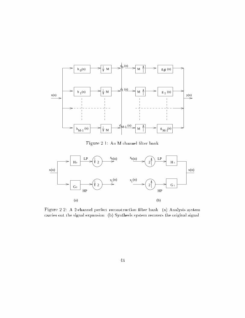
related [Dau92, RV91, VH92]. A generic structure of an M channel �lter
bank is shown in Figure 2.1, and a two channel �lter bank is shown in Figure
2.2.
42
M-1
h
h
0
1
(n)
(n)
h
M
M
M
M
M
M
g
0
d
d
d
0
1
M-1
(n)
(n)
(n)
y(n)x(n)
(n)0
(n)1
g
gM-1
(n)(n)
Figure 2.1: An M-channel �lter bank
2
2G
x
0
0H 2
2
1H
1G
LP
HP
LP
HP
x(n) x(n)
(b)(a)
1(n)x
1(n)x
0(n)x0(n)
Figure 2.2: A 2-channel perfect reconstruction �lter bank. (a) Analysis system
carries out the signal expansion. (b) Synthesis system recovers the original signal.
43
2.9 Wavelets, Filters and Multiresolution
The connection between multiresolution analysis and two-channel �lter banks
was described by Mallat [Mal89]. Daubechies exploited this connection to
construct the orthogonal wavelet bases of compact support.
The two-channel perfect reconstruction �lter bank [VH92, AS93] produces
a lowpass sequence x0 (n) and a highpass sequence x1(n) by passing the input
sequence x (n) through a half-band lowpass �lter H0 and a half-band high-
pass �lter H1 as shown in the analysis system of Figure 2.2(a). The original
sequence x (n) can be recovered from x0 (n) and x1 (n) by using them as inputs
to the synthesis system of Figure 2.2(b). The �ltering and downsampling
operators correspond to linear transformations. Conditions on H0 , H1 , G0
and G1 for the linear transformation to be orthogonal or biorthogonal are
well understood and described in [Vet87, Vai87].
The two-channel perfect reconstruction �lter bank can be iterated over
the lowpass to construct wavelet bases [Dau89, VH92]. The choice of �lters
for e�cient image coding has been studied and described in [Rio93].
44
2.10 Summary
This chapter describes the mathematical background to support the discus-
sions in the other chapters of the thesis. The Lesbegue measure theory is
intensively used in chapter 4 to describe our proposed class of image quality
measures. The functional analysis provides a necessary background for dis-
cussing quantisation techniques and fractal compression in chapter 3 and 5.
The multiresolution concept described in this chapter is important since it
provides an insight for further discussion of fractal and wavelet compression.
It allows us to see how fractal compression use coarse scale image features
to approximate �ne scale features. It also helps us understand the concept
of multiresolution in subband decomposition. More importantly, it bridges
the relation between fractal image compression and the wavelet analog to
fractal. The importance of digital �lters, particularly perfect reconstructed
�lters in image coding is seen by their relationship with subband and wavelet
based coding. The description of �lters in this chapter supports the discus-
sions of wavelet compression in chapter 3 and 5. In summary, this chapter
provides preliminary mathematical basis and theories required to present the
contributions of our work in the thesis.
45
Chapter 3
Image Compression and
Quality Evaluation
Research in image coding has explored various aspects of coding methods
such as image coding based on vector quantisation [HW85, HG88, CLG89,
CGG92, Mat92], image compression based on DCT [Wal91, WG93], wavelet-
based image compression [ABMD92, LK92, Sha93], fractal-based image cod-
ing [BS88, Jac90, Dud92, Fis95], etc. Today this �eld continues to grow at a
rapid pace and reports on new coders and variations to the existing ones are
appearing constantly in the literature. While image compression is growing
quickly due to its high demand for storage and transmission saving of high
volume image data, the evaluation of image quality has become more and
46
more important due to the increasing number of image applications and the
high demand for a better measure than the traditional mean-square-error to
test image systems such as image coding systems [MKA92, KGMA95], video
systems [CvdBL96]. This has lead to more research focus in this area aimed
at devising new image quality measures that can meet the above-mentioned
demand.
In this chapter, we survey the current research in image compression and
image quality evaluation areas. First, the three most active image compres-
sion areas, image coding with vector quantisation, fractal based image coding
and image compressed based on wavelet, are discussed. We then discuss the
problems with image quality evaluation and study the advantages and dis-
advantages of the existing methods. The survey will support the analysis,
discussion and comparison of image quality evaluation given in chapter 4,
and image compression in chapter 5 of the thesis.
3.1 Image Compression
Image data is large in size and hence requires more storage, processing and
transmission time. Research in image compression has been active for a
number of years and many image compression methods have been proposed.
The basic goal of image compression is to convert an original image into a
47
representation that can be digitally represented with as few bits as possible,
and the reproduction has the best possible quality. Images can be com-
pressed either by using lossless or lossy methods. With lossless compression,
the original image can be perfectly recovered from the digital representation,
and most lossless coding techniques are based on Hu�man [Huf77], adap-
tive Hu�man [Vit87], run-length [MR91], Ziv-Lempel [ZL77], and arithmetic
codes [RL77, WNC87].
Although with lossless compression, the original image can be perfectly
recovered from the digital representation, lossless compression cannot provide
high compression, and hence in many image applications (e.g., teleshopping,
telebrowsing systems, digital libraries, image databases) lossy compression
is needed. In general, the loss incurred in lossy compression is due to the
process called quantisation by which a large set of input values is represented
with a smaller set of values in order to reduce the size of the input data ob-
ject. In section 3.2, we describe quantisation techniques that are exploited
in many image coders. We then discuss the conventional transform coding
techniques in section 3.3. Finally, we discuss two current research areas in
image compression, viz., the wavelet in section 3.4 and fractal image com-
pression in section 3.5. This provides the necessary background for further
discussion of the proposed coding algorithms in chapter 5.
48

3.2 Image Compression With Vector Quanti-
sation
Image compression maps an original image into a new form of representa-
tion such that the number of bits required to represent the new form (coded
image) should be smaller than that required for the original image so that
less storage space or communication time will be needed. The lossless com-
pression refers to algorithms that allow the original pixel intensities to be
perfectly recovered from the compressed representation. Lossy compression
algorithms do not allow that. With lossy compression, the high rate digital
pixel intensities are mapped into a relatively small number of symbols. This
operation is non-linear and non-invertible, and hence it is lossy . The conver-
sion is called quantisation and it can operate on individual pixels or groups
of pixels. Quantisation can include throwing away some of the components
of the signal decomposition and hence the performance of a coder depends
on the quantisation.
Designing e�ective and e�cient quantisers is important in image com-
pression, since the design of a quantiser has a signi�cant impact on the
amount of compression obtained and loss incurred in a lossy compression
scheme [GG92]. A number of techniques have been proposed for e�ective
quantisation. The most basic one is the scalar quantisation. This technique
49
was used in early data coders and still e�ectively used in recently reported
image coders [LK92, ABMD92, Sha93, XRO94]. We brie y discuss scalar
quantisation as well as various vector quantisation techniques, lattice vector
quantisation, and the space-frequency quantisation method in the following
sections.
3.2.1 Scalar Quantisation
Quantisation in general is the process of mapping a larger set of values into
a smaller set of values by a quantiser. If the inputs and outputs of the quan-
tiser are scalar, then the process is called scalar quantisation (SQ).
In scalar quantisation, the inputs are individual real numbers which are of-
ten rounded to the nearest integers, called quantisation levels or reproduction
levels. If the output integers are evenly spaced, the quantisation is called
uniform quantisation. In general, the outputs need not be integers, nor are
they evenly spaced. The spacing between the quantisation levels is often
called the bin width. To specify a scalar quantiser, one needs to specify a
set of possible quantisation levels and a rule for mapping the inputs to the
quantisation levels.
An N-point scalar quantiser Qs can be de�ned as
Qs : R �! C
50
where R is the set of real numbers, and C is the set of N output values,
called the codebook . C is de�ned as
C = fyn;n = 1; 2; :::Ng� R
The mapping Qs partitions R into non-overlapping intervals (xi , xi+1 ) ac-
cording to the rule
if x 2 (xi ; xi+1 ) then
Qs(x) = yi
Although scalar quantisation is the simplest form of quantisations, in many
compression schemes, SQ is e�ectively used [JSM92, CK92, DJL92].
3.2.2 Vector Quantisation
Vector quantisation (VQ) is a generalisation of scalar quantisation. In scalar
quantisation an individual input value is coded by an index listed in a �xed
table of quantisation values. The idea that encoding a sequence of values
can provide an advantage over the encoding of individual samples was the
motivation for the study of vector quantisation. The study suggests that the
quantisation that works with sequences or blocks of values would provide
improvement in performance over scalar quantisation [NK88, GG92]. In VQ
the source output is grouped into blocks or vectors, and a vector of source
outputs forms the input to the vector quantiser. At both the encoder and
51
decoder of the vector quantizer, there is a set of vectors called the codebook
of the vector quantiser. The vectors in this codebook are called codevectors.
Formally, VQ can be described as follows:
Let x = (x1; x2; :::; xn) be a random vector of dimension n belonging to
Rn with probability function px(x) = px(x1; x2; :::; xn). A vector quantiser
Qv , of dimension n and size K , is de�ned as an application which associates
one of the K reproduction vectors with a vector x 2 Rn
Qv : Rn �! C
Qv is a function whose domain is the set of all possible values of x and whose
range, a codebook, is a set of K vectors
C = fy1;y2; :::;yKg � Rn
A VQ is therefore completely de�ned by the knowledge of the codebook and
a partition S = fS1; S2; :::; SKg of K regions in Rn such thati=KSi=1
Si = Rn
and Si
TSj = ; for i 6= j, where Si = fx 2 Rng such that
Qv(x) = yi; if Dm(x;yi) � Dm(x;yj) 8j 6= i (3.1)
where Dm(:; :) is a quality criterion or distortion measure, e.g., MSE.
Partition S for a given codebook is usually created using a classi�cation
algorithm and a training set. For instance, a vector x belonging to class
Si is represented by the vector yi belonging to the codebook. The distance
52
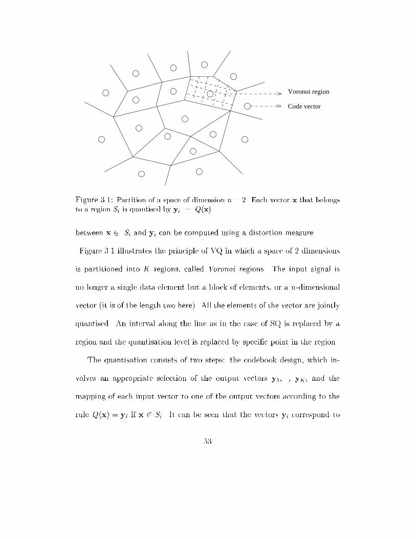
Code vector
Voronoi region
Figure 3.1: Partition of a space of dimension n = 2. Each vector x that belongs
to a region Si is quantised by yi = Q(x)
between x 2 Si and yi can be computed using a distortion measure.
Figure 3.1 illustrates the principle of VQ in which a space of 2 dimensions
is partitioned into K regions, called Voronoi regions. The input signal is
no longer a single data element but a block of elements, or a n-dimensional
vector (it is of the length two here). All the elements of the vector are jointly
quantised. An interval along the line as in the case of SQ is replaced by a
region and the quantisation level is replaced by speci�c point in the region.
The quantisation consists of two steps: the codebook design, which in-
volves an appropriate selection of the output vectors y1,..., yK , and the
mapping of each input vector to one of the output vectors according to the
rule Q(x) = yi if x 2 Si . It can be seen that the vectors yi correspond to
53
the quantisation levels in a scalar quantiser and the collection of quantisation
levels is referred to as the codebook.
There are a number of approaches to codebook design. The classical code-
book design approach is reported by Linde, Buzo and Gray [LBG80] and is
known as the LBG algorithm. This approach uses a long training sequence
of vectors whose members are �rst partitioned into a number of categories
equal to the required number of reproduction codewords. The second part of
the operation determines minimum distortion codewords for each category.
The algorithm can be iterated to minimise the overall distortion for a given
training sequence and the size of the codebook.
Many other algorithms such as the pairwise nearest neighbour, the Ko-
honen's self-organising maps and other neural network methods have been
applied to VQ design [GG92]. The comparison of the LBG and Kohonen's
neural network approaches was made by McAuli�e et al : [MAR90b]. It was
shown that the Kohonen's algorithm is relatively more tolerant to the use of
a poor initial codebook than the LBG algorithm. In addition, for an equiv-
alent distortion performance, fewer training vectors are needed. It is also
shown that the time for codebook generation can be reduced signi�cantly by
the use of a neural network approach to generate an initial codebook for the
LBG algorithm [GV90].
54
Another development in the codebook design area is the application of the
psycho-visual criteria. With this approach, the masking function (a weighted
sum of the horizontal and vertical luminance gradients) is used to account
for the the reduction in sensitivity of the human visual system to errors
[Mar91]. The use of two dimensional DCT to provide a feature domain for
the training partition [HLC91] and the in uence of training set size on algo-
rithm performance were also investigated [CPP+91]. Several other codebook
design approaches and the comparison of di�erent approaches were reported
in [GG92].
Since the performance of an image coding technique using VQ depends
on the performance of the vector quantiser, optimal VQ is expected to have
small codebook while still provides the best approximation. In VQ, the input
vector x, which consists of blocks of pixels, is quantised by being encoded into
a binary index in , which then serves as an index for the output reproduction
vector or codeword. If the code has a �xed rate of m then in has length m.
With a variable rate code, the indices in have variable length and m is their
average length. The compressed image is represented by these indices in , and
the compressed representation requires less bits than the original image.
The main goal in developing a vector quantiser is to �nd a codebook which
minimises the error according to a selected distortion criterion [BSG+93].
55
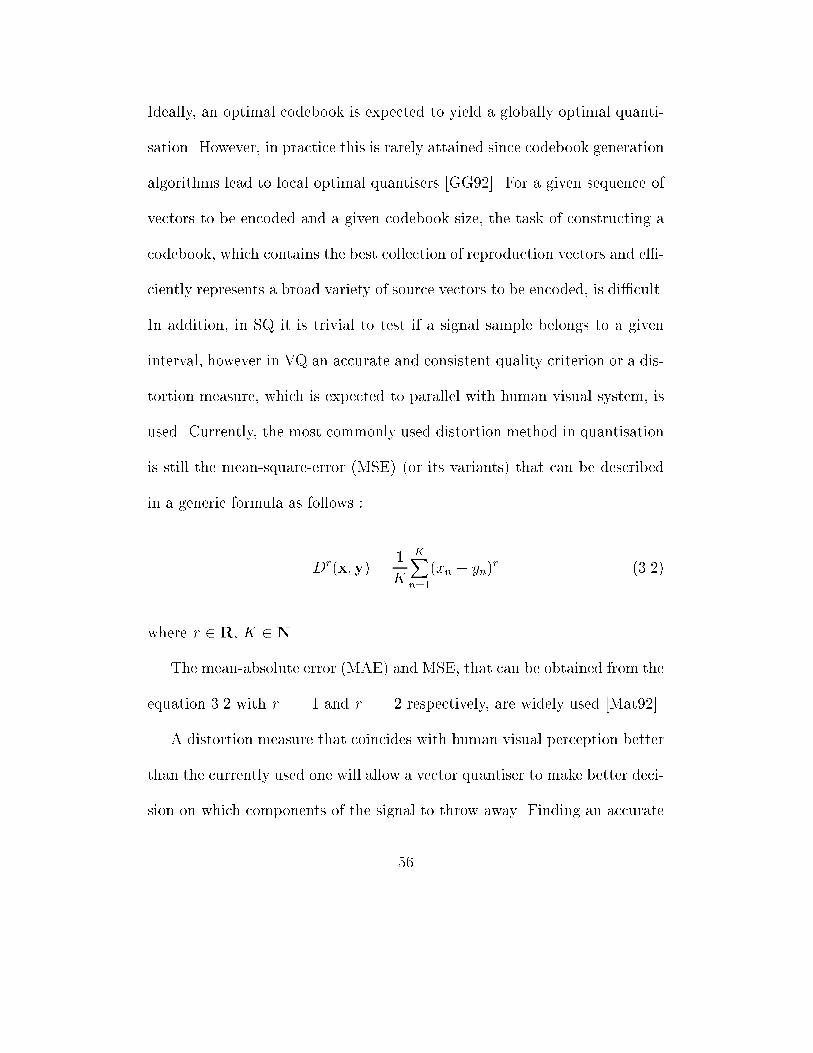
Ideally, an optimal codebook is expected to yield a globally optimal quanti-
sation. However, in practice this is rarely attained since codebook generation
algorithms lead to local optimal quantisers [GG92]. For a given sequence of
vectors to be encoded and a given codebook size, the task of constructing a
codebook, which contains the best collection of reproduction vectors and e�-
ciently represents a broad variety of source vectors to be encoded, is di�cult.
In addition, in SQ it is trivial to test if a signal sample belongs to a given
interval, however in VQ an accurate and consistent quality criterion or a dis-
tortion measure, which is expected to parallel with human visual system, is
used. Currently, the most commonly used distortion method in quantisation
is still the mean-square-error (MSE) (or its variants) that can be described
in a generic formula as follows :
Dr(x;y) =
1
K
KXn=1
(xn � yn)r (3.2)
where r 2 R, K 2 N.
The mean-absolute error (MAE) and MSE, that can be obtained from the
equation 3.2 with r = 1 and r = 2 respectively, are widely used [Mat92].
A distortion measure that coincides with human visual perception better
than the currently used one will allow a vector quantiser to make better deci-
sion on which components of the signal to throw away. Finding an accurate
56
distortion measure is one of the issues that VQ schemes have to deal with
and such an issue is still an open problem.
The general optimality of VQ over SQ was discussed by Gersho and Gray
in [GG92]. The application of VQ in several new image coders has also
shown its advantage over SQ [WBBW88, SG92]. The design of optimal VQ
codebook with minimum search time has lead to the development of di�er-
ent vector quantisation techniques that will be discussed in the rest of this
section.
1. Entropy constrained Vector Quantisation
The conventional VQ tries to minimise average distortion subject to
a constraint on the number of codewords. This is a suitable optimi-
sation formulation when the system is limited to a �xed rate and no
entropy coding takes place. However, it is more advantageous to de-
sign a quantiser with the entropy coding to minimise the distortion
subject to a constraint on the quantiser output entropy rather than on
the number of codewords. Entropy constrained VQ can improve rate-
distortion performance when a VQ is followed by an entropy coder,
but the price for the performance is at the expense of computational
complexity [CLG89].
57
2. Lattice Vector Quantisation
The entropy constrained VQ algorithm enables the creation of vector
quantisers with minimum distortion by imposing a constraint on the
entropy. However, �nding a set of reproduction vectors that minimise
the distortion and the average word length of a codebook is computa-
tionally expensive. In general, given an allowable number of codebook
entries, the generation algorithm will attempt to distribute them over
all the vectors of the training sequence in such a way as to minimise
some predetermined distortion function. The computational e�ort re-
quired to do this will increase exponentially with the codebook size.
Gersho [Ger79] suggested that codebook obtained by the use of the
entropy constrained VQ should take the form of a lattice (A lattice
in the Rn space is made up of independent vectors which cover the
entire space. The components of these vectors are obtained by linear
combinations of integer numbers). This has lead to the investigation
of lattice based VQ. The main advantage of lattice VQ over entropy
constrained is that in entropy constrained VQ the codebook is com-
puted using training sets, however, in lattice VQ this can be avoided
by a priori de�ning the codebook as a set of vectors that are regularly
distributed through out the space [JG89]. A further discussion of lat-
58
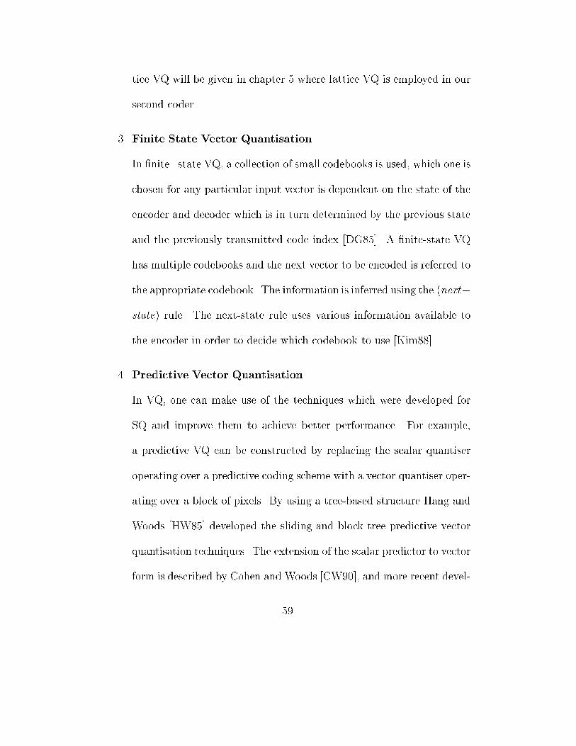
tice VQ will be given in chapter 5 where lattice VQ is employed in our
second coder.
3. Finite State Vector Quantisation
In �nite state VQ, a collection of small codebooks is used, which one is
chosen for any particular input vector is dependent on the state of the
encoder and decoder which is in turn determined by the previous state
and the previously transmitted code index [DG85]. A �nite-state VQ
has multiple codebooks and the next vector to be encoded is referred to
the appropriate codebook. The information is inferred using the (next�
state) rule. The next-state rule uses various information available to
the encoder in order to decide which codebook to use [Kim88].
4. Predictive Vector Quantisation
In VQ, one can make use of the techniques which were developed for
SQ and improve them to achieve better performance. For example,
a predictive VQ can be constructed by replacing the scalar quantiser
operating over a predictive coding scheme with a vector quantiser oper-
ating over a block of pixels. By using a tree-based structure Hang and
Woods [HW85] developed the sliding and block tree predictive vector
quantisation techniques. The extension of the scalar predictor to vector
form is described by Cohen and Woods [CW90], and more recent devel-
59
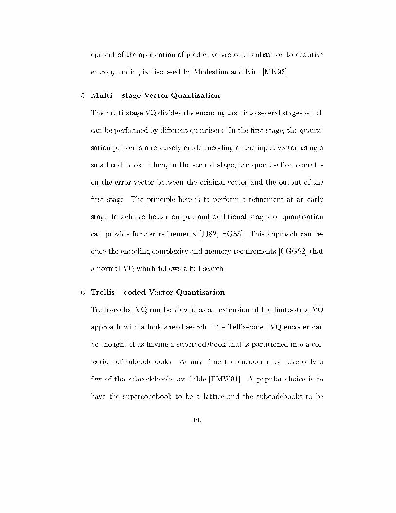
opment of the application of predictive vector quantisation to adaptive
entropy coding is discussed by Modestino and Kim [MK92].
5. Multi� stage Vector Quantisation
The multi-stage VQ divides the encoding task into several stages which
can be performed by di�erent quantisers. In the �rst stage, the quanti-
sation performs a relatively crude encoding of the input vector using a
small codebook. Then, in the second stage, the quantisation operates
on the error vector between the original vector and the output of the
�rst stage. The principle here is to perform a re�nement at an early
stage to achieve better output and additional stages of quantisation
can provide further re�nements [JJ82, HG88]. This approach can re-
duce the encoding complexity and memory requirements [CGG92] that
a normal VQ which follows a full search.
6. Trellis� coded Vector Quantisation
Trellis-coded VQ can be viewed as an extension of the �nite-state VQ
approach with a look ahead search. The Tellis-coded VQ encoder can
be thought of as having a supercodebook that is partitioned into a col-
lection of subcodebooks. At any time the encoder may have only a
few of the subcodebooks available [FMW91]. A popular choice is to
have the supercodebook to be a lattice and the subcodebooks to be
60
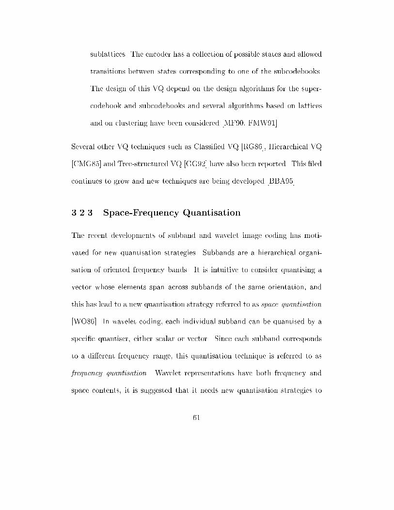
sublattices. The encoder has a collection of possible states and allowed
transitions between states corresponding to one of the subcodebooks.
The design of this VQ depend on the design algorithms for the super-
codebook and subcodebooks and several algorithms based on lattices
and on clustering have been considered [MF90, FMW91].
Several other VQ techniques such as Classi�ed VQ [RG86], Hierarchical VQ
[CMG85] and Tree-structured VQ [GG92] have also been reported. This �led
continues to grow and new techniques are being developed [BBA95].
3.2.3 Space-Frequency Quantisation
The recent developments of subband and wavelet image coding has moti-
vated for new quantisation strategies. Subbands are a hierarchical organi-
sation of oriented frequency bands. It is intuitive to consider quantising a
vector whose elements span across subbands of the same orientation, and
this has lead to a new quantisation strategy referred to as space quantisation
[WO86]. In wavelet coding, each individual subband can be quantised by a
speci�c quantiser, either scalar or vector. Since each subband corresponds
to a di�erent frequency range, this quantisation technique is referred to as
frequency quantisation. Wavelet representations have both frequency and
space contents, it is suggested that it needs new quantisation strategies to
61
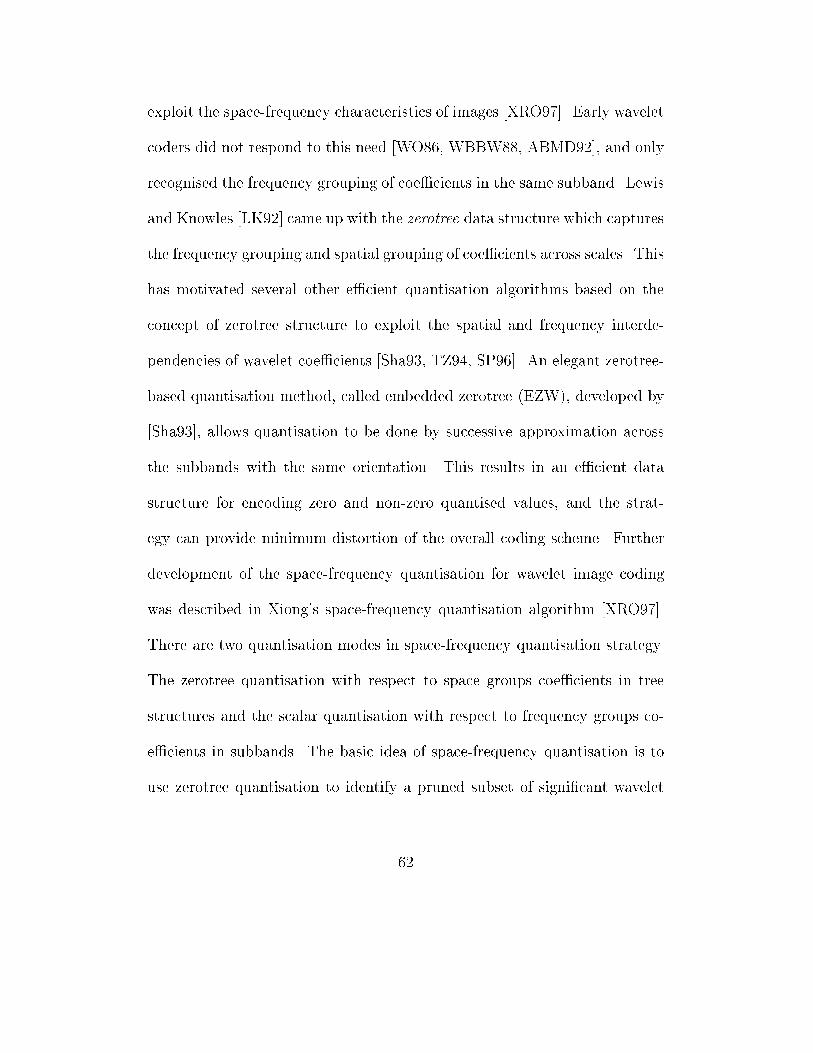
exploit the space-frequency characteristics of images [XRO97]. Early wavelet
coders did not respond to this need [WO86, WBBW88, ABMD92], and only
recognised the frequency grouping of coe�cients in the same subband. Lewis
and Knowles [LK92] came up with the zerotree data structure which captures
the frequency grouping and spatial grouping of coe�cients across scales. This
has motivated several other e�cient quantisation algorithms based on the
concept of zerotree structure to exploit the spatial and frequency interde-
pendencies of wavelet coe�cients [Sha93, TZ94, SP96]. An elegant zerotree-
based quantisation method, called embedded zerotree (EZW), developed by
[Sha93], allows quantisation to be done by successive approximation across
the subbands with the same orientation. This results in an e�cient data
structure for encoding zero and non-zero quantised values, and the strat-
egy can provide minimum distortion of the overall coding scheme. Further
development of the space-frequency quantisation for wavelet image coding
was described in Xiong's space-frequency quantisation algorithm [XRO97].
There are two quantisation modes in space-frequency quantisation strategy.
The zerotree quantisation with respect to space groups coe�cients in tree
structures and the scalar quantisation with respect to frequency groups co-
e�cients in subbands. The basic idea of space-frequency quantisation is to
use zerotree quantisation to identify a pruned subset of signi�cant wavelet
62
coe�cients for scalar quantisation (wavelet coe�cients can be organised into
a tree of coe�cients [Sha93, XRO97]), and throw away the insigni�cant co-
e�cients. Its goal is to jointly optimise the two quantisation modes, i.e., to
search for the optimal balance between choosing a large subset of coe�cients
to be quantised with low precision, or a small subset of coe�cients to be
quantised with high precision. The space-frequency quantisation algorithm
of [XRO97] achieves the above-mentioned joint optimisation in an operational
rate-distortion sense with a cost function J (�) = D + �R (where D is a
distortion measure, � is a Lagrange multiplier, and R is the allocated bits).
The MSE is used as the distortion measure. The �rst-order entropy is used
as the rate measure. Since the heart of the space-frequency quantisation is
the tree pruning phase which is used to �nd the best subset of coe�cients to
be quantised. The process starts with the full tree-structured set of wavelet
coe�cients. At each node of the tree, the decision is made if it is cheap to
keep or throw away all its descendent nodes using a cost function.
3.3 Transform Image Coding
Generally speaking, transform image compression algorithms can be split
into three parts: invertible transformation, lossy quantisation and entropy
coding. Figure 3.2 depicts a generic block-structured of transform image
63
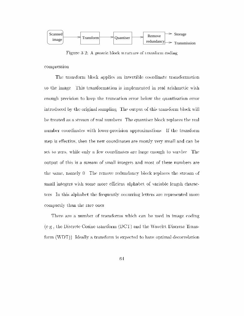
redundancyQuantiser
Scannedimage Transform Remove Storage
Transmission
Figure 3.2: A generic block structure of transform coding
compression.
The transform block applies an invertible coordinate transformation
to the image. This transformation is implemented in real arithmetic with
enough precision to keep the truncation error below the quantisation error
introduced by the original sampling. The output of this transform block will
be treated as a stream of real numbers. The quantiser block replaces the real
number coordinates with lower-precision approximations. If the transform
step is e�ective, then the new coordinates are mostly very small and can be
set to zero, while only a few coordinates are large enough to survive. The
output of this is a stream of small integers and most of these numbers are
the same, namely 0. The remove redundancy block replaces the stream of
small integers with some more e�cient alphabet of variable length charac-
ters. In this alphabet the frequently occurring letters are represented more
compactly than the rare ones.
There are a number of transforms which can be used in image coding
(e.g., the Discrete Cosine transform (DCT) and the Wavelet Discrete Trans-
form (WDT)). Ideally a transform is expected to have optimal decorrelation
64
e�ciency, image independence, and inexpensive computation. However, such
an ideal transform is still not available. The KLT is the optimal transform
in terms of its decorrelation e�ciency, however, it is image dependent and
obtaining the basis functions is a computationally expensive task. Research
attempts have been made to devise transforms that is computationally inex-
pensive, image independent and have near optimal decor-relation e�ciency
to KLT. The DCT derived from the fast Fourier transform is one of such
found transforms. DCT is computationally inexpensive and its e�ciency
approaches to that of KLT. DCT is used by the Joint Photographic Ex-
perts Group (JPEG) in the standard JPEG compression. JPEG applies
2-dimensional DCT to 8x8 disjoint subblocks of the image, followed by a
proprietary quantisation scheme on the DCT amplitudes, followed by either
Hu�man, Lempel Ziv Welch or arithmetic coding of the quantised coe�-
cients.
JPEG image compression based on DCT has become an international
standard for image compression. It is remarkably e�ective in reducing the
size of digitised image �les. However, it degrades ungracefully at high com-
pression ratios. At the compression ratios above 25 to 1, the blockiness
appears and this visible distortion becomes worse and worse at higher ratios.
To alleviate this problem, rather than using disjoint 8x8 subblocks, it is possi-
65
ble to use lapped orthogonal transforms (LOT) [Mal92b, Mal92a] or localised
cosine transforms (LCT) [AWW92] with overlapping patches of the image.
The use of LOT or LCT can reduce the blocking problem, however, there
is an increased computational complexity, a lower resolution, and possibly
increased severity of ringing artifacts 1 [PC91]. The blockiness and ringing
problems can be eased with recent research in image compression based on
wavelets that will be discussed in detail in the next section.
3.4 Image Compression with Wavelets
Since the introduction of wavelets as a signal processing tool in the late
1980s, considerable attention has been focused on the application of wavelets
to image compression [WO86, ABMD92, LK92, Sha93]. There has been in-
creasing number of reports each year on the design of new wavelet coders and
variations to existing ones. Basically wavelet image encoding scheme follows
a standard well-understood transform coding paradigm. First an invertible
wavelet transform is performed on an image, then the transform coe�cients
are quantised, entropy coded and stored. However, wavelet transform of an
image is a multiresolution and multi-scale representation of that image. The
1Ringing noise is the artifact experienced in traditional subband coders which employ
�lter banks with long unit pulse responses. The noise is generated in region with sharp
transitions.
66
resolution of an image is related to the bandwidth or frequency of the sig-
nal. As the resolution increases, the amount of detail visible in the image
increases. The scale of an image is related to the size or length of the signal.
At large scales, the signal is contracted. At small scales, the signal is dilated.
Wavelet representations di�er in their choice and the three most impor-
tant classes of wavelets are orthogonal wavelets, biorthogonal wavelets and
wavelet packets.
Orthogonal wavelets are the family of wavelets that generate orthogonal
bases of L2(Rn). Among them the most important ones to image compres-
sion are compactly supported orthogonal wavelets [Dau88]. The compactly
supported orthogonal wavelets are important to image coding, since in the
discrete wavelet transform (DWT), compactly supported wavelets correspond
to FIR �lters and thus lead to e�cient implementations.
The development of a systematic way for constructing compactly sup-
ported wavelets [Dau93b, Dau93a] and fast algorithms for computing DWTs
[BCR91, RD92] has made it applicable in image coding. For compactly sup-
ported wavelets, a family of wavelets is parameterised by an integer that is
proportional to the length of the wavelet �lter, and the length of a wavelet
�lter is proportional to the degree of smoothness and regularity of the wavelet
which can a�ect the coding performance. However, it has been shown that for
67
�lter lengths greater than 10, the gain in compression performance is nom-
inal and not worth the additional computational cost [ZHL90, Rio93]. The
disadvantage of compactly supported wavelets is their asymmetry because
this property translates into nonlinear phase in the associated FIR �lters,
and in computing DWT using nonlinear phase wavelet �lters, artifacts at
the borders of the wavelet subbands can occur, and this has lead to the use
of biorthogonal wavelets in image coding [CDF92, CAS+92]. The preference
of biorthogonal wavelets over the orthogonal wavelets is to avoid possible
artifacts at the borders of wavelet subbands.
The introduction of wavelet packets to image processing has opened a
new avenue for image compression, since from a rich library of orthonormal
bases, a best wavelet transform can be chosen to match the frequency and
spatial characteristics of a given image, hence possibly better compression
can be obtained [Uhl94, Uhl95].
The wavelet packets allow the best possible wavelet transform to be se-
lected for the best coding performance of a given image. This requires an in-
tensive search through all the possible wallet packets in the library, hence fast
search algorithms are needed. A fast search algorithm for the best wavelet
transform based on tree structure was proposed by Coifman [CW92], and a
further development based on the rate distortion operation was proposed by
68
Ramchandran and Vetterli [RV93]. However, this only reduces partially the
search time.
Another development in wavelet research, which is applicable to image
compression, is the design and analysis of multiwavelets. Multiwavelets de-
note multiple wavelets whose dilations and translations collectively generate
an orthogonal basis of L2(Rn). Compared with single wavelets, orthogonal
multiwavelets can be shorter, with more vanishing moments and symmetric,
hence they can better represent images [SS94].
Under certain conditions, an image can be e�ectively represented by
the zero-crossings of the wavelet transform [Mal91] or local maxima of the
wavelet transform modulus [MZ92]. When wavelets are carefully chosen as
a smoothed gradient operator, the zero-crossings and local maxima of corre-
sponding wavelet transforms can be interpreted as multi-scale edges. Gener-
ally speaking, a non-orthogonal wavelet is required for this purpose and the
resulting wavelet transform of the image is oversampled in space before the
extraction of the zero-crossings and local maxima. Image coding using zero-
crossings and local maxima was demonstrated by Mallat [MZ90] and Mallat
and Zhong [MZ91]. The later was re�ned by Froment and Mallat [FM92] and
linked to the second generation image coding techniques [RMB97] that use
image features such as contours, as coding primitives. A more recent coding
69
system along with this line was developed by Croft and Robinson [CR94].
These feature-based image coding systems usually require non-conventional
quantisation and coding techniques. For example, in the wavelet local max-
ima representation, coding performance would be better if quantisation is
done on the chains of local maxima, edges contours, instead of individual
local maxima. The quantised chains of wavelet local maxima can then be
encoded with a contour coder [MZ90].
3.5 Fractal Image Compression
Fractal image compression possesses the following properties:
(i) A mathematical space X of real world images has to be de�ned. Each
point in this space represents a real world image.
(ii) A metric d on the space X must be found such that (X,d) is a complete
metric space.
(iii) A contractive map f which acts upon (X,d) and satis�es the following
condition :
d(f (x); f (y)) � c:d(x; y) 8x; y 2 X, and
0 � c < 1, and c 2 R.
The encoding and decoding processes are basically based on the �xed
point and collage theorems and the most popular fractal image compression
70
scheme can be described as follows.
The image is partitioned into non-overlapping range blocks. For every
range block a larger domain block, which can be best transformed to the
range block by some map, is sought. The mapping of the domain block to
the range block is recorded, and hence the set of found maps is the encoding
of the image.
The decoding proceeds as follows. The maps are applied to an arbitrarily
initial image, and the process is repeated. Provided the maps are contractive,
the sequence of images produced by the iterations will converge to a stable
image, approximating the original picture. In general, a simple fractal block
coder as described by Jacquin [Jac92] can be described as follows:
Let I be the image to be encoded, for simplicity assume that I is of
2N � 2N ; BJK;L denotes a block of size J with lower left corner at (K ;L).
I is partitioned into a set of non-overlapping 2R � 2R range blocks
fBRK;L j (K;L) 2 Rg, where R = f(2Rm; 2Rn) j 0 � m;n < 2N�Rg. The
domain blocks from which the codebook is constructed are drawn from the
domain pool, the set fBDK;L j (K;L) 2 Dg, where the domain pool D can be
de�ned as D = f(2Dm; 2Dn) j 0 � m;n < 2N�Dg 2. The two basic operators
often used for codebook construction are the averaging and subsampling oper-
2There is a variety of domain pools used in the literature [Jac92, Fis95].
71
ator A and the symmetry operator O. A maps a 2Jx2J block to a 2J�1x2J�1
by averaging each pixel in 2Jx2J with its neighbors and then subsampling.
The O operator maps a square block to one of 8 isometries obtained from
compositions of re ections and 90 degree rotations. Range blocks are quan-
tised to a linear combination of an element from the codebook and a constant
block. The codebook used for quantising range blocks consists of averaged
and subsampled isometries of domain blocks. The codebook can then be
described as the set C = fOkAD�RBD
K;L : (K;L) 2 D; 0 � k � 8g. Here
AD�R denotes the operator A applied D � R times. The contrast of the
codewords in C is adjusted by a factor g , and the DC component is adjusted
by adding a subblock of the 2J�1x2J�1 matrix of ones ([1]: the unit vector),
multiplied by an o�set factor h. The approximation of each range block is
described as follows:
BR� � g�OP (�)A
D�RBD�(�) + hBR
� [1] (3.3)
where �: R ! D assigns an element from the domain pool to each range
block, and P :! f1:::8g assigns each range b lock a symmetry operator index.
Since the number of domains can be large and for each range the search
for a domain which best matches the given range must be carried out, hence
the encoding process is time consuming. To reduce the coding time several
72
approaches were devised.
1. Domain blocks can be classi�ed into classes [Jac92, Fis95], and the
search for a domain which sub-optimally matches a given range can be
done by only searching domains in a particular category. This reduces
searching time but can reduce the quality of the reconstructed image
too.
2. Domain blocks can be arranged in some data structure which can speed
up the search [BE95], [Sau95].
3. Rendering range blocks by approximation [MD92, Dud92]. This ap-
proach subdivides the image into blocks of the same size and tiles each
block with reduced copies of itself using a least square criterion to
derive an optimal mapping. A generalisation of this approach is the
Bath Fractal Transform (BFT) [MW94]. The BFT method allows a
block to be approximated and hence searching can be avoided. Since
the matching search is avoided images can be approximated with lin-
ear computational complexity, however this approach does not achieve
high compression.
73
3.5.1 Fractal Image Compression versus Other Com-
pressions
Fractal image compression techniques are the product of the study of iter-
ative function systems (IFS) [BJ88, Jac90]. Fractal compression techniques
involve an approach which is quite di�erent from standard transform meth-
ods such as JPEG. Transform image compression methods model images in
a simple fashion as vectors drawn from a stationary random process. They
store image as quantised transform coe�cients. Transform coders are de-
signed to take advantage of simple structure in images, namely that values
of pixels that are close together are correlated. Fractal image compression is
motivated by the observation that important image features such as straight
edges and constant regions are invariant under rescaling. Constant gradi-
ents are covariant under rescaling, that is rescaling changes the gradient by
a constant factor. Scale invariant presents an additional type of structure
for an image coder to exploit. Fractal image compression takes advantage of
this local scale invariant by using coarse scale image features to quantise �ne
scale features. In other words, fractal compression techniques assume that
image redundancy can be e�ciently exploited through self -transformability
[Jac92]. They store images as contraction maps of which the images are
approximate �xed points. In decoding compressed images, these maps are
74
applied to any image iteratively, and the original images are approximately
reconstructed.
First, fractal image compression is viewed as a product of IFS. Originally
such systems were introduced by Hutchinson [Hut81]. This motivated Barns-
ley [BJ88, BS88] to search for an image compression system that models real
world images as attractors of IFSs. This work was continued by Jacquin with
an important modi�cation of IFSs with the idea that the maps of IFSs have
domains that covered only part of the image. His �rst implementation of the
idea [Jac90] has brought fractal image compression to practice, and hence
such IFSs were called local [BH93] or partition [Fis95].
It is also possible to view fractal image compression as self vector quan-
tisation. This is because the basic fractal image compression can be seen as
a particular type of vector quantisation coding [RL93]. The possible di�er-
ence between the two techniques is with fractal compression the codebook is
not explicitly available at the decoder but rather given implicitly in a self-
referential manner.
Since fractal image compression uses the property of self-similarity at dif-
ferent scales, it is natural to use multiresolution methods for an analysis of
fractal coding. The �rst approach in this direction was discussed in [BMK93],
and explicit formulations of fractal coding by means of wavelet analysis were
75
given in the papers of Simon [Sim95] and Davis [Dav95].
Fractal block based coding can also be related to VQ based coding. Frac-
tal block coders perform a vector quantisation (VQ) of image blocks. The
vector codebook is constructed from locally averaged and subsampled isome-
tries of larger blocks from the image [Jac92]. This codebook is e�ective for
coding constant regions and straight edges due to the scale invariance of these
features. The vector quantisation is done in such a way that it determines a
contraction map from the plane to itself of which the image to be encoded
is an approximate �xed point. Encoded images are stored by saving the pa-
rameters of this map and decoded by applying the map iterively to �nd its
�xed point. The advantage of fractal block coding over Vector Quantisation
is that it does not require separate storage of a �xed vector codebook.
3.5.2 Fractal-Wavelet Based Image Coding
One of the recent developments in fractal analysis and coding is the relation-
ship between wavelet and fractal theory. The self-similarity property existing
in signals can be represented by both fractal and wavelet analysis. Bogdan's
[Bog95] work on the extension of the iterated transform theory (ITT) has
provided a framework for relating the similarities between ITT and wavelet
theory. With a scale of two, the wavelet decomposition of a function f can
76
be expressed as
f (x) =X
cif(2x� bi) (3.4)
where ci are the basis function coe�cients and bi are the translation terms.
This equation is related to the a�ne equation usually employed in fractal
coding, where ci and bi are the contrast-scaling and brightness-o�sets pa-
rameters respectively [Fis95]. This similarity was also independently consid-
ered by Simon [Sim95] who compared the similarities between the wavelet
multiresolutional representation and hierarchical fractal decoding.
There are coders that combine fractal and wavelet coding [RC95, Dav95].
One of the possible combinations is to apply fractal coding procedure on
wavelet coe�cients. The wavelet coe�cients are grouped for the range and
domain blocks and then the fractal coding is applied. It was shown by Davis
[Dav95] that high compression results can be obtained with image compres-
sion based on this approach.
3.6 Image Quality Evaluation
In several image processing applications, particularly in image compression,
images are modi�ed to reduce storage requirements or communication costs.
77
The evaluation of lossless compression techniques is normally a simple and
straightforward task, where a number of standard criteria such as compres-
sion ratio, execution time, are employed. For lossy image compression tech-
niques, the task is much more di�cult, since describing the type and amount
of degradation in reconstructed images is di�cult. In lossy image compres-
sion, a reconstructed image is often compared to the original in order to �nd
how much distortion has occurred or how much quality has been lost.
The importance of image quality evaluation has been recognised for many
years and the need for an accurate image quality measure is more urgent in
the recent years due the growing number of multimedia, image and video
applications [CGV96, OMM96].
Generally there are two approaches for determining image quality, the
subjective and objective approaches. Subjective image quality evaluation
requires a group of viewers to rate a set of modi�ed images in comparison
to their originals. Objective image quality assessment determines quality
of an image by a computational process that maps a modi�ed image to a
value which is compared to the value of the original. The development of
an image quality measure that is perceptually meaningful, applicable, and
with acceptable computational complexity is an important research. This is
because, besides its use in lossy image compression, there is an increasing
78
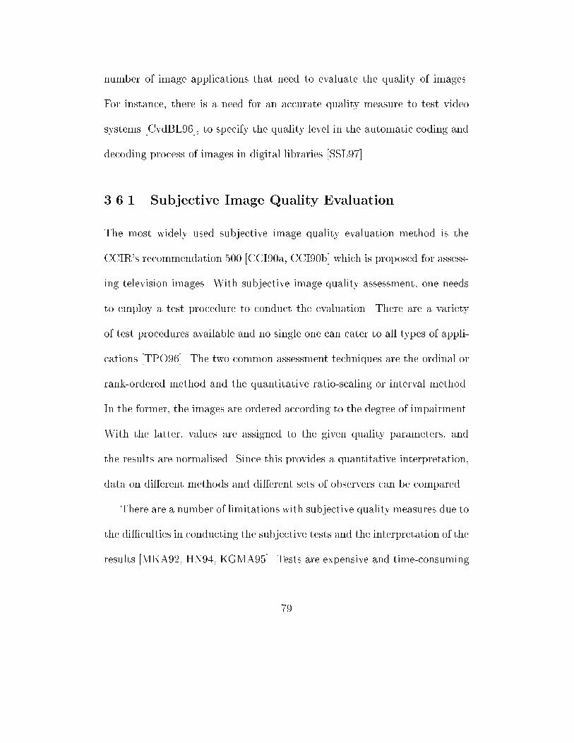
number of image applications that need to evaluate the quality of images.
For instance, there is a need for an accurate quality measure to test video
systems [CvdBL96], to specify the quality level in the automatic coding and
decoding process of images in digital libraries [SSL97].
3.6.1 Subjective Image Quality Evaluation
The most widely used subjective image quality evaluation method is the
CCIR's recommendation 500 [CCI90a, CCI90b] which is proposed for assess-
ing television images. With subjective image quality assessment, one needs
to employ a test procedure to conduct the evaluation. There are a variety
of test procedures available and no single one can cater to all types of appli-
cations [TPO96]. The two common assessment techniques are the ordinal or
rank-ordered method and the quantitative ratio-scaling or interval method.
In the former, the images are ordered according to the degree of impairment.
With the latter, values are assigned to the given quality parameters, and
the results are normalised. Since this provides a quantitative interpretation,
data on di�erent methods and di�erent sets of observers can be compared.
There are a number of limitations with subjective quality measures due to
the di�culties in conducting the subjective tests and the interpretation of the
results [MKA92, HN94, KGMA95]. Tests are expensive and time-consuming
79
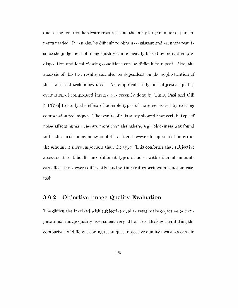
due to the required hardware resources and the fairly large number of partici-
pants needed. It can also be di�cult to obtain consistent and accurate results
since the judgement of image quality can be heavily biased by individual pre-
disposition and ideal viewing conditions can be di�cult to repeat. Also, the
analysis of the test results can also be dependent on the sophistication of
the statistical techniques used. An empirical study on subjective quality
evaluation of compressed images was recently done by Timo, Pasi and Olli
[TPO96] to study the e�ect of possible types of noise generated by existing
compression techniques. The results of this study showed that certain type of
noise a�ects human viewers more than the others, e.g., blockiness was found
to be the most annoying type of distortion, however for quantisation errors
the amount is more important than the type. This conforms that subjective
assessment is di�cult since di�erent types of noise with di�erent amounts
can a�ect the viewers di�erently, and setting test experiments is not an easy
task.
3.6.2 Objective Image Quality Evaluation
The di�culties involved with subjective quality tests make objective or com-
putational image quality assessment very attractive. Besides facilitating the
comparison of di�erent coding techniques, objective quality measures can aid
80
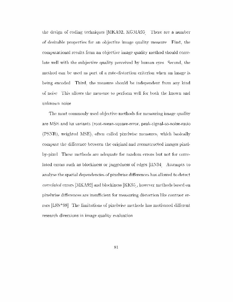
the design of coding techniques [MKA92, KGMA95]. There are a number
of desirable properties for an objective image quality measure. First, the
computational results from an objective image quality method should corre-
late well with the subjective quality perceived by human eyes. Second, the
method can be used as part of a rate-distortion criterion when an image is
being encoded. Third, the measure should be independent from any kind
of noise. This allows the measure to perform well for both the known and
unknown noise.
The most commonly used objective methods for measuring image quality
are MSE and its variants (root-mean-square-error, peak-signal-to-noise-ratio
(PSNR), weighted MSE), often called pixelwise measures, which basically
compute the di�erence between the original and reconstructed images pixel-
by-pixel. These methods are adequate for random errors but not for corre-
lated errors such as blockiness or jaggedness of edges [HN94]. Attempts to
analyse the spatial dependencies of pixelwise di�erences has allowed to detect
correlated errors [MKA92] and blockiness [KK95], however methods based on
pixelwise di�erences are insu�cient for measuring distortion like contrast er-
rors [LSS+98]. The limitations of pixelwise methods has motivated di�erent
research directions in image quality evaluation.
81
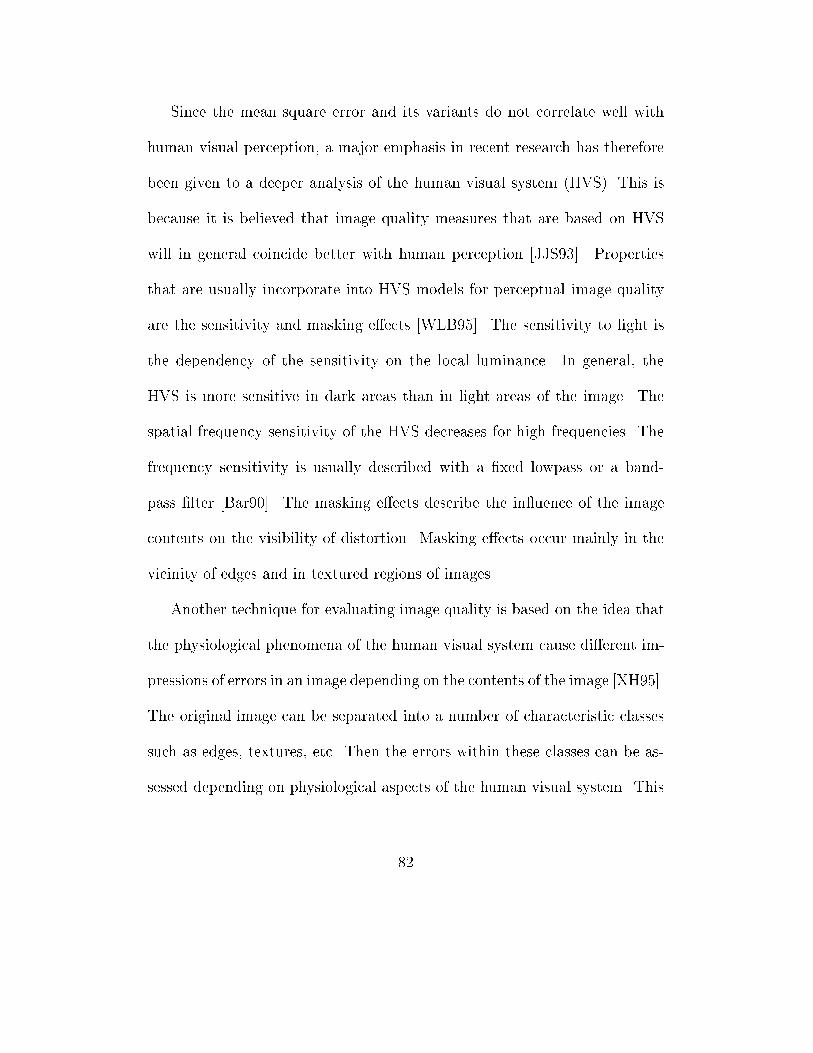
Since the mean square error and its variants do not correlate well with
human visual perception, a major emphasis in recent research has therefore
been given to a deeper analysis of the human visual system (HVS). This is
because it is believed that image quality measures that are based on HVS
will in general coincide better with human perception [JJS93]. Properties
that are usually incorporate into HVS models for perceptual image quality
are the sensitivity and masking e�ects [WLB95]. The sensitivity to light is
the dependency of the sensitivity on the local luminance. In general, the
HVS is more sensitive in dark areas than in light areas of the image. The
spatial frequency sensitivity of the HVS decreases for high frequencies. The
frequency sensitivity is usually described with a �xed lowpass or a band-
pass �lter [Bar90]. The masking e�ects describe the in uence of the image
contents on the visibility of distortion. Masking e�ects occur mainly in the
vicinity of edges and in textured regions of images.
Another technique for evaluating image quality is based on the idea that
the physiological phenomena of the human visual system cause di�erent im-
pressions of errors in an image depending on the contents of the image [XH95].
The original image can be separated into a number of characteristic classes
such as edges, textures, etc. Then the errors within these classes can be as-
sessed depending on physiological aspects of the human visual system. This
82
idea was implemented by Bock, Walter and Wilde [BWW96]. The original
image is separated into three classes of characteristics, textures, edges and
at regions. The errors in each class is then assessed according to some cri-
teria, e.g., edges are considered as more important features of an image since
they represent the visual separation of the objects. The error sums of each
class is globally weighted according to human perception.
One of the HVS based quality measure techniques that seriously takes
into consideration of the fact that HVS is not equally sensitive to various
types of distortion in a modi�ed image is the Picture Quality Scale (PQS)
method [MKA92, KGMA95]. This method is based on the quantitative mea-
sures of �ve distortion factors which are considered to be correlated and they
are:
1. Distortion factor 1 is a weighted di�erence between the original and
compressed images. The weighting function is adopted from the CCIR
television noise weighting standard with modi�cation.
2. Distortion factor 2 is also a weighted di�erence between the original and
compressed images, however the weighting function is from a model
of HVS. An indication function is also included to account for the
perceptual threshold of visibility.
83
3. Distortion factor 3 re ects the end of block disturbances. This aims
to capture the blocking artifacts which are generated by certain block
coders.
4. Distortion factor 4 accounts for correlated errors such as textures.
5. Distortion factor 5 is used to measure all disturbances in the vicinity of
high contrast transitions, e.g., visual masking and enhanced visibility
of misalignments which in turn refers to the visibility of noise decreases,
and the visibility of misalignments increases.
A principal component analysis is carried out to transform these distortion
factors into uncorrelated things called sources of errors, and then dominant
sources are identi�ed. Finally these errors are mapped to a PQS value by
a model which is obtained from a linear regression analysis with the Mean
Opinion Score (MOS).
A di�erent approach for image quality evaluation is the colour-based tech-
nique [ASB96]. The basic idea of this approach is that the colour is one of
the criteria used by human eyes to identify objects, hence the data loss of an
image can be quanti�ed by using a colour histogram. The colour histogram
of an image is a series of bins representing the di�erent colours in an image.
Each bin contains the number of pixels in the image that have that colour.
This technique evaluates the quality of a compressed image by calculating
84
the di�erence between the corresponding bins of the colour histograms of the
original and compressed images.
In general an image quality measure should be independent from the fac-
tors such as compression methods used, basic image processing operations
like colour adjustment, viewing distance, and di�erent types of noise.
3.7 Conclusion
Future information systems will inevitably be multimedia. Such information
systems not only have to handle text and numeric data but also large amount
of image data. The growing number of image applications indicates that im-
age data will grow quickly and this creates a high space requirement. The
long delay that Internet users currently experience shows that the existing
networks are not advanced enough to provide better bandwidth to allow the
increasing amount of requested data to be transmitted across the networks
without unacceptable delays. This has made the demand for high compres-
sion methods in order to reduce space requirement and transmission time.
While the search for high image compressions is important, the demand
for an accurate and consistent method for evaluating the quality of modi�ed
images is also an important requirement. Since multimedia systems and im-
age databases may have to store compressed images which are compressed
85
by a lossy compression technique, the quality of compressed images need
to be evaluated in order to know if compressed images will satisfy future
requirements. The emergence of digital video technology has also put an ur-
gent demand for an accurate image quality measure. This is because testing
a digital video system requires to evaluate the quality of motion rendition
[CvdBL96].
This chapter has discussed the importance of high lossy image compres-
sion and image quality evaluation methods. The survey of three most active
image compression approaches was given to support further discussion in
the later chapters. Di�erent quantisation methods were described and their
applications in wavelet based image compression will be further discussed in
chapter 5. Both fractal and wavelet based compression techniques can lead to
the discovery of high image compression techniques. The evolution of fractal
image compression has shown that the domain range matching search can
be alleviated with techniques such as classi�cation, clustering. However, the
gain in speed does pay for the price of loss in quality. The survey of wavelet
based image coding shows that this approach can achieve high compression.
In addition, the discovery of wavelet packets can lead to high image com-
pression [XRO94, RXAV96]. The analog between fractal and wavelet based
image coding also opens an interesting research area [Sim95, Dav96]. Both
86

wavelet packet based and fractal-wavelet based methods will be exploited
in chapter 5 where the image quality evaluation plays an important role in
improving image coding to achieve high compression.
87
Chapter 4
A New Class of Objective
Image Quality Measures
4.1 Introduction
The evaluation of image quality is important in many image processing ap-
plications. Reliable and economic methods for assessing image quality are
essential for designing better imaging systems [MKA92, KGMA95], and for
testing digital video communication systems [CvdBL96].
Image quality can be evaluated either by subjective or objective methods.
Subjective image quality measures are widely used to evaluate the quality
of images in a number of image applications such as in television and video
88
systems and in image enlargement. However, careful subjective assessment
of image quality is experimentally di�cult, lengthy and the results may vary
depending on the test conditions. In addition, it is not feasible to apply sub-
jective image quality assessment to �ne-tune image compression during the
coding process. It is also not possible to employ it to automatically coding
and decoding images at a speci�ed quality level.
The disadvantages of subjective image quality evaluation approach has
motivated for objective image quality measures. The most commonly used
methods for measuring the quality of a modi�ed image against the original
image are the mean-square-error (MSE) measure and its variants. However,
these methods do not coincide with the visual quality of the images very well
[Ber93, LSS+98]. They are good distortion indicators for random errors, but
not for structured or correlated errors.
There are also other proposed techniques for measuring image quality.
These techniques attempt to detect some of the known noise generated
by some compression algorithms such as blockiness, blurring, jaggedness of
edges, contrast errors or quantisation e�ect [HN94, KK95]. The most thor-
ough attempt to measure the overall distortion is the Picture Quality Scale
(PQS) [MKA92, KGMA95]. However, as other methods it has its drawbacks,
viz., the measure operates on pixelwise di�erences. Also it was designed us-
89
ing prior knowledge of the existing compression algorithms. Thus it may
perform poorly in the case of compression artifacts that were not considered.
Although, there are a number of proposed image quality measures, none
of the reported methods give the correct answer for all cases. Assessing the
quality of modi�ed images reliably is still an open problem [DPTI96]. There
are at least two factors which contribute to the di�culty of �nding a complete
image quality measure algorithm:
1. There are di�erent kinds of noise and each can a�ect the quality of the
image di�erently.
2. It is not simple to mathematically prove the quality of an image without
human judgement.
This chapter �rst de�nes image quality assessment as a positive real value
function and describes the criteria for image quality evaluation. It then
proposes a new class of objective image quality measures. Finally, the ex-
periments together with the results and the comparison with other methods
and the analysis of the methodology are presented.
Since image quality and distortion methods are often used interchange-
ably in image processing research community, we formally de�ne image qual-
ity measure as a real inverse function of the error function. This will be useful
for any objective measure, since basically objective image quality measures
90
are computational methods which determine quality of a modi�ed image by
a computational process that maps the image to a value which is compared
to the value of its original image.
First we de�ne the error function as follows:
Ef (g) : f � (H (X); dh)�!R�0 (4.1)
where (H (X),dh) is the space of all real world images, g is the modi�ed image,
f is the original image (f ; g 2 (H (X ); dh). The value of Ef (g) indicates the
error when the modi�ed image g is compared to its original f .
The quality function is de�ned as
Qf (g) =
8<:
1Ef (g)
; if Ef (g) 6= 0 ;
+1; otherwise.
(4.2)
The value Qf (g) indicates the quality of the modi�ed image g with respect
to its original f .
The MSE and its variants can be classi�ed as pixelwise image distortion
measures as they operate on individual pixel units, and this class of distortion
methods can be de�ned by
k f � g kLp(A) =�Z
Ajf(x)� g(x)jpdx
� 1
p
(4.3)
91
where 0 < p < 1,RA denotes the Lebesgue integral on a measurable set A,
Lp(A) denotes the space of p-Lebesgue integrable functions (refer chapter 2).
This class of measures, including the mean-absolute (when p = 1) and
mean-square (when p = 2) errors as special cases, gives much exibility for
selecting a quality or an error measure.
In general, image error measures use as their basis the residue image,
that is, the modi�ed image subtracted from or compared to the original by
some mathematical means. All the measures try to map the residue image
to some quantity that is expected to have the following properties:
1. The error function is not negative, Ef (g) � 0,
2. Zero only when the original and modi�ed images are identical, Ef (g) =
0 if and only if g = f , and
3. Monotonically increasing as the modi�ed image looks worse, i.e., if
Ef (g1 ) < Ef (g2 ), then visually g1 looks better than g2 .
There are a number of other desirable properties for an objective image
quality measure. First, the computational results from an objective image
quality method should correlate well with the subjective quality perceived
by human eyes. Second, the method can be used as part of a rate-distortion
criterion when an image is being encoded. Third, the measure should be
92
independent from any kind of noise. This allows the measure to perform well
for both the known and unknown noise.
Our study of the existing image quality measures and the e�ect of di�erent
possible types of noise has motivated us to propose a new class of objective
quality measures that will be described in the following section.
4.2 New Class of Objective Image Quality
Measures
The main advantage of the MSE and its variants is their low computational
complexity, simplicity and their ability to capture random noise. However,
the well-known disadvantages of these measures are that they do not coincide
with human visual perception very well and they fail to capture structured
errors or correlated errors. These weaknesses result from the choice of fun-
damental units in computing the errors. Image quality evaluation methods
based on individual pixel computation do not parallel with human eyes. We
argue that perceptually when two images (the modi�ed and original images)
are compared, human eyes are more sensitive to noise occurred concentrat-
edly in one small area than randomly distributed in the image. This can be
visually seen in the two images of Lena in Figures 4.1 and 4.2.
93
In Figure 4.1, Lena's image is modi�ed with noise inserted randomly,
and in Figure 4.2 noise is inserted into Lena's image in one small area on her
hat. In both cases the same number of pixels are changed by reducing their
corresponding pixel values by 30. Lena's image in Figure 4.1 looks almost
the same as its original, however one can easily identify a square dark area on
the hat in Figure 4.2. The MSE and its variants fail to give the correct val-
ues in this case. The PSNR values of these two images indicate that Lena's
image in Figure 4.2 (PSNR = 40.95) should look better than Lena's image
in Figure 4.1 (PSNR = 40.73), however, visually this is not true.
We propose a methodology for image quality evaluation which is based
on the following principles:
1. Since the quality of a modi�ed image is evaluated against the origi-
nal, it has to be normalised to the original image for more accurate
comparison.
2. The quality of an image should be measured locally and globally. This
implies that:
(a) The change of each pixel value �rst a�ects the quality of a small
part of the image that directly contains the pixel (the size of the
small part is often big enough for human eyes to identify the error),
and the change of that part of the image a�ects the quality of the
94

Figure 4.1: Lena's image with the insertion of noise, 1600 pixels are randomly
subtracted by 30 (PSNR = 40.73)
Figure 4.2: Lena's image with the insertion of noise, 1600 pixels in the hat area
are subtracted by 30 (PSNR = 40.95)
95
whole image. This suggests that image quality should be evaluated
part by part rather than pixel by pixel. The units used should
be larger than the individual pixels since human eyes are more
sensitive to correlated errors than randomly distributed errors as
mentioned above.
(b) Since the change of each pixel value a�ects the quality of the im-
age, and the overall quality of an image is dependent on the total
number of pixels that were changed, and hence the total number
of pixels that were changed is used in evaluating the quality of the
image.
3. An image quality measure should be independent from test and view-
ing conditions. Digital images can be viewed at di�erent viewing con-
ditions. They can be edited, enlarged, enhanced, etc., and will most
likely be viewed at any possible viewing distance.
4. Any measure should be independent from all possible types of noise
(known and unknown noise).
Let � be the Lebesgue measure on R2 andRdenote the Lebesgue integral.
Let f ,g : A �! [0;1) in turn represent the original and modi�ed images.
Without loss of generality, assume A = [a,b]*[c,d] � R2, and f and g are
continuous on A.
96
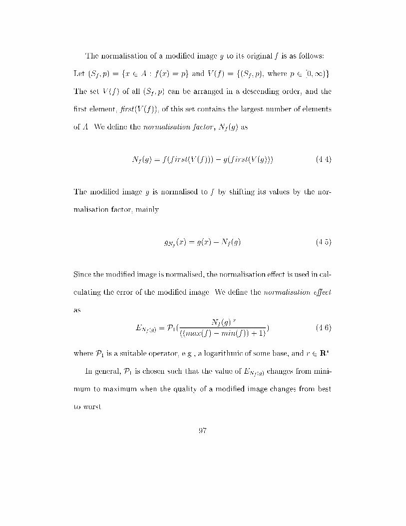
The normalisation of a modi�ed image g to its original f is as follows:
Let (Sf ; p) = fx 2 A : f(x) = pg and V (f) = f(Sf ; p), where p 2 [0;1)g.
The set V (f) of all (Sf ; p) can be arranged in a descending order, and the
�rst element, �rst(V (f)), of this set contains the largest number of elements
of A. We de�ne the normalisation factor , Nf (g) as
Nf (g) = f(first(V (f)))� g(first(V (g))) (4.4)
The modi�ed image g is normalised to f by shifting its values by the nor-
malisation factor, mainly
gNf(x) = g(x) +Nf (g) (4.5)
Since the modi�ed image is normalised, the normalisation e�ect is used in cal-
culating the error of the modi�ed image. We de�ne the normalisation e�ect
as
ENf (g) = P1(jNf(g)jr
((max(f)�min(f)) + 1)) (4.6)
where P1 is a suitable operator, e.g., a logarithmic of some base, and r 2 R�.
In general, P1 is chosen such that the value of ENf (g) changes from mini-
mum to maximum when the quality of a modi�ed image changes from best
to worst.
97
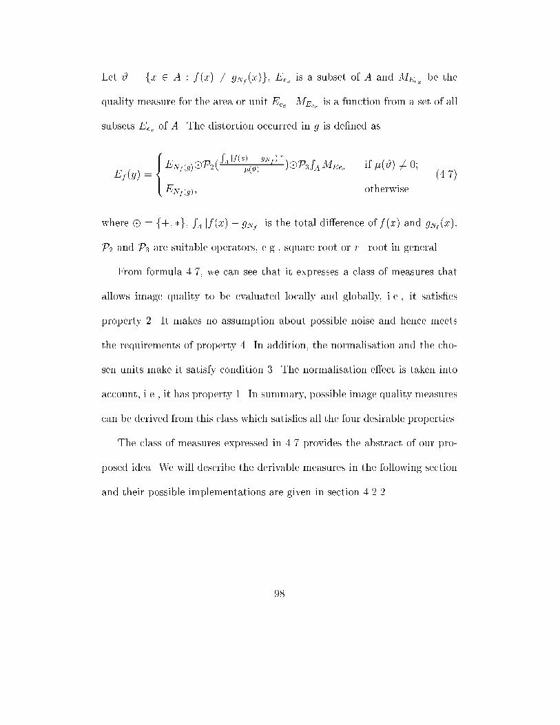
Let # = fx 2 A : f(x) 6= gNf(x)g, Eex is a subset of A and MEex
be the
quality measure for the area or unit Eex. MEexis a function from a set of all
subsets Eex of A. The distortion occurred in g is de�ned as
Ef (g) =
8>><>>:ENf (g)�P2(
RAjf(x) � gN
f)jr
�(#))�P3
RAMEex if �(#) 6= 0;
ENf (g); otherwise.
(4.7)
where � = f+; �g,RA jf(x)� gNf
j is the total di�erence of f (x ) and gNf(x ),
P2 and P3 are suitable operators, e.g., square root or r�root in general.
From formula 4.7, we can see that it expresses a class of measures that
allows image quality to be evaluated locally and globally, i.e., it satis�es
property 2. It makes no assumption about possible noise and hence meets
the requirements of property 4. In addition, the normalisation and the cho-
sen units make it satisfy condition 3. The normalisation e�ect is taken into
account, i.e., it has property 1. In summary, possible image quality measures
can be derived from this class which satis�es all the four desirable properties.
The class of measures expressed in 4.7 provides the abstract of our pro-
posed idea. We will describe the derivable measures in the following section
and their possible implementations are given in section 4.2.2.
98
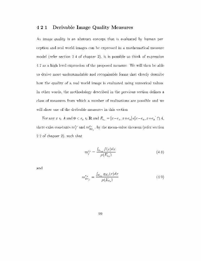
4.2.1 Derivable Image Quality Measures
As image quality is an abstract concept that is evaluated by human per-
ception and real world images can be expressed in a mathematical measure
model (refer section 2.4 of chapter 2), it is possible to think of expression
4.7 as a high level expression of the proposed measure. We will then be able
to derive more understandable and recognisable forms that closely describe
how the quality of a real world image is evaluated using numerical values.
In other words, the methodology described in the previous section de�nes a
class of measures from which a number of realisations are possible and we
will show one of the derivable measures in this section.
For any x 2 A and 0 < ex 2 R and Eex = [x�ex; x+ex]�[x�ex; x+ex]TA,
there exist constants mexf andmex
gNf
, by the mean-value theorem (refer section
2.2 of chapter 2), such that
mexf =
REex
f(x)dx
�(Eex)(4.8)
and
mexgN
f
=
REex
gNf(x)dx
�(Eex)(4.9)
99
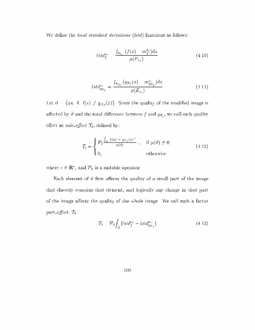
We de�ne the local standard deviations (lstd) functions as follows:
lstdexf =
REex
(f(x)�mexf )dx
�(Eex)(4.10)
lstdexgN
f
=
REex
(gNf(x)�m
exgN
f
)dx
�(Eex)(4.11)
Let # = fx2 A: f(x) 6= gNf(x)g. Since the quality of the modi�ed image is
a�ected by # and the total di�erence between f and gNf, we call such quality
e�ect as side e�ect T2, de�ned by:
T2 =
8><>:P2RAjf(x) � gN
f(x)jr
�(#), if �(#) 6= 0;
0; otherwise.
(4.12)
where r 2 R�, and P3 is a suitable operator.
Each element of # �rst a�ects the quality of a small part of the image
that directly contains that element, and logically any change in that part
of the image a�ects the quality of the whole image. We call such a factor
part e�ect , T3.
T3 = P3ZAjlstdexf � lstd
exgN
f
j (4.13)
100
The distortion error, called IQME (image Quality Measure), can then be
computed as the derivative of normalisation e�ect, part-e�ect and side-e�ect
IQME = T1 � T2 � T3 (4.14)
where T1 is ENf (g) as in (4.6).
We have shown a possible realisation of the proposed class of measures
described in section 4.2. The formula 4.14 is more understandable and recog-
nisable than the formula 4.7. We can see that the units employed in the
computation are rectangles, the choice of T2 and T3 are more meaningful
and recognisable. We will show one possible implementation in the following
section together with the experimental results and comparisons to the two
most commonly used methods. The implementation will further give a better
insight of the abstract idea expressed in formula 4.7.
4.2.2 A Possible Realisation of IQME
The proposed class of measures described in section 4.2 can be considered as
a framework from which several di�erent implementations can be made. For
di�erent image applications, how well the proposed method coincides with
human visual perception depends on the operators P1, P2, and P3. Since,
di�erent applications may tolerate di�erent kinds of noise di�erently, we in-
101
clude such operators for necessary modi�cations. In this section we describe
one of the possible implementations of the solution to the equation 4.14.
Let fxjig and fyjig represent the original and the modi�ed images in the
discrete form respectively. We will drop the subscripts i ; j when not neces-
sary. Also assume that fxjig and fyji g are grey-scale images whose domain is
A = [0; i� 1] � [0; j � 1] and range is of M levels (images can be represented
as functions as discussed in chapter 2). Given an odd number m 2 N and m
> 1, for every pixel p, select the greatest square of odd size l � l such that
l � m and p is the central pixel of that square. Since the size of the images
is n = i � j , there are n such squares, including the particular case that the
smallest square is of size 1 consisting of 1 pixel for the special case where the
pixel is on the boundary (in this case the value of l is 1). We use the square
units of size 3 in our implementation and experimentation, however l can be
any odd number that is less than i and j .
Let (Sfx
j
ig; p) = f(i; j) 2 A : fxjig = pg and V (fxjig) = f(Sfxj
ig; p)g, where
p 2 [0;M � 1]. The set V (fxjig) of all (Sfxjig; p) can be arranged in a de-
scending order, and the �rst element, �rst(V (fxjig)), of this set contains the
largest number of elements of A. The normalisation factor Nf (g) is
Nfx
j
ig(fyjig) = fxj1i1g � fy
j2i2g (4.15)
102
where fxj1i1g 2 �rst(V (fxjig)) and fy
j2i2g 2 �rst(V (fyji g)).
Let fzji g = fyji g + N
fxj
ig(fyji g). The modi�ed image fyji g is normalised to
fxjig, resulting in fzji g.
First, we give a speci�cation for T1, the normalisation e�ect as
T1 =W1 � (1:0
1:0� (sqrt(jfirst(V (fxjig))� first(V (fyji g))j=M))) (4.16)
where M= 256 is the grey-level, and W1 is some weight. The weight is
included here for greater exibly that di�erent applications may use to adjust
their tolerance to di�erent kinds of noise as mentioned in the previous section.
The side-e�ect and part-e�ect, T2 and T3, are in turn computed as follows:
Let mu(u;v)
fxg and mu(u;v)
fzg in turn be the mean values of fxg and fzg (the
modi�ed and original images) of the square u(u; v) at position (u,v). They
are de�ned as
m
u(u;v)
fxg =1
l � l
l�1
2Xs=� l�1
2
l�1
2Xt=� l�1
2
xv+tu+s (4.17)
m
u(u;v)
fzg =1
l � l
l�1
2Xs=� l�1
2
l�1
2Xt=� l�1
2
zv+tu+s (4.18)
From equations 4.10 and 4.11, we de�ne the local standard deviations as
follows:
lstdfxg(u; v) =1
l � l
l�1
2Xs=� l�1
2
l�1
2Xt=� l�1
2
(xv+tu+s �m
u(u;v)
fxg ) (4.19)
103
lstdfzg(u; v) =1
l � l
l�1
2Xs=� l�1
2
l�1
2Xt=� l�1
2
(zv+tu+s �m
u(u;v)
fzg ) (4.20)
Let Dfxg(u; v) =
8><>:lstdfxg(u; v), if lstdfxg(u; v) 6= 0;
ln(M)
ln(2); otherwise.
where lstdfxg(u; v) is de�ned by (4.19) and M is the grey levels of the image
as described previously.
We de�ne the local standard deviation di�erence lstd dif(u; v) (the total lo-
cal standard deviation di�erence tol lstd dif) and local absolute di�erence
a dif(u; v) (the total local absolute di�erence tol a dif) as follows:
lstd dif(u; v) =jlstdfxg(u; v)� lstdfzg(u; v)j
Dfxg(u; v)(4.21)
Let a u dif(u; v) = 1l�l
P l�1
2
s=� l�1
2
P l�1
2
t=� l�1
2
jxv+tu+s � zv+tu+sj.
We de�ne the local absolute di�erence
a dif(u; v) =
8>>>><>>>>:
a u dif(u; v) if lstd dif(u,v) = 0 & a u dif(u; v) 6= 0;
jxvu � zvuj if lstd dif(u,v) = 0 & a u dif(u; v) = 0;
0; otherwise.(4.22)
104
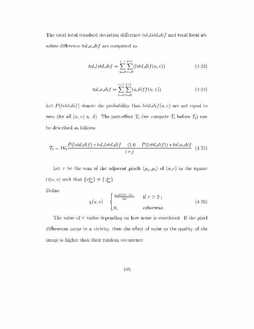
The total local standard deviation di�erence tol lstd dif and total local ab-
solute di�erence tol a dif are computed as
tol lstd dif =i�1Xu=0
j�1Xv=0
(lstd dif(u; v)) (4.23)
tol a dif =i�1Xu=0
j�1Xv=0
(a diff(u; v)) (4.24)
Let P (lstd dif) denote the probability that lstd dif(u; v) are not equal to
zero (for all (u; v) 2 A). The part-e�ect T3 (we compute T3 before T2) can
be described as follows:
T3 =W3
P (lstd dif) � tol lstd dif + (1:0� P (lstd dif)) � tol a dif
i � j (4.25)
Let � be the sum of the adjacent pixels (pu; pv) of (u,v) in the square
u(u; v) such that fxpvpug 6= fzpvpug.
De�ne
�(u; v) =
8><>:
a dif(u;v)��
l�lif � � 2 ;
0; otherwise.
(4.26)
The value of � varies depending on how noise is correlated. If the pixel
di�erences occur in a vicinity, then the e�ect of noise to the quality of the
image is higher than their random occurrence.
105
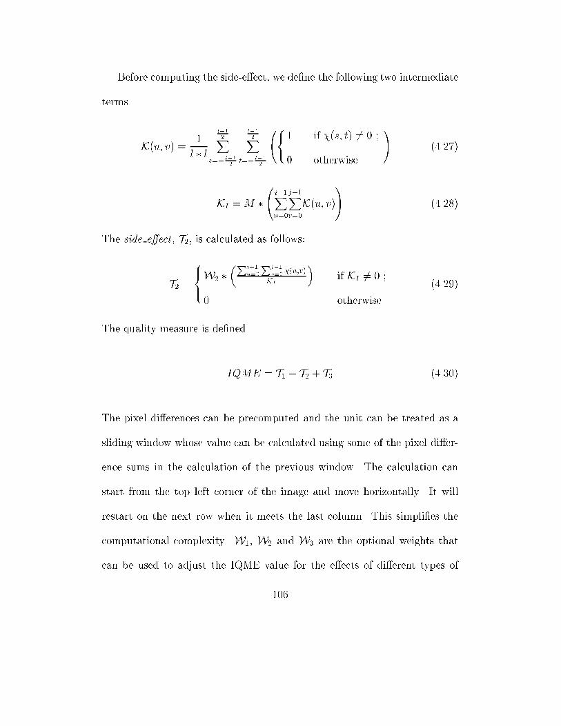
Before computing the side-e�ect, we de�ne the following two intermediate
terms.
K(u; v) = 1
l � l
l�1
2Xs=� l�1
2
l�1
2Xt=� l�1
2
0@8<:1 if �(s; t) 6= 0 ;
0 otherwise.
1A (4.27)
KI = M �0@ i�1Xu=0
j�1Xv=0
K(u; v)1A (4.28)
The side e�ect , T2, is calculated as follows:
T2 =
8><>:W2 �
�Pi�1
u=0
Pj�1
v=0�(u;v)
KI
�if KI 6= 0 ;
0 otherwise.
(4.29)
The quality measure is de�ned
IQME = T1 + T2 + T3 (4.30)
The pixel di�erences can be precomputed and the unit can be treated as a
sliding window whose value can be calculated using some of the pixel di�er-
ence sums in the calculation of the previous window. The calculation can
start from the top left corner of the image and move horizontally. It will
restart on the next row when it meets the last column. This simpli�es the
computational complexity. W1, W2 and W3 are the optional weights that
can be used to adjust the IQME value for the e�ects of di�erent types of
106
noise depending on the requirement of the application.
We have described one implementation in this section. Since it is very
di�cult to mathematically prove the correctness of an image quality mea-
sure, the validity of an image quality measure is con�rmed only when it is
experimented. We will describe our experiments on a number of tests and
show a set of selected results of important tests in the following section to
show the superiority of IQME.
4.3 Applicability of IQME
One of the most important part in the process of providing an image quality
measure is to set up proper test conditions and experimental data. No matter
which approach one follows, subjective or objective, the test conditions can
be di�erent between approaches, but the test input data should be the same.
Ideally, test input data should include all possible types of noise and their
combinations. Also the experiments should be carried out thoroughly for all
possible cases. In general, the test requirements are:
1. Test data should include all possible types of noise generated by known
lossy compression techniques.
107
2. Test data should include all other possible types of noise generated by
other image compression applications.
3. Tests must be conducted for all possibilities unless the measure is math-
ematically proved to be correct. For example, for lossy image compres-
sion tests should be carried out for all possible compression ratios.
Since conducting tests that meet the above requirements is very time con-
suming, the test is often carried out on certain selected test data using some
known image compression algorithms. We carried out di�erent tests on a
number of images, and the selected tests are:
1. In the �rst test, the original images are compressed by the JPEG coder,
the EPIC [SA97], and Davis' fractal-wavelet based coder [Dav96]. We
choose these image compression algorithms since they generate di�erent
types of noise in di�erent ways. The JPEG generates blockiness errors
while the EPIC generates ringing noise and Davis' coder generates noise
at the edges of the image. The test images are compressed at di�erent
compression ratios and the three quality measures, viz., MSE, colour-
based technique and our proposed IQME are used to measure the errors.
The four standard test images, Lena, Barbara, Goldhill and Mandrill
are included for in our �rst test for convenient comparison with other
methods. The selected results are listed in Tables 4.1-4.3.
108

2. In the second test, we generate a number of di�erent possible noise
by using the modi�ed versions of the three above-mentioned working
compression coders. The modi�ed coders are erroneous and hence can
generate unexpected results. The main idea of this test is to capture
a number of possible errors that can be generated by certain buggy
image compression programs. This will be a bene�t when an image
compression algorithm is implemented and tested. The results of this
test showed that the proposed method works well while the other two
methods either do not work at all or they are inconsistent. The selected
results are listed in Table 4.4.
3. In the third test, we generate possible noise that can either be caused
by image applications such as editing, enlargement, etc. Some noise is
also generated with the assumption that it is unknown noise which is
not generated by any existing image applications. Selected results are
listed in Table 4.5. The results from our test show that the other two
methods fail to capture noise such as the pixel values in one area of the
image is set to the same value that is much di�erent from the average
value of the area, noise generated by the combination of random and
structured noise, and noise generated by blurring or shifting one part
of the image. However, from the experiment on the generated noise
109
in this test, our method shows its strength to cope well with possible
unknown noise.
The selected modi�ed images used in the second and third tests are re-
produced in Figures 4.3-4.10. These images correspond to the popular Lena
and Mandrill images, and are generated by the insertion of unusual noise,
by Davis' algorithm [Dav96] (included for comparison only), and two se-
lected buggy programs which are the modi�ed versions of the EPIC coder
[SA97], and the fractal compression coder based on quadtree [Fis95], called
Unr1Comp and Unr2Comp. The selected modi�ed images are:
1. L1 : Lena's reconstructed image, compressed by Davis' algorithm with
compression ratio 8:1. This image is displayed for visual comparison
with L3.
2. L2 : Lena's reconstructed image, compressed by Unr1Comp algorithm.
The left side of the image is changed by the noise.
3. L3 : Lena's reconstructed images, compressed by Davis' algorithm with
compression ratio 64:1. This image is displayed for visual comparison
with L4.
4. L4 : Lena's modi�ed image with the insertion of noise. One-third of
pixels are shifted down by 20 and the rest are shifted up by 15. This
110
image looks very much the same as the original.
5. M1 : Mandrill's reconstructed image, compressed by Davis' algorithm
with compression ratio 64:1. This image is displayed for visual com-
parison with M4.
6. M2 : Mandrill's reconstructed image, compressed by Unr2Comp algo-
rithm. The left side of the image is changed by the noise.
7. M3 : Mandrill's reconstructed image, compressed by Davis' algorithm
with compression ratio 4:1. This image is displayed for visual compar-
ison with M3.
8. M4 : Mandrill's modi�ed image with the insertion of noise. The gen-
erated noise is based on the idea that sometimes an area of the image
is changed with the �lling of a certain type of noise. Namely, di�erent
pixel values in that area are replaced by a value.
We include peak-signal-to-noise ratio (PSNR), root-mean-square error
(RMSE), the colour-based di�erence (CDIF) which is based on colour his-
togram [ASB96], and IQME results in the tables for comparison. For PSNR,
the larger is the value of PSNR the better is the quality of the image, and
for the others, RMSE, CDIF and IQME, the smaller is the value, the better
is the quality (smaller error size implies better quality).
111
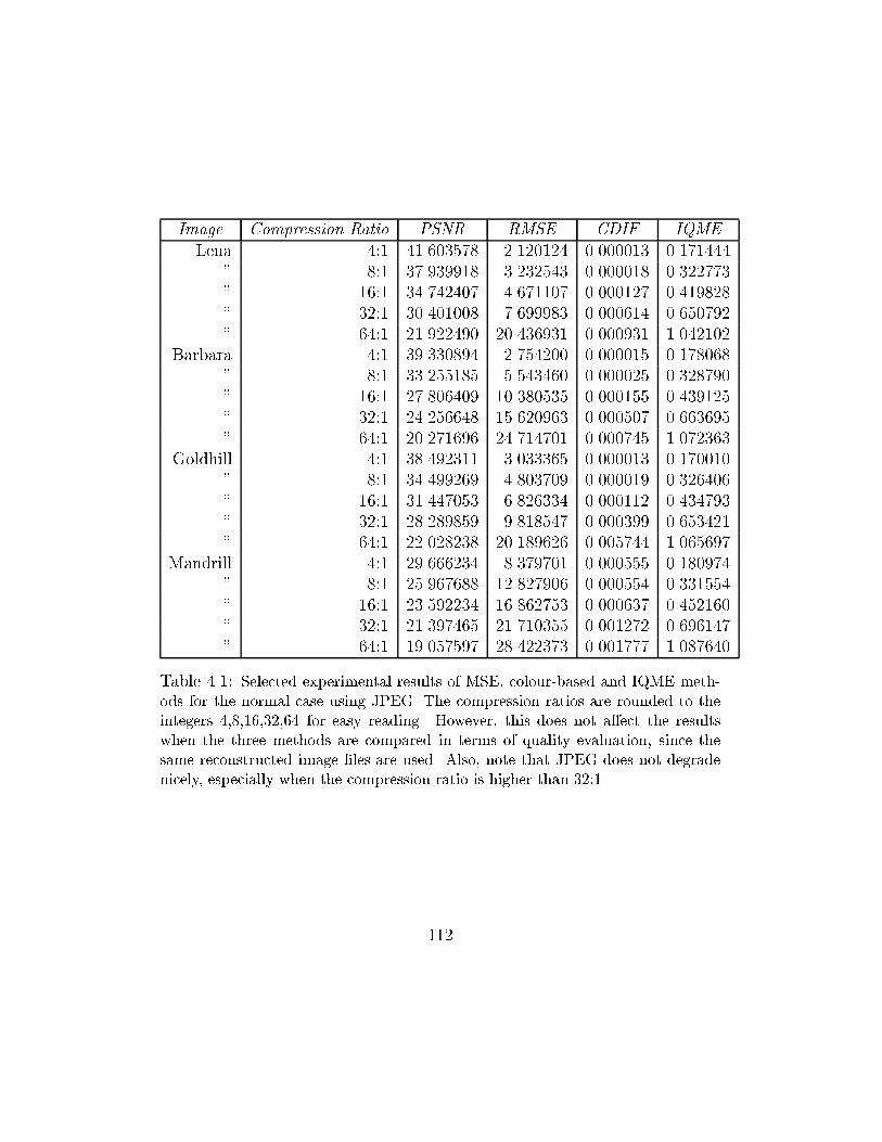
Image Compression Ratio PSNR RMSE CDIF IQME
Lena 4:1 41.603578 2.120124 0.000013 0.171444
" 8:1 37.939918 3.232543 0.000018 0.322773
" 16:1 34.742407 4.671107 0.000127 0.419828
" 32:1 30.401008 7.699983 0.000614 0.650792
" 64:1 21.922490 20.436931 0.000931 1.042102
Barbara 4:1 39.330894 2.754200 0.000015 0.178068
" 8:1 33.255185 5.543460 0.000025 0.328790
" 16:1 27.806409 10.380535 0.000155 0.439125
" 32:1 24.256648 15.620963 0.000507 0.663695
" 64:1 20.271696 24.714701 0.000745 1.072363
Goldhill 4:1 38.492311 3.033365 0.000013 0.170010
" 8:1 34.499269 4.803709 0.000019 0.326406
" 16:1 31.447053 6.826334 0.000112 0.434793
" 32:1 28.289859 9.818547 0.000399 0.653421
" 64:1 22.028238 20.189626 0.005744 1.065697
Mandrill 4:1 29.666234 8.379701 0.000555 0.180974
" 8:1 25.967688 12.827906 0.000554 0.331554
" 16:1 23.592234 16.862753 0.000637 0.452160
" 32:1 21.397465 21.710355 0.001272 0.696147
" 64:1 19.057597 28.422373 0.001777 1.087640
Table 4.1: Selected experimental results of MSE, colour-based and IQME meth-
ods for the normal case using JPEG. The compression ratios are rounded to the
integers 4,8,16,32,64 for easy reading. However, this does not a�ect the results
when the three methods are compared in terms of quality evaluation, since the
same reconstructed image �les are used. Also, note that JPEG does not degrade
nicely, especially when the compression ratio is higher than 32:1
112
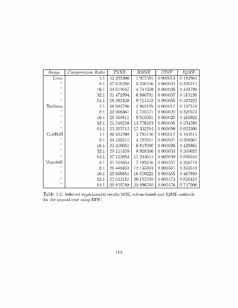
Image Compression Ratio PSNR RMSE CDIF IQME
Lena 4:1 42.208206 1.977561 0.000013 0.182864
" 8:1 37.956288 3.226456 0.000024 0.336214
" 16:1 34.611647 4.741959 0.000035 0.443796
" 32:1 31.471994 6.806761 0.000037 0.513199
" 64:1 28.382438 9.714452 0.000055 0.583222
Barbara 4:1 38.993786 2.863195 0.000017 0.197518
" 8:1 32.968361 5.729571 0.000022 0.320572
" 16:1 28.560811 9.516991 0.000025 0.415926
" 32:1 25.348238 13.776163 0.000035 0.534760
" 64:1 23.303713 17.432294 0.000050 0.622300
Goldhill 4:1 39.202700 2.795150 0.000017 0.184515
" 8:1 34.529515 4.787011 0.000021 0.308361
" 16:1 31.458051 6.817696 0.000026 0.428861
" 32:1 29.115370 8.928360 0.000033 0.565027
" 64:1 27.112653 11.243655 0.000049 0.686340
Mandrill 4:1 31.101654 7.103256 0.000557 0.206719
" 8:1 26.449433 12.135803 0.000561 0.345518
" 16:1 23.688851 16.676221 0.000565 0.487930
" 32:1 22.042157 20.157299 0.000573 0.620419
" 64:1 20.859780 23.096766 0.000576 0.747506
Table 4.2: Selected experimental results MSE, colour-based and IQME methods
for the normal case using EPIC
113
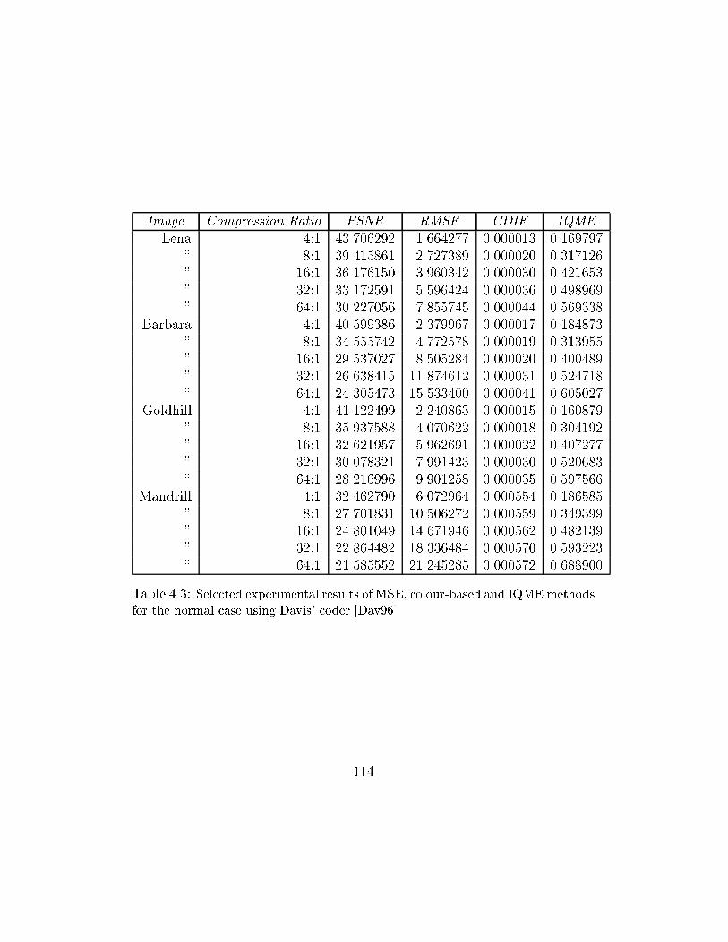
Image Compression Ratio PSNR RMSE CDIF IQME
Lena 4:1 43.706292 1.664277 0.000013 0.169797
" 8:1 39.415861 2.727389 0.000020 0.317126
" 16:1 36.176150 3.960342 0.000030 0.421653
" 32:1 33.172591 5.596424 0.000036 0.498969
" 64:1 30.227056 7.855745 0.000044 0.569338
Barbara 4:1 40.599386 2.379967 0.000017 0.184873
" 8:1 34.555742 4.772578 0.000019 0.313955
" 16:1 29.537027 8.505284 0.000020 0.400489
" 32:1 26.638415 11.874612 0.000031 0.524718
" 64:1 24.305473 15.533400 0.000041 0.605027
Goldhill 4:1 41.122499 2.240863 0.000015 0.160879
" 8:1 35.937588 4.070622 0.000018 0.304192
" 16:1 32.621957 5.962691 0.000022 0.407277
" 32:1 30.078321 7.991423 0.000030 0.520683
" 64:1 28.216996 9.901258 0.000035 0.597566
Mandrill 4:1 32.462790 6.072964 0.000554 0.186585
" 8:1 27.701831 10.506272 0.000559 0.349399
" 16:1 24.801049 14.671946 0.000562 0.482139
" 32:1 22.864482 18.336484 0.000570 0.593223
" 64:1 21.585552 21.245285 0.000572 0.688900
Table 4.3: Selected experimental results of MSE, colour-based and IQMEmethods
for the normal case using Davis' coder [Dav96]
114
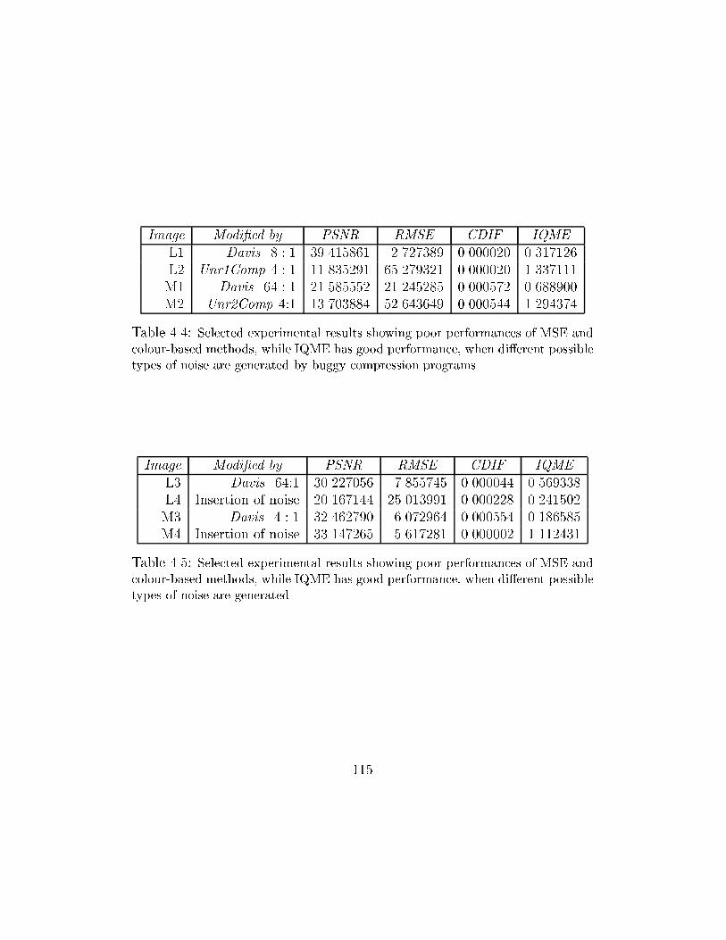
Image Modi�ed by PSNR RMSE CDIF IQME
L1 Davis 8 : 1 39.415861 2.727389 0.000020 0.317126
L2 Unr1Comp 4 : 1 11.835291 65.279321 0.000020 1.337111
M1 Davis 64 : 1 21.585552 21.245285 0.000572 0.688900
M2 Unr2Comp 4:1 13.703884 52.643649 0.000544 1.294374
Table 4.4: Selected experimental results showing poor performances of MSE and
colour-based methods, while IQME has good performance, when di�erent possible
types of noise are generated by buggy compression programs
Image Modi�ed by PSNR RMSE CDIF IQME
L3 Davis 64:1 30.227056 7.855745 0.000044 0.569338
L4 Insertion of noise 20.167144 25.013991 0.000228 0.241502
M3 Davis 4 : 1 32.462790 6.072964 0.000554 0.186585
M4 Insertion of noise 33.147265 5.617281 0.000002 1.112431
Table 4.5: Selected experimental results showing poor performances of MSE and
colour-based methods, while IQME has good performance, when di�erent possible
types of noise are generated
115
From the selected experimental results of the �rst test listed in Table 4.1,
we can see that the RMSE (PSNR), CDIF and IQME values change from
low to high when the compression ratios change from 4:1 to 64:1. This means
that the three measures are indicators that can satisfy the three properties
described in section 4.1. We can also see that there is a big change of RMSE
(or PSNR) values from image to image. The RMSE value of Lena's com-
pressed image at the compression ratio 4:1 is 2.120124 (PSNR = 41.603578)
while the RMSE value of Mandrill's compressed image of the same compres-
sion ratio is 8.379701 (PSNR = 29.666234). In addition, the RMSE value of
Lena's compressed image at the compression ratio 32:1 is 7.699983 (PSNR
= 30.401008) that is smaller than the RMSE value of Mandrill's compressed
image at compression ratio 4:1. This indicates that RMSE is not consistent.
There is a similar problem with the colour-based technique when we compare
the CDIF values of Lena and Mandrill's compressed images. From the same
table, we can see that the IQME values are more consistent. By observing
the results in Table 4.2 and 4.3, we can see the inconsistencies of RMSE and
CDIF, even they satisfy the three properties described in section 4.1, while
IQME demonstrates its consistency.
From the selected experimental results of the second test listed in Table
4.4, and from the visual inspection of the printed images one can observe
116
that the colour-based method does not work when images L1 and L2 are
compared (refer Figures 4.3 and 4.4), or M1 and M2 are compared (refer
Figures 4.5 and 4.6). Both the mean-square-error (RMSE and PSNR are
used in the experiments) and colour-based methods do not work when im-
ages L3 and L4 are compared (refer Figures 4.7 and 4.8). Also they do not
work when images M3 and M4 are compared (refer Figures 4.9 and 4.10).
When two images are compared in terms of quality, one desires a measure
D that parallels with the subjective evaluation (besides the three desirable
properties described in section 4.1). That is if the di�erences in quality
judged by human eyes is large, then the mathematical values of D should
also be large. MSE and its variants such as RMSE and PSNR do not parallel
with the subjective evaluation. For example, at the compression ratio 4:1, the
reconstructed images of Lena and Mandrill do not look di�erent from their
originals by human eyes, however the RMSE and PSNR values of Lena and
Mandrill's reconstructed images are quite di�erent (For Lena's reconstructed
image, compressed at ratio 4:1 by JPEG, the value of RMSE is 2.120124 , and
the value of PSNR is 41.603578, while for Mandrill's reconstructed image,
compressed at ratio 4:1 by JPEG, the value of RMSE is 8.379701 and the
value of PSNR is 29.666234). More results can be found from Tables 4.1-4.3
and Figures 4.11-4.14.
117
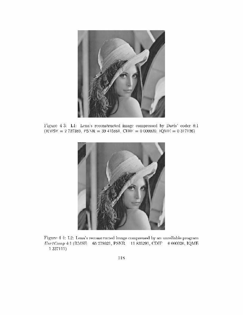
Figure 4.3: L1: Lena's reconstructed image compressed by Davis' coder 8:1
(RMSE = 2.727389, PSNR = 39.415861, CDIF = 0.000020, IQME = 0.317126)
Figure 4.4: L2: Lena's reconstructed image compressed by an unreliable program
Unr1Comp 4:1 (RMSE = 65.279321, PSNR = 11.835291, CDIF = 0.000020, IQME
= 1.337111)
118
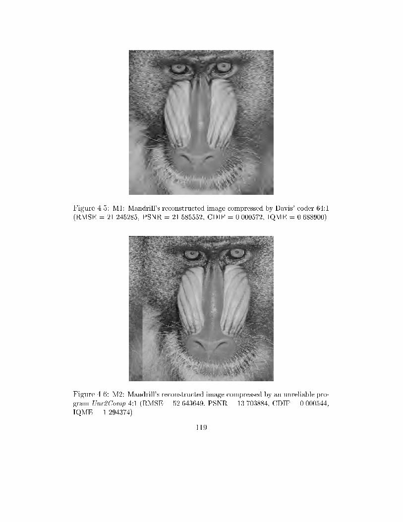
Figure 4.5: M1: Mandrill's reconstructed image compressed by Davis' coder 64:1
(RMSE = 21.245285, PSNR = 21.585552, CDIF = 0.000572, IQME = 0.688900)
Figure 4.6: M2: Mandrill's reconstructed image compressed by an unreliable pro-
gram Unr2Comp 4:1 (RMSE = 52.643649, PSNR = 13.703884, CDIF = 0.000544,
IQME = 1.294374)
119

Figure 4.7: L3: Lena's reconstructed image compressed by Davis' coder 64:1
(RMSE = 7.855745, PSNR = 30.227056, CDIF = 0.000044, IQME = 0.569338)
Figure 4.8: L4: Lena's modi�ed image with the insertion of noise. One-third of
pixels are shifted down by 20 and the rest are shifted up by 15 (RMSE = 25.013991,
PSNR = 20.167144, CDIF = 0.000228, IQME = 0.241502)
120
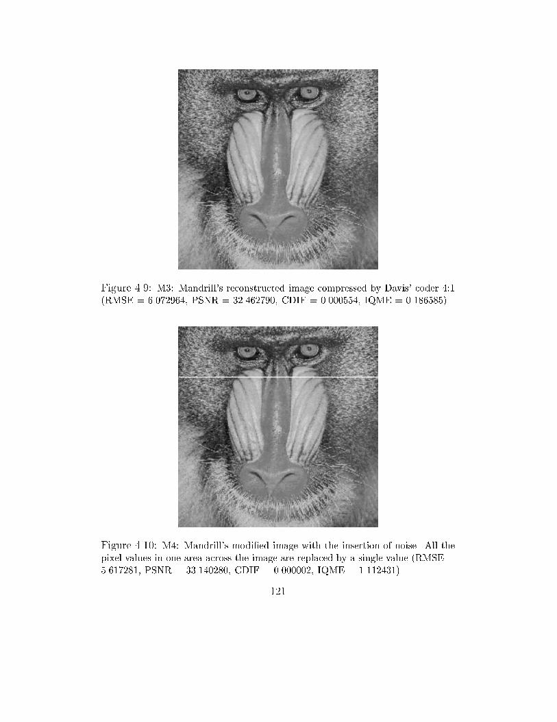
Figure 4.9: M3: Mandrill's reconstructed image compressed by Davis' coder 4:1
(RMSE = 6.072964, PSNR = 32.462790, CDIF = 0.000554, IQME = 0.186585)
Figure 4.10: M4: Mandrill's modi�ed image with the insertion of noise. All the
pixel values in one area across the image are replaced by a single value (RMSE =
5.617281, PSNR = 33.140280, CDIF = 0.000002, IQME = 1.112431)
121
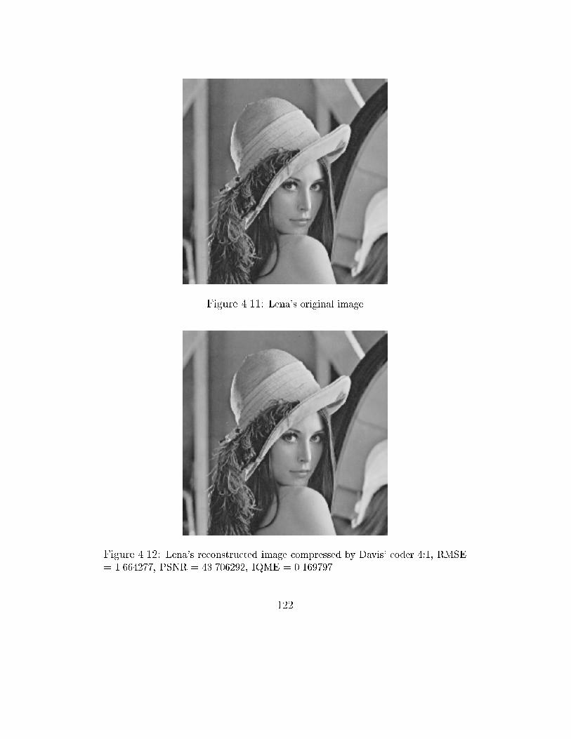
Figure 4.11: Lena's original image
Figure 4.12: Lena's reconstructed image compressed by Davis' coder 4:1, RMSE
= 1.664277, PSNR = 43.706292, IQME = 0.169797
122
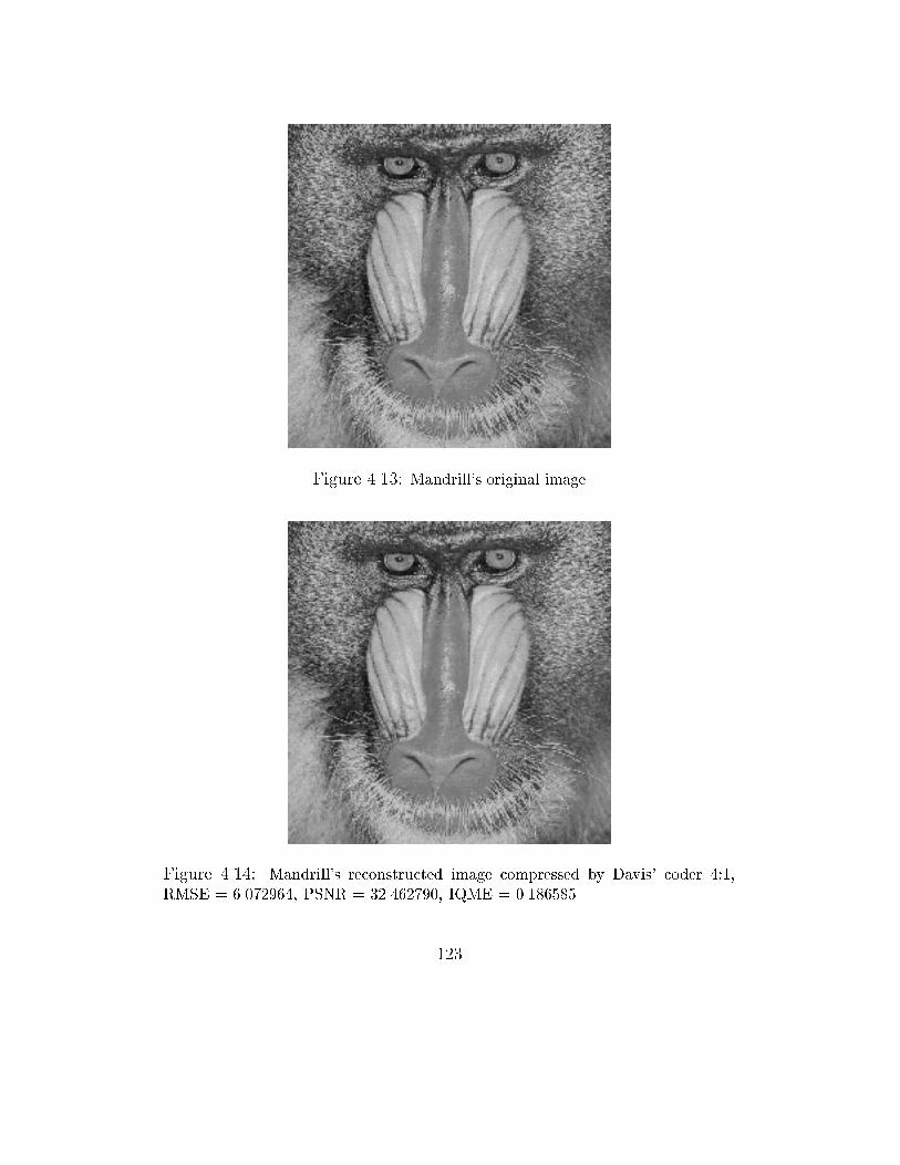
Figure 4.13: Mandrill's original image
Figure 4.14: Mandrill's reconstructed image compressed by Davis' coder 4:1,
RMSE = 6.072964, PSNR = 32.462790, IQME = 0.186585
123
The colour-based technique is claimed to be more accurate than the MSE
method. However, it also su�ers similar problems to the MSE method, as
shown by our experimental results. Our experiments showed that RMSE and
colour-based methods do not always satisfy the above-mentioned property,
while the proposed method exhibits that property. From the results listed
in Tables 4.1-4.3 and the Figures 4.11-4.14, one can see that the RMSE and
PSNR do not satisfy the desired property. At the compression ratio of 4
to 1, visually, the quality of the reconstructed images of Mandrill and Lena
are of the same level in comparison to their original images (Figures 4.11-
4.14). However, the RMSE and PSNR values of these reconstructed images
are very di�erent (refer Table 4.1). In comparison to MSE and its variants,
and the colour-based techniques, our experiment results shows that IQME
values parallel with the subjective evaluation. At the compression ratio of 4
to 1, the IQME values do not vary much for di�erent images.
In addition, with RMSE or PSNR, one may not be able to specify the
quality level of an image based on numerical values, since the RMSE numeri-
cal values do not parallel with human visual perception very well and depend
on the characteristics of the image. For instance, for the same level of quality,
RMSE values (or PSNR values) are often high (low) for complicated images
such as the image of Mandrill, and for more smooth images these numerical
124
values are often low (high) as in the case of Lena's image. The results from
Tables 4.1-4.3 show how RMSE (or PSNR) values vary from image to image.
The graphs (Figures 4.15-4.20) show how IQME and RMSE vary from image
to image with JPEG, EPIC and Davis image compression algorithms. From
Figures 4.15 and 4.16 we can observe that MSE does not behave consistently
while IQME shows its consistency. This is because MSE does not capture
blocking artifacts (generated by JPEG) well, while IQME performs very well.
One can easily see that for the same compression ratios, MSE varies so much
from image to image and from one compression technique to another. The
IQME also varies from image to image and from one compression technique
to another. However, its change is more consistent and parallels with the vi-
sual perception much better than MSE, especially at low compression ratios.
In summary, the results from the three tests show that MSE does not
correlate well with human perception for di�erent types of noise such as
blockiness, contrast, and structured noise. In addition, it fails to indicate
correctly the level of distortion in relation to the compression ratios, its val-
ues, and the visual assessments. The colour-based technique does not capture
possible noise generated by buggy programs and varies much from image to
image. The IQME works more consistently and shows its ability to capture
di�erent possible noise.
125
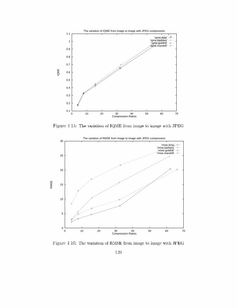
0.1
0.2
0.3
0.4
0.5
0.6
0.7
0.8
0.9
1
1.1
0 10 20 30 40 50 60 70
IQM
E
Compression Ratios
The variation of IQME from image to image with JPEG compression
’iqme.lena’’iqme.barbara’’iqme.goldhill’
’iqme.mandrill’
Figure 4.15: The variation of IQME from image to image with JPEG
0
5
10
15
20
25
30
0 10 20 30 40 50 60 70
RM
SE
Compression Ratios
The variation of RMSE from image to image with JPEG compression
’rmse.lena’’rmse.barbara’’rmse.goldhill’
’rmse.mandrill’
Figure 4.16: The variation of RMSE from image to image with JPEG
126
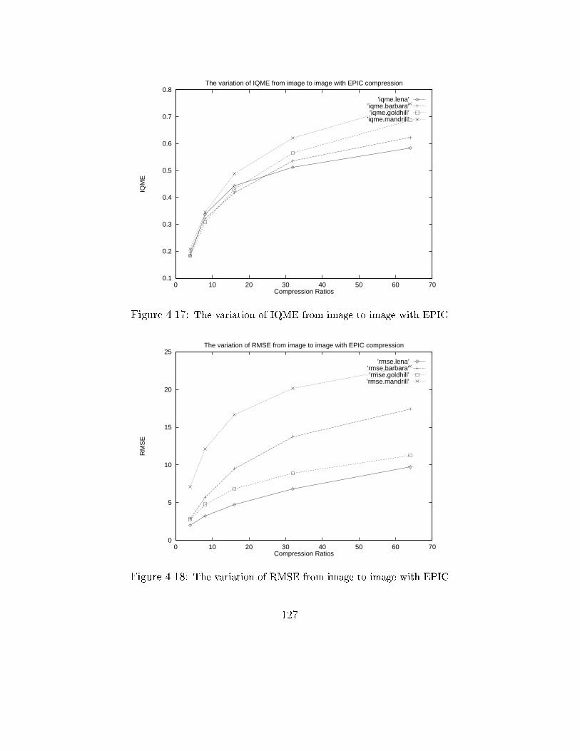
0.1
0.2
0.3
0.4
0.5
0.6
0.7
0.8
0 10 20 30 40 50 60 70
IQM
E
Compression Ratios
The variation of IQME from image to image with EPIC compression
’iqme.lena’’iqme.barbara’’iqme.goldhill’
’iqme.mandrill’
Figure 4.17: The variation of IQME from image to image with EPIC
0
5
10
15
20
25
0 10 20 30 40 50 60 70
RM
SE
Compression Ratios
The variation of RMSE from image to image with EPIC compression
’rmse.lena’’rmse.barbara’’rmse.goldhill’
’rmse.mandrill’
Figure 4.18: The variation of RMSE from image to image with EPIC
127

0.1
0.2
0.3
0.4
0.5
0.6
0.7
0 10 20 30 40 50 60 70
IQM
E
Compression Ratios
The variation of IQME from image to image with Davis’ compression
’iqme.lena’’iqme.barbara’’iqme.goldhill’
’iqme.mandrill’
Figure 4.19: The variation of IQME from image to image with Davis' algorithm
0
2
4
6
8
10
12
14
16
18
20
22
0 10 20 30 40 50 60 70
RM
SE
Compression Ratios
The variation of RMSE from image to image with Davis’ compression
’rmse.lena’’rmse.barbara’’rmse.goldhill’
’rmse.mandrill’
Figure 4.20: The variation of RMSE from image to image with Davis' algorithm
128
4.4 Conclusion
The need for a reliable image quality measure for evaluating the quality of
reconstructed images was recognised by image compression researchers. A
variety of image quality measures have been developed over the past two
decades. These include MSE and its variations, the PSNR incorporated
with HVS properties [OMM96], the linear predictors which use correlation
with subjective tests [Dal92, XH94], and methods incorporated with HVS
[WLB95, KGMA95]. The recent development of digital video technology
and the increasing number of multimedia applications such as digital libraries
have made the demand for an accurate quality measure more important and
urgent.
The subjective assessments based on human viewers are expensive, very
time consuming and require specialised laboratory conditions. Also the re-
sults depend very much on the test conditions and can be heavily biased
by the test person. This makes it di�cult for the subjective image quality
measures to become widely used methods. The study of HVS has lead to cer-
tain level of understanding that is useful for developing better image quality
methods. Multiple channel HVS models have been recently used in devising
measures to assess the quality of images [WLB95].
129
Other techniques such as colour-based measure, picture quality scale were
also proposed. Each of these methods has some advantages and disadvan-
tages, and no measure has demonstrated to work accurately and consistently
over a wide variety of input parameters [OMM96], therefore MSE and its
variant PSNR are still commonly used.
In this chapter, we have proposed a new class of image quality measures.
The main idea is to consider how human eyes are sensitive to noise spatially,
and why pixelwise methods such as MSE and the distortion class in (4.3) fail
to capture correlated noise. Our investigation shows that spatially human
eyes are more sensitive to errors that are concentrated in a small area than
distributed randomly in a larger area. In addition, the change of each pixel
value to the local area which contains that pixel can a�ect the quality of the
image locally and the e�ect of that area to the whole image, globally a�ects
the quality of the entire image. Furthermore, it is more accurate to compare
two images, the modi�ed and the original images, which are normalised to
a standard point. We reason that the modi�ed image should be normalised
with respect to its original and the normalisation factor should be used in
calculating the quality of the modi�ed image. The normalisation together
with the chosen units, which are larger than the individual pixels, allow to
eliminate the distance dependency condition, or viewing condition. The pro-
130

posed methodology makes no assumption about possible noise. Hence there
is a high probability that it can capture new noise generated from future im-
age coders and applications. The class is objective and hence can be useful
in �ne-tuning image coding. The validity of the proposed class of measures
will be further con�rmed in chapter 5 where it is employed to improve image
coding.
131
Chapter 5
Compression Enhancement
with Image Quality Measure
5.1 Introduction
The high demand for reducing storage and transmission time for still and
moving images has made the image compression research a very active area.
Early image compression techniques focus on the improvement of quanti-
sation. This has lead to a number of image compression algorithms based
mainly on enhanced quantisation techniques such as vector quantisation,
lattice quantisation [HW85, HG88, NK88, CLG89, JG89]. While image
compression using quantisation still continues to evolve and new quantisa-
132
tion strategies are proposed to provide more e�cient compression techniques
such as image compression using zero-tree [Sha93], image compression with
space-frequency quantisation [XRO93, XRO94]. There are many other com-
pression techniques that are based on the new ways of representing natu-
ral images such as image coding based on the Discrete Cosine Transform
(DCT) [Wal91], subband image coding [WO86, AFMN93], image compres-
sion through wavelet transform [DJL92, ABMD92, CAS+92], and image com-
pression based on fractal theory [BJ88, Jac90].
In general, most attempts in image compression focus on �nding a new
way to better represent images so that higher compression can be obtained.
Consequently, on the one hand those attempts have resulted in the discovery
of wavelet and this transform has made image compression more promising
for higher compression. The advantage of wavelet transform over DCT is that
with the same level of quality fewer wavelet transform coe�cients are required
to represent the signal than using Discrete Cosine Transform [DJL92, Sha93].
Recent discovery of wavelet packets [CMQW92] that can represent non-
stationary characteristics of signals better than wavelets has lead to a new
hope for very high image compression [CMQW92, XRO94, Uhl95]. On
the other hand, the successful application of Iterative Function System to
compress natural images has also lead to an interesting image compression
133
paradigm. The results from fractal coders have shown that for images which
possess high level of self-similarity, high compression can be obtained [Fis95].
While the study of new theories for representing images can lead to bet-
ter image compression, research in this area has also tried to understand
the human visual system (HVS) with the hope that they can use the knowl-
edge about HVS to better model images and hence better compression may
be achieved. For example, the use of a visual model with weighted Cosine
transform for image compression was proposed by Nill [Nil85], and a complete
image coding algorithm based on human visual perception was described by
Jayant [JJS93]. There have been a number of ways to improve image coding
such as devising better ways for quantisation [Sha93, XRO94], using hybrid
techniques to code images [Sim95, Dav96]. However the use of an image
quality measure in improving image coding has not been fully investigated
[LAE95, KGMA95]. This is because �nding a new distortion measure that
coincides with human perception better than the existing ones is not a sim-
ple task. Also, the new measure has to be objective and can easily be used
to improve image coding. This probably has made image compression re-
searchers focus more on �nding new mathematical representations of images
than �nding better distortion measures for improving image coding.
134
The main goal of this chapter is to show that image quality evaluation
is one of the important factors that should be taken into consideration in
improving image coding. We believe that good image quality evaluation
methods (or distortion measures) not only can be used to improve quanti-
sation but also allow to make better decision in selecting basis functions to
represent images. If this is true then better compression gain can be ob-
tained when a better distortion measure is employed in quantisation or in a
best basis selection algorithm of an image coder. We �rst discuss the two
main approaches in image coding area and concludes that lossy compression
performance depends on quantisation and the algorithm that is used to se-
lect best basis functions or the set of functions that represent images. We
will then mathematically show that the application of a distortion measure
D1 that coincides with human visual perception better than the distortion
D2 in the quantisation or best basis selection algorithm employed by a lossy
compression technique, can result in better compression. To experimentally
prove this we designed algorithms for image compression based on image
quality measure and constructed two coders in which our image quality mea-
sure IQME, proposed in chapter 4, and MSE are in turn used, to test our
hypothesis. In the �rst coder, called IQIC1, our proposed image quality eval-
uation method IQME, described in chapter 4, and the RMSE methods are
135
in turn used in the quantisation of the coding. In the second coder, called
IQIC2, IQME and RMSE are in turn used in the best wavelet packet basis
selection algorithm. The two coders are constructed to allow the employ-
ment of IQME and RMSE respectively in two cases, the quantisation and
best basis selection. The experimental results when IQME and RMSE are
separately used are compared, and the results from both coders when IQME
is employed are also compared with the results from other coders that are
recently reported in the literature. The conclusion shows that the appli-
cation of a good distortion measure in coding images can result in better
compression.
5.2 Image Compression and the Inverse Prob-
lem
Data compression has become an important issue in relation to storage and
transmission of information. Especially digital image compression is impor-
tant due to the high storage and transmission requirements.
The ultimate goal of image compression is to minimise the size of digi-
tised images while still retain high level of quality. In general, there are two
main approaches to image compression. Given an image, research in image
136
compression tries to �nd a set of maps that requires as minimum bits for
storage as possible and that set of maps can best represent the given image.
That is the set of maps can either map the given image to itself or be the best
approximate of the given image. Formally it can be described as follows:
Let f be the given image. In the �rst approach, one can �nd a set of
maps F = ff1; f2; :::fng such that
F(f) = f & Fon(g) � f ; n 2 N & 8g 2 (H (X); dh) (5.1)
where where Fon(g) means F is applied to g n times; (H (X),dh) denotes, the
Hausdor� space, the space of all real world images and dh is some suitable
metric.
This equation states that F maps f onto itself, and f is the �xed point
of F, i.e., can be approximately reconstructed from F, according to the �xed
point theorem described in 2.5 of chapter 2.
In the second approach, a set of basis functions F = ff1; f2; :::fng that
can approximate f is searched such that
f =nXi=1
fn + �; n 2 N & �! 0 (5.2)
That is F can approximately represent f . This equation shows that f can be
approximated by a set of functions, e.g., wavelets.
137
The problem of �nding a set of functions that can represent a given image
as expressed in equations 5.1 and 5.2 can be named as the inverse problem.
If � is the number of bits required to store F, then � is expected to be as
small as possible.
In looking for such a set of mappings F, research in fractal image com-
pression has shown that given an image, it is possible to �nd a �nite set of
functions, the Iterative Function Systems (IFS), that can map the image to
itself within a given degree of accuracy [BJ88, BH93, Fis95]. The collage
theorem [BH93] and its extension [Fis95] provide the �rst stepping stone
towards solving the inverse problem. The theorem states that a tiling of
an image out of smaller self-replicas can yield a good representation of the
image. However practical results from existing solutions do not achieve high
compression without a price. Fractal image coding is basically still block-
oriented coding with the involvement of matching search. Recent reports
[Sau95, BE95] have shown certain amount of enhancements in speed, how-
ever, in order to achieve high compression with good quality, fractal encoding
process still has to follow a time-consuming matching search in comparison
to other compression methods.
While researchers in the area of fractal image compression attempt to
solve the inverse problem fundamentally by looking for algorithms that can
138
�nd, from the parameter space of IFSs, a proper set of maps that map the
given image to itself, from the other direction researchers have been looking
for function(s) that can optimally approximate any image. The later direc-
tion has been active for a number of years and early solutions to the inverse
problem was the Fourier and Cosine transforms. The success of JPEG com-
pression which is based on DCT is an example. Recently, the discovery of
wavelets has made this research direction more active.
Most existing lossy image compression methods use either of the two
above mentioned approaches and possibly they employ a quantisation strat-
egy in the coding process. However, the performance of the quantisation
and the basis function selection algorithm, in general, depends on the distor-
tion measure in use. Consequently the compression gain from image coding
depends on the distortion measure. For example, transform coding such as
DCT and wavelet based coding heavily depends on the quantisation. Ex-
isting wavelet packet based coders use a best basis selection algorithm that
employs a distortion measure in the selection process [CMQW92, RV93]. The
coding gain depends on how well the best wavelet packet bases are selected
and this depends on the distortion measure in use.
In summary, most lossy image coders either employs quantisation strategy
or a best basis selection algorithm. The performance of those coders depends
139
either on the quantisation or the best basis selection algorithm, however the
performance of the quantisation and best basis selection algorithm depends
on the distortion that is being used. We believe that the employment of
a better distortion measure can result in better gain in image coding and
this has motivated us to consider the application of our proposed distortion
measure (IQME) described in chapter 4, to improve the quantisation process
and to make decisions in the selection of best wavelet packet bases.
5.3 The Hypothesis and Its Analysis
In this section we show that the use of a better distortion measure in selecting
representations to images and in improving quantisation will result in better
gain in image compression.
Let f be the original image, B be the library of wavelet packet bases, R
be the �xed bitrate, E1 and E2 be the distortion measures and assume that
E1 coincides with human visual perception better than E2 . b1 and b2 are
in turn the best bases selected by AE1B and AE2
B , the best basis algorithms
whose distortion measures are E1 and E2 respectively.
Since the given budget is the �xed bitrate R, the maximum cost to repre-
sent f by b1 or by b2 cannot exceed R. With this condition, we can assume
140
that the two representation costs are the same. That is
R(b1; f) = R(b1; f) (5.3)
where R(b1; f) and R(b2; f) are in turn the bit allocation costs to represent
f using b1 , b2 .
Since E1 coincides with human visual perception better than E2 , we have
Qf (b1 (f )) > Qf (b2 (f )) (5.4)
where b1 (f ) and b2 (f ) are the reconstructed images of f from the coded b1
and b2 , and Qf (:) is the quality function de�ned in chapter 4.
Now if [Qf (b1 (f ))� Qf (b2 (f ))] ! 0. That is if we can reduce the quality
of the reconstructed image b1 (f ), then the bit allocation cost for b1 will be
reduced, or it is not greater than the bit allocation cost for b2 . That is
R(b1; f) � R(b2; f) (5.5)
This equation indicates that if the two reconstructed images of f have the
same quality, then the number of bits used to represent the encoded image
using the best basis b1 is not greater than the cost required by using b2 .
Consequently, it is possible to obtain higher compression using E1 .
141
Similarly, we can prove that possibly higher compression can be obtained
if E2 is replaced by E1 in the quantisation process.
The above analysis described in this section shows that there is a pos-
sibility that better compression gain can be achieved if a better distortion
measure is used in the quantisation or best basis selection algorithm of a
coder. In the following section we employ IQME in the quantisation of im-
age coding to experimentally show that if IQME is used instead of MSE then
less error will be produced in the quantisation process. Then we describe
the coding algorithms of our coders IQIC1 and IQIC2 in sections 5.4.2 and
5.5.3 respectively. The former coder is designed to improve the quantisation
process, while the later one is designed to improve the selection of wavelet
packet best bases. The experimental results from our coders are shown in
sections 5.4.3 and 5.5.4 respectively.
5.4 Quantisation Improvement with IQME
One of the key elements of a lossy image coder is the quantisation. An image
coder with e�cient quantisation can provide high compression since the e�-
cient quantisation can reduce the errors occurred in the quantisation stage of
the coding process. During the quantisation process a distortion measure is
employed. A distortion measure that coincides well with human visual per-
142
ception can be used to reduce errors resulted from the quantisation. That
is the success of the quantisation process depends on the distortion in use.
The important role of image quality evaluation in improving quantisation is
experimentally shown in this section.
Let IQIC1IQME and IQIC1MSE represent the coder, that will be described
in the following sections, when IQME and MSE are used in the quantisation
process respectively. We �rst discuss the fractal wavelet-based compression
method on which IQIC1 is based. We will then describe the coding algo-
rithm and compare the results produced by IQIC1IQME and IQIC1MSE . We
demonstrate the bene�t of using a good image quality evaluation method
in improving quantisation by comparing the results of IQIC1IQME and the
results from the recently reported fractal wavelet-based compression method
[Dav96].
5.4.1 Fractal-Wavelet Based Image Coding
Fractal compression is motivated by the observation that important image
features, including straight edges and constant regions, are invariant under
rescaling. Fractal image compression takes advantage of this local scale in-
variance by using coarse scale image features to quantise �ne scale features.
Fractal image block-based coders perform a vector quantisation of image
143
blocks 1.
Fractal block image coding, as discussed in chapter 3, basically partitions
an image into a number of non-overlapping range blocks and approximates
each range with a domain block from a pool of domain blocks (from which
the codebook is constructed). This approximation entails the construction
of a contraction mapping from the image to itself (from the domain blocks
to the range blocks) of which the image is an approximate �xed point. The
parameters of the contraction mapping are stored as the compressed image
and the reconstructed image is formed by iteratively applying the mapping
on an arbitrary image.
In this section we propose an image coding scheme based on the fractal
block-based coding method, however it is more e�ective by the multiresolu-
tion decomposition in the wavelet domain and has the following properties:
1. The similarity among blocks of di�erent subbands in a multiresolution
decomposition of the image is exploited.
1The analog between fractal image compression and vector quantisation has already
been stressed by Jacquin in his �st publication [Jac90], and further discussed by [HMS96].
In the encoding, both methods use a set of vectors known as codebook blocks to approxi-
mate the blocks of the original image. In VQ, the codebook blocks are typically generated
from a set of training images. These blocks are needed by the decoder in order to recon-
struct an approximation of the original image. In fractal image compression, the codebook
is obtained from the original image. it is constructed from locally averaged and subsam-
pled isometries of larger blocks from the image. This codebook is neither present nor
needed at the decoder. The encoder �nds a contractive image operator whose �xed point
is an approximation of the original image. The �xed point is produced in the decoding by
iteratively applying the contractive operator on an arbitrary image.
144

2. Di�erent distortion measures can be employed to directly evaluate the
errors between the original and reconstructed image at the coding time.
3. Reduce the complexity of the range-domain block matching search.
4. Eliminate the blockiness artifacts that fractal block-based coders have.
In this coding scheme, the given image is �rst decomposed into a set of sub-
bands using the pyramid subband decomposition. The decomposition results
in a set of subbands that are localised in scale, orientation and space. The
range blocks of di�erent dimensions in each of the subbands corresponding
to the same scale and orientation are then chosen. The domain blocks are
chosen from the subimage at the next lower resolution. The maps from
a domain block to a range block are chosen such that the distortion error
is minimised (using IQME and MSE respectively for each case correspond-
ing to IQIC1IQME and IQIC1MSE). In the range-domain block matching,
rather than recursively coding range blocks from other blocks in the image,
as in standard fractal coders, this scheme approximates the range blocks of
a subimage from the blocks of the subimage at the next lower resolution.
This considerably simpli�es the decoding procedure, since no iteration of
the the contractive operator is necessary (in fractal coding scheme, the �xed
point or the reconstructed image is produced in the decoding by iteratively
applying the contractive operator on an arbitrary image). This also allows
145
more accurate control of the error between the original and the reconstructed
image. The decomposition automatically classi�es blocks, blocks in di�er-
ent subimages corresponding to the same orientation have similar spectral
contents, and hence this results in the reduction of the range-domain block
matching search time. More importantly, it allows to minimise error in the
block matching procedure with an accurate distortion measure. Lastly, due
to the nature of the coding procedure that operates in the subband domain,
the blocking e�ect is not visible in the reconstructed image.
In the following section, we describe the coding of IQIC1. We �rst de-
scribe the pyramid subband decomposition scheme adopted as the �rst stage
in IQIC1. We then describe the range domain block mappings where the
quantisation occurs and the employed distortion plays an important part.
5.4.2 IQIC1 Coding Algorithm
The goal of the proposed compression scheme is to approximate range blocks
by domain blocks with the support of a perceptual image distortion measure
to minimise the error resulted by the approximation (or quantisation said
in another word). The compression algorithm can be described in two main
parts, the signal decomposition and coding, as follows:
146
1. Signal (image) decomposition: We apply the subband decomposition
that was presented in [WO86, WBBW88] to the signal to be coded.
The decomposition is obtained by using two-channel �lters to �lter
the input signal with the lowpass �lter and then subsampling by a
factor of two. Let x (n) be the input signal, the pair �lters H0 and
G0 represent the analysis �lter bank, and the pair �lters H1 and G1
represent the synthesis �lter bank as shown in Figure 2.2 of chapter
2. The subband signal xL(n) is obtained by �ltering x (n) with the
lowpass �lter H0 and then subsampling by a factor of two. Similarly,
the other subband signal xH (n) is obtained by �ltering x (n) with the
highpass �lter G0 and then subsampling. We extend this procedure
to two-dimensional signals by decomposing the input image x (n) into
four subimages xLH (n), xHL(n), xLL(n), xHH (n). This procedure can
be iterated to obtain a multi-level decomposition of the image in the
pyramid form [Mal89]. At each decomposition level i , the subimage
xLLi (n) is decomposed into four subimages, xLHi+1 (n), xHLi+1 (n), x
LLi+1 (n),
xHHi+1 (n), for i = 1,...,M. The result of this decomposition is a set of
subimages which are localised in scale, orientation and space [Mal89].
2. Coding: The coding part is divided into two steps, the matched coding
and unmatched coding. In the �rst step (matched coding step), for a
147
given range block BR we search for a domain block BD from a subimage
of lower resolution recursively. If the search is not successful at this
stage, the actual coding of the given range block is deferred to the next
step (unmatched coding step).
(a) Matched coding: For each range block, e.g., BRi;j (block j at de-
composition level i of the subimage xLHi (n)), the search for a
domain block of the same dimension is conducted in the subimage
xLHi+1 (n). Let B Ri;j denote the approximation of the range block
BRi;j , we �nd the domain block BD
i+1 ;j1 and the optimal transform
(the optimal transform consists of the averaging and subsampling,
isometries transformation, and the contrast scaling. Refer section
2.5 of chapter 3) such that the visual distortion error resulted
from the di�erence between the range block and its approximate
is minimised. That is we �nd the domain block BDi+1 ;j1 , such that
Dm(BRi;j ;B
Ri ;j ) is minimum with respect to all possible choices of
the isometries and contrast scaling. Where Dm is the distortion
measure in use (IQME for the ICIQ1IQME case and MSE for the
ICIQ1MSE case), and Dm(BRi;j ;B
Ri;j ) is the computed error. The
subimages at the lowest resolution are coded independently using
the popular PCM [MR91].
148
(b) Unmatched coding: In the case there is no match for a given
range block, we code the coe�cients of this block using a predictive
vector quantiser described by Modestino and Kim [MK92], and the
quantiser output levels are entropy-coded using the Hu�man code
[Vit87]. This is because, the results from wavelet coding has shown
that it is possible to obtain good quality reconstructed images
while using less bit per coe�cient on average [WO86, ABMD92,
Sha93].
Despite its expansion in terms of wavelets, the algorithm presented above
is still equivalent to the usual fractal block transform. However, our coding
scheme has eliminated the blockiness artifacts that occur in fractal block
based coders. That is because our scheme operates in wavelet space 2. The
second advantage of our scheme is to replace the commonly used distortion
MSE by our perceptually-based measure, IQME. The single value compari-
son is substituted by a more accurate multi-value comparison that provides
higher accuracy to the quality of the reconstructed image in terms of human
visual perception. The multiresolution decomposition inherently classi�es
image blocks. The spectral content of blocks in subbands with the same
orientation has similar characteristics. This has simpli�ed the range-domain
2The wavelet decomposition allows to group wavelet coe�cients of subbands, hence
quantisation errors occur in subbands rather than at the borders of blocks.
149
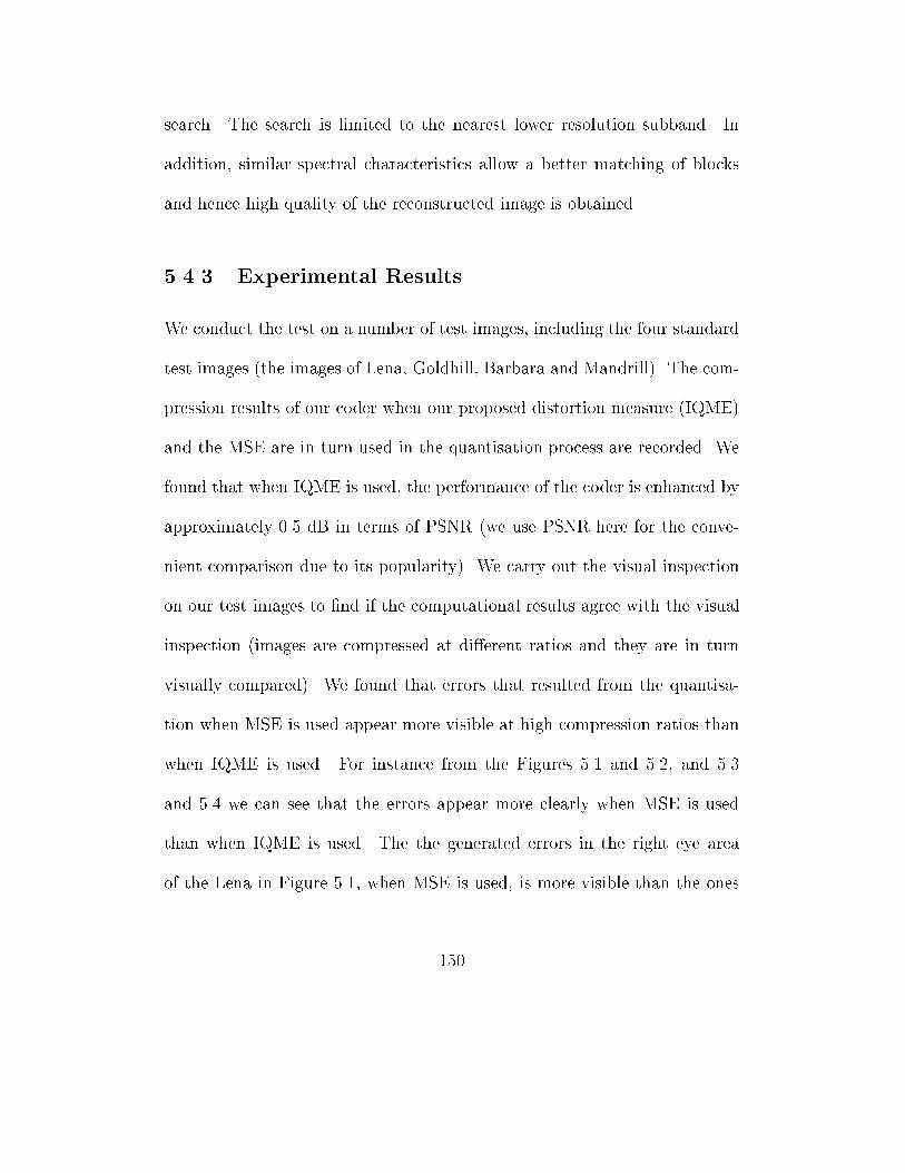
search. The search is limited to the nearest lower resolution subband. In
addition, similar spectral characteristics allow a better matching of blocks
and hence high quality of the reconstructed image is obtained.
5.4.3 Experimental Results
We conduct the test on a number of test images, including the four standard
test images (the images of Lena, Goldhill, Barbara and Mandrill). The com-
pression results of our coder when our proposed distortion measure (IQME)
and the MSE are in turn used in the quantisation process are recorded. We
found that when IQME is used, the performance of the coder is enhanced by
approximately 0.5 dB in terms of PSNR (we use PSNR here for the conve-
nient comparison due to its popularity). We carry out the visual inspection
on our test images to �nd if the computational results agree with the visual
inspection (images are compressed at di�erent ratios and they are in turn
visually compared). We found that errors that resulted from the quantisa-
tion when MSE is used appear more visible at high compression ratios than
when IQME is used. For instance from the Figures 5.1 and 5.2, and 5.3
and 5.4 we can see that the errors appear more clearly when MSE is used
than when IQME is used. The the generated errors in the right eye area
of the Lena in Figure 5.1, when MSE is used, is more visible than the ones
150
in Figure 5.2, when IQME is used. For Mandrill's reconstructed images,
the errors generated by IQIC1MSE appears more visible at the top left and
right sides of the �rst half, and in the left and right areas of in the middle
of the reconstructed image 5.3. Visually, we can see that the details of the
reconstructed image 5.4, when IQME is used, in the corresponding areas are
more visible. The whole reconstructed images 5.2 and 5.3 look better than
their corresponding 5.1 and 5.4. This con�rms that the performance of the
quantisation is better when IQME is used than MSE. In addition, the results
also show that our coder, constructed using IQME as a distortion measure
in the quantisation, performs better than the recently reported results from
a wavelet-fractal based coder constructed by Davis [Dav96]. The selected
experimental results are listed in Table 5.1.
We have shown that the employment of a good distortion measure in
quantisation can improve image coding. In the following section, we demon-
strate the usefulness of a good distortion measure in the selection of the best
wavelet packet bases.
151
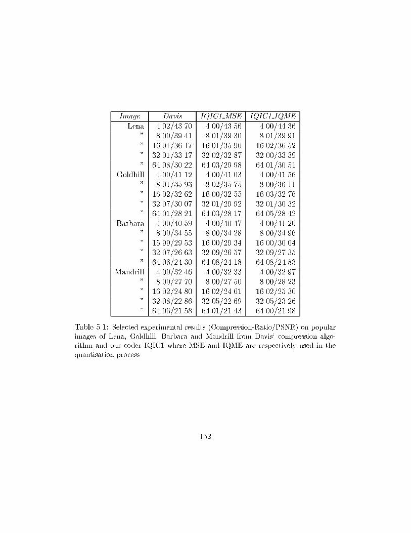
Image Davis IQIC1 MSE IQIC1 IQME
Lena 4.02/43.70 4.00/43.56 4.00/44.36
" 8.00/39.41 8.01/39.30 8.01/39.91
" 16.01/36.17 16.01/35.90 16.02/36.52
" 32.01/33.17 32.02/32.87 32.00/33.39
" 64.08/30.22 64.03/29.98 64.01/30.51
Goldhill 4.00/41.12 4.00/41.03 4.00/41.56
" 8.01/35.93 8.02/35.75 8.00/36.11
" 16.02/32.62 16.00/32.55 16.03/32.76
" 32.07/30.07 32.01/29.92 32.01/30.32
" 64.01/28.21 64.03/28.17 64.05/28.42
Barbara 4.00/40.59 4.00/40.47 4.00/41.20
" 8.00/34.55 8.00/34.28 8.00/34.96
" 15.99/29.53 16.00/29.34 16.00/30.04
" 32.07/26.63 32.09/26.57 32.09/27.35
" 64.06/24.30 64.08/24.18 64.08/24.83
Mandrill 4.00/32.46 4.00/32.33 4.00/32.97
" 8.00/27.70 8.00/27.50 8.00/28.23
" 16.02/24.80 16.02/24.61 16.02/25.30
" 32.08/22.86 32.05/22.69 32.05/23.26
" 64.06/21.58 64.01/21.43 64.00/21.98
Table 5.1: Selected experimental results (Compression-Ratio/PSNR) on popular
images of Lena, Goldhill, Barbara and Mandrill from Davis' compression algo-
rithm and our coder IQIC1 where MSE and IQME are respectively used in the
quantisation process
152
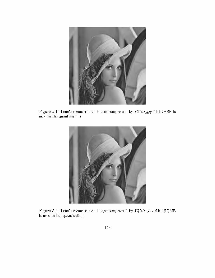
Figure 5.1: Lena's reconstructed image compressed by IQIC1MSE 64:1 (MSE is
used in the quantisation)
Figure 5.2: Lena's reconstructed image compressed by IQIC1IQME 64:1 (IQME
is used in the quantisation)
153
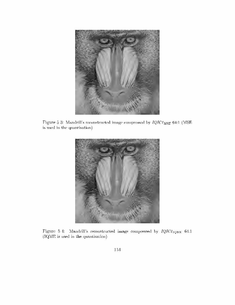
Figure 5.3: Mandrill's reconstructed image compressed by IQIC1MSE 64:1 (MSE
is used in the quantisation)
Figure 5.4: Mandrill's reconstructed image compressed by IQIC1IQME 64:1
(IQME is used in the quantisation)
154
5.5 Best Basis Selection Improvement with
IQME
The recent discovery of wavelet packets has lead to a new image compression
paradigm. The richness of the wavelet packet library allows to select the best
bases that optimally approximate a given signal of any time-frequency char-
acteristics, and hence higher compression can be obtained. Wavelet packets
provide more exibility and potential bene�t, however there are issues to be
resolved. Firstly, there is a need for a fast best wavelet packet basis selection
algorithm. Secondly, there is a need for an accurate distortion measure. The
requirement for a fast selection algorithm is due to the richness of the wavelet
packet library, and the requirement for an accurate distortion measure is due
to the condition to guarantee that the selected bases represent the given sig-
nal best in terms of human visual perception [LS98a].
The solution to the requirement for a fast wavelet packet basis selection
has been successfully answered and described in [CW92] and [RV93]. We
will show that the application of a distortion measure D1 that coincides with
human visual perception better than D2 in the best wavelet packet selec-
tion will result in better compression. We will apply our distortion measure
IQME and the MSE in the best wavelet packet basis selection algorithm of
our coder, called IQIC2 , respectively to experiment our conjecture.
155
Let IQIC2IQME and IQIC2MSE represent the coder, that will be described
in section 5.5.3, when IQME and MSE are used in the best wavelet packet
selection process respectively. We �rst review the lattice vector quantisa-
tion that will be employed in IQIC2. We then discuss the wavelet packet
theory and the best wavelet packet basis selection algorithm. Lastly we de-
scribe our coding algorithm from which our coder IQIC2 is constructed and
show the experimental results produced by IQIC2IQME and IQIC2MSE . We
demonstrate the bene�cial use of a good image quality evaluation method in
improving the selection of best bases by comparing the results of IQIC2IQME
and IQIC2MSE , and the results of IQIC2IQME and recently reported wavelet
and wavelet packet based coders.
5.5.1 Lattice Vector Quantisation
As discussed in chapter 3, there are a number of quantisation techniques that
can be used in image coding. VQ is considered to provide better reduction
of quantisation error than SQ in terms of visual perception. In addition,
each techniques has its own advantages and disadvantages. We choose the
lattice vector quantisation technique to implement the quantisers for IQIC2,
since this quantisation technique involves lower computational complexity
than nonuniform vector quantisation while it still provides comparable per-
156
formance [CS88, GG92, BSG+94]. Hence, we here review lattice vector quan-
tisation.
First we give an example of the simplest lattice that will enable us to
understand the essential concept of lattice vector quantisation.
The Zn lattice is de�ned as a set of points whose coordinates are integers
Zn = fy = (y1; y2; :::; yn) 2 Rn : yi 2 Zg (5.6)
In two dimensions, the lattice points are evenly distributed on a square grid,
and in 3 dimensions, on a cubic lattice. In this simple case, the vector
quantisation based on lattice Zn can be as follows:
1. The codebook is de�ned as a �nite subset of points in Zn. For instance,
we can select points as
C = fy = (y1; y2; :::; yn) 2 Zn :nXi=1
jyijp � mpg (5.7)
where m; p 2 N.
The lattice points make up the codewords in the codebook. The shape
of the class associated with each point is de�ned implicitly by the choice
of lattice. For example, we can �nd a straight interval [-1/2, 1/2] for
dimension n = 1, squares for n = 2 , and cubes for n = 3.
157
2. The quantisation algorithm for this simple case is elementary. The
representation of a source point (the point to be quantised) is the closest
integer. To quantise a vector, the search is for the closest integer to
each of the vector's components. For example, the source vector X =
(0.75,-1.15) is quantised by the reproduction vector Yi = (1,-1).
3. An index i and a binary code bi are assigned to each lattice vector Yi
for the transmission and decoding at the receiver.
In general, an n-dimensional lattice �, can be de�ned as a set of points Y
belonging to Rn, n 2 N, such that
� = fy 2 Rn : 9 (u1; u2; :::; un) 2 Zn; y =
nXi=1
uiaig (5.8)
where a1 ,a2 ,...,an are linearly independent vectors. These vectors belong to
an m-dimensional space Rm, and m � n.
There are a number of di�erent lattices and the most important one is
the lattice Dn that some other lattices, such as En lattice, are derived from
[CS88]. Dn lattice is de�ned by the following relationship
Dn = fy = (y1; y2; :::; yn) 2 Zn :nXi=1
yi = 0 g; n � 3 (5.9)
158
Lattices can be seen as solutions to problems of sphere packing in a space
[CS88], where the centers of the spheres de�ne the points in the lattice. The
reproduction vectors of a lattice vector quantiser correspond to the regularly
spaced lattice points, as de�ned by the relationship 5.7. A Voronoi class or
region Ci , refer section 3.2.2 and Figure 3.1 of chapter 3, is the set of points
lying closer to yi than to any other point in the lattice. With lattice vector
quantisation, the two main tasks need to be ful�lled are the choice of lattice
and the way to label the lattice points.
The choice of the optimum lattice is similar to the sphere packing the-
ory where it is searched to arrange the maximum number of spheres in a
given volume [CS88, GG92]. Since the lattice vector quantisation consists in
projecting the vectors of the input signal on a regular lattice of points, the
best lattice in the distortion sense will be the one that provides the highest
density of points [CS88, BSG+94]. For instance, for dimensions (3 � n � 5),
the lattice Dn gives the best density. For higher dimensions (6 � n � 8),
the lattices (En) give the best density and are de�ned as the union of Dn
lattices. For example, the E8 lattice is expressed as follows
E8 = D8(1=2[1] + D8) (5.10)
159
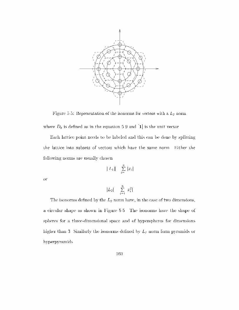
Figure 5.5: Representation of the isonorms for vectors with a L2 norm
where D8 is de�ned as in the equation 5.9 and [1] is the unit vector.
Each lattice point needs to be labeled and this can be done by splitting
the lattice into subsets of vectors which have the same norm. Either the
following norms are usually chosen
kL1k =nPi=1jxij
or
kL2k =nPi=1jx2i j
The isonorms de�ned by the L2 norm have, in the case of two dimensions,
a circular shape as shown in Figure 5.5. The isonorms have the shape of
spheres for a three-dimensional space and of hyperspheres for dimensions
higher than 3. Similarly the isonorms de�ned by L1 norm form pyramids or
hyperpyramids.
160
To determine the number of points lying on a sphere or a pyramid, the
following procedure is made
� In the case of L1: The evaluation of the number of ways of writing an
integer m as the sum of n absolute values.
� In the case of L2 : The evaluation of the number of ways of writing an
integer m as the sum of n squares.
That is the number of n-uples fxi; i = 1; :::; ng belonging to a given n-
dimensional lattice �, that verify
j x1 j+ :::+ j xn j = m (L1 norm) (5.11)
or
x2i + :::+ x
2n = m (L2 norm) (5.12)
The equations 5.11 and 5.12 are often called Lattice Point Equations.
In general, for any norm Lr , the number of solutions to its corresponding
lattice point equation is given by the coe�cients in the expansion series of
the following
1Xm=0
fV 2 �; kV kr = mg[zm] =1X
m=0
N�(m)qm (5.13)
161
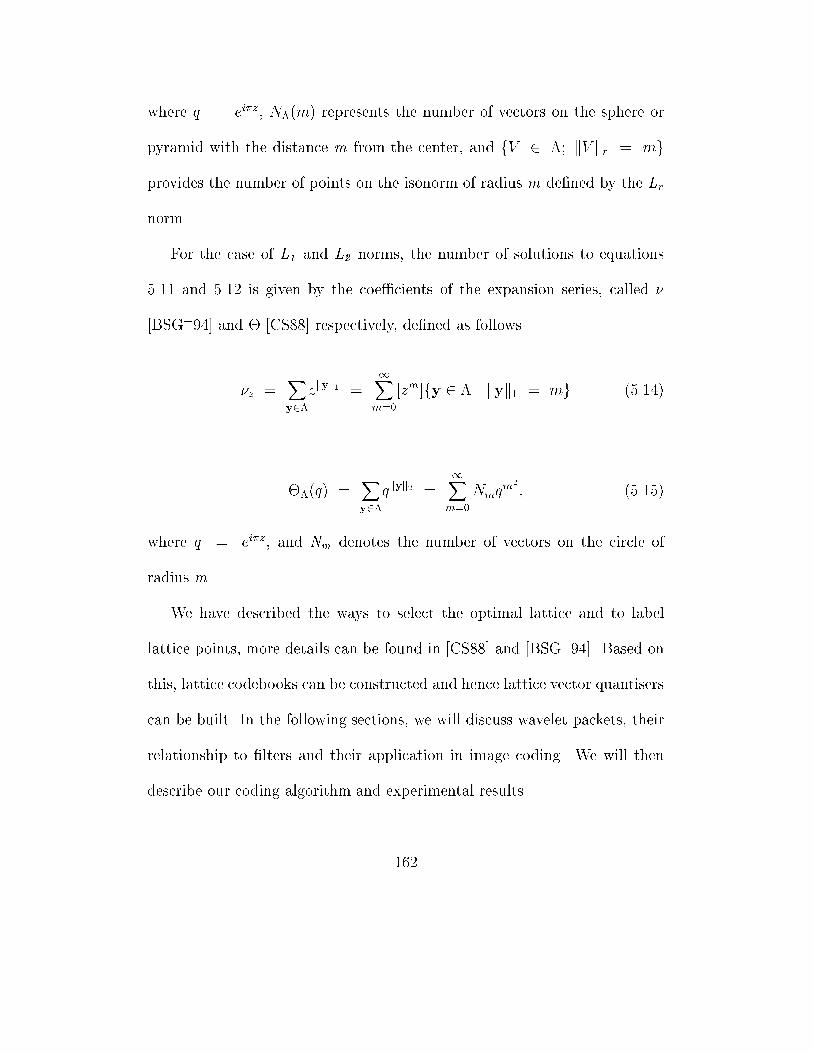
where q = ei�z, N�(m) represents the number of vectors on the sphere or
pyramid with the distance m from the center, and fV 2 �; kV kr = mg
provides the number of points on the isonorm of radius m de�ned by the Lr
norm.
For the case of L1 and L2 norms, the number of solutions to equations
5.11 and 5.12 is given by the coe�cients of the expansion series, called �
[BSG+94] and � [CS88] respectively, de�ned as follows
�z =Xy2�
zkyk1 =
1Xm=0
[zm]fy 2 � j kyk1 = mg (5.14)
��(q) =Xy2�
qkyk2 =
1Xm=0
Nmqm2
; (5.15)
where q = ei�z, and Nm denotes the number of vectors on the circle of
radius m.
We have described the ways to select the optimal lattice and to label
lattice points, more details can be found in [CS88] and [BSG+94]. Based on
this, lattice codebooks can be constructed and hence lattice vector quantisers
can be built. In the following sections, we will discuss wavelet packets, their
relationship to �lters and their application in image coding. We will then
describe our coding algorithm and experimental results.
162
5.5.2 Wavelet Packets
Wavelet transform is important for many applications due to its ability to
provide useful time-frequency localisations. The hierarchical wavelet image
representation also allows quantisation strategies to be improved for exploit-
ing the space-frequency characteristics of wavelet coe�cients [Sha93]. How-
ever, if the time-frequency characteristics of a given signal do not match
the time-frequency localisations o�ered by the wavelet, there is a mismatch
which results in an ine�cient decomposition. Attempts have been made to
overcome this problem and this has lead to the discovery of wavelet packets
[CMQW92].
Wavelet packets, which can be described as arbitrary subband decompo-
sition trees, conceptually are an elegant generalisation of wavelets. These ar-
bitrary subband decomposition trees form a rich library of transforms, which
includes both the full-band Short-Time-Fourier-Transform and wavelet trees,
that have several attractive features. They can be e�ciently implemented
using �lter band structures and o�er a very large library of orthogonal linear
expansions [CMQW92]. The richness of wavelet packet library allows a basis
that best represents a given signal or a collection of signals to be selected,
hence high compression can be achieved [RV93, XRO94]. This also o�ers
considerable exibility than orthogonal or biorthogonal wavelets when these
163
type of wavelets are used to represent signals of a diverse time-frequency
characteristics [XRO94].
Wavelet packets were introduced recently by Coifman et al : as a family
of orthonormal bases, including the wavelet basis and Short-Time-Fourier-
Transform (STFT)-like basis [CW92]. Wavelet packets represent a general-
isation of multiresolution decomposition and comprise the entire family of
subband tree decompositions. They o�er access to a rich library of orthonor-
mal bases from which the best bases can be chosen for a given signal. For
example, the complete decomposition of a discrete image sequence in RN�N
as a full wavelet packet analysis tree of depth logN as shown in Figure 5.6.
Each parent node has four children, signifying the four bands (LL, LH, HL
and HH). The tree root refers to the original image and a leaf corresponds
to a subband. For an orthonormal subband decomposition, any subtree (a
pruned subtree of the full tree) is a valid orthonormal basis, and represents a
generalisation of the logarithmic subtree decomposition associated with the
wavelet transform. There is thus an obvious isomorphism between the set of
of orthonormal wavelet packet bases and the set of pruned subtrees of the
full tree, and the best wavelet packet basis search is equivalent to �nding the
optimally pruned subtree [XRO94].
164
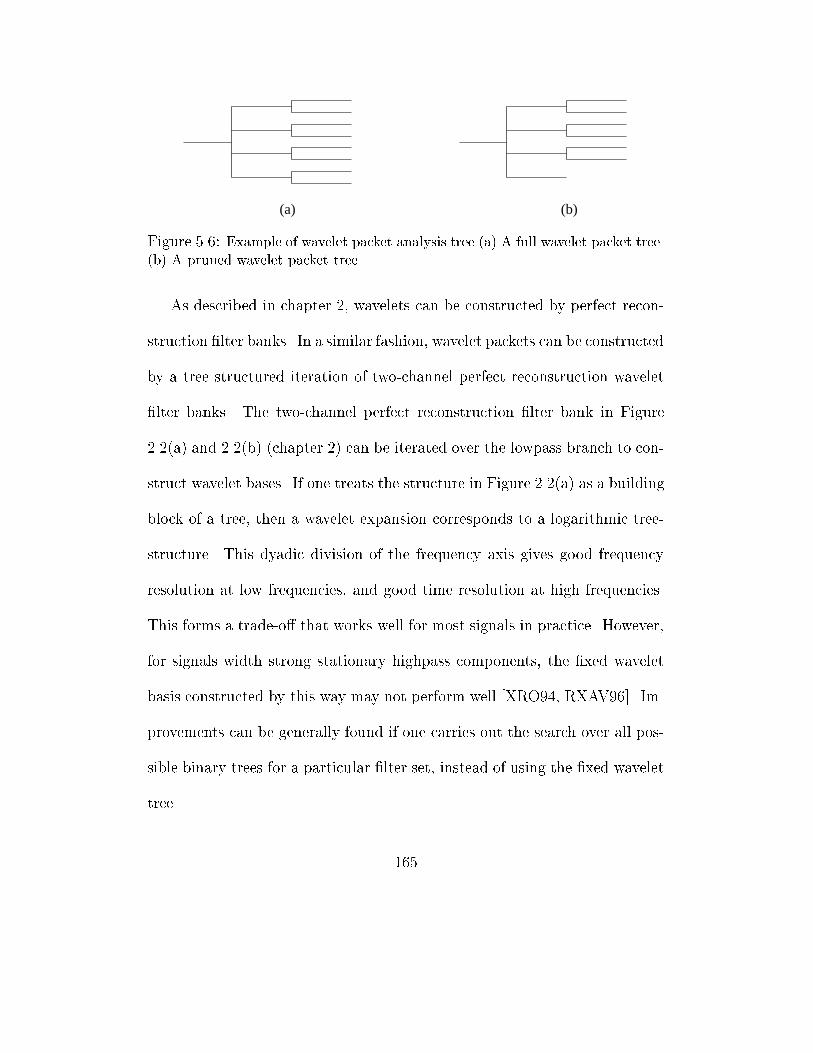
(b)(a)
Figure 5.6: Example of wavelet packet analysis tree (a) A full wavelet packet tree.
(b) A pruned wavelet packet tree
As described in chapter 2, wavelets can be constructed by perfect recon-
struction �lter banks. In a similar fashion, wavelet packets can be constructed
by a tree structured iteration of two-channel perfect reconstruction wavelet
�lter banks. The two-channel perfect reconstruction �lter bank in Figure
2.2(a) and 2.2(b) (chapter 2) can be iterated over the lowpass branch to con-
struct wavelet bases. If one treats the structure in Figure 2.2(a) as a building
block of a tree, then a wavelet expansion corresponds to a logarithmic tree-
structure. This dyadic division of the frequency axis gives good frequency
resolution at low frequencies, and good time resolution at high frequencies.
This forms a trade-o� that works well for most signals in practice. However,
for signals width strong stationary highpass components, the �xed wavelet
basis constructed by this way may not perform well [XRO94, RXAV96]. Im-
provements can be generally found if one carries out the search over all pos-
sible binary trees for a particular �lter set, instead of using the �xed wavelet
tree.
165
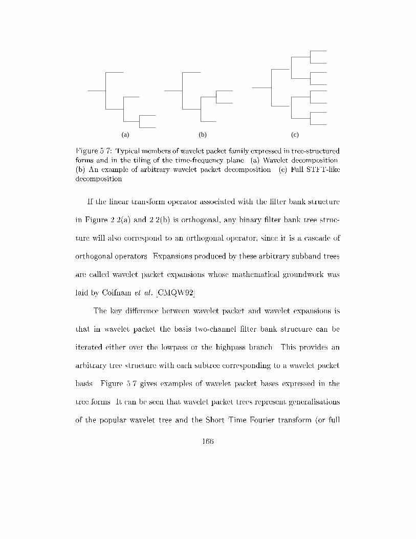
(c)(a) (b)
Figure 5.7: Typical members of wavelet packet family expressed in tree-structured
forms and in the tiling of the time-frequency plane. (a) Wavelet decomposition.
(b) An example of arbitrary wavelet packet decomposition. (c) Full STFT-like
decomposition
If the linear transform operator associated with the �lter bank structure
in Figure 2.2(a) and 2.2(b) is orthogonal, any binary �lter bank tree struc-
ture will also correspond to an orthogonal operator, since it is a cascade of
orthogonal operators. Expansions produced by these arbitrary subband trees
are called wavelet packet expansions whose mathematical groundwork was
laid by Coifnam et al : [CMQW92].
The key di�erence between wavelet packet and wavelet expansions is
that in wavelet packet the basis two-channel �lter bank structure can be
iterated either over the lowpass or the highpass branch. This provides an
arbitrary tree structure with each subtree corresponding to a wavelet packet
basis. Figure 5.7 gives examples of wavelet packet bases expressed in the
tree forms. It can be seen that wavelet packet trees represent generalisations
of the popular wavelet tree and the Short Time Fourier transform (or full
166
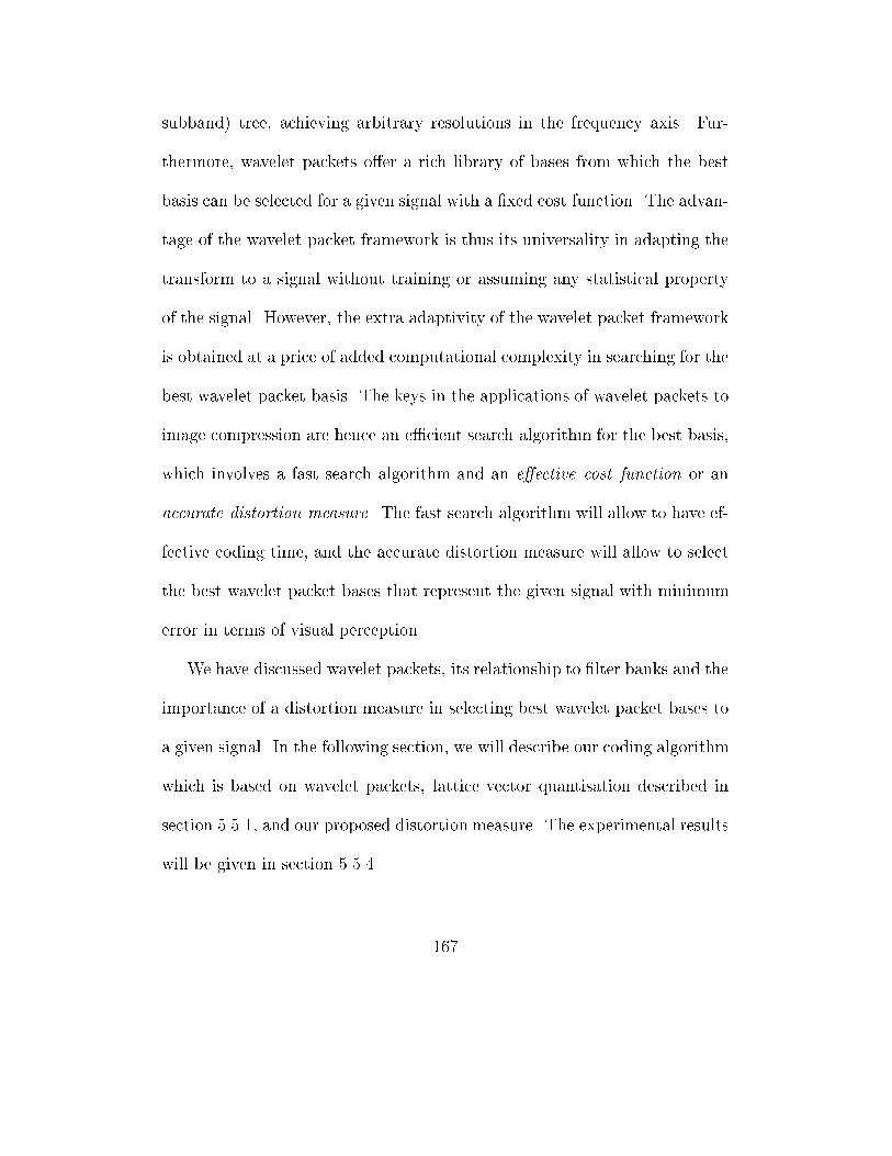
subband) tree, achieving arbitrary resolutions in the frequency axis. Fur-
thermore, wavelet packets o�er a rich library of bases from which the best
basis can be selected for a given signal with a �xed cost function. The advan-
tage of the wavelet packet framework is thus its universality in adapting the
transform to a signal without training or assuming any statistical property
of the signal. However, the extra adaptivity of the wavelet packet framework
is obtained at a price of added computational complexity in searching for the
best wavelet packet basis. The keys in the applications of wavelet packets to
image compression are hence an e�cient search algorithm for the best basis,
which involves a fast search algorithm and an e�ective cost function or an
accurate distortion measure. The fast search algorithm will allow to have ef-
fective coding time, and the accurate distortion measure will allow to select
the best wavelet packet bases that represent the given signal with minimum
error in terms of visual perception.
We have discussed wavelet packets, its relationship to �lter banks and the
importance of a distortion measure in selecting best wavelet packet bases to
a given signal. In the following section, we will describe our coding algorithm
which is based on wavelet packets, lattice vector quantisation described in
section 5.5.1, and our proposed distortion measure. The experimental results
will be given in section 5.5.4.
167
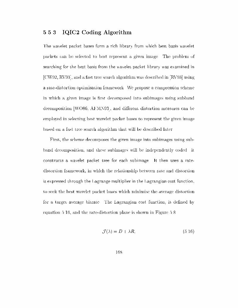
5.5.3 IQIC2 Coding Algorithm
The wavelet packet bases form a rich library from which best basis wavelet
packets can be selected to best represent a given image. The problem of
searching for the best basis from the wavelet packet library was examined in
[CW92, RV93], and a fast tree search algorithm was described in [RV93] using
a rate-distortion optimisation framework. We propose a compression scheme
in which a given image is �rst decomposed into subimages using subband
decomposition [WO86, AFMN93], and di�erent distortion measures can be
employed in selecting best wavelet packet bases to represent the given image
based on a fast tree search algorithm that will be described later.
First, the scheme decomposes the given image into subimages using sub-
band decomposition, and these subimages will be independently coded. it
constructs a wavelet packet tree for each subimage. It then uses a rate-
distortion framework, in which the relationship between rate and distortion
is expressed through the Lagrange multiplier in the Lagrangian cost function,
to seek the best wavelet packet bases which minimise the average distortion
for a target average bitrate. The Lagrangian cost function, is de�ned by
equation 5.16, and the rate-distortion plane is shown in Figure 5.8.
J (�) = D + �R; (5.16)
168
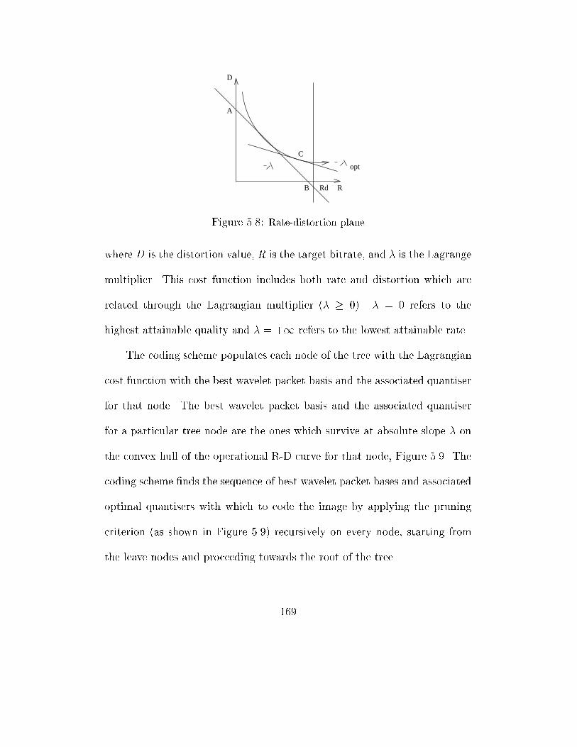
C
opt
A
D
RRdB
Figure 5.8: Rate-distortion plane
where D is the distortion value, R is the target bitrate, and � is the Lagrange
multiplier. This cost function includes both rate and distortion which are
related through the Lagrangian multiplier (� � 0). � = 0 refers to the
highest attainable quality and � = +1 refers to the lowest attainable rate.
The coding scheme populates each node of the tree with the Lagrangian
cost function with the best wavelet packet basis and the associated quantiser
for that node. The best wavelet packet basis and the associated quantiser
for a particular tree node are the ones which survive at absolute slope � on
the convex hull of the operational R-D curve for that node, Figure 5.9. The
coding scheme �nds the sequence of best wavelet packet bases and associated
optimal quantisers with which to code the image by applying the pruning
criterion (as shown in Figure 5.9) recursively on every node, starting from
the leave nodes and proceeding towards the root of the tree.
169
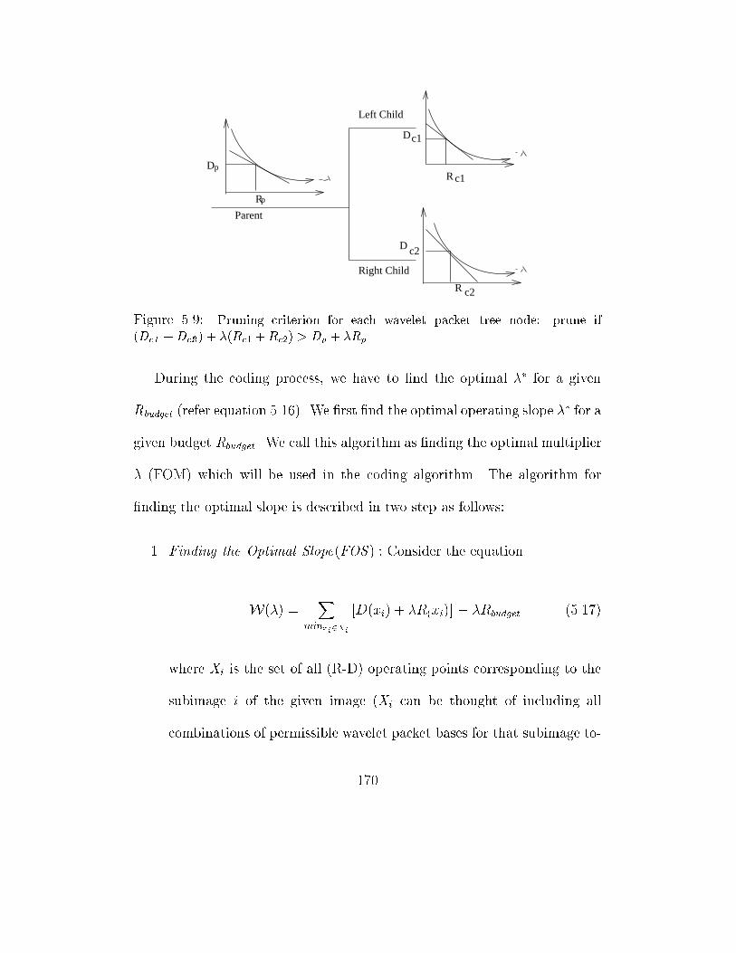
D
R
p
p
D
c2R
Dc1
R c1
Parent
Left Child
Right Child
c2
Figure 5.9: Pruning criterion for each wavelet packet tree node: prune if
(Dc1 +Dc2 ) + �(Rc1 +Rc2) > Dp + �Rp
During the coding process, we have to �nd the optimal �� for a given
Rbudget (refer equation 5.16). We �rst �nd the optimal operating slope �� for a
given budget Rbudget. We call this algorithm as �nding the optimal multiplier
� (FOM) which will be used in the coding algorithm. The algorithm for
�nding the optimal slope is described in two step as follows:
1. Finding the Optimal Slope(FOS ) : Consider the equation
W(�) =X
minxi2Xi
[D(xi) + �R(xi)] � �Rbudget (5.17)
where Xi is the set of all (R-D) operating points corresponding to the
subimage i of the given image (Xi can be thought of including all
combinations of permissible wavelet packet bases for that subimage to-
170
gether with their associated quantisation choices). We �nd the optimal
operating slope by �nding the maximum of W (�) (the optimal slope is
actually the inverse of the maximum of W (�)).
From equation 5.17, we can �nd the derivative of W, @W/@�.
@W=@� =Xi
R�
i (�)�Rbudget (5.18)
where R�
i (�) is the rate associated with the chosen wavelet packet basis
and quantiser for subimage i .
Due to the discrete nature of the problem, the number of singular values
of � is �nite and the optimal slope �� which maximisesW corresponds
to a singular value of �. That is we simply have to �nd the optimal
operating point and this is described in the next step.
2. Finding the Optimal Point (FOP): The optimal points can be found
by the following steps:
� Step 1: Pick �h � �l such thatP
iR�
i (�h) � Rbudget �P
iR�
i (�l)3.
If the inequality above is an equality for either slope value, then stop,
since we have an exact solution. Otherwise, proceed to Step 2.
3These value can be chosen. For example, we can simply choose �l = 0 and �h = +1.
Since � = 0 corresponds to the highest attainable quality,P
iR�
i (0) � Rbudget. Similarly,
� = +1 corresponds to the lowest attainable rate,P
i R�
i (+1) � Rbudget
171
� Step 2: Compute �next
�next j(P
i[D�
i (�l) � D�
i (�h)]) = (P
i[R�
i (�l) � R�
i (�h)])j+ �.
Where � is a very small positive number used to ensure that the lower
rate point is picked if �next is a singular slope value.
� Step 3: Run the optimal operating slope algorithm, the FOS, for
�next.
if (P
iR�
i (�next) =P
iR�
i (�h))
then f
� = �h.
stop.
g
else f
if (P
iR�
i (�next) > Rbudget)
then
�l �next.
else
�h �next.
Go to Step 2.
g
172
We will present the description of the coding algorithm from which our coder
IQIC2 is based on. We de�ne the following terms used in the description of
the algorithm:
� T : The complete wavelet packet tree for each subimage.
� S : � T , pruned subtree of T , i.e., any admissible wavelet packet bases
subtree.
� ~S: Set of leaves or terminal nodes of subtree S .
� n ij ; bij ; cij : The j th node, basis, and coe�cient vector respectively, at the
ith tree-depth. The bij represents the basis members associated with node nij
while cij represents the inner product of the signal with the basis vectors in
bij . To simplify notation, we will drop the subscripts i ; j when not necessary.
� qv(n): The set of lattice vector quantisers used for node n 2 T .
� Qv(S): Vector set of all admissible lattice vector quantisers for the collec-
tion of individual leaf nodes of subtree S .
� Dq(n), Rq(n): Distortion and rate respectively, for wavelet packet coe�-
cient vector cn of node n using quantiser q 2 qv(n).
We �nd the best wavelet packet bases and the quantisers from the set
of permissible quantisers such that the total Lagrangian cost is minimised.
Namely
J (S; �) = minS�TminQ2Qv(S)[DQ(S) + �RQ(S)] (5.19)
173
The coding procedure is applied to each individual subimage and can be run
in parallel. It is as follows:
First we de�ne a data structure of the form fRij, D
ij, J
ij, split(n
ij )g that
associates with every node n ij . Rij refers to the rate, Di
j refers to the dis-
tortion, J ij refers to the Lagrangian cost associated with the optimal subtree
(for a given �) rooted at n ij , and split(n ij ) is a boolean variable re ects the
decision of whether or not to split the node into its children branches. The
coding procedure is described in a number of steps
� Step 1: Generate the coe�cients cij for the entire wavelet packet family.
� Step 2:
- Gather the given set of quantisers for all the nodes of the wavelet
packet tree T .
- Generate the R versus D points in the rate-distortion plane (refer
Figure 5.8) for each node n ij of the tree based on (Rq(nij );Dq(n
ij )).
- Invoke the FOM algorithm to �nd the optimal �.
� Step 3: For the current �, populate all the nodes n ij of the tree with
their minimum Lagrangian costs Jn(�) (i.e., Jn(�) = minq[Dq(n) +
�Rq(n)]).
174
� Step 4: Let d = log(N ) denote the maximum tree depth. Let i = d
(initialise i). If Jn(�) is minimised with a qn 2 qv(n), then initialise
Rdj Rd
j (where Rdj = Rq(n));
Ddj Dd
j (where Ddj = Dq(n));
Jdj J
dj ;
� Step 5: if (i < 0 ) then Go to Step 7, else i (i � 1 ).
� Step 6: 8j = 1; 2; :::; 2i at ith tree level:
if (Jdj < Ji+12j�1 + J
i+12j )
then f
split(n ij ) FALSE;
Rdj Rd
j ;
Ddj Dd
j ;
Jdj J
dj ;
g else f
split(n ij ) TRUE;
Rij (Ri+1
2j�1 + Ri+12j );
Dij (D i+1
2j�1 + D i+12j );
Jij (J i+1
2j�1 + J i+12j );
g
Go to Step 5.
175
� Step 7: Starting from the root n0 and using the node data structure
element split (node) (which has TRUE values, i.e., the ones selected)
for all the nodes of the tree T , to mark out the optimal subtrees S �(�)
and its associated optimal quantiser choice Q�(�) 2 Qa(S�(�)).
The above formal coding algorithm can be explained as follows:
Initially, the given image is decomposed into subimages. For each subimage,
the wavelet packet tree is �rst grown. Each tree is then populated with the
Lagrangian cost. At each parent node, a split/merge decision is made based
on the comparison of the cost of the parent and the sum of the costs of its
children. If the parent cost is small, its children are pruned. The pruning
process is illustrated as in Figure 5.9. The tree pruning process starts re-
cursively from the leaf nodes and proceeds towards the root node. In the
end, a pruned subtree is obtained for a �xed �. The best � is obtained using
the Finding Optimal Operating Slope (FOS) and the Finding Optimal Point
(FOP) procedures (as described previously). The criterion used in the choice
of the lattice vector quantisers and in the best wavelet packet basis selection
algorithm (the tree pruning algorithm) is based only on a mathematical dis-
tortion. We in turn use IQME and MSE as the required distortion measure
to experiment our conjecture.
176
The problem is then of minimising a visual distortion D under the con-
straint of a given bit rate Rbudget by using two di�erent distortion measures,
our IQME and the classical MSE, to select the best wavelet packet bases. We
employ IQME in IQIC2IQME and MSE in IQIC2MSE to compress a number
of images and compare the results produced by IQIC2IQME and IQIC2MSE .
The results from from IQIC2IQME are also compared to the recently reported
wavelet and wavelet packet based coders. The selected results of the test on
standard images of Lena, Barbara, Mandrill and Goldhill are shown in the
following section.
5.5.4 Experimental Results
We carried out our experiments on the test set of grey-scale images on a
dual-processor Sun Sparc machine of 125 MHz, and it approximately takes
57 seconds to encode an image of 512 by 512 bytes and 18 seconds to de-
code it. The selected results of the four popular images (Lena, Barbara,
Goldhill and Mandrill), when IQME and MSE are used in the best wavelet
packet basis selection algorithm, are listed in Table 5.2. The results from
JPEG [Wal91] and EPIC [SA97] are also listed in the table for comparison
to IQIC2 coder.
177
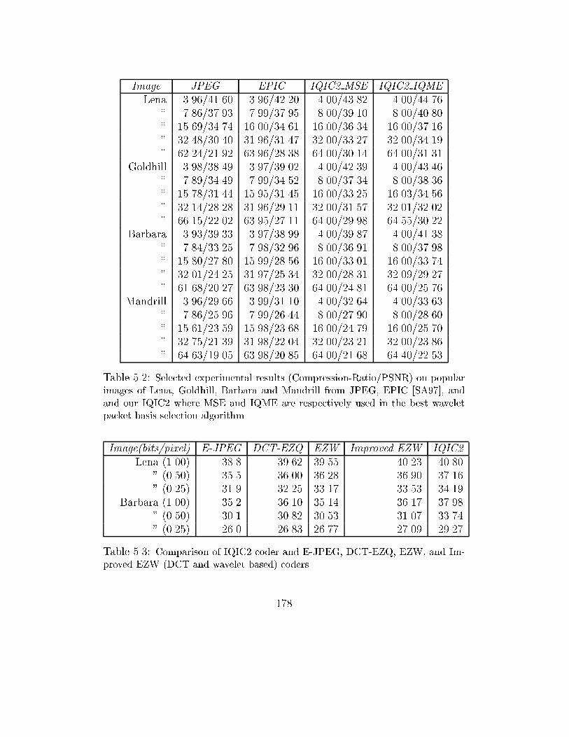
Image JPEG EPIC IQIC2 MSE IQIC2 IQME
Lena 3.96/41.60 3.96/42.20 4.00/43.82 4.00/44.76
" 7.86/37.93 7.99/37.95 8.00/39.10 8.00/40.80
" 15.69/34.74 16.00/34.61 16.00/36.34 16.00/37.16
" 32.48/30.40 31.96/31.47 32.00/33.27 32.00/34.19
" 62.24/21.92 63.96/28.38 64.00/30.14 64.00/31.31
Goldhill 3.98/38.49 3.97/39.02 4.00/42.39 4.00/43.46
" 7.89/34.49 7.99/34.52 8.00/37.34 8.00/38.36
" 15.78/31.44 15.95/31.45 16.00/33.25 16.03/34.56
" 32.14/28.28 31.96/29.11 32.00/31.57 32.01/32.02
" 66.15/22.02 63.95/27.11 64.00/29.98 64.55/30.22
Barbara 3.93/39.33 3.97/38.99 4.00/39.87 4.00/41.38
" 7.84/33.25 7.98/32.96 8.00/36.91 8.00/37.98
" 15.80/27.80 15.99/28.56 16.00/33.01 16.00/33.74
" 32.01/24.25 31.97/25.34 32.00/28.31 32.09/29.27
" 61.68/20.27 63.98/23.30 64.00/24.81 64.00/25.76
Mandrill 3.96/29.66 3.99/31.10 4.00/32.64 4.00/33.63
" 7.86/25.96 7.99/26.44 8.00/27.90 8.00/28.60
" 15.61/23.59 15.98/23.68 16.00/24.79 16.00/25.70
" 32.75/21.39 31.98/22.04 32.00/23.21 32.00/23.86
" 64.63/19.05 63.98/20.85 64.00/21.68 64.40/22.53
Table 5.2: Selected experimental results (Compression-Ratio/PSNR) on popular
images of Lena, Goldhill, Barbara and Mandrill from JPEG, EPIC [SA97], and
and our IQIC2 where MSE and IQME are respectively used in the best wavelet
packet basis selection algorithm
Image(bits/pixel) E-JPEG DCT-EZQ EZW Improved EZW IQIC2
Lena (1.00) 38.8 39.62 39.55 40.23 40.80
" (0.50) 35.5 36.00 36.28 36.90 37.16
" (0.25) 31.9 32.25 33.17 33.53 34.19
Barbara (1.00) 35.2 36.10 35.14 36.17 37.98
" (0.50) 30.1 30.82 30.53 31.07 33.74
" (0.25) 26.0 26.83 26.77 27.09 29.27
Table 5.3: Comparison of IQIC2 coder and E-JPEG, DCT-EZQ, EZW, and Im-
proved EZW (DCT and wavelet based) coders
178
In Table 5.3, the coding results for both Lena and Barbara at di�erent
rates are listed. For comparison purpose, we include in this table the results
from enhanced JPEG (E-JPEG) [WG93], DCT-based coder with embedded
zerotree quantiser [XGO96], Shapiro's embedded zerotree wavelet algorithm
(EZW) coder [Sha93], and the improved EZW coder in [SP96]. Only bi-
trates of 1, 0.5 and 0.25 b/p are included due to the results extracted from
the referenced papers.
The results from our experiment con�rm our conjecture that a better
distortion measure can be used in the best basis selection algorithm to im-
prove image coding. Our experimental results from IQIC2 in each case when
IQME and MSE are used proves our idea, and also our visual inspection
based on the mean-opinion-score con�rms the correctness of our conjecture.
If we visually inspect the Figures 5.10 and 5.11, and Figures 5.12 5.13 (the
two selected reconstructed images of Lena and Mandrill images compressed
at the ratio 64:1 by IQIC2IQME and IQIC2MSE), we can �nd that errors
that resulted from IQIC2MSE appear more visible than ones resulted from
IQIC2IQME . For example, the generated errors in the nose and mouth areas
of Lena's reconstructed images 5.10 and 5.11. Also, the generated errors in
the nose area of the Mandrill in Figure 5.12, when MSE is used, is more
visible than the ones in Figure 5.13, when IQME is used.
179
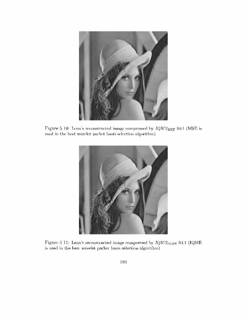
Figure 5.10: Lena's reconstructed image compressed by IQIC2MSE 64:1 (MSE is
used in the best wavelet packet basis selection algorithm)
Figure 5.11: Lena's reconstructed image compressed by IQIC2IQME 64:1 (IQME
is used in the best wavelet packet basis selection algorithm)
180
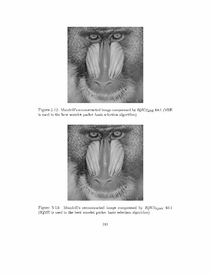
Figure 5.12: Mandrill's reconstructed image compressed by IQIC2MSE 64:1 (MSE
is used in the best wavelet packet basis selection algorithm)
Figure 5.13: Mandrill's reconstructed image compressed by IQIC2IQME 64:1
(IQME is used in the best wavelet packet basis selection algorithm)
181
5.6 Conclusion
Digital images posses characteristics of being both data extensive and rela-
tively redundant objects that make them an obvious target for compression.
The increasing number of digital image applications has also put a strong de-
mand for higher compression methods. In this chapter, we have generalised
the two main approaches of image coding as the inverse problem. The ulti-
mate goal of image compression can be then described as the search for the
solution to the inverse problem from which digital images can be represented
by a small set of functions or coe�cients of functions that require minimum
digital bits. We have also pointed out that the performance of coders based
on either of these approaches depends on the quantisation strategy and best
basis selection algorithm used in those coders. However, the success of a
quantisation strategy or a best basis selection algorithm depends on the em-
ployed distortion measure. This implies that image coding gain in general
depends on the distortion measure in use.
We have mathematically shown that the application of a distortion mea-
sure D1 that coincides with human visual perception better than the distor-
tion D2 , in the quantisation or best basis selection algorithm employed by a
lossy compression technique, can result in better compression. We have de-
veloped and implemented two compression algorithms in which our distortion
182
measure (IQME) is used in the quantisation process of the �rst algorithm
and in the best wavelet packet selection of the second algorithm. We found
that when IQME is used the compression gain is approximately above 0.5 dB
higher than when MSE is employed in the same algorithms. Our experimen-
tal results and mathematical analysis con�rm that image quality measure
is an important factor in improving image coding. In comparison with the
results from the recently reported coders we found that our coders provide
higher compression. The IQIC1IQME performs better than Davis' fractal-
wavelet based coder. Our wavelet packet based coder, IQIC2IQME , with the
support of our image quality measure also shows its advantages over the two
important coders, the DCT-based coder with embedded zerotree quantisa-
tion [XGO96] and the improved EZW coder [SP96].
In summary, in this chapter we have proposed two new image compression
algorithms based on our image quality measure. The experimental results
showed that high compression can be obtained. This not only proved the
validity of our proposed image quality measures described in chapter 4, but
also showed the success of our investigation in using image quality measure
to improve image coding.
183
Chapter 6
Multi-Level Browsing for
E�cient Image Transmission
6.1 Introduction
The global information infrastructure brings about the integration, manage-
ment, and communication of gigabytes of data in parallel and distributed
environments over national and international networks. The Wide World
Web (WWW) has provided users with access to data of di�erent media such
as voice, image and video over the Internet. Data objects such as images
are important in many systems such as image and multimedia databases,
digital libraries, remote sensing systems, geographical information systems,
184
teleshopping and telebrowsing systems. Unfortunately, image objects are
large in size, hence they need more storage space and have long transmission
time. The inherently distributed nature of these image repositories results
in communication being a bottleneck in the current network scenario. Mul-
timedia applications such as distributed digital libraries, digital databases,
teleshopping and telebrowsing systems are expected to deliver as minimum
data as needed and allow users to quickly browse through images located
in remote image repositories [SSL97]. However, currently users often ex-
perience delays. This is because a large amount of image data has to be
transmitted across networks by a high number of users and the existing net-
work technologies are not advanced enough to deal with this situation. The
network bandwidth in many places is not high enough and users in those
places still access remote image repositories via slow communication lines.
Network technologies such as ATM, FDDI, DQDB, etc. are being developed
to provide better bandwidth and more e�cient communication. However, the
growing number of users, especially the increasing number of mobile users
accessing the Internet via slow wireless links, makes the communication bot-
tleneck problem remain serious in the present and possibly many years in the
future.
185
The communication bottleneck problem (Cp) is in general contributed
by three main factors, namely, the network bandwidth (Bn), the number of
network users and applications that require image transmission (Nu), and
the volume of requested image data (Vi). The communication bottleneck
problem can be de�ned as a relationship to these three factors as
Cp �Nu � ViBn
(6.1)
In order to minimise Cp one can either increase Bn , or decrease Nu or Vi .
Since it is not realistic to reduce the number of users and applications (Nu),
one can either try to minimise Cp by increasing Bn or decreasing the vol-
ume of image data being delivered (Vi). Although network technology will
be enhanced with new developments and better communication links will
be used to replace the current slow ones. However, in the context of the
rapidly increasing number of users and applications with high demand on
image information, we believe that it is more important to reduce the vol-
ume of requested images. We suggest that the volume of requested images
be minimised before delivery. This will alleviate the the increasingly critical
communication delays.
Currently there are two popular methods for reducing the transmission
time of images.
186
� Images are compressed to reduce their size before transmission and the
compressed images are decompressed at the receiving site.
� An image is progressively transmitted in a number of steps by which
the quality of the reconstructed image is enhanced after each step.
We can observe that the bandwidth usage can be improved if the volume
of requested images is minimised before transmission. This can be done
if users and applications can specify the quality of requested images, and
images are either pre-compressed at the desired quality or further compressed
according to the speci�ed quality. This chapter �rst discusses the advantages
and disadvantages of image compression and progressive image transmission
methods, then proposes a multi-level browsing framework as a solution to the
image transmission problem. The main research focus is to �nd a proper way
to minimise image data before transmission while this still meets the users
and applications' requirement well. From this proposed idea, browsers and
network graphical user interfaces can be built to work together with di�erent
image compression and image quality methods to allow users to specify the
level of quality of the images they need and to ensure that only required data
is delivered.
187
6.2 Data Reduction with Image Compression
The size of a digital image can be reduced by using a proper information
coding scheme or image compression method (since most images contain cer-
tain level of redundancy or some part of an image can be derived from the
other parts [LS98b], it is possible to reduce the size of an image by removing
redundant parts in the image. One can also represent the image in a form
that requires less storage and from which the image can be reconstructed
without loss or with an acceptable level of loss of information). Images can
be either compressed by a lossy or lossless compression algorithm, depend-
ing on the application, and many image compression techniques have been
devised which we reviewed in chapter 3. The most popular method is JPEG
compression technique which is based on Discrete Cosine Transform [Wal91].
JPEG allows images to be compressed at relatively high compression ratios,
(e.g., images can be compressed at ratio 15 to 1 and the reconstructed im-
ages still have high quality - almost indistinguishable by human eyes) while
still remains an acceptable level of quality. Other image compression meth-
ods have also been proposed and they aim to provide higher compression
so that the size of images can be better reduced. Examples of some of the
most focused image compression methodologies are image compression with
vector quantisation [WBBW88, SG92, CGV96], fractal based image coding
188
[BJ88, Jac90, Fis95], and image compression based on wavelet and wavelet
packet [ABMD92, DJL92, Sha93, RV93, XRO94].
Image compression based on wavelet [Sha93], wavelet packet [XRO94],
fractal [Fis95], and fractal-wavelet [Dav96] can have higher compression than
the standard JPEG, however these algorithms have longer coding time in
comparison to JPEG. This indicates that JPEG is still useful for applica-
tions which require fast image coding. In applications where communication
links are slow and images need to be transmitted across networks, wavelet-
based image compression tends to be more useful. In addition, under some
circumstances, a dynamic use of di�erent compression algorithms may be of
more bene�cial. For example, if images have to be transmitted across net-
works via very slow links and the quality of the requested image is lower
than the quality of the currently stored image, further compression with
fast compression algorithm can reduce the volume of image data, and hence
transmission time can be reduced.
To alleviate the image transmission problem by using only compression
is far from optimal, since images are often pre-compressed, stored and trans-
mitted on request. The quality of the stored images may be higher than
the quality of requested images, hence extra data may have to be transmit-
ted unnecessarily. In order to reduce the volume of transmitted image data
189
as much as possible, researchers have come up with the idea of progressive
transmission by which images are transmitted in a number of steps and the
transmission process can be terminated by the user. This will be discussed
in the next section.
6.3 Progressive Image Transmission
The volume of image data can be reduced before transmission by using image
compression. To further reduce it, images can be progressively transmitted.
The main idea is that the whole image is transmitted in a number of steps.
First, an approximate version of the entire image is transmitted so that its
structural information is sent early in the transmission. The quality of the im-
age is then progressively improved by a number of other transmission passes
[HT86, OZV94]. The transmission is either terminated early by the user or
on the completion of the transmission of the �nal pass. If the transmission
is terminated early by the user, then the amount of data to be delivered is
reduced.
Progressive image transmission (PIT) has been studied for many years
[WG89] and this �eld will continue to evolve. PIT often incorporates image
compression aimed to achieve high compression ratio with low complexity
while allowing the most important information to be transmitted as early
190
as possible in order to make better usage of the bandwidth by users' early
termination. The early PIT work based on spatial domain was carried out by
Sloan and Tanimoto [ST79]. The transform coding schemes have also allowed
data to appear in a suitable form for e�cient transmission. For instance, in
the JPEG image compression where transform coe�cients are concerned, the
simple approach is to send block DC coe�cients �rst and send other coef-
�cients at later stages. The best order for sending other coe�cients was
found by Ngan [Nga84]. For images of general structure, transmission and
reconstruction following the conventional zig-zag scanning pro�le is found
to be e�cient. For those images with signi�cant edge details, which causes
large magnitude coe�cients to cluster along the horizontal or vertical bor-
ders of the coe�cient domain, it is best to send coe�cients in those locations
�rst. An alternative technique is to design bit allocation maps and associated
quantisers for di�erent rates and send the lowest rate information followed by
successive quantised coe�cient di�erences which are decoded and added to
the existing approximate image [Tzo87]. In general, progressive transmission
schemes based on conventional block transform coding are not particularly
exible. The advent of hierarchical pyramid schemes for coding enable such
transmission to be achieved in a much more logical manner [SGL92]. There
are several pyramid techniques for progressive transmission and the best ap-
191
proach was found to be the reduce di�erence pyramid [WG89, GW91]. With
this approach, levels are formed by taking di�erences between neighbouring
samples in the same level of the mean pyramid [WG92].
In comparison to sequential transmission, PIT may o�er higher degree
of user interactivity (users have the option to interrupt the transmission)
and the system can respond quickly by displaying approximate images. The
transmission of images may hence be improved by two factors. First, the
average amount of data transmitted is lower due to users' early termination.
Second, the decoder consequently processes a smaller amount of data. In
other words, the advantage of PIT over the traditional sequential transmis-
sion is due to the early termination of the transmission.
6.4 Image Communication Problem
Usually di�erent users and applications require images at di�erent levels of
quality. However existing systems do not allow users to specify the quality
level of images they need and hence the system can only deliver the avail-
able image data (images are often pre-compressed at the highest quality to
meet all the possible requirements). This results in extra data being trans-
mitted unnecessarily (because the system does not know the level of quality
required by the users and hence it delivers requested images at the quality
192
level that often has to be better than the one the user wants. However, users
may be satis�ed with images at lower quality). For example, a medical image
database may have to store images of the best quality for legal reasons. How-
ever, some user may only need images at a certain quality for quick viewing.
As discussed earlier in this chapter, one way to alleviate the image trans-
mission problem is to employ PIT which is often incorporated with image
compression to allow e�ective bit-rate reduction [OZV94]. The e�ective bit
rate reduction comes from reducing the bits needed to represent the image
and reducing the bandwidth usage due to the user's early termination of the
transmission. An alternative way is to choose the best image compression
algorithm to compress images. In addition, both methods can be combined
to obtain better reduction of image volume.
Image compression and PIT can be used to alleviate the image trans-
mission problem, however none of the two methods actually minimises the
data volume and provides an optimal solution. With the �rst approach,
the user is required to concentrate on the transmission and to terminate
the transmission process in time so that the retrieved image has a satis-
�ed level of quality. With the second approach, the selected compression
algorithm has to perform better than the others in terms of compression
ratio and speed for the same level of quality. However, as discussed in the
193
previous section, existing image compression techniques perform di�erently
in terms of speed and compression ratios. High compression techniques
are often slower than lower compression techniques. That is the achieve-
ment of high compression with good quality usually involves high complexity
[MW94, XRO94, Fis95, Sau95, Dav96, LS98b, LS98a]. In other words, for
the same level of quality, high compression techniques can compress images
at higher ratios than low compression techniques, but the encoding and de-
coding time of high compression techniques is often higher than the lower
ones. In addition, current image compression techniques usually have di�er-
ent encoding and decoding time when images are encoded at di�erent ratios
(the encoding and decoding times are often less when images are compressed
at higher ratios). Table 6.1 shows the encoding and decoding time of three
compression techniques JPEG [Wal91], EPIC [SA97], and Davis' method
[Dav96], on the test images of Lena, Mandrill and Rocket, on our machine
(a dual-processor Sun Sparc machine of 125 MHz). The compression ratios
against Peak-signal-to-noise ratio (PSNR) are also given in the same table
to show the performance of the three methods in terms of quality and com-
pression ratios.
From Table 6.1, we can see that the encoding and decoding of images
using Davis' compression program take more time than that of JPEG pro-
194
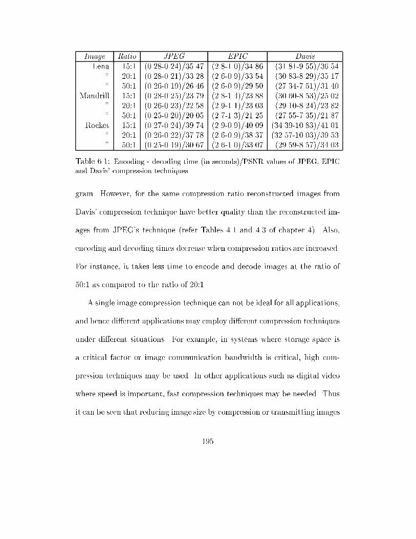
Image Ratio JPEG EPIC Davis
Lena 15:1 (0.28-0.24)/35.47 (2.8-1.0)/34.86 (31.81-9.55)/36.54
" 20:1 (0.28-0.21)/33.28 (2.6-0.9)/33.54 (30.83-8.29)/35.17
" 50:1 (0.26-0.19)/26.46 (2.6-0.9)/29.50 (27.34-7.51)/31.40
Mandrill 15:1 (0.28-0.25)/23.79 (2.8-1.4)/23.88 (30.60-8.53)/25.02
" 20:1 (0.26-0.23)/22.58 (2.9-1.1)/23.03 (29.10-8.24)/23.82
" 50:1 (0.25-0.20)/20.05 (2.7-1.3)/21.25 (27.55-7.35)/21.87
Rocket 15:1 (0.27-0.24)/39.74 (2.9-0.9)/40.09 (34.39-10.83)/41.01
" 20:1 (0.26-0.22)/37.78 (2.6-0.9)/38.37 (32.57-10.03)/39.53
" 50:1 (0.25-0.19)/30.67 (2.6-1.0)/33.07 (29.59-8.57)/34.03
Table 6.1: Encoding - decoding time (in seconds)/PSNR values of JPEG, EPIC
and Davis' compression techniques
gram. However, for the same compression ratio reconstructed images from
Davis' compression technique have better quality than the reconstructed im-
ages from JPEG's technique (refer Tables 4.1 and 4.3 of chapter 4). Also,
encoding and decoding times decrease when compression ratios are increased.
For instance, it takes less time to encode and decode images at the ratio of
50:1 as compared to the ratio of 20:1.
A single image compression technique can not be ideal for all applications,
and hence di�erent applications may employ di�erent compression techniques
under di�erent situations. For example, in systems where storage space is
a critical factor or image communication bandwidth is critical, high com-
pression techniques may be used. In other applications such as digital video
where speed is important, fast compression techniques may be needed. Thus
it can be seen that reducing image size by compression or transmitting images
195
using progressive image transmission does not provide an optimal solution
to the image transmission problem. We propose that in order to provide
an optimal solution to the image transmission problem, we need to consider
several factors such as: image storage, requested quality speci�cation, and
transmission minimisation. These factors are taken into consideration in
our proposed work to minimise the volume of transmitted image data using
multi-level browsing which is described in the next section.
6.5 A Framework for Multi-level Browsing
Currently, there is no optimal solution to the image transmission problem
as the existing systems cannot deliver exactly what the users and applica-
tions require. These systems try to reduce the volume of transmitted image
data by compression or progressive image transmission. They do not take
into consideration the concept of building a model that allows image data
to be minimised before it is delivered to users and applications. Also, the
existing browsers and network graphical user interfaces do not allow users to
specify the quality level of the image they need [LSK98]. As discussed in the
previous section, either reducing the size of image data before transmission
by compression techniques, or reducing the volume of data during the trans-
mission process by the user's early termination is not an optimal solution
196
to the image transmission problem. These two methods can only be used
to partially alleviate the problem. This is because the problem not only in-
volves the amount of stored data, the way it is transmitted and how the data
is stored, but it also depends on the users and applications' requirements.
Our investigation suggests that in �nding an optimal solution to the image
transmission problem, the entire system should be analysed because certain
approaches are suitable for some applications but may not be adequate for
others. For example, progressive image transmission may not be suitable for
non-interactive applications or for users who carry out multi-tasking most of
the time.
In dealing with the image transmission problem, we de�ne the following
factors, that a system which faces a communication bottleneck problem needs
to consider:
1. Model for storing images
2. Transmission model
3. Query model.
The way images are stored a�ects their transmission time. Ideally images
should be stored in a way that their representations take less bits and auto-
matic reconstruction at the receiver site requires less time. In systems where
197
image compression is used to reduce the size of image data, often images
are compressed by a certain image coder that compress all images using the
same technique. This results in redundancy in the �rst place since for the
same compression ratio, di�erent reconstructed images can have di�erent
quality levels (there is no known method to automatically compress images
at a speci�ed quality level, since there has not been a correct image quality
measure). The redundancy is further seen by comparing users and applica-
tions' requirements with what the system can provide. Naturally, an image
system often wants to provide images of the highest quality, however users
and applications may need images of di�erent level of quality.
The reason for having a model for storing images is because the way im-
ages are stored a�ect their transmission time. In general, how images are
stored depends on at least two important factors:
1. The nature of the services the system provides. A system which stores
images to provide a single service may store images in a way that is
di�erent from a system that stores images to provide di�erent services.
For example, a digital library may store di�erent kinds of images and
provide di�erent services such as distance education, legal services, and
normal library usage. Due to its legal services, certain images may need
to have perfect quality, however, for normal library usage, images may
198
be compressed by a lossy compression to reduce storage and transmis-
sion requirements. For a system which provides images for tourists,
images may be compressed as much as possible as long as they still
possess good quality to satisfy users.
2. The number of images the system have to store. Di�erent users and
applications may need images at di�erent quality levels. Depending
on the number of images the systems have to store, images can be
compressed at several desired and useful quality levels, or just one copy
of each is stored. In the �rst case, the system will be able to deliver
exactly what the user wants according to the quality level speci�ed by
the user. In the second case, images may need to be further compressed
to minimise their size before transmission.
In transmitting images, a single method may not be appropriate for all ap-
plications. For example, PIT may be useful in image transmission for quick
browsing. However, if the entire image is needed PIT may add extra trans-
mission time since the image has to be stored in a proper way and transmitted
in several steps that may involve extra processing time. Depending on the
requests, images may have to be either fully and sequentially transmitted,
approximately transmitted in a number of steps (e.g., using PIT), or auto-
matically transmitted according to the speci�ed quality. For example, if a
199
medical image is needed for a legal reason, then a full and sequential trans-
mission may be applied. However, if an image is needed for quick browsing,
then PIT can be useful. In certain situations, where a number of images are
needed by a non-interactive application, the images may need to be com-
pressed at a speci�ed quality level before delivery, and this requires a correct
image quality measure. PIT can not be used in this case, and transmitting
images of a higher quality level than the requested one is not an optimal
solution.
Besides the need to consider the way images are stored and transmitted,
to allow images to be requested based on quality speci�cation can facilitate
image transmission. Hence a query model should support such speci�cation.
For example, if users and applications can specify the quality level of the
image they need, then the system can deliver minimal image data to meet
the users and applications' requests. Currently, when a user or an applica-
tion requests for an image, the system cannot always deliver exactly what
the user and application need. A query model can assist the system in min-
imising the data volume before delivery. For example, if queries for images
are not speci�ed or implicit, then the system will decide what to deliver. If
queries are speci�ed or explicit, the system can minimise the data volume
before delivery.
200
To �nd an optimal solution to the image transmission problem, we pro-
pose to take in consideration the ways images are stored, transmitted, and
the way users and applications communicate with the system (i.e., image
storing, transmission and querying). We will describe di�erent models for
storing images, discuss how image data should be minimised before trans-
mission, and classify image quality into a number of levels to allow better
image queries (i.e., to allow better communication between the system and
the users/applications). First, we show that image quality can be classi-
�ed into a limited number of levels, then de�ne the four most commonly
used quality levels and discuss three possible models by which images can
be stored to support the notion of multi-level browsing. We analyse the im-
provement in transmission time if multi-level browsers are used. Statistical
information about transmission rates on the Internet is collected and the
average value is used in our examples to show the usefulness of multi-level
browsing for Internet applications.
6.5.1 Image Quality Classi�cation
When images are compressed, they can be compressed at any ratio r 2 R,
however only a certain number of quality levels K, K 2 N, of the recon-
structed images at certain compression ratios are useful and distinguishable
201
by human eyes. This has lead to the need to classify image quality into a
number of useful levels which are described in this section. In general, the
quality of an image can be divided into K di�erent levels (K 2 N). Level 1
corresponds to the perfect quality level that indicates that the modi�ed im-
age has the same quality as the original image (i.e., the image is compressed
by a lossless compression algorithm or not compressed at all and hence no
information is lost). Level 2 and higher levels indicate the quality level of
the modi�ed image with increasing amount of lost information (i.e., if an
image is compressed by a lossy compression with a higher compression ratio
then more quality is lost). Progressively the quality of the compressed image
degrades as the value of K increases.
We can see that the number of useful image quality levels K is a limited
integer, even though a lossy compression algorithm can compress images at
any compression ratio r :1, where r 2 R. This is because in general for two
ratios r1 and r2 if jr1 � r2 j is small (e.g., < 0.5), the two compressed images
at compression ratio r1 and r2 can be indistinguishable by human eyes. Also,
for some rm , m 2 N, compressed images with compression ratios greater than
rm is not useful, because the reconstructed image will be totally distorted,
or so distorted that it cannot be useful.
202
Although, image quality can be classi�ed into a number of levels, in gen-
eral a small number of levels of quality would be su�cient and satisfy most
users' requirements. Hence we de�ne four levels of quality in our proposed
multi-level browsing model, although in principle the model does not impose
any restriction on the number of image quality levels. The selected four lev-
els are labelled as perfect , good , acceptable and blurred with the following
meaning.
perfect : This means that images are compressed by a lossless compres-
sion technique.
good : Indicates the quality of the reconstructed image is indistinguish-
able from the original with respect to human eyes.
acceptable : Means the quality of the reconstructed image is still good
for temporary viewing but not for applications where quality is critical. The
possible use of images with this quality level is users' browsing through an
image repository like teleshopping.
blurred : Objects can still be identi�ed but users can tell the the image
has a poor quality. The loss is noticeable to human eyes. This quality level
can be used for quick browsing.
203
6.5.2 Models for Storing Digital Images
Currently distributed image databases and systems such as digital libraries,
telebrowsing systems store digital images at the best possible quality in order
to meet di�erent requirements (this is because the systems can not predict
what level of quality of requested images is needed by di�erent users and
applications). In most of the existing image repositories, images are stored
in a compressed form, the original image is usually compressed at a certain
compression ratio and the compressed image is stored, even in systems where
the number of images is small. This has naturally lead to a question that if
a site has a small number of images and a high number of users accessing
the image data, then is there a way that images can be stored to minimise
transmission. A possible solution is to store images as a compressed �le
and employ PIT. However, this solution requires users to continuously pay
attention during the transmission process. We propose that in order to facil-
itate image transmission, images need to be stored according to the number
of images the system has, the services the system provides, and the users'
requirements. We propose the following three models for storing images:
1. Model 1: In this model, images are compressed at four di�erent quality
levels perfect , good , acceptable, and blurred . Four copies of an image
that correspond to the four quality levels are stored. This model is more
204
appropriate for applications which have a small number of images and
the site (where the images are stored) is frequently accessed by a high
number of users. For example, a small image repository that stores the
latest discovery of things such as sightings of UFOs can use this model.
2. Model 2: In this model, images are originally compressed by a lossless
compression technique with perfect quality. Certain applications such
as medical image databases need to store images of perfect quality for
some reason (e.g., for legal reason). However users may require images
at lower quality levels.
3. Model 3: In this model, images are originally compressed by a com-
pression techniques at good quality level, e.g., using JPEG with com-
pression ratio of 15 to 1. Certain applications such as online tourism
information may only need to provide images at this quality level.
6.6 Multi-level Browsing
The main task of existing browsers and network graphic user interfaces (e.g.,
Netscape) is to provide an e�ective and e�cient interface between users and
the information repository. Usually the browser is supposed to provide a user-
friendly interface and deliver the data provided by the repository. In order
205
to minimise the volume of image data before transmission, images need to be
stored in a proper way, the browser needs to allow users to specify what they
want, and the whole system needs to work together to dynamically employ
the appropriate image compression techniques We propose the concept of
multi-level browsing to obtain an optimal solution to the image transmission
problem which is based on the following principles:
1. Di�erent users and applications may require images at di�erent quality
levels. The quality of the delivered images should be as close as possible
to the users' requested level.
2. Each compression method has its advantages and disadvantages, hence
they should be e�ectively used in di�erent situations to best facilitate
image transmission.
3. A browser or network graphic user interface should deliver minimum
data as requested by users and applications. To be able to do this,
the browser needs to allow users and applications to specify the quality
level of the image they request.
The general structure of a multi-level browser is shown in Figure 6.1. A
multi-level browser allows users to specify the level of quality for the images
they need. If the required image is stored using model 1, then it is fetched and
206
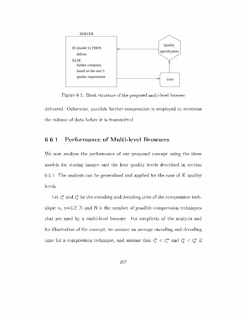
User
SERVER
ELSE
specificationIF (model 1) THEN
further compress
based on the user’s
quality requirement
deliver
Quality
Figure 6.1: Block structure of the proposed multi-level browser
delivered. Otherwise, possible further compression is employed to minimise
the volume of data before it is transmitted.
6.6.1 Performance of Multi-level Browsers
We now analyse the performance of our proposed concept using the three
models for storing images and the four quality levels described in section
6.5.1. The analysis can be generalised and applied for the case of K quality
levels.
Let tnc and tnd be the encoding and decoding time of the compression tech-
nique n, n=1,2..N and N is the number of possible compression techniques
that are used by a multi-level browser. For simplicity of the analysis and
for illustration of the concept, we assume an average encoding and decoding
time for a compression technique, and assume that tnc < tmc and tnd < tmd if
207
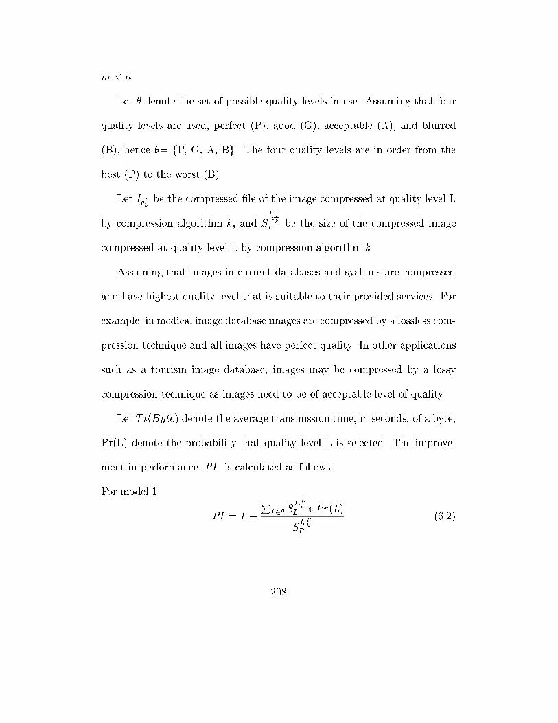
m < n.
Let � denote the set of possible quality levels in use. Assuming that four
quality levels are used, perfect (P), good (G), acceptable (A), and blurred
(B), hence �= fP, G, A, Bg. The four quality levels are in order from the
best (P) to the worst (B).
Let IcLk
be the compressed �le of the image compressed at quality level L
by compression algorithm k , and S
IcL
k
L be the size of the compressed image
compressed at quality level L by compression algorithm k .
Assuming that images in current databases and systems are compressed
and have highest quality level that is suitable to their provided services. For
example, in medical image database images are compressed by a lossless com-
pression technique and all images have perfect quality. In other applications
such as a tourism image database, images may be compressed by a lossy
compression technique as images need to be of acceptable level of quality.
Let T t(Byte) denote the average transmission time, in seconds, of a byte,
Pr(L) denote the probability that quality level L is selected. The improve-
ment in performance, PI , is calculated as follows:
For model 1:
PI = 1 �P
L2� SIcLk
L � Pr(L)SIcPk
P
(6.2)
208
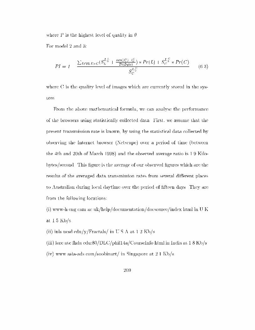
where P is the highest level of quality in �.
For model 2 and 3:
PI = 1 �P
L2�&L>C (SIcLk
L +min(tnc )+t
Cd
Tt(Byte)) � Pr(L) + S
IcCk
C � Pr(C )
SIcCk
C
(6.3)
where C is the quality level of images which are currently stored in the sys-
tem.
From the above mathematical formula, we can analyse the performance
of the browsers using statistically collected data. First, we assume that the
present transmission rate is known, by using the statistical data collected by
observing the Internet browser (Netscape) over a period of time (between
the 4th and 20th of March 1998) and the observed average ratio is 1.9 Kilo-
bytes/second. This �gure is the average of our observed �gures which are the
results of the averaged data transmission rates from several di�erent places
to Australian during local daytime over the period of �fteen days. They are
from the following locations:
(i) www-h.eng.cam.ac.uk/help/documentation/docsource/index.html in U.K
at 1.5 Kb/s.
(ii) inls.ucsd.edu/y/Fractals/ in U.S.A at 1.2 Kb/s.
(iii) lore.atc.fhda.edu:80/DLC/phil14a/CourseInfo.html in India at 1.8 Kb/s.
(iv) www.asia-ads.com/soobinart/ in Singapore at 2.1 Kb/s.
209
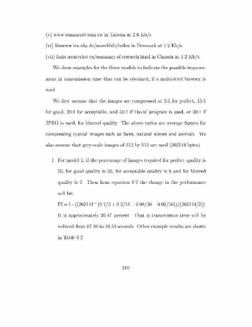
(v) www.commerce.com.tw in Taiwan at 2.6 Kb/s.
(vi) liinwww.ira.uka.de/searchbib/index in Denmark at 1.2 Kb/s.
(vii) links.uwaterloo.ca/summary.of.research.html in Canada at 1.2 Kb/s.
We show examples for the three models to indicate the possible improve-
ment in transmission time that can be obtained, if a multi-level browser is
used.
We �rst assume that the images are compressed at 2:1 for perfect, 15:1
for good, 20:1 for acceptable, and 50:1 if Davis' program is used, or 30:1 if
JPEG is used, for blurred quality. The above ratios are average �gures for
compressing typical images such as faces, natural scenes and animals. We
also assume that grey-scale images of 512 by 512 are used (262144 bytes).
1. For model 1, if the percentage of images required for perfect quality is
70, for good quality is 20, for acceptable quality is 8 and for blurred
quality is 2. Then from equation 6.2 the change in the performance
will be:
PI = 1 - ((262144 * (0.7/2 + 0.2/15 + 0.08/20 + 0.02/50))/(262144/2)).
It is approximately 26.47 percent. That is transmission time will be
reduced from 67.36 to 49.53 seconds. Other example results are shown
in Table 6.2.
210
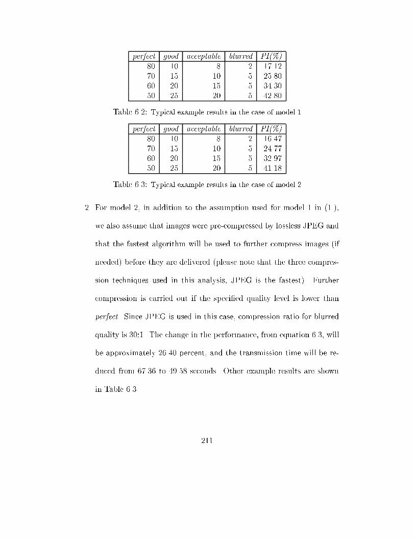
perfect good acceptable blurred PI(%)
80 10 8 2 17.12
70 15 10 5 25.80
60 20 15 5 34.30
50 25 20 5 42.80
Table 6.2: Typical example results in the case of model 1
perfect good acceptable blurred PI(%)
80 10 8 2 16.47
70 15 10 5 24.77
60 20 15 5 32.97
50 25 20 5 41.18
Table 6.3: Typical example results in the case of model 2
2. For model 2, in addition to the assumption used for model 1 in (1.),
we also assume that images were pre-compressed by lossless JPEG and
that the fastest algorithm will be used to further compress images (if
needed) before they are delivered (please note that the three compres-
sion techniques used in this analysis, JPEG is the fastest). Further
compression is carried out if the speci�ed quality level is lower than
perfect . Since JPEG is used in this case, compression ratio for blurred
quality is 30:1. The change in the performance, from equation 6.3, will
be approximately 26.40 percent, and the transmission time will be re-
duced from 67.36 to 49.58 seconds. Other example results are shown
in Table 6.3.
211
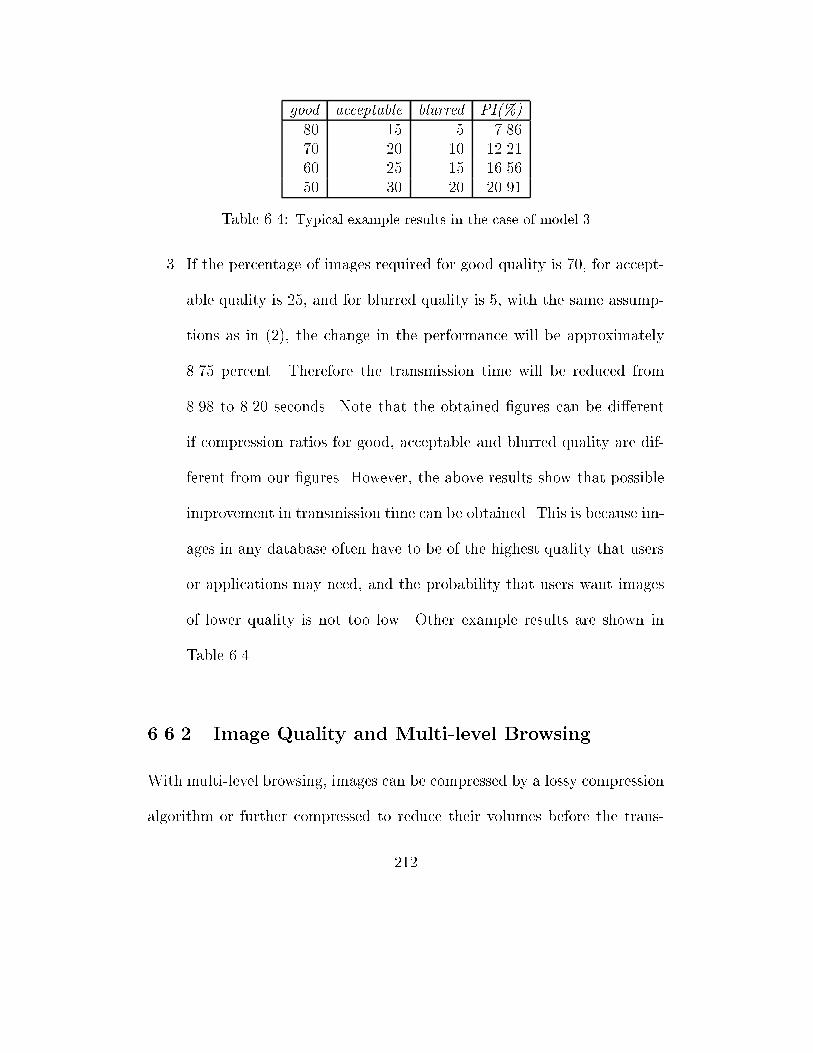
good acceptable blurred PI(%)
80 15 5 7.86
70 20 10 12.21
60 25 15 16.56
50 30 20 20.91
Table 6.4: Typical example results in the case of model 3
3. If the percentage of images required for good quality is 70, for accept-
able quality is 25, and for blurred quality is 5, with the same assump-
tions as in (2), the change in the performance will be approximately
8.75 percent. Therefore the transmission time will be reduced from
8.98 to 8.20 seconds. Note that the obtained �gures can be di�erent
if compression ratios for good, acceptable and blurred quality are dif-
ferent from our �gures. However, the above results show that possible
improvement in transmission time can be obtained. This is because im-
ages in any database often have to be of the highest quality that users
or applications may need, and the probability that users want images
of lower quality is not too low. Other example results are shown in
Table 6.4.
6.6.2 Image Quality and Multi-level Browsing
With multi-level browsing, images can be compressed by a lossy compression
algorithm or further compressed to reduce their volumes before the trans-
212
mission, also users can specify the quality of their requested images [LSK98].
However, correctly measuring the quality of images is important. The subjec-
tive methods [CCI90a, TPO96], are evaluated by test persons and hence they
are not suitable for use in multi-level browsers or network graphic user in-
terfaces. The RMSE and its variants do not coincide well with human visual
perception as demonstrated in chapter 4 and in [Wat93, LSS+98]. There-
fore they can not be used either. The colour-based technique which is quite
popular, however, as shown in chapter 4, also su�ers the same problem as
the RMSE and hence can not be used to support the concept of multi-level
browsing.
The concept of multi-level browsing requires that the system be able to
allow users and applications to specify the levels of quality of their requested
images and also that images may need to be compressed by lossy compression
algorithms. Hence the system needs to employ a good quality measure. Our
proposed image quality measure, called IQME [LSS+98], is chosen, since it
not only works better than the RMSE but also coincides well with human
visual perception. From the results in chapter 4, we can see that it can be
used to specify image quality levels while RMSE is not reliable. In summary,
our proposed image quality measure enables multi-level browsing. It pro-
vides a viable model for deriving a solution to the communication bottleneck
213

problem that we posed at the beginning of this chapter.
6.7 Conclusion
The increasing number of digital image applications and growing rate of users
accessing digital image systems and databases via networks makes the com-
munication bottleneck problem a signi�cant challenge. Research in image
compression will continue to look for better compression techniques so that
the volume of image data can be reduced and hence the transmission time.
To minimise the volume of image data to be transmitted across networks,
the main principle is to deliver exactly the amount of data the users and
applications need. In order to follow this principle, the entire system should
be considered in terms of the requirements of users and applications want,
images are stored and transmitted. Users and applications should not be
shackled by the transmission process and allowed to specify what they want.
In �nding a model for storing images, the consideration of the services that
the system provides should be taken into account. Reducing the size of im-
ages as much as possible by a single compression technique is not always
ideal when communication is a bottleneck or transmission time is a problem.
This chapter showed the disadvantages of systems that use either lossy
compression techniques or PIT methods for reducing transmission time of
214
image data. It then proposed a new methodology for minimising the image
data volume before transmission and consequently reducing the transmission
time. Di�erent models for storing images were described. The classi�cation
of image quality into a �nite number of levels was also presented and the
four most commonly used image quality levels were proposed. This work
is enhanced by our proposed image quality measure and image compression
methods described in chapters 4 and 5. Since our proposed image quality
measure coincides with human visual perception better than the other most
commonly used techniques, it allows images to be compressed at any desired
quality level more accurately and makes image quality speci�cation by users
and applications possible. The use of our image quality measure in our image
coders provides higher compression and hence allows the size of images to be
further reduced before storing or transmitting.
Finally, the concept of multi-level browsing integrates well with the ad-
vancement of network technology, image transmission and image compression
developments. It not only makes a signi�cant contribution to solve the image
transmission problem but also suggests necessary changes to current systems
so that they can adapt well to the new age of multimedia information.
215

Chapter 7
Conclusion
Digital image applications have become increasingly important. The use-
fulness of digital images are well recognised. However, it is also well-known
that there are a number of problems associated with the use of digital images
such as high storage requirements, transmission costs, and the evaluation of
the quality of modi�ed images. The need for an accurate image quality mea-
sure is especially urgent due to its use in many image applications such as
in testing video systems, in improving image coding, and in automatically
coding and decoding images before storage and transmission. This chapter
summarises the research work covered in this thesis and is organised into
three sections. First, it states the main contributions of the thesis. Then it
presents the summary of each contribution and possible future research in
216
each section.
This thesis has made three main contributions:
1. The proposal of a class of objective image quality measures,
2. The design and development of two perception based image compres-
sion algorithms, and
3. A novel framework for e�cient image transmission.
In the following, we elaborate our contributions and possible future research.
7.1 A Class of Objective Quality Measures
The e�ectiveness of the proposed class of image quality measures results
from the normalisation of the modi�ed image and its original, the choice
of unit to measure the errors, the consideration of local and global e�ects
of noise in calculating errors, and the consideration of the stronger e�ects
of concentrated noise over random noise. The proposed work exhibits the
following desirable properties of a good measure.
� It is a class of objective measures.
� It makes no assumption about noise and viewing conditions.
217
� It demonstrates the very desirable property that an image quality mea-
sure is expected to have. Namely, it parallels with human perception.
The validity of the proposed class of image quality measures have been eval-
uated by two di�erent methods.
� First, an implementation of the class was tested using various test im-
ages, di�erent compression programs including buggy ones, and di�er-
ent ways to generate various types and levels of noise. To evaluate the
performance of the proposed work in comparison to the two most popu-
lar measures, the RMSE (and PSNR) and the colour-based techniques,
we applied the same test data to our measure and the other two meth-
ods. We found that our measure is able to capture di�erent possible
noise and performs more consistently than the other two methods.
� Second, our proposed class of measures is objective and can be e�-
ciently employed to �ne-tune image compression. Therefore, we have
employed it to improve the quantisation and best basis function selec-
tion to achieve high compression. The results from our coders demon-
strated that the measure is a valuable tool for image coding. In ad-
dition, its application in multi-level browsing to provide an optimal
solution to the image transmission problem has further con�rmed its
validity and usefulness.
218
An implementation from the proposed class of image quality measures has
con�rmed the usefulness of the proposed class of measures. However, there
are a number of attractive things that have not been investigated and will
be part of our future research focuses. These include
� The employment of di�erent existing techniques to calculate the errors
that occur in the local units.
� The investigation of the e�ect of variable units. That is to allow the
measurable units to be of di�erent shapes and sizes.
� The search for a measure based on this class that a mathematical proof
of its validity over the MSE can be found. This is motivated by the
argument that since the proposed class uses units larger than individual
pixels, it may be possible to �nd an extension of the MSE that belongs
to this class.
7.2 Perception Based Image Compression
Currently, there are two important image coding approaches - the fractal and
wavelet image compression paradigms - that focus on the search for better
basis functions to approximate signals. Our study of these approaches and
other compression methods, such as the traditional block transform coding
219
and vector quantisation based coding, has shown that the two main factors
that a�ect the coding gain is the quantisation and selection of the best bases
for representing images. In addition, the performance of these two factors
depends on a mathematical distortion measure. This thesis has examined
the hypothesis that higher image compression is possible if a good distor-
tion measure is used in developing image compression systems. To test this
thesis, we �rst generalised the two main image compression methodologies,
that search for a �nite set of maps which require minimum bits to repre-
sent an image, to show that image compression in general depends on the
quantisation and selection of the best bases. We then showed that in both
quantisation and selection of the best basis process, an objective and ac-
curate image quality evaluation plays an important role. This implies that
higher image compression can be obtained with the employment of a good
image quality measure in the quantisation process or the best basis selection
algorithm. Second, we mathematically demonstrated that the hypothesis is
correct. Third, we developed two image compression algorithms to experi-
mentally test the hypothesis. The �rst algorithm is based on the subband
decomposition to simulate the fractal block coding method with the support
of our proposed image quality measure in the quantisation process. Our
coding scheme has signi�cantly reduced the range-domain matching search
220
complexity that is incurred in fractal block based image coders, and with the
support of our quality measure better gain in the quality of the reconstructed
image is obtained. The second algorithm is based on wavelet packets. Our
image quality measure is used to allow better selection of wavelet packet
bases and hence better compression. The experimental results from our two
image coders demonstrated the success of the two proposed compression al-
gorithms. The coders not only perform better when our quality measure is
used instead of the classic mean-square-error, but also outperform the re-
cently reported compression coders that are based on similar approaches.
The success of our two image compression algorithms based on our image
quality evaluation method proved the validity of our proposed image quality
measures and showed the success of our investigation in using image quality
measure to improve image coding. Our mathematical analysis and coding
algorithms can serve as a platform for testing new distortion measures. A
new distortion measure can be used in either coding algorithm. If higher
compression is obtained then there is a possibility that the new measure per-
forms better than the existing ones. This minimises the costs of testing a
new image quality measure and can hence be an e�ective tool for devising
new image quality measures. It suggests a new approach for testing new
image quality methods. The success of applying our quality measure to im-
221
prove quantisation also suggests that our image quality evaluation method
can be employed in uniform and non-uniform vector quantisation to reduce
quantisation errors. Our future research work will include:
� Using our compression algorithms as a platform to test other existing
and possible new quality measures in terms of compression gain (i.e.,
compression gain is used as the criterion for the validity of a measure).
� Employing our image quality evaluation method to �nd out the level of
compression improvement when uniform and non-uniform vector quan-
tisation and space-frequency quantisation is applied in image coders.
(the unit used in our proposed measure can vary, also it is possible to
group coe�cients before quantisation, therefore our measures can be
employed to improve these quantisation techniques).
7.3 Multi-level Browsing for E�cient Image
Transmission
In looking for the solution to the image transmission problem across networks
in the age of multimedia information, we believe that we need to consider sev-
eral factors and the relationship between these factors. These factors include
image storing methodology, the provided services, users and applications' re-
222
quirements, image transmission methodology, and the future development of
network technologies. This is because in order to provide an optimal solution
to the image transmission problem, we need not only to provide satisfaction
to all users and applications but also to consider the evolution of the sys-
tem. We proposed the novel concept of multiple-level browsing to provide
an optimal solution to the image transmission problem. We �rst considered
the potential tra�c increase. We then proposed models for storing images
and the classi�cation of image quality. Lastly we proposed a framework for
constructing a system to allow image compression methods and quality levels
to be selected dynamically. The overall volume of image data will then be
minimised before transmission. The proposed multi-level browsing is also
completely compatible with continuing advancements in network technology,
image transmission and image compression techniques. The framework is
independent from the system conditions such as system workload, and from
existing methods for reducing the size of the stored images. The only fac-
tor that can a�ects the analysis is the probability of required quality levels
from users and applications. This suggests a future investigation on how the
distribution of users and applications' requirements a�ect the analysis.
223
References
[ABMD92] M. Antonini, M. Barlaud, P. Mathieu, and I. Daubechies. Image
coding using wavelet transform. IEEE Transactions on Image
Processing, 1(2):205{220, 1992.
[AFMN93] V. R. Algazi, G. E. Ford, M. Mow, and A. Najmi. Design of
subband coders for high quality based on perceptual criteria.
In Proceedings of SPIE Application of Digital Image Processing
XVI, pages 40{49, 1993.
[AS87] E. H. Adelson and E. P. Simoncelli. Orthogonal pyramid trans-
forms for image coding. In Proceedings of SPIE Visual Commu-
nication and Image Processing, pages 50{58, 1987.
[AS93] J. L. Arrowood and M. J. T. Smith. Exact reconstruction anal-
ysis/synthesis �lter banks with time-varying �lters. In Proceed-
224
ings of IEEE International Conference on Acoustics, Speech and
Signal Processing, pages 233{236, 1993.
[ASB96] M. Annamalai, A. Sundaram, and B. Bhargava. A color based
technique for measuring visible loss in image data communi-
cation. In Proceedings of The International Conference on
Database and Expert Systems Applications (DEXA), pages 39{
48, 1996.
[AWW92] P. Auscher, G. Weiss, and M. V. Wickerhauser. Local sine
and cosine bases of Coifman and Meyer and the construction
of smooth wavelets. In C. K. Chui, editor, Wavelets: A Tutorial
in Theory and Applications, pages 15{51. Academic Press, 1992.
[BA95] B. Bhargava and M. Annamalai. Communication costs in digital
library database. In Proceedings of International Conference on
Database and Expert Systems Applications (DEXA), pages 1{13,
1995.
[Bar74] G. De Barra. Introduction to measure theory. Van Nostrand
Reinhold, New York, 1974.
[Bar90] P. G. J. Barten. Evaluation of subjective image quality with the
square-root integral method. J.O.S.A A, 7:2024{2031, 1990.
225
[BBA95] R. Balasubramanian, C. A. Bouman, and J. P. Allebach. Se-
quential scalar quantisation of vector: An analysis. IEEE Trans-
actions on Image Processing, 4(9):1282{1295, 1995.
[BCR91] G. Beylkin, R. R. Coifman, and V. Rokhlin. Fast wavelet trans-
forms and numerical algorithms. Comm. in Pure and Appl.
Math., 44:141{183, 1991.
[BE95] B. Bani-Eqbal. Enhancing the speed of fractal image compres-
sion. Optical Engineering, 34(6):1705{1710, 1995.
[Ber93] G. Bernd. What's wrong with mean-squared error? In A. B.
Walson, editor, Digital Images and Human Vision, pages 207{
220. MIT Press, 1993.
[BH93] M. F. Barnsley and L. P. Hurd. Fractal image compression. AK
Peters Ltd., Wellesley, Massachusetts, 1993.
[BJ88] M. F. Barnsley and A. Jacquin. Application of recurrent itera-
tive function systems to images. In Proceedings of SPIE Visual
Communications and Image Processing, pages 122{131, 1988.
[BMK93] Z. Barahav, D. Malah, and E. Karnin. Hierarchical interpreta-
tion of fractal image coding and its application to fast decoding.
226
In Proceedings of the International Conference on Digital Signal
Processing, pages 190{195, Nicosia, Cyprus, 1993.
[Bog95] A. Bogdan. The fractal pyramid with application to image cod-
ing. In Proceedings of IEEE International Conference on Acous-
tics, Speech and Signal Processing, pages 2595{2598, 1995.
[Bon96] R. Bonneau. Multiresolution transform and its application to
image coding. In Rashid Ansari and Mark J. Smith, editors,
Visual Communications and Image Processing 96, SPIE Pro-
ceedings, pages 560{567, 1996.
[BS88] M. F. Barnsley and A. D. Sloan. A better way to compress
images. Byte Magazine, 13:215{223, Jan 1988.
[BSG+93] M. Barlaud, P. Sole, T. Gaidon, M. Antonini, and P. Mathieu.
Elliptical codebook for lattice vector quantisation. In Proceed-
ings of IEEE International Conference on Acoustics, Speech and
Signal Processing, pages 590{593, 1993.
[BSG+94] M. Barlaud, P. Sole, T. Gaidon, M. Antonini, and P. Math-
ieu. Pyramidal lattice vector quantisation for multiscale image
coding. IEEE Transaction on Image Processing, 3(4):367{381,
1994.
227
[BWW96] F. Bock, H. Walter, and M. Wilde. New distortion measure for
the assessment of decoded images adapted to human perception.
In Technical Report, Computer Based Learning Unit, University
of Leeds, 1996.
[CAS+92] C. K. Cheong, K. Aizawa, T. Saito, , and M. Hatori. Subband
image coding with biorthogonal waveletes. IEICE Transactions
on Fundamentals, E75-A:871{881, 1992.
[CCI90a] CCIR. Recommendation 500: Method for subjective assessment
of the quality of television pictures. Recommendations of the
CCIR, 11(1), 1990.
[CCI90b] CCIR. Recommendation 710: Subjective assessment methods
for image quality in high-de�nition television. Recommendations
of the CCIR, 11(1), 1990.
[CDF92] A. Cohen, I. Daubechies, and J. Feauveau. Bi-orthogonal bases
of compactly supported wavelets. Comm. Pure and Appl. Math.,
45:485{500, 1992.
[CGG92] W. Y. Chan, S. Gupta, and A. Gersho. Enhanced multistage
vector quantisation for image coding. IEEE Transactions on
Communications, 40(11):1693{1697, 1992.
228
[CGV96] P. C. Cosman, R.M. Gray, and M. Vetterli. Vector quantization
of image subbands: A review. IEEE Transactions on Image
Processing, 5(2):202{225, 1996.
[Chu92] C. K. Chui. Wavelets: A Tutorial in Theory and Applications.
Wavelet Analysis and its Applications. Academic Press, Inc.,
1992.
[CK92] N. T. Cheng and N. G. Kingsbury. The erpc: An e�cient error
resilient technique for encoding positional information or sparse
data. IEEE Transactions on communications, 40(1):140{148,
1992.
[CLG89] P. A. Chou, T. Lookabaugh, and R. M. Gray. Entropy-
constrained vector quantisation. IEEE Transactions on Acous-
tics, Speech and Signal Processing, 37(1):31{42, 1989.
[CMG85] P. C. Chang, J. May, and R. M. Gray. Hierarchical vector quan-
tisers with table-lookup encoders. In Proceedings of IEEE In-
ternational Conference on Communications, pages 1452{1455,
1985.
[CMQW92] R. R. Coifman, Y. Meyer, S. Quake, and M. V. Wickerhauser.
Signal processing and compression with wave packets. In Pro-
229
ceedings of the International Conference on Wavelet Applica-
tions, pages 77{93, 1992.
[Con90] J. B. Conway. A course in functional analysis. Springer-Verlag,
New York, 1990.
[CPP+91] P. C Cosman, K. O. Perlmutter, S. M. Perlmutter, R. A. Olshen,
and R. M. Gray. Training sequence size and vector quantiser
performance. In Proceedings of the 25th Asilomar Conference
on Signals, systems and Computers, pages 434{438, 1991.
[CR94] L. H. Croft and J. A. Robinson. Subband image coding using
watershed and watercourse lines of the wavelet transform. IEEE
Transactions on Image Processing, 3(6):759{772, 1994.
[CS88] J. H. Conway and N. J. A. Sloane. Sphere packing, Lattice and
Groups. Springer-Verlag, 1988.
[CvdBL96] D. M. Costantini and C. J. van den Branden Lambrecht. Mo-
tion rendition quality metric for MPEG coded video. In IEEE
International Conference on Image Processing, pages 889{892,
1996.
230

[CW90] R. A. Cohen and J. W. Woods. Sliding block entropy coding
of images. In Proceedings of IEEE International Conference on
Acoustics, Speech and Signal Processing, pages 1731{1734, 1990.
[CW92] R. R. Coifman and M. V. Wickerhauser. Entropy-based algo-
rithms for best basis selection. IEEE Transactions on Informa-
tion Theory, 38(2):713{718, 1992.
[Dal92] S. Daly. The visible di�erences predictor: An algorithm for
the assessment of image �delity. In Proceedings of the SPIE,
Human Vision, Visual Processing, and Digital Display II, pages
2{14, 1992.
[Dau88] I. Daubechies. Orthonormal bases of compactly supported
wavelets. Comm. in Pure and Appl. Math., XLI(41):909{996,
1988.
[Dau89] I. Daubechies. Orthonormal bases of wavelets with �nite
support-connection with discrete �lters. In J. M. Combes,
A. Grossman, and Ph. Tchamitchian, editors, Wavelets, Time-
Frequency Methods and Phase Space, pages 38{66. Springer-
Verlag, Berlin, 1989. Proceedings of International Colloquium
on Wavelets and Applications, Marseille, France, 1989.
231
[Dau92] I. Daubechies. Ten Lectures on Wavelets. Number 61 in CBMS-
NSF Series in Applied Mathematics. SIAM, Philadelphia, 1992.
[Dau93a] I. Daubechies. Orthonormal bases of compactly supported
wavelets: II. variations on a theme. SIAM J. Math. Anal.,
24:499{519, 1993.
[Dau93b] I. Daubechies. Wavelet transforms and orthonormal wavelet
bases. In Ingrid Daubechies, editor, Di�erent Perspectives on
Wavelets, volume 47 of Proceedings of Symposia in Applied
Mathematics, pages 1{33. American Math. Soc., Providence, RI,
1993.
[Dav95] G. Davis. Self-quantized wavelet subtrees: A wavelet-based the-
ory of fractal image compression. In Harold H. Szu, editor,
Wavelet Applications II, SPIE Proceedings, pages 141{152, Or-
landa, FL, USA, 1995.
[Dav96] G. Davis. Image compression via adaptive self-quantization of
wavelet subtrees. In Proceedings of IEEE International Confer-
ence on Acoustics, Speech and Signal Processing, pages 2359{
2362, 1996.
232
[DG85] M. O. Dunham and R. M. Gray. An algorithm for the design of
labeled transition �nite-state vector quantisation. IEEE Trans-
actions on Communications, 33(1):83{89, 1985.
[DJL92] R. DeVore, B. Jawerth, and B. J. Lucier. Image compression
through wavelet transform coding. IEEE Transactions on In-
formation Theory, 38(2):719{746, 1992.
[DM79] E.J. Delp and O.R. Mitchell. Image compression using block
truncation coding. IEEE Transactions on Communications,
27(9):1335{1342, 1979.
[DPTI96] J.F. David, M. Peter, P. Thomas, and M. Ivan. Establishing
perceptual criteria on image quality in diagnostic telepathology.
In IEEE International Conference on Image Processing, pages
873{876, 1996.
[Dud92] F. Dudbridge. Image Approximation by Self A�ne Fractals.
PhD thesis, Imperial College, London, England, 1992.
[EF95] A. M. Eskicioglu and P. S. Fisher. Image quality measures
and their performance. IEEE Transactions on communications,
43(12):2959{2965, 1995.
233
[EG77] D. Esteban and C. Galand. Applications of quadrature mirror
�lters to split band voice coding schemes. In Proceedings of
IEEE International Conference on Acoustics, Speech and Signal
Processing, pages 191{195, 1977.
[Fis95] Y. Fisher, editor. Fractal Image Compression: Theory and Ap-
plication to Digital Images. Springer-Verlag, New York, 1995.
[FM92] J. Froment and S. Mallat. Second generation compact image
coding. In C. K. Chui, editor, Wavelets: A Tutorial in Theory
and Applications, pages 655{678. Academic Press, 1992.
[FMW91] T. R. Fisher, M. W. Marcellin, and M. Wang. Trellis-coded
vector quantisation. IEEE Transactions on Information Theory,
37(6):1551{1566, 1991.
[Ger79] A. Gersho. Asymptotically optimal block quantisation. IEEE
Transactions on Information Theory, 25(4):373{380, 1979.
[GG92] R. Gersho and R. M. Gray. Vector quantisation and signal com-
pression. Kluwer Academic Publishers, Boston, 1992.
[GV90] D. D. Giusto and G. Vernazza. Colour image coding by an
advanced vector quantiser. In Proceedings of IEEE International
234
Conference on Acoustics, Speech and Signal Processing, pages
2265{2268, 1990.
[GW91] M. Goldberg and L. Wang. Comparative performance of pyra-
mid data structures for progressive image transmission. IEEE
Transactions on Communications, 39(4):540{547, 1991.
[HG88] Y. S. Ho and A. Gersho. Variable-rate multi-stage vector quan-
tisation for image coding. In Proceedings of IEEE International
Conference on Acoustics, Speech and Signal Processing, pages
1156{1159, 1988.
[HLC91] C. H. Hsieh, P. C. Lu, and J. C. Chang. A fast codebook genera-
tion algorithm for vector quantisation of images. In Proceedings
of the IEEE International Symposium on Circuits and Systems,
pages 288{291, 1991.
[HMS96] R. Hamzaoui, M. M�uller, and D. Saupe. VQ-enhanced frac-
tal image compression. In Proceedings of IEEE International
Conference on Acoustics, Speech and Signal Processing, pages
153{156, Lausanne, Switzerland, 1996.
235
[HN94] H. Hamada and S. Namba. A study on object picture quality
scales for picture digitally encoded for broadcast. IEICE Trans-
actions on Communications, E77-B(12):1480{1487, 1994.
[HT86] W. D. Hofmann and D. E. Troxel. Making progressive trans-
mission adaptive. IEEE Transactions on Image Processing,
34(8):806{813, 1986.
[Huf77] D. A. Hu�man. A method for the construction of minimum
redundancy codes. In Proceedings of the IRE, pages 1098{1101,
1977.
[Hut81] J. E. Hutchinson. Fractal and self-similarity. Indiana University
Mathematics Journal, 3(5):713{747, 1981.
[HW85] H. M. Hang and J. W. Woods. Predictive vector quantisation of
images. IEEE Transactions on Communications, 33(11):1208{
1219, 1985.
[Jac90] A. E. Jacquin. A novel fractal block-coding technique for digital
images. In Proceedings of IEEE International Conference on
Acoustics, Speech and Signal Processing, pages 2225{2228, 1990.
236
[Jac92] A. E. Jacquin. Image coding based on a fractal theory of iter-
ated contractive image transformations. IEEE Transactions on
Image Processing, 1(1):18{30, 1992.
[JG89] D. G. Jeong and J. D. Gibson. Lattice vector quantisation for
image coding. In Proceedings of IEEE International Conference
on Acoustics, Speech and Signal Processing, pages 1743{1746,
1989.
[JJ82] B. H. Juang and A. H. Gray Jr. Multiple stage vector quanti-
sation for speech coding. In Proceedings of IEEE International
Conference on Acoustics, Speech and Signal Processing, pages
597{600, 1982.
[JJS93] N. Jayant, J. Johnston, and R. Safranek. Signal compression
based on models of human perception. Proceedings of IEEE,
81(10):1385{1422, 1993.
[JN84] N. S. Jayant and P. Noll. Digital Coding of Waveforms. Prentice-
Hall, Inc., Englewood Cli�s, NJ, 1984.
[JSM92] O. Johnsen, O. V. Shentov, and S. K. Mitra. A technique for the
e�cient coding of the upper bands in subband coding of images.
237
In Proceedings of IEEE International Conference on Acoustics,
Speech and Signal Processing, pages 2095{2100, 1992.
[KGMA95] K. Kotani, Q. Gan, M. Miyahara, and V.R. Algazi. Objective
picture quality scale for colour image coding. In IEEE Pro-
ceedings of International Conference on Image Processing, pages
133{136, 1995.
[Kim88] T. Kim. New �nite-state vector quantisers for images. In IEEE
International Conference on Acoustics, Speech and Signal Pro-
cessing, pages 1180{1183, 1988.
[KK95] S. A. Karunasekera and N. J. Kingsbury. A distortion measure
for blocking artifacts in image based on human visual sensitive.
IEEE Transactions on Image Processing, 4(6):957{971, 1995.
[LAE95] J. Lu, V. R. Algari, and R. R. Jr. Estes. A comparison of wavelet
image coders using a picture quality scale. In Proceedings of
SPIE Application of Digital Image Processing XVI, pages 1119{
1130, 1995.
[LBG80] Y. Linde, A. Buzo, and R. M. Gray. An algorithm for vec-
tor quantiser design. IEEE Transactions on Communications,
28(1):84{95, 1980.
238
[LCC93] J. C. Liu, A. K. Chan, and C. K. Chui. Hybrid technique using
Spline-wavelet packets and vector quantisation for high-rate im-
age compression. In A.F. Laine, editor, Mathematical Imaging:
Wavelet Applications in Signal and Image Processing, Proceed-
ings of SPIE, pages 194{204, 1993.
[LK92] A. S. Lewis and G. Knowles. Image compression using the 2-
D wavelet transform. IEEE Transactions on Image Processing,
1(2):244{250, 1992.
[LS98a] P. D. Le and B. Srinivasan. A compression algorithm for high
quality image applications. In To appear in Proceedings of the
IEEE International Conference on Robotics and Computer Vi-
sion, Singapore, 1998.
[LS98b] P. D. Le and B. Srinivasan. A new approach to compress digital
images. In To appear in Proceedings of International Conference
on Modeling and Simulation, Hawaii, USA, 1998.
[LSK98] P. D. Le, B. Srinivasan, and S. Kulkarni. Multi-level browsing
for e�cient image transmission. In Proceedings of IEEE Interna-
tional Workshop on Database and Expert Systems Applications
(DEXA), pages 373{378, 1998.
239
[LSS+98] P. D. Le, B. Srinivasan, M. Salah, S. Kulkarni, and C. Wil-
son. A new measure for image quality. In Proceedings of the
1998 ACM Symposium on Applied Computing, pages 513{519,
Atlanta Georgia, USA., 1998.
[Mal89] S. Mallat. A theory for multiresolution signal decomposition:
The wavelet representation. IEEE Transactions on Pattern and
Machine Intelligence, 11(7):674{693, 1989.
[Mal91] S. Mallat. Zero-crossings of a wavelet transform. IEEE Trans-
actions on Information Theory, 37(4):1019{1033, 1991.
[Mal92a] H. Malvar. Signal Processing with Lapped Transforms. Artech
House, 1992.
[Mal92b] H. S. Malvar. Extended lapped transforms: Properties, appli-
cations and fast algorithms. IEEE Transactions on Signal Pro-
cessing, 40(11):2703{2714, 1992.
[Mar90a] S. A. Martucci. Reversible compression of HDTV images us-
ing median adaptive prediction and arithmetic coding. In Pro-
ceedings of the IEEE International Symposium on Circuits and
Systems, pages 1310{1313, 1990.
240
[MAR90b] J. D. McAuli�e, L. E. Atlas, and C. Rivera. A comparison of
the LBG algorithm and kohonen neural network paradigm for
image vector quantisation. In Proceedings of IEEE International
Conference on Acoustics, Speech and Signal Processing, pages
2293{2296, 1990.
[Mar91] B. Marangelli. A vector quantiser with minimum visible dis-
tortion. IEEE Transactions on Signal Processing, 39(12):2718{
2721, 1991.
[Mat92] J. V. Mathews. Multiplication-free vector quantisation using
l1 distortion measure and its variants. IEEE Transactions on
Image Processing, 1(1):11{17, 1992.
[MD92] D. M. Monro and F. Dudbridge. Fractal approximation of image
blocks. In Proceedings of IEEE International Conference on
Acoustics, Speech and Signal Processing, pages 485{488, 1992.
[MF90] M. W. Marcellin and T. R. Fisher. Trellis coded quantisation of
memoryless and Gauss-Markov sources. IEEE Transactions on
Communications, 38(1):82{93, 1990.
241
[MK92] J. W. Modestino and Y. H. Kim. Adaptive entropy-coded pre-
dictive vector quantisation of images. IEEE Transactions on
Signal Processing, 40(3):633{644, 1992.
[MKA92] M. Miyahara, K. Kotani, and V.R. Algazi. Objective picture
quality scale for image coding. In Proceedings of SID Symposium
for Image Display, pages 859{862, 1992.
[MR91] P. W. Jones M. Rabbani. Digital Image Compression Tech-
niques. Spie Optical Engineering Press, 1991.
[MW94] D. M. Monro and S. J. Woolley. Fractal image compression
without searching. In Proceedings of IEEE International Con-
ference on Acoustics, Speech and Signal Processing, pages 557{
560, 1994.
[MZ90] S. Mallat and S. Zhong. Wavelet Transform Maxima and Mul-
tiscale Edges. Bartlett and Jones, 1990. eds. R. R. Coifman et
al.
[MZ91] S. Mallat and S. Zhong. Compact image coding from multi-
scale edges. In IEEE Proceedings of International Conference
on Acoustics, Speech and Signal Processing, pages 2745{2748,
1991.
242
[MZ92] S. Mallat and S. Zhong. Characterisation of signal from multi-
scale edges. IEEE Transactions on Pattern Analysis and Ma-
chine Intelligence, 14(7):710{732, 1992.
[Nga84] K. N. Ngan. Image display technique using the cosine transform.
IEEE Transactions on Acoustics, Speech and Signal Processing,
32(1):173{177, 1984.
[Nil85] N. B. Nill. A visual model weighted cosine transform for im-
age compression and quality assessment. IEEE Transactions on
Communications, 33(6):551{557, 1985.
[NK88] N. M. Nasrabadi and R. A. King. Image coding using vector
quantisation: A review. IEEE Transactions on Communica-
tions, 36(8):957{971, 1988.
[OMM96] W. Osberger, A. J. Maeder, and D. Mclean. Objective quality
assessment technique for digital image sequences. In Proceedings
of IEEE International Conference on Image Processing, pages
897{900, 1996.
[OZV94] A. Ortega, Z. Zhang, and M. Vetterli. A framework for optimiza-
tion of a multiresolution remote image retrieval system. In Pro-
ceedings of the 13th Annual Joint Conference of the IEEE Com-
243
puter and Communications Societies on Networking for Global
Communication, pages 672{679. IEEE Computer Society Press,
1994.
[PC91] M. Popovic and D. Curapov. Comparison of some e�cient tech-
niques for transform coding of images with reduced blocking
e�ects. In Proceedings of the 6th Mediterranean Electronical
Conference (Melecom91), pages 416{419, 1991.
[RC95] R. Rinaldo and G. Calvagno. Image coding by block predic-
tion of multiresolution subimages. IEEE Transactions on Image
Processing, 4(7):909{920, 1995.
[RD92] O. Rioul and P. Duhamel. Fast algorithms for the discrete and
continuous wavelet transforms. IEEE Transactions on Informa-
tion Theory, 38(2):569{586, 1992.
[RG86] B. Ramamurthi and A. Gersho. Classi�ed vector quantisation of
images. IEEE Transactions on Communications, 34(11):1105{
1115, 1986.
[Rio93] O. Rioul. On the choice of wavelets �lters for still image com-
pression. In Proceedings of IEEE International Conference on
Acoustics, Speech and Signal Processing, pages 550{553, 1993.
244
[RL77] J. J. Rissanen and G. G. Langdon. Arithmetic coding. IBM
Journal of Research and Development, 23(2):149{162, 1977.
[RL93] T. A. Ramstad and S. Lepsoy. Block-based attractor coding:
potential and comparison to vector quantisation. In Proceed-
ings of the 27th Asilomar Conference on Signals, systems and
Computers, pages 1504{1508, 1993.
[RMB97] M. M. Reid, R. J. Millar, and N. D. Black. Second generation
image coding: An overview. ACM Computing Surveys, 29(1):3{
29, 1997.
[Ruc91] W. H. Ruckle. Modern analysis: Measure theory and functional
analysis. Boston: PWS-Kent Publishing Company, 1991.
[RV91] O. Rioul and M. Vetterli. Wavelet and signal processing. IEEE
Signal Processing Magazine, 8(4):14{38, 1991.
[RV93] K. Ramchandran and M. Vetterli. Best wavelet packet bases in a
rate-distortion sense. IEEE Transactions on Image Processing,
2(2):160{176, 1993.
[RXAV96] K. Ramchandran, Z. Xiong, K. Asai, and M. Vetterli. Adap-
tive transforms for image coding using spatially varying wavelet
245
packets. IEEE Transactions on Image Processing, 5(7):1197{
1204, 1996.
[SA97] E. P. Simoncelli and E. H. Adelson. E�cient pyramid im-
age coder (EPIC). In A public domain software, available
from URL;ftp://whitechapel.media.mit.edu/pub/epic/epic.tar,
Retrieved 1997.
[Sau95] D. Saupe. Accelerating fractal image compression by multi-
dimensional nearest neighbor search. In James A. Storer and
Martin Cohn, editors, Proceedings of Data Compression Confer-
ence, pages 222{231, Snowbird, 1995. IEEE Computer Society.
[SG92] T. Senoo and B. Girod. Vector quantisation for entropy coding
of image subbands. IEEE Transactions on Image Processing,
1(4):526{533, 1992.
[SGL92] S. Sridharan, A. Ginige, and D. Lowe. Progressive image trans-
mission. In Proceedings of the fourth IEE International Confer-
ence on Image Processing, pages 115{118, Maastricht, Nether-
lands, 1992.
246
[Sha93] J. M. Shapiro. Embedded image coding using zerotrees of
wavelet coe�cients. IEEE Transactions on Signal Processing,
41(12):3445{3462, 1993.
[Sim95] B. Simon. Explicit link between local fractal transform and
multiresolution transform. In Proceedings IEEE International
Conference on Image Processing, pages 278{281, 1995.
[SP96] A. Said and W. A. Pearlman. A new, fast, and e�cient im-
age codec based on set partitioning in hierarchical trees. IEEE
Transactions on Circuits and Systems for Video Technology,
6:243{250, 1996.
[SS94] G. Strang and V. Strela. Orthogonal multiwavelets with vanish-
ing moments. Optical Engineering, 33(7):2104{2107, 1994.
[SSL97] B. Srinivasan, K. Santosh, and P.D. Le. Multiple browsing levels
in digital libraries. DESIDOC Bulletin of Information Technol-
ogy, 17(6):57{65, 1997.
[ST79] K. R. Jr. Sloan and S. L. Tanimoto. Progressive re�nement of
raster images. IEEE Transactions on Computing, 28(11):871{
874, 1979.
247
[Str93] G. Strang. Wavelet transforms versus fourier transforms. Bul-
lettin (New Series) of the American Mathematical Society,
28(2):288{305, 1993.
[TPO96] K. Timo, F. Pasi, and N. Olli. Empirical study on subjec-
tive quality evaluation of compressed images. In Proceedings
of SPIE, pages 78{87, 1996.
[TZ94] D. Taubman and A. Zakhor. Multirate 3-D subband coding of
video. IEEE Transactions on Image Processing, 3(5):572{588,
1994.
[Tzo87] K. Tzou. Progressive image transmission: A review and com-
parison of techniques. Optical Engineering, 26:581{589, 1987.
[Uhl94] A. Uhl. Compact image coding using wavelets and wavelet pack-
ets based on non-stationary and inhomogeneous multiresolution
analyses. In A.F. Laine and M. Unser, editors, Mathematical
Imaging: Wavelet applications in signal and image processing
II, Proceeding of SPIE, pages 378{388, 1994.
[Uhl95] A. Uhl. The best basis and local discriminant bases algorithms
on moderate parallel MIMD architectures. In G. DePietro,
A. Giordano, M. Vajtersic, and P. Zinterhof, editors, Proceedings
248
of the International Workshop on Parallel Numerics 95, pages
99{112, 1995.
[Vai87] P. P. Vaidyanathan. Quadrature mirror �lter banks,M -band ex-
tensions and perfect-reconstruction techniques. IEEE Acoustics,
Speech and Signal Processing Magazine, 4(3):4{20, July 1987.
[Vet87] M. Vetterli. A theory of multirate �lter banks. IEEE Transac-
tions on Acoustics, Speech and Signal Processing, 35(3):356{372,
1987.
[VH92] M. Vetterli and C. Herley. Wavelets and �lter banks: Theory and
design. IEEE Transactions on Signal Processing, 40(9):2207{
2232, 1992.
[Vit87] J. S. Vitter. Design and analysis of hu�man codes. Journal of
the ACM, 34(4):825{845, 1987.
[VK95] M. Vetterli and J. Kovacevic. Wavelets and Subband Coding.
Prentice-Hall PTR, Englewood-Cli�s, New Jersey, 1995.
[Wal91] G. K. Wallace. The JPEG still picture compression standard.
Communications of the ACM, 34(4):30{44, 1991.
249
[Wat93] A. B. Watson. Digital images and human vision. The MIT
Press, 1993.
[WBBW88] P. Westerink, J. Biemond, D. Boekee, and J. W. Woods. Sub-
band coding of images using vector quantisation. IEEE Trans-
actions on Communications, 36(6):713{719, 1988.
[WG89] L. Wang and M. Goldberg. Progressive image transmission using
vector quantisation on images in pyramid form. IEEE Transac-
tions on Communications, 37(12):1339{1349, 1989.
[WG92] L. Wang and M. Goldberg. Pyramid transform coding. In Pro-
ceedings of IEEE on Communication, Speech and Vision, pages
364{371, 1992.
[WG93] S. Wu and A. Gersho. Rate-constrained picture adaptive quan-
tisation for JPEG baseline coders. In Proceedings of IEEE Inter-
national Conference on Acoustics, Speech and Signal Processing,
pages 389{392, 1993.
[WLB95] S. J. P. Westen, R. L. Lagendijk, and J. Biemond. Perceptual
image quality based on a multiple channel HVS model. In Pro-
ceedings of IEEE International Conference on Acoustics, Speech
and Signal Processing, pages 2351{2354, 1995.
250
[WNC87] I. H. Witten, R. Neal, and J. G. Clearly. Arithmetic coding
for data compression. Communications of the Association for
Computing Machinery, 30(6):520{540, 1987.
[WO86] J. Woods and S.D. ONeil. Subband coding of images.
IEEE Transactions on Acoustics, Speech and Signal Processing,
34(5):1278{1288, 1986.
[XGO96] Z. Xiong, O. Guleryuz, and M. T. Orchard. A DCT-based em-
bedded image coder. IEEE Signal Processing Letters, 3(11):289{
290, 1996.
[XH94] W. Xu and G. Hauske. Picture quality evaluation based on
error segmentation. In Proceedings of Visual Communications
and Image Processing (SPIE), pages 1454{1465, 1994.
[XH95] W. Xu and G. Hauske. Perceptually relevant error classi�cation
in the context of picture coding. In Proceedings of IEEE Inter-
national Conference on Image Processing and its Applications,
pages 589{593, 1995.
[XRO93] Z. Xiong, K. Ramchandran, and M. T. Orchard. Joint optimisa-
tion of scalar and tree-structured quantisation of wavelet image
251
decomposition. In Proceedings of the 27th Asilomar Conference
on Signal, Systems and Computers, pages 891{895, 1993.
[XRO94] Z. Xiong, K. Ramchandran, and M. T. Orchard. Wavelet
packets-based image coding using join space-frequency quan-
tisation. In Proceedings of IEEE International Conference on
Image Processing, pages 324{328, 1994.
[XRO97] Z. Xiong, K. Ramchandran, and M. T. Orchard. Space-
frequency quantization for wavelet image coding. IEEE Trans-
actions on Image Processing, 6(5):677{693, 1997.
[ZHL90] W. Zettler, J. Hu�man, and D. Linden. Application of com-
pactly supported wavelets to image compression. In Proceedings
of SPIE, Image Processing Algorithms and Applications, pages
150{160, 1990.
[ZL77] J. Ziv and A. Lempel. A universal algorithm for data compres-
sion. IEEE Transactions on Communications, 23(3):337{343,
1977.
252