Embed Size (px)
Citation preview
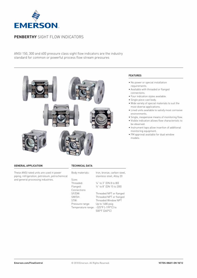
Penberthy Sight flow indicatorS
anSi 150, 300 and 600 pressure class sight flow indicators are the industry standard for common or powerful process flow stream pressures
Features
• No power or special installation requirements.
• Available with threaded or flanged connections.
• Four indication styles available.• Single piece cast body.• Wide variety of special materials to suit the
most diverse applications.• Lined units available to satisfy most corrosive
environments.• Single, inexpensive means of monitoring flow.• Visible indication allows flow characteristic to
be observed.• Instrument taps allow insertion of additional
monitoring equipment.• FM approval available for dual window
models.
emerson.com/FinalControl © 2018 Emerson. All Rights Reserved. VCtDs-08601-en 18/12
General aPPliCation
these anSi rated units are used in power piping, refrigeration, petroleum, petrochemical and general processing industries.
teChniCal Data
Body materials: Iron, bronze, carbon steel, stainless steel, alloy 20
Sizesthreaded: ¼” to 3” (dn 8 to 80)flanged: ½” to 8” (dn 15 to 200)connectionsSf/dw: threaded nPt or flangedSM/SH: Threaded NPT or flangedStw: threaded window nPtPressure range: Up to 1480 psigtemperature range: -325°f (-199°c) to
500°f (260°c)
2
Penberthy Sight flow indicatorSOverview
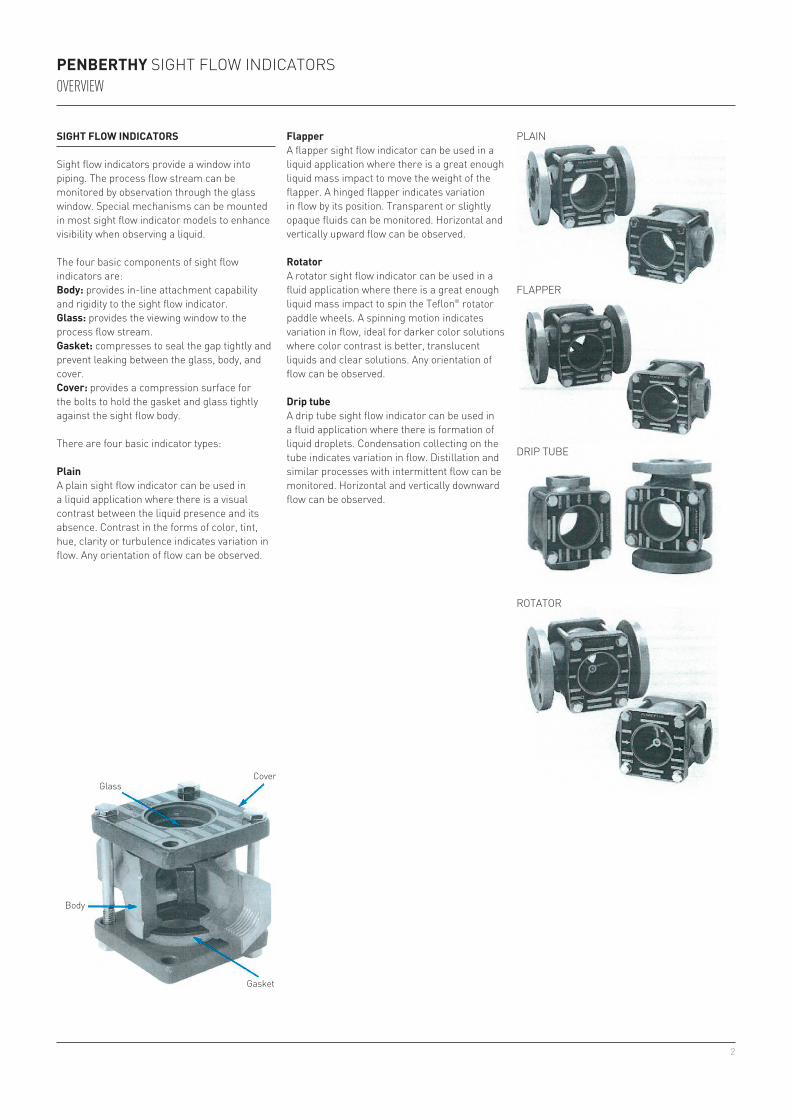
siGht Flow inDiCators
Sight flow indicators provide a window into piping. The process flow stream can be monitored by observation through the glass window. Special mechanisms can be mounted in most sight flow indicator models to enhance visibility when observing a liquid.
The four basic components of sight flow indicators are:body: provides in-line attachment capability and rigidity to the sight flow indicator.Glass: provides the viewing window to the process flow stream.Gasket: compresses to seal the gap tightly and prevent leaking between the glass, body, and cover.Cover: provides a compression surface for the bolts to hold the gasket and glass tightly against the sight flow body.
There are four basic indicator types:
PlainA plain sight flow indicator can be used in a liquid application where there is a visual contrast between the liquid presence and its absence. Contrast in the forms of color, tint, hue, clarity or turbulence indicates variation in flow. Any orientation of flow can be observed.
FlapperA flapper sight flow indicator can be used in a liquid application where there is a great enough liquid mass impact to move the weight of the flapper. A hinged flapper indicates variation in flow by its position. Transparent or slightly opaque fluids can be monitored. Horizontal and vertically upward flow can be observed.
rotatorA rotator sight flow indicator can be used in a fluid application where there is a great enough liquid mass impact to spin the teflon® rotator paddle wheels. a spinning motion indicates variation in flow, ideal for darker color solutions where color contrast is better, translucent liquids and clear solutions. any orientation of flow can be observed.
Drip tubeA drip tube sight flow indicator can be used in a fluid application where there is formation of liquid droplets. condensation collecting on the tube indicates variation in flow. Distillation and similar processes with intermittent flow can be monitored. Horizontal and vertically downward flow can be observed.
Plain
rotator
flaPPer
driP tUbe
glass
body
Gasket
Cover
3
300-150 -50 0 50 100 150 200 250-100
275
250
225
200
175
150
125
100-300 -200 -100 0 100 200 300 400 500
1000
1500
2000
BA
D
C - 150#E
300-150 -50 0 50 100 150 200 250-100
275
250
225
200
175
150
125
100-300 -200 -100 0 100 200 300 400 500
1000
1500
2000
BA
D
C - 150#E
teflon®
1 7 17.8 1½ 3.8 1 2.5 4⅝ 11.7 ½ - 13 1.31½ 8 20.3 2⅜ 6.0 1½ 3.8 5⅝ 14.3 ½ - 13 1.32 9 22.9 2⅞ 7.3 2 5.1 6⅝ 16.8 ¾ 1.93 11 27.9 3¾ 9.5 3 7.6 8¼ 21.0 ¾ 1.94 13 33.0 4¾ 12.1 4 10.2 9¼ 23.5 ¾ 1.96 16 40.6 7 17.8 6 15.2 12¾ 32.4 ⅞ 2.28 18 45.7 9 22.9 8 20.3 16⅛ 41.0 ⅞ 2.2
Penberthy Sight flow indicatorS
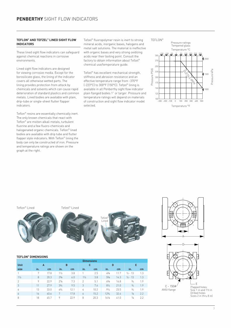
teFlon® anD teFzel® lineD siGht Flow inDiCators
these lined sight flow indicators can safeguard against chemical reactions in corrosive environments.
lined sight flow indicators are designed for viewing corrosive media. Except for the borosilicate glass, the lining of the indicator covers all otherwise wetted parts. The lining provides protection from attack by chemicals and solvents which can cause rapid deterioration of standard plastics and common metals. Lined bodies are available with plain, drip-tube or single-sheet flutter flapper indicators.
teflon® resins are essentially chemically inert. The only known chemicals that react with teflon® are molten alkali metals, turbulent fluorine and a few fluoro-chemicals and halogenated organic chemicals. teflon® lined bodies are available with drip tube and flutter flapper style indicators. with teflon® lining the body can only be constructed of iron. Pressure and temperature ratings are shown on the graph at the right.
Tefzel® fluoropolymer resin is inert to strong mineral acids, inorganic bases, halogens and metal salt solutions. The material is ineffective with organic bases and very strong oxidizing acids near their boiling point. Consult the factory to obtain information about Tefzel® chemical use/temperature guide.
Tefzel® has excellent mechanical strength, stiffness and abrasion resistance and an effective temperature range from -370°F (-223°C) to 300°F (150°C). Tefzel® lining is available in all Penberthy sight flow indicator plain flanged bodies 1” or larger. Pressure and temperature ratings will depend on materials of construction and sight flow indicator model selected.
teFlon® Dimensions
unit size
Dimensionsa b C D e
in. cm in. cm in. cm in. cm in. cm
(tapped holesSize 1 in and 1½ indrilled holesSizes 2 in thru 8 in)
temperature °c
temperature °f
Pres
sure
PSi
g
Pres
sure
kPa
Pressure ratingstempered glass
dUctile iron
anSi flange
teflon® lined Tefzel® lined
Tefzel® lined
4
B
A
A
CB
A
D
B
A
A
C
B
A
D
c - 150 P-cl
300-150 -50 0 50 100 150 200 250-100
275
250
225
200
175
150
125
100-300 -200 -100 0 100 200 300 400 500
1000
2000
1500
300-150 -50 0 50 100 150 200 250-100
275
250
225
200
175
150
125
100-300 -200 -100 0 100 200 300 400 500
1000
2000
1500
150 P-cl 150 P-cl
¼ 3 7.6 ⅞ 2.2 1 2.5 2 15/16 7.5 ¼ 0.6⅜ 3 7.6 ⅞ 2.2 1 2.5 2 15/16 7.5 ⅜ 1.0½ 3¾ 9.5 1¼ 3.2 1½ 3.8 3 15/16 10.0 ½ 1.3¾ 3¾ 9.5 1¼ 3.2 1½ 3.8 3 15/16 10.0 ¾ 1.91 4¼ 10.8 1½ 3.8 2 5.1 4 11/16 11.9 1 2.51¼ 5½ 14.0 2⅜ 6.0 2½ 6.4 5¾ 14.6 1¼ 3.21½ 5½ 14.0 2⅜ 6.0 2½ 6.4 5¾ 14.6 1½ 3.82 6¼ 15.9 2⅞ 7.3 3¼ 8.3 7⅜ 18.7 2 5.12½ 8½ 21.6 3¾ 9.5 4⅛ 10.5 9 3/16 23.3 2½ 6.43 8½ 21.6 3¾ 9.5 4⅛ 10.5 9 3/16 23.3 3 7.6
½ 4⅝ 11.7 1¼ 3.2 ½ 1.3 3 15/16 10.0¾ 4⅝ 11.7 1¼ 3.2 ¾ 1.9 3 15/16 10.01 5⅝ 14.3 1½ 3.8 1 2.5 4⅝ 11.71¼ 6½ 16.5 2⅜ 6.0 1¼ 3.2 5⅞ 14.91½ 6½ 16.5 2⅜ 6.0 1½ 3.8 5⅞ 14.92 7⅞ 20.0 2⅞ 7.3 2 5.1 7⅜ 18.72½ 9⅜ 23.8 3¾ 9.5 2½ 6.4 9 3/16 23.33 9⅜ 23.8 3¾ 9.5 3 7.6 9 3/16 23.34 11 27.9 4¾ 12.1 4 10.2 11⅜ 28.96 14¼ 36.2 7 17.8 6 15.2 15 15/16 40.58 16⅛ 41.0 9 22.9 8 20.3 18 5/16 46.5
Penberthy Sight flow indicatorS
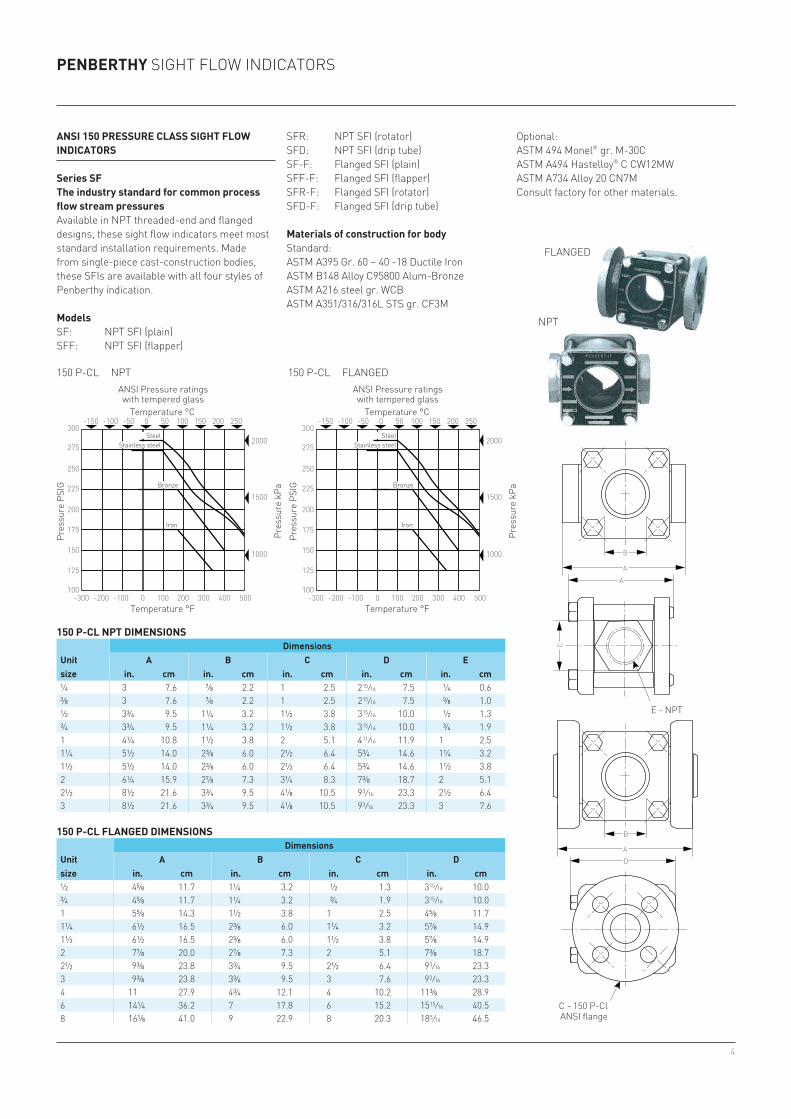
ansi 150 Pressure Class siGht Flow inDiCators
series sFthe industry standard for common process flow stream pressuresAvailable in NPT threaded-end and flanged designs, these sight flow indicators meet most standard installation requirements. Made from single-piece cast-construction bodies, these SFIs are available with all four styles of Penberthy indication.
modelsSf: nPt Sfi (plain)Sff: nPt Sfi (flapper)
Sfr: nPt Sfi (rotator)SFD: NPT SFI (drip tube)Sf-f: flanged Sfi (plain)Sff-f: flanged Sfi (flapper)Sfr-f: flanged Sfi (rotator)SFD-F: Flanged SFI (drip tube)
materials of construction for bodyStandard:ASTM A395 Gr. 60 – 40 -18 Ductile IronASTM B148 Alloy C95800 Alum-BronzeASTM A216 steel gr. WCBASTM A351/316/316L STS gr. CF3M
flanged
nPt
150 P-Cl nPt Dimensions
unit size
Dimensionsa b C D e
in. cm in. cm in. cm in. cm in. cm
150 P-Cl FlanGeD Dimensions
unit size
Dimensionsa b C D
in. cm in. cm in. cm in. cm
e - nPt
anSi flange
anSi Pressure ratings with tempered glass
anSi Pressure ratings with tempered glass
temperature °c
Steel SteelStainless steel Stainless steel
Bronze Bronze
iron iron
temperature °c
temperature °f temperature °f
Pres
sure
PSi
g
Pres
sure
PSi
gPr
essu
re k
Pa
Pres
sure
kPa
nPt flanged
optional:ASTM 494 Monel® gr. M-30CASTM A494 Hastelloy® C CW12MWASTM A734 Alloy 20 CN7Mconsult factory for other materials.

5
300 P-cl
600 P-cl
Penberthy Sight flow indicatorS
industrial areas where high pressure pipelines are used include:∙ Power piping - Steam electric generation
stations; industrial and institutional plants; central and district heating plants.
∙ refrigeration piping.∙ Petroleum - Petroleum refinery piping;
loading terminal; gas metering; main and service lines; bulk plant and compressor stations compounding plant; storage facilities; gas pipelines.
∙ agricultural piping.∙ Pharmaceutical/chemical- Alkylation/
carboxylation; dehydration/halogenation; condensation/cyclization; other complex chemical conversions.
materials of construction for bodyStandard:ASTM A216 steel gr. WCBASTM A351/316/316L316 STS gr. CF3M
optional:ASTM 494 Monel® gr. M-30CASTM A494 Hastelloy® C CW12MWASTM A734 Alloy 20 CN7Mconsult factory for other materials.
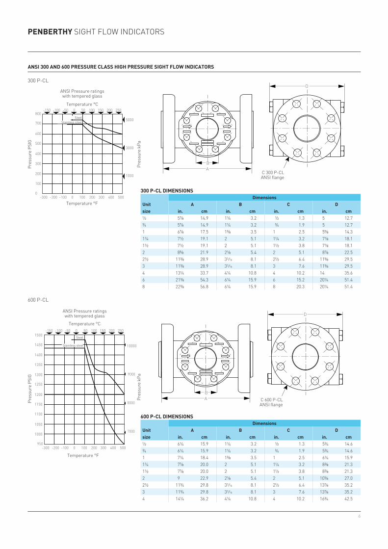
ansi 300 anD 600 Pressure Class hiGh Pressure siGht Flow inDiCators
series sm and shPowerful flow streams are mastered by heavy duty constructionAvailable in flanged models only, these sight flow indicators meet tough anSi standards for 300 and 600 pressure class requirements. Made from single-piece, cast-construction bodies, these SFIs are available with all four styles of Penberthy indication.
models300 pressure class seriesSM: NPT SFI (plain)SMF: NPT SFI (flapper)SMR: NPT SFI (rotator)SMD: NPT SFI (drip tube)SM-F: Flanged SFI (plain)SMF-F: Flanged SFI (flapper)SMR-F: Flanged SFI (rotator)SMD-F: Flanged SFI (drip tube)
600 pressure class seriesSh: nPt Sfi (plain)Shf: nPt Sfi (flapper)Shr: nPt Sfi (rotatorSHD: NPT SFI (drip tube)Sh-f: flanged Sfi (plain)Shf-f: flanged Sfi (flapper)Shr-f: flanged Sfi (rotator)SHD-F: Flanged SFI (drip tube)
high pressure sight flow indicator applicationsnaturally occurring high pressure wells (natural gas, petroleum, geothermal steam) and long-distance pumping (transportation) of liquids and gases require high pressure sight flow indicators to observe fluid dynamics.
chemical processes often require that fluids be in their liquid state. To achieve this, the chemical must remain under pressure at all times so that it can be transported using high pressure pumps. Observing the flow of chemicals such as argon, hydrogen, nitrogen, Oxygen, Carbon Monoxide, Propane, Ethyl Methyl Ether, Butane, Isobutane, Pentane in their liquid state requires high pressure sight flow indicators.
6
BA
800
300 P-CL-150 -50 0 50 100 150 200 250-100
700
600
500
400
300
200
100
0-300 -200 -100 0 100 200 300 400 500
1000
3000
5000
600 P-CL-150 -50 0 50 100 150 200 250-100
1000
1050
1100
1150
1200
1250
1300
1350
1400
1450
1500
950-300 -200 -100 0 100 200 300 400 500
9000
8000
7000
10000
D
D
ANSI FLANGE
BA
BA
800
300 P-CL-150 -50 0 50 100 150 200 250-100
700
600
500
400
300
200
100
0-300 -200 -100 0 100 200 300 400 500
1000
3000
5000
600 P-CL-150 -50 0 50 100 150 200 250-100
1000
1050
1100
1150
1200
1250
1300
1350
1400
1450
1500
950-300 -200 -100 0 100 200 300 400 500
9000
8000
7000
10000
D
D
ANSI FLANGE
BA
300 P-cl
600 P-cl
½ 5⅞ 14.9 1¼ 3.2 ½ 1.3 5 12.7¾ 5⅞ 14.9 1¼ 3.2 ¾ 1.9 5 12.71 6⅞ 17.5 1⅜ 3.5 1 2.5 5⅝ 14.31¼ 7½ 19.1 2 5.1 1¼ 3.2 7⅛ 18.11½ 7½ 19.1 2 5.1 1½ 3.8 7⅛ 18.12 8⅝ 21.9 2⅛ 5.4 2 5.1 8⅞ 22.52½ 11⅜ 28.9 3 3/16 8.1 2½ 6.4 11⅝ 29.53 11⅜ 28.9 3 3/16 8.1 3 7.6 11⅝ 29.54 13¼ 33.7 4¼ 10.8 4 10.2 14 35.66 21⅜ 54.3 6¼ 15.9 6 15.2 20¼ 51.48 22⅜ 56.8 6¼ 15.9 8 20.3 20¼ 51.4
½ 6¼ 15.9 1¼ 3.2 ½ 1.3 5¾ 14.6¾ 6¼ 15.9 1¼ 3.2 ¾ 1.9 5¾ 14.61 7¼ 18.4 1⅜ 3.5 1 2.5 6¼ 15.91¼ 7⅞ 20.0 2 5.1 1¼ 3.2 8⅜ 21.31½ 7⅞ 20.0 2 5.1 1½ 3.8 8⅜ 21.32 9 22.9 2⅛ 5.4 2 5.1 10⅝ 27.02½ 11¾ 29.8 3 3/16 8.1 2½ 6.4 13⅞ 35.23 11¾ 29.8 3 3/16 8.1 3 7.6 13⅞ 35.24 14¼ 36.2 4¼ 10.8 4 10.2 16¾ 42.5
Penberthy Sight flow indicatorS
ansi 300 anD 600 Pressure Class hiGh Pressure siGht Flow inDiCators
300 P-Cl Dimensions
unit size
Dimensionsa b C D
in. cm in. cm in. cm in. cm
600 P-Cl Dimensions
unit size
Dimensionsa b C D
in. cm in. cm in. cm in. cm
c 300 P-clanSi flange
c 600 P-clanSi flange
anSi Pressure ratings with tempered glass
anSi Pressure ratings with tempered glass
temperature °c
temperature °c
temperature °f
temperature °f
Pres
sure
PSi
gPr
essu
re P
Sig
Pres
sure
kPa
Pres
sure
kPa
Steel
Steel
Stainless steel
Stainless steel
7
Penberthy Sight flow indicatorS
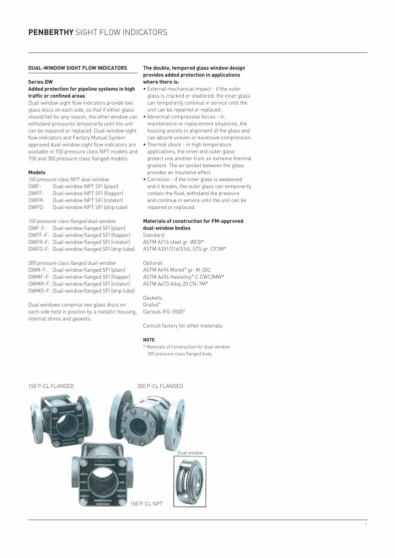
Dual-winDow siGht Flow inDiCators
series Dwadded protection for pipeline systems in high traffic or confined areasDual-window sight flow indicators provide two glass discs on each side, so that if either glass should fail for any reason, the other window can withstand pressures temporarily until the unit can be repaired or replaced. Dual-window sight flow indicators and Factory Mutual System approved dual-window sight flow indicators are available in 150 pressure class NPT models and 150 and 300 pressure class flanged models.
models150 pressure class NPT dual-windowdwf: dual-window nPt Sfi (plain)dwff: dual-window nPt Sfi (flapper)dwfr: dual-window nPt Sfi (rotator)DWFD: Dual-window NPT SFI (drip tube)
150 pressure class flanged dual-windowdwf-f: dual-window flanged Sfi (plain)dwff-f: dual-window flanged Sfi (flapper)dwfr-f: dual-window flanged Sfi (rotator)DWFD-F: Dual-window flanged SFI (drip tube)
300 pressure class flanged dual-windowDWM-F: Dual-window flanged SFI (plain)DWMF-F: Dual-window flanged SFI (flapper)DWMR-F: Dual-window flanged SFI (rotator)DWMD-F: Dual-window flanged SFI (drip tube)
dual windows comprise two glass discs on each side held in position by a metallic housing, internal shims and gaskets.
the double, tempered glass window design provides added protection in applications where there is:∙ External mechanical impact - if the outer
glass is cracked or shattered, the inner glass can temporarily continue in service until the unit can be repaired or replaced.
∙ Abnormal compressive forces - in maintenance or replacement situations, the housing assists in alignment of the glass and can absorb uneven or excessive compression.
∙ Thermal shock - in high temperature applications, the inner and outer glass protect one another from an extreme thermal gradient. The air pocket between the glass provides an insulative effect.
∙ Corrosion - if the inner glass is weakened and it breaks, the outer glass can temporarily contain the fluid, withstand the pressure and continue in service until the unit can be repaired or replaced.
materials of construction for Fm-approved dual-window bodiesStandard:ASTM A216 steel gr. WCB*ASTM A351/316/316L STS gr. CF3M*
optional:ASTM A494 Monel® gr. M-30CASTM A494 Hastelloy® C CW12MW*ASTM A473 Alloy 20 CN-7M*
Gaskets:grafoil®
Garlock IFG-5500®
consult factory for other materials.
note* Materials of construction for dual-window
300 pressure class flanged body.
150 P-cl flanged
150 P-cl nPt
dual window
300 P-cl flanged
8
B
A
300-150 -50 0 50 100 150 200 250-100
275
250
225
200
175
150
125
100-300 -200 -100 0 100 200 300 400 500
1000
1500
2000
B
B
A
A
D
D
D
C
STS STL, STS
300-150 -50 0 50 100 150 200 250-100
275
250
225
200
175
150
125
100-300 -200 -100 0 100 200 300 400 500
1000
1500
2000
STS STL, STS
800-150 -50 0 50 100 150 200 250-100
700
600
500
400
300
200
100
0-300 -200 -100 0 100 200 300 400 500
1000
1500
5000
STS STL, STS
B
A
300-150 -50 0 50 100 150 200 250-100
275
250
225
200
175
150
125
100-300 -200 -100 0 100 200 300 400 500
1000
1500
2000
B
B
A
A
D
D
D
C
STS STL, STS
300-150 -50 0 50 100 150 200 250-100
275
250
225
200
175
150
125
100-300 -200 -100 0 100 200 300 400 500
1000
1500
2000
STS STL, STS
800-150 -50 0 50 100 150 200 250-100
700
600
500
400
300
200
100
0-300 -200 -100 0 100 200 300 400 500
1000
1500
5000
STS STL, STS
300-150 -50 0 50 100 150 200 250-100
275
250
225
200
175
150
125
100-300 -200 -100 0 100 200 300 400 500
1000
2000
1500
300-150 -50 0 50 100 150 200 250-100
275
250
225
200
175
150
125
100-300 -200 -100 0 100 200 300 400 500
1000
2000
1500
BA
800
300 P-CL-150 -50 0 50 100 150 200 250-100
700
600
500
400
300
200
100
0-300 -200 -100 0 100 200 300 400 500
1000
3000
5000
600 P-CL-150 -50 0 50 100 150 200 250-100
1000
1050
1100
1150
1200
1250
1300
1350
1400
1450
1500
950-300 -200 -100 0 100 200 300 400 500
9000
8000
7000
10000
D
D
ANSI FLANGE
BA
½ 4⅝ 11.7 1¼ 3.2 ½ 1.3 5 3/16 13.2¾ 4⅝ 11.7 1¼ 3.2 ¾ 1.9 5 3/16 13.21 5⅝ 14.3 1½ 3.8 1 2.5 5⅞ 14.91¼ 6½ 16.5 2⅜ 6.0 1¼ 3.2 7¾ 19.71½ 6½ 16.5 2⅜ 6.0 1½ 3.8 7¾ 19.72 7⅞ 20.0 2⅞ 7.3 2 5.1 9⅝ 24.42½ 9⅜ 23.8 3¾ 9.5 2½ 6.4 12 5/16 31.33 9⅜ 23.8 3¾ 9.5 3 7.6 12 5/16 31.34 11 27.9 4¾ 12.1 4 10.2 14⅞ 37.86 14¼ 36.2 7 17.8 6 15.2 21 13/16 55.48 16⅛ 41.0 9 22.9 8 20.3 25 63.5
½ 5⅞ 14.9 1¼ 3.2 ½ 1.3 6⅝ 16.8¾ 5⅞ 14.9 1¼ 3.2 ¾ 1.9 6⅝ 16.81 6⅞ 17.5 1⅜ 3.5 1 2.5 7¾ 19.71¼ 7½ 19.1 2 5.1 1¼ 3.2 8⅛ 20.61½ 7½ 19.1 2 5.1 1½ 3.8 8⅛ 20.62 8⅝ 21.9 2⅛ 5.4 2 5.1 12⅛ 30.82½ 11⅜ 28.9 3 3/16 8.1 2½ 6.4 16⅜ 41.63 11⅜ 28.9 3 3/16 8.1 3 7.6 16⅜ 41.64 13¼ 33.7 4¼ 10.8 4 10.2 20 50.86 21⅜ 54.3 6¼ 15.9 6 15.2 27¾ 70.58 22⅜ 56.8 6¼ 15.9 8 20.3 27¾ 70.5
¼ 3 7.6 ⅞ 2.2 1 2.5 3 11/16 9.4 ¼ 0.6⅜ 3 7.6 ⅞ 2.2 1 2.5 3 11/16 9.4 ⅜ 1.0½ 3¾ 9.5 1¼ 3.2 1½ 3.8 5 3/16 13.2 ½ 1.3¾ 3¾ 9.5 1¼ 3.2 1½ 3.8 5 3/16 13.2 ¾ 1.91 4¼ 10.8 1½ 3.8 2 5.1 5⅞ 14.9 1 2.51¼ 5½ 14.0 2⅜ 6.0 2½ 6.4 7⅝ 19.4 1¼ 3.21½ 5½ 14.0 2⅜ 6.0 2½ 6.4 7⅝ 19.4 1½ 3.82 6¼ 15.9 2⅞ 7.3 3¼ 8.3 9⅝ 24.4 2 5.12½ 8½ 21.6 3¾ 9.5 4⅛ 10.5 12 5/16 31.3 2½ 6.43 8½ 21.6 3¾ 9.5 4⅛ 10.5 12 5/16 31.3 3 7.6
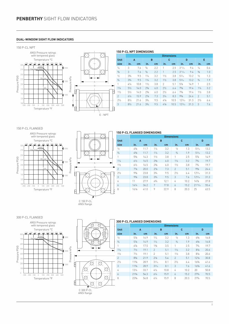
Penberthy Sight flow indicatorS
Dual-winDow siGht Flow inDiCators
150 P-Cl nPt Dimensions
unit size
Dimensionsa b C D e
in. cm in. cm in. cm in. cm in. cm
150 P-Cl FlanGeD Dimensions
unit size
Dimensionsa b C D
in. cm in. cm in. cm in. cm
300 P-Cl FlanGeD Dimensions
unit size
Dimensionsa b C D
in. cm in. cm in. cm in. cm
c 150 P-clanSi flange
c 300 P-clanSi flange
anSi Pressure ratings with tempered glass
temperature °c
temperature °f
Pres
sure
PSi
g
Pres
sure
kPa
e - nPt
anSi Pressure ratings with tempered glass
anSi Pressure ratings with tempered glass
temperature °c
temperature °c
temperature °f
temperature °f
Pres
sure
PSi
gPr
essu
re P
Sig
Pres
sure
kPa
Pres
sure
kPa
150 P-cl nPt
150 P-cl flanged
300 P-cl flanged
Steel
Steel
Stainless steel
Stainless steel
Bronze
Bronze
iron
iron
SteelStainless steel

9
BC
D
A
Stwr
Stwd
Stwf
Stw
¼ 3 7.6 13/16 2.1 1 2.5 2 7/16 6.2 ¼ 0.6⅜ 3 7.6 13/16 2.1 1 2.5 2 7/16 6.2 ⅜ 1.0½ 3¾ 9.5 1 3/16 3.0 1½ 3.8 3 5/16 8.4 ½ 1.3¾ 3¾ 9.5 1 3/16 3.0 1½ 3.8 3 5/16 8.4 ¾ 1.91 4¼ 10.8 1 7/16 3.7 2 5.1 3¾ 9.5 1 2.51¼ 5½ 14.0 2¼ 5.7 2½ 6.4 4½ 11.4 1¼ 3.21½ 5½ 14.0 2¼ 5.7 2½ 6.4 4½ 11.4 1½ 3.82 6¼ 15.9 2⅞ 7.3 3¼ 8.3 6 15.2 2 5.1
Penberthy Sight flow indicatorS
threaDeD winDow siGht Flow inDiCators
series stwa slender body with easy access windows is a popular alternative to traditional sight flow indicatorsthreaded window sight flow indicators are labelled with the company logo as well as pressure and temperature ratings. Available in nPt threaded-end designs, all threaded window sight flow indicator sizes meet ANSI 150 pressure class standards. they are available with all four styles of Penberthy indication.
modelsStw: nPt threaded window Sfi (plain)Stwf: nPt threaded window Sfi (flapper)Stwr: nPt threaded window Sfi (rotator)STWD: NPT threaded window SFI (drip tube)
the windows are screwed into the single-piece cast sight flow body.
materials of construction for all threaded window bodiesStandard:ASTM A395 Gr. 60-40-18 Ductile ironASTM B148 Alloy C95800 BronzeASTM A216 steel gr. WCBASTM A351/316/316L STS gr. CF3M
Spanner wreches
threaDeD winDow siGht Flow inDiCators
unit size
Dimensionsa b C D e
in. cm in. cm in. cm in. cm in. cm
e - nPt
The threaded window design is an alternative style that is interchangeable with most applications using anSi 150 pressure class sight flow indicators with bolt-on covers. Instead of unbolting the outer glass covers, these threaded windows are removed for cleaning or replacement with a spanner wrench.
Spanner wrenches for removing windows are available. The spanner wrenches have a ½” drive socket to be used with a torque wrench.
optional:ASTM 494 Monel® gr. M-30CASTM A494 Hastelloy® C CW12MWASTM A734 Alloy 20 CN7Mconsult factory for other materials.
material of construction for coversBrass and 316 stainless barstockAll bodies are ANSI 150 pressure class regardless of size.
10
0 100-100-200-300 200 300 400 500
Penberthy Sight flow indicatorS
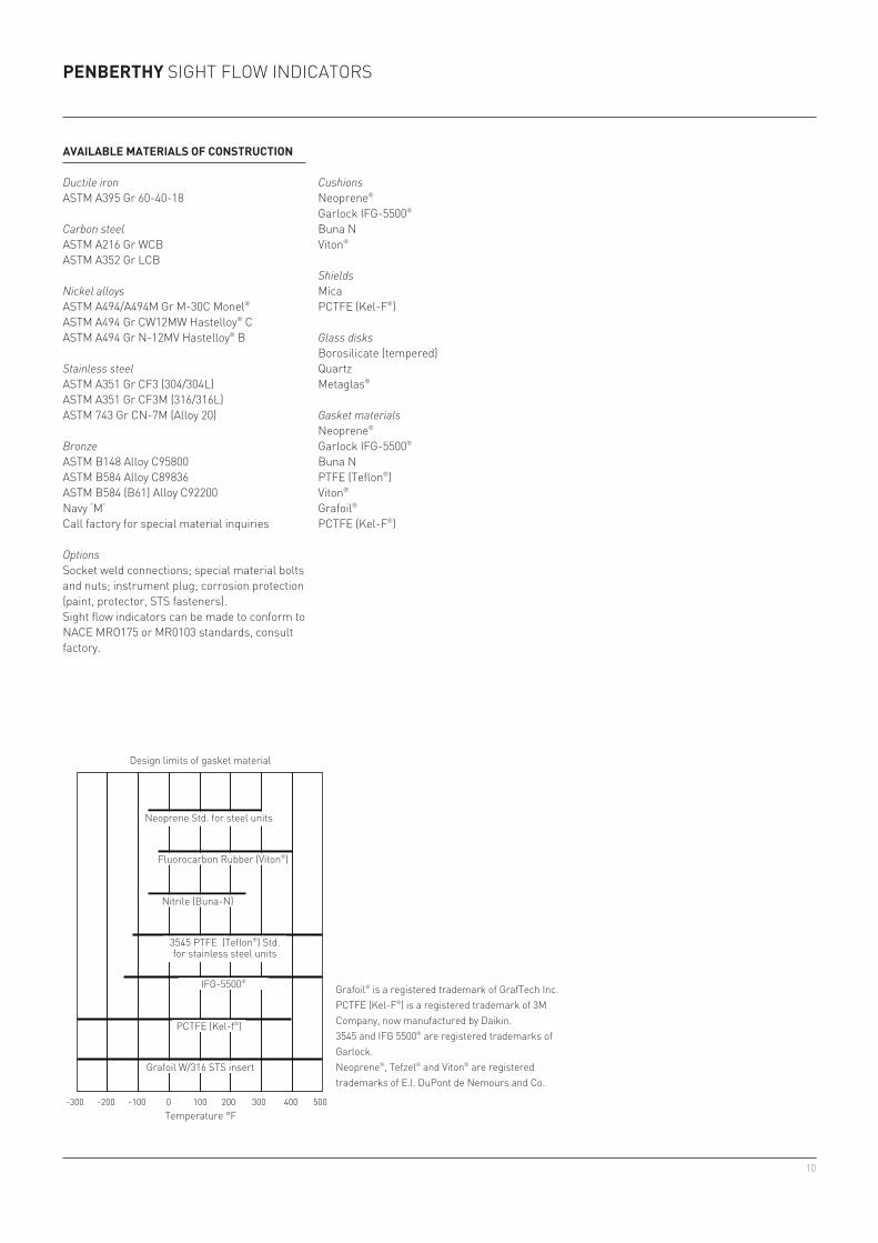
aVailable materials oF ConstruCtion
Ductile ironASTM A395 Gr 60-40-18
Carbon steelASTM A216 Gr WCBASTM A352 Gr LCB
Nickel alloysASTM A494/A494M Gr M-30C Monel®
ASTM A494 Gr CW12MW Hastelloy® cASTM A494 Gr N-12MV Hastelloy® b
Stainless steelASTM A351 Gr CF3 (304/304L)ASTM A351 Gr CF3M (316/316L)ASTM 743 Gr CN-7M (Alloy 20)
BronzeASTM B148 Alloy C95800ASTM B584 Alloy C89836ASTM B584 (B61) Alloy C92200Navy ‘M’call factory for special material inquiries
OptionsSocket weld connections; special material bolts and nuts; instrument plug; corrosion protection (paint, protector, StS fasteners).Sight flow indicators can be made to conform to NACE MRO175 or MR0103 standards, consult factory.
Cushionsneoprene®
Garlock IFG-5500®
buna nViton®
ShieldsMicaPctfe (Kel-f®)
Glass disksborosilicate (tempered)QuartzMetaglas®
Gasket materialsneoprene®
Garlock IFG-5500®
buna nPtfe (teflon®)Viton®
grafoil®
Pctfe (Kel-f®)
neoprene Std. for steel units
Fluorocarbon Rubber (Viton®)
nitrile (buna-n)
3545 Ptfe (teflon®) Std. for stainless steel units
ifg-5500®
Pctfe (Kel-f®)
grafoil w/316 StS insert
temperature °f
Design limits of gasket material
grafoil® is a registered trademark of GrafTech Inc.Pctfe (Kel-f®) is a registered trademark of 3M Company, now manufactured by Daikin.3545 and ifg 5500® are registered trademarks of Garlock.neoprene®, Tefzel® and Viton® are registered trademarks of E.I. DuPont de Nemours and Co.

11
c
a
b
¼ 29/32 2.3 11/32 0.9 ⅞ 2.2 ¼ 0.6⅜ 1 2.5 15/32 1.2 1 2.5 ⅜ 1.0½ 1⅛ 2.9 19/32 1.5 1⅛ 2.9 ½ 1.3¾ 1⅜ 3.5 ¾ 1.9 1⅜ 3.5 ¾ 1.91 19/16 4.0 15/16 2.4 1⅝ 4.1 1 2.51¼ 1 13/16 4.6 1 9/32 3.3 2 5.1 1¼ 3.21½ 1 15/16 4.9 1 9/16 4.0 2¼ 5.7 1½ 3.82 2 9/32 5.8 1 15/16 4.9 2¾ 7.0 2 5.12½ 2 11/16 6.8 2 5/16 5.9 3½ 8.9 2½ 6.43 3⅛ 7.9 2 15/16 7.5 4½ 11.4 3 7.6
Penberthy Sight flow indicatorS
threaDeD siGht winDows
a quick solution for pipe or tank observationAvailable with brass or stainless steel retaining rings, these sight windows can be used anywhere that a ¼" to 3" piping 't' or a female NPT exists.
the threaded Sight windows are rated at anSi 150 P-CL using tempered borosilicate glass.
models wtSl .............................threaded Sight windows
threaDeD siGht winDows
unit size
Dimensionsa b C D
in. cm in. cm in. cm in. cm
'd' nPt
Specifications subject to change without notice
Spanner wrenches
the threaded Sight window is similar in design to the threaded window Sight flow indicator. the outer retaining ring compresses the glass between the gasket and cushion.
Spanner wrenches for window removal are available from Penberthy. The spanner wrenches have a ¼" or ½" drive socket for torque wrench. all threaded Sight windows are machined from hex barstock.
materials of construction for threaded glass housing Hex Brass, Carbon Steel and Stainless Steel barstock. Consult factory for other material.

12
Penberthy Sight flow indicatorS
Cross reFerenCe GuiDe
Use Emerson’s Penberthy sight flow indicators or settle for second best. When designing a new process flow system or replacing an existing model, incorporate Penberthy models by using this cross reference chart and install with confidence.
sPeCial siGht Flow inDiCators
In addition to the broad standard range of Penberthy sight flow indicators, Emerson has the ability to create innumerable variants and unique solutions. Our metallurgy staff is capable of creating unique casting designs, with SFIs up to 16” having been produced. Some industries require special connections with high precision machining needed to achieve the mandatory tight tolerances. We can use our skilled machinists to create a large variety of connection ends including butt-weld or socket weld end connections. Flat surfaces are cast into bodies to provide for gaging and sampling ports.
Description Penberthy Jacoby-tarbox Papailias Co.anSi 150 P-cl Sfi - flapper Sff 100-S fiS-fanSi 150 P-cl Sfi - nPt rotator Sfr 200-S fiS-rANSI 150 P-CL NPT - Drip tube Sfd 300-S fiS-danSi 300 P-cl high pressure Sfi SM-F f-910-hP 300 P-cl fif-f/hP3anSi 600 P-cl high pressure Sfi Sh-f f-910-hP 600 P-cl fif-f/hP6FM Approved 300 P-CL Dual window SFI-Flanged DWM-F F-910-HP (FM) -FM Approved 150 P-CL Dual window SFI-Flanged dwf-f 910F (NF)(FM) -FM Approved 150 P-CL Dual window SFI-Flanged dwf S-100-HP (FM) -threaded window Sfi - flapper Stwf 100-S -threaded window Sfi - rotator Stwr 300-S -Threaded window SFI - Drip tube Stwd 200-S -threaded sight window 150 P-cl wtSl S-5400 -
13
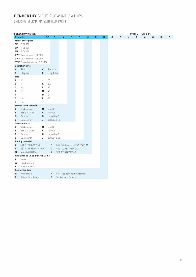
Penberthy Sight flow indicatorSOrdering infOrmatiOn sight flOw part 1
seleCtion GuiDe Part 2 - PaGe 14example: sF P a C s m X n G b X e a C D emodel descriptionsF P cl 150sm P cl 300sh P cl 600DwF dual window P cl 150Dwm dual window P cl 300stw threaded window P cl 150operation styleP Plain r rotatorF flapper D Drip tubesizea ¼" J 2"b ⅜" K 2½"C ½" l 3"e ¾" m 4"F 1" n 6"G 1¼" P 8"h 1½"wetted parts materialC Carbon steel m Monels 316-316L SST a alloy 20b Bronze h hastelloy cG Dugtile iron J 304/304 l SStCover materialC Carbon steel m Monels 316-316L SST a alloy 20b Bronze h hastelloy cG Dugtile iron J 304/304 l SStbolting material C Stl a193 b7/a194 2h n STL NACE A193 B7M/A194 2HMs SST A193 B8M/A194 8M G Stl a320 l7/a194 gr.4m Monel 400 B164 J SSt a193 b8/a194 8naCe mr-01-75 and/or mr-01-03X nonew nace wettede EnvironmentalConnection typen nPt female F Flat face flanged (bronze/iron)r raised face flanged s Socket weld female

14
Penberthy Sight flow indicatorSOrdering infOrmatiOn sight flOw part 2
seleCtion GuiDeexample: G b X e a C D eGasket materialG Grafoil w/Mylar insert n neoprenea Garlock IFG-5500 P Pctfes grafoil w/SSt insert t Ptfe 3545J gylon 3500 u buna-nK Garlock 3300 V Vitonl gylon 3510 y gylon 3504Cushion materialG Grafoil w/Mylar insert n neoprenea Garlock IFG-5500 t Ptfe 3545s grafoil w/SSt insert u buna-nJ gylon 3500 V VitonK Garlock 3300 y gylon 3504l gylon 3510Paint specificationX none F inter. 228, 228s Standard G ameron d9, 2, 450ho offshore Spec 2600 paint h amercoat 872a offshore Spec 2600 paint only J ameron d9D ameron d9, 450h K inter. 269, 990e ameron d9, PSX892hSoption 1 descriptionX None C Pctfe shields e Quartz t TFE lined bodym Metaglas r Metaglas/PCFTE shieldsa Mica shields V-4option 2 descriptionX None b 125-250 aarh finisha Nameplate on back side option 3 descriptionX None D 316 SSt flappera bolt-on flange protectors e Special teflon flapperb Screw heads on back side F Tefzel lined bodyC hastelloy c rotator pinoption 4 descriptionX none e Cover Offshore painteda Belleville washers F origin not china/india/eeUrC Screw heads on back side G dye penetrant test castingD Place of origin not chinaoption 5 descriptionX none e USa origin onlya for John c. ernst co. F Special thicknessb For cleveland gear G Ultrasonic test castingC Special screw length h radiographic test castingD for archon

15
Penberthy Sight flow indicatorSOrdering infOrmatiOn sight windOw
seleCtion GuiDeexample: wtsl a C s Xmodel descriptionwtsl nPt male sight window 150 P clsizea ¼" G 1¼"b ⅜" h 1½"C ½" J 2"e ¾" K 2½"F 1" l 3"body materialC Carbon steel a alloy 20s 316-316L SST h hastelloy cm Monel b BronzeCover materials 316-316L SST b Bronze naCe mr-01-75 and/or mr-01-03X nonew nace wettede Environmental
seleCtion GuiDe (ContinueD)example: G s X aGasket materialG Grafoil w/Mylar insert u buna-ns grafoil w/SSt insert V Vitona Garlock IFG-5500 n neoprenet Ptfe 3545Cushion materialG Grafoil w/Mylar insert a Garlock IFG-5500s grafoil w/SSt insert t Ptfe 3545Paint specificationX none s Standardoption 1 descriptionX None a USa only

16
Neither Emerson, Emerson Automation Solutions, nor any of their affiliated entities assumes responsibility for the selection, use or maintenance of any product. Responsibility for proper selection, use, and maintenance of any product remains solely with the purchaser and end user.
Penberthy is a mark owned by one of the companies in the Emerson Automation Solutions business unit of Emerson Electric Co. Emerson Automation Solutions, Emerson and the Emerson logo are trademarks and service marks of Emerson Electric Co. All other marks are the property of their respective owners.
The contents of this publication are presented for informational purposes only, and while every effort has been made to ensure their accuracy, they are not to be construed as warranties or guarantees, express or implied, regarding the products or services described herein or their use or applicability. All sales are governed by our terms and conditions, which are available upon request. We reserve the right to modify or improve the designs or specifications of such products at any time without notice.
emerson.com/finalcontrol