Embed Size (px)
Citation preview

Pellegrino, Gianmario and Cupertino, Francesco and Gerada, C. (2014) Automatic design of Synchronous Reluctance motors focusing on barrier shape optimization. IEEE Transactions on Industry Applications, 51 (2). pp. 1465-1474. ISSN 1939-9367
Access from the University of Nottingham repository: http://eprints.nottingham.ac.uk/37665/1/Automatic%20Design%20of%20Synchronous%20Reluctance%20Motors%20Focusing%20on%20Barrier%20Shape%20Optimization.pdf
Copyright and reuse:
The Nottingham ePrints service makes this work by researchers of the University of Nottingham available open access under the following conditions.
This article is made available under the University of Nottingham End User licence and may be reused according to the conditions of the licence. For more details see: http://eprints.nottingham.ac.uk/end_user_agreement.pdf
A note on versions:
The version presented here may differ from the published version or from the version of record. If you wish to cite this item you are advised to consult the publisher’s version. Please see the repository url above for details on accessing the published version and note that access may require a subscription.
For more information, please contact [email protected]
Abstract— The automated design of Synchronous Reluctance
motors based on Multi-Objective, Genetic Optimization and Finite
Element Analysis is considered in this paper. Three types of
barrier shapes are considered, all described by an effective, limited
set of input variables. The three solutions are investigated to
establish which of the geometries can give the best torque output
and also which one represents the best compromise between
output performance and computational time. The analysis
presented in this paper shows that Synchronous Reluctance
motors designed automatically can give a good performance, can
be designed in a reasonable time and it is also shown that not all
design degrees of freedom are useful in terms of motor
performance. Two prototypes of automatically designed machines
have been fabricated and experimentally compared to a third
prototype designed according to state-of-the-art design principles.
Index Terms — AC Machines, AC Motors, AC Drives,
Synchronous Motor Drives, Synchronous Reluctance Machines,
Rotor Design, Design optimization, Pareto Optimization, Finite
Element Analysis.
I. INTRODUCTION
ynchronous Reluctance (SyR) motors are a viable
alternative to inverter-driven Induction Motors (IM) due to
their higher efficiency, lower rotor temperature and their higher
transient overload capability. SyR motors have been studied
comprehensively in the 1990s [1-5] and recently reconsidered
by major manufacturers [6]. In addition, they are the basis for
permanent magnet- (PM-) assisted SyR motors, which are a
class of Interior PM (IPM) machines of particular interest for
their reduced PM quantity [7-8].
The design of transverse laminated SyR rotors with multiple
flux barriers has been formalized through the years by many
authors. Yet, a standard design approach is an open challenge,
in particular for industrial applications. Finite element analysis
(FEA) is adopted by all authors, including the ones that base the
design on analytical models [9-11]. This is mainly due to the
impact of magnetic saturation which is significant and
consequently linear magnetic models are inaccurate.
Finite element based design of SyR motors through artificial
intelligence techniques is discouraged due to the long
simulation times as a result of the numerous FEA evaluations
demanded by the search algorithms. This is the case for any
kind of optimization algorithim (OA) applied to this motor type
as a result of the combination of the high number of candidate
solutions and the non-negligible time for FEA evaluation for
each candidate. On one hand, the OA will require a number of
tentative motor design evaluations depending on the algorithm
and on the proper conditioning of the problem (choice of the
input variables and selection of the optimization goals). On the
other hand, SyR machines tend to require many FEA runs for
their performance to be evaluated. For example, Surface
mounted PM machines can be evaluated quite comprehensively
via a single static FEA simulation [12, 13], which is not the case
here.
Returning to the number of evaluations required by the OA
to converge, the set of geometric parameters describing the
multi-barrier rotor plays a key role. In the literature, this varies
and it is generally high and proportional to the number of layers
[14].
In previous work, the choice and compromise between the
variables for a good description of the rotor geometry and for a
fast FEA evaluation of the candidate motors were addressed
[15]. A two-step procedure for a time efficient multi-objective
genetic algorithm (MOGA) was proposed in [16], having as
output a front of SyR motor designs which are Pareto-optimized
in terms of torque and torque ripple. In [17] other types of
barriers were considered, as an alternative to the circular
barriers of [15,16].
This paper further investigates the compromises to be had in
choosing a barrier geometry which is more suitable for
automatic design. Three-layer rotors will be considered in this
paper and three topological geometries will be defined and used
for the automatic design. The first having flux barriers of
circular shape and the other two with angled barriers made of
straight consecutive segments as illustrated in Fig. 1 and 2. The
torque-vs-torque ripple performance obtained with the three
geometries is compared along with the respective
computational times. The number of geometric variables and
their effect on computational time are also investigated. The
two-step use of the MOGA introduced in [16] is reconsidered
and a new procedure for the final Local-Search refinement is
proposed. Finally, the motors designed automatically by the
MOGA are compared experimentally with a state-of-the-art
motor.
II. ROTOR GEOMETRIES CONSIDERED
The 3-layer rotor represented in Fig. 1a has circular or C-
Automatic Design of
Synchronous Reluctance Motors focusing on Barrier
Shape Optimization.
G. Pellegrino, Senior Member, IEEE, F. Cupertino, Senior Member, IEEE, and C. Gerada, Member, IEEE
S
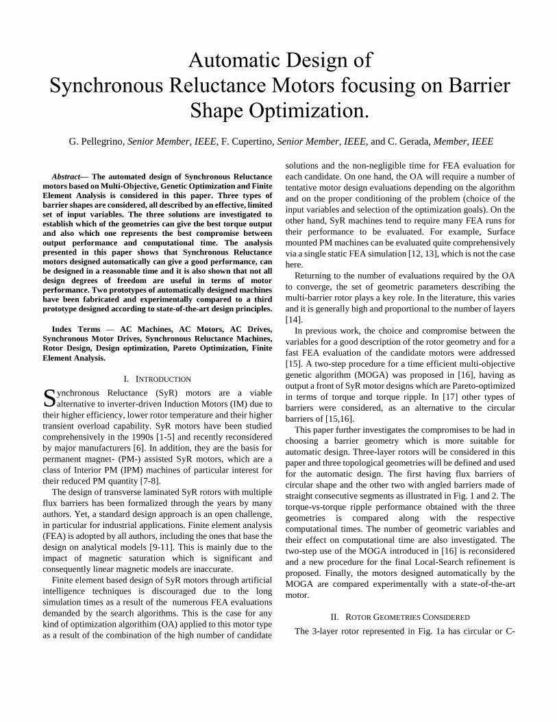
shaped barriers and it is hence referred to as 3C-type. The rotor
in Fig. 1b has the barriers made of straight segments, similar to
the shape of a U. This one is then named 3U-type. The
geometric parameters for the definition of the two types of
rotors are defined in Fig. 1 and are basically two per layer: the
thickness of the j-th barrier is hcj and the angular position of its
end at the airgap is j. The 3U rotors have one more variable,
x, accounting for the depth of the barriers radial-wise in per-
unit. With x = 0 the outer barrier degenerates into a I-shaped
barrier (Fig. 3a). On the other hand, for x = 1, the barriers
follow the traces set by three circular barriers defined by the
same set of parameters (123, hc123), as represented in Fig. 3b.
The rotor with one I- and two U-barriers in Fig. 3a is indicated
from now on with the acronym I2U.
A. Geometric variables and rules for automatic drawing
As mentioned beforehand, the number of geometric
parameters has to be as low as possible so to simplify the
optimization problem and to reduce the number of iterations
needed for convergence. Both the 3C and I2U rotor types
account for six variables, while the 3U-type accounts for seven.
With regards to the criteria used to draw the rotors according to
the six or seven input variables, the preliminary assumptions
valid for all the geometries considered are:
1) The ends of the flux barriers are circular, with the diameter
equal to the thickness of the respective barrier.
2) The barriers and the flux guides between the barriers have
constant thickness throughout their development.
3) All the structural ribs at airgap have the same thickness,
preliminarily determined according to fabrication tolerances
and centrifugal stress and then verified and refined as
necessary with structural FEA at a final design stage.
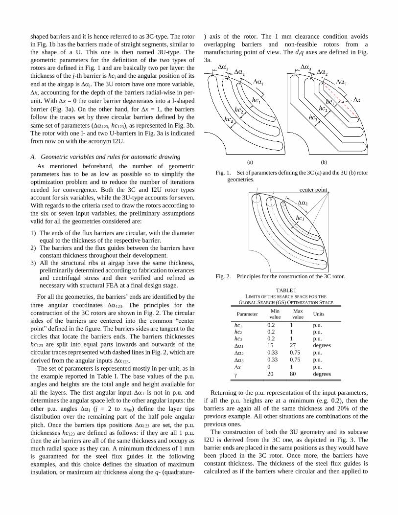
For all the geometries, the barriers’ ends are identified by the
three angular coordinates 123. The principles for the
construction of the 3C rotors are shown in Fig. 2. The circular
sides of the barriers are centered into the common “center
point” defined in the figure. The barriers sides are tangent to the
circles that locate the barriers ends. The barriers thicknesses
hc123 are split into equal parts inwards and outwards of the
circular traces represented with dashed lines in Fig. 2, which are
derived from the angular inputs 123.
The set of parameters is represented mostly in per-unit, as in
the example reported in Table I. The base values of the p.u.
angles and heights are the total angle and height available for
all the layers. The first angular input 1 is not in p.u. and
determines the angular space left to the other angular inputs: the
other p.u. angles j (j = 2 to nlay) define the layer tips
distribution over the remaining part of the half pole angular
pitch. Once the barriers tips positions are set, the p.u.
thicknesses hc123 are defined as follows: if they are all 1 p.u.
then the air barriers are all of the same thickness and occupy as
much radial space as they can. A minimum thickness of 1 mm
is guaranteed for the steel flux guides in the following
examples, and this choice defines the situation of maximum
insulation, or maximum air thickness along the q- (quadrature-
) axis of the rotor. The 1 mm clearance condition avoids
overlapping barriers and non-feasible rotors from a
manufacturing point of view. The d,q axes are defined in Fig.
3a.
(a) (b)
Fig. 1. Set of parameters defining the 3C (a) and the 3U (b) rotor
geometries.
Fig. 2. Principles for the construction of the 3C rotor.
TABLE I LIMITS OF THE SEARCH SPACE FOR THE
GLOBAL SEARCH (GS) OPTIMIZATION STAGE
Parameter Min value
Max value
Units
hc1 0.2 1 p.u.
hc2 0.2 1 p.u.
hc3 0.2 1 p.u.
1 15 27 degrees
2 0.33 0.75 p.u.
3 0.33 0.75 p.u.
x 0 1 p.u.
20 80 degrees
Returning to the p.u. representation of the input parameters,
if all the p.u. heights are at a minimum (e.g. 0.2), then the
barriers are again all of the same thickness and 20% of the
previous example. All other situations are combinations of the
previous ones.
The construction of both the 3U geometry and its subcase
I2U is derived from the 3C one, as depicted in Fig. 3. The
barrier ends are placed in the same positions as they would have
been placed in the 3C rotor. Once more, the barriers have
constant thickness. The thickness of the steel flux guides is
calculated as if the barriers where circular and then applied to
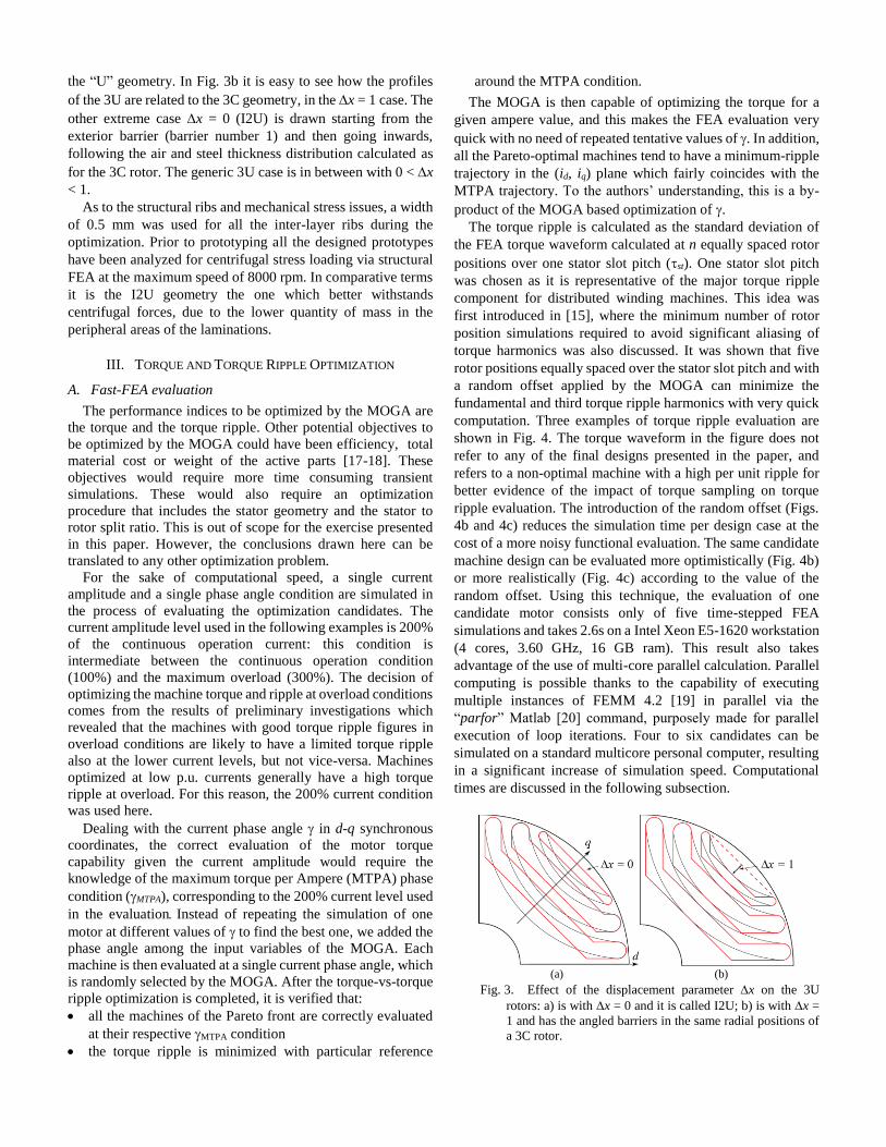
the “U” geometry. In Fig. 3b it is easy to see how the profiles
of the 3U are related to the 3C geometry, in the x = 1 case. The
other extreme case x = 0 (I2U) is drawn starting from the
exterior barrier (barrier number 1) and then going inwards,
following the air and steel thickness distribution calculated as
for the 3C rotor. The generic 3U case is in between with 0 < x
< 1.
As to the structural ribs and mechanical stress issues, a width
of 0.5 mm was used for all the inter-layer ribs during the
optimization. Prior to prototyping all the designed prototypes
have been analyzed for centrifugal stress loading via structural
FEA at the maximum speed of 8000 rpm. In comparative terms
it is the I2U geometry the one which better withstands
centrifugal forces, due to the lower quantity of mass in the
peripheral areas of the laminations.
III. TORQUE AND TORQUE RIPPLE OPTIMIZATION
A. Fast-FEA evaluation
The performance indices to be optimized by the MOGA are
the torque and the torque ripple. Other potential objectives to
be optimized by the MOGA could have been efficiency, total
material cost or weight of the active parts [17-18]. These
objectives would require more time consuming transient
simulations. These would also require an optimization
procedure that includes the stator geometry and the stator to
rotor split ratio. This is out of scope for the exercise presented
in this paper. However, the conclusions drawn here can be
translated to any other optimization problem.
For the sake of computational speed, a single current
amplitude and a single phase angle condition are simulated in
the process of evaluating the optimization candidates. The
current amplitude level used in the following examples is 200%
of the continuous operation current: this condition is
intermediate between the continuous operation condition
(100%) and the maximum overload (300%). The decision of
optimizing the machine torque and ripple at overload conditions
comes from the results of preliminary investigations which
revealed that the machines with good torque ripple figures in
overload conditions are likely to have a limited torque ripple
also at the lower current levels, but not vice-versa. Machines
optimized at low p.u. currents generally have a high torque
ripple at overload. For this reason, the 200% current condition
was used here.
Dealing with the current phase angle in d-q synchronous
coordinates, the correct evaluation of the motor torque
capability given the current amplitude would require the
knowledge of the maximum torque per Ampere (MTPA) phase
condition (MTPA), corresponding to the 200% current level used
in the evaluationInstead of repeating the simulation of one
motor at different values of to find the best one, we added the
phase angle among the input variables of the MOGA. Each
machine is then evaluated at a single current phase angle, which
is randomly selected by the MOGA. After the torque-vs-torque
ripple optimization is completed, it is verified that:
all the machines of the Pareto front are correctly evaluated
at their respective MTPA condition
the torque ripple is minimized with particular reference
around the MTPA condition.
The MOGA is then capable of optimizing the torque for a
given ampere value, and this makes the FEA evaluation very
quick with no need of repeated tentative values of . In addition,
all the Pareto-optimal machines tend to have a minimum-ripple
trajectory in the (id, iq) plane which fairly coincides with the
MTPA trajectory. To the authors’ understanding, this is a by-
product of the MOGA based optimization of .
The torque ripple is calculated as the standard deviation of
the FEA torque waveform calculated at n equally spaced rotor
positions over one stator slot pitch (st). One stator slot pitch
was chosen as it is representative of the major torque ripple
component for distributed winding machines. This idea was
first introduced in [15], where the minimum number of rotor
position simulations required to avoid significant aliasing of
torque harmonics was also discussed. It was shown that five
rotor positions equally spaced over the stator slot pitch and with
a random offset applied by the MOGA can minimize the
fundamental and third torque ripple harmonics with very quick
computation. Three examples of torque ripple evaluation are
shown in Fig. 4. The torque waveform in the figure does not
refer to any of the final designs presented in the paper, and
refers to a non-optimal machine with a high per unit ripple for
better evidence of the impact of torque sampling on torque
ripple evaluation. The introduction of the random offset (Figs.
4b and 4c) reduces the simulation time per design case at the
cost of a more noisy functional evaluation. The same candidate
machine design can be evaluated more optimistically (Fig. 4b)
or more realistically (Fig. 4c) according to the value of the
random offset. Using this technique, the evaluation of one
candidate motor consists only of five time-stepped FEA
simulations and takes 2.6s on a Intel Xeon E5-1620 workstation
(4 cores, 3.60 GHz, 16 GB ram). This result also takes
advantage of the use of multi-core parallel calculation. Parallel
computing is possible thanks to the capability of executing
multiple instances of FEMM 4.2 [19] in parallel via the
“parfor” Matlab [20] command, purposely made for parallel
execution of loop iterations. Four to six candidates can be
simulated on a standard multicore personal computer, resulting
in a significant increase of simulation speed. Computational
times are discussed in the following subsection.
(a) (b)
Fig. 3. Effect of the displacement parameter x on the 3U
rotors: a) is with x = 0 and it is called I2U; b) is with x =
1 and has the angled barriers in the same radial positions of
a 3C rotor.
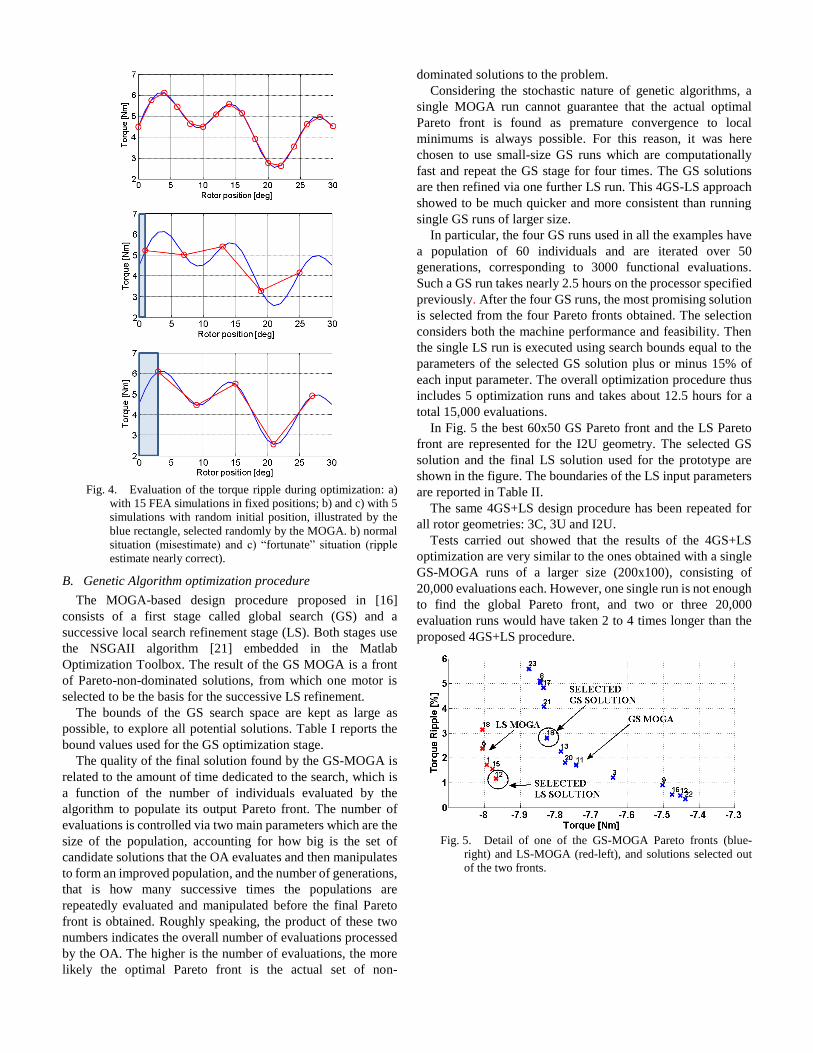
Fig. 4. Evaluation of the torque ripple during optimization: a)
with 15 FEA simulations in fixed positions; b) and c) with 5
simulations with random initial position, illustrated by the
blue rectangle, selected randomly by the MOGA. b) normal
situation (misestimate) and c) “fortunate” situation (ripple
estimate nearly correct).
B. Genetic Algorithm optimization procedure
The MOGA-based design procedure proposed in [16]
consists of a first stage called global search (GS) and a
successive local search refinement stage (LS). Both stages use
the NSGAII algorithm [21] embedded in the Matlab
Optimization Toolbox. The result of the GS MOGA is a front
of Pareto-non-dominated solutions, from which one motor is
selected to be the basis for the successive LS refinement.
The bounds of the GS search space are kept as large as
possible, to explore all potential solutions. Table I reports the
bound values used for the GS optimization stage.
The quality of the final solution found by the GS-MOGA is
related to the amount of time dedicated to the search, which is
a function of the number of individuals evaluated by the
algorithm to populate its output Pareto front. The number of
evaluations is controlled via two main parameters which are the
size of the population, accounting for how big is the set of
candidate solutions that the OA evaluates and then manipulates
to form an improved population, and the number of generations,
that is how many successive times the populations are
repeatedly evaluated and manipulated before the final Pareto
front is obtained. Roughly speaking, the product of these two
numbers indicates the overall number of evaluations processed
by the OA. The higher is the number of evaluations, the more
likely the optimal Pareto front is the actual set of non-
dominated solutions to the problem.
Considering the stochastic nature of genetic algorithms, a
single MOGA run cannot guarantee that the actual optimal
Pareto front is found as premature convergence to local
minimums is always possible. For this reason, it was here
chosen to use small-size GS runs which are computationally
fast and repeat the GS stage for four times. The GS solutions
are then refined via one further LS run. This 4GS-LS approach
showed to be much quicker and more consistent than running
single GS runs of larger size.
In particular, the four GS runs used in all the examples have
a population of 60 individuals and are iterated over 50
generations, corresponding to 3000 functional evaluations.
Such a GS run takes nearly 2.5 hours on the processor specified
previously. After the four GS runs, the most promising solution
is selected from the four Pareto fronts obtained. The selection
considers both the machine performance and feasibility. Then
the single LS run is executed using search bounds equal to the
parameters of the selected GS solution plus or minus 15% of
each input parameter. The overall optimization procedure thus
includes 5 optimization runs and takes about 12.5 hours for a
total 15,000 evaluations.
In Fig. 5 the best 60x50 GS Pareto front and the LS Pareto
front are represented for the I2U geometry. The selected GS
solution and the final LS solution used for the prototype are
shown in the figure. The boundaries of the LS input parameters
are reported in Table II.
The same 4GS+LS design procedure has been repeated for
all rotor geometries: 3C, 3U and I2U.
Tests carried out showed that the results of the 4GS+LS
optimization are very similar to the ones obtained with a single
GS-MOGA runs of a larger size (200x100), consisting of
20,000 evaluations each. However, one single run is not enough
to find the global Pareto front, and two or three 20,000
evaluation runs would have taken 2 to 4 times longer than the
proposed 4GS+LS procedure.
Fig. 5. Detail of one of the GS-MOGA Pareto fronts (blue-
right) and LS-MOGA (red-left), and solutions selected out
of the two fronts.
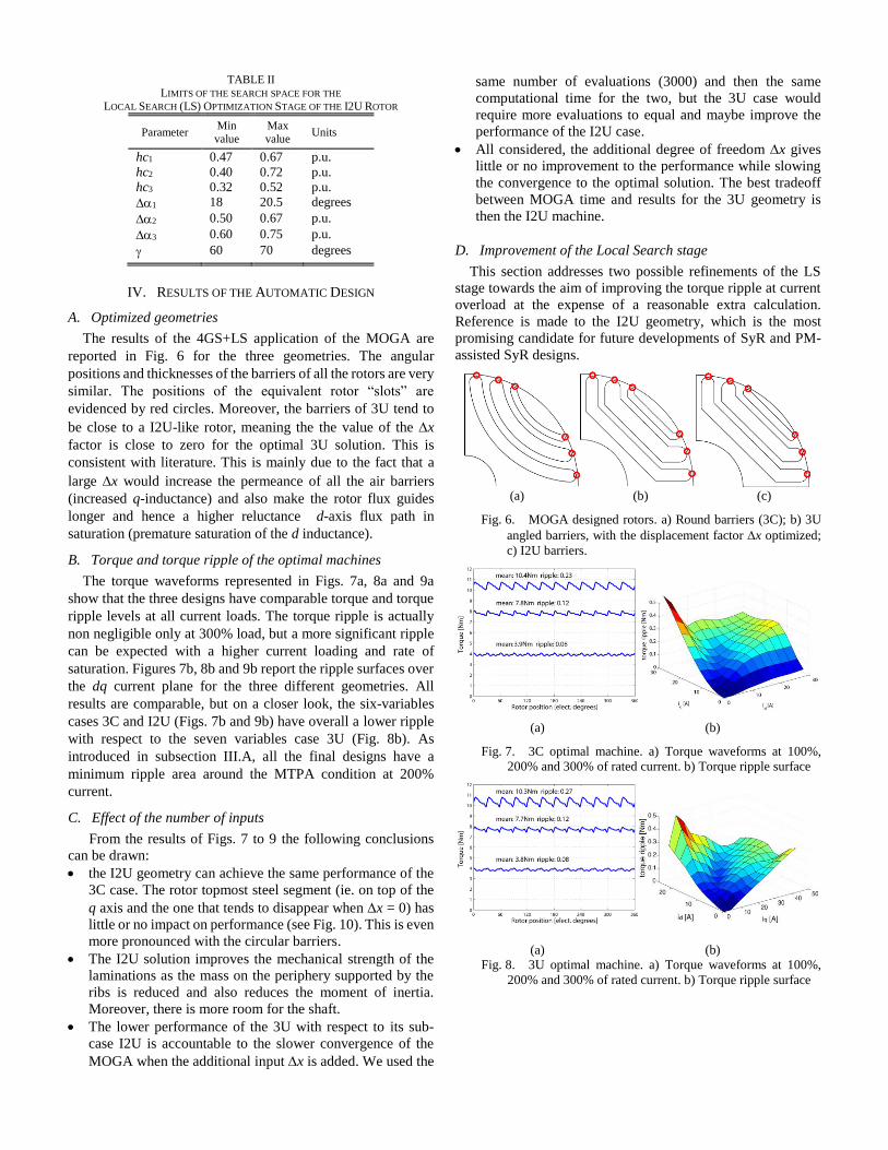
TABLE II
LIMITS OF THE SEARCH SPACE FOR THE LOCAL SEARCH (LS) OPTIMIZATION STAGE OF THE I2U ROTOR
Parameter Min value
Max value
Units
hc1 0.47 0.67 p.u.
hc2 0.40 0.72 p.u.
hc3 0.32 0.52 p.u.
1 18 20.5 degrees
2 0.50 0.67 p.u.
3 0.60 0.75 p.u.
60 70 degrees
IV. RESULTS OF THE AUTOMATIC DESIGN
A. Optimized geometries
The results of the 4GS+LS application of the MOGA are
reported in Fig. 6 for the three geometries. The angular
positions and thicknesses of the barriers of all the rotors are very
similar. The positions of the equivalent rotor “slots” are
evidenced by red circles. Moreover, the barriers of 3U tend to
be close to a I2U-like rotor, meaning the the value of the x
factor is close to zero for the optimal 3U solution. This is
consistent with literature. This is mainly due to the fact that a
large x would increase the permeance of all the air barriers
(increased q-inductance) and also make the rotor flux guides
longer and hence a higher reluctance d-axis flux path in
saturation (premature saturation of the d inductance).
B. Torque and torque ripple of the optimal machines
The torque waveforms represented in Figs. 7a, 8a and 9a
show that the three designs have comparable torque and torque
ripple levels at all current loads. The torque ripple is actually
non negligible only at 300% load, but a more significant ripple
can be expected with a higher current loading and rate of
saturation. Figures 7b, 8b and 9b report the ripple surfaces over
the dq current plane for the three different geometries. All
results are comparable, but on a closer look, the six-variables
cases 3C and I2U (Figs. 7b and 9b) have overall a lower ripple
with respect to the seven variables case 3U (Fig. 8b). As
introduced in subsection III.A, all the final designs have a
minimum ripple area around the MTPA condition at 200%
current.
C. Effect of the number of inputs
From the results of Figs. 7 to 9 the following conclusions
can be drawn:
the I2U geometry can achieve the same performance of the
3C case. The rotor topmost steel segment (ie. on top of the
q axis and the one that tends to disappear when x = 0) has
little or no impact on performance (see Fig. 10). This is even
more pronounced with the circular barriers.
The I2U solution improves the mechanical strength of the
laminations as the mass on the periphery supported by the
ribs is reduced and also reduces the moment of inertia.
Moreover, there is more room for the shaft.
The lower performance of the 3U with respect to its sub-
case I2U is accountable to the slower convergence of the
MOGA when the additional input x is added. We used the
same number of evaluations (3000) and then the same
computational time for the two, but the 3U case would
require more evaluations to equal and maybe improve the
performance of the I2U case.
All considered, the additional degree of freedom x gives
little or no improvement to the performance while slowing
the convergence to the optimal solution. The best tradeoff
between MOGA time and results for the 3U geometry is
then the I2U machine.
D. Improvement of the Local Search stage
This section addresses two possible refinements of the LS
stage towards the aim of improving the torque ripple at current
overload at the expense of a reasonable extra calculation.
Reference is made to the I2U geometry, which is the most
promising candidate for future developments of SyR and PM-
assisted SyR designs.
(a) (b) (c)
Fig. 6. MOGA designed rotors. a) Round barriers (3C); b) 3U
angled barriers, with the displacement factor x optimized;
c) I2U barriers.
(a) (b)
Fig. 7. 3C optimal machine. a) Torque waveforms at 100%,
200% and 300% of rated current. b) Torque ripple surface
(a) (b) Fig. 8. 3U optimal machine. a) Torque waveforms at 100%,
200% and 300% of rated current. b) Torque ripple surface
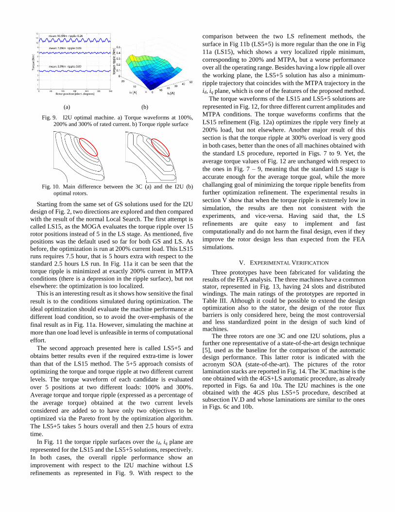
(a) (b)
Fig. 9. I2U optimal machine. a) Torque waveforms at 100%,
200% and 300% of rated current. b) Torque ripple surface
Fig. 10. Main difference between the 3C (a) and the I2U (b)
optimal rotors.
Starting from the same set of GS solutions used for the I2U
design of Fig. 2, two directions are explored and then compared
with the result of the normal Local Search. The first attempt is
called LS15, as the MOGA evaluates the torque ripple over 15
rotor positions instead of 5 in the LS stage. As mentioned, five
positions was the default used so far for both GS and LS. As
before, the optimization is run at 200% current load. This LS15
runs requires 7.5 hour, that is 5 hours extra with respect to the
standard 2.5 hours LS run. In Fig. 11a it can be seen that the
torque ripple is minimized at exactly 200% current in MTPA
conditions (there is a depression in the ripple surface), but not
elsewhere: the optimization is too localized.
This is an interesting result as it shows how sensitive the final
result is to the conditions simulated during optimization. The
ideal optimization should evaluate the machine performance at
different load condition, so to avoid the over-emphasis of the
final result as in Fig. 11a. However, simulating the machine at
more than one load level is unfeasible in terms of computational
effort.
The second approach presented here is called LS5+5 and
obtains better results even if the required extra-time is lower
than that of the LS15 method. The 5+5 approach consists of
optimizing the torque and torque ripple at two different current
levels. The torque waveform of each candidate is evaluated
over 5 positions at two different loads: 100% and 300%.
Average torque and torque ripple (expressed as a percentage of
the average torque) obtained at the two current levels
considered are added so to have only two objectives to be
optimized via the Pareto front by the optimization algorithm.
The LS5+5 takes 5 hours overall and then 2.5 hours of extra
time.
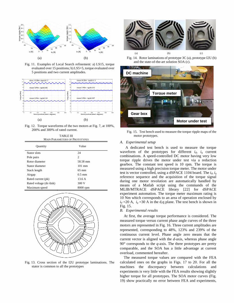
In Fig. 11 the torque ripple surfaces over the id, iq plane are
represented for the LS15 and the LS5+5 solutions, respectively.
In both cases, the overall ripple performance show an
improvement with respect to the I2U machine without LS
refinements as represented in Fig. 9. With respect to the
comparison between the two LS refinement methods, the
surface in Fig 11b (LS5+5) is more regular than the one in Fig
11a (LS15), which shows a very localized ripple minimum,
corresponding to 200% and MTPA, but a worse performance
over all the operating range. Besides having a low ripple all over
the working plane, the LS5+5 solution has also a minimum-
ripple trajectory that coincides with the MTPA trajectory in the
id, iq plane, which is one of the features of the proposed method.
The torque waveforms of the LS15 and LS5+5 solutions are
represented in Fig. 12, for three different current amplitudes and
MTPA conditions. The torque waveforms confirms that the
LS15 refinement (Fig. 12a) optimizes the ripple very finely at
200% load, but not elsewhere. Another major result of this
section is that the torque ripple at 300% overload is very good
in both cases, better than the ones of all machines obtained with
the standard LS procedure, reported in Figs. 7 to 9. Yet, the
average torque values of Fig. 12 are unchanged with respect to
the ones in Fig. 7 – 9, meaning that the standard LS stage is
accurate enough for the average torque goal, while the more
challanging goal of minimizing the torque ripple benefits from
further optimization refinement. The experimental results in
section V show that when the torque ripple is extremely low in
simulation, the results are then not consistent with the
experiments, and vice-versa. Having said that, the LS
refinements are quite easy to implement and fast
computationally and do not harm the final design, even if they
improve the rotor design less than expected from the FEA
simulations.
V. EXPERIMENTAL VERIFICATION
Three prototypes have been fabricated for validating the results of the FEA analysis. The three machines have a common stator, represented in Fig. 13, having 24 slots and distributed windings. The main ratings of the prototypes are reported in Table III. Although it could be possible to extend the design optimization also to the stator, the design of the rotor flux barriers is only considered here, being the most controversial and less standardized point in the design of such kind of machines.
The three rotors are one 3C and one I2U solutions, plus a further one representative of a state-of-the-art design technique [5], used as the baseline for the comparison of the automatic design performance. This latter rotor is indicated with the acronym SOA (state-of-the-art). The pictures of the rotor lamination stacks are reported in Fig. 14. The 3C machine is the one obtained with the 4GS+LS automatic procedure, as already reported in Figs. 6a and 10a. The I2U machines is the one obtained with the 4GS plus LS5+5 procedure, described at subsection IV.D and whose laminations are similar to the ones in Figs. 6c and 10b.
(a) (b)
Fig. 11. Examples of Local Search refinement: a) LS15, torque
evaluated over 15 positions; b) LS5+5, torque evaluated over
5 positions and two current amplitudes.
(a) (b)
Fig. 12. Torque waveforms of the two motors at Fig. 7, at 100%,
200% and 300% of rated current.
TABLE III MAIN PARAMETERS OF PROTOTYPES
Quantity Value
Stator slots 24
Pole pairs 2
Rotor diameter 58.58 mm
Stator diameter 101 mm
Stack length 65 mm
Airgap 0.5 mm
Rated current (pk) 13.6 A
Rated voltage (dc-link) 300 V
Maximum speed 8000 rpm
Fig. 13. Cross section of the I2U prototype laminations. The
stator is common to all the prototypes
(a) (b) (c)
Fig. 14. Rotor laminations of prototype 3C (a), prototype I2U (b)
and the state-of-the-art solution SOA (c).
Fig. 15. Test bench used to measure the torque ripple maps of the
motor prototypes.
A. Experimental setup
A dedicated test bench is used to measure the torque waveform of the prototypes for different id, iq current combinations. A speed-controlled DC motor having very low torque ripple drives the motor under test via a reduction gearbox. The constant test speed is 10 rpm. The torque is measured using a high precision torque meter. The motor under test is vector controlled, using a dSPACE 1104 board. The id, iq reference sequence and the acquisition of the torque signal during one motor revolution are automatically handled by means of a Matlab script using the commands of the MLIB/MTRACE dSPACE library [22] for dSPACE experiment automation. The torque meter maximum rating is 10 Nm which corresponds to an area of operation enclosed by id =20 A, iq =30 A in the d,q plane. The test bench is shown in Fig. 15. B. Experimental results
At first, the average torque performance is considered. The
measured torque versus current phase angle curves of the three
motors are represented in Fig. 16. Three current amplitudes are
represented, corresponding to 48%, 123% and 239% of the
continuous current level. Phase angle zero means that the
current vector is aligned with the d-axis, whereas phase angle
90° corresponds to the q-axis. The three prototypes are pretty
comparable, and the SOA has a little advantage at current
overload, commented hereafter.
The measured torque values are compared with the FEA
calculated ones on the graphs in Figs. 17 to 20. For all the
machines the discrepancy between calculations and
experiments is very little with the FEA results showing slightly
higher torque for all prototypes. The SOA motor curves (Fig.
19) show practically no error between FEA and experiments,
Motor under test
DC machine
Torque meter
Gear box
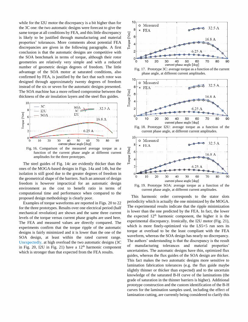
while for the I2U motor the discrepancy is a bit higher than for
the 3C one: the two automatic designs were forecast to give the
same torque at all conditions by FEA, and this little discrepancy
is likely to be justified through manufacturing and material
properties’ tolerances. More comments about potential FEA
discrepancies are given in the following paragraphs. A first
conclusion is that the automatic designs are competitive with
the SOA benchmark in terms of torque, although their rotor
geometries are relatively very simple and with a reduced
number of geometric design degrees of freedom. The little
advantage of the SOA motor at saturated conditions, also
confirmed by FEA, is justified by the fact that such rotor was
designed through approximately twenty degrees of freedom
instead of the six or seven for the automatic designs presented.
The SOA machine has a more refined compromise between the
thickness of the air insulation layers and the steel flux guides.
Fig. 16. Comparison of the measured average torque as a
function of the current phase angle at different current
amplitudes for the three prototypes.
The steel guides of Fig. 14c are evidently thicker than the
ones of the MOGA-based designs in Figs. 14a and 14b, but the
isolation is still good due to the greater degrees of freedom in
the geometrical shape of the barriers. Such an amount of design
freedom is however impractical for an automatic design
environment as the cost to benefit ratio in terms of
computational time and performance when compared to the
proposed design methodology is clearly poor.
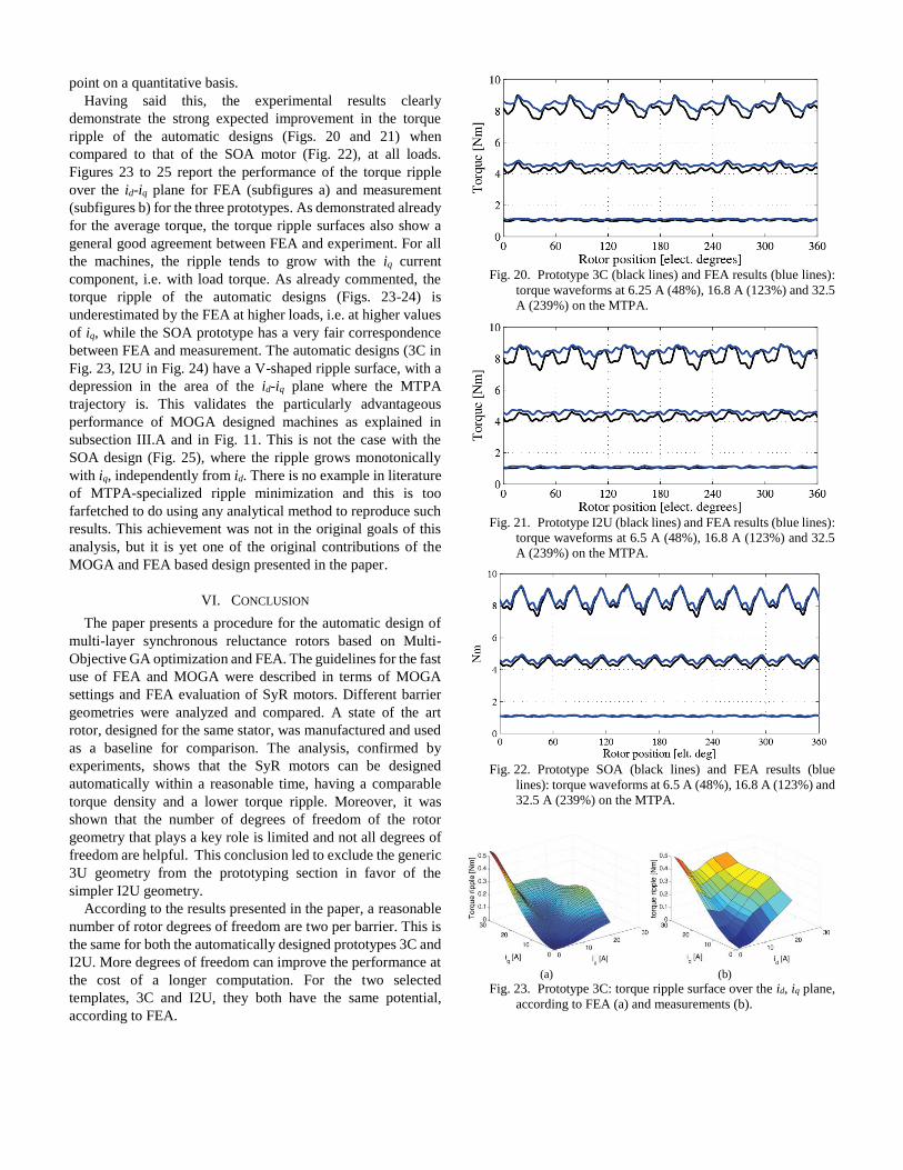
Examples of torque waveforms are reported in Figs. 20 to 22
for the three prototypes. Results over one electrical period (half
mechanical revolution) are shown and the same three current
levels of the torque versus current phase graphs are used here.
The FEA and measured values are directly compared. The
experiments confirm that the torque ripple of the automatic
designs is fairly minimized and it is lower than the one of the
SOA design, at least within the rated current range.
Unexpectedly, at high overload the two automatic designs (3C
in Fig. 20, I2U in Fig. 21) have a 12th harmonic component
which is stronger than that expected from the FEA results.
Fig. 17. Prototype 3C: average torque as a function of the current
phase angle, at different current amplitudes.
Fig. 18. Prototype I2U: average torque as a function of the
current phase angle, at different current amplitudes.
Fig. 19. Prototype SOA: average torque as a function of the
current phase angle, at different current amplitudes.
This harmonic order corresponds to the stator slots
periodicity which is actually the one minimized by the MOGA.
The experimental results indicate that the ripple minimization
is lower than the one predicted by the FEA. In fact, the lower
the expected 12th harmonic component, the higher it is the
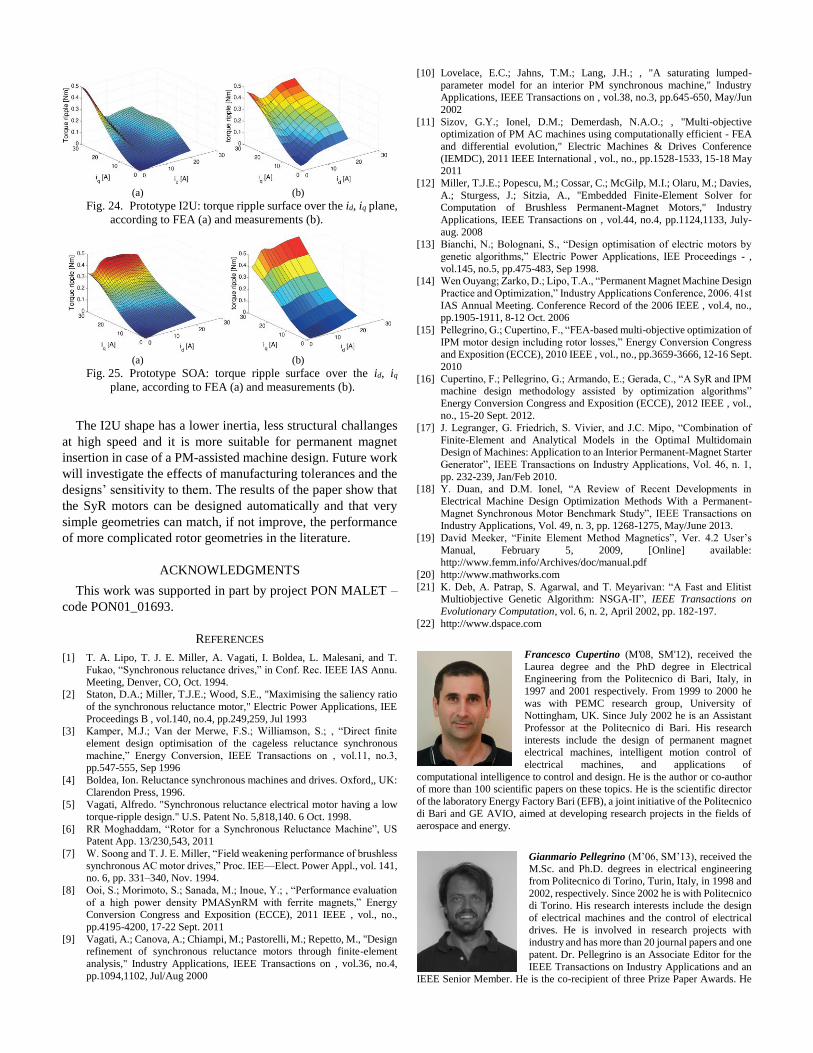
experimental discrepancy. Ironically, the I2U motor (Fig. 21),
which is more finely-optimized via the LS5+5 run sees its
torque at overload to be the least compliant with the FEA
waveform, whereas the SOA design has nearly no discrepancy.
The authors’ understanding is that the discrepancy is the result
of manufacturing tolerances and material properties’
uncertainties. The automatic designs have thin, optimized flux
guides, whereas the flux guides of the SOA design are thicker.
This fact makes the two automatic designs more sensitive to
lamination fabrication tolerances (e.g. the flux guide maybe
slightly thinner or thicker than expected) and to the uncertain
knowledge of the saturated B-H curve of the laminations (the
grade of saturation in the thinner barriers is higher). Additional
prototype construction and the custom identification of the B-H
curves for the lamination samples used, including the effect of
lamination cutting, are currently being considered to clarify this
point on a quantitative basis.
Having said this, the experimental results clearly
demonstrate the strong expected improvement in the torque
ripple of the automatic designs (Figs. 20 and 21) when
compared to that of the SOA motor (Fig. 22), at all loads.
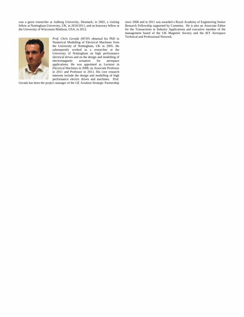
Figures 23 to 25 report the performance of the torque ripple
over the id-iq plane for FEA (subfigures a) and measurement
(subfigures b) for the three prototypes. As demonstrated already
for the average torque, the torque ripple surfaces also show a
general good agreement between FEA and experiment. For all
the machines, the ripple tends to grow with the iq current
component, i.e. with load torque. As already commented, the
torque ripple of the automatic designs (Figs. 23-24) is
underestimated by the FEA at higher loads, i.e. at higher values
of iq, while the SOA prototype has a very fair correspondence
between FEA and measurement. The automatic designs (3C in
Fig. 23, I2U in Fig. 24) have a V-shaped ripple surface, with a
depression in the area of the id-iq plane where the MTPA
trajectory is. This validates the particularly advantageous
performance of MOGA designed machines as explained in
subsection III.A and in Fig. 11. This is not the case with the
SOA design (Fig. 25), where the ripple grows monotonically
with iq, independently from id. There is no example in literature
of MTPA-specialized ripple minimization and this is too
farfetched to do using any analytical method to reproduce such
results. This achievement was not in the original goals of this
analysis, but it is yet one of the original contributions of the
MOGA and FEA based design presented in the paper.
VI. CONCLUSION
The paper presents a procedure for the automatic design of
multi-layer synchronous reluctance rotors based on Multi-
Objective GA optimization and FEA. The guidelines for the fast
use of FEA and MOGA were described in terms of MOGA
settings and FEA evaluation of SyR motors. Different barrier
geometries were analyzed and compared. A state of the art
rotor, designed for the same stator, was manufactured and used
as a baseline for comparison. The analysis, confirmed by
experiments, shows that the SyR motors can be designed
automatically within a reasonable time, having a comparable
torque density and a lower torque ripple. Moreover, it was
shown that the number of degrees of freedom of the rotor
geometry that plays a key role is limited and not all degrees of
freedom are helpful. This conclusion led to exclude the generic
3U geometry from the prototyping section in favor of the
simpler I2U geometry.
According to the results presented in the paper, a reasonable
number of rotor degrees of freedom are two per barrier. This is
the same for both the automatically designed prototypes 3C and
I2U. More degrees of freedom can improve the performance at
the cost of a longer computation. For the two selected
templates, 3C and I2U, they both have the same potential,
according to FEA.
Fig. 20. Prototype 3C (black lines) and FEA results (blue lines):
torque waveforms at 6.25 A (48%), 16.8 A (123%) and 32.5
A (239%) on the MTPA.
Fig. 21. Prototype I2U (black lines) and FEA results (blue lines):
torque waveforms at 6.5 A (48%), 16.8 A (123%) and 32.5
A (239%) on the MTPA.
Fig. 22. Prototype SOA (black lines) and FEA results (blue
lines): torque waveforms at 6.5 A (48%), 16.8 A (123%) and
32.5 A (239%) on the MTPA.
(a) (b)
Fig. 23. Prototype 3C: torque ripple surface over the id, iq plane,
according to FEA (a) and measurements (b).
(a) (b)
Fig. 24. Prototype I2U: torque ripple surface over the id, iq plane,
according to FEA (a) and measurements (b).
(a) (b)
Fig. 25. Prototype SOA: torque ripple surface over the id, iq
plane, according to FEA (a) and measurements (b).
The I2U shape has a lower inertia, less structural challanges
at high speed and it is more suitable for permanent magnet
insertion in case of a PM-assisted machine design. Future work
will investigate the effects of manufacturing tolerances and the
designs’ sensitivity to them. The results of the paper show that
the SyR motors can be designed automatically and that very
simple geometries can match, if not improve, the performance
of more complicated rotor geometries in the literature.
ACKNOWLEDGMENTS
This work was supported in part by project PON MALET –
code PON01_01693.
REFERENCES
[1] T. A. Lipo, T. J. E. Miller, A. Vagati, I. Boldea, L. Malesani, and T.
Fukao, “Synchronous reluctance drives,” in Conf. Rec. IEEE IAS Annu.
Meeting, Denver, CO, Oct. 1994. [2] Staton, D.A.; Miller, T.J.E.; Wood, S.E., "Maximising the saliency ratio
of the synchronous reluctance motor," Electric Power Applications, IEE
Proceedings B , vol.140, no.4, pp.249,259, Jul 1993 [3] Kamper, M.J.; Van der Merwe, F.S.; Williamson, S.; , “Direct finite
element design optimisation of the cageless reluctance synchronous
machine,” Energy Conversion, IEEE Transactions on , vol.11, no.3, pp.547-555, Sep 1996
[4] Boldea, Ion. Reluctance synchronous machines and drives. Oxford,, UK:
Clarendon Press, 1996. [5] Vagati, Alfredo. "Synchronous reluctance electrical motor having a low
torque-ripple design." U.S. Patent No. 5,818,140. 6 Oct. 1998.
[6] RR Moghaddam, “Rotor for a Synchronous Reluctance Machine”, US Patent App. 13/230,543, 2011
[7] W. Soong and T. J. E. Miller, “Field weakening performance of brushless
synchronous AC motor drives,” Proc. IEE—Elect. Power Appl., vol. 141, no. 6, pp. 331–340, Nov. 1994.
[8] Ooi, S.; Morimoto, S.; Sanada, M.; Inoue, Y.; , “Performance evaluation
of a high power density PMASynRM with ferrite magnets,” Energy Conversion Congress and Exposition (ECCE), 2011 IEEE , vol., no.,
pp.4195-4200, 17-22 Sept. 2011
[9] Vagati, A.; Canova, A.; Chiampi, M.; Pastorelli, M.; Repetto, M., "Design refinement of synchronous reluctance motors through finite-element
analysis," Industry Applications, IEEE Transactions on , vol.36, no.4,
pp.1094,1102, Jul/Aug 2000
[10] Lovelace, E.C.; Jahns, T.M.; Lang, J.H.; , "A saturating lumped-
parameter model for an interior PM synchronous machine," Industry Applications, IEEE Transactions on , vol.38, no.3, pp.645-650, May/Jun
2002
[11] Sizov, G.Y.; Ionel, D.M.; Demerdash, N.A.O.; , "Multi-objective optimization of PM AC machines using computationally efficient - FEA
and differential evolution," Electric Machines & Drives Conference
(IEMDC), 2011 IEEE International , vol., no., pp.1528-1533, 15-18 May 2011
[12] Miller, T.J.E.; Popescu, M.; Cossar, C.; McGilp, M.I.; Olaru, M.; Davies,
A.; Sturgess, J.; Sitzia, A., "Embedded Finite-Element Solver for Computation of Brushless Permanent-Magnet Motors," Industry
Applications, IEEE Transactions on , vol.44, no.4, pp.1124,1133, July-
aug. 2008 [13] Bianchi, N.; Bolognani, S., “Design optimisation of electric motors by
genetic algorithms,” Electric Power Applications, IEE Proceedings - ,
vol.145, no.5, pp.475-483, Sep 1998. [14] Wen Ouyang; Zarko, D.; Lipo, T.A., “Permanent Magnet Machine Design
Practice and Optimization,” Industry Applications Conference, 2006. 41st
IAS Annual Meeting. Conference Record of the 2006 IEEE , vol.4, no., pp.1905-1911, 8-12 Oct. 2006
[15] Pellegrino, G.; Cupertino, F., “FEA-based multi-objective optimization of
IPM motor design including rotor losses,” Energy Conversion Congress and Exposition (ECCE), 2010 IEEE , vol., no., pp.3659-3666, 12-16 Sept.
2010
[16] Cupertino, F.; Pellegrino, G.; Armando, E.; Gerada, C., “A SyR and IPM machine design methodology assisted by optimization algorithms”
Energy Conversion Congress and Exposition (ECCE), 2012 IEEE , vol., no., 15-20 Sept. 2012.
[17] J. Legranger, G. Friedrich, S. Vivier, and J.C. Mipo, “Combination of
Finite-Element and Analytical Models in the Optimal Multidomain Design of Machines: Application to an Interior Permanent-Magnet Starter
Generator”, IEEE Transactions on Industry Applications, Vol. 46, n. 1,
pp. 232-239, Jan/Feb 2010. [18] Y. Duan, and D.M. Ionel, “A Review of Recent Developments in
Electrical Machine Design Optimization Methods With a Permanent-
Magnet Synchronous Motor Benchmark Study”, IEEE Transactions on Industry Applications, Vol. 49, n. 3, pp. 1268-1275, May/June 2013.
[19] David Meeker, “Finite Element Method Magnetics”, Ver. 4.2 User’s
Manual, February 5, 2009, [Online] available: http://www.femm.info/Archives/doc/manual.pdf
[20] http://www.mathworks.com
[21] K. Deb, A. Patrap, S. Agarwal, and T. Meyarivan: “A Fast and Elitist Multiobjective Genetic Algorithm: NSGA-II”, IEEE Transactions on
Evolutionary Computation, vol. 6, n. 2, April 2002, pp. 182-197.
[22] http://www.dspace.com
Francesco Cupertino (M'08, SM'12), received the
Laurea degree and the PhD degree in Electrical Engineering from the Politecnico di Bari, Italy, in
1997 and 2001 respectively. From 1999 to 2000 he
was with PEMC research group, University of Nottingham, UK. Since July 2002 he is an Assistant
Professor at the Politecnico di Bari. His research
interests include the design of permanent magnet electrical machines, intelligent motion control of
electrical machines, and applications of
computational intelligence to control and design. He is the author or co-author of more than 100 scientific papers on these topics. He is the scientific director
of the laboratory Energy Factory Bari (EFB), a joint initiative of the Politecnico
di Bari and GE AVIO, aimed at developing research projects in the fields of aerospace and energy.
Gianmario Pellegrino (M’06, SM’13), received the M.Sc. and Ph.D. degrees in electrical engineering
from Politecnico di Torino, Turin, Italy, in 1998 and
2002, respectively. Since 2002 he is with Politecnico di Torino. His research interests include the design
of electrical machines and the control of electrical
drives. He is involved in research projects with industry and has more than 20 journal papers and one
patent. Dr. Pellegrino is an Associate Editor for the
IEEE Transactions on Industry Applications and an IEEE Senior Member. He is the co-recipient of three Prize Paper Awards. He
was a guest researcher at Aalborg University, Denmark, in 2002, a visiting
fellow at Nottingham University, UK, in 2010/2011, and an honorary fellow at the University of Wisconsin-Madison, USA, in 2013.
Prof. Chris Gerada (M’05) obtained his PhD in Numerical Modelling of Electrical Machines from
the University of Nottingham, UK in 2005. He
subsequently worked as a researcher at the University of Nottingham on high performance
electrical drives and on the design and modelling of
electromagnetic actuators for aerospace applications. He was appointed as Lecturer in
Electrical Machines in 2008, an Associate Professor
in 2011 and Professor in 2013. His core research interests include the design and modelling of high
performance electric drives and machines. Prof.
Gerada has been the project manager of the GE Aviation Strategic Partnership
since 2006 and in 2011 was awarded a Royal Academy of Engineering Senior
Research Fellowship supported by Cummins. He is also an Associate Editor for the Transactions in Industry Applications and executive member of the
management board of the UK Magnetic Society and the IET Aerospace
Technical and Professional Network.