Embed Size (px)
Citation preview

Technical Manual - Part 2Installation and cabling instructions
For all Online Components and Offline-wallreader
Intelligent Access Control


Notes on the Instructions for Installation and Connection The documentation is for authorized, appropriately qualified persons responsible for the installation of the devices described in the documentation.
Additional information, such as notes on the operation, is framed and marked with .
Relevant information and instructions concerning your safety are marked by and must be observed. Noncompliance may lead to severe injuries or even death caused by electric shock.
The devices described in the documentation comply with the electrotechnical EN and CE standards effective at the time of printing. Device modifications are not permitted. All technical information herein is accurate at the time of printing. It is, however, not to be deemed in any way to be a specific warranty of certain characteristics.
The devices described in the documentation may only run on electrical installations that correspond to valid EN standards, e.g. DIN VDE 0100. To ensure malfunction-free operation, installation must be performed according to the rules of the TN-S-System, which means separate neutral and ground wires.


Contents i
Contents
1 Instructions for Installation and Connection of the IR PegaSys Controller 1
1.1 Introduction ....................................................................................................................................... 1 1.2 Function ............................................................................................................................................. 1 1.3 Electrical Cabling................................................................................................................................ 5 1.4 Connecting Validation Terminals ....................................................................................................... 8 1.5 Initial Operation ................................................................................................................................. 9 1.6 Technical Data ................................................................................................................................. 12
2 Instructions for Installation and Connection of the IR 712 Validation Terminal 15
2.1 Introduction ..................................................................................................................................... 15 2.2 Disposal ........................................................................................................................................... 15 2.3 IR 712: Function ............................................................................................................................... 15 2.4 IR 712: Installation ........................................................................................................................... 17 2.5 IR 712: Operation ............................................................................................................................ 21 2.6 Maintenance .................................................................................................................................... 22 2.7 Janitorial .......................................................................................................................................... 22 2.8 Technical Data ................................................................................................................................. 23
3 Instructions for Installation and Connection of the IR 700 W02 Validation Terminal 27
3.1 Introduction ..................................................................................................................................... 27 3.2 IR 700 W02: Function ...................................................................................................................... 27 3.3 IR 700 W02: Components ................................................................................................................ 28 3.4 IR 700 W02: Installation .................................................................................................................. 28 3.5 IR 700 W02: Operation .................................................................................................................... 33 3.6 Maintenance .................................................................................................................................... 35 3.7 Janitorial .......................................................................................................................................... 35 3.8 Spare Parts ....................................................................................................................................... 35 3.9 Technical Data ................................................................................................................................. 35
4 Instructions for Installation and Connection of the PegaSys W02 Wall Reader 39
4.1 Introduction ..................................................................................................................................... 39 4.2 W02 Wall Reader: Function ............................................................................................................. 39 4.3 W02 Wall Reader: Components ...................................................................................................... 40 4.4 W02 Wall Reader: Installation and Initial Operation ....................................................................... 40 4.5 Door Opening with RFID Identification Media ................................................................................ 45 4.6 Maintenance .................................................................................................................................... 45 4.7 Janitorial .......................................................................................................................................... 45 4.8 Spare Parts ....................................................................................................................................... 45 4.9 Technical Data ................................................................................................................................. 46
5 Index 47


Installation Instructions for PegaSys Controller


1
1 Instructions for Installation and Connection of the IR PegaSys Controller
1.1 Introduction
1.1.1 Validity of the documentation The documentation applies for PegaSys controllers with software versions ≥ 3.01. It contains information on installation, connection, and initial operation.
1.1.2 Intended use PegaSys controllers control devices, such as validation terminals of the IR 7xx series and switch electric door openers up to 30 V 2 A. The device is designed for fixed installation in dry rooms. Any other use is not in accordance with the intended purpose and is therefore not permitted.
1.1.3 Storage The device has to be stored in a dry place.
1.1.4 Disposal
After proper operation, the device is to be disposed of properly as electronic scrap. The owner can dispose of the device himself or return it to the supplier.
1.2 Function
This chapter provides information on functions of the PegaSys hardware components.
The PegaSys controller controls up to four validation terminals of the IR 700 W02 or IR 712 series. The connection is made via two RS 485 BUS interfaces. Two relays with potential-free contacts can be used for switching of electric door openers up to 30 V 2 A, making access control possible. A PC with the installed PegaSys 3000 software is required for the system operation.

2 Instructions for Installation and Connection of the IR PegaSys Controller
1.2.1 Function of the validation terminals Validation terminals read data from RFID identification media (RFID = Radio Frequency Identification) and write NetworkOnCard access (permissions for access control at offline terminals, such as PegaSys wall reader W02). Validation terminals with I/O board with 1 relay and 2 inputs switch, after reading the RFID identification medium, a relay with potential-free contacts. The relay can be used for control of electric door openers up to 30 V 2 A (see figure, door 2).
Figure: PegaSys system with door control.
Note, electric door opener
Please note: An electric door opener does not replace locking the door with a bolt. It is primarily intended for regular business hours, whereas the door is locked with a bolt at night.
1.2.2 Screw connectors The following is connected to the screw connectors: Screw connector Kl.1.: power supply, e.g. a transformer or a DC power unit. Screw connector Kl.4.: two bus cables with validation terminals. Screw connector Kl.5: door opener push-button with NO contacts at the inputs IN 2 and IN 4. Screw connector Kl.6: electric door opener with a power of 30V 2A. Screw connector Kl.7: electric door opener with a power of 30V 2A. Screw connector Kl.8.: RS 232 dialog device for service purposes.

Instructions for Installation and Connection of the IR PegaSys Controller 3
Figure: Screw connectors with connection examples.
1.2.3 Mounting The PegaSys controller is designed for fixed installation in dry rooms. Mounting is performed on a DIN mounting rail TS 35.
We recommend a fastening in a protected area, for example in a lockable junction box.

4 Instructions for Installation and Connection of the IR PegaSys Controller
1.2.4 Push-button and LED
Figure: PegaSys controller with restart push-button and LED.
LED The LEDs indicate operating states.
LED Status Signalling
B1 Lights up (*) Data traffic with validation terminal on BUS 1.
B2 Lights up (*) Data traffic with validation terminal on BUS 2.
B3 Flickers Is not used.
L 2 Lights up Lights up after the start of the application.
VCC Lights up Operating voltage switched on.
ACT Lights up Flashes during network data traffic.
SPE Lights up Off
100 Mb. Network connection. 10 Mb. Network connection.
(*) LED may also flicker
1.2.5 Restart button The restart button triggers two functions; it can be used: To restart without parameter changes. The PegaSys controller closes active processes and reboots.
To start this operation, press the button briefly (< 4 seconds). To restart with the setting of a default IP address. The PegaSys controller closes active processes,
temporarily saves the "default" IP address, reboots, and sets the new IP address 172.18.70.52. For this restart, the button needs to be pressed for at least 5 seconds. To re-establish a connection to the "default" IP address afterwards, the button has to be pressed briefly (< 4 seconds).
1.2.6 Switch The switches SW1 and CS are not used; they have no function.

Instructions for Installation and Connection of the IR PegaSys Controller 5
1.2.7 Power supply The PegaSys controller is designed for low-voltage operation with 18 to 24 VAC/VDC. The following can be used for power supply: A PoE-capable device of power class 3. (PoE= Power over Ethernet, e.g. with PoE
hub/switch/injector) A low-voltage power pack, e.g. a transformer, or a DC power unit.
1.2.8 Service interfaces The service interface is used for parameterisation and for querying device data. Access occurs via: Ethernet with an SSH or TELNET connection (see initial operation). RS 232: This connection is used if no network is available.
The interface for the service system is password-protected. After a connection setup and the logging in with a password, the console of the PegaSys controller can be operated.
1.2.9 RS 232 service interface The RS 232 connection is established via a screw connector Kl. 3. An interactive terminal is connected to the clamp, e.g. a PC with the communication software Hyper Terminal.
Interface parameters: Baud rate: 115200 Data bit: 8 data bit, no parity, 1 stop bit Flow control: None
Figure: RS 232 service Interface on COM 1.
An RS-232 service cable with screw connector and 9-pin. SUB D plug is available with order number 3050121100.
1.2.10 Software update of the controller and validation terminals An update is implemented via the PegaSys 3000 program in the menu: Controller management.
1.3 Electrical Cabling
This chapter describes the electric cabling, the connection of the power supply, of the validation terminals, of the electric door opener and the door opener push-button.
Observe the length specifications in the figures. The specifications are permissible cable lengths; extension can cause malfunctions and are not permitted.
Only use cables with shielding, e.g. cable J Y(ST)Y 4x2x0.6mm with static shield. Connecting validation terminals On BUS 1 and BUS 2 you can connect the data lines each with 2 validation terminals.

6 Instructions for Installation and Connection of the IR PegaSys Controller
1.3.1 Connecting the power supply Options for power supply include: A PoE device with power class 3 A low-voltage power pack, e.g. a transformer with 24 VAC (2A).
Cabling for controller with PoE power supply A power class 3 PoE device supplies the PegaSys controller. Validation terminals require a power supply unit with 18 to 24 VAC/VCD, 1A.
Figure: Electrical cabling for a power supply with PoE devices
To maintain the required EMC values, the PegaSys controller needs functional earthing. The connection is done via the PoE device and the patch cable. Possibly, you may need to connect the PoE device to the protective ground. EMC = Electromagnetic compatibility according to EN 60950, EN 300330, EN 381-489, CE 0682
Cabling for controller with low-voltage power pack A power supply unit with 18 to 24 VAC/VDC, 2A can provide the power supply for: The PegaSys controller.

Instructions for Installation and Connection of the IR PegaSys Controller 7
The PegaSys controller and two validation terminals. Note: The voltage is supplied to the validation terminal via the BUS cable and is only permitted up to BUS cable lengths of 100 m (see Figure BUS 1). For cable lengths over 100 m, the validation terminals require a separate power supply unit with 18 to 24 VAC/VDC, 1 A (see Figure Bus 2). Energy supply in the BUS cable is no longer possible for technical reasons.
Figure: Electrical cabling for a power supply with 18 to 24 VAC/VDC
For compliance with the required EMC values, protective earth conductors and cable shields must be connected as shown in the figure. EMC = Electromagnetic compatibility according to EN 60950, EN 300330, EN 381-489, CE 0682
The installation and connection of 230-V cables may only be carried out by electricians. There is a danger of electrical shock in case of faulty cabling. Severe injuries, or in worst case even death, can result.
1.3.2 Connecting electric door openers and door opener push-buttons to the PegaSys controller
You can connect electric door openers up to 30V, 2A and opener push-buttons with NC contacts to the relays and inputs IN. The inputs and outputs function parallel to the relays and inputs of the validation terminals. The following applies: The relay 1 switches parallel to relay of the validation terminal with address 1 (BUS 1). The relay 2 switches parallel to relay of the validation terminal with address 2 (BUS 1). The input IN 2 operates parallel to the IN 2 of the validation terminal with address 1 (BUS 1). The input IN 4 operates parallel to the IN 2 of the validation terminal with address 2 (BUS 1).

8 Instructions for Installation and Connection of the IR PegaSys Controller
The inputs IN 1 and IN 3 are not supported by the software.
The relay switching time can be set in the PegaSys 3000 software.
Connecting the electric door opener An NC or NO contact can be used for switching electric door openers.
Connecting the door opener button Basic requirement: PegaSys controller with software versions ≥ 3.01. Push-buttons with NO contacts are suitable for use for door openers. The inputs IN 2 and IN 4 are assigned as follows: A push-button at IN 2 switches relay 1. A push-button at IN 4 switches relay 2.
Figure: Connection of electric door openers and door opener push-button with NO contacts.
The screw connectors 4 (PAT) can be used as patches for cables. To comply with the required EMC values, the protective earth conductors have to be connected as shown in the figure.
1.4 Connecting Validation Terminals
Information on installation and connection of the validation terminals can be found in the separate chapters in this manual.
See also IR 712: Installation .................................................................................................................. 17 IR 712 connection overview.................................................................................................... 20 IR 700 W02: Installation .......................................................................................................... 28 Connect the electrical cables: IR 700 W02 connection overview ........................................... 31

Instructions for Installation and Connection of the IR PegaSys Controller 9
1.5 Initial Operation
In this chapter, you can find information about the initial operation. Please adhere to the procedure described here. Please note that initial operation is only possible with a completely wired PegaSys system. Upon request, TELNET connections can be prevented by the command netpar –t. After this setting, the access to the service Interface is possible only via a secure connection, e.g. via an SSH connection.
Procedure We recommend proceeding as follows:
1. Switch on the device operating voltage.
2. Establish the TELNET connection.
3. Enter the network parameters with the console netpar -x.
4. Retrieve data from validation terminals with the console command cfg.
5. Change the default password with the command passwd.
6. You close the TELNET connection with the command "exit".
7. Start PegaSys 3000 software and configure NetworkOnCard access permissions.
8. Test system functions; write the access permissions on an identification media with a validation terminal.
Information on steps 1 to 6 can be found in the following. For further information on items 7 and 8, please refer to the PegaSys 3000 manual.
1.5.1 Switch on the operating voltage Switch on the operating voltage of the PegaSys controller and the slave terminal. After switching on the operating voltage, the PegaSys controller begins with:
1. The booting of the Linux operating system.
2. The start of the application.
3. An online connection to connected slave terminals. It may take up to 30 seconds until this start procedure is completed and the PegaSys controller allows access to the console command.
Displaying the online connection The PegaSys controller signals that it is ready for operation with the LED L 2 and the BUS LEDs that light up or flicker slightly. Validation terminals signal switching on of the operating voltage as follows: For IR 700 W02 validation terminals, the pictogram flashes green. A blue display indicates that the
validation terminal is ready for operation and an online connection has been established. IF 712 validation terminals with display show briefly the type, software version, the set address and
the IP address of the PegaSys controller. After the time and date have been displayed, the validation terminal is ready for operation and an online connection has been established.
1.5.2 Establishing a TELNET connection The TELNET connection is established via the default IP address. The IP address is indicated on the housing. Configuration can be performed after logging in.
TELNET: Login Access to the console and Linux commands are granted after a login with root and after entering the password Haydnstr (observe input syntax).

10 Instructions for Installation and Connection of the IR PegaSys Controller
The prompt root@ signals readiness to receive commands and data.
Setting of network parameters Network parameters are set by the console command netpar and the options x, d, t.
Options are separated by a space and minus sign from the command.
Retrieving data from validation terminals The console command cfg lists device data from connected validation terminals.
$ cfg (in the example, device data from two validation terminal on BUS 1)
The columns inform about details of the validation terminals.
Column code: Information: No Incremental number 1 through 4
B The BUS number.
A The set address, e.g. A or B
Type: Type of the validation terminal, e.g. IF 712
swu The software version, e.g. the version 6.b
display The installed display type, e.g. 2x20-digit display
Keys An installed keyboard, e.g. nF for numeric keypad with function keys
rdr#1 The installed RFID reader type, e.g. PSCR/P= Mifare
i/o Connection to the I/O board: - + = Validation terminal with I/O board. A data link exists. - - = Validation terminal without I/O board. The validation terminal is connected with an adapter board.
CFG lists only information of validation terminals that are ready for operation. Check the connection if no information is listed.
Changing the default password With the Linux command passwd, you change the default password Haydnstr.

Instructions for Installation and Connection of the IR PegaSys Controller 11
Recommendation: Select a password with alphanumeric characters.
Please keep the new password in a safe place. If it is lost, access to the commands is no longer possible. The PegaSys controller needs to be sent back to the manufacturer to have the password reset.
Retrieving the controller software The console command cfg -v lists software version and controller data.
The electronic indicator plate is attached. The data is entered during manufacturing of the device.
Preventing TELNET connections The console command netpar -t prevents a TELNET connection and permits only an SSH connection.
Retrieving software versions from validation terminals The console command cfg -e lists software versions from validation terminals. The software version (SWU/ Ed), the CRC checksum (CRC), and the boot version (BVU/ Ed).
Closing service connections You close a TELNET or SSH connection with the Linux command exit.

12 Instructions for Installation and Connection of the IR PegaSys Controller
1.6 Technical Data Power supply Low-voltage with 18 to 24 VDC/VAC, or with
PoE-capable devices, power class 3.
Power consumption 13 W
Fuse protection Self-resetting fuse
Processor IMX 27
Interface to validation terminals 2x RS 485 BUS interfaces
PC interface 10/ 100 T BASE T
Service interface TELNET or SSH connection and RS 232
Contact inputs 2 inputs for connection of floating contacts with NO contacts.
Relay / switching power 2 relays with NO and NC contacts/ up to 30V 2A
Displays LED
Device protection:
Protection category III
Protection category IP 20
General data:
Ambient temperature -25° C to +55°C
Humidity Max. 95%, non-condensing
Electromagnetic compatibility EN 60950, EN 61000-6-3/4, and EN 61000-6-1/2
Dimensions 58 x 160 x 90 mm (LxWxH)
Weight Approx. 0.3 kg
Material PC, UL 94 V-0
Installation type EN 60715 TH 35 mounting rails (size 9 modules)

Installation Instructions for IR 712 Validation Terminal


Instructions for Installation and Connection of the IR 712 Validation Terminal 15
2 Instructions for Installation and Connection of the IR 712 Validation Terminal
2.1 Introduction
2.1.1 Validity of the documentation The following documentation is valid for the IR 712 validation terminal. It contains information on installation and connection. For translation reasons, the figure texts are in English.
2.1.2 IR 712: Scope of delivery The following is included in delivery: IR 712 validation terminal. Adapter board for connection to the PegaSys controller and for a remote installation of the I/O board. I/O board with relay for control of an electric door opener, up to 30 V, 2A. Self-adhesive seal. Mounting plate. Decorative frame. Mortise lock with key. Material for wall mounting. Upon receiving them, check that the goods are complete.
2.1.3 Intended use The IR 712 validation terminal writes NetworkOnCard access permissions to RFID identification media and switches a relay for control of an electric door opener. Any other use is not in accordance with the intended purpose and is therefore not permitted.
2.1.4 Storage The device has to be stored in a dry place.
2.2 Disposal
After proper operation, the device is to be disposed of properly as electronic scrap. The owner can dispose of the device himself or return it to the supplier.
2.3 IR 712: Function The IR 712 cable is connected to the PegaSys controller and configured with the PegaSys 3000 software. Basic requirement: PegaSys controller with software versions ≥ 3.01. The IR 712 validation terminal takes on the following tasks in the PegaSys system: Writes NetworkOnCard access permissions to RFID identification media. The RFID identification
media can be used at offline terminals, e.g. a PegaSys door terminal. Switches a relay, e.g. for access control with electric door openers up to 30V 2A.
2.3.1 IR 712: Components The IR 712 consists of the following components.

16 Instructions for Installation and Connection of the IR 712 Validation Terminal
Housing cover
1 OLED display, 2x 20-digit 2 RFID pictogram
Housing cover, interior
1 MPU board 2 RFID board 3 Cable to the adapter board 4 Address switch
I/O board with relay Adapter board
Jumper Br. 1 for setting the NO or NC switching contact
2.3.2 Adapter board The board is installed into the IR 712 in the back panel of the housing. It is used for: Connection to the PegaSys controller and connection of the power supply. Connection of the I/O board.
2.3.3 I/O board The board enables access control. Electric door openers up to 30V 2A can be switched with an NO and NC contact. Installation is performed separated from the validation terminal in the secured area, e. g. in the 3050121300 installation or a suitable appliance case. Installation in the IR 712 housing is not permitted. The board is not required for IR 712, which only writes NetworkOnCard access permissions.
2.3.4 Opening / closing the housing
Open The 3050120 300 unlocking tool (4) is used for opening.

Instructions for Installation and Connection of the IR 712 Validation Terminal 17
Housing back panel and housing cover lock into place with locking catches (5e). Before opening the locking catches, the decorative frame (2) must be removed and the mortise lock (3) must be opened.
Close To close (see A) the housing cover is mounted into the back panel of the housing and pushed down until the locking catch locks into place audibly. After locking with the mortise lock, the decorative frame is put on. Pull the two decorative framing parts apart slightly and push the frame over the back panel of the housing from below.
Figure: Opening the housing
1 Housing cover 5 Housing back
2 Decorative frame 5a Locking catch
3 Mortise lock 6 Adapter board
4 Unlocking tool 3050120 300
2.4 IR 712: Installation The following procedure has been proven and tested:
1. Install the cables.
2. Install the power supplies.
3. Installation Fasten the IR 712 housing. For access control, the I/O board must also be installed.
4. Set the hardware address.
5. Connect the electrical cables.
6. Put the IR PegaSys controller and IR 712 into operation.
2.4.1 IR 712: Electrical Cabling
Observe the length specifications in the figures.
The specifications are permissible cable lengths; extension can cause malfunctions and are not permitted.
For electrical installation, the shielded cables must be used, for instance cable type JY(ST)Y 4x2x0.6mm with static shield. Two versions are available for electric cabling: The validation terminal is supplied with power by the PegaSys controller. The power is supplied via
the RS 485 BUS cable. This version is only permitted up to cable lengths of 100 m. The validation terminal is supplied with power with a power supply unit.

18 Instructions for Installation and Connection of the IR 712 Validation Terminal
For validation terminal without access control, the I/O board is not needed. The cables are laid to the validation terminal and connected to the adapter board.
2.4.2 Power supply Power supply is possible: With a 18 to 24 VAC/VDC low-voltage power pack. Over the PegaSys controller for BUS cable lengths up to 100 m.
The IR 712 requires a functional earthing. For compliance with the required EMC values, the cable shield (sh) must be connected as shown in the figure.
IR 712 power supply with low-voltage power pack
Figure: Electrical cabling. Version 1: IR 712 with low-voltage power supply unit.
The IR PegaSys controller is equipped with two RS 485 BUS interfaces. Two validation terminals can be connected to each BUS interface.
Connection of 230V cables is only permitted by electricians. If connected incorrectly, there is a danger of electric shock. Severe injuries, or in worst case even death, can result.
IR 712 power supply with PegaSys controller PegaSys controller with a 2A low-voltage power pack can supply the power for two validation terminals.

Instructions for Installation and Connection of the IR 712 Validation Terminal 19
Note: The voltage is supplied to the IR 712 via the BUS cable and is only permitted up to BUS cable lengths of 100 m. For cable lengths over 100 m, power supply in the BUS cable is no longer possible for technical reasons. For cable lengths over 100 m, the IR 712 requires a separate power supply unit with 18 to 24 VAC/VDC, 1 A (see Figure 2). For the IR 712 without access control, the I/O board is not needed. The cables are laid to the IR 712 and connected there to the adapter board.
Figure: Electrical cabling. Version 2: IR 712 with power supply via RS 485 BUS cable
2.4.3 IR 712: Installation The IR 712 can be installed in dry or damp rooms (protection class IP 43). Installation is performed on flat walls or columns, e.g. next to doors, with the included materials. The I/O board is installed in the secured area, e. g. in the 3050121300 Hensel installation box or a DIN appliance case.
The included sealant (2) evens out unevenness in the wall and makes a seal to the wall. Without this sealant, installation in damp environments is not permitted.
A distance to other devices with RFID of at least 30 cm is to be maintained. The back panel of the housing must not get twisted out of shape when it is screwed down.
Figure: Hole pattern and fastening.
1 Back panel of housing with adapter board 3 Cable
1a Space required for cable feeding 4 Screws
2 Seal between wall and spacer

20 Instructions for Installation and Connection of the IR 712 Validation Terminal
2.4.4 I/O board The board enables access control. Electric door openers up to 30V 2A can be switched with an NO and NC contact. Installation is performed separated from the validation terminal in the secured area, e. g. in the 3050121300 installation or a suitable appliance case. Installation in the IR 712 housing is not permitted. The board is not required for IR 712, which only writes NetworkOnCard access permissions.
2.4.5 Address setting The IR PegaSys controller manages validation terminals using addresses. Set the address 1 (A) or 2 (B) with the address switch.
Addresses may not be assigned twice. It is common practice, to assign address 1 to the first validation terminal.
See also IR 712: Components ............................................................................................................... 15
2.4.6 IR 712 connection overview
For compliance with the required EMC values, cable shields (sh) must be connected as shown in the figure. EMC = Electromagnetic compatibility according to EN 60950, EN 300330, EN 381-489, CE 0682
Connection overview
Figure: Connection of IR 712 (bottom: With I/O board for controlling an electric door opener).

Instructions for Installation and Connection of the IR 712 Validation Terminal 21
The PegaSys controller can take over the power supply only on BUS lengths of less than 100 meters. For BUS lengths of over 100 meters and for PoE, the validation terminal needs a power supply with 18 to 24 VAC or VDC.
The I/O board may not be installed in the IR 712 housing. Installation is performed at a distance of up to 100 m in the secured area, e.g. in a DIN appliance case.
Connecting the BUS cable The validation terminal is connected to the PegaSys controller on BUS 1 or BUS 2.
Connecting the IR 712 I/O board The I/O board is used to control an electric door opener. For the IR 712 without access control, the board is not needed. Connection is made to the adapter board with a cable that is up to 100 m long.
Connecting the electric door opener The I/O board switches electric door openers up to 30V 2A with an NO or NC contact. Default factory setting: NO contact. Connect electric door openers and the required power supply as shown.
The electric door opener requires its own power supply; the power supply of the validation terminal may not be used.
Setting the NO/NC switching contact Electric door openers can be switched with an NO or NC contact. To use the NC contact as a switching contact, the position of the plugin bridge Br.1 needs to be moved.
Connecting the door opener button Basic requirement: PegaSys controller with software versions ≥ 3.01. A door opener push-button with NO contact can be connected to the I/O board. After actuation of the push-button, the relay switches the electric door opener. The time corresponds to the door relay time that has been set in the PegaSys software. Connection is made as shown in the connection overview, shown at input IN 2. See also IR 712 connection overview.................................................................................................... 20
2.4.7 Initial operation Initial operation must be carried out together with the PegaSys controller.
See also Initial Operation ......................................................................................................................... 9
2.5 IR 712: Operation
2.5.1 Writing NetworkOnCard access permissions The IR 712 indicates that it is ready to write NetworkOnCard access permissions by displaying the date and time. Procedure: To write NetworkOnCard access permissions, you need RFID identification media. Hold your RFID identification medium parallel and as close as possible to the blue illuminated
pictogram. The closer the spacing, the better the read/write operation functions. Hold the RFID identification medium until the display acknowledges the read/write operation with a
positive or negative message. Then remove the RFID identification medium.

22 Instructions for Installation and Connection of the IR 712 Validation Terminal
Figure: Hold the RFID identification medium.
2.5.2 Audible acknowledgements The built-in buzzer acknowledges read and write operations as follows: Short beep Positive acknowledgement. Data properly written, read. Intermittent beep Negative acknowledgement. Data cannot be written or read.
2.5.3 Visual acknowledgements Read and write operations are acknowledged with a display message, for instance Credential updated.
Repeat the procedure upon displays that indicate read and write errors. Notify the administrator in case of messages that indicated general faults, such as:
Unknown credential number.
2.5.4 Door opening The door opening occurs after: The RFID identification media is read. The door opener push-button has been pressed. After a positive acknowledgement, the electric door opener is activated and the door can be opened.
The door opening time can be changed in the PegaSys 3000 software.
2.6 Maintenance The device is maintenance-free.
Perform maintenance on the electric door opener according to the manufacturer's specifications.
2.7 Janitorial For cleaning the housing, use a plastic cleaner or methylated spirit,
Do not use any cleaning agents that contain benzine or solvents.

Instructions for Installation and Connection of the IR 712 Validation Terminal 23
2.8 Technical Data
Power supply Low-voltage with 18 VAC to 24 VAC or via the PegaSys controller and the RS 485 BUS cable.
Power consumption Max. 4 VA
Fuse protection Self-resetting fuse on the I/O board (NTC resistor)
RFID credential reader Mifare or LEGIC depending on order
Read range Up to 40 mm, depending on the size of the identification medium used
Interface to the IR PegaSys controller RS 485 (2-wire)
Relay / switching power 1 relay up to 30V/2A with NO and NC contact
Inputs 1 Input for push-button with NO contact
User information 2x 20-digit OLED display
Protection category IP 43 reader housing I/O board IP 00
General Data
Housing material Plastic Makrolon
Operating temperature From -25 C° to +55 °C
Humidity Max. 95%, non-condensing
Electromagnetic compatibility EN 60950, EN 300330, EN 381-489, CE 0682
Dimensions (HxWxD in mm) 150x105x42mm, with design frame (accessories) 157x114x42mm I/O board: 52 x 30 x 16
Weight Approx. 0.4 kg
Installation type For surface-mounting I/O board: Installation, e.g. into DIN appliance cases
Colour Anthracite


Installation Instructions for IR 700 W02 Validation Terminal


Instructions for Installation and Connection of the IR 700 W02 Validation Terminal 27
3 Instructions for Installation and Connection of the IR 700 W02 Validation Terminal
3.1 Introduction
3.1.1 Validity of the documentation The following documentation is valid for the IR 700 W02 validation terminal. It contains information on installation and connection. For translation reasons, the figure texts are in English.
3.1.2 Scope of delivery The following is included in delivery: Housing cover. Reader housing with encapsulated RFID electronics and 5 m connecting cable. Mounting plate. I/O board with address switch and relay for control of electric door openers up to 30 V, 2 A. Material for wall mounting of the reader housing. Upon receiving them, check that the goods are complete.
3.1.3 Intended use The IR 700 W02 validation terminal writes NetworkOnCard access permissions to RFID identification media and switches a relay for control of an electric door opener. Any other use is not in accordance with the intended purpose and is therefore not permitted.
3.1.4 Storage The device has to be stored in a dry place.
3.1.5 Disposal
After proper operation, the device is to be disposed of properly as electronic scrap. The owner can dispose of the device himself or return it to the supplier.
3.2 IR 700 W02: Function The IR 700 W02 cable is connected to the PegaSys controller and configured with the PegaSys 3000 software. Basic requirement: PegaSys controller with software versions ≥ 3.01. The IR 700 W02 validation terminal takes on the following tasks in the PegaSys system: Writes NetworkOnCard access permissions to RFID identification media. The RFID identification
media can be used at offline terminals, e.g. a PegaSys door terminal. Switches electric door opener up to 30V 2A, e.g. for access control.

28 Instructions for Installation and Connection of the IR 700 W02 Validation Terminal
3.3 IR 700 W02: Components The IR 700 W02 consists of the following components:
IR 700 W02 housing with pictogram (arrow)
Reader housing with RFID board and 5 m reader cable
Mounting plate
The default setting of the RFID board provides a maximum read range performance. Modification is not permitted. The read range depends on the size of the identification medium. For cheque card format it can be up to 40 mm.
I/O board with relay and screw terminals Address switch
Jumper Br. 1 for setting the NO or NC switching contact
3.4 IR 700 W02: Installation The following procedure has been proven and tested:
1. Install the cables.
2. Install the power supply.
3. Installation: Mount the reader housing and I/O board.
4. Set the address on the I/O board.
5. Connect the electrical cable to the I/O board.
6. Put the IR 700 W02 into operation.
7. Lock reader housing with housing cover.
Instructions for Installation and Connection of the IR 700 W02 Validation Terminal 29
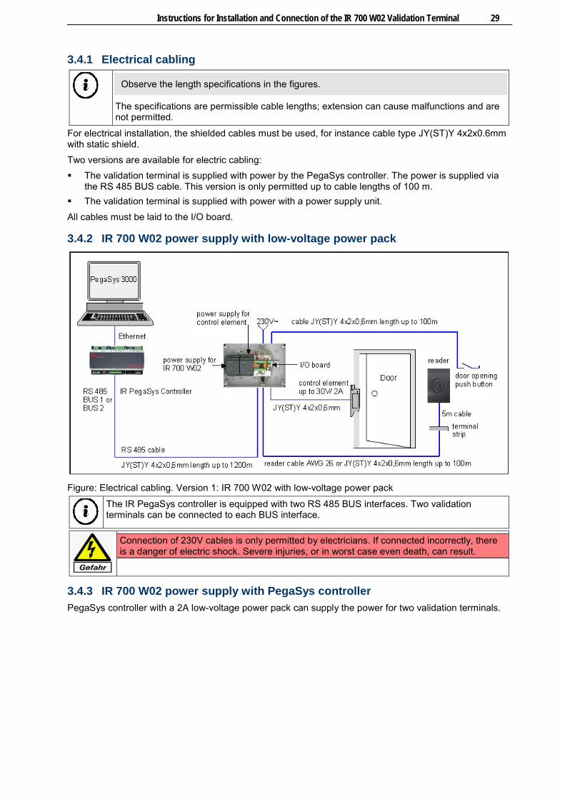
3.4.1 Electrical cabling
Observe the length specifications in the figures.
The specifications are permissible cable lengths; extension can cause malfunctions and are not permitted.
For electrical installation, the shielded cables must be used, for instance cable type JY(ST)Y 4x2x0.6mm with static shield. Two versions are available for electric cabling: The validation terminal is supplied with power by the PegaSys controller. The power is supplied via
the RS 485 BUS cable. This version is only permitted up to cable lengths of 100 m. The validation terminal is supplied with power with a power supply unit. All cables must be laid to the I/O board.
3.4.2 IR 700 W02 power supply with low-voltage power pack
Figure: Electrical cabling. Version 1: IR 700 W02 with low-voltage power pack
The IR PegaSys controller is equipped with two RS 485 BUS interfaces. Two validation terminals can be connected to each BUS interface.
Connection of 230V cables is only permitted by electricians. If connected incorrectly, there is a danger of electric shock. Severe injuries, or in worst case even death, can result.
3.4.3 IR 700 W02 power supply with PegaSys controller PegaSys controller with a 2A low-voltage power pack can supply the power for two validation terminals.

30 Instructions for Installation and Connection of the IR 700 W02 Validation Terminal
Please note: The voltage is supplied to the IR 700 W02 via the BUS cable and is only permitted up to BUS cable lengths of 100 m. For cable lengths over 100 m, power supply in the BUS cable is no longer possible for technical reasons. For cable lengths over 100 m, the IR 700 W02 requires a separate power supply unit with 18 to 24 VAC/VDC, 1 A.
Figure: Electrical cabling. Version 2: IR 700 W02 with power supply via RS 485 BUS cable
3.4.4 Installation: overview Overview of the parts to be installed:
Figure: Fastening (dimensions in mm)
1 Housing cover 3 Mounting plate
1a Snap-in elements 3a Drilling for reader cable
2 Reader housing with RFID board 4 I/O board

Instructions for Installation and Connection of the IR 700 W02 Validation Terminal 31
2a 5 m reader cable for connection to I/O board The reader cable can be extended to 100 m.
Fastening the reader housing The reader housing is designed for installation in indoor and outdoor environments (IP 65). Installation is performed on flat walls or columns, e.g. next to or on door frames (recommended installation height, approx. 1.1 m). A mounting plate is used for mounting. The plate is screwed in with two counter-sunk bolts (TOP).
The mounting plate enclosed in delivery may also be used as boring pattern. To draw the bore holes, hold the plate against the wall as shown in the figure. Take into consideration that the mounting plate is not symmetrical due to the cable bore (2a). In the figure, the installation position is marked by TOP.
The mounting plate must be flat against the base and must not get twisted out of shape when screwed down. The housing cover will not lock in securely to a twisted mounting plate and the cover may come off later.
The countersunk screws must end up flush with the countersunk holes and not protrude. The minimum distance to other devices equipped with RFID technology is 30 cm. When the device is fastened to a metal surface, the reading distance is reduced.
Installing the I/O board The board enables access control. Electric door openers up to 30V 2A can be switched with an NO and NC contact. Installation is performed separated from the validation terminal in the secured area, e. g. in the 3050121300 installation or a suitable appliance case.
3.4.5 Address setting The IR PegaSys controller manages validation terminals using addresses. Set the address 1 (A) or 2 (B) with the address switch.
Addresses may not be assigned twice. It is common practice, to assign address 1 to the first validation terminal.
See also IR 700 W02: Components ...................................................................................................... 27
3.4.6 Connect the electrical cables: IR 700 W02 connection overview
For compliance with the required EMC values, cable shields (sh) must be connected as shown in the figure. EMC = Electromagnetic compatibility according to EN 60950, EN 300330, EN 381-489, CE 0682

32 Instructions for Installation and Connection of the IR 700 W02 Validation Terminal
Connection overview for power supply with low-voltage power pack
Connection overview for power supply with PegaSys controller
The PegaSys controller can take over the power supply only on BUS lengths of less than 100 meters. For lengths of over 100 meters and for PoE, the validation terminal needs its own power supply. For compliance with the required EMC values, protective earth conductors and cable shields must be connected as shown in the figure.
Connecting the power supply Power supply is possible: With a 18 to 24 VAC/VDC low-voltage power pack. Over the PegaSys controller (terminals V+/V-) and the RS 485 BUS cable for lengths up to 100 m.
The IR 700 W02 requires functional earthing at terminal screw 4.
Connecting the BUS cable The validation terminal is connected to the PegaSys controller on BUS 1 or BUS 2.

Instructions for Installation and Connection of the IR 700 W02 Validation Terminal 33
Connecting the electric door opener The I/O board switches electric door openers up to 30V 2A with an NO or NC contact. Default factory setting: NO contact. Connect electric door openers and the required power supply as shown.
The electric door opener requires its own power supply; the power supply of the validation terminal may not be used.
Setting the NO/NC switching contact Electric door openers can be switched with an NO or NC contact. To use the NC contact as a switching contact, the position of the plugin bridge Br.1 needs to be moved.
Connecting the reader cable The reader is connected as shown in the figure.
Connecting the door opener button Basic requirement: PegaSys controller with software versions ≥ 3.01. A door opener push-button with NO contact can be connected to the I/O board. After actuation of the push-button, the relay switches the electric door opener. The time corresponds to the door relay time that has been set in the PegaSys software. Connection is made as shown in the connection overview, shown at input IN 2.
See also Connect the electrical cables: IR 700 W02 connection overview ........................................... 31
3.4.7 Initial operation Initial operation must be carried out together with the PegaSys controller.
See also Initial Operation ......................................................................................................................... 9
3.4.8 Closing the reader housing The reader housing is covered with the housing cover after the function check. To close the housing, the cover is positioned over the housing and pressed down until the snap-in elements (1a) lock into place in the mounting plate.
The reader cover is destroyed when disassembled.
See also Spare Parts ............................................................................................................................. 35
3.5 IR 700 W02: Operation For reading and writing, hold the identification medium as close as possible to and slightly above the centre of the reader (see figure below). After a green or red light, the identification medium can be removed.

34 Instructions for Installation and Connection of the IR 700 W02 Validation Terminal
RFID pictogram acknowledges in colour. Blue= IR 700 W02 is ready for operation.
Figure: Recommended positioning of the RFID identification media.
3.5.1 Writing with IR 700 W02 When the pictogram is backlit illuminated blue, the IR 700 W02 is ready for operation and can write NetworkOnCard access permissions on the RFID identification media. Procedure: Hold your RFID identification medium parallel and as close as possible to reader. The closer the
spacing, the better the read-write operation functions. Hold the RFID identification medium until the RFID pictogram lights up green or red and the reader
acknowledges with an audible "beep". Remove the RFID identification medium.
3.5.2 IR 700 W02: Audible acknowledgements The built-in buzzer acknowledges read and write operations as follows: Short beep Positive acknowledgement. Data properly written, read. Intermittent beep Negative acknowledgement. Data cannot be written or read. We
recommend repeating the procedure and notifying the administrator.
3.5.3 IR 700 W02: Visual acknowledgement The backlit illuminated pictogram signals as follows: Blue display Operating voltage switched on. IR 700 W02 is ready for operation. Red flashing display Access permissions are written. Green display Positive acknowledgement. Data was read and written. Red display Negative acknowledgement. Data cannot be written or read. We
recommend repeating the process. If the display is red again, please contact the administrator.
3.5.4 Door opening The door opening occurs after: The RFID identification media is read. The door opener push-button has been pressed. After a positive acknowledgement, the electric door opener is activated and the door can be opened.
The door opening time can be changed in the PegaSys 3000 software.

Instructions for Installation and Connection of the IR 700 W02 Validation Terminal 35
3.6 Maintenance The device is maintenance-free.
Perform maintenance on the electric door opener according to the manufacturer's specifications.
3.7 Janitorial For cleaning the housing, use a plastic cleaner or methylated spirit,
Do not use any cleaning agents that contain benzine or solvents.
3.8 Spare Parts A housing cover is available as a spare part. Order Number: 3050121000
3.9 Technical Data Power supply Low-voltage with 18 VAC to 24 VAC or via the PegaSys
controller and the RS 485 BUS cable.
Power consumption max. 3 VA, 130 mA
Fuse protection Self-resetting fuse on the I/O board (NTC resistor)
RFID credential reader Mifare or LEGIC depending on order
Read range Up to 40 mm, depending on the size of the identification medium used
Interface to the IR PegaSys controller RS 485 (2-wire)
Relay / switching power 1 relay up to 30V/2A with NO and NC contact
Inputs 1 Input for push-button with NO contact
User information Buzzer, LEDs: Blue, red, green
Protection category Reader IP 65 (encapsulated electronics) I/O board IP 00
General Data
Housing material (reader) Plastic PC Makrolon
Operating temperature From -25 C° to +55 °C
Humidity Max. 95%, non-condensing
Electromagnetic compatibility EN 60950, EN 300330, EN 381-489, CE 0682
Dimensions (HxWxD in mm) Wall reader: 119 x 77 x 23 I/O board: 52 x 30 x 16
Weight Approx. 0.4 kg
Installation type Wall reader: Wall-mounting with concealed cable feed I/O board: Installation, e.g. into DIN appliance cases
Colour Anthracite or light grey


Installation Instructions for W02 Wall Reader


Instructions for Installation and Connection of the PegaSys W02 Wall Reader 39
4 Instructions for Installation and Connection of the PegaSys W02 Wall Reader
4.1 Introduction
4.1.1 Scope of delivery The following is included in delivery: Housing cover. Reader housing with encapsulated RFID board and 5 m reader cable. Mounting plate. I/O board for control of an electric door opener, up to 30 V, 2A. Material for wall mounting of the reader housing. Upon receiving them, check that the goods are complete.
4.1.2 Validity of the documentation The documentation is valid for the PegaSys W02 wall reader. It contains information on installation, connection and initial operation. For translation reasons, the figure texts are in English.
See also Connect the electrical cables: Connection overview .............................................................. 43
4.1.3 Intended use PegaSys W02 wall readers are used for reading data from RFID identification media and for control of electric actuators. Any other use is not in accordance with the intended purpose and is therefore not permitted.
4.1.4 Storage The device has to be stored in a dry place.
4.1.5 Disposal
After proper operation, the device is to be disposed of properly as electronic scrap. The owner can dispose of the device himself or return it to the supplier.
4.2 W02 Wall Reader: Function The W02 PegaSys wall reader, hereinafter wall reader, controls access in the security zone. After reading RFID identification media (RFID = Radio Frequency Identification) with NetworkOnCard access permissions, a relay switches to control an electric door opener up to 30V/2A. The wall reader stores all RFID identifications with time and date for subsequent analysis, e.g. access tracking. For initial operation, you will need the following cards of the programming card set:
1. Facility card with object code (customer-specific object number). The card data are unique, customer-specific and have been written to the card by the supplier.
2. Door initialisation card. Use the PegaSys 3000 software to configure all door data for this wall reader, such as door number, door group, door function, door opening times, time models, time and date. Then write the data to the door initialisation card.
You must have both cards available during initial operation.

40 Instructions for Installation and Connection of the PegaSys W02 Wall Reader
4.3 W02 Wall Reader: Components The wall reader consists of the following components:
IR 700 W02 housing with pictogram (arrow)
Reader housing with RFID board and 5 m reader cable
Mounting plate
The default setting of the RFID board provides a maximum read range performance. Modification is not permitted. The read range depends on the size of the identification medium. For cheque card format it can be up to 40 mm.
I/O board with relay and screw terminals
Address switch (without function)
Jumper Br. 1 for setting the NO or NC switching contact
4.4 W02 Wall Reader: Installation and Initial Operation This chapter contains information on installation and initial operation. After performing the eight steps, the wall reader takes over access control. We recommend proceeding as follows:
1. Install the electric cables required for operation.
2. Install the power supply.
3. Installation: Mount the reader housing, I/O board and electric door opener.
4. Connect the electrical cables.
5. Perform a cold start to erase saved data.
6. Read facility card and door initialisation card.
7. Perform function check with access authorised RFID identification media.
8. Lock reader housing with housing cover.

Instructions for Installation and Connection of the PegaSys W02 Wall Reader 41
4.4.1 Installing the cables The figure shows the electrical cabling. All cables must be laid to the I/O board.
Only install shielded cable, such as the cable type JY(ST)Y 4x2x0.6mm. Maintain a minimum distance of 10 cm to parallel heavy-current cables. The 5 m long reader cable can be extended to 100 m. Maintain a distance of 30 cm to other devices that use RFID technology.
Figure: Electrical wiring
4.4.2 Installing the power supply unit
Connection of 230V cables is only permitted by electricians. If connected incorrectly, there is a danger of electric shock. Severe injuries, or in worst case even death, can result.
Power supply for the wall reader A transformer with 18 VAC to 24 VAC or a DC power unit with 18 VDC to 30 VDC can be used for power supply.
Power supply for the electric door opener The wall reader switches the electric door opener with a power of 30V/2A. We recommend an own power supply for the door opener, suited to the corresponding power needs. The wall reader power pack may only be used for power supply if no voltage noise occurs when the electric door opener is switched.

42 Instructions for Installation and Connection of the PegaSys W02 Wall Reader
4.4.3 Installation: overview Overview of the parts to be installed:
Figure: Fastening (dimensions in mm)
1 Housing cover 3 Mounting plate
1a Snap-in elements 3a Drilling for reader cable
2 Reader housing with RFID board 4 I/O board
2a 5 m reader cable for connection to I/O board The reader cable can be extended to 100 m.
Fastening the reader housing The reader housing is designed for installation in indoor and outdoor environments (IP 5). Installation is performed on flat walls or columns, e.g. next to or on door frames (recommended installation height, approx. 1.1 m). A mounting plate is used for mounting. The plate is screwed in with two counter-sunk bolts (TOP).
The mounting plate enclosed in delivery may also be used as boring pattern. To draw the bore holes, hold the plate against the wall as shown in the figure. Take into consideration that the mounting plate is not symmetrical due to the cable bore (2a). In the figure, the installation position is marked by TOP.
The mounting plate must be flat against the base and must not get twisted out of shape when screwed down. The housing cover will not lock in securely to a twisted mounting plate and the cover may come off later.
The countersunk screws must end up flush with the countersunk holes and not protrude. The minimum distance to other devices equipped with RFID technology is 30 cm. When the device is fastened to a metal surface, the reading distance is reduced.
Installing the I/O board The board enables access control. Electric door openers up to 30V 2A can be switched with an NO and NC contact. Installation is performed separated from the validation terminal in the secured area, e. g. in the 3050121300 installation or a suitable appliance case.
Installing the electric door opener Install the electric door opener according to the manufacturer's specifications.

Instructions for Installation and Connection of the PegaSys W02 Wall Reader 43
4.4.4 Connect the electrical cables: Connection overview The following is connected to I/O board: Reader electronics on terminal KL.2. Power supply on terminal KL.1. Electric door opener with power supply on terminal KL.1.
Connection overview
Figure: Connections on the I/O Board
Connecting the reader cable Connect the reader cable as shown in the figure (A).
The black isolated cable shield must be connected to achieve the required EMC values. EMC = Electromagnetic compatibility according to EN 60950, EN 300330, EN 381-489, CE 0682
Connecting the power supply Connect the power units to the power supply of the wall reader as shown in the figure (B).
The wall reader requires functional earthing at terminal screw 4 to comply with the required EMC values.
Connecting the electric door opener Connect the electric door opener to the power supply as shown in the figure (C).
Earth the cable shield of the cable to the power supply of the electric door opener.
Setting the NC switching contact The electric door opener can be switched with an NO or NC contact. To use the switching contact as NC, the jumper Br. 1 must be in the NC position.
Note: An electric door opener does not replace locking the door with a bolt. It is primarily intended for regular business hours, whereas the door is locked with a bolt at night.
4.4.5 Performing a cold start to erase saved data
The wall reader reads a facility card with new object code only after a "cold boot".

44 Instructions for Installation and Connection of the PegaSys W02 Wall Reader
The following procedure triggers a cold boot and deletes saved data:
1. Bridge the PIN 4 and 6 of the jumper socket J 1 with a wire (short-circuit).
2. Switch on the operating voltage.
3. Wait for the start of the cold boot. The red and green LEDs acknowledge the start by flashing quickly. Please note: Through the sealing compound the LEDs light up orange.
4. Remove the short circuit bridge after the first flash.
5. Wait for the end of the cold boot. The procedure can take several seconds. The blue LEDs light up in standby.
Check the electric connection if no LEDs light up.
Figure: Reader housing with jumper socket for cold boot.
4.4.6 Reading in the facility card and door initialisation card The wall reader needs the data of the facility card and the door initialisation card. To save the data, first the facility card and then the door initialisation card must be held in front of the wall reader. Hold each card in front of the wall reader until saving is confirmed by flashing green twice.
4.4.7 Function check with RFID identification media. To check the functions, you need RFID identification media with NetworkOnCard access permissions. Hold the RFID identification media in front of the wall reader. The wall reader must acknowledge reading with a short "beep", a green display and switching the electric door opener. A red LED display with intermittent "beep" indicates: The RFID identification media do not have NetworkOnCard access permissions for the wall reader.
Check the access permissions with the PegaSys 3000 software. Configure and write new NetworkOnCard access permissions to the identification media.
Read error. Hold the identification media up to the wall reader again.
4.4.8 Closing the reader housing The reader housing is covered with the housing cover after the function check. To close the housing, the cover is positioned over the housing and pressed down until the snap-in elements (1a) lock into place in the mounting plate.
The reader cover is destroyed when disassembled.
See also Spare Parts ............................................................................................................................. 35

Instructions for Installation and Connection of the PegaSys W02 Wall Reader 45
4.5 Door Opening with RFID Identification Media
A blue display indicates: The wall reader is ready for operation. In order for a door to be opened, the wall reader must read the data of the identification
medium and evaluate the data. For reading, hold the identification medium as close as possible to and slightly above the centre of the reader. After a green or red light, the identification medium can be removed.
RFID pictogram acknowledges in colour. Blue= IR 700 W02 is ready for operation.
Figure: Recommended positioning of the RFID identification media.
4.5.1 Acknowledgements The wall reader acknowledges reading of the identification medium as follows: Short "beep" and green light The door can be opened. Intermittent beep and red light Door cannot be opened. The identification medium is not
authorised to enter the security zone or a read error has occurred.
4.6 Maintenance The device is maintenance-free.
Perform maintenance on the electric door opener according to the manufacturer's specifications.
4.7 Janitorial For cleaning the housing, use a plastic cleaner or methylated spirit,
Do not use any cleaning agents that contain benzine or solvents.
4.8 Spare Parts A housing cover is available as a spare part. Order Number: 3050121000

46 Instructions for Installation and Connection of the PegaSys W02 Wall Reader
4.9 Technical Data Power supply:
Low-voltage 18 VAC to 24 VAC, or 18 VDC to 30 VDC
Power consumption max. 3 VA, 130 mA
Fuse protection Self-resetting fuse 1 on the I/O board
RFID reading process Mifare or LEGIC depending on order
Read range of the RFID reader Up to 40 mm, depending on the size of the identification medium used
Relay / switching power 1 relay with NO/NC contacts/ up to 30V/2A
User information Buzzer, LEDs: Blue, red, green
General data:
Protection category Reader IP 65 (encapsulated electronics) I/O board IP 00
Operating temperature From -25 C° to +55 °C
Humidity Max. 95%, non-condensing
Electromagnetic compatibility EN 60950, EN 300330, EN 381-489, CE 0682
Dimensions (HxWxD) Wall reader: 119x77x23 mm I/O board: 52x30x16 mm
Weight Approx. 0.4 kg
Installation type Wall reader: For surface-mounting I/O board: Installation into DIN appliance cases possible
Colour Anthracite or light grey

47
5 Index A
acknowledgement • 22, 34, 45 adapter board • 16
C
cable connection • 8 cabling • 5, 29, 41
D
disposal • 1 door initialization card • 44 door opener • 7, 21, 33, 42, 43
F
facility card • 44
H
housing, open/close • 16
I
I/O board • 16, 21, 31 initial operation • 9, 21, 40 installation • 28 interface • 5 IR 712 • 15
J
janitorial • 23
L
LED +5V • 4
M
maintenance • 22
N
network • 10
O
online mode • 9 operating voltage • 5, 9
P
password • 10 PegaSys controllers • 1 PoE (Power over Ethernet) • 6 Power over Ethernet • 6 power supply • 5, 6, 18, 29, 32
R
Reset • 4
S
service interface • 5 software • 1 software version • 11 spare parts • 35 storage • 1 switching contact • 43
T
TELNET • 9, 11
U
update • 5
V
validation terminal • 2
W
wall reader W02 • 39

Ingersoll Rand Security TechnologiesBescott Crescent, WalsallWest Midlands WS1 4DL. UKTel.: +44 (0) 1922 707400Fax: +44 (0) 1922 707481www.pegasys.ingersollrand.com
Ingersoll Rand’s Security Technologies Sector is a leading global provider of products and services that make environments safe, secureand productive.The sector’smarket-leading products include electronic and biometric access-control systems; time-and-attendanceand personnel scheduling systems; mechanical locks; portable security; door closers, exit devices, architectural hardware, and steel doors and frames; and other technologies and services for global security markets.
www.ingersollrand.com
Order-No. 3050132800 /01/01-2011


![Copyright c 2007 Pegasys Inc,All rights reserved. · Linear PCM Dolby Digital [Mono/Stereo] PEGASYS Dolby Digital Encoder SDK Encoder DATA DATA DATA Dolby](https://img.pdfslide.us/doc/110x75/5d676a0d88c993d5408b7516/copyright-c-2007-pegasys-incall-rights-linear-pcm-dolby-digital-monostereo.jpg)