Embed Size (px)
Citation preview
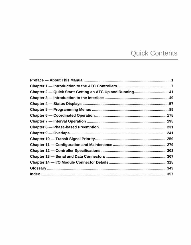
Quick Contents
Preface — About This Manual................................................................................... 1 Chapter 1 — Introduction to the ATC Controllers................................................... 7 Chapter 2 — Quick Start: Getting an ATC Up and Running................................. 41 Chapter 3 — Introduction to the Interface ............................................................. 49 Chapter 4 — Status Displays .................................................................................. 57 Chapter 5 — Programming Menus ......................................................................... 89 Chapter 6 — Coordinated Operation .................................................................... 175 Chapter 7 — Interval Operation ............................................................................ 195 Chapter 8 — Phase-based Preemption ................................................................ 231 Chapter 9 — Overlaps............................................................................................ 241 Chapter 10 — Transit Signal Priority.................................................................... 259 Chapter 11 — Configuration and Maintenance ................................................... 279 Chapter 12 — Controller Specifications............................................................... 303 Chapter 13 — Serial and Data Connectors .......................................................... 307 Chapter 14 — I/O Module Connector Details ....................................................... 315 Glossary .................................................................................................................. 349 Index ........................................................................................................................ 357
Operating Manual
Peek ATC Controller ATC-1000, ATC-2000 & ATC-3000 Advanced Traffic Controllers
9/7/2011 p/n: 99-537, Rev 3

manual assembly: 81-1285 manual content: 99-537, Rev 3 manual cover art: 99-538
Copyright © 2011 Peek Traffic Corporation. All rights reserved. Information furnished by Peek is believed to be accurate and reliable, however Peek does not warranty the accuracy, completeness, or fitness for use of any of the information furnished. No license is granted by implication or otherwise under any intellectual property. Peek Traffic reserves the right to alter any of the Company's products or published technical data relating thereto at any time without notice. No part of this publication may be reproduced, stored in a retrieval system, or transmitted in any form or via any electronic or mechanical means for any purpose other than the purchaser’s personal use without the expressed, written permission of Peek Traffic Corporation. Peek Traffic Corporation 2906 Corporate Way Palmetto, FL 34221 U.S.A. Trademarks Peek ATC Controller, ATC-1000, ATC-2000, ATC-3000, IQ-Link, ATCLink, GREENWave, and IQ Central are trademarks or registered trademarks of Peek Traffic Corporation in the United States and other countries. TransCore and TransSuite are registered trademarks of Roper Industries, Inc. Microsoft and Windows are trademarks or registered trademarks of Microsoft Corporation. Other brands and their products are trademarks or registered trademarks of their respective holders and should be noted as such.

Quick Contents
Preface — About This Manual................................................................................... 1 Chapter 1 — Introduction to the ATC Controllers................................................... 7 Chapter 2 — Quick Start: Getting an ATC Up and Running................................. 41 Chapter 3 — Introduction to the Interface ............................................................. 49 Chapter 4 — Status Displays .................................................................................. 57 Chapter 5 — Programming Menus ......................................................................... 89 Chapter 6 — Coordinated Operation .................................................................... 175 Chapter 7 — Interval Operation ............................................................................ 195 Chapter 8 — Phase-based Preemption ................................................................ 231 Chapter 9 — Overlaps............................................................................................ 241 Chapter 10 — Transit Signal Priority.................................................................... 259 Chapter 11 — Configuration and Maintenance ................................................... 279 Chapter 12 — Controller Specifications............................................................... 303 Chapter 13 — Serial and Data Connectors .......................................................... 307 Chapter 14 — I/O Module Connector Details ....................................................... 315 Glossary .................................................................................................................. 349 Index ........................................................................................................................ 357

ATC-1000, ATC-2000 & ATC-3000 Advanced Traffic Controllers iii
Contents
Preface — About This Manual................................................................................... 1
Purpose and Scope................................................................................................................................. 1 Assumptions............................................................................................................................................ 1 Related Documents................................................................................................................................. 3 Technical Assistance............................................................................................................................... 4 Conventions Used in this Manual............................................................................................................ 4
Typographic Conventions ................................................................................................................. 4 Keyboard and Menu Conventions .................................................................................................... 5 Symbol Conventions......................................................................................................................... 5
Chapter 1 — Introduction to the ATC Controllers................................................... 7 ATC-1000 Controller......................................................................................................................... 8 ATC-2000 Controller....................................................................................................................... 10 ATC-3000 Controller....................................................................................................................... 10 Traffic Engine.................................................................................................................................. 11
Controller Hardware .............................................................................................................................. 13 Enclosure........................................................................................................................................ 13 Operating System, Firmware and Memory ..................................................................................... 14 Display ............................................................................................................................................ 14 Keypad............................................................................................................................................ 15 Comms and Utility Connectors ....................................................................................................... 17 I/O Module Connectors................................................................................................................... 21 Heartbeat LED ................................................................................................................................ 22 Data Key Port ................................................................................................................................. 22 Power System................................................................................................................................. 22
Basic Operations ................................................................................................................................... 24 Setting the Date and Time .............................................................................................................. 24 Setting Up Daylight Savings Time .................................................................................................. 27 Adjusting Screen Contrast .............................................................................................................. 30 Turning the Backlight On and Off ................................................................................................... 31 Entering Edit Mode ......................................................................................................................... 32 Entering the Menu System ............................................................................................................. 32 Entering the Utilities Menus ............................................................................................................ 33 Viewing Help Screens..................................................................................................................... 33
Contents
iv ATC-1000, ATC-2000 & ATC-3000 Advanced Traffic Controllers
GreenWave Firmware............................................................................................................................ 34 Checking the Current Version of Firmware ..................................................................................... 34 Updating Firmware Using a USB Drive........................................................................................... 35
Using the ATCLink Utility with an ATC Controller.................................................................................. 38 Using an ATC Controller With IQ Central .............................................................................................. 39
Chapter 2 — Quick Start: Getting an ATC Up and Running ................................ 41 Overview................................................................................................................................................ 42 Hardware Setup Checklist ..................................................................................................................... 42 Software Setup Checklist....................................................................................................................... 43
Setting the Local Ethernet Settings................................................................................................. 43 Configuring ATCLink and the SNMP Manager ............................................................................... 45 Loading a Default Database Into the Controller .............................................................................. 45
Field Deployment................................................................................................................................... 46 Programming a Basic Intersection......................................................................................................... 47
Chapter 3 — Introduction to the Interface ............................................................. 49 Overview................................................................................................................................................ 50 Navigating in the Environment............................................................................................................... 51 Entering the Menu System .................................................................................................................... 52 Firmware Flow Chart ............................................................................................................................. 53 Main, Utilities, and USB Menu Systems ................................................................................................ 54
Chapter 4 — Status Displays .................................................................................. 57 Overview of the Status Screens ............................................................................................................ 58
Status Menu .................................................................................................................................... 58 Navigating the Status Screens........................................................................................................ 58
Controller Status Menu .......................................................................................................................... 59 Runtime Status Screen ................................................................................................................... 59 Coordination Status Screen ............................................................................................................ 64 Time of Day Status Screen ............................................................................................................. 68 Preemption Status Screen .............................................................................................................. 69 Detectors Status Screens ............................................................................................................... 71 TSP Status Screens........................................................................................................................ 72 Overlaps Status Screens ................................................................................................................ 76 Sequencing Status Screen.............................................................................................................. 78 Texas Diamond Status screen ........................................................................................................ 79
Inputs/Outputs Status Menu .................................................................................................................. 80 Inputs Status Screen....................................................................................................................... 80 Outputs Status Screen .................................................................................................................... 82 SDLC & FIO Status Screens........................................................................................................... 83
Alarms Status Menu .............................................................................................................................. 84 Unit Alarm Status 1 & 2 Screen ...................................................................................................... 84 Short Alarm Status Screen.............................................................................................................. 85
MMU Status Screens............................................................................................................................. 86 Revisions Screen................................................................................................................................... 87
Chapter 5 — Programming Menus ......................................................................... 89 Overview of the Programming Screens ................................................................................................. 90 Unit Configuration Menu ........................................................................................................................ 90
Start-Up Configuration Screen ........................................................................................................ 91 Program (MUTCD) Flash Screen.................................................................................................... 93 Phase Compatibility Screens .......................................................................................................... 95 Channels Screens........................................................................................................................... 96 Comm Ports & IP/Cab Setup Menu ................................................................................................ 97 Ring Sequencing Screens............................................................................................................. 114 USTC Miscellaneous Screen ........................................................................................................ 116 ABS ZERO Screen........................................................................................................................ 118
Contents
ATC-1000, ATC-2000 & ATC-3000 Advanced Traffic Controllers v
Controller Menu................................................................................................................................... 119 Phase Enables Screen ................................................................................................................. 120 Green Timing Screens.................................................................................................................. 121 Clearance Timing Screens ........................................................................................................... 123 Pedestrian Timing Screens........................................................................................................... 124 Added Initial Timing Screens ........................................................................................................ 125 Gap Reduction Timing Screens.................................................................................................... 126 Dynamic Max Timing Screens ...................................................................................................... 129 Phase Options Screens ................................................................................................................ 130 Recalls .......................................................................................................................................... 133 Overlap Menu ............................................................................................................................... 135
Coordination Menu.............................................................................................................................. 136 Coordination Variables Screen ..................................................................................................... 136 Pattern Table Screens .................................................................................................................. 139 Split Table Screens....................................................................................................................... 139 Offset Correction Ext/Reduce ....................................................................................................... 141 Offset Correction Percent ............................................................................................................. 142
Time of Day Menu............................................................................................................................... 143 Time of Day Actions Menu............................................................................................................ 143 Day Plan Screens ......................................................................................................................... 146 Schedule Screens......................................................................................................................... 147 Override Commands Screen ........................................................................................................ 147 Set Local Time Screen ................................................................................................................. 149 Advanced Time Setup Screen ...................................................................................................... 149 Daylight Saving Settings Menu..................................................................................................... 150
Detectors Menu................................................................................................................................... 157 Vehicle Detector Options Screens................................................................................................ 157 Vehicle Detector Timing Screens ................................................................................................. 159 Detector Call Phases Screen........................................................................................................ 160 Switch Phases Screen.................................................................................................................. 161 Pedestrian Detectors Screen........................................................................................................ 161 Enhanced Detectors Screen......................................................................................................... 163
Preemption Menu................................................................................................................................ 164 Using the Interval Menu ...................................................................................................................... 165 Transit Signal Priority Menu ................................................................................................................ 166 System Maintenance Menu................................................................................................................. 167
Database Utilities Screen ............................................................................................................. 167 Copy Database Functions ............................................................................................................ 170 Diagnostics Mode ......................................................................................................................... 173
Logs Menu........................................................................................................................................... 174 Chapter 6 — Coordinated Operation .................................................................... 175
General Overview of Coordination ...................................................................................................... 176 Signal Timing in a Coordinated Environment...................................................................................... 177
Cycle Length................................................................................................................................. 177 Local Cycle ................................................................................................................................... 177 Split (Phase Allocation)................................................................................................................. 177 Local Cycle Reference Point ........................................................................................................ 177 Master Cycle................................................................................................................................. 178 Offset ............................................................................................................................................ 178
Synchronization Methods.................................................................................................................... 179 Historical Sources of Sync Pulses ................................................................................................ 179 Offset Seeking .............................................................................................................................. 179
Coordination of an Phase-Based Controller........................................................................................ 180 Functions Used to Coordinate an Actuated Controller ................................................................. 180 Example of Force Off And Permissive Placement........................................................................ 180
Contents
vi ATC-1000, ATC-2000 & ATC-3000 Advanced Traffic Controllers
Programming a Peek ATC Controller for Coordination ....................................................................... 183 Coordination Parameters Explanation .......................................................................................... 183 Parameter Value Organization...................................................................................................... 184 Parameter Entry into the ATC Series Controller ........................................................................... 185 Time of Day (TOD) Programming to Run Coordination ................................................................ 187 Auto Permissive and Force Off Calculations................................................................................. 189 Notes About Programming a Coordinated Pattern Table.............................................................. 191 Verifying Proper Coordinated Operation ....................................................................................... 194
Chapter 7 — Interval Operation ............................................................................ 195 Overview.............................................................................................................................................. 196
Calling the Plans ........................................................................................................................... 197 Using the Interval Programming Screens............................................................................................ 199
Timing Plans Screens ................................................................................................................... 199 Signal Plans Menu ........................................................................................................................ 202 Interval-based Preemption ............................................................................................................ 207
Interval-Based Preemption Programming Screens ............................................................................. 210 Modifiers Screens ......................................................................................................................... 210 Track Interval Data Menu and Screens......................................................................................... 211 Dwell Interval Data Menu and Screens......................................................................................... 214 Exit Interval Data Menu and Screens............................................................................................217 Interval Skipping Screens ............................................................................................................. 219
Interval Preemption Priority ................................................................................................................. 222 Input Priority .................................................................................................................................. 222
Setting up an Actuated Leading or Lagging Left Turn ......................................................................... 224 Wrong Way to Program a Leading Left Turn ................................................................................ 224 Correct Way to Program a Leading Left Turn ............................................................................... 226 Correct Way to Program a Lagging Left Turn ............................................................................... 228
Chapter 8 — Phase-based Preemption................................................................ 231 Overview.............................................................................................................................................. 232 Programming Phase-Based Preemption .............................................................................................235
Preemption Menu.......................................................................................................................... 235 Control and Timing Screens.......................................................................................................... 235 Phase Pedestrian Overlaps Screens ............................................................................................ 239
Chapter 9 — Overlaps............................................................................................ 241 Overview.............................................................................................................................................. 242
Overlaps Menu.............................................................................................................................. 243 Overlap Types and Modifiers ........................................................................................................ 244 Overlaps and Compatibility ........................................................................................................... 248
Vehicle Overlaps.................................................................................................................................. 249 Leading or Delayed Vehicular Overlaps........................................................................................ 251 Steps to Create an Overlap........................................................................................................... 253
Pedestrian Overlaps ............................................................................................................................ 254 Pedestrian Overlap Types............................................................................................................. 255 Steps to Create a Ped Overlap ..................................................................................................... 257
Chapter 10 — Transit Signal Priority ................................................................... 259 What is TSP?....................................................................................................................................... 260 How TSP Functions ............................................................................................................................. 261
Prioritization Methods.................................................................................................................... 263 Getting TSP Set Up ............................................................................................................................. 264 TSP Screens and Parameters ............................................................................................................. 266
Unit Parameters ............................................................................................................................ 267 Run Parameters ............................................................................................................................ 268 TSP Action Plans .......................................................................................................................... 270 Run Configuration ......................................................................................................................... 271
Contents
ATC-1000, ATC-2000 & ATC-3000 Advanced Traffic Controllers vii
Queue Jumping ............................................................................................................................ 275 Split Table..................................................................................................................................... 276
TSP Status Monitoring ........................................................................................................................ 277 TSP Troubleshooting........................................................................................................................... 277
Chapter 11 — Configuration and Maintenance ................................................... 279 Overview ............................................................................................................................................. 280 Utilities Menus..................................................................................................................................... 280
Utilities Menu for the Keyboard and Display................................................................................. 280 Diagnostics Mode ......................................................................................................................... 281
USB Operations .................................................................................................................................. 288 USB Menu .................................................................................................................................... 288 Moving Databases Using a USB Drive ......................................................................................... 289 Moving Logs Using a USB Drive .................................................................................................. 290 USB File System........................................................................................................................... 291
Data Logging ....................................................................................................................................... 292 Controller Message Log................................................................................................................ 292 NTCIP Event Log.......................................................................................................................... 293 Advanced Controller Logging Menu ............................................................................................. 293 Setup Logging Options ................................................................................................................. 293 View Logs Screen......................................................................................................................... 295
System Maintenance........................................................................................................................... 297 Preventive Maintenance and Calibration ...................................................................................... 297 Diagnosing Controller Operation .................................................................................................. 297
Troubleshooting................................................................................................................................... 297 Troubleshooting Transit Signal Priority Operation ........................................................................ 299
Chapter 12 — Controller Specifications............................................................... 303 Overview of Controller Specifications ................................................................................................. 304
Physical/Environmental Specifications ......................................................................................... 305 NTCIP Compliance ....................................................................................................................... 306
Chapter 13 — Serial and Data Connectors .......................................................... 307 Overview ............................................................................................................................................. 308 Port 1 - SDLC Connector .................................................................................................................... 308 Port 2 – RS-232C Connector .............................................................................................................. 309 Port 3 – Communications Module Port ............................................................................................... 310 Port 4 - Local Connector ..................................................................................................................... 311 Port 5 – Spare/UPS Connector ........................................................................................................... 312 Ethernet Connectors ........................................................................................................................... 313 USB Connectors.................................................................................................................................. 314
Chapter 14 — I/O Module Connector Details ....................................................... 315 Connector Details................................................................................................................................ 316 NEMA TS2 Type 1 I/O Module............................................................................................................ 316
Port A Connector .......................................................................................................................... 316 NEMA TS2 Type 2 I/O Module............................................................................................................ 318
Port A Connector .......................................................................................................................... 318 Port B Connector .......................................................................................................................... 323 Port C Connector .......................................................................................................................... 325
HMC-1000 I/O Module ........................................................................................................................ 328 HMC Input / Output Connector ..................................................................................................... 328 Stop Time Switch.......................................................................................................................... 330
LMD40 I/O Module .............................................................................................................................. 331 LMD40 Port A Connector.............................................................................................................. 331 LMD40 Port B Connector.............................................................................................................. 333 LMD40 Communication Inputs Connector.................................................................................... 334 LMD Port D Connector ................................................................................................................. 335
Contents
viii ATC-1000, ATC-2000 & ATC-3000 Advanced Traffic Controllers
Closed Loop D Module ........................................................................................................................ 338 Auxiliary Connector (37 Pin) ......................................................................................................... 338 Preemption Connector (25 Pin)..................................................................................................... 339 Coordination Connector (26 Pin)................................................................................................... 340
LMD9200 D Module............................................................................................................................. 341 Aux Connector .............................................................................................................................. 341 D Connector .................................................................................................................................. 341
Traconex D Module ............................................................................................................................. 343 Multisonics D Module........................................................................................................................... 345
Glossary.................................................................................................................. 349 Index ........................................................................................................................ 357
ATC-1000, ATC-2000 & ATC-3000 Advanced Traffic Controllers 1
Preface — About This Manual
PURPOSE AND SCOPE
This manual describes the installation and day-to-day operation of the ATC family of Advanced Traffic Controllers, including the ATC-1000, ATC-2000, ATC-3000, in both the shelf-mounted and rack-mounted versions. It discusses the options available for I/O and D modules for the controllers. It does not cover the modem and communications card options that are available for the controller modem slot, nor other external devices, as too many options exist. For such items, please refer to the documentation that is supplied along with the component.
The ATC controllers are designed to function well in conjunction with Peek’s software products, such as ATCLink and IQ Central, however aside from passing references, the use of these controllers with such software packages is not covered in this manual.
ASSUMPTIONS
It is assumed that the reader and user of this manual, the hardware, and the software tools described herein are authorized to work in and around traffic cabinets by the local traffic governing body. The reader should be familiar with the operation and wiring of traffic control cabinets in their area, and must be aware of, and follow, all safety and security protocols of the traffic agency. It is also assumed that the operator of the ATC traffic controllers is aware of what signal standards are being used within the cabinet in question (e.g. interval-based, NEMA TS 1, TS 2, NTCIP, etc.) and follows those standards.
Preface — About This Manual
2 ATC-1000, ATC-2000 & ATC-3000 Advanced Traffic Controllers
The Peek ATC controllers conform to the following standards:
National Electrical Manufacturer’s Association (NEMA) TS1 – NEMA is a North American trade organization that first defined the TS1 standard in 1978. This standard was formally declared obsolete in 1992, however it is still used in some locales.
NEMA TS2. This standard replaced the TS1 standard in the United States and Canada. The current published standard is TS2-2003. It specifies operational features and interchangeability requirements for manufacturers of traffic cabinet equipment.
Advanced Transportation Controller (ATC). The ATC standard, currently at Version 5.2b, published on September 25, 2006 was defined as a new standard integrating some features of TS2. ATC is primarily a North American standard. It was defined by a joint committee that included the U.S. Department of Transportation, AASHTO (the American Association of State Highway and Transportation Officials), the ITE (Institute of Transportation Engineers), and NEMA.
NTCIP (The National Transportation Communications for ITS Protocol). Compliant with the NTCIP 1201 and 1202 standards.
Wherever broadly-based standards do not exist to define the operation of the controller or the cabinet system, Peek designed a proprietary NTCIP system that uses the best practices and reliable, leading-edge technologies available for each application. This is particularly true of the Peek ATC Controller’s Preemption, Transit Signal Priority, and Interval-based traffic engines.
Controller Firmware This manual was written to describe the Peek ATC Controllers using GreenWave:
Version 3.7 If your controller is running firmware other than the version listed above, there may be some differences between the screens and functions described here and the screens and capabilities of your controller.
Related Documents
ATC-1000, ATC-2000 & ATC-3000 Advanced Traffic Controllers 3
RELATED DOCUMENTS
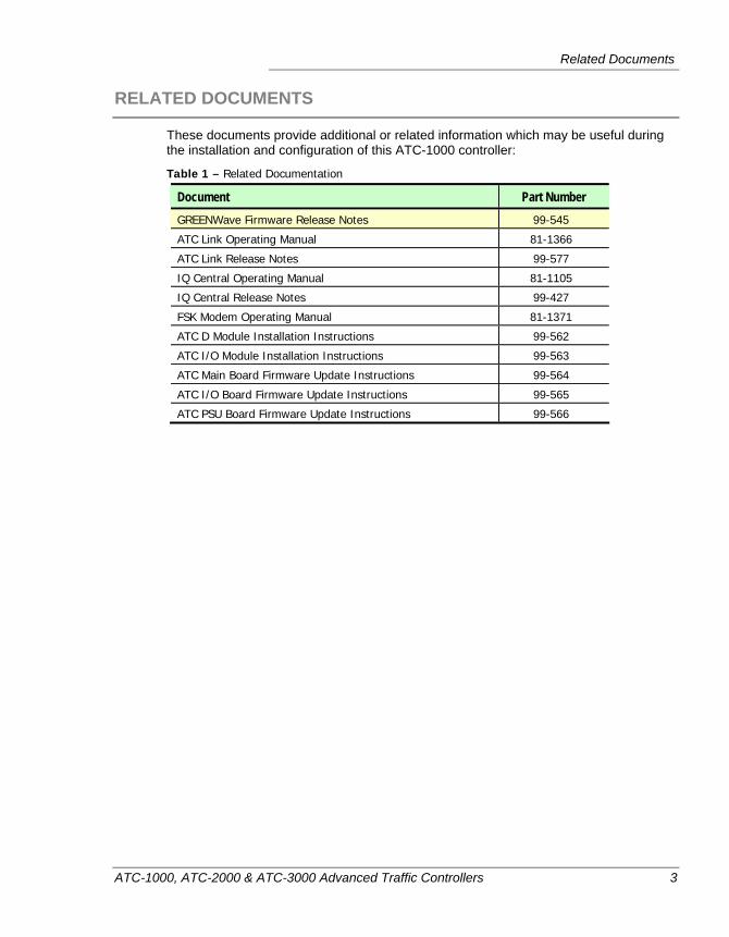
These documents provide additional or related information which may be useful during the installation and configuration of this ATC-1000 controller:
Table 1 – Related Documentation
Document Part Number GREENWave Firmware Release Notes 99-545
ATC Link Operating Manual 81-1366
ATC Link Release Notes 99-577
IQ Central Operating Manual 81-1105
IQ Central Release Notes 99-427
FSK Modem Operating Manual 81-1371
ATC D Module Installation Instructions 99-562
ATC I/O Module Installation Instructions 99-563
ATC Main Board Firmware Update Instructions 99-564
ATC I/O Board Firmware Update Instructions 99-565
ATC PSU Board Firmware Update Instructions 99-566
Preface — About This Manual
4 ATC-1000, ATC-2000 & ATC-3000 Advanced Traffic Controllers
TECHNICAL ASSISTANCE
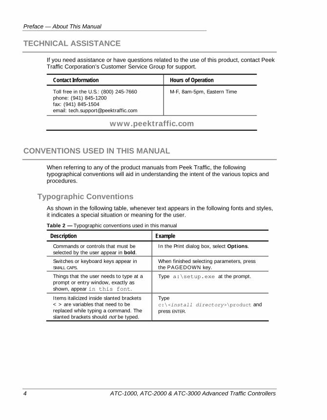
If you need assistance or have questions related to the use of this product, contact Peek Traffic Corporation’s Customer Service Group for support.
Contact Information Hours of Operation
Toll free in the U.S.: (800) 245-7660 phone: (941) 845-1200 fax: (941) 845-1504 email: [email protected]
M-F, 8am-5pm, Eastern Time
www.peektraffic.com
CONVENTIONS USED IN THIS MANUAL
When referring to any of the product manuals from Peek Traffic, the following typographical conventions will aid in understanding the intent of the various topics and procedures.
Typographic Conventions As shown in the following table, whenever text appears in the following fonts and styles, it indicates a special situation or meaning for the user.
Table 2 — Typographic conventions used in this manual
Description Example Commands or controls that must be selected by the user appear in bold.
In the Print dialog box, select Options.
Switches or keyboard keys appear in SMALL CAPS.
When finished selecting parameters, press the PAGEDOWN key.
Things that the user needs to type at a prompt or entry window, exactly as shown, appear in this font.
Type a:\setup.exe at the prompt.
Items italicized inside slanted brackets < > are variables that need to be replaced while typing a command. The slanted brackets should not be typed.
Type c:\<install directory>\product and press ENTER.
Conventions Used in this Manual
ATC-1000, ATC-2000 & ATC-3000 Advanced Traffic Controllers 5
Keyboard and Menu Conventions Some commands are accomplished with a pair or sequence of keystrokes or command entries. The way these should be done is indicated by the way they are shown in the instructions, as listed here.
Table 3 — Keyboard conventions used in this manual
Description Example A series of commands that need to be completed in sequence will be separated by a right slant bracket (>)
Go to Start > Programs > IQCentral and select IQCentral.
A dash, or hyphen, ( - ) indicates keys or controls that need to be pressed at the same time to activate the command
Press CTRL- p to print the file.
A comma ( , ) indicates keystrokes that need to be pressed one-after-the-other.
To print the file, press ALT-f, p.
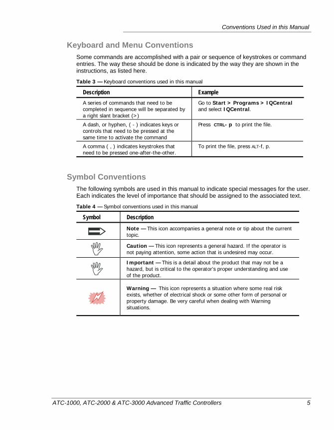
Symbol Conventions The following symbols are used in this manual to indicate special messages for the user. Each indicates the level of importance that should be assigned to the associated text.
Table 4 — Symbol conventions used in this manual
Symbol Description
Note — This icon accompanies a general note or tip about the current topic.
Caution — This icon represents a general hazard. If the operator is not paying attention, some action that is undesired may occur.
Important — This is a detail about the product that may not be a hazard, but is critical to the operator’s proper understanding and use of the product.
Warning — This icon represents a situation where some real risk exists, whether of electrical shock or some other form of personal or property damage. Be very careful when dealing with Warning situations.

Preface — About This Manual
6 ATC-1000, ATC-2000 & ATC-3000 Advanced Traffic Controllers
ATC-1000, ATC-2000 & ATC-3000 Advanced Traffic Controllers 7
Chapter 1 — Introduction to the ATC Controllers
This chapter introduces the components, firmware and utility software of the Peek ATC Traffic Controllers. The following topics are discussed in detail in this chapter:
• An overview of the controller, starting on page 8.
• Details about the parts and controls of an ATC controller, page 13.
• An intro to the basic operation of the controller, on page 24.
• An introduction to the ATC Link software utility, on page 38.
• Introduction to IQ Central, on page 39.
Chapter 1 — Introduction to the ATC Controllers
8 ATC-1000, ATC-2000 & ATC-3000 Advanced Traffic Controllers
OVERVIEW OF THE CONTROLLERS
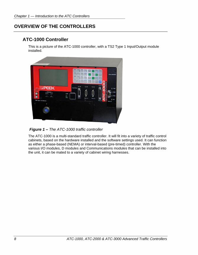
ATC-1000 Controller This is a picture of the ATC-1000 controller, with a TS2 Type 1 Input/Output module installed.
Figure 1 – The ATC-1000 traffic controller
The ATC-1000 is a multi-standard traffic controller. It will fit into a variety of traffic control cabinets, based on the hardware installed and the software settings used. It can function as either a phase-based (NEMA) or interval-based (pre-timed) controller. With the various I/O modules, D modules and Communications modules that can be installed into the unit, it can be mated to a variety of cabinet wiring harnesses.
Conventions Used in this Manual
ATC-1000, ATC-2000 & ATC-3000 Advanced Traffic Controllers 9
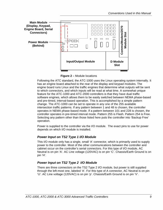
Figure 2 – Module locations
Following the ATC standard, the ATC-1000 uses the Linux operating system internally. It has an engine board attached to the rear of the display and keypad modules. The engine board runs Linux and the traffic engines that determine what outputs will be sent to which connectors, and which inputs will be read at what time. A somewhat unique feature for the ATC-1000 and ATC-2000 controllers is that they have dual traffic software engines, which allows them to be easily switched between NEMA phase-based and pre-timed, interval-based operation. This is accomplished by a simple pattern change. The ATC-1000 can be set to operate in any one of the 255 available intersection traffic patterns. If any pattern between 1 and 48 is chosen, the controller operates in NEMA phase-based mode. If a pattern between 101 and 228 is chosen, the controller operates in pre-timed interval mode. Pattern 255 is Flash. Pattern 254 is Free. Selecting any pattern other than those listed here puts the controller into ‘Backup Free’ operation.
Power is supplied to the controller via the I/O module. The exact pins to use for power depends on which I/O module is installed.
Power Input on TS2 Type 1 I/O Module This I/O module only has a single, small ‘A’ connector, which is primarily used to supply power to the controller. Most of the other communications between the controller and cabinet occur on the controller’s serial connectors. For this type of I/O module, AC Neutral is on pin ‘A’. AC Line voltage (120VAC) is on pin ‘C’. Chassis/Earth Ground is on pin ‘H’.
Power Input on TS2 Type 2 I/O Module There are three connectors on the TS2 Type 2 I/O module, but power is still supplied through the left-most one, labeled ‘A’. For this type of A connector, AC Neutral is on pin ‘U’. AC Line voltage (120VAC) is on pin ‘p’. Chassis/Earth Ground is on pin ‘V’.
Input/Output Module D Module Slot
Com
ms/
Mod
em/2
070
Mod
ule
Slot
Main Module(Display, Keypad,
Engine Board, Serial Connectors)
Power Module(Behind)
Chapter 1 — Introduction to the ATC Controllers
10 ATC-1000, ATC-2000 & ATC-3000 Advanced Traffic Controllers
Power Input on LMD I/O Module The LMD I/O module has two connectors, A and B, but power is yet again supplied on the ‘A’ connector. For the LMD A connector, AC Line voltage (120VAC) is supplied on pin ‘p’. AC Neutral is on pin ‘U’, and Chassis/Earth Ground is on pin ‘V’
Power Input on HMC-1000 I/O Module The HMC controllers were a line of devices manufactured by Honeywell Corporation in the 1970s and 1980s. They were among the earliest traffic controllers that implemented the NEMA TS1 standard. The HMC-1000 I/O module has 1 connector and a switch. The main connector is labeled connector ‘INPUT/OUTPUT’ and it has AC Line voltage (120VAC) supplied on pin 61. AC Neutral is on pin 62, and Chassis/Earth Ground is on pin 63.
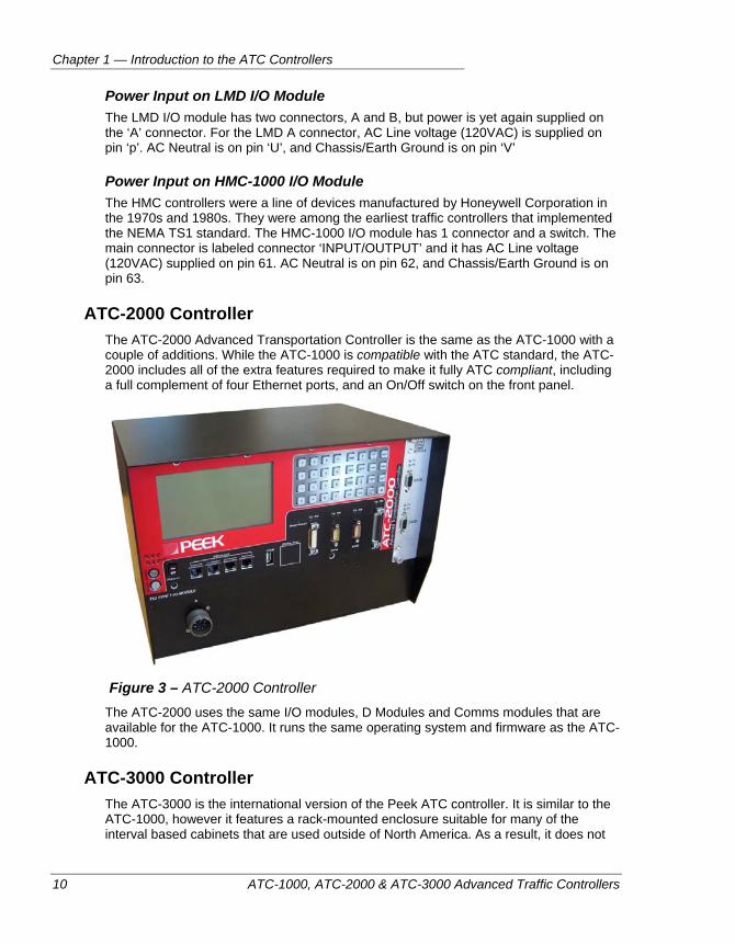
ATC-2000 Controller The ATC-2000 Advanced Transportation Controller is the same as the ATC-1000 with a couple of additions. While the ATC-1000 is compatible with the ATC standard, the ATC-2000 includes all of the extra features required to make it fully ATC compliant, including a full complement of four Ethernet ports, and an On/Off switch on the front panel.
Figure 3 – ATC-2000 Controller
The ATC-2000 uses the same I/O modules, D Modules and Comms modules that are available for the ATC-1000. It runs the same operating system and firmware as the ATC-1000.
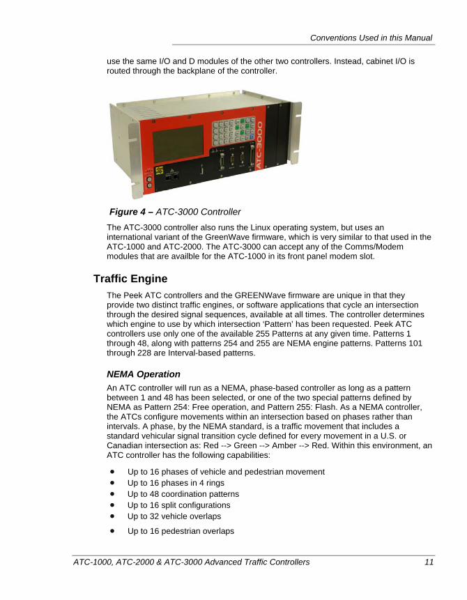
ATC-3000 Controller The ATC-3000 is the international version of the Peek ATC controller. It is similar to the ATC-1000, however it features a rack-mounted enclosure suitable for many of the interval based cabinets that are used outside of North America. As a result, it does not
Conventions Used in this Manual
ATC-1000, ATC-2000 & ATC-3000 Advanced Traffic Controllers 11
use the same I/O and D modules of the other two controllers. Instead, cabinet I/O is routed through the backplane of the controller.
Figure 4 – ATC-3000 Controller
The ATC-3000 controller also runs the Linux operating system, but uses an international variant of the GreenWave firmware, which is very similar to that used in the ATC-1000 and ATC-2000. The ATC-3000 can accept any of the Comms/Modem modules that are availble for the ATC-1000 in its front panel modem slot.
Traffic Engine The Peek ATC controllers and the GREENWave firmware are unique in that they provide two distinct traffic engines, or software applications that cycle an intersection through the desired signal sequences, available at all times. The controller determines which engine to use by which intersection ‘Pattern’ has been requested. Peek ATC controllers use only one of the available 255 Patterns at any given time. Patterns 1 through 48, along with patterns 254 and 255 are NEMA engine patterns. Patterns 101 through 228 are Interval-based patterns.
NEMA Operation An ATC controller will run as a NEMA, phase-based controller as long as a pattern between 1 and 48 has been selected, or one of the two special patterns defined by NEMA as Pattern 254: Free operation, and Pattern 255: Flash. As a NEMA controller, the ATCs configure movements within an intersection based on phases rather than intervals. A phase, by the NEMA standard, is a traffic movement that includes a standard vehicular signal transition cycle defined for every movement in a U.S. or Canadian intersection as: Red --> Green --> Amber --> Red. Within this environment, an ATC controller has the following capabilities:
Up to 16 phases of vehicle and pedestrian movement Up to 16 phases in 4 rings Up to 48 coordination patterns Up to 16 split configurations Up to 32 vehicle overlaps
Up to 16 pedestrian overlaps
Chapter 1 — Introduction to the ATC Controllers
12 ATC-1000, ATC-2000 & ATC-3000 Advanced Traffic Controllers
Up to 6 preemption plans Up to 64 vehicle detector inputs Up to 8 pedestrian detector inputs Up to 48 Time of Day action plans Up to 32 Time of Day day plans Up to 32 Time of Day schedules The ability to communicate with a Central System via the NTCIP protocol
The ATC controllers use the US Department of Transportation sponsored and ITE (Institute of Transportation Engineers) published Advanced Transportation Controller standard. The physical connections that are made to the cabinet depend on which I/O and D Modules have been installed in the unit. The ATC can be configured to use TS2 Type 1, TS2 Type 2, HMC-1000, or LMD connections. Available D modules are: Closed Loop (3000E), LMD9200, Traconex and Multisonics.
Interval-based Operation The ATC controllers will run interval-based patterns as long as a pattern between 101 and 228 is selected. Interval-based operation is used by most of the world other than the United States and Canada, and even in those two countries, some cities, states, and provinces use interval-based programming rather than NEMA programming. An interval is defined as a period of time during which all of the signal outputs generated by the controller are in a fixed state. Whenever any signal output needs to change, that marks the beginning of a new interval. Although originally a simpler programming methodology, Interval-based operation has evolved to include many features that have long been standard in phase-based operation, including preemption, TSP operation, and detector actuation.
Transitioning Between NEMA and Interval-Based Operation Any time that the controller will be asked to switch between NEMA and Interval-based operation, or vice versa, the controller will manage the interface between the two very differing modes of operation by transitioning into and out of the Red Rest state.1 Both NEMA and Interval-based operation recognize the Red Rest state, and both can have transition sequences defined to enter and leave Red Rest. Peek ATC controllers utilize this area of commonality to decide where a safe transition can take place. This enables a traffic engine transition without the need to send the intersection into the Flash state.
Cabinet Environment Peek ATC controllers, as long as they are is fitted with the proper type of I/O module and firmware, can function as controller replacements in any cabinets that currently host: interval-based, NEMA TS1, TS2 Type 1, TS2 Type 2, HMC-1000, LMD 40, LMD 9200, Traconex, or Multisonics traffic controller.
1 Patent pending.
Controller Hardware
ATC-1000, ATC-2000 & ATC-3000 Advanced Traffic Controllers 13
CONTROLLER HARDWARE
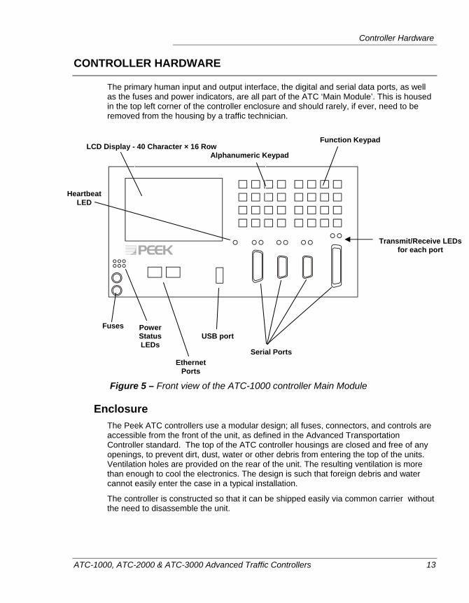
The primary human input and output interface, the digital and serial data ports, as well as the fuses and power indicators, are all part of the ATC ‘Main Module’. This is housed in the top left corner of the controller enclosure and should rarely, if ever, need to be removed from the housing by a traffic technician.
Figure 5 – Front view of the ATC-1000 controller Main Module
Enclosure The Peek ATC controllers use a modular design; all fuses, connectors, and controls are accessible from the front of the unit, as defined in the Advanced Transportation Controller standard. The top of the ATC controller housings are closed and free of any openings, to prevent dirt, dust, water or other debris from entering the top of the units. Ventilation holes are provided on the rear of the unit. The resulting ventilation is more than enough to cool the electronics. The design is such that foreign debris and water cannot easily enter the case in a typical installation.
The controller is constructed so that it can be shipped easily via common carrier without the need to disassemble the unit.
LCD Display - 40 Character × 16 Row
Fuses USB port
Serial Ports Ethernet
Ports
Heartbeat LED
Alphanumeric Keypad
Function Keypad
Transmit/Receive LEDs for each port
Power Status LEDs
Chapter 1 — Introduction to the ATC Controllers
14 ATC-1000, ATC-2000 & ATC-3000 Advanced Traffic Controllers
Operating System, Firmware and Memory When an ATC controller is powered on, it loads a copy of the Linux operating system from BIOS into flash memory and runs it. The operating system then loads the programming and parameters it needs to operate.
The controller’s basic functionality is defined by its programming. This programming is maintained as data in non-volatile flash memory. Firmware can be stored or updated in the unit in a couple of ways. It can be stored to internal flash memory either from a USB drive via the USB port at the front of the unit, or through the Ethernet port via an attached Microsoft Windows PC that is running the ATCLink software utility.
The controller’s ‘database’ is its set of operating parameters that tell the software exactly what type of intersection is being controlled. This database can be loaded in three possible ways: via the USB port, via an Ethernet connection to a PC running ATCLink, or via a comms link to a central system software package such as IQ Central.
The controller’s Linux operating system continuously checks the integrity of the unit’s internal memory, the loaded firmware, and the local database of configured parameters. If the controller detects a fault, it will immediately terminate its watchdog output (i.e. CVM or Fault Monitor) to the CMU or MMU, which will then place the cabinet and the intersection into FLASH mode. When this situation occurs, the controller’s display shows a message indicating the cause of the failure, and at the same time information is recorded to the controller’s event log detailing the date, time and type of error that has occurred.
Display The front panel display of the controller is a 40 character wide by 16 row tall LCD screen. The display shows the ATC’s menu system, its currently configured parameters, and status screens that display the current situation within the controller and in the intersection.
The display is fully operable over the temperature range of –4 to +158°F (–20 to +70° C). Below 32°F (0°C) a heater comes on to warm the display, but only when the cabinet door is open. The display would not be damaged by such lower temperatures without the heater, however the screen might not display properly. The heating function is automatic, as long as the cabinet open signal has been properly routed to the controller inputs.
Contrast Control The liquid crystal display has a user configurable contrast setting. To modify the contrast of the screen, the power to the unit must be on and it must be beyond its initial startup
routine. Press the blue function key on the controller’s keypad (located at the bottom right corner of the keypad), then use the contrast up and contrast down keys to
change the screen display. Contrast Up = . Contrast Down = .
Controller Hardware
ATC-1000, ATC-2000 & ATC-3000 Advanced Traffic Controllers 15
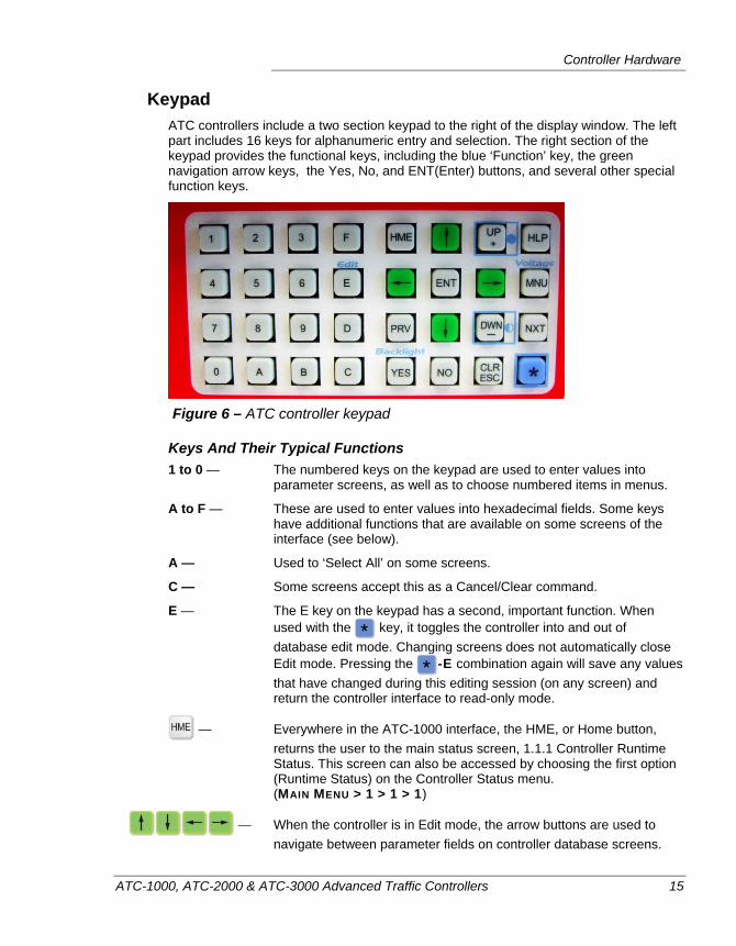
Keypad ATC controllers include a two section keypad to the right of the display window. The left part includes 16 keys for alphanumeric entry and selection. The right section of the keypad provides the functional keys, including the blue ‘Function’ key, the green navigation arrow keys, the Yes, No, and ENT(Enter) buttons, and several other special function keys.
Figure 6 – ATC controller keypad
Keys And Their Typical Functions 1 to 0 — The numbered keys on the keypad are used to enter values into
parameter screens, as well as to choose numbered items in menus.
A to F — These are used to enter values into hexadecimal fields. Some keys have additional functions that are available on some screens of the interface (see below).
A — Used to ‘Select All’ on some screens.
C — Some screens accept this as a Cancel/Clear command.
E — The E key on the keypad has a second, important function. When used with the key, it toggles the controller into and out of database edit mode. Changing screens does not automatically close Edit mode. Pressing the -E combination again will save any values that have changed during this editing session (on any screen) and return the controller interface to read-only mode.
— Everywhere in the ATC-1000 interface, the HME, or Home button, returns the user to the main status screen, 1.1.1 Controller Runtime Status. This screen can also be accessed by choosing the first option (Runtime Status) on the Controller Status menu. (MAIN MENU > 1 > 1 > 1)
— When the controller is in Edit mode, the arrow buttons are used to navigate between parameter fields on controller database screens.
Chapter 1 — Introduction to the ATC Controllers
16 ATC-1000, ATC-2000 & ATC-3000 Advanced Traffic Controllers
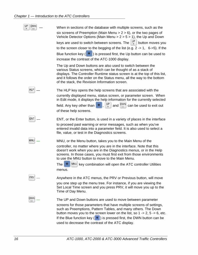
— When in sections of the database with multiple screens, such as the six screens of Preemption (Main Menu > 2 > 6), or the two pages of Vehicle Detector Options (Main Menu > 2 > 5 > 1), the Up and Down
keys are used to switch between screens. The button moves you to the screen closer to the begging of the list (e.g. 2 -> 1, 6->5). If the
Blue function key ( ) is pressed first, the Up button can be used to increase the contrast of the ATC-1000 display.
The Up and Down buttons are also used to switch between the various Status screens, which can be thought of as a stack of displays. The Controller Runtime status screen is at the top of this list, and it follows the order on the Status menu, all the way to the bottom of the stack, the Revision Information screen.
— The HLP key opens the help screens that are associated with the currently displayed menu, status screen, or parameter screen. When in Edit mode, it displays the help information for the currently selected
field. Any key other than , and can be used to exit out of these help screens.
— ENT, or the Enter button, is used in a variety of places in the interface to proceed past warning or error messages, such as when you’ve entered invalid data into a parameter field. It is also used to select a file, value, or test in the Diagnostics screens.
— MNU, or the Menu button, takes you to the Main Menu of the controller, no matter where you are in the interface. Note that this doesn’t work when you are in the Diagnostics menus, or in the Help screens. In those cases, you must first exit from those environments to use the MNU button to move to the Main Menu.
The key combination will open the ATC controller Utilities menus.
— Anywhere in the ATC menus, the PRV or Previous button, will move you one step up the menu tree. For instance, if you are viewing the Set Local Time screen and you press PRV, it will move you up to the Time of Day Menu.
— The UP and Down buttons are used to move between parameter screens for those parameters that have multiple screens of settings, such as Preemptions, Pattern Tables, and many others. The Down button moves you to the screen lower on the list, so 1 -> 2, 5 -> 6, etc. If the Blue function key ( ) is pressed first, the DWN button can be used to decrease the contrast of the ATC display.
Controller Hardware
ATC-1000, ATC-2000 & ATC-3000 Advanced Traffic Controllers 17
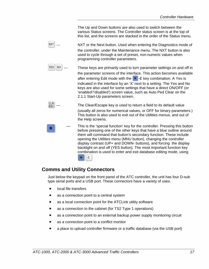
The Up and Down buttons are also used to switch between the various Status screens. The Controller status screen is at the top of this list, and the screens are stacked in the order of the Status menu.
— NXT or the Next button. Used when entering the Diagnostics mode of the controller, under the Maintenance menu. The NXT button is also used to cycle through a set of preset, non-numeric values when programming controller parameters.
— These keys are primarily used to turn parameter settings on and off in the parameter screens of the interface. This action becomes available after entering Edit mode with the -E key combination. A Yes is indicated in the interface by an ‘X’ next to a setting. The Yes and No keys are also used for some settings that have a direct ON/OFF (or ‘enabled’/’disabled’) screen value, such as Auto Ped Clear on the 2.1.1 Start-Up parameters screen.
— The Clear/Escape key is used to return a field to its default value (usually all zeros for numerical values, or OFF for binary parameters.) This button is also used to exit out of the Utilities menus, and out of the Help screens.
— This is the ‘special function’ key for the controller. Pressing this button before pressing one of the other keys that have a blue outline around them will command that button’s secondary function. These include opening the Utilities menu (MNU button), changing the controller display contrast (UP+ and DOWN- buttons), and forcing the display backlight on and off (YES button). The most important function key combination is used to enter and exit database editing mode, using
Comms and Utility Connectors Just below the keypad on the front panel of the ATC controller, the unit has four D-sub type serial ports and a USB port. These connectors have a variety of uses.
local file transfers
as a connection point to a central system
as a local connection point for the ATCLink utility software
as a connection to the cabinet (for TS2 Type 1 operations)
as a connection point to an external backup power supply monitoring circuit
as a connection point to a conflict monitor
a place to upload controller firmware or a traffic database (via the USB port)
Chapter 1 — Introduction to the ATC Controllers
18 ATC-1000, ATC-2000 & ATC-3000 Advanced Traffic Controllers
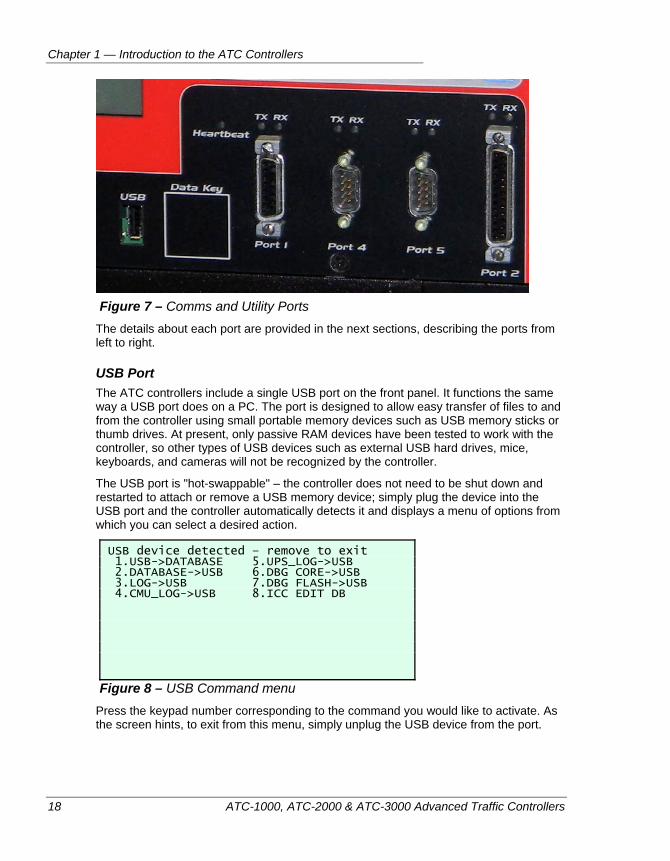
Figure 7 – Comms and Utility Ports
The details about each port are provided in the next sections, describing the ports from left to right.
USB Port The ATC controllers include a single USB port on the front panel. It functions the same way a USB port does on a PC. The port is designed to allow easy transfer of files to and from the controller using small portable memory devices such as USB memory sticks or thumb drives. At present, only passive RAM devices have been tested to work with the controller, so other types of USB devices such as external USB hard drives, mice, keyboards, and cameras will not be recognized by the controller.
The USB port is "hot-swappable" – the controller does not need to be shut down and restarted to attach or remove a USB memory device; simply plug the device into the USB port and the controller automatically detects it and displays a menu of options from which you can select a desired action.
USB device detected – remove to exit 1.USB->DATABASE 5.UPS_LOG->USB 2.DATABASE->USB 6.DBG CORE->USB 3.LOG->USB 7.DBG FLASH->USB 4.CMU_LOG->USB 8.ICC EDIT DB
Figure 8 – USB Command menu Press the keypad number corresponding to the command you would like to activate. As the screen hints, to exit from this menu, simply unplug the USB device from the port.
Controller Hardware
ATC-1000, ATC-2000 & ATC-3000 Advanced Traffic Controllers 19
Port 1 - SDLC Port 1 is an RS-485 port (now known as an EIA-485 differential serial communications interface.) This port is used in a TS2 cabinet to communicate with other devices within the cabinet. Typically, TS2 Type 2 controllers use the SDLC port to connect to the intersection MMU.
The 15 pin female port uses the SDLC (synchronous data link) communication protocol with a bit rate of 153.6 Kbps, as required by the NEMA TS2-2008 Standard. This port’s TX LED is on whenever the controller is transmitting data. The RX LED is on whenever the controller receives data on this port.
The port’s high speed full duplex data channels utilize four twisted pairs: two transmit and receive data pairs, and two transmit and receive clock pairs. The pin assignments for Port 1 are detailed on page 308.
Port 4 - Local The Local port, or Port 4 on an ATC controller front panel is a male 9-pin serial port that is often used to connect a Conflict Monitor (CMU) or Malfunction Monitor (MMU) to the controller. The data rates for this port are firmware-selectable from 1200 bps to 115.2 Kbps. Parity (Odd, Even, None), Stop Bit (1 or 2), and Handshake (None, Xon/Xoff, Hardware) can also be set for this port in the controller firmware. This port is also often used as the connection point to directly attach a PC that is running ATCLink, thus allowing firmware updates and on-site database modifications.
Just as with Port 1, this port’s TX LED lights whenever the controller is transmitting data, and the RX LED lights whenever it is receiving data on this port. The pin assignments for Port 4 are detailed on page 311.
Port 5 – UPS/Spare Port 5, or the ‘Spare’ port, is a 9 pin male RS-232 port that is typically used to connect a data cable from a cabinet UPS system to the controller, or it can be used to connect a PC directly to the controller via a standard serial cable (for example, to use it with ATCLink.) Port 5 can also be used as a connection point to the central software system.
The TX LED indicates when the controller is transmitting data and the RX LED indicates when it’s receiving data on the port. The pin assignments for Port 5 are detailed on page 312.
Port 2 - Central Port 2 is a 25 pin female connector. Port 2 is also known as the Central Port, and is often used to connect the controller to a central software system such as IQ Central, either via a direct serial connection, or via a modem (e.g. TELCO, fiber optic, or radio modems). This is the standard port used to connect to a central system software package when connecting via direct serial or a modem. The port can be configured in firmware and will support transmission speeds up to 115.2K bps. Port 2, Port 5, and the Ethernet ports are the only ports that fully support the NTCIP protocol.
Standard serial communications are supported with speeds from 1200 bps to 115.2 Kbps, as well as Parity (Odd, Even, None), Stop Bit (1 or 2), and Handshake (None, Xon/Xoff, Hardware) settings.
Chapter 1 — Introduction to the ATC Controllers
20 ATC-1000, ATC-2000 & ATC-3000 Advanced Traffic Controllers
Port 2’s TX LED goes on whenever the controller is transmitting data and the RX LED goes on whenever the controller is receiving data on the port.
The pin assignments for Port 2 are detailed on page 309.
Ethernet Ports The ATC-1000 has two RJ-45 Ethernet ports. The ATC-2000 controller comes with four Ethernet ports, as specified in the FHWA ATC standard. The Ethernet ports all use the standard 10/100Base-T network interface, and conform to the IEEE 802.3 standard for twisted pair communications. The network interface supports transmission at the full 100Mbps rate. Each ATC controller has a unique MAC network address, which can be viewed in the firmware interface by choosing the Revision Information screen under the Status menu (MAIN MENU > 1. STATUS > 5. REVISIONS). The port supports communications using either TCP/IP, SNMP, or NTCIP networking protocols. The Ethernet connectors and Ports 2 and 5 are the only ports that can be used to connect the ATC-1000 controller to a central server software system, such as IQCentral.
Unlike the other ports on the front of the ATC controller, which indicate Transmit (TX) and Receive (RX) status via their LEDs, the Ethernet ports have built in LEDs that indicate status in a slightly different way. The yellow “LINK” LED (in the bottom left corner of the connector) indicates when the Ethernet port is connected to an active Ethernet hub/switch or computer (i.e. something outside of the controller has acknowledged that the port is on the network,) and that the controller is ready to transmit and receive data on that network. The green “ACT” LED (in the bottom right corner of the port) shows when the port is being used to actually transmit and receive data.
Optional Expansion Slot Ports Along the right edge of the unit, the ATC Controllers have a vacant slot available behind a removable front panel. This slot can accommodate any of the comms modules available for the Peek 3000E controllers, including the 3000E fiber optic module and the FSK Modem. The connector in the slot is the 96 socket contact DIN 41612 as specified in the CalTrans TEES – 1999 to support a 2X wide board. The serial ports that result from installing these cards can be configured in the firmware to support transmission speeds of from 1200 bps up to 115.2 Kbps. The firmware can also be used to set the Parity (Odd, Even, None), Stop Bit (1 or 2), and Handshake (None, Xon/Xoff, Hardware) settings for these ports. The pin assignments for these cards are available in the documentation provided with those optional add-on cards.
Controller Hardware
ATC-1000, ATC-2000 & ATC-3000 Advanced Traffic Controllers 21
I/O Module Connectors
Note This whole topic pertains to the ATC-1000 and ATC-2000 controllers only. The ATC-3000 controller uses a dedicated backplane I/O.
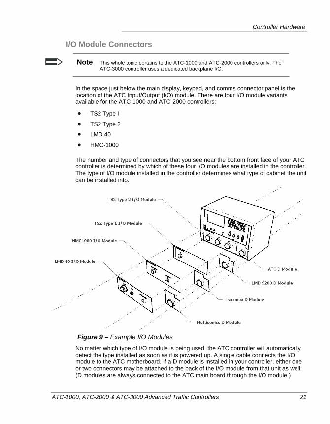
In the space just below the main display, keypad, and comms connector panel is the location of the ATC Input/Output (I/O) module. There are four I/O module variants available for the ATC-1000 and ATC-2000 controllers:
TS2 Type I
TS2 Type 2
LMD 40
HMC-1000
The number and type of connectors that you see near the bottom front face of your ATC controller is determined by which of these four I/O modules are installed in the controller. The type of I/O module installed in the controller determines what type of cabinet the unit can be installed into.
Figure 9 – Example I/O Modules
No matter which type of I/O module is being used, the ATC controller will automatically detect the type installed as soon as it is powered up. A single cable connects the I/O module to the ATC motherboard. If a D module is installed in your controller, either one or two connectors may be attached to the back of the I/O module from that unit as well. (D modules are always connected to the ATC main board through the I/O module.)
Chapter 1 — Introduction to the ATC Controllers
22 ATC-1000, ATC-2000 & ATC-3000 Advanced Traffic Controllers
The pin assignments and voltage and current requirements of the various I/O module connectors are defined in “Chapter 9 — Overlaps”, starting on page 241.
Heartbeat LED The front panel includes a “Heartbeat” LED, which flashes at a rate of four times per second as long as the controller’s internal fault monitor signal is being generated and the traffic engine is running. If the controller is powered ON, but has a serious problem, the blinking of this LED will halt completely, meaning that the LED will stay on in an unblinking state.
Data Key Port A Data Key port is part of the FHWA ATC standard and is known as a ‘keyceptical’. This port is available as an option on all of the ATC controllers. The actual ‘key’ that is used in these ports is a non-volatile computer memory device that can be used to store controller database (i.e. traffic programming) and conflict monitor programming card settings. It functions in much the same way that a USB drive does when inserted into the ATC’s USB port, with one additional feature. If the data key has CMU or MMU programming information stored on it, the controller and conflict monitor will interact to verify that the conflict matrix defined therein is valid and compatible.
Figure 10 – Datakey type data receptacle
Compatible data keys are available from DataKey Electronics, Inc. of Minneapolis, Minnesota. (www.datakeyelectronics.com). The ATC controllers will accept SFK series SPI 5V Flash & EEPROM type serial memory keys.
Power System The ATC-1000 and ATC-2000 controllers are powered through the I/O Module. The ATC-3000 is powered through the backplane. The exact port and pins used to provide power to the controller depends on which I/O module is being used, but it is typically the left most port on the module, which is called the “A” connector on the TS2 I/O modules. For instance, on a TS2 Type 2 I/O module, power comes in by accepting 120VAC on pin p and AC neutral on pin U.
There is no internal battery backup for memory storage or the real time clock in the ATC controllers. During power down or power outages, all static memory (SRAM) and the real-time clock are powered by two super capacitors. In the event of an AC power
Controller Hardware
ATC-1000, ATC-2000 & ATC-3000 Advanced Traffic Controllers 23
outage, these capacitors provide sufficient power to maintain the SRAM contents and the functioning of the real time clock for up to seven days.
AC power goes to a power module, located behind the front face of the main controller module, along the left side of the controller. The power LEDs and fuses on the front panel of the controller are actually part of the ATC power module.
Fuses The controller is fitted with a pair of easily replaced front panel power fuses. These are located in the lower left corner of the main display/keyboard module.
The bottom fuse is a 1 Amp fuse that protects the internal circuitry of the controller from excess current coming into the unit via main AC power. The top fuse protects the controller from over-current situations occurring on the Fault Monitor output pin of the I/O module connectors. For example, on the TS2 Type 2 I/O module, this output is located on pin A of the MS-A connector. No matter which I/O module is connected, this fuse is designed to blow if the 24VDC output exceeds 1 Amp of current.
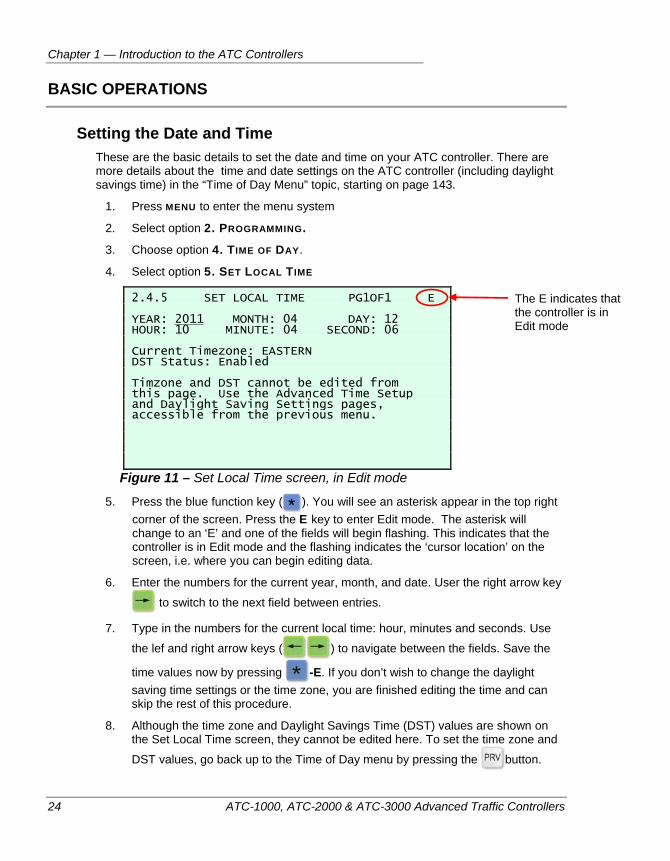
Chapter 1 — Introduction to the ATC Controllers
24 ATC-1000, ATC-2000 & ATC-3000 Advanced Traffic Controllers
BASIC OPERATIONS
Setting the Date and Time These are the basic details to set the date and time on your ATC controller. There are more details about the time and date settings on the ATC controller (including daylight savings time) in the “Time of Day Menu” topic, starting on page 143.
1. Press MENU to enter the menu system
2. Select option 2. PROGRAMMING.
3. Choose option 4. TIME OF DAY.
4. Select option 5. SET LOCAL TIME
2.4.5 SET LOCAL TIME PG1OF1 E YEAR: 2011 MONTH: 04 DAY: 12 HOUR: 10 MINUTE: 04 SECOND: 06 Current Timezone: EASTERN DST Status: Enabled Timzone and DST cannot be edited from this page. Use the Advanced Time Setup and Daylight Saving Settings pages, accessible from the previous menu.
Figure 11 – Set Local Time screen, in Edit mode
5. Press the blue function key ( ). You will see an asterisk appear in the top right corner of the screen. Press the E key to enter Edit mode. The asterisk will change to an ‘E’ and one of the fields will begin flashing. This indicates that the controller is in Edit mode and the flashing indicates the ‘cursor location’ on the screen, i.e. where you can begin editing data.
6. Enter the numbers for the current year, month, and date. User the right arrow key
to switch to the next field between entries.
7. Type in the numbers for the current local time: hour, minutes and seconds. Use
the lef and right arrow keys ( ) to navigate between the fields. Save the
time values now by pressing -E. If you don’t wish to change the daylight saving time settings or the time zone, you are finished editing the time and can skip the rest of this procedure.
8. Although the time zone and Daylight Savings Time (DST) values are shown on the Set Local Time screen, they cannot be edited here. To set the time zone and
DST values, go back up to the Time of Day menu by pressing the button.
The E indicates that the controller is in Edit mode
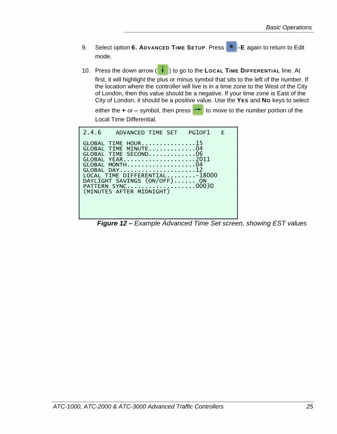
Basic Operations
ATC-1000, ATC-2000 & ATC-3000 Advanced Traffic Controllers 25
9. Select option 6. ADVANCED TIME SETUP. Press -E again to return to Edit mode.
10. Press the down arrow ( ) to go to the LOCAL TIME DIFFERENTIAL line. At first, it will highlight the plus or minus symbol that sits to the left of the number. If the location where the controller will live is in a time zone to the West of the City of London, then this value should be a negative. If your time zone is East of the City of London, it should be a positive value. Use the YES and NO keys to select
either the + or – symbol, then press to move to the number portion of the Local Time Differential.
2.4.6 ADVANCED TIME SET PG1OF1 E GLOBAL TIME HOUR...............15 GLOBAL TIME MINUTE.............04 GLOBAL TIME SECOND.............06 GLOBAL YEAR....................2011 GLOBAL MONTH...................04 GLOBAL DAY.....................12 LOCAL TIME DIFFERENTIAL........-18000 DAYLIGHT SAVINGS (ON/OFF)...... ON PATTERN SYNC...................00030 (MINUTES AFTER MIDNIGHT)
Figure 12 – Example Advanced Time Set screen, showing EST values
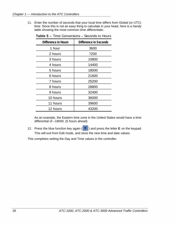
Chapter 1 — Introduction to the ATC Controllers
26 ATC-1000, ATC-2000 & ATC-3000 Advanced Traffic Controllers
11. Enter the number of seconds that your local time differs from Global (or UTC) time. Since this is not an easy thing to calculate in your head, here is a handy table showing the most common time differentials:
Table 5 – Time Conversions – Seconds to Hours
Difference in Hours Difference in Seconds 1 hour 3600
2 hours 7200
3 hours 10800
4 hours 14400
5 hours 18000
6 hours 21600
7 hours 25200
8 hours 28800
9 hours 32400
10 hours 36000
11 hours 39600
12 hours 43200
As an example, the Eastern time zone in the United States would have a time differential of –18000. (5 hours ahead)
12. Press the blue function key again ( ) and press the letter E on the keypad. This will exit from Edit mode, and store the new time and date values.
This completes setting the Day and Time values in the controller.
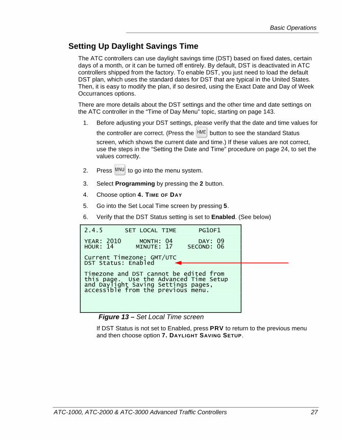
Basic Operations
ATC-1000, ATC-2000 & ATC-3000 Advanced Traffic Controllers 27
Setting Up Daylight Savings Time The ATC controllers can use daylight savings time (DST) based on fixed dates, certain days of a month, or it can be turned off entirely. By default, DST is deactivated in ATC controllers shipped from the factory. To enable DST, you just need to load the default DST plan, which uses the standard dates for DST that are typical in the United States. Then, it is easy to modify the plan, if so desired, using the Exact Date and Day of Week Occurrances options.
There are more details about the DST settings and the other time and date settings on the ATC controller in the “Time of Day Menu” topic, starting on page 143.
1. Before adjusting your DST settings, please verify that the date and time values for
the controller are correct. (Press the button to see the standard Status screen, which shows the current date and time.) If these values are not correct, use the steps in the “Setting the Date and Time” procedure on page 24, to set the values correctly.
2. Press to go into the menu system.
3. Select Programming by pressing the 2 button.
4. Choose option 4. TIME OF DAY
5. Go into the Set Local Time screen by pressing 5.
6. Verify that the DST Status setting is set to Enabled. (See below)
2.4.5 SET LOCAL TIME PG1OF1 YEAR: 2010 MONTH: 04 DAY: 09 HOUR: 14 MINUTE: 17 SECOND: 06 Current Timezone: GMT/UTC DST Status: Enabled Timezone and DST cannot be edited from this page. Use the Advanced Time Setup and Daylight Saving Settings pages, accessible from the previous menu.
Figure 13 – Set Local Time screen If DST Status is not set to Enabled, press PRV to return to the previous menu
and then choose option 7. DAYLIGHT SAVING SETUP.
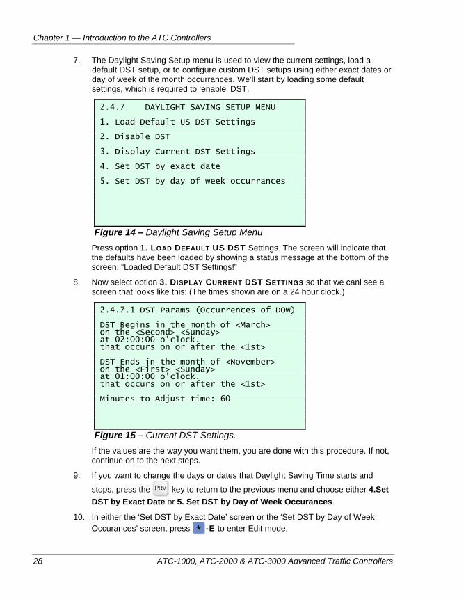
Chapter 1 — Introduction to the ATC Controllers
28 ATC-1000, ATC-2000 & ATC-3000 Advanced Traffic Controllers
7. The Daylight Saving Setup menu is used to view the current settings, load a default DST setup, or to configure custom DST setups using either exact dates or day of week of the month occurrances. We’ll start by loading some default settings, which is required to ‘enable’ DST.
2.4.7 DAYLIGHT SAVING SETUP MENU 1. Load Default US DST Settings 2. Disable DST 3. Display Current DST Settings 4. Set DST by exact date 5. Set DST by day of week occurrances
Figure 14 – Daylight Saving Setup Menu Press option 1. LOAD DEFAULT US DST Settings. The screen will indicate that
the defaults have been loaded by showing a status message at the bottom of the screen: “Loaded Default DST Settings!”
8. Now select option 3. DISPLAY CURRENT DST SETTINGS so that we canl see a screen that looks like this: (The times shown are on a 24 hour clock.)
2.4.7.1 DST Params (Occurrences of DOW) DST Begins in the month of <March> on the <Second> <Sunday> at 02:00:00 o’clock. that occurs on or after the <1st> DST Ends in the month of <November> on the <First> <Sunday> at 01:00:00 o’clock. that occurs on or after the <1st> Minutes to Adjust time: 60
Figure 15 – Current DST Settings. If the values are the way you want them, you are done with this procedure. If not,
continue on to the next steps.
9. If you want to change the days or dates that Daylight Saving Time starts and
stops, press the key to return to the previous menu and choose either 4.Set DST by Exact Date or 5. Set DST by Day of Week Occurances.
10. In either the ‘Set DST by Exact Date’ screen or the ‘Set DST by Day of Week Occurances’ screen, press -E to enter Edit mode.
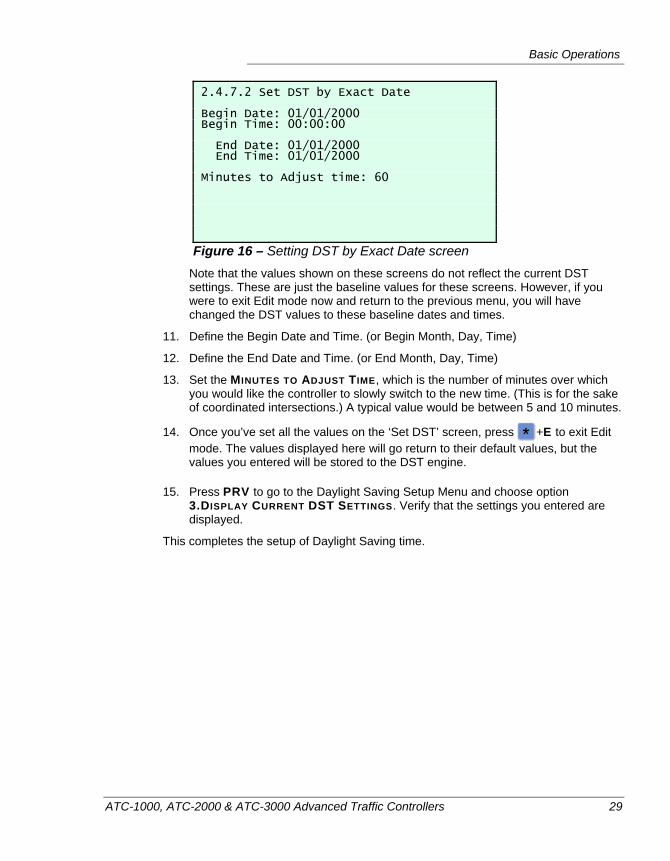
Basic Operations
ATC-1000, ATC-2000 & ATC-3000 Advanced Traffic Controllers 29
2.4.7.2 Set DST by Exact Date Begin Date: 01/01/2000 Begin Time: 00:00:00 End Date: 01/01/2000 End Time: 01/01/2000 Minutes to Adjust time: 60
Figure 16 – Setting DST by Exact Date screen Note that the values shown on these screens do not reflect the current DST
settings. These are just the baseline values for these screens. However, if you were to exit Edit mode now and return to the previous menu, you will have changed the DST values to these baseline dates and times.
11. Define the Begin Date and Time. (or Begin Month, Day, Time)
12. Define the End Date and Time. (or End Month, Day, Time)
13. Set the MINUTES TO ADJUST TIME, which is the number of minutes over which you would like the controller to slowly switch to the new time. (This is for the sake of coordinated intersections.) A typical value would be between 5 and 10 minutes.
14. Once you’ve set all the values on the ‘Set DST’ screen, press +E to exit Edit mode. The values displayed here will go return to their default values, but the values you entered will be stored to the DST engine.
15. Press PRV to go to the Daylight Saving Setup Menu and choose option 3.DISPLAY CURRENT DST SETTINGS. Verify that the settings you entered are displayed.
This completes the setup of Daylight Saving time.
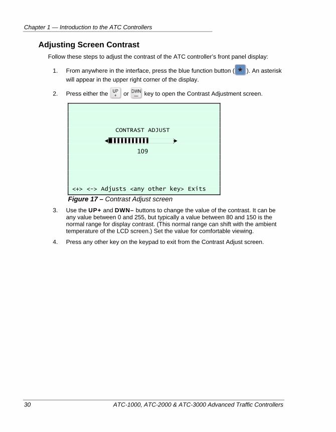
Chapter 1 — Introduction to the ATC Controllers
30 ATC-1000, ATC-2000 & ATC-3000 Advanced Traffic Controllers
Adjusting Screen Contrast Follow these steps to adjust the contrast of the ATC controller’s front panel display:
1. From anywhere in the interface, press the blue function button ( ). An asterisk will appear in the upper right corner of the display.
2. Press either the or key to open the Contrast Adjustment screen.
CONTRAST ADJUST ◄ ▌▌▌▌▌▌▌▌▌▌ ► 109 <+> <-> Adjusts <any other key> Exits
Figure 17 – Contrast Adjust screen 3. Use the UP+ and DWN– buttons to change the value of the contrast. It can be
any value between 0 and 255, but typically a value between 80 and 150 is the normal range for display contrast. (This normal range can shift with the ambient temperature of the LCD screen.) Set the value for comfortable viewing.
4. Press any other key on the keypad to exit from the Contrast Adjust screen.
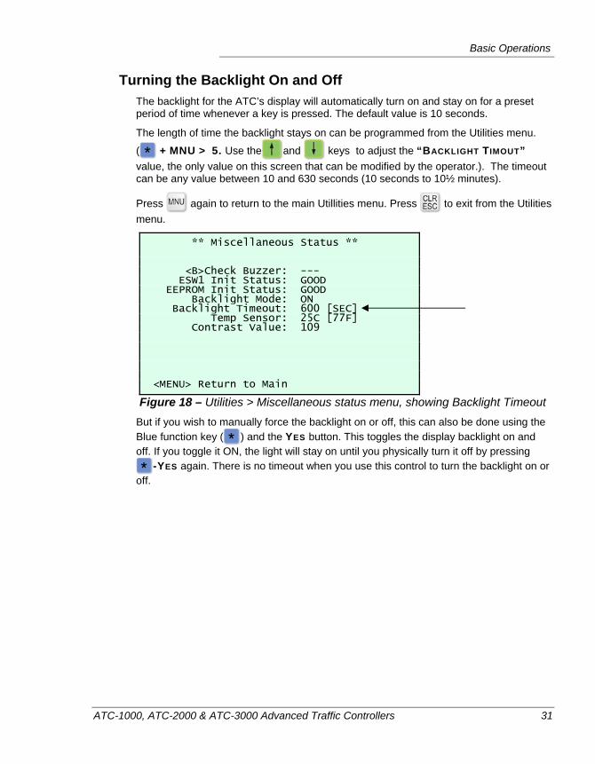
Basic Operations
ATC-1000, ATC-2000 & ATC-3000 Advanced Traffic Controllers 31
Turning the Backlight On and Off The backlight for the ATC’s display will automatically turn on and stay on for a preset period of time whenever a key is pressed. The default value is 10 seconds.
The length of time the backlight stays on can be programmed from the Utilities menu.
( + MNU > 5. Use the and keys to adjust the “BACKLIGHT TIMOUT” value, the only value on this screen that can be modified by the operator.). The timeout can be any value between 10 and 630 seconds (10 seconds to 10½ minutes).
Press again to return to the main Utillities menu. Press to exit from the Utilities menu.
** Miscellaneous Status ** <B>Check Buzzer: --- ESW1 Init Status: GOOD EEPROM Init Status: GOOD Backlight Mode: ON Backlight Timeout: 600 [SEC] Temp Sensor: 25C [77F] Contrast Value: 109 <MENU> Return to Main
Figure 18 – Utilities > Miscellaneous status menu, showing Backlight Timeout But if you wish to manually force the backlight on or off, this can also be done using the Blue function key ( ) and the YES button. This toggles the display backlight on and off. If you toggle it ON, the light will stay on until you physically turn it off by pressing
-YES again. There is no timeout when you use this control to turn the backlight on or off.
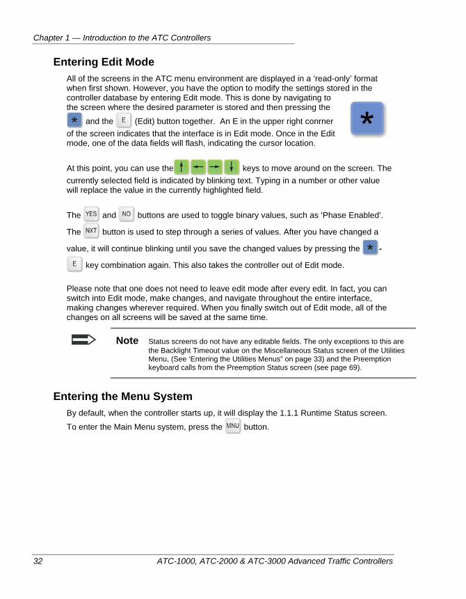
Chapter 1 — Introduction to the ATC Controllers
32 ATC-1000, ATC-2000 & ATC-3000 Advanced Traffic Controllers
Entering Edit Mode All of the screens in the ATC menu environment are displayed in a ‘read-only’ format when first shown. However, you have the option to modify the settings stored in the controller database by entering Edit mode. This is done by navigating to the screen where the desired parameter is stored and then pressing the
and the (Edit) button together. An E in the upper right conrner of the screen indicates that the interface is in Edit mode. Once in the Edit mode, one of the data fields will flash, indicating the cursor location.
At this point, you can use the keys to move around on the screen. The currently selected field is indicated by blinking text. Typing in a number or other value will replace the value in the currently highlighted field.
The and buttons are used to toggle binary values, such as ‘Phase Enabled’.
The button is used to step through a series of values. After you have changed a
value, it will continue blinking until you save the changed values by pressing the -
key combination again. This also takes the controller out of Edit mode.
Please note that one does not need to leave edit mode after every edit. In fact, you can switch into Edit mode, make changes, and navigate throughout the entire interface, making changes wherever required. When you finally switch out of Edit mode, all of the changes on all screens will be saved at the same time.
Note Status screens do not have any editable fields. The only exceptions to this are the Backlight Timeout value on the Miscellaneous Status screen of the Utilities Menu, (See ‘Entering the Utilities Menus” on page 33) and the Preemption keyboard calls from the Preemption Status screen (see page 69).
Entering the Menu System By default, when the controller starts up, it will display the 1.1.1 Runtime Status screen.
To enter the Main Menu system, press the button.
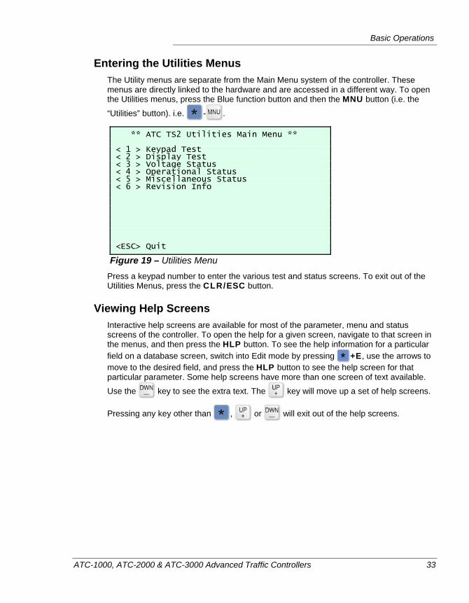
Basic Operations
ATC-1000, ATC-2000 & ATC-3000 Advanced Traffic Controllers 33
Entering the Utilities Menus The Utility menus are separate from the Main Menu system of the controller. These menus are directly linked to the hardware and are accessed in a different way. To open the Utilities menus, press the Blue function button and then the MNU button (i.e. the
“Utilities” button). i.e. - .
** ATC TS2 Utilities Main Menu ** < 1 > Keypad Test < 2 > Display Test < 3 > Voltage Status < 4 > Operational Status < 5 > Miscellaneous Status < 6 > Revision Info <ESC> Quit
Figure 19 – Utilities Menu Press a keypad number to enter the various test and status screens. To exit out of the Utilities Menus, press the CLR/ESC button.
Viewing Help Screens Interactive help screens are available for most of the parameter, menu and status screens of the controller. To open the help for a given screen, navigate to that screen in the menus, and then press the HLP button. To see the help information for a particular field on a database screen, switch into Edit mode by pressing +E, use the arrows to move to the desired field, and press the HLP button to see the help screen for that particular parameter. Some help screens have more than one screen of text available.
Use the key to see the extra text. The key will move up a set of help screens.
Pressing any key other than , or will exit out of the help screens.
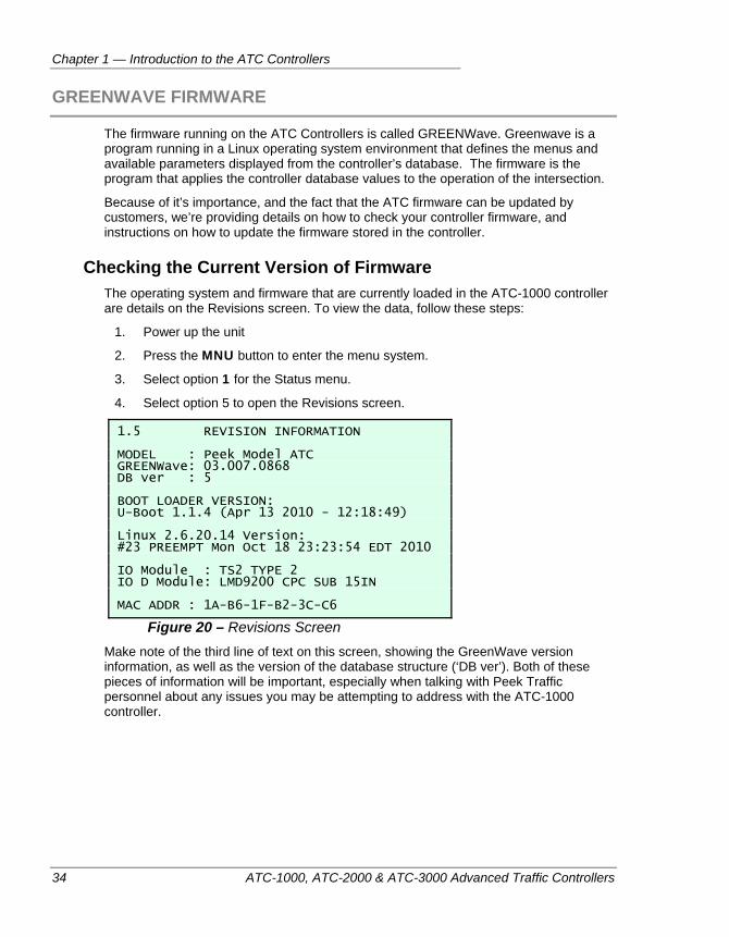
Chapter 1 — Introduction to the ATC Controllers
34 ATC-1000, ATC-2000 & ATC-3000 Advanced Traffic Controllers
GREENWAVE FIRMWARE
The firmware running on the ATC Controllers is called GREENWave. Greenwave is a program running in a Linux operating system environment that defines the menus and available parameters displayed from the controller’s database. The firmware is the program that applies the controller database values to the operation of the intersection.
Because of it’s importance, and the fact that the ATC firmware can be updated by customers, we’re providing details on how to check your controller firmware, and instructions on how to update the firmware stored in the controller.
Checking the Current Version of Firmware The operating system and firmware that are currently loaded in the ATC-1000 controller are details on the Revisions screen. To view the data, follow these steps:
1. Power up the unit
2. Press the MNU button to enter the menu system.
3. Select option 1 for the Status menu.
4. Select option 5 to open the Revisions screen.
1.5 REVISION INFORMATION MODEL : Peek Model ATC GREENWave: 03.007.0868 DB ver : 5 BOOT LOADER VERSION: U-Boot 1.1.4 (Apr 13 2010 - 12:18:49) Linux 2.6.20.14 Version: #23 PREEMPT Mon Oct 18 23:23:54 EDT 2010 IO Module : TS2 TYPE 2 IO D Module: LMD9200 CPC SUB 15IN MAC ADDR : 1A-B6-1F-B2-3C-C6
Figure 20 – Revisions Screen Make note of the third line of text on this screen, showing the GreenWave version information, as well as the version of the database structure (‘DB ver’). Both of these pieces of information will be important, especially when talking with Peek Traffic personnel about any issues you may be attempting to address with the ATC-1000 controller.
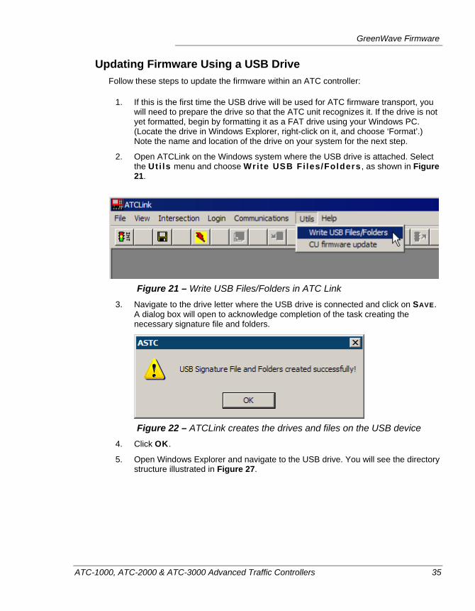
GreenWave Firmware
ATC-1000, ATC-2000 & ATC-3000 Advanced Traffic Controllers 35
Updating Firmware Using a USB Drive Follow these steps to update the firmware within an ATC controller:
1. If this is the first time the USB drive will be used for ATC firmware transport, you will need to prepare the drive so that the ATC unit recognizes it. If the drive is not yet formatted, begin by formatting it as a FAT drive using your Windows PC. (Locate the drive in Windows Explorer, right-click on it, and choose ‘Format’.) Note the name and location of the drive on your system for the next step.
2. Open ATCLink on the Windows system where the USB drive is attached. Select the Uti ls menu and choose Write USB Fi les/Folders , as shown in Figure 21.
Figure 21 – Write USB Files/Folders in ATC Link 3. Navigate to the drive letter where the USB drive is connected and click on SAVE.
A dialog box will open to acknowledge completion of the task creating the necessary signature file and folders.
Figure 22 – ATCLink creates the drives and files on the USB device 4. Click OK.
5. Open Windows Explorer and navigate to the USB drive. You will see the directory structure illustrated in Figure 27.
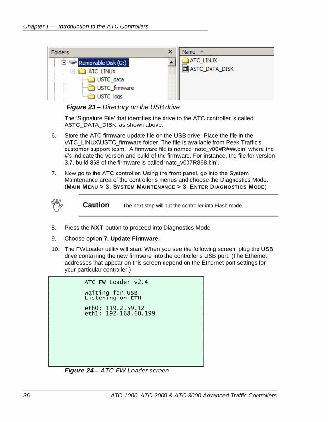
Chapter 1 — Introduction to the ATC Controllers
36 ATC-1000, ATC-2000 & ATC-3000 Advanced Traffic Controllers
Figure 23 – Directory on the USB drive The ‘Signature File’ that identifies the drive to the ATC controller is called
ASTC_DATA_DISK, as shown above.
6. Store the ATC firmware update file on the USB drive. Place the file in the \ATC_LINUX\USTC_firmware folder. The file is available from Peek Traffic’s customer support team. A firmware file is named ‘natc_v00#R###.bin’ where the #’s indicate the version and build of the firmware. For instance, the file for version 3.7, build 868 of the firmware is called ‘natc_v007R868.bin’.
7. Now go to the ATC controller. Using the front panel, go into the System Maintenance area of the controller’s menus and choose the Diagnostics Mode. (MAIN MENU > 3. SYSTEM MAINTENANCE > 3. ENTER DIAGNOSTICS MODE)
Caution The next step will put the controller into Flash mode.
8. Press the NXT button to proceed into Diagnostics Mode.
9. Choose option 7. Update Firmware.
10. The FWLoader utility will start. When you see the following screen, plug the USB drive containing the new firmware into the controller’s USB port. (The Ethernet addresses that appear on this screen depend on the Ethernet port settings for your particular controller.)
ATC FW Loader v2.4 Waiting for USB Listening on ETH eth0: 119.2.59.12 eth1: 192.168.60.199
Figure 24 – ATC FW Loader screen
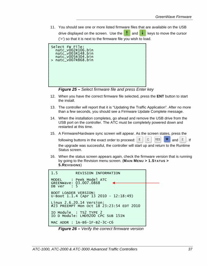
GreenWave Firmware
ATC-1000, ATC-2000 & ATC-3000 Advanced Traffic Controllers 37
11. You should see one or more listed firmware files that are available on the USB
drive displayed on the screen. Use the and keys to move the cursor (‘>’) so that it is next to the firmware file you wish to load.
Select FW File: natc_v002R106.bin natc_v003R148.bin natc_v005R304.bin > natc_v007R868.bin
Figure 25 – Select firmware file and press Enter key 12. When you have the correct firmware file selected, press the ENT button to start
the install.
13. The controller will report that it is “Updating the Traffic Application”. After no more than a few seconds, you should see a Firmware Update Complete message.
14. When the installation completes, go ahead and remove the USB drive from the USB port on the controller. The ATC must be completely powered down and restarted at this time.
15. A Firmware/Hardware sync screen will appear. As the screen states, press the
following buttons in the exact order to proceed: and . If the upgrade was successful, the controller will start up and return to the Runtime Status screen.
16. When the status screen appears again, check the firmware version that is running by going to the Revision menu screen. (MAIN MENU > 1.STATUS > 5.REVISIONS)
1.5 REVISION INFORMATION MODEL : Peek Model ATC GREENWave: 03.007.0868 DB ver : 5 BOOT LOADER VERSION: U-Boot 1.1.4 (Apr 13 2010 - 12:18:49) Linux 2.6.20.14 Version: #23 PREEMPT Mon Oct 18 23:23:54 EDT 2010 IO Module : TS2 TYPE 2 IO D Module: LMD9200 CPC SUB 15IN MAC ADDR : 1A-B6-1F-B2-3C-C6
Figure 26 – Verify the correct firmware version
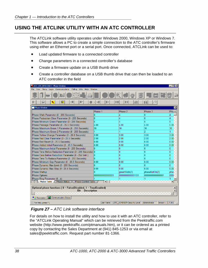
Chapter 1 — Introduction to the ATC Controllers
38 ATC-1000, ATC-2000 & ATC-3000 Advanced Traffic Controllers
USING THE ATCLINK UTILITY WITH AN ATC CONTROLLER
The ATCLink software utility operates under Windows 2000, Windows XP or Windows 7. This software allows a PC to create a simple connection to the ATC controller’s firmware using either an Ethernet port or a serial port. Once connected, ATCLink can be used to:
Load updated firmware to a connected controller
Change parameters in a connected controller’s database
Create a firmware update on a USB thumb drive
Create a controller database on a USB thumb drive that can then be loaded to an ATC controller in the field
Figure 27 – ATC Link software interface
For details on how to install the utility and how to use it with an ATC controller, refer to the “ATCLink Operating Manual” which can be retrieved from the Peektraffic.com website (http://www.peektraffic.com/ptmanuals.htm), or it can be ordered as a printed copy by contacting the Sales Department at (941) 845-1253 or via email at [email protected]. Request part number 81-1366.
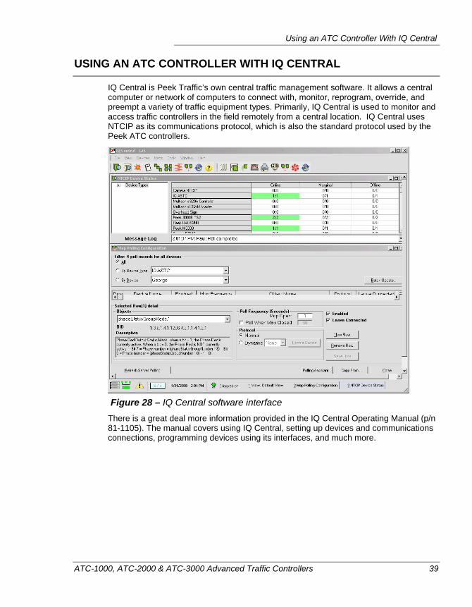
Using an ATC Controller With IQ Central
ATC-1000, ATC-2000 & ATC-3000 Advanced Traffic Controllers 39
USING AN ATC CONTROLLER WITH IQ CENTRAL
IQ Central is Peek Traffic’s own central traffic management software. It allows a central computer or network of computers to connect with, monitor, reprogram, override, and preempt a variety of traffic equipment types. Primarily, IQ Central is used to monitor and access traffic controllers in the field remotely from a central location. IQ Central uses NTCIP as its communications protocol, which is also the standard protocol used by the Peek ATC controllers.
Figure 28 – IQ Central software interface
There is a great deal more information provided in the IQ Central Operating Manual (p/n 81-1105). The manual covers using IQ Central, setting up devices and communications connections, programming devices using its interfaces, and much more.
Chapter 1 — Introduction to the ATC Controllers
40 ATC-1000, ATC-2000 & ATC-3000 Advanced Traffic Controllers
ATC-1000, ATC-2000 & ATC-3000 Advanced Traffic Controllers 41
Chapter 2 — Quick Start: Getting an ATC Up and Running
This chapter discusses how to get a new ATC controller operating and describes the basics of installing the unit in an intersection cabinet. The following topics are discussed in detail in this chapter:
• Hardware component checklist, on page 42.
• Software/firmware configuration checklist, on page 43.
• Setting Local Ethernet parameters, on page 43.
• Loading a default database, on page 45.
• An overview of controller field deployment, on page 46.
• The basics of programming a simple intersection, on page 47.
Chapter 2 — Quick Start: Getting an ATC Up and Running
42 ATC-1000, ATC-2000 & ATC-3000 Advanced Traffic Controllers
OVERVIEW
When an ATC controller is first sent to a customer, it will have firmware, a MAC address, an IP address, and a cabinet address pre-installed. These instructions explain how to take the factory-configured unit and prepare it for installation within a traffic cabinet
HARDWARE SETUP CHECKLIST
To operate properly, an ATC controller must be installed in a traffic cabinet environment that matches the type of hardware and firmware that is installed in the unit. However, before it can be inserted into a cabinet, you should verify that you have the following hardware elements for the controller:
ATC controller unit
The proper I/O module and D module to match your cabinet hardware (TS2 Type 1, TS2 Type 2, HMC-1000, or LMD 40)
A set of cabinet connectors that match the I/O module connectors. In particular, the power supplied on the pins of the ‘A’ connector must be valid for the I/O module.
Communications hardware to connect the controller to a central system, if one will be connected. This could include serial cables, Ethernet cabling to the cabinet, or an external modem and cables.
A USB data thumb drive for transporting controller firmware and databases to the controller in the field.†
Cabling to connect a conflict monitor or malfunction management unit (MMU)‡
Cabling for the data connection of an uninterruptable power supply (UPS) system*
Data key for transferring controller databases or conflict monitor compatibility matrices.§
Serial cable to connect an ATC Link PC to the controller via Port 5, or CAT5 cable to connect to the Ethernet port.
Properly jumpered programming card for the conflict monitor or MMU.**
† Optional items. Not strictly required for operation ‡ Only required in a NEMA cabinet § Alternately, this function can be performed using a laptop PC running the ATC Link utility ** Only required in a NEMA cabinet
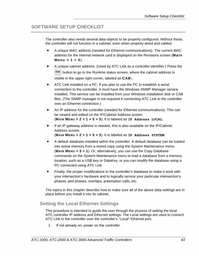
Software Setup Checklist
ATC-1000, ATC-2000 & ATC-3000 Advanced Traffic Controllers 43
SOFTWARE SETUP CHECKLIST
The controller also needs several data objects to be properly configured. Without these, the controller will not function in a cabinet, even when properly wired and cabled.
A unique MAC address (needed for Ethernet communications). The current MAC address for the internal network card is displayed on the Revisions screen (Main Menu > 1 > 5 ).
A unique cabinet address. (Used by ATC Link as a controller identifier.) Press the
button to go to the Runtime status screen, where the cabinet address is visible in the upper right corner, labeled as CAB: .
ATC Link installed on a PC. If you plan to use the PC to establish a serial connection to the controller, it must have the Windows SNMP Manager service installed. This service can be installed from your Windows installation disk or CAB files. (The SNMP manager is not required if connecting ATC Link to the controller over an Ethernet connection.)
An IP address for the controller (needed for Ethernet communications). This can be viewed and edited on the IP/Cabinet Address screen. (MAIN MENU > 2 > 1 > 5 > 3). It is labeled as IP Address LOCAL.
If an IP gateway address is needed, this is also available on the IP/Cabinet Address screen. (MAIN MENU > 2 > 1 > 5 > 3). It is labeled as IP Address SYSTEM.
A default database installed within the controller. A default database can be loaded into active memory from a stored copy using the System Maintenance menu. (MAIN MENU > 3 > 1). Or, alternatively, you can use the Copy Database commands on the System Maintenance menu to load a database from a memory location, such as a USB key or DataKey, or you can modify the database using a PC connected using ATC Link.
Finally, the proper modifications to the controller’s database to make it work with your intersection’s hardware and to logically service your particular intersection’s phases, ped phases, overlaps, preemption calls, etc.
The topics in this chapter describe how to make sure all of the above data settings are in place before you install it into its cabinet.
Setting the Local Ethernet Settings This procedure is intended to guide the user through the process of setting the local ATC controller IP address and Ethernet settings. The Local settings are used to connect ATC Link to the controller over the controller’s “Local” Ethernet port.
1. If not already on, power on the controller.
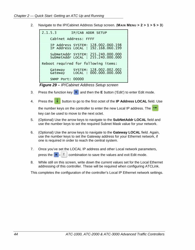
Chapter 2 — Quick Start: Getting an ATC Up and Running
44 ATC-1000, ATC-2000 & ATC-3000 Advanced Traffic Controllers
2. Navigate to the IP/Cabinet Address Setup screen. (MAIN MENU > 2 > 1 > 5 > 3)
2.1.5.3 IP/CAB ADDR SETUP Cabinet Address: FFFF IP Address SYSTEM: 128.002.060.198 IP Address LOCAL : 192.168.060.199 SubNetAddr SYSTEM: 255.240.000.000 SubNetAddr LOCAL : 255.240.000.000 Reboot required for following items: Gateway SYSTEM: 128.002.002.002 Gateway LOCAL : 000.000.000.000 SNMP Port: 00000
Figure 29 – IP/Cabinet Address Setup screen
3. Press the function key and then the E button (‘Edit’) to enter Edit mode.
4. Press the button to go to the first octet of the IP Address LOCAL field. Use
the number keys on the controller to enter the new Local IP address. The key can be used to move to the next octet.
5. (Optional) Use the arrow keys to navigate to the SubNetAddr LOCAL field and use the number keys to set the required Subnet Mask value for your network.
6. (Optional) Use the arrow keys to navigate to the Gateway LOCAL field. Again, use the number keys to set the Gateway address for your Ethernet network, if one is required in order to reach the central system.
7. Once you’ve set the LOCAL IP address and other Local network parameters, press the - combination to save the values and exit Edit mode.
8. While still on this screen, write down the current values set for the Local Ethernet addressing of this controller. These will be required when configuring ATCLink.
This completes the configuration of the controller’s Local IP Ethernet network settings.
Software Setup Checklist
ATC-1000, ATC-2000 & ATC-3000 Advanced Traffic Controllers 45
Configuring ATCLink and the SNMP Manager The next step in getting the ATC controller running is to install ATCLink on a laptopt PC, and to make sure that the PC has the SNMP Management service activated. (The SNMP service is only required if you plan to connect to the controller via a serial cable.) To accomplish these steps, you will need to have Administrative access to the computer, and either the Windows installation CDs or the .cab files of the Windows installation.
The full instructions for installing and configuring ATCLink is available in the ATC Link Operating Manual, (p/n 81-1366), which is available on the peektraffic.com website.
Note ATCLink is not strictly required in order to set up and operate the ATC controllers. (Unlike the ATC-1000, ATC-2000 and ATC-3000, the ATC CBD controllers are not programmable from the front interface, so IQ Link is required for their setup.) In contrast, the ATC-1000, 2000 and 3000 can be programmed entirely from their front panel interface; however, programming and maintaining a network of ATC controllers can be done more easily and conveniently when used in conjunction with the ATCLink and IQ Central software tools.
Loading a Default Database Into the Controller The process of loading a default database into the ATC controller couldn’t be simpler. The controller stores default databases internally as a backup system. To load one of the two available default databases into the controller’s active memory, follow these steps.
1. If not already on, power up your controller.
2. Navigate to the System Maintenance menu, and then select Database Utilities (MAIN MENU > 3 > 1)
3. Select whether you would like to install a simple 8 phase, dual ring configuration (option 1), or an 8 phase, dual ring configuration with pre-programmed coordination and preemption (option 2). The controller will load the database from memory and transition over to the new operation automatically.
4. It is recommended that you perform a restart of the controller at this point, just in case any channel assignments have changed as a result of the change.
Chapter 2 — Quick Start: Getting an ATC Up and Running
46 ATC-1000, ATC-2000 & ATC-3000 Advanced Traffic Controllers
FIELD DEPLOYMENT
Because of the large number of I/O options, central comms options, and operating parameters of the ATC controllers, the exact method to install the controller into one of your field cabinets is highly dependent on your local procedures and technical requirements. The basic process to install the controller in the field follows these steps:
1. (Optional) Power up the unit in the office, connecting it to a PC running ATCLink and program the controller with the intersection-specific database settings it needs.
2. Or, alternatively, you could load the programming onto the controller by plugging in a USB thumbdrive containing the database and powering up the unit. Load the database using the USB menu, which will appear automatically.
3. Ensure that all circuit breakers in the cabinet power distribution panel are off. Ensure that the input power is connected to the cabinet power panel and the appropriate buss bar. The cabinet must be wired properly for the intersection.
4. Ensure that all Signal light connections and detector input connections are properly made in the cabinet, including any necessary pedestrian inputs.
5. Place the controller onto a shelf in the cabinet.
6. Plug in the cabinet connectors to the I/O module of the ATC controller. This could be from one to six cables, depending on the type of I/O module, optional D Module, and cabinet you are using.
7. If you are using a TS2 Type 1 I/O module, Connect the SDLC communication cable from the cabinet’s MMU panel to the controller’s Port 1 connector. Ensure that the connector clips on the communication cable properly latches on to the locking blocks. If the MMU has not already been set up for this installation, program or jumper the appropriate co-phases on the MMU’s programming card. Reinsert the programming card into the MMU.
8. Turn on all circuit breakers in the cabinet. For normal three-color operation, check that the SIGNAL AUTO/FLASH switch of the cabinet is in the AUTO position and that the SIGNAL ON/OFF switch is in the ON position.
9. Verify that the ATC powers on and shows all six front panel power LEDs glowing green. Verify that the power up sequence clears successfully and the unit immediately shows the 1.1.1 Runtime Status screen. Verify that the Heartbeat LED is flashing steadily at approximately 4 flashes per second.
10. Observe the operation of the intersection signals and detection inputs to verify that the intersection is operating as expected.
This completes the general field deployment process.
Programming a Basic Intersection
ATC-1000, ATC-2000 & ATC-3000 Advanced Traffic Controllers 47
PROGRAMMING A BASIC INTERSECTION
Because of the numerous operating modes and options on a modern ATC controller, the programming of the controller can be a complex process. These are the high level steps requiretd to set up the parameters to run a normal intersection. These parameters can be programmed into ATCLink or IQ Central without having the controller connected, then once the parameters are double checked and verified, these can be loaded to the controller either over a Central-Local connection (for IQ Central), or using a USB drive or serial connection transfer from ATCLink.
Or you can bypass all of that and simply program the controller from the front panel using the keypad.
1. Load a Default Database that is similar to yours. (MAIN MENU > 3 > 1)
2. Define which phases are enabled. (Main Menu > 2 > 2 > 1)
3. Define how the controller should start up operating the intersection from a power off situation. (MAIN MENU > 2 > 1 > 1)
4. Setup the Flash mode you’d like to use for the intersection (MAIN MENU > 2 > 1 > 2)
5. Set the Green times for each phase (MAIN MENU > 2 > 2 > 2)
6. Set the Clearance times (Yellow and Red) for each phase (MAIN MENU > 2 > 2 > 3)
7. Set the Pedestrian times (Walk and Ped Clearance) for each Ped phase (MAIN MENU > 2 > 2 > 4)
8. Set up the vehicle detectors and link them to phases (MAIN MENU > 2 > 5 > 1) and (Main Menu > 2 > 5 > 3).
9. Set up pedestrian detectors and link them to Ped phases (MAIN MENU > 2 > 5 > 5) This completes the basic timing settings for the controller, but we still need to define the pattern that will be run to use these timings.
10. Go to the Coordination menu, go into the Split Table and fill in values for Split Table 1. (Main Menu > 2 >3 > 3, Table #1) For each phase you enabled in step 2 above, you will need to specify a Split time.
11. Back in the Coordination menu, go into the Pattern table, and make sure that Pattern 1 calls Split No 1. On this same screen, also under Pattern 1, define the total Cycle time for the intersection. (Main Menu > 2 > 3 > 2, Page 1, Pattern 1)
12. Now, go into the Time of Day menu and select Actions > Plans. (Main Menu > 2 > 4 > 1 > 1) Under Actn 1, make sure the Pattern (PATT) is set to 1. (Pattern 1 is what you just defined in the previous step.)
13. Back in the Time of Day menu, select Day Plans. On the first screen (Day Plan 1), define one event (Event #1) to call Action 1. (Main Menu > 2 > 4 > 2 > 1, Event #1)
14. Again, back in the Time of Day menu, select Schedules. In the first screen (Entry 01), make sure Schedule Day Plan is set to 1. Then put X’s under every Month,
Chapter 2 — Quick Start: Getting an ATC Up and Running
48 ATC-1000, ATC-2000 & ATC-3000 Advanced Traffic Controllers
Day and Date on the screen. This tells the controller to use the pattern we’ve just finished defining at all times. (Main Menu > 2 > 4 > 3 > 1, Entry 01)
These are the basic settings for a phase-based intersection running a single pattern, as controlled by the Time of Day scheduler. You can verify that this pattern is, in fact,
running by going to the Runtime Status screen (press the button) and verify that the number 1 shows up next to TOD CMD in the bottom right corner of the status display.
There are a multitude of additional capabilities that can be configured using the rest of the ATC programming screens, or alternately, using ATCLink or IQ Central as a programming interface. These include multiple patterns, Day Plan schedules, special daily Actions, preemption runs, TSP timing plans, interval-based patterns, and a variety of special overlap and other intra-cycle timing options. I respectfully point you to the table of contents of this manual to get you started.
ATC-1000, ATC-2000 & ATC-3000 Advanced Traffic Controllers 49
Chapter 3 — Introduction to the Interface
This chapter describes the keypad and front panel display interfaces of the Peek ATC controllers. The following topics are discussed:
• An overview of the menu and status screen environment, on page 51.
• Navigating in the Menus, on page 51.
• Firmware flowchart, on page 52.
• Entering the Menu system, on page 52.
• The Main, Utilities, and USB Menu systems, on page 54.
Chapter 3 — Introduction to the Interface
50 ATC-1000, ATC-2000 & ATC-3000 Advanced Traffic Controllers
OVERVIEW
When an ATC controller running the GREENWave firmware is powered on, it will go through a startup sequence. After it displays its splash screen, showing the Peek Traffic logo and some information about the firmware, the display will show the standard Controller Runtime Status screen. From there, the controller’s menu system can be
accessed using the Main Menu button ( ).
Help information is available throughout the interface by pressing the key.
Status screens cannot be edited.
For more details about how to navigate around in the menu system, see the next topic.

Navigating in the Environment
ATC-1000, ATC-2000 & ATC-3000 Advanced Traffic Controllers 51
NAVIGATING IN THE ENVIRONMENT
To navigate around in an ATC controller’s menu system requires an understanding of a few simple rules on how the menus and status screens work. These are the rules:
To switch from the Controller Status screen to the Main Menu, just press the MAIN
MENU button. ( )
To switch to the Main Menu from anywhere in the menu system, press the MAIN
MENU button. ( )
To go from any menu back to the Controller status screen, just press the HME key
( ).
To select an item on a menu, press the keypad number corresponding to that item.
To move upward in the menus structure, press the PREVIOUS button. ( )
After the firmware starts up, the data screens (also known as parameter screens) start out in read-only mode. The entire interface toggles between Read-Only and
Edit modes using the - key combination. (So if a user enters Edit mode on
one screen, returns to the menus, and goes into another parameter screen, the interface will still be in Edit mode.) Just be aware that changes to the values are not stored to the permanent database until one returns to Read-Only mode, so it is a good idea to enter and exit from Edit mode on each Data screen.
Note In some cases, errors can be reported on one screen due to parameter values stored on another screen. In such a case, it simply isn’t possible to save the values on each screen. Keep in mind that it is possible to navigate between screens without exiting from Edit mode. All of the changes will be saved at the same time whenever you do exit from Edit.
When working in parameter screens that have multiple pages, use the PAGE UP
and PAGE DOWN keys ( ) to switch between pages. Use the PREV key
( ) to exit from parameter screens back to the menus. The key will also
return you to the menus, but it will take you straight to the Main Menu. Some parameter screens have two dimensions of screens (for example, the TSP Run Configuration Screens: Configurations 1 through 8, and Runs 1 through 8.) The first dimension is selected using Page Up and Page Down, the second dimension is selected using the numbered keys on the keypad.
Help Topics – The key is used to see the help screens for whatever menu,
status screen or data screen that is currently showing on the display. Help topics
that have multiple pages of information can be navigated using the and
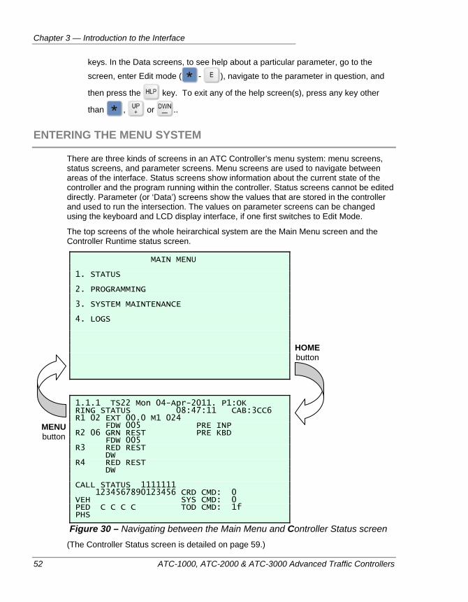
Chapter 3 — Introduction to the Interface
52 ATC-1000, ATC-2000 & ATC-3000 Advanced Traffic Controllers
keys. In the Data screens, to see help about a particular parameter, go to the
screen, enter Edit mode ( - ), navigate to the parameter in question, and
then press the key. To exit any of the help screen(s), press any key other
than , or ..
ENTERING THE MENU SYSTEM
There are three kinds of screens in an ATC Controller’s menu system: menu screens, status screens, and parameter screens. Menu screens are used to navigate between areas of the interface. Status screens show information about the current state of the controller and the program running within the controller. Status screens cannot be edited directly. Parameter (or ‘Data’) screens show the values that are stored in the controller and used to run the intersection. The values on parameter screens can be changed using the keyboard and LCD display interface, if one first switches to Edit Mode.
The top screens of the whole heirarchical system are the Main Menu screen and the Controller Runtime status screen.
MAIN MENU 1. STATUS 2. PROGRAMMING 3. SYSTEM MAINTENANCE 4. LOGS
1.1.1 TS22 Mon 04-Apr-2011. P1:OK RING STATUS 08:47:11 CAB:3CC6 R1 02 EXT 00.0 M1 024 FDW 005 PRE INP R2 06 GRN REST PRE KBD FDW 005 R3 RED REST DW R4 RED REST DW CALL STATUS 1111111 1234567890123456 CRD CMD: 0 VEH SYS CMD: 0 PED C C C C TOD CMD: 1f PHS
Figure 30 – Navigating between the Main Menu and Controller Status screen (The Controller Status screen is detailed on page 59.)
MENU button
HOME button
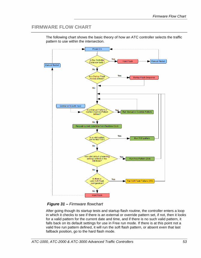
Firmware Flow Chart
ATC-1000, ATC-2000 & ATC-3000 Advanced Traffic Controllers 53
FIRMWARE FLOW CHART
The following chart shows the basic theory of how an ATC controller selects the traffic pattern to use within the intersection.
Figure 31 – Firmware flowchart
After going though its startup tests and startup flash routine, the controller enters a loop in which it checks to see if there is an external or override pattern set, if not, then it looks for a valid pattern for the current date and time, and if there is no such valid pattern, it falls back on its default settings for use in Free run mode. If there is at this point not a valid free run pattern defined, it will run the soft flash pattern, or absent even that last fallback position, go to the hard flash mode.
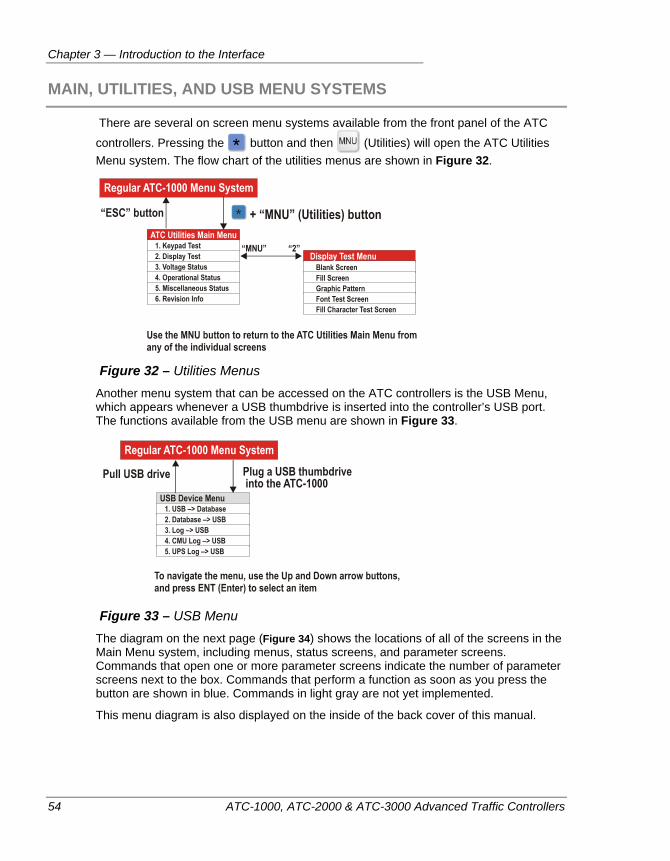
Chapter 3 — Introduction to the Interface
54 ATC-1000, ATC-2000 & ATC-3000 Advanced Traffic Controllers
MAIN, UTILITIES, AND USB MENU SYSTEMS
There are several on screen menu systems available from the front panel of the ATC
controllers. Pressing the button and then (Utilities) will open the ATC Utilities Menu system. The flow chart of the utilities menus are shown in Figure 32.
Figure 32 – Utilities Menus
Another menu system that can be accessed on the ATC controllers is the USB Menu, which appears whenever a USB thumbdrive is inserted into the controller’s USB port. The functions available from the USB menu are shown in Figure 33.
Figure 33 – USB Menu
The diagram on the next page (Figure 34) shows the locations of all of the screens in the Main Menu system, including menus, status screens, and parameter screens. Commands that open one or more parameter screens indicate the number of parameter screens next to the box. Commands that perform a function as soon as you press the button are shown in blue. Commands in light gray are not yet implemented.
This menu diagram is also displayed on the inside of the back cover of this manual.
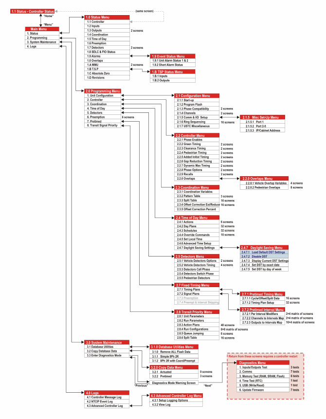
Main, Utilities, and USB Menu Systems
ATC-1000, ATC-2000 & ATC-3000 Advanced Traffic Controllers 55
Figure 34 – Top-down view of the ATC-1000 Menu System
Chapter 3 — Introduction to the Interface
56 ATC-1000, ATC-2000 & ATC-3000 Advanced Traffic Controllers
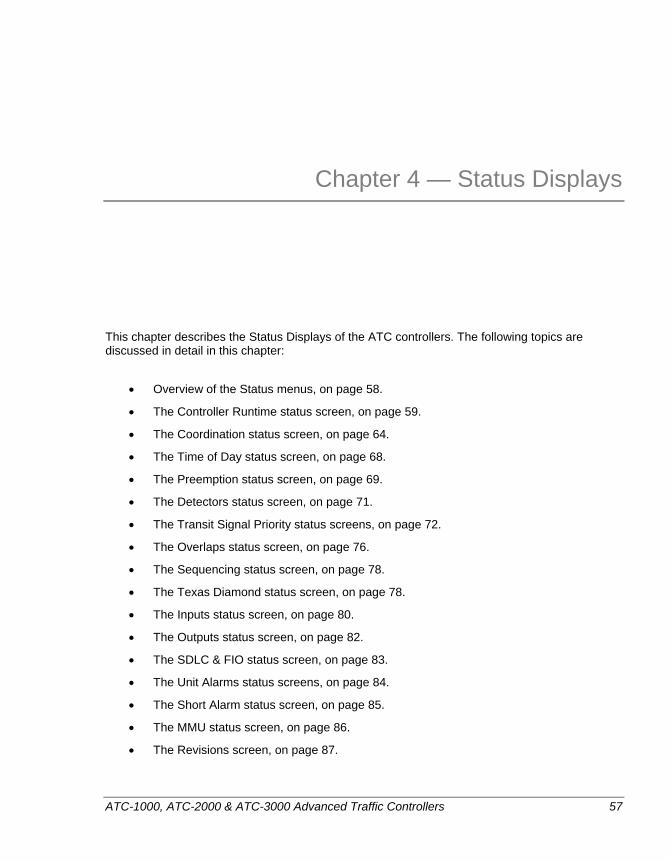
ATC-1000, ATC-2000 & ATC-3000 Advanced Traffic Controllers 57
Chapter 4 — Status Displays
This chapter describes the Status Displays of the ATC controllers. The following topics are discussed in detail in this chapter:
• Overview of the Status menus, on page 58.
• The Controller Runtime status screen, on page 59.
• The Coordination status screen, on page 64.
• The Time of Day status screen, on page 68.
• The Preemption status screen, on page 69.
• The Detectors status screen, on page 71.
• The Transit Signal Priority status screens, on page 72.
• The Overlaps status screen, on page 76.
• The Sequencing status screen, on page 78.
• The Texas Diamond status screen, on page 78.
• The Inputs status screen, on page 80.
• The Outputs status screen, on page 82.
• The SDLC & FIO status screen, on page 83.
• The Unit Alarms status screens, on page 84.
• The Short Alarm status screen, on page 85.
• The MMU status screen, on page 86.
• The Revisions screen, on page 87.
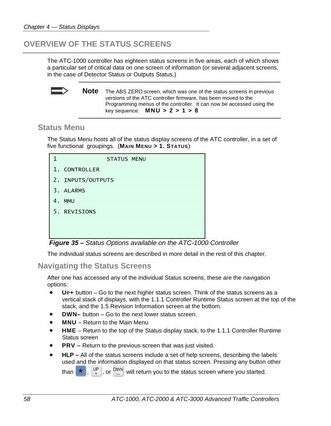
Chapter 4 — Status Displays
58 ATC-1000, ATC-2000 & ATC-3000 Advanced Traffic Controllers
OVERVIEW OF THE STATUS SCREENS
The ATC-1000 controller has eighteen status screens in five areas, each of which shows a particular set of critical data on one screen of information (or several adjacent screens, in the case of Detector Status or Outputs Status.)
Note The ABS ZERO screen, which was one of the status screens in previous versions of the ATC controller firmware, has been moved to the Programming menus of the controller. It can now be accessed using the key sequence: MNU > 2 > 1 > 8
Status Menu The Status Menu hosts all of the status display screens of the ATC controller, in a set of five functional groupings. (MAIN MENU > 1. STATUS)
1 STATUS MENU 1. CONTROLLER 2. INPUTS/OUTPUTS 3. ALARMS 4. MMU 5. REVISIONS
Figure 35 – Status Options available on the ATC-1000 Controller The individual status screens are described in more detail in the rest of this chapter.
Navigating the Status Screens After one has accessed any of the individual Status screens, these are the navigation options: UP+ button – Go to the next higher status screen. Think of the status screens as a
vertical stack of displays, with the 1.1.1 Controller Runtime Status screen at the top of the stack, and the 1.5 Revision Information screen at the bottom.
DWN– button – Go to the next lower status screen. MNU – Return to the Main Menu HME – Return to the top of the Status display stack, to the 1.1.1 Controller Runtime
Status screen PRV – Return to the previous screen that was just visited. HLP – All of the status screens include a set of help screens, describing the labels
used and the information displayed on that status screen. Pressing any button other
than , , or will return you to the status screen where you started.
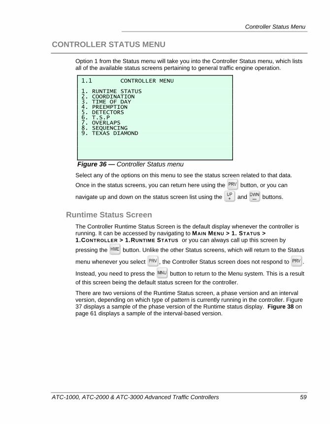
Controller Status Menu
ATC-1000, ATC-2000 & ATC-3000 Advanced Traffic Controllers 59
CONTROLLER STATUS MENU
Option 1 from the Status menu will take you into the Controller Status menu, which lists all of the available status screens pertaining to general traffic engine operation.
1.1 CONTROLLER MENU 1. RUNTIME STATUS 2. COORDINATION 3. TIME OF DAY 4. PREEMPTION 5. DETECTORS 6. T.S.P 7. OVERLAPS 8. SEQUENCING 9. TEXAS DIAMOND
Figure 36 — Controller Status menu Select any of the options on this menu to see the status screen related to that data.
Once in the status screens, you can return here using the button, or you can
navigate up and down on the status screen list using the and buttons.
Runtime Status Screen The Controller Runtime Status Screen is the default display whenever the controller is running. It can be accessed by navigating to MAIN MENU > 1. STATUS > 1.CONTROLLER > 1.RUNTIME STATUS or you can always call up this screen by
pressing the button. Unlike the other Status screens, which will return to the Status
menu whenever you select , the Controller Status screen does not respond to .
Instead, you need to press the button to return to the Menu system. This is a result of this screen being the default status screen for the controller.
There are two versions of the Runtime Status screen, a phase version and an interval version, depending on which type of pattern is currently running in the controller. Figure 37 displays a sample of the phase version of the Runtime status display. Figure 38 on page 61 displays a sample of the interval-based version.
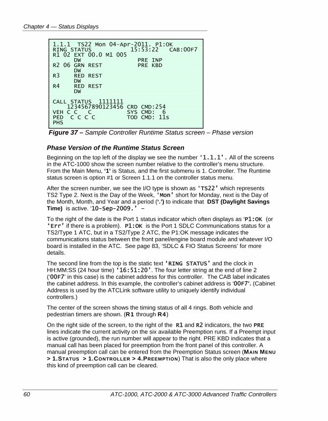
Chapter 4 — Status Displays
60 ATC-1000, ATC-2000 & ATC-3000 Advanced Traffic Controllers
1.1.1 TS22 Mon 04-Apr-2011. P1:OK RING STATUS 15:53:22 CAB:00F7 R1 02 EXT 00.0 M1 005 DW PRE INP R2 06 GRN REST PRE KBD DW R3 RED REST DW R4 RED REST DW CALL STATUS 1111111 1234567890123456 CRD CMD:254 VEH C C C SYS CMD: 6 PED C C C C TOD CMD: 11s PHS
Figure 37 – Sample Controller Runtime Status screen – Phase version
Phase Version of the Runtime Status Screen Beginning on the top left of the display we see the number ‘1.1.1’. All of the screens in the ATC-1000 show the screen number relative to the controller’s menu structure. From the Main Menu, ‘1’ is Status, and the first submenu is 1. Controller. The Runtime status screen is option #1 or Screen 1.1.1 on the controller status menu.
After the screen number, we see the I/O type is shown as ‘TS22’ which represents TS2 Type 2. Next is the Day of the Week, ‘Mon’ short for Monday, next is the Day of the Month, Month, and Year and a period (‘.’) to indicate that DST (Daylight Savings Time) is active. ‘10-Sep-2009.’ –
To the right of the date is the Port 1 status indicator which often displays as ‘P1:OK (or ‘Err’ if there is a problem). P1:OK is the Port 1 SDLC Communications status for a TS2/Type 1 ATC, but in a TS2/Type 2 ATC, the P1:OK message indicates the communications status between the front panel/engine board module and whatever I/O board is installed in the ATC. See page 83, ‘SDLC & FIO Status Screens’ for more details.
The second line from the top is the static text ‘RING STATUS’ and the clock in HH:MM:SS (24 hour time) ‘16:51:20’. The four letter string at the end of line 2 (‘00F7’ in this case) is the cabinet address for this controller. The CAB label indicates the cabinet address. In this example, the controller’s cabinet address is ‘00F7’. (Cabinet Address is used by the ATCLink software utility to uniquely identify individual controllers.)
The center of the screen shows the timing status of all 4 rings. Both vehicle and pedestrian timers are shown. (R1 through R4 )
On the right side of the screen, to the right of the R1 and R2 indicators, the two PRE lines indicate the current activity on the six available Preemption runs. If a Preempt input is active (grounded), the run number will appear to the right. PRE KBD indicates that a manual call has been placed for preemption from the front panel of this controller. A manual preemption call can be entered from the Preemption Status screen (MAIN MENU > 1.STATUS > 1.CONTROLLER > 4.PREEMPTION) That is also the only place where this kind of preemption call can be cleared.
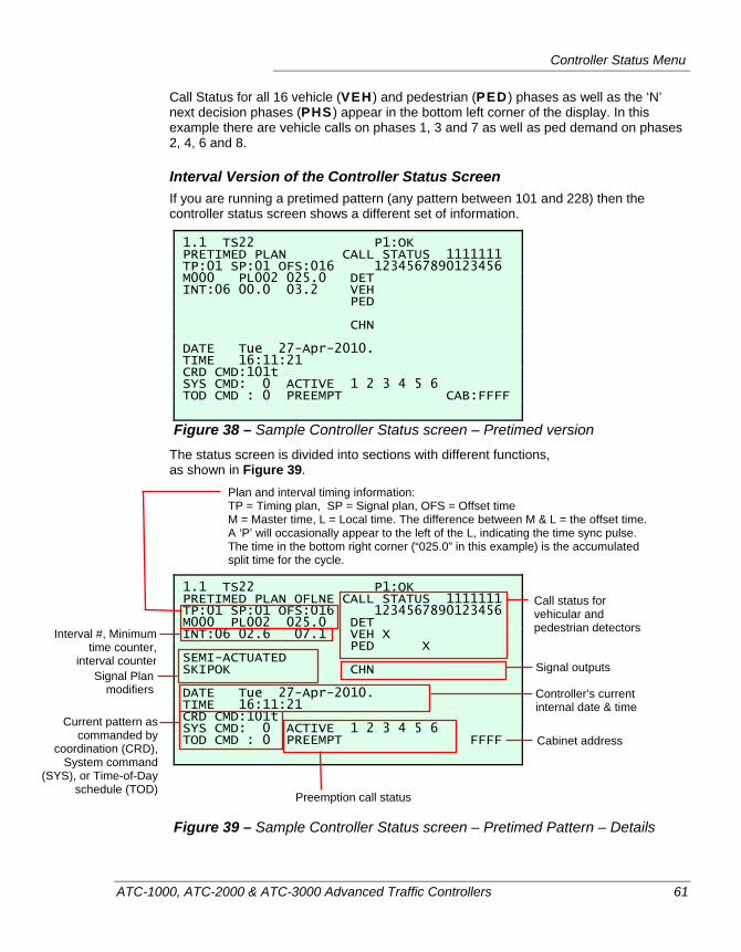
Controller Status Menu
ATC-1000, ATC-2000 & ATC-3000 Advanced Traffic Controllers 61
Call Status for all 16 vehicle (VEH ) and pedestrian (PED ) phases as well as the ‘N’ next decision phases (PHS ) appear in the bottom left corner of the display. In this example there are vehicle calls on phases 1, 3 and 7 as well as ped demand on phases 2, 4, 6 and 8.
Interval Version of the Controller Status Screen If you are running a pretimed pattern (any pattern between 101 and 228) then the controller status screen shows a different set of information.
1.1 TS22 P1:OK PRETIMED PLAN CALL STATUS 1111111 TP:01 SP:01 OFS:016 1234567890123456 M000 PL002 025.0 DET INT:06 00.0 03.2 VEH PED CHN DATE Tue 27-Apr-2010. TIME 16:11:21 CRD CMD:101t SYS CMD: 0 ACTIVE 1 2 3 4 5 6 TOD CMD : 0 PREEMPT CAB:FFFF
Figure 38 – Sample Controller Status screen – Pretimed version The status screen is divided into sections with different functions, as shown in Figure 39.
1.1 TS22 P1:OK PRETIMED PLAN OFLNE CALL STATUS 1111111 TP:01 SP:01 OFS:016 1234567890123456 M000 PL002 025.0 DET INT:06 02.6 07.1 VEH X PED X SEMI-ACTUATED SKIPOK CHN DATE Tue 27-Apr-2010. TIME 16:11:21 CRD CMD:101t SYS CMD: 0 ACTIVE 1 2 3 4 5 6 TOD CMD : 0 PREEMPT FFFF
Figure 39 – Sample Controller Status screen – Pretimed Pattern – Details
Call status for vehicular and pedestrian detectors
Controller’s current internal date & time
Preemption call status
Current pattern as commanded by
coordination (CRD), System command
(SYS), or Time-of-Day schedule (TOD)
Cabinet address
Plan and interval timing information: TP = Timing plan, SP = Signal plan, OFS = Offset time M = Master time, L = Local time. The difference between M & L = the offset time. A ‘P’ will occasionally appear to the left of the L, indicating the time sync pulse. The time in the bottom right corner (“025.0” in this example) is the accumulated split time for the cycle.
Signal Plan modifiers
Interval #, Minimum time counter,
interval counter Signal outputs
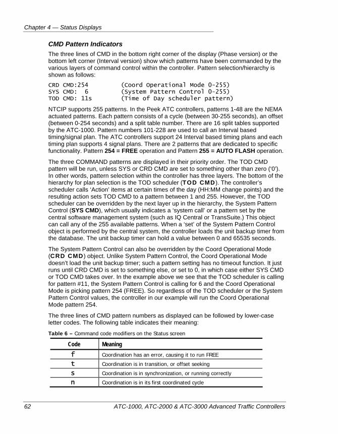
Chapter 4 — Status Displays
62 ATC-1000, ATC-2000 & ATC-3000 Advanced Traffic Controllers
CMD Pattern Indicators The three lines of CMD in the bottom right corner of the display (Phase version) or the bottom left corner (Interval version) show which patterns have been commanded by the various layers of command control within the controller. Pattern selection/hierarchy is shown as follows:
CRD CMD:254 (Coord Operational Mode 0-255) SYS CMD: 6 (System Pattern Control 0-255) TOD CMD: 11s (Time of Day scheduler pattern)
NTCIP supports 255 patterns. In the Peek ATC controllers, patterns 1-48 are the NEMA actuated patterns. Each pattern consists of a cycle (between 30-255 seconds), an offset (between 0-254 seconds) and a split table number. There are 16 split tables supported by the ATC-1000. Pattern numbers 101-228 are used to call an Interval based timing/signal plan. The ATC controllers support 24 Interval based timing plans and each timing plan supports 4 signal plans. There are 2 patterns that are dedicated to specific functionality. Pattern 254 = FREE operation and Pattern 255 = AUTO FLASH operation.
The three COMMAND patterns are displayed in their priority order. The TOD CMD pattern will be run, unless SYS or CRD CMD are set to something other than zero (‘0’). In other words, pattern selection within the controller has three layers. The bottom of the hierarchy for plan selection is the TOD scheduler (TOD CMD ). The controller’s scheduler calls ‘Action’ items at certain times of the day (HH:MM change points) and the resulting action sets TOD CMD to a pattern between 1 and 255. However, the TOD scheduler can be overridden by the next layer up in the hierarchy, the System Pattern Control (SYS CMD), which usually indicates a ‘system call’ or a pattern set by the central software management system (such as IQ Central or TransSuite.) This object can call any of the 255 available patterns. When a ‘set’ of the System Pattern Control object is performed by the central system, the controller loads the unit backup timer from the database. The unit backup timer can hold a value between 0 and 65535 seconds.
The System Pattern Control can also be overridden by the Coord Operational Mode (CRD CMD ) object. Unlike System Pattern Control, the Coord Operational Mode doesn’t load the unit backup timer; such a pattern setting has no timeout function. It just runs until CRD CMD is set to something else, or set to 0, in which case either SYS CMD or TOD CMD takes over. In the example above we see that the TOD scheduler is calling for pattern #11, the System Pattern Control is calling for 6 and the Coord Operational Mode is picking pattern 254 (FREE). So regardless of the TOD scheduler or the System Pattern Control values, the controller in our example will run the Coord Operational Mode pattern 254.
The three lines of CMD pattern numbers as displayed can be followed by lower-case letter codes. The following table indicates their meaning:
Table 6 – Command code modifiers on the Status screen
Code Meaning f Coordination has an error, causing it to run FREE
t Coordination is in transition, or offset seeking
s Coordination is in synchronization, or running correctly
n Coordination is in its first coordinated cycle
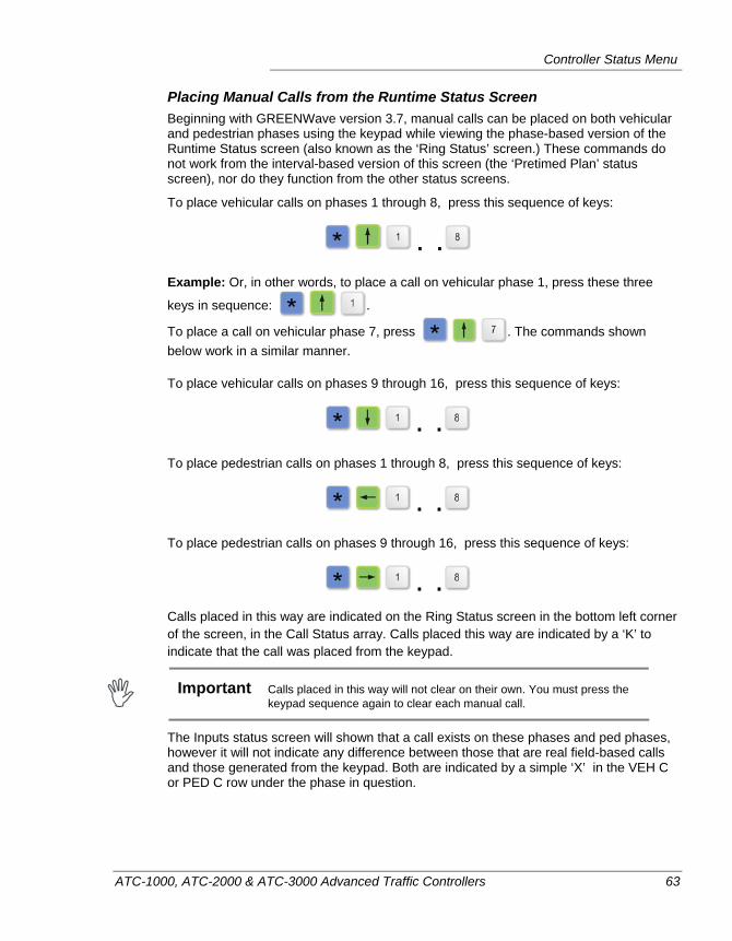
Controller Status Menu
ATC-1000, ATC-2000 & ATC-3000 Advanced Traffic Controllers 63
Placing Manual Calls from the Runtime Status Screen Beginning with GREENWave version 3.7, manual calls can be placed on both vehicular and pedestrian phases using the keypad while viewing the phase-based version of the Runtime Status screen (also known as the ‘Ring Status’ screen.) These commands do not work from the interval-based version of this screen (the ‘Pretimed Plan’ status screen), nor do they function from the other status screens.
To place vehicular calls on phases 1 through 8, press this sequence of keys:
. . Example: Or, in other words, to place a call on vehicular phase 1, press these three
keys in sequence: .
To place a call on vehicular phase 7, press . The commands shown below work in a similar manner.
To place vehicular calls on phases 9 through 16, press this sequence of keys:
. . To place pedestrian calls on phases 1 through 8, press this sequence of keys:
. . To place pedestrian calls on phases 9 through 16, press this sequence of keys:
. . Calls placed in this way are indicated on the Ring Status screen in the bottom left corner of the screen, in the Call Status array. Calls placed this way are indicated by a ‘K’ to indicate that the call was placed from the keypad.
Important Calls placed in this way will not clear on their own. You must press the
keypad sequence again to clear each manual call.
The Inputs status screen will shown that a call exists on these phases and ped phases, however it will not indicate any difference between those that are real field-based calls and those generated from the keypad. Both are indicated by a simple ‘X’ in the VEH C or PED C row under the phase in question.
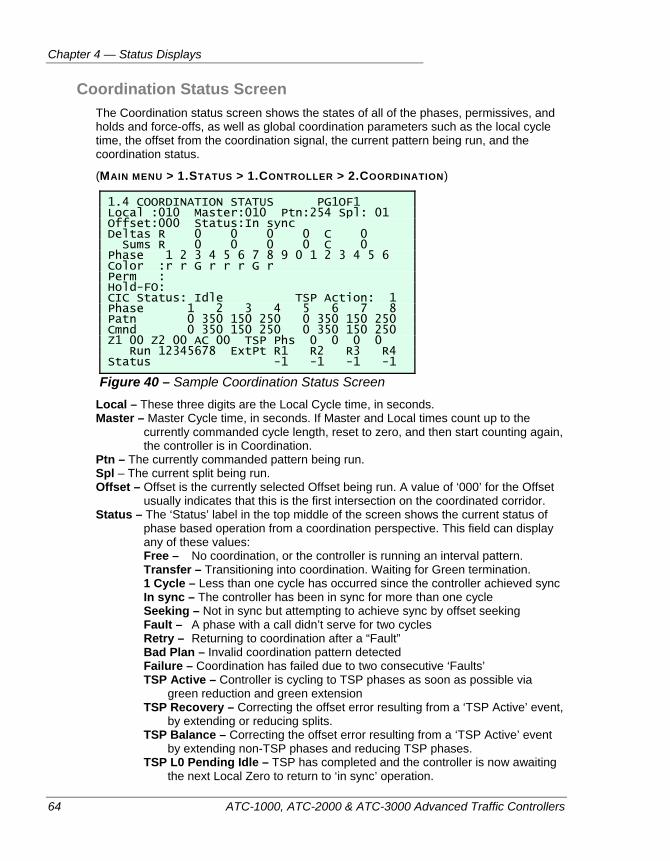
Chapter 4 — Status Displays
64 ATC-1000, ATC-2000 & ATC-3000 Advanced Traffic Controllers
Coordination Status Screen The Coordination status screen shows the states of all of the phases, permissives, and holds and force-offs, as well as global coordination parameters such as the local cycle time, the offset from the coordination signal, the current pattern being run, and the coordination status.
(MAIN MENU > 1.STATUS > 1.CONTROLLER > 2.COORDINATION)
1.4 COORDINATION STATUS PG1OF1 Local :010 Master:010 Ptn:254 Spl: 01 Offset:000 Status:In sync Deltas R 0 0 0 0 C 0 Sums R 0 0 0 0 C 0 Phase 1 2 3 4 5 6 7 8 9 0 1 2 3 4 5 6 Color :r r G r r r G r Perm : Hold-FO: CIC Status: Idle TSP Action: 1 Phase 1 2 3 4 5 6 7 8 Patn 0 350 150 250 0 350 150 250 Cmnd 0 350 150 250 0 350 150 250 Z1 00 Z2 00 AC 00 TSP Phs 0 0 0 0 Run 12345678 ExtPt R1 R2 R3 R4 Status -1 -1 -1 -1
Figure 40 – Sample Coordination Status Screen Local – These three digits are the Local Cycle time, in seconds. Master – Master Cycle time, in seconds. If Master and Local times count up to the
currently commanded cycle length, reset to zero, and then start counting again, the controller is in Coordination.
Ptn – The currently commanded pattern being run. Spl – The current split being run. Offset – Offset is the currently selected Offset being run. A value of ‘000’ for the Offset
usually indicates that this is the first intersection on the coordinated corridor. Status – The ‘Status’ label in the top middle of the screen shows the current status of
phase based operation from a coordination perspective. This field can display any of these values: Free – No coordination, or the controller is running an interval pattern. Transfer – Transitioning into coordination. Waiting for Green termination. 1 Cycle – Less than one cycle has occurred since the controller achieved sync In sync – The controller has been in sync for more than one cycle Seeking – Not in sync but attempting to achieve sync by offset seeking Fault – A phase with a call didn’t serve for two cycles Retry – Returning to coordination after a “Fault” Bad Plan – Invalid coordination pattern detected Failure – Coordination has failed due to two consecutive ‘Faults’ TSP Active – Controller is cycling to TSP phases as soon as possible via
green reduction and green extension TSP Recovery – Correcting the offset error resulting from a ‘TSP Active’ event,
by extending or reducing splits. TSP Balance – Correcting the offset error resulting from a ‘TSP Active’ event
by extending non-TSP phases and reducing TSP phases. TSP L0 Pending Idle – TSP has completed and the controller is now awaiting
the next Local Zero to return to ‘in sync’ operation.
Controller Status Menu
ATC-1000, ATC-2000 & ATC-3000 Advanced Traffic Controllers 65
Deltas:Ring – The split deltas (time differences, in seconds) for Rings 1 through 4, projected for the current cycle, after the most recent split adjustment caused by TSP operation.
Deltas:Cyc – The cycle deltas (time differences, in seconds) for the current cycle, after the most recent TSP-caused split adjustment.
Sums:Ring/Cyc – These are the remaining time differences for Rings 1 through 4 and the current cycle. At the local Zero, the current Deltas are added to the sums, and the delta is set to zero.
Color – Current color shown by the phase. The possible values are: G=Green/Don’t Walk, W=Green/Walk, Y=Yellow, r=Red/Phase Off, R=Red clearance, P=Flashing Don’t Walk (Ped clearance)
Perm – Shows the current permissive status for each phase: V=Vehicle permitted/Peds not permitted, C=Coordinated phase , B=Both vehicles and peds permitted
Hold-FO – Shows whether a Hold or a Force-Off are currently active for this phase (H=Hold, F=Force-Off)
CIC Status – Critical Intersection Control operational status. The possible values are: Idle = ATC is running with no CIC cycle, offsets, splits (C/O/S) and no active CIC Set command from the Central System Pending = a CIC C/O/S and Set command has been accepted in the same Pattern Number currently running, the controller is now waiting for top of cycle Success = ATC is currently running a CIC-commanded C/O/S pattern and has no valid exit commands Error = ATC has rejected a CIC C/O/S command because the values violated one or more Coordination Consistency Checks
TSP Action – The current TSP Action plan number, as defined on controller screen 2.8.3. This defines how the controller will respond should it receive a TSP input call. (Refer to “TSP Action Plans” on page 270.)
Patn – Shows the split times, in tenths of seconds, for the current pattern Cmnd – Shows the split times, in tenths of seconds, for a CIC or TSP commanded pattern
Z1 – Priority Zone 1 called by TSP Inputs 1-8, displayed in hexadecimal
Z2 – Priority Zone 2 called by TSP Inputs 9-16, displayed in hexidecimal
AC – Advanced Cancel called by TSP Inputs 17-24, displayed in hexidecimal
TSP Phs – Phases receiving TSP activity
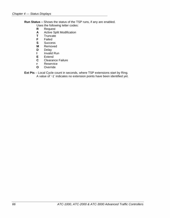
Chapter 4 — Status Displays
66 ATC-1000, ATC-2000 & ATC-3000 Advanced Traffic Controllers
Run Status – Shows the status of the TSP runs, if any are enabled. Uses the following letter codes: R Request A Active Split Modification T Truncate F Failed S Success M Removed D Delay I Invalid Run E Extend C Clearance Failure r Reservice O Override
Ext Pts – Local Cycle count in seconds, where TSP extensions start by Ring. A value of ‘-1’ indicates no extension points have been identified yet.
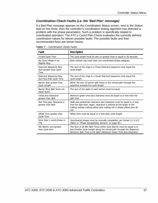
Controller Status Menu
ATC-1000, ATC-2000 & ATC-3000 Advanced Traffic Controllers 67
Coordination Check Faults (i.e. the ‘Bad Plan’ message) If a Bad Plan message appears on the Coordination Status screen, next to the Status field on line three, then the controller’s coordination testing algorithm has detected a problem with the phase parameters. Such a problem is specifically related to coordinated operation. The ATC’s Coord Plan Check evaluates the currently defined coordination values for eleven possible faults. The possible faults and their recommended fixes are shown below.
Table 7 – Coordination Check Faults
Fault Description Invalid Cycle Time The cycle length must be zero or greater than or equal to 30 seconds.
No Coord Phase in an Eligible Ring
Each utilized ring must have one coordinated phase assigned.
Diamond Sequence Ring Sum greater than Cycle Time
The sum of the rings in a Texas Diamond sequence must equal the cycle length.
Diamond Sequence Ring Sum less than Cycle Time
The sum of the rings in a Texas Diamond sequence must equal the cycle length.
Barrier Sum greater than Cycle Length
Either the sum of barrier split times or the critical path through the sequence exceeds the cycle length.
Barrier Ring Split Sums not equal Sums
The sum of the splits in each barrier must be equal.
Initial plus Clearance greater than Split
Minimum green time plus clearance must be equal to or less than the split time.
Ped Time plus Clearance is greater than Split
Walk plus pedestrian clearance plus clearance must be equal to or less than the split time. Again, clearance is defined as the larger of the trailing overlap trailing yellow plus trailing red or phase yellow plus all-red.
Offset Time greater than Cycle Time
Offset time must be equal to or less than cycle length.
More than 1 coord phase in ring
Coordinated phases must be mutually compatible, per Screen 2.1.3.1/2. (Refer to “Phase Compatibility Screens” on page 95.)
Min Barrier sum greater than cycle time
The Sum of all Min Split Times within each Barrier must be equal to or less thanthe Cycle Length along the critical path through the Sequence. Minimum Split Time is the Split’s Minimum Green Time plus Clearance.
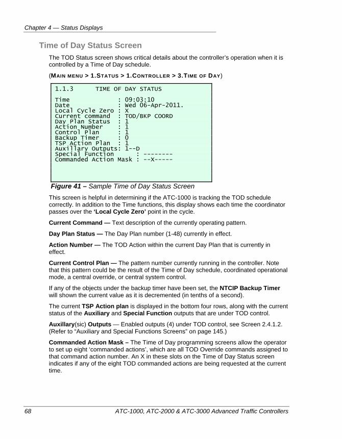
Chapter 4 — Status Displays
68 ATC-1000, ATC-2000 & ATC-3000 Advanced Traffic Controllers
Time of Day Status Screen The TOD Status screen shows critical details about the controller’s operation when it is controlled by a Time of Day schedule.
(MAIN MENU > 1.STATUS > 1.CONTROLLER > 3.TIME OF DAY)
1.1.3 TIME OF DAY STATUS Time : 09:03:10 Date : Wed 06-Apr-2011. Local Cycle Zero : X Current command : TOD/BKP COORD Day Plan Status : 1 Action Number : 1 Control Plan : 1 Backup Timer : 0 TSP Action Plan : 1 Auxillary Outputs: 1--D Special Function : -------- Commanded Action Mask : --X-----
Figure 41 – Sample Time of Day Status Screen This screen is helpful in determining if the ATC-1000 is tracking the TOD schedule correctly. In addition to the Time functions, this display shows each time the coordinator passes over the ‘Local Cycle Zero’ point in the cycle.
Current Command — Text description of the currently operating pattern.
Day Plan Status — The Day Plan number (1-48) currently in effect.
Action Number — The TOD Action within the current Day Plan that is currently in effect.
Current Control Plan — The pattern number currently running in the controller. Note that this pattern could be the result of the Time of Day schedule, coordinated operational mode, a central override, or central system control.
If any of the objects under the backup timer have been set, the NTCIP Backup Timer will shown the current value as it is decremented (in tenths of a second).
The current TSP Action plan is displayed in the bottom four rows, along with the current status of the Auxiliary and Special Function outputs that are under TOD control.
Auxillary(sic) Outputs — Enabled outputs (4) under TOD control, see Screen 2.4.1.2. (Refer to “Auxiliary and Special Functions Screens” on page 145.)
Commanded Action Mask – The Time of Day programming screens allow the operator to set up eight ‘commanded actions’, which are all TOD Override commands assigned to that command action number. An X in these slots on the Time of Day Status screen indicates if any of the eight TOD commanded actions are being requested at the current time.
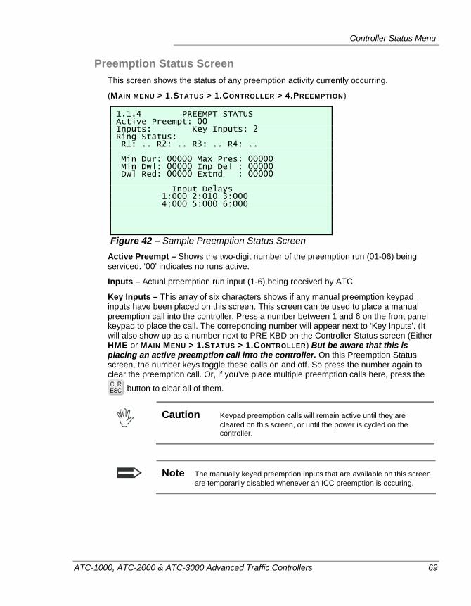
Controller Status Menu
ATC-1000, ATC-2000 & ATC-3000 Advanced Traffic Controllers 69
Preemption Status Screen This screen shows the status of any preemption activity currently occurring.
(MAIN MENU > 1.STATUS > 1.CONTROLLER > 4.PREEMPTION)
1.1.4 PREEMPT STATUS Active Preempt: 00 Inputs: Key Inputs: 2 Ring Status: R1: .. R2: .. R3: .. R4: .. Min Dur: 00000 Max Pres: 00000 Min Dwl: 00000 Inp Del : 00000 Dwl Red: 00000 Extnd : 00000 Input Delays 1:000 2:010 3:000 4:000 5:000 6:000
Figure 42 – Sample Preemption Status Screen Active Preempt – Shows the two-digit number of the preemption run (01-06) being serviced. ‘00’ indicates no runs active.
Inputs – Actual preemption run input (1-6) being received by ATC.
Key Inputs – This array of six characters shows if any manual preemption keypad inputs have been placed on this screen. This screen can be used to place a manual preemption call into the controller. Press a number between 1 and 6 on the front panel keypad to place the call. The correponding number will appear next to ‘Key Inputs’. (It will also show up as a number next to PRE KBD on the Controller Status screen (Either HME or MAIN MENU > 1.STATUS > 1.CONTROLLER) But be aware that this is placing an active preemption call into the controller. On this Preemption Status screen, the number keys toggle these calls on and off. So press the number again to clear the preemption call. Or, if you’ve place multiple preemption calls here, press the
button to clear all of them.
Caution Keypad preemption calls will remain active until they are
cleared on this screen, or until the power is cycled on the controller.
Note The manually keyed preemption inputs that are available on this screen are temporarily disabled whenever an ICC preemption is occuring.
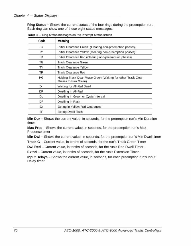
Chapter 4 — Status Displays
70 ATC-1000, ATC-2000 & ATC-3000 Advanced Traffic Controllers
Ring Status – Shows the current status of the four rings during the preemption run. Each ring can show one of these eight status messages:
Table 8 – Ring Status messages on the Preempt Status screen
Code Meaning IG Initial Clearance Green. (Clearing non-preemption phases)
IY Initial Clearance Yellow (Clearing non-preemption phases)
IR Initial Clearance Red (Clearing non-preemption phases)
TG Track Clearance Green
TY Track Clearance Yellow
TR Track Clearance Red
HG Holding Track Clear Phase Green (Waiting for other Track Clear Phases to turn Green)
DI Waiting for All-Red Dwell
DR Dwelling in All-Red
DL Dwelling in Green or Cyclic Interval
DF Dwelling in Flash
EX Exiting in Yellow/Red Clearances
EF Exiting Dwell Flash
Min Dur – Shows the current value, in seconds, for the preemption run’s Min Duration timer Max Pres – Shows the current value, in seconds, for the preemption run’s Max Presence timer Min Dwl – Shows the current value, in seconds, for the preemption run’s Min Dwell timer Track G – Current value, in tenths of seconds, for the run’s Track Green Timer Dwl Red – Current value, in tenths of seconds, for the run’s Red Dwell Timer. Extnd – Current value, in tenths of seconds, for the run’s Extension Timer. Input Delays – Shows the current value, in seconds, for each preemption run’s Input Delay timer.
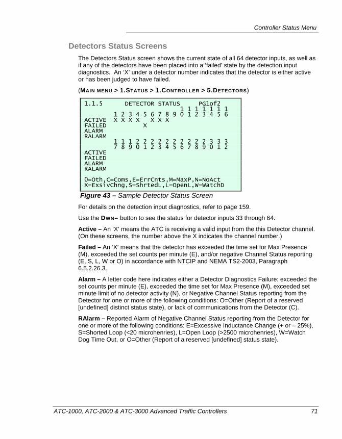
Controller Status Menu
ATC-1000, ATC-2000 & ATC-3000 Advanced Traffic Controllers 71
Detectors Status Screens The Detectors Status screen shows the current state of all 64 detector inputs, as well as if any of the detectors have been placed into a ‘failed’ state by the detection input diagnostics. An ‘X’ under a detector number indicates that the detector is either active or has been judged to have failed.
(MAIN MENU > 1.STATUS > 1.CONTROLLER > 5.DETECTORS)
1.1.5 DETECTOR STATUS PG1of2 1 1 1 1 1 1 1 1 2 3 4 5 6 7 8 9 0 1 2 3 4 5 6 ACTIVE X X X X X X X FAILED X ALARM RALARM 1 1 1 2 2 2 2 2 2 2 2 2 2 3 3 3 7 8 9 0 1 2 3 4 5 6 7 8 9 0 1 2 ACTIVE FAILED ALARM RALARM 0=Oth,C=Coms,E=ErrCnts,M=MaxP,N=NoAct X=ExsivChng,S=ShrtedL,L=OpenL,W=WatchD
Figure 43 – Sample Detector Status Screen For details on the detection input diagnostics, refer to page 159.
Use the DWN– button to see the status for detector inputs 33 through 64.
Active – An ‘X’ means the ATC is receiving a valid input from the this Detector channel. (On these screens, the number above the X indicates the channel number.)
Failed – An ‘X’ means that the detector has exceeded the time set for Max Presence (M), exceeded the set counts per minute (E), and/or negative Channel Status reporting (E, S, L, W or O) in accordance with NTCIP and NEMA TS2-2003, Paragraph 6.5.2.26.3.
Alarm – A letter code here indicates either a Detector Diagnostics Failure: exceeded the set counts per minute (E), exceeded the time set for Max Presence (M), exceeded set minute limit of no detector activity (N), or Negative Channel Status reporting from the Detector for one or more of the following conditions: O=Other (Report of a reserved [undefined] distinct status state), or lack of communications from the Detector (C).
RAlarm – Reported Alarm of Negative Channel Status reporting from the Detector for one or more of the following conditions: E=Excessive Inductance Change (+ or – 25%), S=Shorted Loop (<20 microhenries), L=Open Loop (>2500 microhenries), W=Watch Dog Time Out, or O=Other (Report of a reserved [undefined] status state).
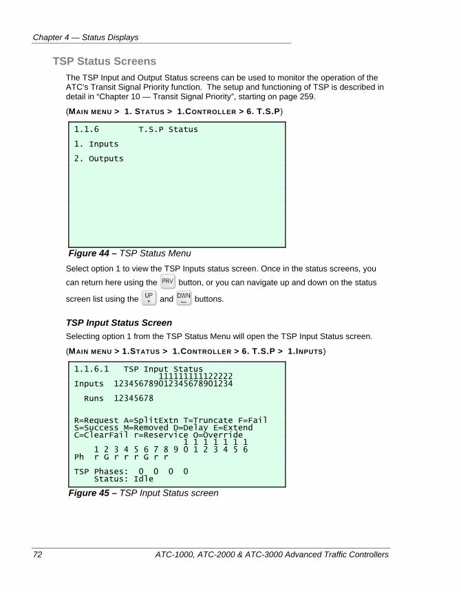
Chapter 4 — Status Displays
72 ATC-1000, ATC-2000 & ATC-3000 Advanced Traffic Controllers
TSP Status Screens The TSP Input and Output Status screens can be used to monitor the operation of the ATC’s Transit Signal Priority function. The setup and functioning of TSP is described in detail in “Chapter 10 — Transit Signal Priority”, starting on page 259.
(MAIN MENU > 1. STATUS > 1.CONTROLLER > 6. T.S.P)
1.1.6 T.S.P Status 1. Inputs 2. Outputs
Figure 44 – TSP Status Menu Select option 1 to view the TSP Inputs status screen. Once in the status screens, you
can return here using the button, or you can navigate up and down on the status
screen list using the and buttons.
TSP Input Status Screen Selecting option 1 from the TSP Status Menu will open the TSP Input Status screen.
(MAIN MENU > 1.STATUS > 1.CONTROLLER > 6. T.S.P > 1.INPUTS)
1.1.6.1 TSP Input Status 111111111122222 Inputs 123456789012345678901234 Runs 12345678 R=Request A=SplitExtn T=Truncate F=Fail S=Success M=Removed D=Delay E=Extend C=ClearFail r=Reservice O=Override 1 1 1 1 1 1 1 1 2 3 4 5 6 7 8 9 0 1 2 3 4 5 6 Ph r G r r r G r r TSP Phases: 0 0 0 0 Status: Idle
Figure 45 – TSP Input Status screen
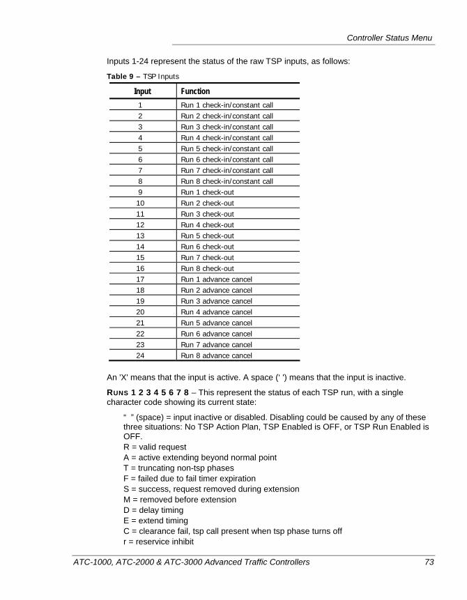
Controller Status Menu
ATC-1000, ATC-2000 & ATC-3000 Advanced Traffic Controllers 73
Inputs 1-24 represent the status of the raw TSP inputs, as follows:
Table 9 – TSP Inputs
Input Function 1 Run 1 check-in/constant call 2 Run 2 check-in/constant call 3 Run 3 check-in/constant call 4 Run 4 check-in/constant call 5 Run 5 check-in/constant call 6 Run 6 check-in/constant call 7 Run 7 check-in/constant call 8 Run 8 check-in/constant call 9 Run 1 check-out
10 Run 2 check-out 11 Run 3 check-out 12 Run 4 check-out 13 Run 5 check-out 14 Run 6 check-out 15 Run 7 check-out 16 Run 8 check-out 17 Run 1 advance cancel 18 Run 2 advance cancel 19 Run 3 advance cancel 20 Run 4 advance cancel 21 Run 5 advance cancel 22 Run 6 advance cancel 23 Run 7 advance cancel 24 Run 8 advance cancel
An 'X' means that the input is active. A space (‘ ') means that the input is inactive.
RUNS 1 2 3 4 5 6 7 8 – This represent the status of each TSP run, with a single character code showing its current state:
“ ” (space) = input inactive or disabled. Disabling could be caused by any of these three situations: No TSP Action Plan, TSP Enabled is OFF, or TSP Run Enabled is OFF. R = valid request A = active extending beyond normal point T = truncating non-tsp phases F = failed due to fail timer expiration S = success, request removed during extension M = removed before extension D = delay timing E = extend timing C = clearance fail, tsp call present when tsp phase turns off r = reservice inhibit
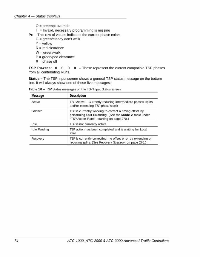
Chapter 4 — Status Displays
74 ATC-1000, ATC-2000 & ATC-3000 Advanced Traffic Controllers
O = preempt override I = Invalid, necessary programming is missing
PH – This row of values indicates the current phase color: G = green/steady don’t walk Y = yellow R = red clearance W = green/walk P = green/ped clearance R = phase off
TSP PHASES: 0 0 0 0 – These represent the current compatible TSP phases from all contributing Runs.
Status – The TSP input screen shows a general TSP status message on the bottom line. It will always show one of these five messages:
Table 10 – TSP Status messages on the TSP Input Status screen
Message Description Active TSP Active - Currently reducing intermediate phases’ splits
and/or extending TSP phase’s split
Balance TSP is currently working to correct a timing offset by performing Split Balancing. (See the Mode 2 topic under “TSP Action Plans”, starting on page 270.)
Idle TSP is not currently active
Idle Pending TSP action has been completed and is waiting for Local Zero
Recovery TSP is currently correcting the offset error by extending or reducing splits. (See Recovery Strategy, on page 270.)
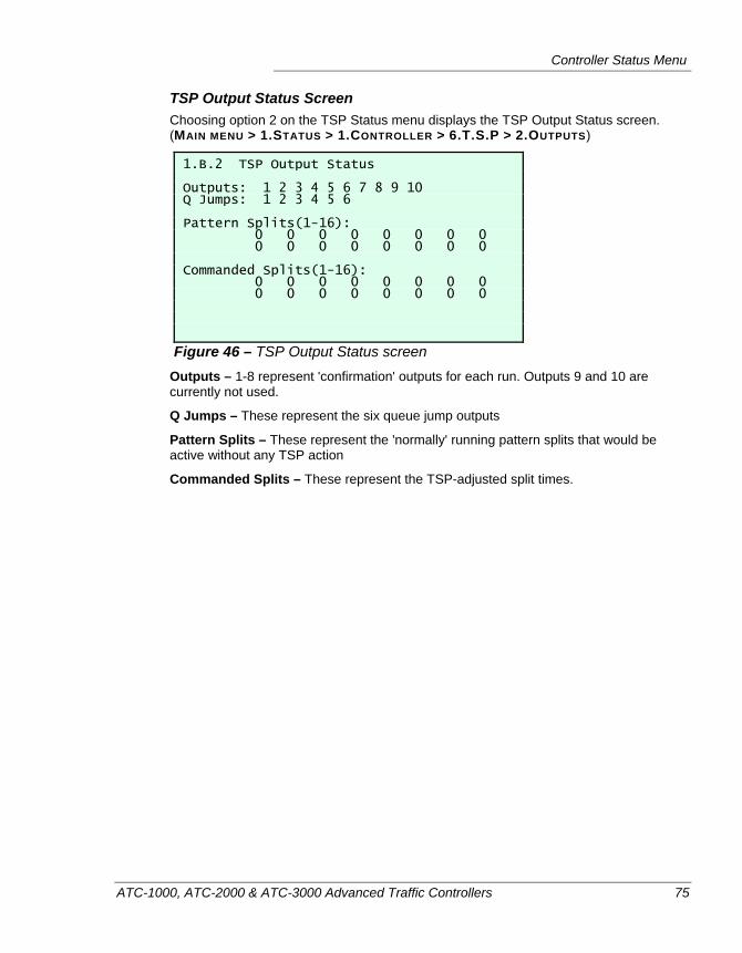
Controller Status Menu
ATC-1000, ATC-2000 & ATC-3000 Advanced Traffic Controllers 75
TSP Output Status Screen Choosing option 2 on the TSP Status menu displays the TSP Output Status screen. (MAIN MENU > 1.STATUS > 1.CONTROLLER > 6.T.S.P > 2.OUTPUTS)
1.B.2 TSP Output Status Outputs: 1 2 3 4 5 6 7 8 9 10 Q Jumps: 1 2 3 4 5 6 Pattern Splits(1-16): 0 0 0 0 0 0 0 0 0 0 0 0 0 0 0 0 Commanded Splits(1-16): 0 0 0 0 0 0 0 0 0 0 0 0 0 0 0 0
Figure 46 – TSP Output Status screen Outputs – 1-8 represent 'confirmation' outputs for each run. Outputs 9 and 10 are currently not used.
Q Jumps – These represent the six queue jump outputs
Pattern Splits – These represent the 'normally' running pattern splits that would be active without any TSP action
Commanded Splits – These represent the TSP-adjusted split times.
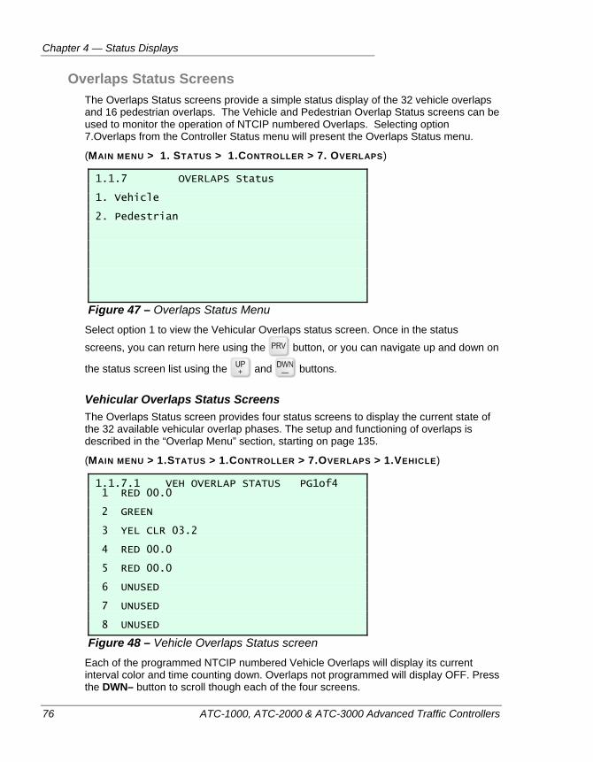
Chapter 4 — Status Displays
76 ATC-1000, ATC-2000 & ATC-3000 Advanced Traffic Controllers
Overlaps Status Screens The Overlaps Status screens provide a simple status display of the 32 vehicle overlaps and 16 pedestrian overlaps. The Vehicle and Pedestrian Overlap Status screens can be used to monitor the operation of NTCIP numbered Overlaps. Selecting option 7.Overlaps from the Controller Status menu will present the Overlaps Status menu.
(MAIN MENU > 1. STATUS > 1.CONTROLLER > 7. OVERLAPS)
1.1.7 OVERLAPS Status 1. Vehicle 2. Pedestrian
Figure 47 – Overlaps Status Menu Select option 1 to view the Vehicular Overlaps status screen. Once in the status
screens, you can return here using the button, or you can navigate up and down on
the status screen list using the and buttons.
Vehicular Overlaps Status Screens The Overlaps Status screen provides four status screens to display the current state of the 32 available vehicular overlap phases. The setup and functioning of overlaps is described in the “Overlap Menu” section, starting on page 135.
(MAIN MENU > 1.STATUS > 1.CONTROLLER > 7.OVERLAPS > 1.VEHICLE)
1.1.7.1 VEH OVERLAP STATUS PG1of4 1 RED 00.0 2 GREEN 3 YEL CLR 03.2 4 RED 00.0 5 RED 00.0 6 UNUSED 7 UNUSED 8 UNUSED
Figure 48 – Vehicle Overlaps Status screen Each of the programmed NTCIP numbered Vehicle Overlaps will display its current interval color and time counting down. Overlaps not programmed will display OFF. Press the DWN– button to scroll though each of the four screens.
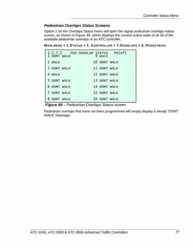
Controller Status Menu
ATC-1000, ATC-2000 & ATC-3000 Advanced Traffic Controllers 77
Pedestrian Overlaps Status Screens Option 2 on the Overlaps Status menu will open the signal pedestrian overlaps status screen, as shown in Figure 49, which displays the current output state of all 16 of the available pedestrian overlaps of an ATC controller.
MAIN MENU > 1.STATUS > 1. CONTROLLER > 7.OVERLAPS > 2. PEDESTRIAN
1.1.7.2 PED OVERLAP STATUS PG1of1 1 DONT WALK 9 WALK 2 WALK 10 DONT WALK 3 DONT WALK 11 DONT WALK 4 WALK 12 DONT WALK 5 DONT WALK 13 DONT WALK 6 DONT WALK 14 DONT WALK 7 DONT WALK 15 DONT WALK 8 DONT WALK 16 DONT WALK
Figure 49 – Pedestrian Overlaps Status screen Pedestrian overlaps that have not been programmed will simply display a steady ‘DONT WALK’ message.
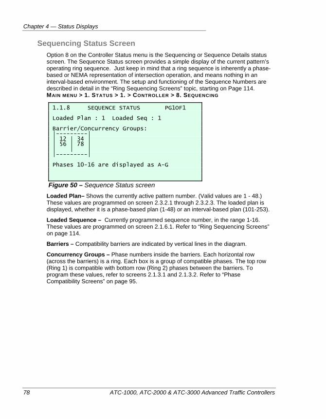
Chapter 4 — Status Displays
78 ATC-1000, ATC-2000 & ATC-3000 Advanced Traffic Controllers
Sequencing Status Screen Option 8 on the Controller Status menu is the Sequencing or Sequence Details status screen. The Sequence Status screen provides a simple display of the current pattern’s operating ring sequence. Just keep in mind that a ring sequence is inherently a phase-based or NEMA representation of intersection operation, and means nothing in an interval-based environment. The setup and functioning of the Sequence Numbers are described in detail in the “Ring Sequencing Screens” topic, starting on Page 114. MAIN MENU > 1. STATUS > 1. > CONTROLLER > 8. SEQUENCING
1.1.8 SEQUENCE STATUS PG1OF1 Loaded Plan : 1 Loaded Seq : 1 Barrier/Concurrency Groups: |---------| | 12 | 34 | | 56 | 78 | | | | |---------| Phases 10-16 are displayed as A-G
Figure 50 – Sequence Status screen Loaded Plan– Shows the currently active pattern number. (Valid values are 1 - 48.) These values are programmed on screen 2.3.2.1 through 2.3.2.3. The loaded plan is displayed, whether it is a phase-based plan (1-48) or an interval-based plan (101-253).
Loaded Sequence – Currently programmed sequence number, in the range 1-16. These values are programmed on screen 2.1.6.1. Refer to “Ring Sequencing Screens” on page 114.
Barriers – Compatibility barriers are indicated by vertical lines in the diagram.
Concurrency Groups – Phase numbers inside the barriers. Each horizontal row (across the barriers) is a ring. Each box is a group of compatible phases. The top row (Ring 1) is compatible with bottom row (Ring 2) phases between the barriers. To program these values, refer to screens 2.1.3.1 and 2.1.3.2. Refer to “Phase Compatibility Screens” on page 95.
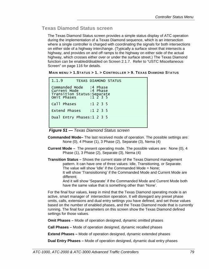
Controller Status Menu
ATC-1000, ATC-2000 & ATC-3000 Advanced Traffic Controllers 79
Texas Diamond Status screen The Texas Diamond Status screen provides a simple status display of ATC operation during the implementation of a Texas Diamond sequence, which is an intersection where a single controller is charged with coordinating the signals for both intersections on either side of a highway interchange. (Typically a surface street that intersects a highway, and provides on and off ramps to the highway on either side of the actual highway, which crosses either over or under the surface street.) The Texas Diamond function can be enabled/disabled on Screen 2.1.7. Refer to “USTC Miscellaneous Screen” on page 116 for details.
MAIN MENU > 1.STATUS > 1. > CONTROLLER > 9. TEXAS DIAMOND STATUS
1.1.9 TEXAS DIAMOND STATUS Commanded Mode :4 Phase Current Mode :4 Phase Transition Status:Separate Omit Phases :1 2 3 5 Call Phases :1 2 3 5 Extend Phases :1 2 3 5 Dual Entry Phases:1 2 3 5
Figure 51 — Texas Diamond Status screen Commanded Mode– The last received mode of operation. The possible settings are:
None (0), 4 Phase (1), 3 Phase (2), Separate (3), Nema (4)
Current Mode – The present operating mode. The possible values are: None (0), 4 Phase (1), 3 Phase (2), Separate (3), Nema (4)
Transition Status – Shows the current state of the Texas Diamond management pattern. It can have one of three values: Idle, Transitioning, or Separate. The value will show ‘Idle’ if the Commanded Mode = None; It will show ‘Transisitioning’ if the Commanded Mode and Current Mode are different; And it will show ‘Separate’ if the Commanded Mode and Current Mode both have the same value that is something other than ‘None’.
For the final four values, keep in mind that the Texas Diamond operating mode is an active, smart manager of intersection operation. It will disregard any preset phase omits, calls, extensions and dual entry settings you have defined, and set those values based on the number of enabled phases, and the Texas Diamond mode that is currently running. The final four parameters on this screen show the Texas Diamond defined settings for those values.
Omit Phases – Mode of operation designed, dynamic omitted phases
Call Phases – Mode of operation designed, dynamic recalled phases
Extend Phases – Mode of operation designed, dynamic extended phases
Dual Entry Phases – Mode of operation designed, dynamic dual entry phases
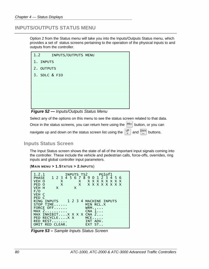
Chapter 4 — Status Displays
80 ATC-1000, ATC-2000 & ATC-3000 Advanced Traffic Controllers
INPUTS/OUTPUTS STATUS MENU
Option 2 from the Status menu will take you into the Inputs/Outputs Status menu, which provides a set of status screens pertaining to the operation of the physical inputs to and outputs from the controller.
1.2 INPUTS/OUTPUTS MENU 1. INPUTS 2. OUTPUTS 3. SDLC & FIO
Figure 52 — Inputs/Outputs Status Menu Select any of the options on this menu to see the status screen related to that data.
Once in the status screens, you can return here using the button, or you can
navigate up and down on the status screen list using the and buttons.
Inputs Status Screen The Input Status screen shows the state of all of the important input signals coming into the controller. These include the vehicle and pedestrian calls, force-offs, overrides, ring inputs and global controller input parameters.
(MAIN MENU > 1.STATUS > 2.INPUTS)
1.2.1 INPUTS TS2 PG1of1 PHASE 1 2 3 4 5 6 7 8 9 0 1 2 3 4 5 6 VEH O X X X X X X X X X X PED O X X X X X X X X X X VEH H X X F/O VEH C PED C RING INPUTS 1 2 3 4 MACHINE INPUTS STOP TIME...... MIN RCL.X FORCE OFF...... WRM..... MAX 2.......... CNA 1... MAX INHIBIT....X X X X CNA 2... PED RECYCLE....X X MCE..... RED REST....... INT ADV. OMIT RED CLEAR. EXT ST..
Figure 53 – Sample Inputs Status Screen
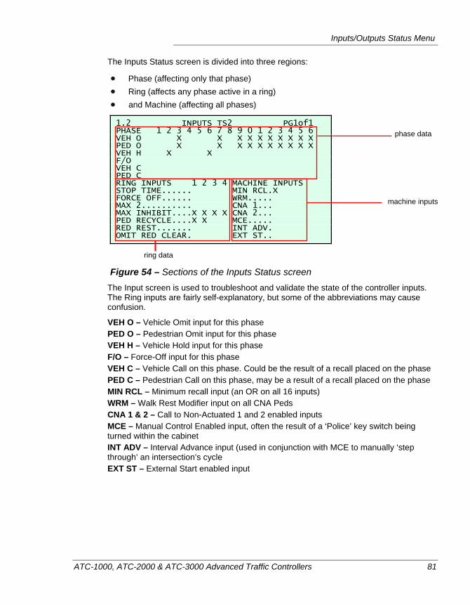
Inputs/Outputs Status Menu
ATC-1000, ATC-2000 & ATC-3000 Advanced Traffic Controllers 81
The Inputs Status screen is divided into three regions:
Phase (affecting only that phase) Ring (affects any phase active in a ring) and Machine (affecting all phases)
1.2 INPUTS TS2 PG1of1 PHASE 1 2 3 4 5 6 7 8 9 0 1 2 3 4 5 6 VEH O X X X X X X X X X X PED O X X X X X X X X X X VEH H X X F/O VEH C PED C RING INPUTS 1 2 3 4 MACHINE INPUTS STOP TIME...... MIN RCL.X FORCE OFF...... WRM..... MAX 2.......... CNA 1... MAX INHIBIT....X X X X CNA 2... PED RECYCLE....X X MCE..... RED REST....... INT ADV. OMIT RED CLEAR. EXT ST..
Figure 54 – Sections of the Inputs Status screen The Input screen is used to troubleshoot and validate the state of the controller inputs. The Ring inputs are fairly self-explanatory, but some of the abbreviations may cause confusion.
VEH O – Vehicle Omit input for this phase PED O – Pedestrian Omit input for this phase VEH H – Vehicle Hold input for this phase F/O – Force-Off input for this phase VEH C – Vehicle Call on this phase. Could be the result of a recall placed on the phase PED C – Pedestrian Call on this phase, may be a result of a recall placed on the phase MIN RCL – Minimum recall input (an OR on all 16 inputs) WRM – Walk Rest Modifier input on all CNA Peds CNA 1 & 2 – Call to Non-Actuated 1 and 2 enabled inputs MCE – Manual Control Enabled input, often the result of a ‘Police’ key switch being turned within the cabinet INT ADV – Interval Advance input (used in conjunction with MCE to manually ‘step through’ an intersection’s cycle EXT ST – External Start enabled input
phase data
ring data
machine inputs
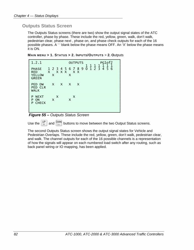
Chapter 4 — Status Displays
82 ATC-1000, ATC-2000 & ATC-3000 Advanced Traffic Controllers
Outputs Status Screen The Outputs Status screens (there are two) show the output signal states of the ATC controller, phase by phase. These include the red, yellow, green, walk, don’t walk, pedestrian clear, phase next , phase on, and phase check outputs for each of the 16 possible phases. A ‘ ‘ blank below the phase means OFF. An ‘X’ below the phase means it is ON.
MAIN MENU > 1. STATUS > 2. INPUTS/OUTPUTS > 2. Outputs
1.2.1 OUTPUTS PG1of2 1 1 1 1 1 1 1 PHASE 1 2 3 4 5 6 7 8 9 0 1 2 3 4 5 6 RED X X X X X X YELLOW X X GREEN PED DW X X X X PED CLR WALK P NEXT X X P ON X X P CHECK
Figure 55 – Outputs Status Screen
Use the and buttons to move between the two Output Status screens.
The second Outputs Status screen shows the output signal states for Vehicle and Pedestrian Overlaps. These include the red, yellow, green, don’t walk, pedestrian clear, and walk. The channel outputs for each of the 16 possible channels is a representation of how the signals will appear on each numbered load switch after any routing, such as back panel wiring or IO mapping, has been applied.
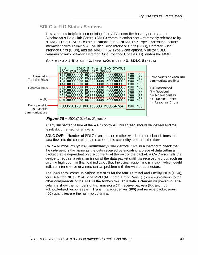
Inputs/Outputs Status Menu
ATC-1000, ATC-2000 & ATC-3000 Advanced Traffic Controllers 83
SDLC & FIO Status Screens This screen is helpful in determining if the ATC controller has any errors on the Synchronous Data Link Control (SDLC) communication port – commonly referred to by NEMA as Port 1. SDLC communications during NEMA TS2 Type 1 operation include interactions with Terminal & Facilities Buss Interface Units (BIUs), Detector Buss Interface Units (BIUs), and the MMU. TS2 Type 2 can optionally utilize SDLC communications between Detector Buss Interface Units (BIUs), and/or the MMU.
MAIN MENU > 1.STATUS > 2. INPUTS/OUTPUTS > 3. SDLC STATUS)
1.8 SDLC & Field I/O STATUS SDLC OVR:00000 CRC:00000 T1T00000000 R00000000 n00000000 t00 r00 T2T00000000 R00000000 n00000000 t00 r00 T3T00000000 R00000000 n00000000 t00 r00 T4T00000000 R00000000 n00000000 t00 r00 D1T00000000 R00000000 n00000000 t00 r00 D2T00000000 R00000000 n00000000 t00 r00 D3T00000000 R00000000 n00000000 t00 r00 D4T00000000 R00000000 n00000000 t00 r00 MUT00000000 R00000000 n00000000 t00 r00 F000550179 R00183393 n00366784 t00 r00
Figure 56 – SDLC Status Screens At any suspected failure of the ATC controller, this screen should be viewed and the result documented for analysis.
SDLC OVR – Number of SDLC overruns, or in other words, the number of times the data flow into the controller has exceeded its capability to handle the flow.
CRC – Number of Cyclical Redundancy Check errors. CRC is a method to check that the data sent is the same as the data received by encoding a piece of data within a packet that is dependent on the contents of the rest of the packet. A CRC error tells the device to request a retransmission of the data packet until it is received without such an error. A high count in this field indicates that the transmission line is ‘noisy’, which could indicate interference or a mechanical problem with the wire or connectors.
The rows show communications statistics for the four Terminal and Facility BIUs (T1-4), four Detector BIUs (D1-4), and MMU (MU) data. Front Panel (F) communications to the other components of the ATC is the bottom row. This data is cleared on power up. The columns show the numbers of transmissions (T), receive packets (R), and not acknowledged responses (n). Transmit packet errors (t00) and receive packet errors (r00) quantities are the last two columns.
Error counts on each BIU communications line: T = Transmitted R = Received n = No Responses t = Transmit Errors r = Response Errors
Terminal & Facilities BIUs
Detector BIUs
MMU
Front panel toI/O Module
communications
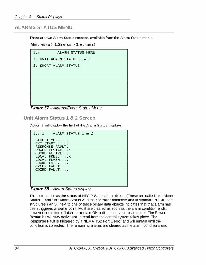
Chapter 4 — Status Displays
84 ATC-1000, ATC-2000 & ATC-3000 Advanced Traffic Controllers
ALARMS STATUS MENU
There are two Alarm Status screens, available from the Alarm Status menu.
(MAIN MENU > 1.STATUS > 3.ALARMS)
1.3 ALARM STATUS MENU 1. UNIT ALARM STATUS 1 & 2 2. SHORT ALARM STATUS
Figure 57 – Alarms/Event Status Menu
Unit Alarm Status 1 & 2 Screen Option 1 will display the first of the Alarm Status displays.
1.3.1 ALARM STATUS 1 & 2 STOP TIME...... EXT START...... RESPONSE FAULT. POWER RESTART..X COORD ACTIVE... LOCAL FREE.....X LOCAL FLASH.... COORD FAIL..... CYCLE FAULT.... COORD FAULT....
Figure 58 – Alarm Status display This screen shows the status of NTCIP Status data objects (These are called ‘unit Alarm Status 1’ and ‘unit Alarm Status 2’ in the controller database and in standard NTCIP data structures.) An ‘X’ next to one of these binary data objects indicates that that alarm has been triggered at some point. Most are cleared as soon as the alarm condition ends, however some items ‘latch’, or remain ON until some event clears them. The Power Restart bit will stay active until a read from the central system takes place. The Response Fault is triggered by a NEMA TS2 Port 1 error and will remain until the condition is corrected. The remaining alarms are cleared as the alarm conditions end.
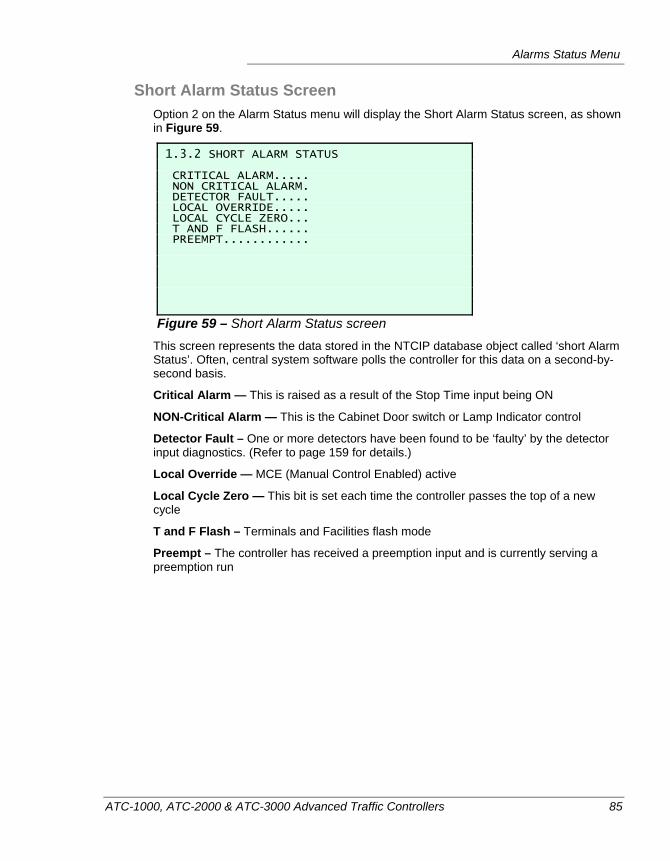
Alarms Status Menu
ATC-1000, ATC-2000 & ATC-3000 Advanced Traffic Controllers 85
Short Alarm Status Screen Option 2 on the Alarm Status menu will display the Short Alarm Status screen, as shown in Figure 59.
1.3.2 SHORT ALARM STATUS CRITICAL ALARM..... NON CRITICAL ALARM. DETECTOR FAULT..... LOCAL OVERRIDE..... LOCAL CYCLE ZERO... T AND F FLASH...... PREEMPT............
Figure 59 – Short Alarm Status screen This screen represents the data stored in the NTCIP database object called ‘short Alarm Status’. Often, central system software polls the controller for this data on a second-by-second basis.
Critical Alarm — This is raised as a result of the Stop Time input being ON
NON-Critical Alarm — This is the Cabinet Door switch or Lamp Indicator control
Detector Fault – One or more detectors have been found to be ‘faulty’ by the detector input diagnostics. (Refer to page 159 for details.)
Local Override — MCE (Manual Control Enabled) active
Local Cycle Zero — This bit is set each time the controller passes the top of a new cycle
T and F Flash – Terminals and Facilities flash mode
Preempt – The controller has received a preemption input and is currently serving a preemption run
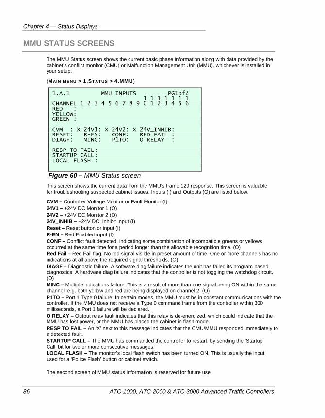
Chapter 4 — Status Displays
86 ATC-1000, ATC-2000 & ATC-3000 Advanced Traffic Controllers
MMU STATUS SCREENS
The MMU Status screen shows the current basic phase information along with data provided by the cabinet’s conflict monitor (CMU) or Malfunction Management Unit (MMU), whichever is installed in your setup.
(MAIN MENU > 1.STATUS > 4.MMU)
1.A.1 MMU INPUTS PG1of2 1 1 1 1 1 1 1 CHANNEL 1 2 3 4 5 6 7 8 9 0 1 2 3 4 5 6 RED : YELLOW: GREEN : CVM : X 24V1: X 24V2: X 24V_INHIB: RESET: R-EN: CONF: RED FAIL : DIAGF: MINC: P1TO: O RELAY : RESP TO FAIL: STARTUP CALL: LOCAL FLASH :
Figure 60 – MMU Status screen This screen shows the current data from the MMU’s frame 129 response. This screen is valuable for troubleshooting suspected cabinet issues. Inputs (I) and Outputs (O) are listed below.
CVM – Controller Voltage Monitor or Fault Monitor (I) 24V1 – +24V DC Monitor 1 (O) 24V2 – +24V DC Monitor 2 (O) 24V_INHIB – +24V DC Inhibit Input (I) Reset – Reset button or input (I) R-EN – Red Enabled input (I) CONF – Conflict fault detected, indicating some combination of incompatible greens or yellows occurred at the same time for a period longer than the allowable recognition time. (O) Red Fail – Red Fail flag. No red signal visible in preset amount of time. One or more channels has no indications at all above the required signal thresholds. (O) DIAGF – Diagnostic failure. A software diag failure indicates the unit has failed its program-based diagnostics. A hardware diag failure indicates that the controller is not toggling the watchdog circuit. (O) MINC – Multiple indications failure. This is a result of more than one signal being ON within the same channel, e.g. both yellow and red are being displayed on channel 2. (O) P1TO – Port 1 Type 0 failure. In certain modes, the MMU must be in constant communications with the controller. If the MMU does not receive a Type 0 command frame from the controller within 300 milliseconds, a Port 1 failure will be declared. O RELAY – Output relay fault indicates that this relay is de-energized, which could indicate that the MMU has lost power, or the MMU has placed the cabinet in flash mode. RESP TO FAIL – An ‘X’ next to this message indicates that the CMU/MMU responded immediately to a detected fault. STARTUP CALL – The MMU has commanded the controller to restart, by sending the ‘Startup Call’ bit for two or more consecutive messages. LOCAL FLASH – The monitor’s local flash switch has been turned ON. This is usually the input used for a ‘Police Flash’ button or cabinet switch. The second screen of MMU status information is reserved for future use.
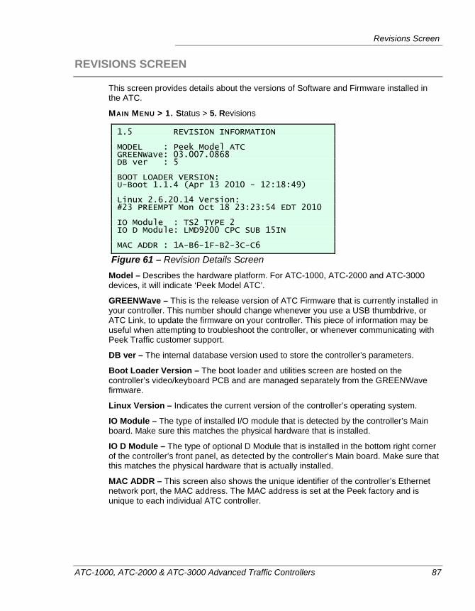
Revisions Screen
ATC-1000, ATC-2000 & ATC-3000 Advanced Traffic Controllers 87
REVISIONS SCREEN
This screen provides details about the versions of Software and Firmware installed in the ATC.
MAIN MENU > 1. Status > 5. Revisions
1.5 REVISION INFORMATION MODEL : Peek Model ATC GREENWave: 03.007.0868 DB ver : 5 BOOT LOADER VERSION: U-Boot 1.1.4 (Apr 13 2010 - 12:18:49) Linux 2.6.20.14 Version: #23 PREEMPT Mon Oct 18 23:23:54 EDT 2010 IO Module : TS2 TYPE 2 IO D Module: LMD9200 CPC SUB 15IN MAC ADDR : 1A-B6-1F-B2-3C-C6
Figure 61 – Revision Details Screen Model – Describes the hardware platform. For ATC-1000, ATC-2000 and ATC-3000 devices, it will indicate ‘Peek Model ATC’.
GREENWave – This is the release version of ATC Firmware that is currently installed in your controller. This number should change whenever you use a USB thumbdrive, or ATC Link, to update the firmware on your controller. This piece of information may be useful when attempting to troubleshoot the controller, or whenever communicating with Peek Traffic customer support.
DB ver – The internal database version used to store the controller’s parameters.
Boot Loader Version – The boot loader and utilities screen are hosted on the controller’s video/keyboard PCB and are managed separately from the GREENWave firmware.
Linux Version – Indicates the current version of the controller’s operating system.
IO Module – The type of installed I/O module that is detected by the controller’s Main board. Make sure this matches the physical hardware that is installed.
IO D Module – The type of optional D Module that is installed in the bottom right corner of the controller’s front panel, as detected by the controller’s Main board. Make sure that this matches the physical hardware that is actually installed.
MAC ADDR – This screen also shows the unique identifier of the controller’s Ethernet network port, the MAC address. The MAC address is set at the Peek factory and is unique to each individual ATC controller.

Chapter 4 — Status Displays
88 ATC-1000, ATC-2000 & ATC-3000 Advanced Traffic Controllers
ATC-1000, ATC-2000 & ATC-3000 Advanced Traffic Controllers 89
Chapter 5 — Programming Menus
This chapter describes the non-status portion of the controller menu system, including the Programming menus, the System Maintenance menus, and the Log screens. The following topics are discussed in detail:
• Overview of the Programming screens, on page 90.
• Unit Configuration screens, on page 90.
• Controller configuration screens, on page 119.
• Coordination configuration screens, on page 136.
• Time of Day configuration screens, on page 143.
• Detectors configuration screens, on page 157.
• Preemption configuration screens, on page 164.
• Interval configuration, on page 165.
• Transit Signal Priority configuration, on page 166.
• Using the System Maintenance screens, on page 167.
• Using the Logs screens, on page 174.
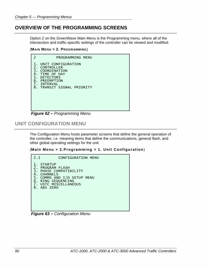
Chapter 5 — Programming Menus
90 ATC-1000, ATC-2000 & ATC-3000 Advanced Traffic Controllers
OVERVIEW OF THE PROGRAMMING SCREENS
Option 2 on the GreenWave Main Menu is the Programming menu, where all of the intersection and traffic-specific settings of the controller can be viewed and modified.
(MAIN MENU > 2. PROGRAMMING)
2 PROGRAMMING MENU 1. UNIT CONFIGURATION 2. CONTROLLER 3. COORDINATION 4. TIME OF DAY 5. DETECTORS 6. PREEMPTION 7. INTERVAL 8. TRANSIT SIGNAL PRIORITY
Figure 62 – Programming Menu
UNIT CONFIGURATION MENU
The Configuration Menu hosts parameter screens that define the general operation of the controller, i.e. meaning items that define the communications, general flash, and other global operating settings for the unit.
(Main Menu > 2.Programming > 1. Unit Configurat ion )
2.1 CONFIGURATION MENU 1. STARTUP 2. PROGRAM FLASH 3. PHASE COMPATIBILITY 4. CHANNELS 5. COMMS AND I/O SETUP MENU 6. RING SEQUENCING 7. USTC MISCELLANEOUS 8. ABS ZERO
Figure 63 – Configuration Menu
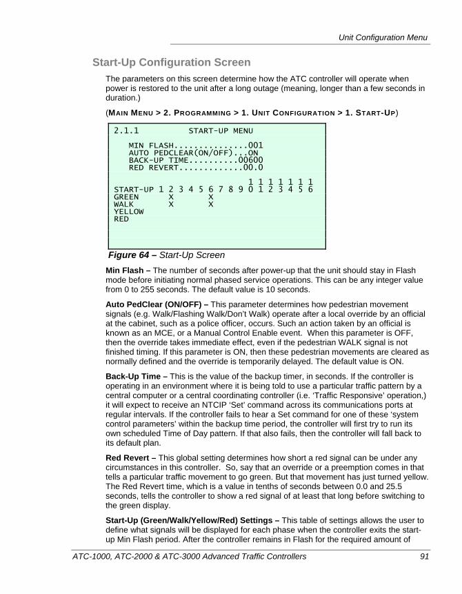
Unit Configuration Menu
ATC-1000, ATC-2000 & ATC-3000 Advanced Traffic Controllers 91
Start-Up Configuration Screen The parameters on this screen determine how the ATC controller will operate when power is restored to the unit after a long outage (meaning, longer than a few seconds in duration.)
(MAIN MENU > 2. PROGRAMMING > 1. UNIT CONFIGURATION > 1. START-UP)
2.1.1 START-UP MENU MIN FLASH...............001 AUTO PEDCLEAR(ON/OFF)...ON BACK-UP TIME..........00600 RED REVERT.............00.0 1 1 1 1 1 1 1 START-UP 1 2 3 4 5 6 7 8 9 0 1 2 3 4 5 6 GREEN X X WALK X X YELLOW RED
Figure 64 – Start-Up Screen Min Flash – The number of seconds after power-up that the unit should stay in Flash mode before initiating normal phased service operations. This can be any integer value from 0 to 255 seconds. The default value is 10 seconds.
Auto PedClear (ON/OFF) – This parameter determines how pedestrian movement signals (e.g. Walk/Flashing Walk/Don’t Walk) operate after a local override by an official at the cabinet, such as a police officer, occurs. Such an action taken by an official is known as an MCE, or a Manual Control Enable event. When this parameter is OFF, then the override takes immediate effect, even if the pedestrian WALK signal is not finished timing. If this parameter is ON, then these pedestrian movements are cleared as normally defined and the override is temporarily delayed. The default value is ON.
Back-Up Time – This is the value of the backup timer, in seconds. If the controller is operating in an environment where it is being told to use a particular traffic pattern by a central computer or a central coordinating controller (i.e. ‘Traffic Responsive’ operation,) it will expect to receive an NTCIP ‘Set’ command across its communications ports at regular intervals. If the controller fails to hear a Set command for one of these ‘system control parameters’ within the backup time period, the controller will first try to run its own scheduled Time of Day pattern. If that also fails, then the controller will fall back to its default plan.
Red Revert – This global setting determines how short a red signal can be under any circumstances in this controller. So, say that an override or a preemption comes in that tells a particular traffic movement to go green. But that movement has just turned yellow. The Red Revert time, which is a value in tenths of seconds between 0.0 and 25.5 seconds, tells the controller to show a red signal of at least that long before switching to the green display.
Start-Up (Green/Walk/Yellow/Red) Settings – This table of settings allows the user to define what signals will be displayed for each phase when the controller exits the start-up Min Flash period. After the controller remains in Flash for the required amount of
Chapter 5 — Programming Menus
92 ATC-1000, ATC-2000 & ATC-3000 Advanced Traffic Controllers
time, these settings serve as the initial state of all of the intersection’s phases. Once these phase signal states are in place, normal operation of the intersection can begin. It is important to remember to follow safety rules when setting these phase states. The controller will not allow an unsafe initial condition to be entered, but it does not monitor these inputs as you enter them. It merely checks to see if the whole table is valid when
you use the - key combination to commit the changes to the controller’s database. If any invalid phase settings exist, for example if you’ve set more than one color for a phase, you will see an error screen and be required to make changes. The error message does not indicate ALL of the problems with the table, merely the first one that was discovered.
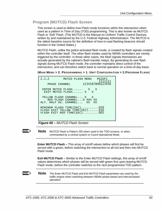
Unit Configuration Menu
ATC-1000, ATC-2000 & ATC-3000 Advanced Traffic Controllers 93
Program (MUTCD) Flash Screen This screen is used to define how Flash mode functions within the intersection when used as a pattern in Time of Day (TOD) programming. This is also known as MUTCD Flash or ‘Soft’ Flash. (The MUTCD is the Manual on Uniform Traffic Control Devices, written by and maintained by the U.S. Federal Highway Administration. The MUTCD is the oldest baseline source for the definition of how in-road flashing beacons should function in the United States.)
MUTCD Flash, unlike the police-activated flash mode, is created by flash signals created within the controller itself. The other flash modes used by NEMA controllers are merely triggered by the controller; in those other cases, the flash signals themselves are actually generated by the cabinet’s flash transfer relays. By generating its own flash signals during MUTCD Flash mode, the controller maintains direct control of the intersection, and can therefore switch back to normal operation on a time-of-day basis.
(MAIN MENU > 2. PROGRAMMING > 1. UNIT CONFIGURATION > 2.PROGRAM FLASH)
2.1.2 MUTCD FLASH MENU PG1OF1 1111111 PHASE CHANNEL 1234567890123456 ENTER MUTCD FLASH...... X X EXIT MUTCD FLASH...... X X YELLOW FLASH CHANNEL... X X RED FLASH CHANNEL...X XXX XX ALT. HALF HZ. CHANNEL... XX XX MINIMUM FLASH TIME(SEC)..........010 FLASH EXIT YELLOW TIME(SEC)......010 FLASH EXIT RED TIME(SEC).........005
Figure 65 – MUTCD Flash Screen
Note MUTCD Flash is Pattern 255 when used in the TOD screens, or when commanded by a central system or Coord Operational Mode.
Enter MUTCD Flash – This array of on/off values define which phases will first be served with a green, before switching the intersection to all red and then into MUTCD Flash mode.
Exit MUTCD Flash – Similar to the Enter MUTCD Flash settings, this array of on/off values determines which phases will be served with green first upon leaving MUTCD Flash mode, before the controller switches to the next programmed TOD pattern.
Note The Enter MUTCD Flash and Exit MUTCD Flash parameters are used by the traffic engine when switching between NEMA phase-based and interval-based operation.
Chapter 5 — Programming Menus
94 ATC-1000, ATC-2000 & ATC-3000 Advanced Traffic Controllers
Yellow Flash Channel – This array of 16 on/off values defines which phases will flash yellow during MUTCD Flash operation. The same phase cannot be flashed in both red and yellow.
Red Flash Channel – This array of 16 on/off values defines which phases will flash red during MUTCD Flash operation. The same phase cannot be flashed in both red and yellow.
Alt Half Hz Channel – This array of 16 on/off values defines which phases will flash on an alternating time cycle. A normal MUTCD flash signal is a 1 second cycle with a 50% duty cycle, meaning the signal will be on for a half second, and then off for a half second. Normally, the controller flashes all phases set to yellow and red flash on the same cycle. This option tells the selected phases to flash in the opposite schedule. Sometimes known as ‘Wig-Wag’ flash operation, this tells the controller to flash the phases that are set to Alternate Half Herz ON, when the other flash signals are OFF.
Minimum Flash Time(Sec) – This is the minimum amount of time, in seconds, that the controller must stay in the MUTCD flash pattern before it can be switched away to another pattern. The range of values is from 0 to 255 seconds.
Flash Exit Yellow Time (Sec) – This is the amount of time, in seconds, that all Exit phases are placed into a steady yellow state, before the controller switches to the next programmed TOD pattern. The range of values is from 0 to 255 seconds.
Flash Exit Red Time (Sec) – This is the amount of time, in seconds, that all phases are placed into a steady red state, before the controller switches to the next programmed TOD pattern. The range of values is from 0 to 255 seconds.
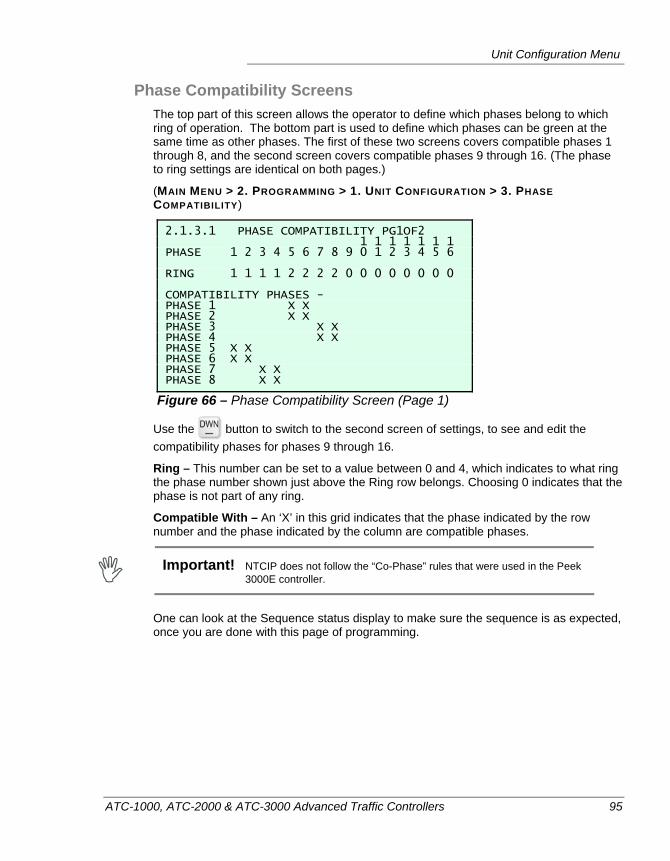
Unit Configuration Menu
ATC-1000, ATC-2000 & ATC-3000 Advanced Traffic Controllers 95
Phase Compatibility Screens The top part of this screen allows the operator to define which phases belong to which ring of operation. The bottom part is used to define which phases can be green at the same time as other phases. The first of these two screens covers compatible phases 1 through 8, and the second screen covers compatible phases 9 through 16. (The phase to ring settings are identical on both pages.)
(MAIN MENU > 2. PROGRAMMING > 1. UNIT CONFIGURATION > 3. PHASE COMPATIBILITY)
2.1.3.1 PHASE COMPATIBILITY PG1OF2 1 1 1 1 1 1 1 PHASE 1 2 3 4 5 6 7 8 9 0 1 2 3 4 5 6 RING 1 1 1 1 2 2 2 2 0 0 0 0 0 0 0 0 COMPATIBILITY PHASES - PHASE 1 X X PHASE 2 X X PHASE 3 X X PHASE 4 X X PHASE 5 X X PHASE 6 X X PHASE 7 X X PHASE 8 X X
Figure 66 – Phase Compatibility Screen (Page 1)
Use the button to switch to the second screen of settings, to see and edit the compatibility phases for phases 9 through 16.
Ring – This number can be set to a value between 0 and 4, which indicates to what ring the phase number shown just above the Ring row belongs. Choosing 0 indicates that the phase is not part of any ring.
Compatible With – An ‘X’ in this grid indicates that the phase indicated by the row number and the phase indicated by the column are compatible phases.
Important! NTCIP does not follow the “Co-Phase” rules that were used in the Peek
3000E controller.
One can look at the Sequence status display to make sure the sequence is as expected, once you are done with this page of programming.
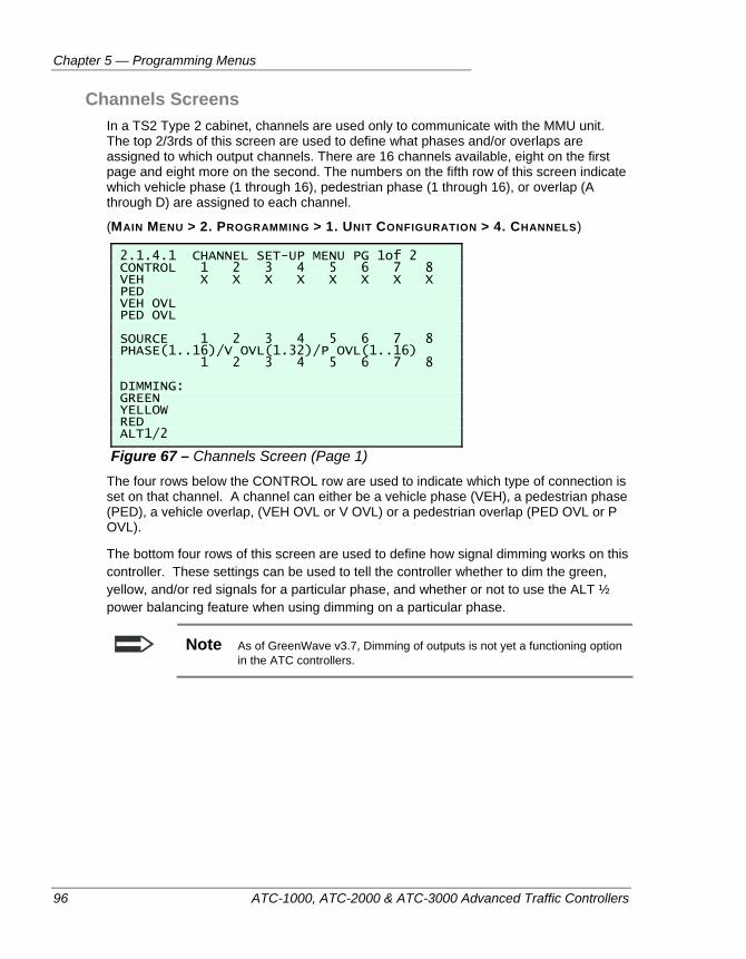
Chapter 5 — Programming Menus
96 ATC-1000, ATC-2000 & ATC-3000 Advanced Traffic Controllers
Channels Screens In a TS2 Type 2 cabinet, channels are used only to communicate with the MMU unit. The top 2/3rds of this screen are used to define what phases and/or overlaps are assigned to which output channels. There are 16 channels available, eight on the first page and eight more on the second. The numbers on the fifth row of this screen indicate which vehicle phase (1 through 16), pedestrian phase (1 through 16), or overlap (A through D) are assigned to each channel.
(MAIN MENU > 2. PROGRAMMING > 1. UNIT CONFIGURATION > 4. CHANNELS)
2.1.4.1 CHANNEL SET-UP MENU PG 1of 2 CONTROL 1 2 3 4 5 6 7 8 VEH X X X X X X X X PED VEH OVL PED OVL SOURCE 1 2 3 4 5 6 7 8 PHASE(1..16)/V OVL(1.32)/P OVL(1..16) 1 2 3 4 5 6 7 8 DIMMING: GREEN YELLOW RED ALT1/2
Figure 67 – Channels Screen (Page 1) The four rows below the CONTROL row are used to indicate which type of connection is set on that channel. A channel can either be a vehicle phase (VEH), a pedestrian phase (PED), a vehicle overlap, (VEH OVL or V OVL) or a pedestrian overlap (PED OVL or P OVL).
The bottom four rows of this screen are used to define how signal dimming works on this controller. These settings can be used to tell the controller whether to dim the green, yellow, and/or red signals for a particular phase, and whether or not to use the ALT ½ power balancing feature when using dimming on a particular phase.
Note As of GreenWave v3.7, Dimming of outputs is not yet a functioning option in the ATC controllers.
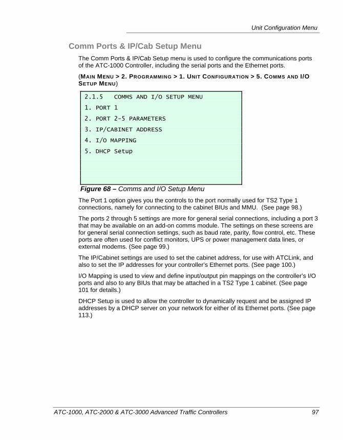
Unit Configuration Menu
ATC-1000, ATC-2000 & ATC-3000 Advanced Traffic Controllers 97
Comm Ports & IP/Cab Setup Menu The Comm Ports & IP/Cab Setup menu is used to configure the communications ports of the ATC-1000 Controller, including the serial ports and the Ethernet ports.
(MAIN MENU > 2. PROGRAMMING > 1. UNIT CONFIGURATION > 5. COMMS AND I/O SETUP MENU)
2.1.5 COMMS AND I/O SETUP MENU 1. PORT 1 2. PORT 2-5 PARAMETERS 3. IP/CABINET ADDRESS 4. I/O MAPPING 5. DHCP Setup
Figure 68 – Comms and I/O Setup Menu The Port 1 option gives you the controls to the port normally used for TS2 Type 1 connections, namely for connecting to the cabinet BIUs and MMU. (See page 98.)
The ports 2 through 5 settings are more for general serial connections, including a port 3 that may be available on an add-on comms module. The settings on these screens are for general serial connection settings, such as baud rate, parity, flow control, etc. These ports are often used for conflict monitors, UPS or power management data lines, or external modems. (See page 99.)
The IP/Cabinet settings are used to set the cabinet address, for use with ATCLink, and also to set the IP addresses for your controller’s Ethernet ports. (See page 100.)
I/O Mapping is used to view and define input/output pin mappings on the controller’s I/O ports and also to any BIUs that may be attached in a TS2 Type 1 cabinet. (See page 101 for details.)
DHCP Setup is used to allow the controller to dynamically request and be assigned IP addresses by a DHCP server on your network for either of its Ethernet ports. (See page 113.)
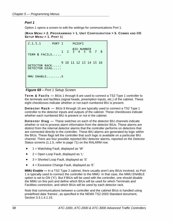
Chapter 5 — Programming Menus
98 ATC-1000, ATC-2000 & ATC-3000 Advanced Traffic Controllers
Port 1 Option 1 opens a screen to edit the settings for communications Port 1.
(MAIN MENU > 2. PROGRAMMING > 1. UNIT CONFIGURATION > 5. COMMS AND I/O SETUP MENU > 1. PORT 1)
2.1.5.1 PORT 1 PG1OF1 BIU NUMBER 1 2 3 4 5 6 7 8 TERM & FACILS..... 9 10 11 12 13 14 15 16 DETECTOR RACK..... DETECTOR DIAG..... MMU ENABLE........X
Figure 69 – Port 1 Setup Screen Term & Faci ls — BIUs 1 through 8 are used to connect a TS2 Type 1 controller to the terminals and facilities (signal heads, preemption inputs, etc.) of the cabinet. These eight checkboxes indicate whether or not each numbered BIU is present.
Detector Rack — BIUs 9 through 16 are typically used to connect a TS2 Type 1 controller to the detector inputs and outputs of the cabinet. These checkboxes indicate whether each numbered BIU is present or not in the cabinet.
Detector Diag — These switches on each of the detector BIU channels indicate whether or not to process alarm information from the detector BIUs. These alarms are distinct from the internal detector alarms that the controller performs on detectors that are connected directly to the controller. These BIU alarms are generated by logic within the BIUs. These flags tell the controller that such logic is available on a particular BIU channel. There are four possible reported BIU detector alarms, reported on the Detector Status screens (1.1.5, refer to page 71) on the RALARM row:
1 = Watchdog Fault, displayed as ‘W’
2 = Open Loop Fault, displayed as ‘L’
3 = Shorted Loop Fault, displayed as ‘S’
4 = Excessive Change Fault, displayed as ‘E’
MMU Enable — In a TS2 Type 2 cabinet, there usually aren’t any BIUs involved, so Port 1 is typically used to connect the controller to the MMU. In that case, the MMU ENABLE option is set to ON (‘X’). But if BIUs will be used with the controller, one should disable the MMU on this port and define which BIUs will be used for which Terminals and Facilities connection, and which BIUs will be used by each detector rack.
Note that communications between a controller and the cabinet BIUs is handled using predefined data ‘frames’, as specified in the NEMA TS2-2003 Standard document, Section 3.3.1.4.1.15.
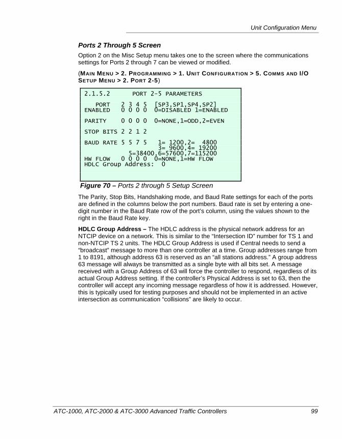
Unit Configuration Menu
ATC-1000, ATC-2000 & ATC-3000 Advanced Traffic Controllers 99
Ports 2 Through 5 Screen Option 2 on the Misc Setup menu takes one to the screen where the communications settings for Ports 2 through 7 can be viewed or modified.
(MAIN MENU > 2. PROGRAMMING > 1. UNIT CONFIGURATION > 5. COMMS AND I/O SETUP MENU > 2. PORT 2-5)
2.1.5.2 PORT 2-5 PARAMETERS PORT 2 3 4 5 [SP3,SP1,SP4,SP2] ENABLED 0 0 0 0 0=DISABLED 1=ENABLED PARITY 0 0 0 0 0=NONE,1=ODD,2=EVEN STOP BITS 2 2 1 2 BAUD RATE 5 5 7 5 1= 1200,2= 4800 3= 9600,4= 19200 5=38400,6=57600,7=115200 HW FLOW 0 0 0 0 0=NONE,1=HW FLOW HDLC Group Address: 0
Figure 70 – Ports 2 through 5 Setup Screen The Parity, Stop Bits, Handshaking mode, and Baud Rate settings for each of the ports are defined in the columns below the port numbers. Baud rate is set by entering a one-digit number in the Baud Rate row of the port’s column, using the values shown to the right in the Baud Rate key.
HDLC Group Address – The HDLC address is the physical network address for an NTCIP device on a network. This is similar to the “Intersection ID” number for TS 1 and non-NTCIP TS 2 units. The HDLC Group Address is used if Central needs to send a “broadcast” message to more than one controller at a time. Group addresses range from 1 to 8191, although address 63 is reserved as an “all stations address.” A group address 63 message will always be transmitted as a single byte with all bits set. A message received with a Group Address of 63 will force the controller to respond, regardless of its actual Group Address setting. If the controller’s Physical Address is set to 63, then the controller will accept any incoming message regardless of how it is addressed. However, this is typically used for testing purposes and should not be implemented in an active intersection as communication “collisions” are likely to occur.
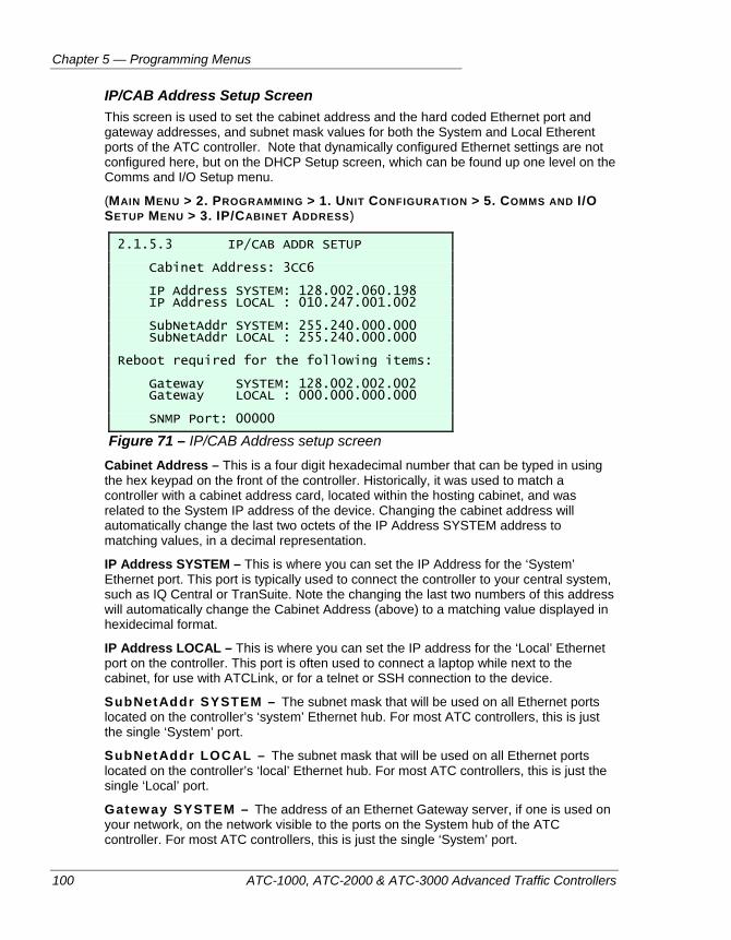
Chapter 5 — Programming Menus
100 ATC-1000, ATC-2000 & ATC-3000 Advanced Traffic Controllers
IP/CAB Address Setup Screen This screen is used to set the cabinet address and the hard coded Ethernet port and gateway addresses, and subnet mask values for both the System and Local Etherent ports of the ATC controller. Note that dynamically configured Ethernet settings are not configured here, but on the DHCP Setup screen, which can be found up one level on the Comms and I/O Setup menu.
(MAIN MENU > 2. PROGRAMMING > 1. UNIT CONFIGURATION > 5. COMMS AND I/O SETUP MENU > 3. IP/CABINET ADDRESS)
2.1.5.3 IP/CAB ADDR SETUP Cabinet Address: 3CC6 IP Address SYSTEM: 128.002.060.198 IP Address LOCAL : 010.247.001.002 SubNetAddr SYSTEM: 255.240.000.000 SubNetAddr LOCAL : 255.240.000.000 Reboot required for the following items: Gateway SYSTEM: 128.002.002.002 Gateway LOCAL : 000.000.000.000 SNMP Port: 00000
Figure 71 – IP/CAB Address setup screen Cabinet Address – This is a four digit hexadecimal number that can be typed in using the hex keypad on the front of the controller. Historically, it was used to match a controller with a cabinet address card, located within the hosting cabinet, and was related to the System IP address of the device. Changing the cabinet address will automatically change the last two octets of the IP Address SYSTEM address to matching values, in a decimal representation.
IP Address SYSTEM – This is where you can set the IP Address for the ‘System’ Ethernet port. This port is typically used to connect the controller to your central system, such as IQ Central or TranSuite. Note the changing the last two numbers of this address will automatically change the Cabinet Address (above) to a matching value displayed in hexidecimal format.
IP Address LOCAL – This is where you can set the IP address for the ‘Local’ Ethernet port on the controller. This port is often used to connect a laptop while next to the cabinet, for use with ATCLink, or for a telnet or SSH connection to the device.
SubNetAddr SYSTEM – The subnet mask that will be used on all Ethernet ports located on the controller’s ‘system’ Ethernet hub. For most ATC controllers, this is just the single ‘System’ port.
SubNetAddr LOCAL – The subnet mask that will be used on all Ethernet ports located on the controller’s ‘local’ Ethernet hub. For most ATC controllers, this is just the single ‘Local’ port.
Gateway SYSTEM – The address of an Ethernet Gateway server, if one is used on your network, on the network visible to the ports on the System hub of the ATC controller. For most ATC controllers, this is just the single ‘System’ port.
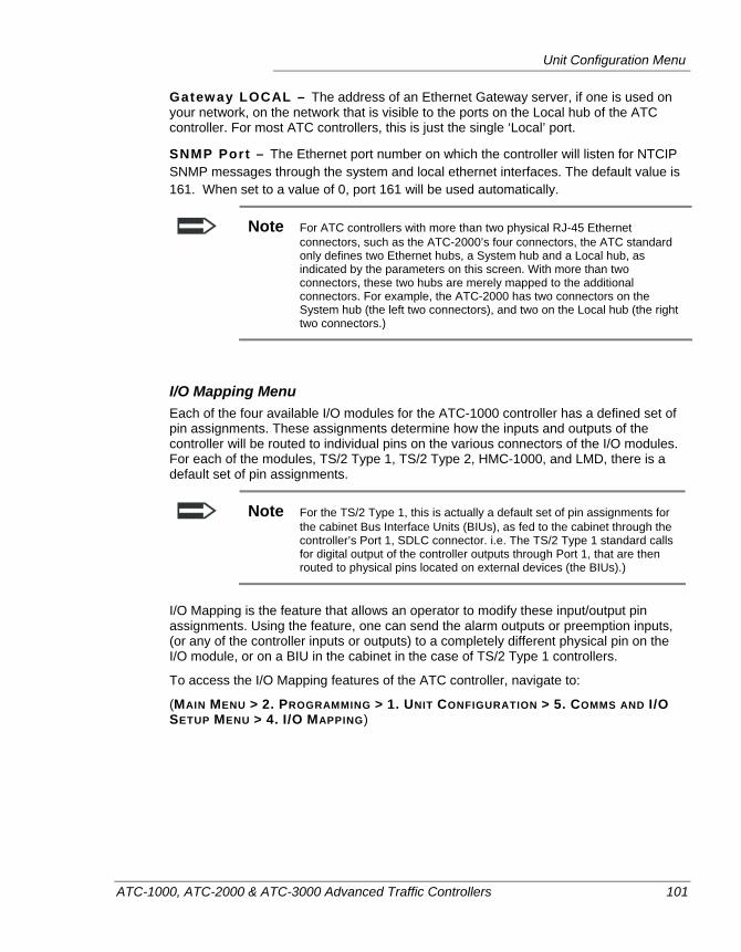
Unit Configuration Menu
ATC-1000, ATC-2000 & ATC-3000 Advanced Traffic Controllers 101
Gateway LOCAL – The address of an Ethernet Gateway server, if one is used on your network, on the network that is visible to the ports on the Local hub of the ATC controller. For most ATC controllers, this is just the single ‘Local’ port.
SNMP Port – The Ethernet port number on which the controller will listen for NTCIP SNMP messages through the system and local ethernet interfaces. The default value is 161. When set to a value of 0, port 161 will be used automatically.
Note For ATC controllers with more than two physical RJ-45 Ethernet connectors, such as the ATC-2000’s four connectors, the ATC standard only defines two Ethernet hubs, a System hub and a Local hub, as indicated by the parameters on this screen. With more than two connectors, these two hubs are merely mapped to the additional connectors. For example, the ATC-2000 has two connectors on the System hub (the left two connectors), and two on the Local hub (the right two connectors.)
I/O Mapping Menu Each of the four available I/O modules for the ATC-1000 controller has a defined set of pin assignments. These assignments determine how the inputs and outputs of the controller will be routed to individual pins on the various connectors of the I/O modules. For each of the modules, TS/2 Type 1, TS/2 Type 2, HMC-1000, and LMD, there is a default set of pin assignments.
Note For the TS/2 Type 1, this is actually a default set of pin assignments for the cabinet Bus Interface Units (BIUs), as fed to the cabinet through the controller’s Port 1, SDLC connector. i.e. The TS/2 Type 1 standard calls for digital output of the controller outputs through Port 1, that are then routed to physical pins located on external devices (the BIUs).)
I/O Mapping is the feature that allows an operator to modify these input/output pin assignments. Using the feature, one can send the alarm outputs or preemption inputs, (or any of the controller inputs or outputs) to a completely different physical pin on the I/O module, or on a BIU in the cabinet in the case of TS/2 Type 1 controllers.
To access the I/O Mapping features of the ATC controller, navigate to:
(MAIN MENU > 2. PROGRAMMING > 1. UNIT CONFIGURATION > 5. COMMS AND I/O SETUP MENU > 4. I/O MAPPING)
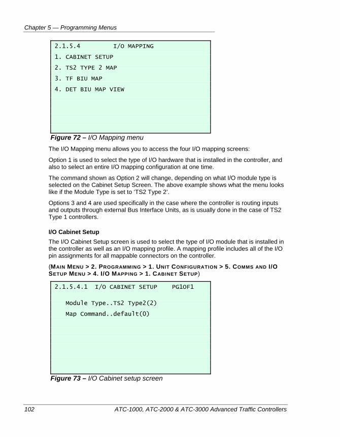
Chapter 5 — Programming Menus
102 ATC-1000, ATC-2000 & ATC-3000 Advanced Traffic Controllers
2.1.5.4 I/O MAPPING 1. CABINET SETUP 2. TS2 TYPE 2 MAP 3. TF BIU MAP 4. DET BIU MAP VIEW
Figure 72 – I/O Mapping menu The I/O Mapping menu allows you to access the four I/O mapping screens:
Option 1 is used to select the type of I/O hardware that is installed in the controller, and also to select an entire I/O mapping configuration at one time.
The command shown as Option 2 will change, depending on what I/O module type is selected on the Cabinet Setup Screen. The above example shows what the menu looks like if the Module Type is set to ‘TS2 Type 2’.
Options 3 and 4 are used specifically in the case where the controller is routing inputs and outputs through external Bus Interface Units, as is usually done in the case of TS2 Type 1 controllers.
I/O Cabinet Setup The I/O Cabinet Setup screen is used to select the type of I/O module that is installed in the controller as well as an I/O mapping profile. A mapping profile includes all of the I/O pin assignments for all mappable connectors on the controller.
(MAIN MENU > 2. PROGRAMMING > 1. UNIT CONFIGURATION > 5. COMMS AND I/O SETUP MENU > 4. I/O MAPPING > 1. CABINET SETUP)
2.1.5.4.1 I/O CABINET SETUP PG1OF1 Module Type..TS2 Type2(2) Map Command..default(0)
Figure 73 – I/O Cabinet setup screen
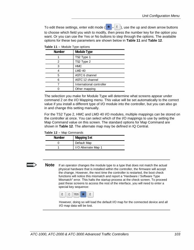
Unit Configuration Menu
ATC-1000, ATC-2000 & ATC-3000 Advanced Traffic Controllers 103
To edit these settings, enter edit mode ( - ), use the up and down arrow buttons to choose which field you wish to modify, then press the number key for the option you want. Or you can use the Yes or No buttons to step through the options. The available options for these two parameters are shown below in Table 11 and Table 12.
Table 11 – Module Type options
Number Module Type 1 TS2 Type 1 2 TS2 Type 2 3 HMC 4 LMD 40 5 ASTC 6 channel 6 ASTC 12 channel 7 International controller 0 Other mapping
The selection you make for Module Type will determine what screens appear under command 2 on the I/O Mapping menu. This value will be set automatically to the correct value if you install a different type of I/O module into the controller, but you can also go in and change this setting manually.
For the TS2 Type 2, HMC and LMD 40 I/O modules, multiple mappings can be stored on the controller at once. You can select which of the I/O mappings to use by setting the Map Command value on this screen. The standard options for Map Command are shown in Table 12. The alternate map may be defined in IQ Central.
Table 12 – Map Commands
Number Mapping Set 0 Default Map 1 I/O Alternate Map 1
Note If an operator changes the module type to a type that does not match the actual physical hardware that is installed within the controller, the firmware will accept the change. However, the next time the controller is restarted, the boot check functions will notice this mismatch and report a “Hardware / Software Type Mismatch” error. This halts the startup process at the check screen. To proceed past these screens to access the rest of the interface, you will need to enter a special key sequence:
However, doing so will load the default I/O map for the connected device and all I/O map data will be lost.
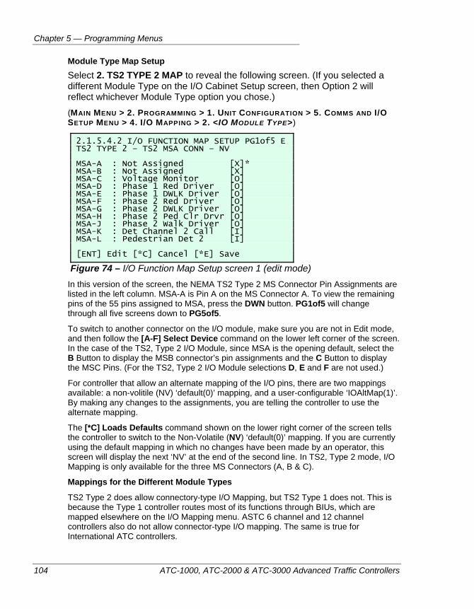
Chapter 5 — Programming Menus
104 ATC-1000, ATC-2000 & ATC-3000 Advanced Traffic Controllers
Module Type Map Setup Select 2. TS2 TYPE 2 MAP to reveal the following screen. (If you selected a different Module Type on the I/O Cabinet Setup screen, then Option 2 will reflect whichever Module Type option you chose.) (MAIN MENU > 2. PROGRAMMING > 1. UNIT CONFIGURATION > 5. COMMS AND I/O SETUP MENU > 4. I/O MAPPING > 2. <IO MODULE TYPE>)
2.1.5.4.2 I/O FUNCTION MAP SETUP PG1of5 E TS2 TYPE 2 – TS2 MSA CONN – NV MSA-A : Not Assigned [X]* MSA-B : Not Assigned [X] MSA-C : Voltage Monitor [O] MSA-D : Phase 1 Red Driver [O] MSA-E : Phase 1 DWLK Driver [O] MSA-F : Phase 2 Red Driver [O] MSA-G : Phase 2 DWLK Driver [O] MSA-H : Phase 2 Ped Clr Drvr [O] MSA-J : Phase 2 Walk Driver [O] MSA-K : Det Channel 2 Call [I] MSA-L : Pedestrian Det 2 [I] [ENT] Edit [*C] Cancel [*E] Save
Figure 74 – I/O Function Map Setup screen 1 (edit mode) In this version of the screen, the NEMA TS2 Type 2 MS Connector Pin Assignments are listed in the left column. MSA-A is Pin A on the MS Connector A. To view the remaining pins of the 55 pins assigned to MSA, press the DWN button. PG1of5 will change through all five screens down to PG5of5.
To switch to another connector on the I/O module, make sure you are not in Edit mode, and then follow the [A-F] Select Device command on the lower left corner of the screen. In the case of the TS2, Type 2 I/O Module, since MSA is the opening default, select the B Button to display the MSB connector’s pin assignments and the C Button to display the MSC Pins. (For the TS2, Type 2 I/O Module selections D, E and F are not used.)
For controller that allow an alternate mapping of the I/O pins, there are two mappings available: a non-volitile (NV) ‘default(0)’ mapping, and a user-configurable ‘IOAltMap(1)’. By making any changes to the assignments, you are telling the controller to use the alternate mapping.
The [*C] Loads Defaults command shown on the lower right corner of the screen tells the controller to switch to the Non-Volatile (NV) ‘default(0)’ mapping. If you are currently using the default mapping in which no changes have been made by an operator, this screen will display the next ‘NV’ at the end of the second line. In TS2, Type 2 mode, I/O Mapping is only available for the three MS Connectors (A, B & C).
Mappings for the Different Module Types
TS2 Type 2 does allow connectory-type I/O Mapping, but TS2 Type 1 does not. This is because the Type 1 controller routes most of its functions through BIUs, which are mapped elsewhere on the I/O Mapping menu. ASTC 6 channel and 12 channel controllers also do not allow connector-type I/O mapping. The same is true for International ATC controllers.
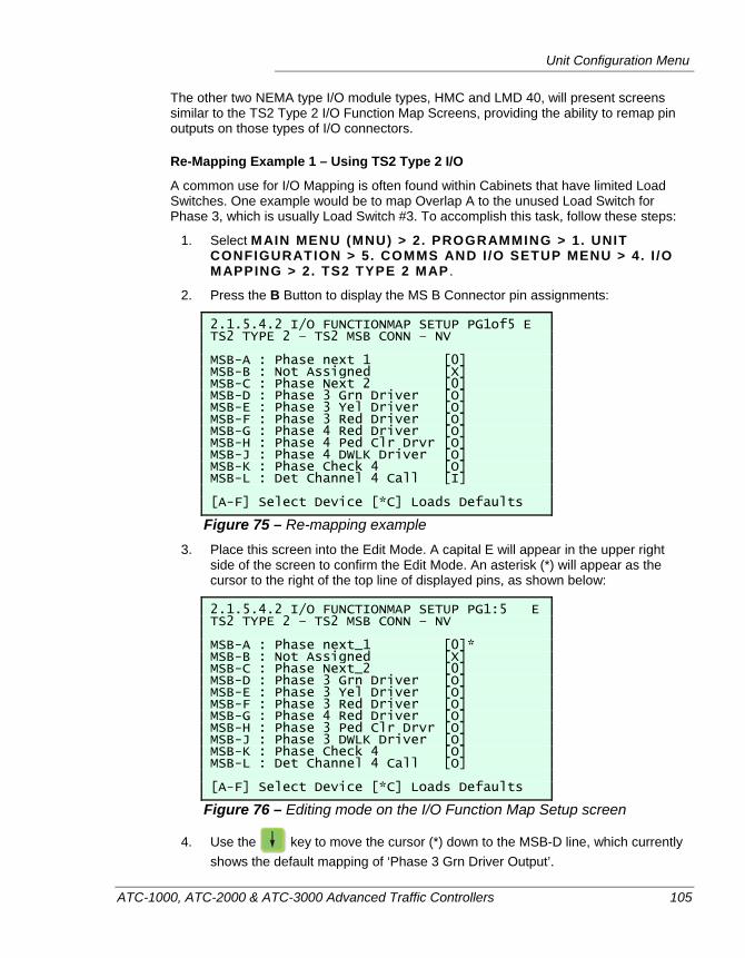
Unit Configuration Menu
ATC-1000, ATC-2000 & ATC-3000 Advanced Traffic Controllers 105
The other two NEMA type I/O module types, HMC and LMD 40, will present screens similar to the TS2 Type 2 I/O Function Map Screens, providing the ability to remap pin outputs on those types of I/O connectors.
Re-Mapping Example 1 – Using TS2 Type 2 I/O
A common use for I/O Mapping is often found within Cabinets that have limited Load Switches. One example would be to map Overlap A to the unused Load Switch for Phase 3, which is usually Load Switch #3. To accomplish this task, follow these steps:
1. Select MAIN MENU (MNU) > 2. PROGRAMMING > 1. UNIT CONFIGURATION > 5. COMMS AND I /O SETUP MENU > 4. I /O MAPPING > 2. TS2 TYPE 2 MAP .
2. Press the B Button to display the MS B Connector pin assignments:
2.1.5.4.2 I/O FUNCTIONMAP SETUP PG1of5 E TS2 TYPE 2 – TS2 MSB CONN – NV MSB-A : Phase next 1 [0] MSB-B : Not Assigned [X] MSB-C : Phase Next 2 [0] MSB-D : Phase 3 Grn Driver [O] MSB-E : Phase 3 Yel Driver [O] MSB-F : Phase 3 Red Driver [O] MSB-G : Phase 4 Red Driver [O] MSB-H : Phase 4 Ped Clr Drvr [O] MSB-J : Phase 4 DWLK Driver [O] MSB-K : Phase Check 4 [O] MSB-L : Det Channel 4 Call [I] [A-F] Select Device [*C] Loads Defaults
Figure 75 – Re-mapping example 3. Place this screen into the Edit Mode. A capital E will appear in the upper right
side of the screen to confirm the Edit Mode. An asterisk (*) will appear as the cursor to the right of the top line of displayed pins, as shown below:
2.1.5.4.2 I/O FUNCTIONMAP SETUP PG1:5 E TS2 TYPE 2 – TS2 MSB CONN – NV MSB-A : Phase next_1 [0]* MSB-B : Not Assigned [X] MSB-C : Phase Next_2 [0] MSB-D : Phase 3 Grn Driver [O] MSB-E : Phase 3 Yel Driver [O] MSB-F : Phase 3 Red Driver [O] MSB-G : Phase 4 Red Driver [O] MSB-H : Phase 3 Ped Clr Drvr [O] MSB-J : Phase 3 DWLK Driver [O] MSB-K : Phase Check 4 [O] MSB-L : Det Channel 4 Call [O] [A-F] Select Device [*C] Loads Defaults
Figure 76 – Editing mode on the I/O Function Map Setup screen
4. Use the key to move the cursor (*) down to the MSB-D line, which currently shows the default mapping of ‘Phase 3 Grn Driver Output’.
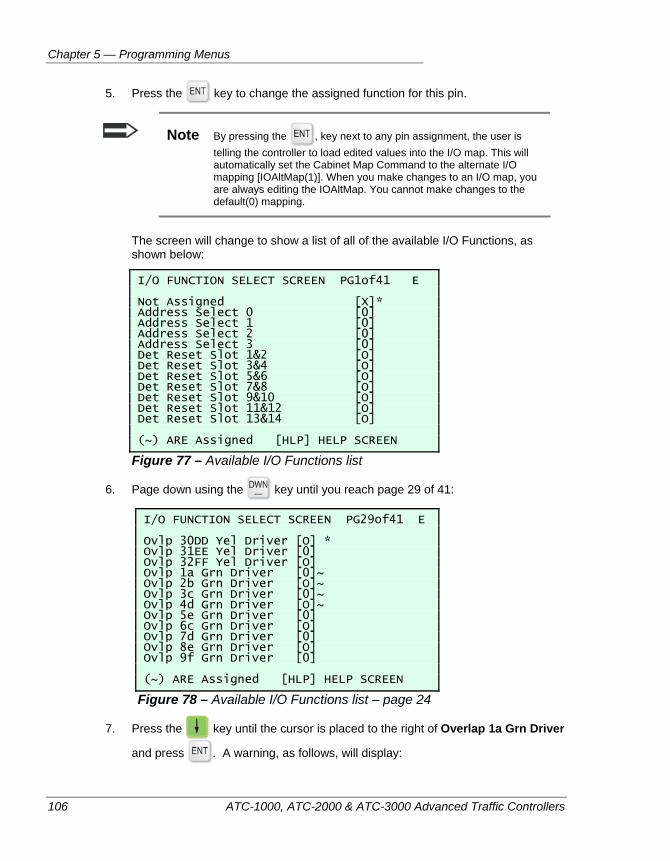
Chapter 5 — Programming Menus
106 ATC-1000, ATC-2000 & ATC-3000 Advanced Traffic Controllers
5. Press the key to change the assigned function for this pin.
Note By pressing the , key next to any pin assignment, the user is telling the controller to load edited values into the I/O map. This will automatically set the Cabinet Map Command to the alternate I/O mapping [IOAltMap(1)]. When you make changes to an I/O map, you are always editing the IOAltMap. You cannot make changes to the default(0) mapping.
The screen will change to show a list of all of the available I/O Functions, as shown below:
I/O FUNCTION SELECT SCREEN PG1of41 E Not Assigned [X]* Address Select 0 [0] Address Select 1 [0] Address Select 2 [0] Address Select 3 [0] Det Reset Slot 1&2 [O] Det Reset Slot 3&4 [O] Det Reset Slot 5&6 [O] Det Reset Slot 7&8 [O] Det Reset Slot 9&10 [O] Det Reset Slot 11&12 [O] Det Reset Slot 13&14 [O] (~) ARE Assigned [HLP] HELP SCREEN
Figure 77 – Available I/O Functions list
6. Page down using the key until you reach page 29 of 41:
I/O FUNCTION SELECT SCREEN PG29of41 E Ovlp 30DD Yel Driver [O] * Ovlp 31EE Yel Driver [0] Ovlp 32FF Yel Driver [O] Ovlp 1a Grn Driver [0]~ Ovlp 2b Grn Driver [O]~ Ovlp 3c Grn Driver [0]~ Ovlp 4d Grn Driver [O]~ Ovlp 5e Grn Driver [0] Ovlp 6c Grn Driver [O] Ovlp 7d Grn Driver [0] Ovlp 8e Grn Driver [O] Ovlp 9f Grn Driver [0] (~) ARE Assigned [HLP] HELP SCREEN
Figure 78 – Available I/O Functions list – page 24
7. Press the key until the cursor is placed to the right of Overlap 1a Grn Driver
and press . A warning, as follows, will display:
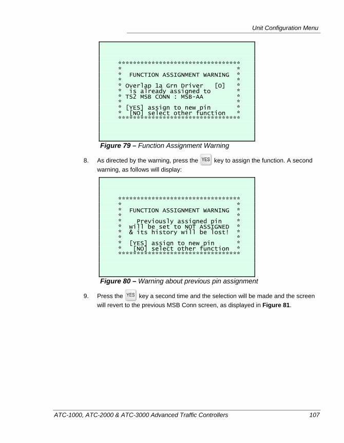
Unit Configuration Menu
ATC-1000, ATC-2000 & ATC-3000 Advanced Traffic Controllers 107
********************************* * * * FUNCTION ASSIGNMENT WARNING * * * * Overlap 1a Grn Driver [O] * * is already assigned to * * TS2 MSB CONN : MSB-AA * * * * [YES] assign to new pin * * [NO] select other function * *********************************
Figure 79 – Function Assignment Warning
8. As directed by the warning, press the key to assign the function. A second warning, as follows will display:
********************************* * * * FUNCTION ASSIGNMENT WARNING * * * * Previously assigned pin * * will be set to NOT ASSIGNED * * & its history will be lost! * * * * [YES] assign to new pin * * [NO] select other function * *********************************
Figure 80 – Warning about previous pin assignment
9. Press the key a second time and the selection will be made and the screen will revert to the previous MSB Conn screen, as displayed in Figure 81.
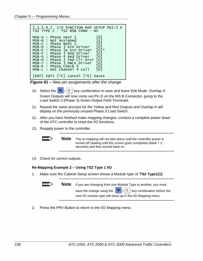
Chapter 5 — Programming Menus
108 ATC-1000, ATC-2000 & ATC-3000 Advanced Traffic Controllers
2.1.5.4.2 I/O FUNCTION MAP SETUP PG1:5 E TS2 TYPE 2 – TS2 MSB CONN – NV MSB-A : Phase next 1 [0] MSB-B : Not Assigned [X] MSB-C : Phase Next 2 [0] MSB-D : Phase 3 Grn Driver [O] MSB-E : Phase 1a Grn Driver [O]* MSB-F : Phase 3 Red Driver [O] MSB-G : Phase 4 Red Driver [O] MSB-H : Phase 3 Ped Clr Drvr [O] MSB-J : Phase 3 DWLK Driver [O] MSB-K : Phase Check 4 [O] MSB-L : Det Channel 4 Call [O] [ENT] Edit [*C] Cancel [*E] Saves
Figure 81 – New pin assignments after the change
10. Select the - key combination to save and leave Edit Mode. Overlap A Green Outputs will now come out Pin D on the MS B Connector, going to the Load Switch 3 (Phase 3) Green Output Field Terminals.
11. Repeat the same process for the Yellow and Red Outputs and Overlap A will display on the previously unused Phase 3 Load Switch.
12. After you have finished make mapping changes, conduct a complete power down of the ATC controller to reset the I/O functions.
13. Reapply power to the controller.
Note The re-mapping will not take place until the controller power is turned off (waiting until the screen goes completely blank + 2 seconds) and then turned back on.
14. Check for correct outputs.
Re-Mapping Example 2 – Using TS2 Type 1 I/O
1. Make sure the Cabinet Setup screen shows a Module type of ‘TS2 Type1(1)’.
Note If you are changing from one Module Type to another, you must
save the change using the - key combination before the new I/O module type will show up in the I/O Mapping menu.
2. Press the PRV Button to return to the I/O Mapping menu.
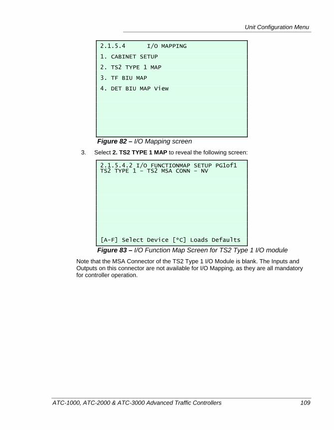
Unit Configuration Menu
ATC-1000, ATC-2000 & ATC-3000 Advanced Traffic Controllers 109
2.1.5.4 I/O MAPPING 1. CABINET SETUP 2. TS2 TYPE 1 MAP 3. TF BIU MAP 4. DET BIU MAP View
Figure 82 – I/O Mapping screen 3. Select 2. TS2 TYPE 1 MAP to reveal the following screen:
2.1.5.4.2 I/O FUNCTIONMAP SETUP PG1of1 TS2 TYPE 1 – TS2 MSA CONN – NV [A-F] Select Device [*C] Loads Defaults
Figure 83 – I/O Function Map Screen for TS2 Type 1 I/O module Note that the MSA Connector of the TS2 Type 1 I/O Module is blank. The Inputs and Outputs on this connector are not available for I/O Mapping, as they are all mandatory for controller operation.
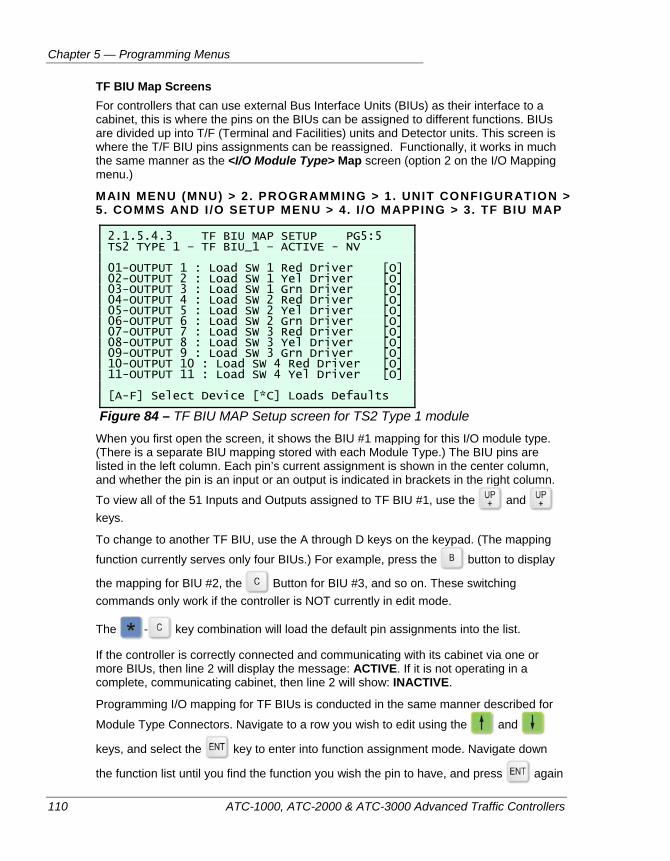
Chapter 5 — Programming Menus
110 ATC-1000, ATC-2000 & ATC-3000 Advanced Traffic Controllers
TF BIU Map Screens For controllers that can use external Bus Interface Units (BIUs) as their interface to a cabinet, this is where the pins on the BIUs can be assigned to different functions. BIUs are divided up into T/F (Terminal and Facilities) units and Detector units. This screen is where the T/F BIU pins assignments can be reassigned. Functionally, it works in much the same manner as the <I/O Module Type> Map screen (option 2 on the I/O Mapping menu.)
MAIN MENU (MNU) > 2 . PROGRAMMING > 1. UNIT CONFIGURATION > 5 . COMMS AND I /O SETUP MENU > 4. I /O MAPPING > 3. TF BIU MAP
2.1.5.4.3 TF BIU MAP SETUP PG5:5 TS2 TYPE 1 – TF BIU_1 – ACTIVE - NV 01-OUTPUT 1 : Load SW 1 Red Driver [O] 02-OUTPUT 2 : Load SW 1 Yel Driver [O] 03-OUTPUT 3 : Load SW 1 Grn Driver [O] 04-OUTPUT 4 : Load SW 2 Red Driver [O] 05-OUTPUT 5 : Load SW 2 Yel Driver [O] 06-OUTPUT 6 : Load SW 2 Grn Driver [O] 07-OUTPUT 7 : Load SW 3 Red Driver [O] 08-OUTPUT 8 : Load SW 3 Yel Driver [O] 09-OUTPUT 9 : Load SW 3 Grn Driver [O] 10-OUTPUT 10 : Load SW 4 Red Driver [O] 11-OUTPUT 11 : Load SW 4 Yel Driver [O] [A-F] Select Device [*C] Loads Defaults
Figure 84 – TF BIU MAP Setup screen for TS2 Type 1 module When you first open the screen, it shows the BIU #1 mapping for this I/O module type. (There is a separate BIU mapping stored with each Module Type.) The BIU pins are listed in the left column. Each pin’s current assignment is shown in the center column, and whether the pin is an input or an output is indicated in brackets in the right column.
To view all of the 51 Inputs and Outputs assigned to TF BIU #1, use the and keys.
To change to another TF BIU, use the A through D keys on the keypad. (The mapping function currently serves only four BIUs.) For example, press the button to display
the mapping for BIU #2, the Button for BIU #3, and so on. These switching commands only work if the controller is NOT currently in edit mode.
The - key combination will load the default pin assignments into the list.
If the controller is correctly connected and communicating with its cabinet via one or more BIUs, then line 2 will display the message: ACTIVE. If it is not operating in a complete, communicating cabinet, then line 2 will show: INACTIVE.
Programming I/O mapping for TF BIUs is conducted in the same manner described for
Module Type Connectors. Navigate to a row you wish to edit using the and
keys, and select the key to enter into function assignment mode. Navigate down
the function list until you find the function you wish the pin to have, and press again
Unit Configuration Menu
ATC-1000, ATC-2000 & ATC-3000 Advanced Traffic Controllers 111
to make the assignment. If the function is already assigned on another pin, you will be
prompted for a to continue. You will be prompted again to approve the removal of the other assignment.
Some additional hints about BIU function assignment:
Accepting the edit values in I/O Mapping for TF BIUs will automatically set that TF BIU to be ACTIVE after cycling power.
TF BIUs selected to I/O Mapping functions supersede all other device functions during initial power up.
Selecting a TF BIU to set duplicate function(s) on another BIU will result in the function that was duplicated to be set to “Not Assigned”.
If a TF BIU is already active and a function is selected on another BIU that is a duplicate on the active BIU, then the last programmed BIU will take precedence and set the previously active BIU function to “Not Assigned.”
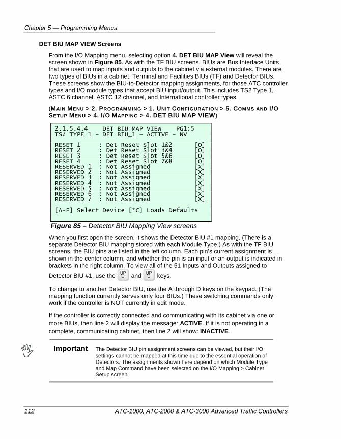
Chapter 5 — Programming Menus
112 ATC-1000, ATC-2000 & ATC-3000 Advanced Traffic Controllers
DET BIU MAP VIEW Screens
From the I/O Mapping menu, selecting option 4. DET BIU MAP View will reveal the screen shown in Figure 85. As with the TF BIU screens, BIUs are Bus Interface Units that are used to map inputs and outputs to the cabinet via external modules. There are two types of BIUs in a cabinet, Terminal and Facilities BIUs (TF) and Detector BIUs. These screens show the BIU-to-Detector mapping assignments, for those ATC controller types and I/O module types that accept BIU input/output. This includes TS2 Type 1, ASTC 6 channel, ASTC 12 channel, and International controller types.
(MAIN MENU > 2. PROGRAMMING > 1. UNIT CONFIGURATION > 5. COMMS AND I/O SETUP MENU > 4. I/O MAPPING > 4. DET BIU MAP VIEW)
2.1.5.4.4 DET BIU MAP VIEW PG1:5 TS2 TYPE 1 – DET BIU_1 – ACTIVE - NV RESET 1 : Det Reset Slot 1&2 [O] RESET 2 : Det Reset Slot 3&4 [O] RESET 3 : Det Reset Slot 5&6 [O] RESET 4 : Det Reset Slot 7&8 [O] RESERVED 1 : Not Assigned [X] RESERVED 2 : Not Assigned [X] RESERVED 3 : Not Assigned [X] RESERVED 4 : Not Assigned [X] RESERVED 5 : Not Assigned [X] RESERVED 6 : Not Assigned [X] RESERVED 7 : Not Assigned [X] [A-F] Select Device [*C] Loads Defaults
Figure 85 – Detector BIU Mapping View screens When you first open the screen, it shows the Detector BIU #1 mapping. (There is a separate Detector BIU mapping stored with each Module Type.) As with the TF BIU screens, the BIU pins are listed in the left column. Each pin’s current assignment is shown in the center column, and whether the pin is an input or an output is indicated in brackets in the right column. To view all of the 51 Inputs and Outputs assigned to
Detector BIU #1, use the and keys.
To change to another Detector BIU, use the A through D keys on the keypad. (The mapping function currently serves only four BIUs.) These switching commands only work if the controller is NOT currently in edit mode.
If the controller is correctly connected and communicating with its cabinet via one or more BIUs, then line 2 will display the message: ACTIVE. If it is not operating in a complete, communicating cabinet, then line 2 will show: INACTIVE.
Important The Detector BIU pin assignment screens can be viewed, but their I/O
settings cannot be mapped at this time due to the essential operation of Detectors. The assignments shown here depend on which Module Type and Map Command have been selected on the I/O Mapping > Cabinet Setup screen.
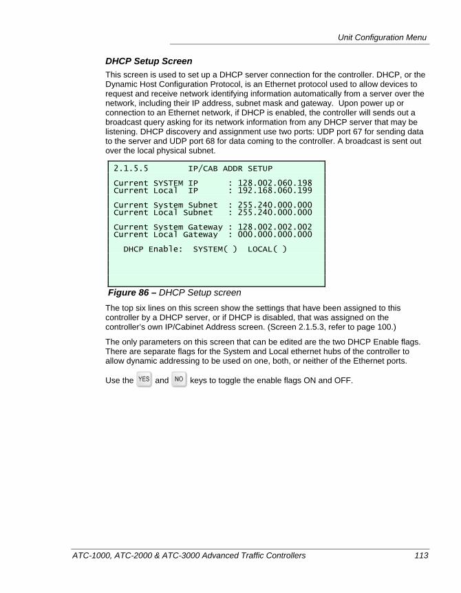
Unit Configuration Menu
ATC-1000, ATC-2000 & ATC-3000 Advanced Traffic Controllers 113
DHCP Setup Screen This screen is used to set up a DHCP server connection for the controller. DHCP, or the Dynamic Host Configuration Protocol, is an Ethernet protocol used to allow devices to request and receive network identifying information automatically from a server over the network, including their IP address, subnet mask and gateway. Upon power up or connection to an Ethernet network, if DHCP is enabled, the controller will sends out a broadcast query asking for its network information from any DHCP server that may be listening. DHCP discovery and assignment use two ports: UDP port 67 for sending data to the server and UDP port 68 for data coming to the controller. A broadcast is sent out over the local physical subnet.
2.1.5.5 IP/CAB ADDR SETUP Current SYSTEM IP : 128.002.060.198 Current Local IP : 192.168.060.199 Current System Subnet : 255.240.000.000 Current Local Subnet : 255.240.000.000 Current System Gateway : 128.002.002.002 Current Local Gateway : 000.000.000.000 DHCP Enable: SYSTEM( ) LOCAL( )
Figure 86 – DHCP Setup screen The top six lines on this screen show the settings that have been assigned to this controller by a DHCP server, or if DHCP is disabled, that was assigned on the controller’s own IP/Cabinet Address screen. (Screen 2.1.5.3, refer to page 100.)
The only parameters on this screen that can be edited are the two DHCP Enable flags. There are separate flags for the System and Local ethernet hubs of the controller to allow dynamic addressing to be used on one, both, or neither of the Ethernet ports.
Use the and keys to toggle the enable flags ON and OFF.
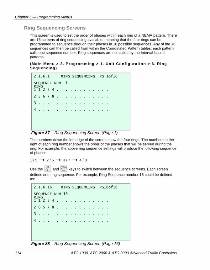
Chapter 5 — Programming Menus
114 ATC-1000, ATC-2000 & ATC-3000 Advanced Traffic Controllers
Ring Sequencing Screens This screen is used to set the order of phases within each ring of a NEMA pattern. There are 16 screens of ring sequencing available, meaning that the four rings can be programmed to sequence through their phases in 16 possible sequences. Any of the 16 sequences can then be called from within the Coordinated Pattern tables; each pattern calls one sequence number. Ring sequences are not called by the Interval-based patterns.
(Main Menu > 2. Programming > 1. Unit Configurat ion > 6. Ring Sequencing)
2.1.6.1 RING SEQUENCING PG 1of16 SEQUENCE NUM 1 RING 1 1 2 3 4 . . . . . . . . . . . . 2 5 6 7 8 . . . . . . . . . . . . 3 . . . . . . . . . . . . . . . . 4 . . . . . . . . . . . . . . . .
Figure 87 – Ring Sequencing Screen (Page 1) The numbers down the left edge of the screen show the four rings. The numbers to the right of each ring number shows the order of the phases that will be served during the ring. For example, the above ring sequence settings will produce the following sequence of phases:
1 / 5 2 / 6 3 / 7 4 / 8
Use the and keys to switch between the sequence screens. Each screen defines one ring sequence. For example, Ring Sequence number 16 could be defined as:
2.1.6.16 RING SEQUENCING PG16of16 SEQUENCE NUM 16 RING 1 1 2 3 4 . . . . . . . . . . . . 2 6 5 7 8 . . . . . . . . . . . . 3 . . . . . . . . . . . . . . . . 4 . . . . . . . . . . . . . . . .
Figure 88 – Ring Sequencing Screen (Page 16)
Unit Configuration Menu
ATC-1000, ATC-2000 & ATC-3000 Advanced Traffic Controllers 115
The sequence defined above is an example of a Lead/Lag sequence:
1 / 6 2 / 6 2 / 5 3 / 7 4 / 8
Note These settings can be used with the Phase Compatibility programming of the controller (Screen 2.1.3) to develop any sequence desired.
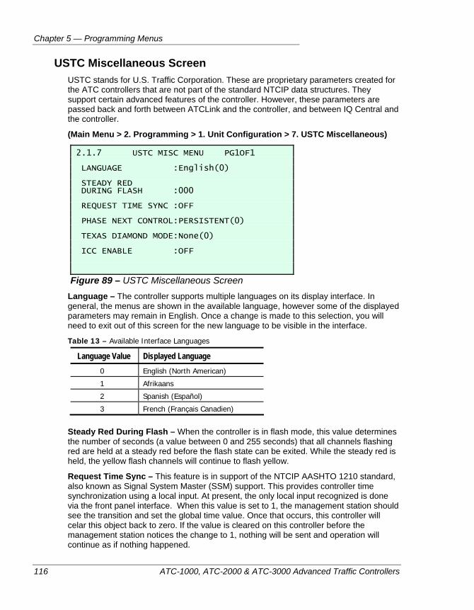
Chapter 5 — Programming Menus
116 ATC-1000, ATC-2000 & ATC-3000 Advanced Traffic Controllers
USTC Miscellaneous Screen USTC stands for U.S. Traffic Corporation. These are proprietary parameters created for the ATC controllers that are not part of the standard NTCIP data structures. They support certain advanced features of the controller. However, these parameters are passed back and forth between ATCLink and the controller, and between IQ Central and the controller.
(Main Menu > 2. Programming > 1. Unit Configuration > 7. USTC Miscellaneous)
2.1.7 USTC MISC MENU PG1OF1 LANGUAGE :English(0) STEADY RED DURING FLASH :000 REQUEST TIME SYNC :OFF PHASE NEXT CONTROL:PERSISTENT(0) TEXAS DIAMOND MODE:None(0) ICC ENABLE :OFF
Figure 89 – USTC Miscellaneous Screen Language – The controller supports multiple languages on its display interface. In general, the menus are shown in the available language, however some of the displayed parameters may remain in English. Once a change is made to this selection, you will need to exit out of this screen for the new language to be visible in the interface.
Table 13 – Available Interface Languages
Language Value Displayed Language 0 English (North American)
1 Afrikaans
2 Spanish (Español)
3 French (Français Canadien)
Steady Red During Flash – When the controller is in flash mode, this value determines the number of seconds (a value between 0 and 255 seconds) that all channels flashing red are held at a steady red before the flash state can be exited. While the steady red is held, the yellow flash channels will continue to flash yellow.
Request Time Sync – This feature is in support of the NTCIP AASHTO 1210 standard, also known as Signal System Master (SSM) support. This provides controller time synchronization using a local input. At present, the only local input recognized is done via the front panel interface. When this value is set to 1, the management station should see the transition and set the global time value. Once that occurs, this controller will celar this object back to zero. If the value is cleared on this controller before the management station notices the change to 1, nothing will be sent and operation will continue as if nothing happened.
Unit Configuration Menu
ATC-1000, ATC-2000 & ATC-3000 Advanced Traffic Controllers 117
Phase Next Control – This setting determines how the controller handles the ‘Phase Next’ decision within an intersection cycle. Possible values are: Persistent (0) or Not Persistent (1). If Phase Next is set to persistent, at the end of Green, the controller will attempt to make a Phase Next decision. If a phase next is found, that decision will be retained unless a higher priority event occurs and causes the controller to re-comit the ring. If a decisions cannot be made at the end of green, it will try again at the end of red clearance.
If the Phase Next Control is set to Not Persistent, again, at the end of green, the controller will attempt to make a Phase Next decision. Even if it decides on a next phase, that decision will continue to be tested during the clearance phase, until the last possible tenth of a second is reached, just before the end of red clearance. Once red clearance is reached, the Phase Next decision will bring up the new phases. This is a ‘real-time’ approach to the Phase Next decision process. It allows for truly ‘real-time’ actuated operations.
Caution In some cases, using Not Persistent control will cause overlaps to
terminate when the Phase Next decision is changed and is no longer a Parent phase of the overlap. In such a case, the controller would hold the ring in red until the overlap clears.
Texas Diamond Mode – This switch is used to enable and disable Texas Diamond mode, which allows a pair of intersections on either side of a highway to be managed in a coordinated fashion by a single controller. Texas Diamond mode uses automatically programmed Dynamic Omits and Recalls to time the two intersections. At this time, Texas Diamond mode does not function within the controller, and any choice made here will not impact the operation of an intersection.
ICC Enable – Used to enable or disable the ICC railroad CRC checking function, for the Illinois Commerce Commission railroad preemption standard. Can be set to ON or OFF
using the key.
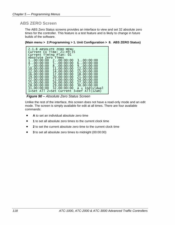
Chapter 5 — Programming Menus
118 ATC-1000, ATC-2000 & ATC-3000 Advanced Traffic Controllers
ABS ZERO Screen The ABS Zero Status screens provides an interface to view and set 32 absolute zero times for the controller. This feature is a test feature and is likely to change in future builds of the software.
(Main menu > 2.Programming > 1. Unit Configuration > 8. ABS ZERO Status)
2.1.8 ABSOLUTE ZERO MENU Current CU Time: 21:49:35 Current Timing Plan: 01 Absolute Zero Times 1..00:00:00 2..00:00:00 3..00:00:00 4..00:00:00 5..00:00:00 6..00:00:00 7..00:00:00 8..00:00:00 9..00:00:00 10.00:00:00 11.00:00:00 12.00:00:00 12.00:00:00 14.00:00:00 15.00:00:00 16.00:00:00 17.00:00:00 18.00:00:00 19.00:00:00 20.00:00:00 21.00:00:00 22.00:00:00 23.00:00:00 24.00:00:00 25.00:00:00 26.00:00:00 27.00:00:00 28.00:00:00 29.00:00:00 30.00:00:00 31.00:00:00 32.00:00:00 A = Individual 1=Set All 2=Set Current 3=Def All(12am)
Figure 90 – Absolute Zero Status Screen Unlike the rest of the interface, this screen does not have a read-only mode and an edit mode. The screen is simply available for edit at all times. There are four available commands:
A to set an individual absolute zero time
1 to set all absolute zero times to the current clock time
2 to set the current absolute zero time to the current clock time
3 to set all absolute zero times to midnight (00:00:00)
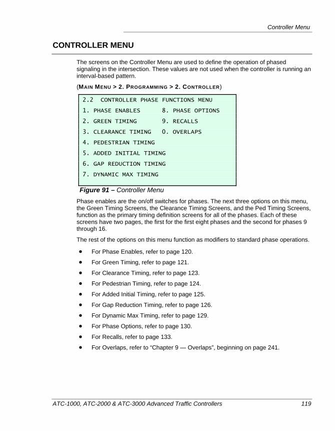
Controller Menu
ATC-1000, ATC-2000 & ATC-3000 Advanced Traffic Controllers 119
CONTROLLER MENU
The screens on the Controller Menu are used to define the operation of phased signaling in the intersection. These values are not used when the controller is running an interval-based pattern.
(MAIN MENU > 2. PROGRAMMING > 2. CONTROLLER)
2.2 CONTROLLER PHASE FUNCTIONS MENU 1. PHASE ENABLES 8. PHASE OPTIONS 2. GREEN TIMING 9. RECALLS 3. CLEARANCE TIMING 0. OVERLAPS 4. PEDESTRIAN TIMING 5. ADDED INITIAL TIMING 6. GAP REDUCTION TIMING 7. DYNAMIC MAX TIMING
Figure 91 – Controller Menu Phase enables are the on/off switches for phases. The next three options on this menu, the Green Timing Screens, the Clearance Timing Screens, and the Ped Timing Screens, function as the primary timing definition screens for all of the phases. Each of these screens have two pages, the first for the first eight phases and the second for phases 9 through 16.
The rest of the options on this menu function as modifiers to standard phase operations.
For Phase Enables, refer to page 120.
For Green Timing, refer to page 121.
For Clearance Timing, refer to page 123.
For Pedestrian Timing, refer to page 124.
For Added Initial Timing, refer to page 125.
For Gap Reduction Timing, refer to page 126.
For Dynamic Max Timing, refer to page 129.
For Phase Options, refer to page 130.
For Recalls, refer to page 133.
For Overlaps, refer to “Chapter 9 — Overlaps”, beginning on page 241.
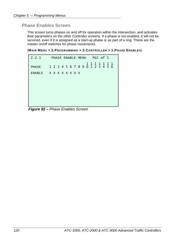
Chapter 5 — Programming Menus
120 ATC-1000, ATC-2000 & ATC-3000 Advanced Traffic Controllers
Phase Enables Screen This screen turns phases on and off for operation within the intersection, and activates their parameters on the other Controller screens. If a phase is not enabled, it will not be serviced, even if it is assigned as a start-up phase or as part of a ring. These are the master on/off switches for phase movements.
(MAIN MENU > 2.PROGRAMMING > 2.CONTROLLER > 1.PHASE ENABLES)
2.2.1 PHASE ENABLE MENU PG1 of 1 1 1 1 1 1 1 1 PHASE 1 2 3 4 5 6 7 8 9 0 1 2 3 4 5 6 ENABLE X X X X X X X X
Figure 92 – Phase Enables Screen
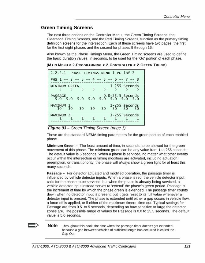
Controller Menu
ATC-1000, ATC-2000 & ATC-3000 Advanced Traffic Controllers 121
Green Timing Screens The next three options on the Controller Menu, the Green Timing Screens, the Clearance Timing Screens, and the Ped Timing Screens, function as the primary timing definition screens for the intersection. Each of these screens have two pages, the first for the first eight phases and the second for phases 9 through 16.
Also known as the Phase Timings Menu, the Green Timing screens are used to define the basic duration values, in seconds, to be used for the ‘Go’ portion of each phase.
(MAIN MENU > 2.PROGRAMMING > 2.CONTROLLER > 2.GREEN TIMING)
2.2.2.1 PHASE TIMINGS MENU 1 PG 1of 2 PHS 1 -- 2 -- 3 -- 4 -- 5 -- 6 -- 7 -- 8 ---------------------------------------- MINIMUM GREEN 1-255 Seconds 5 5 5 5 5 5 5 5 PASSAGE 0.0-25.5 Seconds 5.0 5.0 5.0 5.0 5.0 5.0 5.0 5.0 MAXIMUM 1 1-255 Seconds 30 30 30 30 30 30 30 30 MAXIMUM 2 1-255 Seconds 1 1 1 1 1 1 1 1 ----------------------------------------
Figure 93 – Green Timing Screen (page 1) These are the standard NEMA timing parameters for the green portion of each enabled phase.
Minimum Green – The least amount of time, in seconds, to be allowed for the green movement of this phase. The minimum green can be any value from 1 to 255 seconds. The default value is 5 seconds. When a phase is serviced, no matter what other events occur within the intersection or timing modifiers are activated, including actuation, preemption, or transit priority, the phase will always show a green light for at least this many seconds.
Passage – For detector actuated and modified operation, the passage timer is influenced by vehicle detector inputs. When a phase is red, the vehicle detector input calls for the phase to be serviced, but when the phase is already being serviced, a vehicle detector input instead serves to ‘extend’ the phase’s green period. Passage is the increment of time by which the phase green is extended. The passage timer counts down when no detector input is present, but it gets reset to its full value whenever a detector input is present. The phase is extended until either a gap occurs in vehicle flow, a force-off is applied, or if either of the maximum timers time out. Typical settings for Passage are from 0.5 to 5 seconds, depending on how sensitive or large the detector zones are. The possible range of values for Passage is 0.0 to 25.5 seconds. The default value is 5.0 seconds.
Note Throughout this book, the time when the passage timer doesn’t get extended because a gap between vehicles of sufficient length has occurred is called the Gap-Out.
Chapter 5 — Programming Menus
122 ATC-1000, ATC-2000 & ATC-3000 Advanced Traffic Controllers
Maximum 1 – Maximum 1 timing is the default value used to set the maximum amount of time allowed for the green in this phase. For an actuated phase, this is the upper limit of the amount of green time allowed, as long as the phase is not in Maximum Recall mode. When Maximum Recall is not set to be ON for this phase, the Maximum 1 timer times down only when a serviceable, conflicting call is present. The phase remains green until the Passage timer fails to be reset by a vehicle detection, or until the Maximum 1 timer reaches zero, whichever comes first. This timer will cease timing and reset if all serviceable calls go away. The timer will re-start, if a new call arrives and the active conflicting phases are in the Passage interval.
However, when Maximum Recall is set to be ON for this phase, the phase is always served and the Maximum 1 timer always counts down to, whether or not there is a call on the detectors of any other phase.
The value of Maximum 1 can vary widely, but to give a feel for the range, its value is typically between 8 and 17 seconds for left turns, between 12 and 25 seconds for side streets, and between 22 and 40 seconds for main streets. The default value is 30 seconds.
Note If the Maximum 1 value is set to a very low number (such as 1 second) then minimum timing requirements for the phase, such as Min Green, will override it.
Maximum 2 – Maximum 2 is an alternate value for the maximum allowed amount of time allowed for this phase to be green. Max 2 is activated, on a ring by ring basis, by either an external input or by a TOD pattern change. When Max 2 is active the Maximum countdown timer will be loaded with the Maximum 2 value instead of the usual Maximum 1 time. When setting a value for the Maximum 2 field, the same concepts apply as with Maximum 1, except an alternate value is used. Maximum 2 is sometimes used during peak traffic periods (i.e. to generate longer main street flow times.) It is also sometimes used during coordination, so that phases won’t time out before being forced off.
Again, if the Maximum 2 time value is set to a very low number (such as 1 second) then minimum timing requirements for the phase, in other words, the Minimum Green value, will override it.

Controller Menu
ATC-1000, ATC-2000 & ATC-3000 Advanced Traffic Controllers 123
Clearance Timing Screens Collectively, the Green, Clearance, and Ped Timing Screens function as the primary timing definitions for phase-based intersection patterns. Each of these screens have two pages, the first for the first eight phases and the second for phases 9 through 16. The Clearance Timing Screens allow the user to set timing values for the yellow and red portions of each phase.
(MAIN MENU > 2.PROGRAMMING > 2.CONTROLLER > 3.CLEARANCE TIMING)
2.2.3.1 CLEARANCE TIMINGS MENU PG 1of 2 PHS 1 -- 2 -- 3 -- 4 -- 5 -- 6 -- 7 -- 8 ---------------------------------------- YELLOW CLEARANCE 3.0-25.5 Seconds 3.0 3.0 3.0 3.0 3.0 3.0 3.0 3.0 RED CLEARANCE 0.0-25.5 Seconds 2.0 2.0 2.0 2.0 2.0 2.0 2.0 2.0 RED REVERT 0.0-25.5 Seconds 0.0 0.0 0.0 0.0 0.0 0.0 0.0 0.0 ----------------------------------------
Figure 94 – Clearance Timing Screen (Page 1) Yellow Clearance – Quite simply, this is the amount of time the phase will spend showing the yellow signal. Yellow clearance can be set to any value between 3.0 and 25.5 seconds. Typical settings are from 3.5 to 5 seconds, based on the travel speed of traffic and the width of the intersection. The default value is 3.0 seconds.
Red Clearance – Obviously, phases sit in red whenever other phases are being served, but there is a short period in the interval when switching from the service of one phase to the next when the entire intersection must display ‘All Red’. Red Clearance defines how long this ‘rest’ period is. Values from 0.0 to 25.5 seconds can be entered, but typically this value is between 0 and 2.5 seconds. It is recommended that you use a time of at least 1 second for the Red Clearance value. The default value is 2.0 seconds.
Red Revert – Red Revert time deals with special occasions when a phase may complete its service, and the timing circuit or the coordinator of the controller decides to service the exact same phase again. When this occurs, the red revert time serves as the minimum red time before the phase is switched to green again. It is usually set to a value that is higher than Red Clearance. Typically, Red Revert comes up when the controller is asked to switch into a preemption sequence, or when switching patterns during TOD operation. Values from 0.0 to 25.5 seconds can be entered. The default value is set to 0.0 to allow the global Red Revert value on the Start-up menu to take precidence.
Note The Red Revert time shown here varies from the Red Revert parameter visible on the Start-up Menu. The Red Revert shown there is a unit global value. The parameter shown here, on the other hand, allows the user to set a red revert value per phase that is longer than the global value. The greater of the two values will be used.
Use the and keys to switch between the two clearance timing screens.
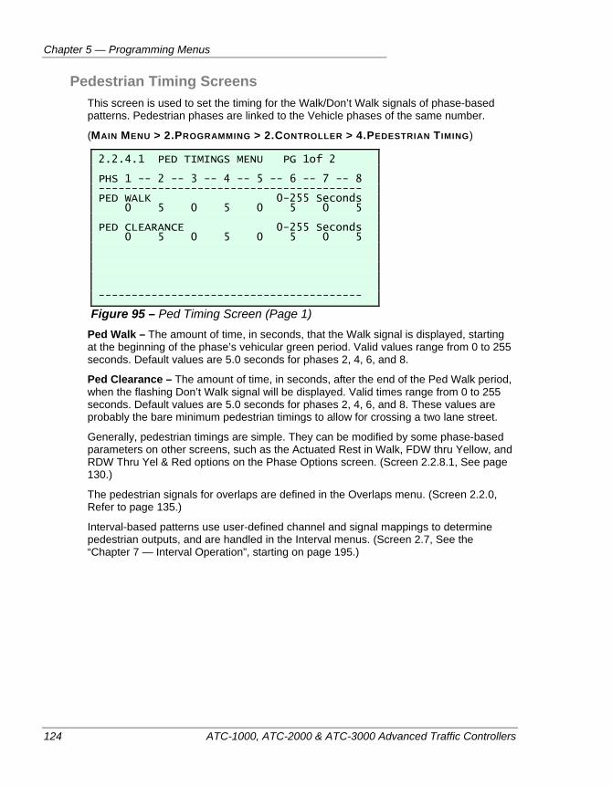
Chapter 5 — Programming Menus
124 ATC-1000, ATC-2000 & ATC-3000 Advanced Traffic Controllers
Pedestrian Timing Screens This screen is used to set the timing for the Walk/Don’t Walk signals of phase-based patterns. Pedestrian phases are linked to the Vehicle phases of the same number.
(MAIN MENU > 2.PROGRAMMING > 2.CONTROLLER > 4.PEDESTRIAN TIMING)
2.2.4.1 PED TIMINGS MENU PG 1of 2 PHS 1 -- 2 -- 3 -- 4 -- 5 -- 6 -- 7 -- 8 ---------------------------------------- PED WALK 0-255 Seconds 0 5 0 5 0 5 0 5 PED CLEARANCE 0-255 Seconds 0 5 0 5 0 5 0 5 ----------------------------------------
Figure 95 – Ped Timing Screen (Page 1) Ped Walk – The amount of time, in seconds, that the Walk signal is displayed, starting at the beginning of the phase’s vehicular green period. Valid values range from 0 to 255 seconds. Default values are 5.0 seconds for phases 2, 4, 6, and 8.
Ped Clearance – The amount of time, in seconds, after the end of the Ped Walk period, when the flashing Don’t Walk signal will be displayed. Valid times range from 0 to 255 seconds. Default values are 5.0 seconds for phases 2, 4, 6, and 8. These values are probably the bare minimum pedestrian timings to allow for crossing a two lane street.
Generally, pedestrian timings are simple. They can be modified by some phase-based parameters on other screens, such as the Actuated Rest in Walk, FDW thru Yellow, and RDW Thru Yel & Red options on the Phase Options screen. (Screen 2.2.8.1, See page 130.)
The pedestrian signals for overlaps are defined in the Overlaps menu. (Screen 2.2.0, Refer to page 135.)
Interval-based patterns use user-defined channel and signal mappings to determine pedestrian outputs, and are handled in the Interval menus. (Screen 2.7, See the “Chapter 7 — Interval Operation”, starting on page 195.)
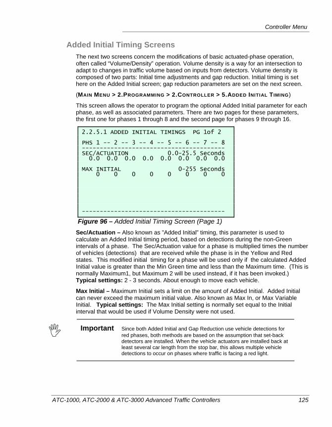
Controller Menu
ATC-1000, ATC-2000 & ATC-3000 Advanced Traffic Controllers 125
Added Initial Timing Screens The next two screens concern the modifications of basic actuated-phase operation, often called “Volume/Density” operation. Volume density is a way for an intersection to adapt to changes in traffic volume based on inputs from detectors. Volume density is composed of two parts: Initial time adjustments and gap reduction. Initial timing is set here on the Added Initial screen; gap reduction parameters are set on the next screen.
(MAIN MENU > 2.PROGRAMMING > 2.CONTROLLER > 5.ADDED INITIAL TIMING)
This screen allows the operator to program the optional Added Initial parameter for each phase, as well as associated parameters. There are two pages for these parameters, the first one for phases 1 through 8 and the second page for phases 9 through 16.
2.2.5.1 ADDED INITIAL TIMINGS PG 1of 2 PHS 1 -- 2 -- 3 -- 4 -- 5 -- 6 -- 7 -- 8 ---------------------------------------- SEC/ACTUATION 0.0-25.5 Seconds 0.0 0.0 0.0 0.0 0.0 0.0 0.0 0.0 MAX INITIAL 0-255 Seconds 0 0 0 0 0 0 0 0 ----------------------------------------
Figure 96 – Added Initial Timing Screen (Page 1) Sec/Actuation – Also known as ”Added Initial” timing, this parameter is used to calculate an Added Initial timing period, based on detections during the non-Green intervals of a phase. The Sec/Actuation value for a phase is multiplied times the number of vehicles (detections) that are received while the phase is in the Yellow and Red states. This modified initial timing for a phase will be used only if the calculated Added Initial value is greater than the Min Green time and less than the Maximum time. (This is normally Maximum1, but Maximum 2 will be used instead, if it has been invoked.) Typical settings: 2 - 3 seconds. About enough to move each vehicle.
Max Initial – Maximum Initial sets a limit on the amount of Added Initial. Added Initial can never exceed the maximum initial value. Also known as Max In, or Max Variable Initial. Typical settings: The Max Initial setting is normally set equal to the Initial interval that would be used if Volume Density were not used.
Important Since both Added Initial and Gap Reduction use vehicle detections for
red phases, both methods are based on the assumption that set-back detectors are installed. When the vehicle actuators are installed back at least several car length from the stop bar, this allows multiple vehicle detections to occur on phases where traffic is facing a red light.
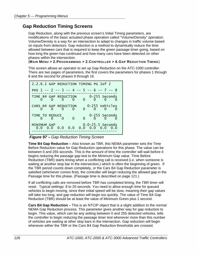
Chapter 5 — Programming Menus
126 ATC-1000, ATC-2000 & ATC-3000 Advanced Traffic Controllers
Gap Reduction Timing Screens Gap Reduction, along with the previous screen’s Initial Timing parameters, are modifications of the basic actuated phase operation called “Volume/Density” operation. Volume/Density is a way for an intersection to adapt to changes in traffic volume based on inputs from detectors. Gap reduction is a method to dynamically reduce the time allowed between cars that is required to keep the green passage timer going, based on how long the green has continued and how many cars have been detected on other phases within the intersection. (MAIN MENU > 2.PROGRAMMING > 2.CONTROLLER > 6.GAP REDUCTION TIMING)
This screen allows an operator to set up Gap Reduction on the ATC-1000 controller. There are two pages of parameters, the first covers the parameters for phases 1 through 8 and the second for phases 9 through 16.
2.2.6.1 GAP REDUCTION TIMING PG 1of 2 PHS 1 -- 2 -- 3 -- 4 -- 5 -- 6 -- 7 -- 8 ---------------------------------------- TIME B4 GAP REDUCTION 0-255 Seconds 0 0 0 0 0 0 0 0 CARS B4 GAP REDUCTION 0-255 Vehicles 0 0 0 0 0 0 0 0 TIME TO REDUCE 0-255 Seconds 0 0 0 0 0 0 0 0 MINIMUM GAP 0.0-25.5 Seconds 0.0 0.0 0.0 0.0 0.0 0.0 0.0 0.0 ----------------------------------------
Figure 97 – Gap Reduction Timing Screen Time B4 Gap Reduction – Also known as TBR, this NEMA parameter sets the Time Before Reduction value for Gap Reduction operations for this phase. The value can be between 0 and 255 seconds. This is the amount of time the controller will wait before it begins reducing the passage gap test to the Minimum Gap value. Time Before Reduction (TBR) starts timing when a conflicting call is received (i.e. when someone is waiting at another stop bar in the intersection,) which is often the beginning of green. If the TBR period counts down completely, or the Cars B4 Gap Reduction parameter is satisfied (whichever comes first), the controller will begin reducing the allowed gap in the Passage time for this phase. (Passage time is described on page 121.)
If all conflicting calls are removed before TBR has completed timing, the TBR timer will reset. Typical settings: 8 to 20 seconds. You need to allow enough time for queued vehicles to begin moving, since their initial speed will be slow, meaning their gap values will take too long, and gap reduction will begin too quickly. The value of Time B4 Gap Reduction (TBR) should be at least the value of Minimum Green plus 1 second.
Cars B4 Gap Reduction – This is an NTCIP object that is a slight addition to the normal NEMA Gap Reduction process. This parameter gives another way for gap reduction to begin. This value, which can be any setting between 0 and 255 detected vehicles, tells the controller to begin reducing the passage timer test whenever more than this number of vehicles are waiting at other stop bars in the intersection. Gap reduction will begin whenever either the TBR or the Cars B4 Gap Reduction thresholds are crossed.
Controller Menu
ATC-1000, ATC-2000 & ATC-3000 Advanced Traffic Controllers 127
Time to Reduce – Time to Reduce (TTR) is a NEMA parameter that establishes the time reduction step that the controller will use to begin a linear reduction of the phase gap (passage time) down to the minimum gap time. This value can be anything between 0 and 255 seconds, but typical settings are between 4 and 12 seconds. The size of TTR depends on how quickly the operator wishes to close the timing gap. A larger TTR closes the gap more quickly. If one wishes to close the gap immediately in one reduction step, the value of TTR should be the entire difference between the Passage time and the Minimum Gap value.
Minimum Gap – Minimum Gap is another standard NEMA parameter of the gap reduction process. The minimum gap value establishes the lowest acceptable gap (passage time) in traffic. The gap test will not be reduced below this amount. So if cars continue to cross the vehicle detectors at a rate that leaves no gaps larger than this Minimum Gap value, the Passage timer for the green portion of this phase will be extended right up until the Maximum timer times out. The acceptable range for minimum gap is from 0.0 to 25.5 seconds. Typical settings for Minimum Gap are from 1 to 3 seconds.
Note In the presence of a continuous vehicle actuation, the phase will not gap out even if Minimum Gap is set at zero.
Notes About the Usage of Gap Reduction Gap reduction allows the normal passage time for a phase to be reduced linearly during the green portion of the phase. The parameters associated with this operation are called Time Before Reduction (TBR), Cars Before Reduction, Time To Reduce (TTR) and Min Gap. Thus, the longer demand holds a phase green even though a conflicting call is present, the closer the vehicles must be spaced to retain the existing green interval. The following are the two typical uses of gap reduction:
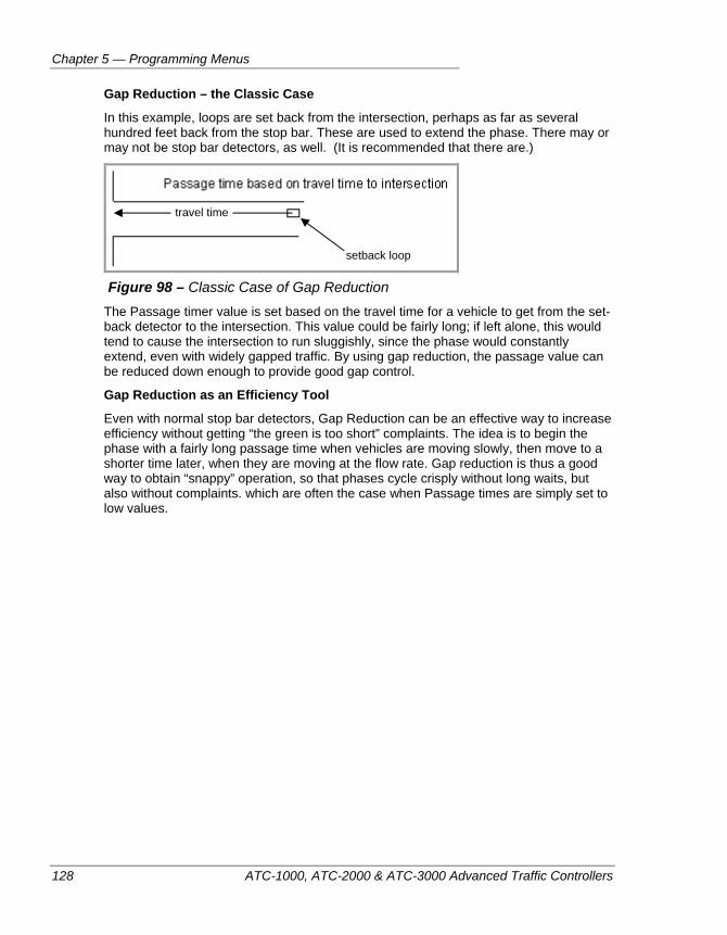
Chapter 5 — Programming Menus
128 ATC-1000, ATC-2000 & ATC-3000 Advanced Traffic Controllers
Gap Reduction – the Classic Case
In this example, loops are set back from the intersection, perhaps as far as several hundred feet back from the stop bar. These are used to extend the phase. There may or may not be stop bar detectors, as well. (It is recommended that there are.)
Figure 98 – Classic Case of Gap Reduction
The Passage timer value is set based on the travel time for a vehicle to get from the set-back detector to the intersection. This value could be fairly long; if left alone, this would tend to cause the intersection to run sluggishly, since the phase would constantly extend, even with widely gapped traffic. By using gap reduction, the passage value can be reduced down enough to provide good gap control.
Gap Reduction as an Efficiency Tool
Even with normal stop bar detectors, Gap Reduction can be an effective way to increase efficiency without getting “the green is too short” complaints. The idea is to begin the phase with a fairly long passage time when vehicles are moving slowly, then move to a shorter time later, when they are moving at the flow rate. Gap reduction is thus a good way to obtain “snappy” operation, so that phases cycle crisply without long waits, but also without complaints. which are often the case when Passage times are simply set to low values.
setback loop
travel time
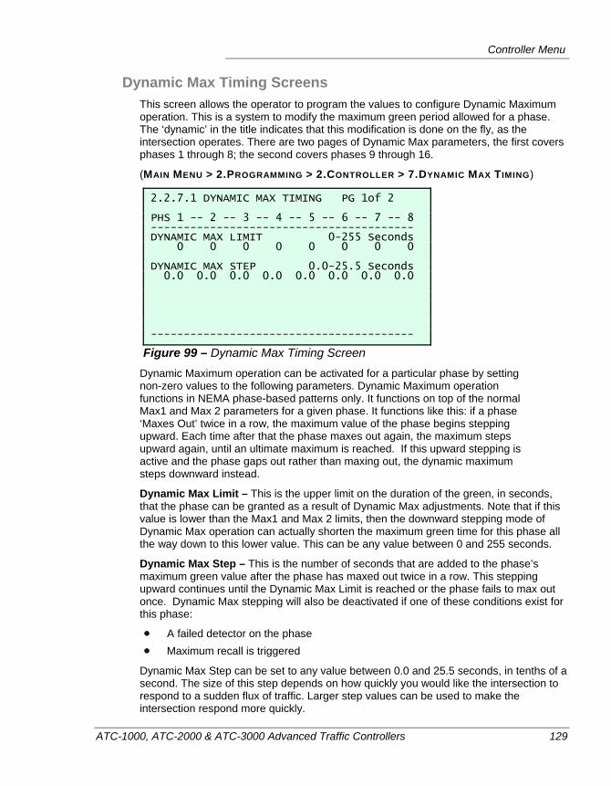
Controller Menu
ATC-1000, ATC-2000 & ATC-3000 Advanced Traffic Controllers 129
Dynamic Max Timing Screens This screen allows the operator to program the values to configure Dynamic Maximum operation. This is a system to modify the maximum green period allowed for a phase. The ‘dynamic’ in the title indicates that this modification is done on the fly, as the intersection operates. There are two pages of Dynamic Max parameters, the first covers phases 1 through 8; the second covers phases 9 through 16.
(MAIN MENU > 2.PROGRAMMING > 2.CONTROLLER > 7.DYNAMIC MAX TIMING)
2.2.7.1 DYNAMIC MAX TIMING PG 1of 2 PHS 1 -- 2 -- 3 -- 4 -- 5 -- 6 -- 7 -- 8 ---------------------------------------- DYNAMIC MAX LIMIT 0-255 Seconds 0 0 0 0 0 0 0 0 DYNAMIC MAX STEP 0.0-25.5 Seconds 0.0 0.0 0.0 0.0 0.0 0.0 0.0 0.0 ----------------------------------------
Figure 99 – Dynamic Max Timing Screen Dynamic Maximum operation can be activated for a particular phase by setting non-zero values to the following parameters. Dynamic Maximum operation functions in NEMA phase-based patterns only. It functions on top of the normal Max1 and Max 2 parameters for a given phase. It functions like this: if a phase ‘Maxes Out’ twice in a row, the maximum value of the phase begins stepping upward. Each time after that the phase maxes out again, the maximum steps upward again, until an ultimate maximum is reached. If this upward stepping is active and the phase gaps out rather than maxing out, the dynamic maximum steps downward instead.
Dynamic Max Limit – This is the upper limit on the duration of the green, in seconds, that the phase can be granted as a result of Dynamic Max adjustments. Note that if this value is lower than the Max1 and Max 2 limits, then the downward stepping mode of Dynamic Max operation can actually shorten the maximum green time for this phase all the way down to this lower value. This can be any value between 0 and 255 seconds.
Dynamic Max Step – This is the number of seconds that are added to the phase’s maximum green value after the phase has maxed out twice in a row. This stepping upward continues until the Dynamic Max Limit is reached or the phase fails to max out once. Dynamic Max stepping will also be deactivated if one of these conditions exist for this phase:
A failed detector on the phase Maximum recall is triggered
Dynamic Max Step can be set to any value between 0.0 and 25.5 seconds, in tenths of a second. The size of this step depends on how quickly you would like the intersection to respond to a sudden flux of traffic. Larger step values can be used to make the intersection respond more quickly.
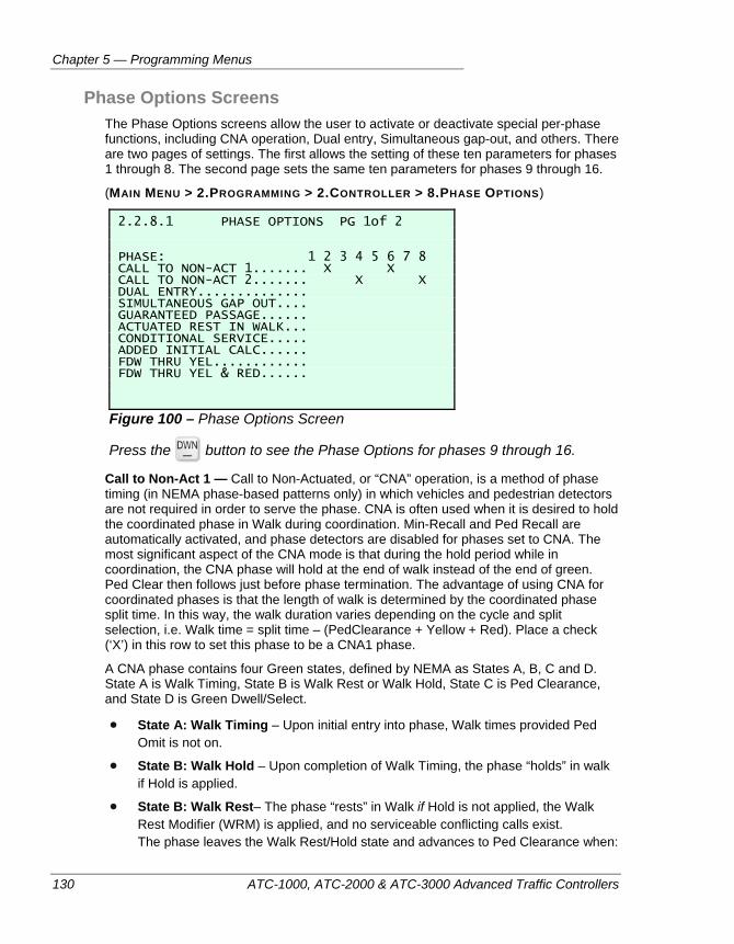
Chapter 5 — Programming Menus
130 ATC-1000, ATC-2000 & ATC-3000 Advanced Traffic Controllers
Phase Options Screens The Phase Options screens allow the user to activate or deactivate special per-phase functions, including CNA operation, Dual entry, Simultaneous gap-out, and others. There are two pages of settings. The first allows the setting of these ten parameters for phases 1 through 8. The second page sets the same ten parameters for phases 9 through 16.
(MAIN MENU > 2.PROGRAMMING > 2.CONTROLLER > 8.PHASE OPTIONS)
2.2.8.1 PHASE OPTIONS PG 1of 2 PHASE: 1 2 3 4 5 6 7 8 CALL TO NON-ACT 1....... X X CALL TO NON-ACT 2....... X X DUAL ENTRY.............. SIMULTANEOUS GAP OUT.... GUARANTEED PASSAGE...... ACTUATED REST IN WALK... CONDITIONAL SERVICE..... ADDED INITIAL CALC...... FDW THRU YEL............ FDW THRU YEL & RED......
Figure 100 – Phase Options Screen
Press the button to see the Phase Options for phases 9 through 16.
Call to Non-Act 1 — Call to Non-Actuated, or “CNA” operation, is a method of phase timing (in NEMA phase-based patterns only) in which vehicles and pedestrian detectors are not required in order to serve the phase. CNA is often used when it is desired to hold the coordinated phase in Walk during coordination. Min-Recall and Ped Recall are automatically activated, and phase detectors are disabled for phases set to CNA. The most significant aspect of the CNA mode is that during the hold period while in coordination, the CNA phase will hold at the end of walk instead of the end of green. Ped Clear then follows just before phase termination. The advantage of using CNA for coordinated phases is that the length of walk is determined by the coordinated phase split time. In this way, the walk duration varies depending on the cycle and split selection, i.e. Walk time = split time – (PedClearance + Yellow + Red). Place a check (‘X’) in this row to set this phase to be a CNA1 phase.
A CNA phase contains four Green states, defined by NEMA as States A, B, C and D. State A is Walk Timing, State B is Walk Rest or Walk Hold, State C is Ped Clearance, and State D is Green Dwell/Select.
State A: Walk Timing – Upon initial entry into phase, Walk times provided Ped Omit is not on.
State B: Walk Hold – Upon completion of Walk Timing, the phase “holds” in walk if Hold is applied.
State B: Walk Rest– The phase “rests” in Walk if Hold is not applied, the Walk Rest Modifier (WRM) is applied, and no serviceable conflicting calls exist. The phase leaves the Walk Rest/Hold state and advances to Ped Clearance when:
Controller Menu
ATC-1000, ATC-2000 & ATC-3000 Advanced Traffic Controllers 131
a.) The phase is in Walk Rest and a serviceable conflicting call is registered, or
b.) The phase is in Walk Hold, a serviceable conflicting call exists and Force Off is applied, or
c.) Hold is released and the WRM is not active, regardless of the presence of a serviceable conflicting call.
State C: Ped Clearance – The phase times the Ped Clearance setting, and then advances to the Green Dwell/Select state.
State D: Green Dwell/Select – This is the state in which the controller does one of the following things, based on the current conditions:
a.) Immediately selects the next phase to be serviced and proceeds to yellow clearance, or
b.) it rests in Green/Don’t Walk if a call exists and concurrent timing constraints exist, or if WRM and Ped Recycle are not active, or
c.) it returns to Walk if no serviceable conflicting call exists and either WRM or Ped Recycle are active, and Ped Omit is not active. Once a CNA phase has left the Walk state, Hold and Force Off do not have an effect on the termination of the phase. That is, Force Off does not have to be maintained throughout Ped Clearance in order to terminate the green, nor will Hold maintain the phase in Green/Don’t Walk.
Call to Non-Act 2 — Place a check (‘X’) in this row to set this phase to be a CNA2 phase. CNA2 operates the same as CNA1, but it provides an alternative phase selection method for Call to Non-Actuated operation, usually for cross-arterial coordination.
Dual Entry — Place a check (‘X’) in this row to set this phase to be a Dual Entry phase. Dual Entry works in conjunction with the compatibility matrix of phases. (See page 95) Dual Entry is a flag on a phase that tells the controller that if a phase in the other ring comes on by itself, the controller can look across the barrier for a compatible phase that is marked as Dual Entry, and it will select one to turn on. This ensures that there will always be a phase on in each ring whenever the compatibility matrix permits it. Dual Entry is typically used during multi ring operation, to prevent a single phase from being served at a time. For example, suppose phase 8 gets called. The controller might serve it alone, except it notices that across the ring barrier, phase 4 is listed as both compatible with 8, AND it is a Dual Entry phase, so the controller goes ahead and turns phase 4 on at the same time.
Simultaneous Gap Out — Place a check (‘X’) in this row to set this phase to be a Simultaneous Gap Out phase. Simultaneous Gap Out, sometimes known as ‘SGO’, allows a phase’s passage timer to re-start if it has timed out and the phase is waiting to cross a barrier. With SGO enabled and calls on Phases 2 and 6, the Phase 4 passage timer can start again if a new vehicle arrives. If Phase 4 then extends and Phase 8 gaps out, Phase 8 can start its passage timer again. This operation can continue back and forth until both phases Max Out or they both “Simultaneously Gap Out”, hence the
Chapter 5 — Programming Menus
132 ATC-1000, ATC-2000 & ATC-3000 Advanced Traffic Controllers
name. When Simultaneous Gap Out is disabled, the phase passage timer cannot restart once it times out for the selected phases and is waiting to cross the barrier. If phase 4 goes to rest while 8 is extending, then 4 cannot start its passage timer again. Both phases will then gap out as soon as phase 8 does. So phases will tend to gap out sooner with SGO disabled than when it is enabled.
Guaranteed Passage — Place a check (‘X’) in this row to set this phase to be a Guaranteed Passage phase. When this is enabled for a phase that is operating in volume density mode, meaning it is using gap reduction, it allows the phase to retain the right-of-way for the unexpired portion of its Passage timer, following the decision to terminate the Green due to a reduced gap.
Actuated Rest in Walk — Place a check (‘X’) in this row to set this phase to be an Actuated Rest-in-Walk phase. This was called ‘Walk Rest’ or ‘WR’ in the 3000E controller. Allows the selected phase to rest in Green-Walk instead of Green-Don’t Walk, as long as there is no serviceable conflicting call at the end of the Walk timing.
Conditional Service — Place a check (‘X’) in this row to set this phase to be a Conditional Service phase. This is typically used to allow a left turn phase to be served twice in the same cycle; once as a leading phase and once as a lagging phase. This is only possible in a non-coordinated intersection. The following conditions are required to allow a conditional service phase to function in this way:
there is a call for service on a leading left-turn phase
the intersection is not working in coordination with any other intersection
There is a conflicting call on the opposite side of the barrier. Otherwise, the left-turn phase would be serviced automatically by standard actuated controller behavior, and conditional service isn’t required.
The through phase of the phase pair that includes this left turn has Gapped out.
The time remaining on the through phase’s maximum timer is larger than the left-turn’s minimum conditional service time.
Note that although conditional service is usually used to allow a second left turn during a cycle, it can in fact be used for any phase that meets the above criteria; just replace the ‘left-turn phase’ term in the requirement with ‘the conditional phase’.
Added Initial Calc — Place a check (‘X’) in this row to set this phase to be an ‘Added Initial’ phase. Added Initial is a form of Variable Initial timing, which increases the initial green interval of a phase based on the demand for that phase that is measured during the preceding yellow and red periods. The extra time allows a platoon of vehicles to proceed through the intersection before the passage time becomes active. The added-initial option is generally used when long minimum green times are specified. This method counts the number of detector counts during the non-green portion of the phase and uses that to add a multiple of the added initial time to the minimum green time. The total initial time will not exceed the defined Max initial time. The controller will compare all of the detectors associated with this phase and use the one that collected the largest number of vehicle counts. The values used in these calculations are entered on the “Added Initial Timing Screens”; see page 125.
FDW Thru YEL — Flashing Don’t Walk through the Yellow portion of the phase. The ‘clearance’ portion of the walk movement is normally timed using the values stored on
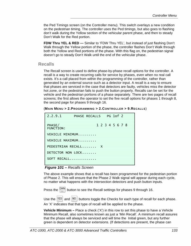
Controller Menu
ATC-1000, ATC-2000 & ATC-3000 Advanced Traffic Controllers 133
the Ped Timings screen (on the Controller menu). This switch overlays a new condition on the pedestrian timing. The controller uses the Ped timings, but also goes to flashing don’t walk during the Yellow section of the vehicular parent phase, and then to steady Don’t Walk for the Red portion.
FDW Thru YEL & RED — Similar to ‘FDW Thru YEL’, but instead of just flashing Don’t Walk through the Yellow portion of the phase, the controller flashes Don’t Walk through both the Yellow and Red portions of the phase. With this flag on, the pedestrian signal doesn’t go to steady Don’t Walk until the end of the vehicular phase.
Recalls The Recall screen is used to define phase-by-phase recall options for the controller. A recall is a way to create recurring calls for service by phases, even when no real call exists. It’s a call placed from within the programming of the controller, rather than generated by an external source such as a detector input. A recall is a way to ensure that phases are serviced in the case that detectors are faulty, vehicles miss the detector hot zone, or the pedestrian fails to push the button properly. Recalls can be set for the vehicle and the pedestrian portions of a phase separately. There are two pages of recall screens; the first allows the operator to set the five recall options for phases 1 through 8, the second page for phases 9 through 16.
(MAIN MENU > 2.PROGRAMMING > 2.CONTROLLER > 9.RECALLS)
2.2.9.1 PHASE RECALLS PG 1of 2 PHASE/ 1 2 3 4 5 6 7 8 FUNCTION: VEHICLE MINIMUM......... VEHICLE MAXIMUM......... PEDESTRIAN RECALL....... X DETECTOR NON LOCK....... SOFT RECALL.............
Figure 101 – Recalls Screen The above example shows that a recall has been programmed for the pedestrian portion of Phase 2. This will ensure that the Phase 2 Walk signal will appear during each cycle, no matter what happens with the intersection detectors and push button inputs.
Press the button to see the Recall settings for phases 9 through 16.
Use the and buttons toggle the Checks for each type of recall for each phase. An ‘X’ indicates that that type of recall will be applied to the phase.
Vehicle Minimum – Place a check (‘X’) in this row to set this phase to have a Vehicle Minimum Recall, also sometimes known as just a ‘Min Recall’. A minimum recall assures that the phase will always be serviced and will time the Initial green, but any further green is dependent on detector extensions. (If detections are present, the phase can
Chapter 5 — Programming Menus
134 ATC-1000, ATC-2000 & ATC-3000 Advanced Traffic Controllers
time up to the Max time.) If there is no demand on the phase, the controller will time the Initial interval only, then it will either rest (if there is no other demand) or advance to the next phase that has demand. A phase can operate in either Min Recall or Max Recall, but not both. If both are selected, then Max Recall will be used.
Vehicle Maximum – Place a check (‘X’) in this row to set this phase to have a Vehicle Maximum Recall, also sometimes known as just a ‘Max Recall’. This is similar to Min Recall, except that the phase will time the entire max time regardless of demand. Upon termination of the Max timer, the phase will either rest or advance to a phase that has demand. Maximum 1 is the default maximum used. Maximum 2 can be selected via an external input or via a Time of Day Action. Max Recall is typically used for any phase that is to be “pre-timed” i.e. it has no detection but must be served. Often used on a main street with no peds (or actuated peds) in a semi-actuated application where the side is actuated but the main street is not. Note that Max Recall should not be applied to phases with functional detection. It is sometimes applied to an actuated phase temporarily when detection fails. A phase can operate in either Min Recall or Max Recall, but not both. If both are selected, then Max Recall will be used.
Pedestrian Recall – Place a check (‘X’) in this row to set this phase to have a Pedestrian Recall, also sometimes known as just a ‘Ped Recall’. The pedestrian movement on this phase will be serviced once per cycle.
Detector Non Lock – Non-Lock disables vehicle call memory on selected phases. The phase only recognizes vehicle presence so that the detector must be continuously occupied in order to maintain a call for service. Note that the default mode is non-lock disabled (no “X”), which means that memory is on. Program an “X“ for phases to operate in Non-Lock mode (i.e. memory off, presence mode).
When Non-Lock is not enabled (locking mode), if the phase terminates with time remaining in the Passage Timer (i.e. Max, Force Off, Interval Advance), a call will be left on the phase and the unit will cycle back to it until the call is serviced.
Non lock enabled (X) should be used for phases where the detection zone is sufficient for presence type detection and vehicles must occupy the detector zone to be served. If these vehicles leave before phase service, the call is forgotten, (i.e. Right Turn on Red or Permissive Left Turn completed). Non-Lock disabled (no “X”) should be used when the detector call must be retained until phase service, such as when the detection zone is set back from the stop bar, or when it is easy for a vehicle to overrun the stop bar detector.
Soft Recall – Place a check (‘X’) in this row to set this phase to have a Soft Recall. Soft Recall will only place a call on the selected phases if no real calls exist and the controller is not already resting in one of these phases. It allows the unit to cycle between all phases, and when demand ceases, rest in the programmed phase(s).
Note If Soft, Min and Max recalls are all set for the same phase, Max Recall will take precedence.
It should be noted that there is a distinct difference between Soft and Min Recall, even when used in a 2-Phase operation. The difference is apparent if, for example, Phases 1 and 2 both have Max Times of 20 seconds, there is no real call on Phase 2, and Soft
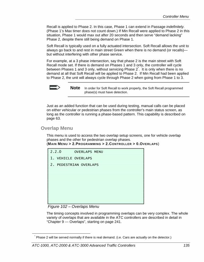
Controller Menu
ATC-1000, ATC-2000 & ATC-3000 Advanced Traffic Controllers 135
Recall is applied to Phase 2. In this case, Phase 1 can extend in Passage indefinitely. (Phase 1’s Max timer does not count down.) If Min Recall were applied to Phase 2 in this situation, Phase 1 would max out after 20 seconds and then serve “demand lacking” Phase 2, despite there still being demand on Phase 1.
Soft Recall is typically used on a fully actuated intersection. Soft Recall allows the unit to always go back to and rest in main street Green when there is no demand (or recalls)—but without interfering with other phase service.
For example, at a 3 phase intersection, say that phase 2 is the main street with Soft Recall mode set. If there is demand on Phases 1 and 3 only, the controller will cycle between Phases 1 and 3 only, without servicing Phase 2*. It is only when there is no demand at all that Soft Recall will be applied to Phase 2. If Min Recall had been applied to Phase 2, the unit will always cycle through Phase 2 when going from Phase 1 to 3.
Note In order for Soft Recall to work properly, the Soft Recall programmed phase(s) must have detection.
Just as an added function that can be used during testing, manual calls can be placed on either vehicular or pedestrian phases from the controller’s main status screen, as long as the controller is running a phase-based pattern. This capability is described on page 63.
Overlap Menu This menu is used to access the two overlap setup screens, one for vehicle overlap phases and the other for pedestrian overlap phases. (MAIN MENU > 2.PROGRAMMING > 2.CONTROLLER > 0.OVERLAPS)
2.2.0 OVERLAPS MENU 1. VEHICLE OVERLAPS 2. PEDESTRIAN OVERLAPS
Figure 102 – Overlaps Menu The timing concepts involved in programming overlaps can be very complex. The whole variety of overlaps that are available in the ATC controllers are described in detail in “Chapter 9 — Overlaps”, starting on page 241.
* Phase 2 will be served normally if there is real demand. (i.e. Cars are actually on the detector.)
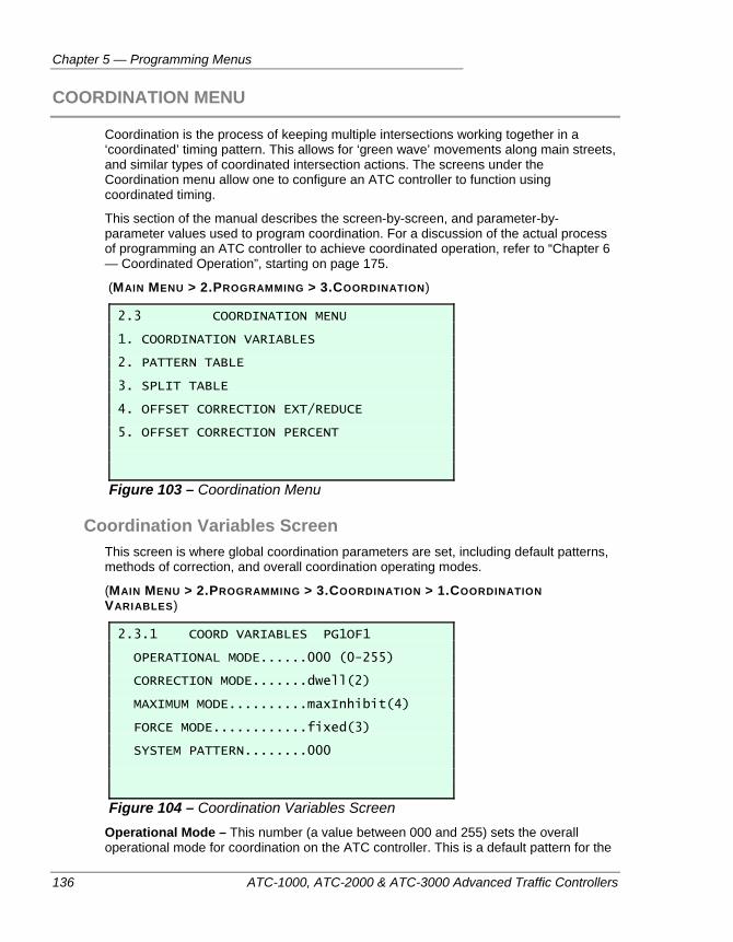
Chapter 5 — Programming Menus
136 ATC-1000, ATC-2000 & ATC-3000 Advanced Traffic Controllers
COORDINATION MENU
Coordination is the process of keeping multiple intersections working together in a ‘coordinated’ timing pattern. This allows for ‘green wave’ movements along main streets, and similar types of coordinated intersection actions. The screens under the Coordination menu allow one to configure an ATC controller to function using coordinated timing.
This section of the manual describes the screen-by-screen, and parameter-by-parameter values used to program coordination. For a discussion of the actual process of programming an ATC controller to achieve coordinated operation, refer to “Chapter 6 — Coordinated Operation”, starting on page 175.
(MAIN MENU > 2.PROGRAMMING > 3.COORDINATION)
2.3 COORDINATION MENU 1. COORDINATION VARIABLES 2. PATTERN TABLE 3. SPLIT TABLE 4. OFFSET CORRECTION EXT/REDUCE 5. OFFSET CORRECTION PERCENT
Figure 103 – Coordination Menu
Coordination Variables Screen This screen is where global coordination parameters are set, including default patterns, methods of correction, and overall coordination operating modes.
(MAIN MENU > 2.PROGRAMMING > 3.COORDINATION > 1.COORDINATION VARIABLES)
2.3.1 COORD VARIABLES PG1OF1 OPERATIONAL MODE......000 (0-255) CORRECTION MODE.......dwell(2) MAXIMUM MODE..........maxInhibit(4) FORCE MODE............fixed(3) SYSTEM PATTERN........000
Figure 104 – Coordination Variables Screen
Operational Mode – This number (a value between 000 and 255) sets the overall operational mode for coordination on the ATC controller. This is a default pattern for the
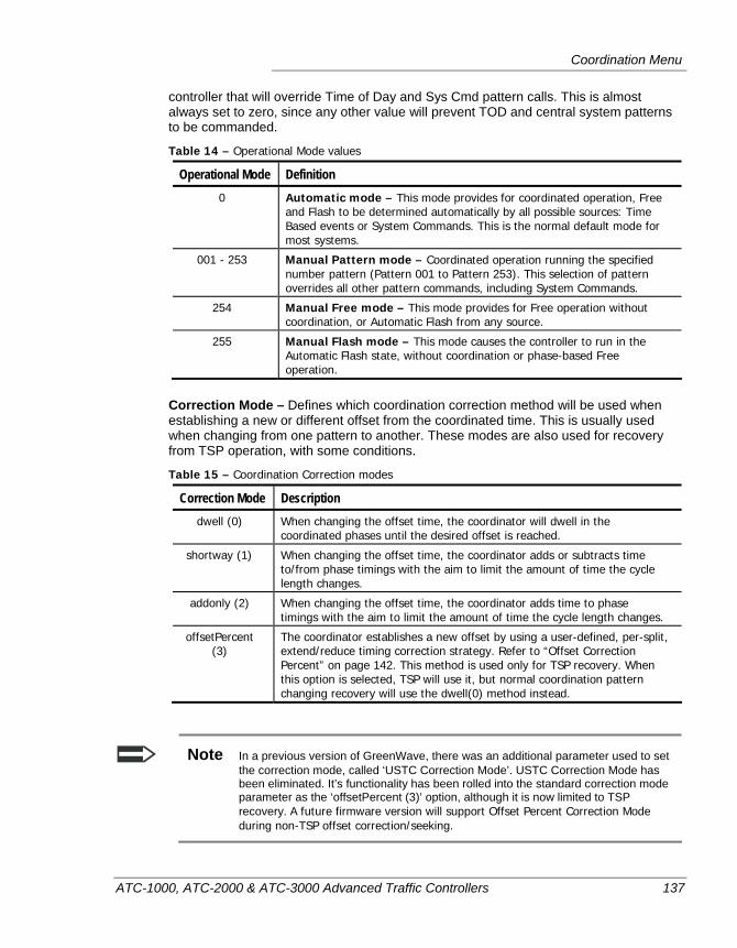
Coordination Menu
ATC-1000, ATC-2000 & ATC-3000 Advanced Traffic Controllers 137
controller that will override Time of Day and Sys Cmd pattern calls. This is almost always set to zero, since any other value will prevent TOD and central system patterns to be commanded.
Table 14 – Operational Mode values
Operational Mode Definition 0 Automatic mode – This mode provides for coordinated operation, Free
and Flash to be determined automatically by all possible sources: Time Based events or System Commands. This is the normal default mode for most systems.
001 - 253 Manual Pattern mode – Coordinated operation running the specified number pattern (Pattern 001 to Pattern 253). This selection of pattern overrides all other pattern commands, including System Commands.
254 Manual Free mode – This mode provides for Free operation without coordination, or Automatic Flash from any source.
255 Manual Flash mode – This mode causes the controller to run in the Automatic Flash state, without coordination or phase-based Free operation.
Correction Mode – Defines which coordination correction method will be used when establishing a new or different offset from the coordinated time. This is usually used when changing from one pattern to another. These modes are also used for recovery from TSP operation, with some conditions.
Table 15 – Coordination Correction modes
Correction Mode Description dwell (0) When changing the offset time, the coordinator will dwell in the
coordinated phases until the desired offset is reached.
shortway (1) When changing the offset time, the coordinator adds or subtracts time to/from phase timings with the aim to limit the amount of time the cycle length changes.
addonly (2) When changing the offset time, the coordinator adds time to phase timings with the aim to limit the amount of time the cycle length changes.
offsetPercent (3)
The coordinator establishes a new offset by using a user-defined, per-split, extend/reduce timing correction strategy. Refer to “Offset Correction Percent” on page 142. This method is used only for TSP recovery. When this option is selected, TSP will use it, but normal coordination pattern changing recovery will use the dwell(0) method instead.
Note In a previous version of GreenWave, there was an additional parameter used to set the correction mode, called ‘USTC Correction Mode’. USTC Correction Mode has been eliminated. It’s functionality has been rolled into the standard correction mode parameter as the ‘offsetPercent (3)’ option, although it is now limited to TSP recovery. A future firmware version will support Offset Percent Correction Mode during non-TSP offset correction/seeking.
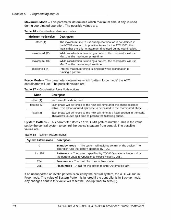
Chapter 5 — Programming Menus
138 ATC-1000, ATC-2000 & ATC-3000 Advanced Traffic Controllers
Maximum Mode – This parameter determines which maximum time, if any, is used during coordinated operation. The possible values are:
Table 16 – Coordination Maximum modes
Maximum mode value Description other (1) The maximum time to use during coordination is not defined in
the NTCIP standard. In practical terms for the ATC-1000, this means that there is no maximum time used during coordination.
maximum1 (2) While coordination is running a pattern, the coordinator will use Max 1 as the maximum phase time.
maximum2 (3) While coordination is running a pattern, the coordinator will use Max 2 as the maximum phase time.
maxInhibit (4) Internal maximum timing is inhibited while coordination is running a pattern.
Force Mode – This parameter determines which ‘pattern force mode’ the ATC coordinator will use. The possible values are:
Table 17 – Coordination Force Mode options
Mode Description other (1) No force off mode is used.
floating (2) Each phase will be forced to the new split time after the phase becomes active. This allows unused split time to be passed to the coordinated phase.
fixed (3) Each phase will be forced to the new split time at a fixed position in the cycle. This allows unused split time to pass to the following phase.
System Pattern – This parameter stores a SYS CMD pattern number. This is the value set by the central system to control the device’s pattern from central. The possible values are:
Table 18 – System Pattern modes
System Pattern mode Description 0 Standby mode – The system relinquishes control of the device. The
controller runs the pattern specified by TOD.
1 - 253 Pattern # – The pattern specified by TOD if Operational Mode = 0 or the pattern equal to Operational Mode's value (1-255).
254 Free mode – The controller runs in Free mode.
255 Flash mode – A call for the device to enter Automatic Flash.
If an unsupported or invalid pattern is called by the central system, the ATC will run in Free mode. The value of System Pattern is ignored if the controller is in Backup mode. Any changes sent to this value will reset the Backup timer to zero (0).
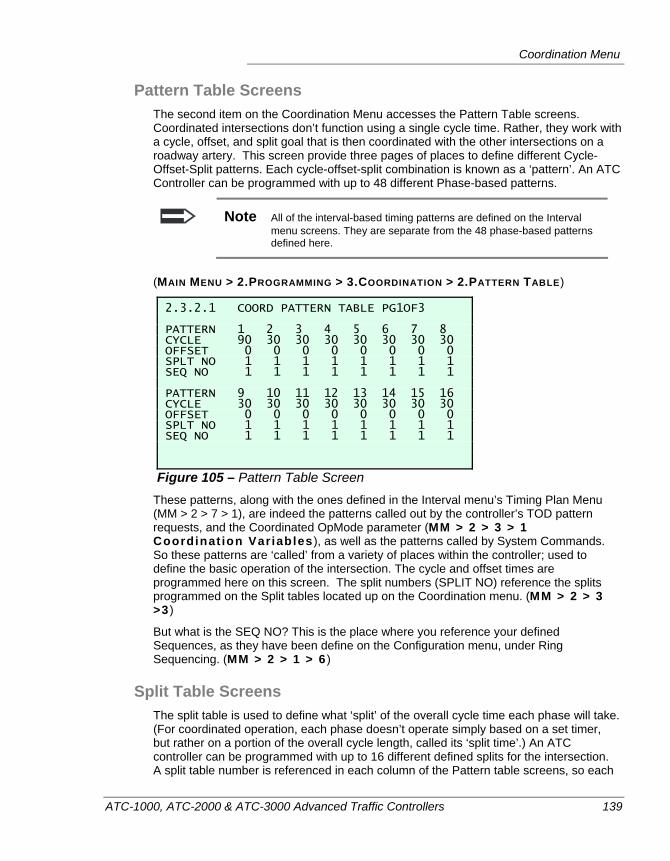
Coordination Menu
ATC-1000, ATC-2000 & ATC-3000 Advanced Traffic Controllers 139
Pattern Table Screens The second item on the Coordination Menu accesses the Pattern Table screens. Coordinated intersections don’t function using a single cycle time. Rather, they work with a cycle, offset, and split goal that is then coordinated with the other intersections on a roadway artery. This screen provide three pages of places to define different Cycle-Offset-Split patterns. Each cycle-offset-split combination is known as a ‘pattern’. An ATC Controller can be programmed with up to 48 different Phase-based patterns.
Note All of the interval-based timing patterns are defined on the Interval menu screens. They are separate from the 48 phase-based patterns defined here.
(MAIN MENU > 2.PROGRAMMING > 3.COORDINATION > 2.PATTERN TABLE)
2.3.2.1 COORD PATTERN TABLE PG1OF3 PATTERN 1 2 3 4 5 6 7 8 CYCLE 90 30 30 30 30 30 30 30 OFFSET 0 0 0 0 0 0 0 0 SPLT NO 1 1 1 1 1 1 1 1 SEQ NO 1 1 1 1 1 1 1 1 PATTERN 9 10 11 12 13 14 15 16 CYCLE 30 30 30 30 30 30 30 30 OFFSET 0 0 0 0 0 0 0 0 SPLT NO 1 1 1 1 1 1 1 1 SEQ NO 1 1 1 1 1 1 1 1
Figure 105 – Pattern Table Screen These patterns, along with the ones defined in the Interval menu’s Timing Plan Menu (MM > 2 > 7 > 1), are indeed the patterns called out by the controller’s TOD pattern requests, and the Coordinated OpMode parameter (MM > 2 > 3 > 1 Coordinat ion Variables ), as well as the patterns called by System Commands. So these patterns are ‘called’ from a variety of places within the controller; used to define the basic operation of the intersection. The cycle and offset times are programmed here on this screen. The split numbers (SPLIT NO) reference the splits programmed on the Split tables located up on the Coordination menu. (MM > 2 > 3 >3 )
But what is the SEQ NO? This is the place where you reference your defined Sequences, as they have been define on the Configuration menu, under Ring Sequencing. (MM > 2 > 1 > 6 )
Split Table Screens The split table is used to define what ‘split’ of the overall cycle time each phase will take. (For coordinated operation, each phase doesn’t operate simply based on a set timer, but rather on a portion of the overall cycle length, called its ‘split time’.) An ATC controller can be programmed with up to 16 different defined splits for the intersection. A split table number is referenced in each column of the Pattern table screens, so each
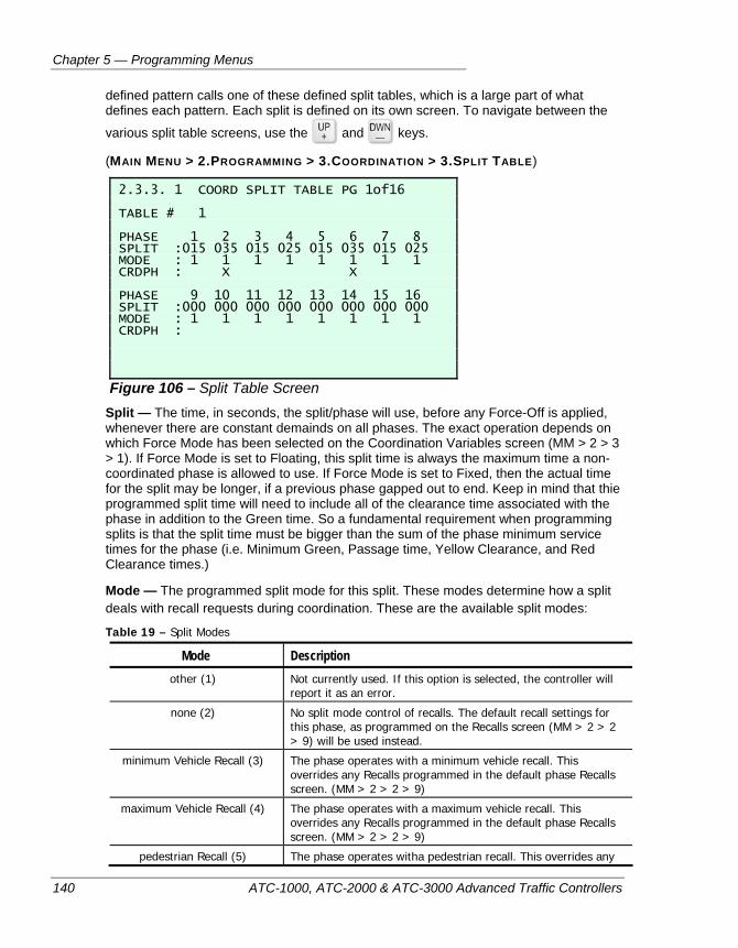
Chapter 5 — Programming Menus
140 ATC-1000, ATC-2000 & ATC-3000 Advanced Traffic Controllers
defined pattern calls one of these defined split tables, which is a large part of what defines each pattern. Each split is defined on its own screen. To navigate between the
various split table screens, use the and keys.
(MAIN MENU > 2.PROGRAMMING > 3.COORDINATION > 3.SPLIT TABLE)
2.3.3. 1 COORD SPLIT TABLE PG 1of16 TABLE # 1 PHASE 1 2 3 4 5 6 7 8 SPLIT :015 035 015 025 015 035 015 025 MODE : 1 1 1 1 1 1 1 1 CRDPH : X X PHASE 9 10 11 12 13 14 15 16 SPLIT :000 000 000 000 000 000 000 000 MODE : 1 1 1 1 1 1 1 1 CRDPH :
Figure 106 – Split Table Screen Split — The time, in seconds, the split/phase will use, before any Force-Off is applied, whenever there are constant demainds on all phases. The exact operation depends on which Force Mode has been selected on the Coordination Variables screen (MM > 2 > 3 > 1). If Force Mode is set to Floating, this split time is always the maximum time a non-coordinated phase is allowed to use. If Force Mode is set to Fixed, then the actual time for the split may be longer, if a previous phase gapped out to end. Keep in mind that thie programmed split time will need to include all of the clearance time associated with the phase in addition to the Green time. So a fundamental requirement when programming splits is that the split time must be bigger than the sum of the phase minimum service times for the phase (i.e. Minimum Green, Passage time, Yellow Clearance, and Red Clearance times.)
Mode — The programmed split mode for this split. These modes determine how a split deals with recall requests during coordination. These are the available split modes:
Table 19 – Split Modes
Mode Description other (1) Not currently used. If this option is selected, the controller will
report it as an error.
none (2) No split mode control of recalls. The default recall settings for this phase, as programmed on the Recalls screen (MM > 2 > 2 > 9) will be used instead.
minimum Vehicle Recall (3) The phase operates with a minimum vehicle recall. This overrides any Recalls programmed in the default phase Recalls screen. (MM > 2 > 2 > 9)
maximum Vehicle Recall (4) The phase operates with a maximum vehicle recall. This overrides any Recalls programmed in the default phase Recalls screen. (MM > 2 > 2 > 9)
pedestrian Recall (5) The phase operates witha pedestrian recall. This overrides any
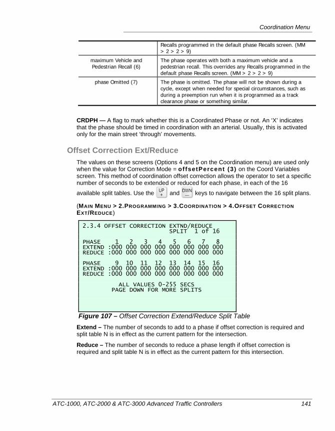
Coordination Menu
ATC-1000, ATC-2000 & ATC-3000 Advanced Traffic Controllers 141
Recalls programmed in the default phase Recalls screen. (MM > 2 > 2 > 9)
maximum Vehicle and Pedestrian Recall (6)
The phase operates with both a maximum vehicle and a pedestrian recall. This overrides any Recalls programmed in the default phase Recalls screen. (MM > 2 > 2 > 9)
phase Omitted (7) The phase is omitted. The phase will not be shown during a cycle, except when needed for special circumstances, such as during a preemption run when it is programmed as a track clearance phase or something similar.
CRDPH — A flag to mark whether this is a Coordinated Phase or not. An ‘X’ indicates that the phase should be timed in coordination with an arterial. Usually, this is activated only for the main street ‘through’ movements.
Offset Correction Ext/Reduce The values on these screens (Options 4 and 5 on the Coordination menu) are used only when the value for Correction Mode = offsetPercent (3) on the Coord Variables screen. This method of coordination offset correction allows the operator to set a specific number of seconds to be extended or reduced for each phase, in each of the 16
available split tables. Use the and keys to navigate between the 16 split plans.
(MAIN MENU > 2.PROGRAMMING > 3.COORDINATION > 4.OFFSET CORRECTION EXT/REDUCE)
2.3.4 OFFSET CORRECTION EXTND/REDUCE SPLIT 1 of 16 PHASE 1 2 3 4 5 6 7 8 EXTEND :000 000 000 000 000 000 000 000 REDUCE :000 000 000 000 000 000 000 000 PHASE 9 10 11 12 13 14 15 16 EXTEND :000 000 000 000 000 000 000 000 REDUCE :000 000 000 000 000 000 000 000 ALL VALUES 0-255 SECS PAGE DOWN FOR MORE SPLITS
Figure 107 – Offset Correction Extend/Reduce Split Table Extend – The number of seconds to add to a phase if offset correction is required and split table N is in effect as the current pattern for the intersection.
Reduce – The number of seconds to reduce a phase length if offset correction is required and split table N is in effect as the current pattern for this intersection.
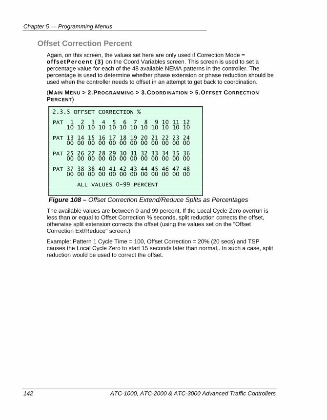
Chapter 5 — Programming Menus
142 ATC-1000, ATC-2000 & ATC-3000 Advanced Traffic Controllers
Offset Correction Percent Again, on this screen, the values set here are only used if Correction Mode = offsetPercent (3) on the Coord Variables screen. This screen is used to set a percentage value for each of the 48 available NEMA patterns in the controller. The percentage is used to determine whether phase extension or phase reduction should be used when the controller needs to offset in an attempt to get back to coordination.
(MAIN MENU > 2.PROGRAMMING > 3.COORDINATION > 5.OFFSET CORRECTION PERCENT)
2.3.5 OFFSET CORRECTION % PAT 1 2 3 4 5 6 7 8 9 10 11 12 10 10 10 10 10 10 10 10 10 10 10 10 PAT 13 14 15 16 17 18 19 20 21 22 23 24 00 00 00 00 00 00 00 00 00 00 00 00 PAT 25 26 27 28 29 30 31 32 33 34 35 36 00 00 00 00 00 00 00 00 00 00 00 00 PAT 37 38 38 40 41 42 43 44 45 46 47 48 00 00 00 00 00 00 00 00 00 00 00 00 ALL VALUES 0-99 PERCENT
Figure 108 – Offset Correction Extend/Reduce Splits as Percentages The available values are between 0 and 99 percent, If the Local Cycle Zero overrun is less than or equal to Offset Correction % seconds, split reduction corrects the offset, otherwise split extension corrects the offset (using the values set on the "Offset Correction Ext/Reduce" screen.)
Example: Pattern 1 Cycle Time = 100, Offset Correction = 20% (20 secs) and TSP causes the Local Cycle Zero to start 15 seconds later than normal,. In such a case, split reduction would be used to correct the offset.
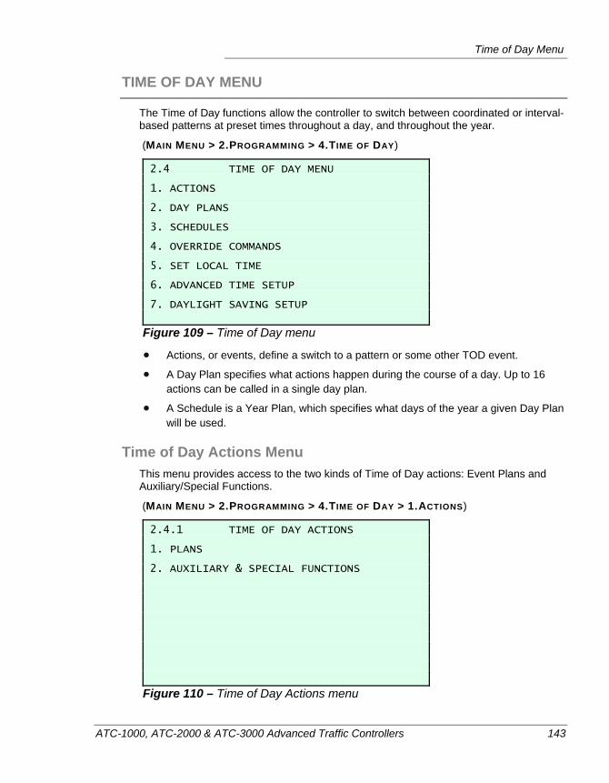
Time of Day Menu
ATC-1000, ATC-2000 & ATC-3000 Advanced Traffic Controllers 143
TIME OF DAY MENU
The Time of Day functions allow the controller to switch between coordinated or interval-based patterns at preset times throughout a day, and throughout the year.
(MAIN MENU > 2.PROGRAMMING > 4.TIME OF DAY)
2.4 TIME OF DAY MENU 1. ACTIONS 2. DAY PLANS 3. SCHEDULES 4. OVERRIDE COMMANDS 5. SET LOCAL TIME 6. ADVANCED TIME SETUP 7. DAYLIGHT SAVING SETUP
Figure 109 – Time of Day menu
Actions, or events, define a switch to a pattern or some other TOD event.
A Day Plan specifies what actions happen during the course of a day. Up to 16 actions can be called in a single day plan.
A Schedule is a Year Plan, which specifies what days of the year a given Day Plan will be used.
Time of Day Actions Menu This menu provides access to the two kinds of Time of Day actions: Event Plans and Auxiliary/Special Functions.
(MAIN MENU > 2.PROGRAMMING > 4.TIME OF DAY > 1.ACTIONS)
2.4.1 TIME OF DAY ACTIONS 1. PLANS 2. AUXILIARY & SPECIAL FUNCTIONS
Figure 110 – Time of Day Actions menu
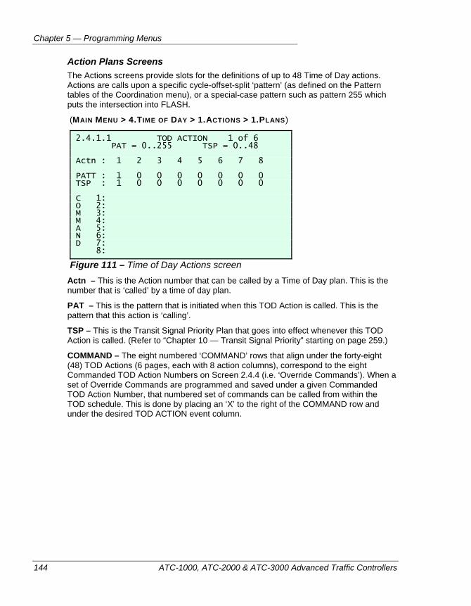
Chapter 5 — Programming Menus
144 ATC-1000, ATC-2000 & ATC-3000 Advanced Traffic Controllers
Action Plans Screens The Actions screens provide slots for the definitions of up to 48 Time of Day actions. Actions are calls upon a specific cycle-offset-split ‘pattern’ (as defined on the Pattern tables of the Coordination menu), or a special-case pattern such as pattern 255 which puts the intersection into FLASH.
(MAIN MENU > 4.TIME OF DAY > 1.ACTIONS > 1.PLANS)
2.4.1.1 TOD ACTION 1 of 6 PAT = 0..255 TSP = 0..48 Actn : 1 2 3 4 5 6 7 8 PATT : 1 0 0 0 0 0 0 0 TSP : 1 0 0 0 0 0 0 0 C 1: O 2: M 3: M 4: A 5: N 6: D 7: 8:
Figure 111 – Time of Day Actions screen Actn – This is the Action number that can be called by a Time of Day plan. This is the number that is ‘called’ by a time of day plan.
PAT – This is the pattern that is initiated when this TOD Action is called. This is the pattern that this action is ‘calling’.
TSP – This is the Transit Signal Priority Plan that goes into effect whenever this TOD Action is called. (Refer to “Chapter 10 — Transit Signal Priority” starting on page 259.)
COMMAND – The eight numbered ‘COMMAND’ rows that align under the forty-eight (48) TOD Actions (6 pages, each with 8 action columns), correspond to the eight Commanded TOD Action Numbers on Screen 2.4.4 (i.e. ‘Override Commands’). When a set of Override Commands are programmed and saved under a given Commanded TOD Action Number, that numbered set of commands can be called from within the TOD schedule. This is done by placing an ‘X’ to the right of the COMMAND row and under the desired TOD ACTION event column.
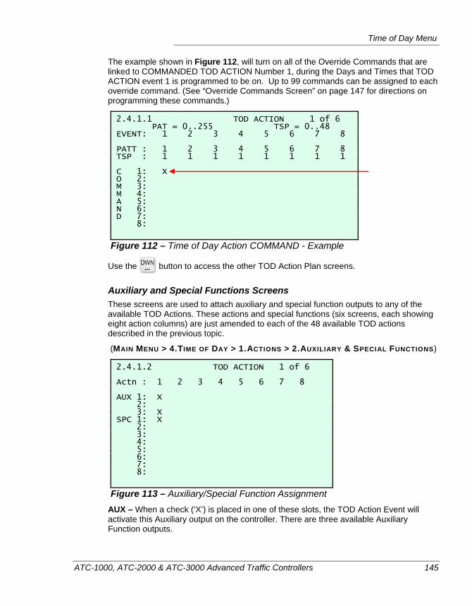
Time of Day Menu
ATC-1000, ATC-2000 & ATC-3000 Advanced Traffic Controllers 145
The example shown in Figure 112, will turn on all of the Override Commands that are linked to COMMANDED TOD ACTION Number 1, during the Days and Times that TOD ACTION event 1 is programmed to be on. Up to 99 commands can be assigned to each override command. (See “Override Commands Screen” on page 147 for directions on programming these commands.)
2.4.1.1 TOD ACTION 1 of 6 PAT = 0..255 TSP = 0..48 EVENT: 1 2 3 4 5 6 7 8 PATT : 1 2 3 4 5 6 7 8 TSP : 1 1 1 1 1 1 1 1 C 1: X O 2: M 3: M 4: A 5: N 6: D 7: 8:
Figure 112 – Time of Day Action COMMAND - Example
Use the button to access the other TOD Action Plan screens.
Auxiliary and Special Functions Screens These screens are used to attach auxiliary and special function outputs to any of the available TOD Actions. These actions and special functions (six screens, each showing eight action columns) are just amended to each of the 48 available TOD actions described in the previous topic.
(MAIN MENU > 4.TIME OF DAY > 1.ACTIONS > 2.AUXILIARY & SPECIAL FUNCTIONS)
2.4.1.2 TOD ACTION 1 of 6 Actn : 1 2 3 4 5 6 7 8 AUX 1: X 2: 3: X SPC 1: X 2: 3: 4: 5: 6: 7: 8:
Figure 113 – Auxiliary/Special Function Assignment AUX – When a check (‘X’) is placed in one of these slots, the TOD Action Event will activate this Auxiliary output on the controller. There are three available Auxiliary Function outputs.
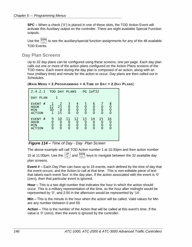
Chapter 5 — Programming Menus
146 ATC-1000, ATC-2000 & ATC-3000 Advanced Traffic Controllers
SPC – When a check (‘X’) is placed in one of these slots, the TOD Action Event will activate this Auxiliary output on the controller. There are eight available Special Function outputs.
Use the to see the auxiliary/special function assignments for any of the 48 available TOD Events.
Day Plan Screens Up to 32 day plans can be configured using these screens, one per page. Each day plan calls out one or more of the action plans configured on the Action Plans screens of the TOD menu. Each event during the day plan is composed of an action, along with an hour (military time) and minute for the action to occur. Day plans are then called out in Schedules.
(MAIN MENU > 2.PROGRAMMING > 4.TIME OF DAY > 2.DAY PLANS)
2.4.2.1 TOD DAY PLANS PG 1of32 DAY PLAN 1 EVENT # 1 2 3 4 5 6 7 8 HOUR 22 23 0 0 0 0 0 0 MIN 30 0 0 0 0 0 0 0 ACTION 1 15 0 0 0 0 0 0 EVENT # 9 10 11 12 13 14 15 16 HOUR 0 0 0 0 0 0 0 0 MIN 0 0 0 0 0 0 0 0 ACTION 0 0 0 0 0 0 0 0
Figure 114 – Time of Day - Day Plan Screen The above example will call TOD Action number 1 at 10:30pm and then action number
15 at 11:00pm. Use the and keys to navigate between the 32 available day plan screens.
Event # – Each Day Plan can have up to 16 events, each defined by the time of day that the event occurs, and the Action to call at that time. This is non-editable piece of text that labels each event ‘box’ in the day plan. If the action associated with the event is ‘0’ (zero), then that particular event is ignored.
Hour – This is a two digit number that indicates the hour in which the action should occur. This is a military representation of the time, so the hour after midnight would be represented by ‘0’, and 2:00 in the afternoon would be represented by ‘14’.
Min – This is the minute in the hour when the action will be called. Valid values for Min are any number between 0 and 59.
Action – This is the number of the Action that will be called at this event’s time. If the value is ‘0’ (zero), then the event is ignored by the controller.
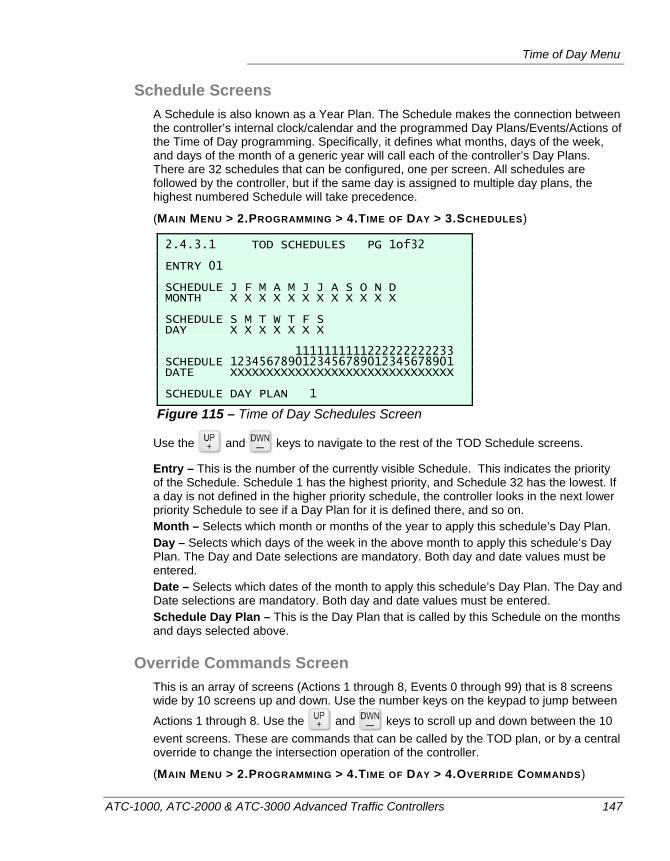
Time of Day Menu
ATC-1000, ATC-2000 & ATC-3000 Advanced Traffic Controllers 147
Schedule Screens A Schedule is also known as a Year Plan. The Schedule makes the connection between the controller’s internal clock/calendar and the programmed Day Plans/Events/Actions of the Time of Day programming. Specifically, it defines what months, days of the week, and days of the month of a generic year will call each of the controller’s Day Plans. There are 32 schedules that can be configured, one per screen. All schedules are followed by the controller, but if the same day is assigned to multiple day plans, the highest numbered Schedule will take precedence.
(MAIN MENU > 2.PROGRAMMING > 4.TIME OF DAY > 3.SCHEDULES)
2.4.3.1 TOD SCHEDULES PG 1of32 ENTRY 01 SCHEDULE J F M A M J J A S O N D MONTH X X X X X X X X X X X X SCHEDULE S M T W T F S DAY X X X X X X X 1111111111222222222233 SCHEDULE 1234567890123456789012345678901 DATE XXXXXXXXXXXXXXXXXXXXXXXXXXXXXXX SCHEDULE DAY PLAN 1
Figure 115 – Time of Day Schedules Screen
Use the and keys to navigate to the rest of the TOD Schedule screens.
Entry – This is the number of the currently visible Schedule. This indicates the priority of the Schedule. Schedule 1 has the highest priority, and Schedule 32 has the lowest. If a day is not defined in the higher priority schedule, the controller looks in the next lower priority Schedule to see if a Day Plan for it is defined there, and so on. Month – Selects which month or months of the year to apply this schedule’s Day Plan. Day – Selects which days of the week in the above month to apply this schedule’s Day Plan. The Day and Date selections are mandatory. Both day and date values must be entered. Date – Selects which dates of the month to apply this schedule’s Day Plan. The Day and Date selections are mandatory. Both day and date values must be entered. Schedule Day Plan – This is the Day Plan that is called by this Schedule on the months and days selected above.
Override Commands Screen This is an array of screens (Actions 1 through 8, Events 0 through 99) that is 8 screens wide by 10 screens up and down. Use the number keys on the keypad to jump between
Actions 1 through 8. Use the and keys to scroll up and down between the 10 event screens. These are commands that can be called by the TOD plan, or by a central override to change the intersection operation of the controller.
(MAIN MENU > 2.PROGRAMMING > 4.TIME OF DAY > 4.OVERRIDE COMMANDS)
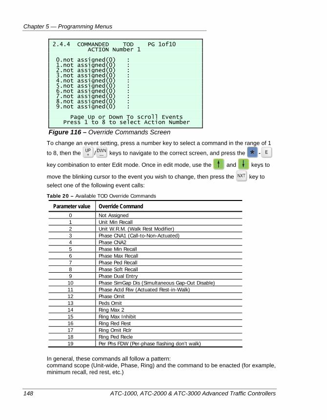
Chapter 5 — Programming Menus
148 ATC-1000, ATC-2000 & ATC-3000 Advanced Traffic Controllers
2.4.4 COMMANDED TOD PG 1of10 ACTION Number 1 0.not assigned(0) : 1.not assigned(0) : 2.not assigned(0) : 3.not assigned(0) : 4.not assigned(0) : 5.not assigned(0) : 6.not assigned(0) : 7.not assigned(0) : 8.not assigned(0) : 9.not assigned(0) : Page Up or Down To scroll Events Press 1 to 8 to select Action Number
Figure 116 – Override Commands Screen To change an event setting, press a number key to select a command in the range of 1
to 8, then the / keys to navigate to the correct screen, and press the -
key combination to enter Edit mode. Once in edit mode, use the and keys to
move the blinking cursor to the event you wish to change, then press the key to select one of the following event calls:
Table 20 – Available TOD Override Commands
Parameter value Override Command 0 Not Assigned 1 Unit Min Recall 2 Unit W.R.M. (Walk Rest Modifier) 3 Phase CNA1 (Call-to-Non-Actuated) 4 Phase CNA2 5 Phase Min Recall 6 Phase Max Recall 7 Phase Ped Recall 8 Phase Soft Recall 9 Phase Dual Entry 10 Phase SimGap Dis (Simultaneous Gap-Out Disable) 11 Phase Actd Riw (Actuated Rest-in-Walk) 12 Phase Omit 13 Peds Omit 14 Ring Max 2 15 Ring Max Inhibit 16 Ring Red Rest 17 Ring Omit Rclr 18 Ring Ped Recle 19 Per Phs FDW (Per-phase flashing don’t walk)
In general, these commands all follow a pattern: command scope (Unit-wide, Phase, Ring) and the command to be enacted (for example, minimum recall, red rest, etc.)
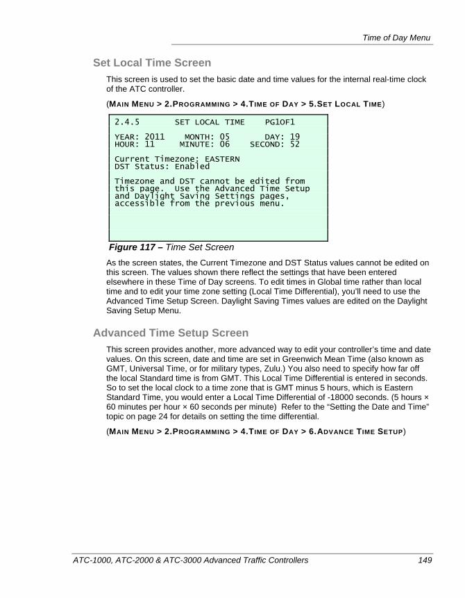
Time of Day Menu
ATC-1000, ATC-2000 & ATC-3000 Advanced Traffic Controllers 149
Set Local Time Screen This screen is used to set the basic date and time values for the internal real-time clock of the ATC controller.
(MAIN MENU > 2.PROGRAMMING > 4.TIME OF DAY > 5.SET LOCAL TIME)
2.4.5 SET LOCAL TIME PG1OF1 YEAR: 2011 MONTH: 05 DAY: 19 HOUR: 11 MINUTE: 06 SECOND: 52 Current Timezone: EASTERN DST Status: Enabled Timezone and DST cannot be edited from this page. Use the Advanced Time Setup and Daylight Saving Settings pages, accessible from the previous menu.
Figure 117 – Time Set Screen As the screen states, the Current Timezone and DST Status values cannot be edited on this screen. The values shown there reflect the settings that have been entered elsewhere in these Time of Day screens. To edit times in Global time rather than local time and to edit your time zone setting (Local Time Differential), you’ll need to use the Advanced Time Setup Screen. Daylight Saving Times values are edited on the Daylight Saving Setup Menu.
Advanced Time Setup Screen This screen provides another, more advanced way to edit your controller’s time and date values. On this screen, date and time are set in Greenwich Mean Time (also known as GMT, Universal Time, or for military types, Zulu.) You also need to specify how far off the local Standard time is from GMT. This Local Time Differential is entered in seconds. So to set the local clock to a time zone that is GMT minus 5 hours, which is Eastern Standard Time, you would enter a Local Time Differential of -18000 seconds. (5 hours × 60 minutes per hour × 60 seconds per minute) Refer to the “Setting the Date and Time” topic on page 24 for details on setting the time differential.
(MAIN MENU > 2.PROGRAMMING > 4.TIME OF DAY > 6.ADVANCE TIME SETUP)
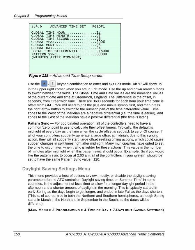
Chapter 5 — Programming Menus
150 ATC-1000, ATC-2000 & ATC-3000 Advanced Traffic Controllers
2.4.6 ADVANCED TIME SET PG1OF1 GLOBAL TIME HOUR...............12 GLOBAL TIME MINUTE.............07 GLOBAL TIME SECOND.............06 GLOBAL YEAR....................2006 GLOBAL MONTH...................03 GLOBAL DAY.....................24 LOCAL TIME DIFFERENTIAL........-18000 PATTERN SYNC...................00000 (MINUTES AFTER MIDNIGHT)
Figure 118 – Advanced Time Setup screen
Use the - keypad combination to enter and exit Edit mode. An ‘E’ will show up in the upper right corner when you are in Edit mode. Use the up and down arrow buttons to switch between the fields. The Global Time and Date values are the numerical values of the current date and time at Greenwich, England. The Differential is the offset, in seconds, from Greenwich time. There are 3600 seconds for each hour your time zone is offset from GMT. You will need to edit the plus and minus symbol first, and then press the right arrow button to switch to the numeric part of the time differential value. Time zones to the West of the Meridian are a negative differential (i.e. the time is earlier), and zones to the East of the Meridian have a positive differential (the time is later.)
Pattern Sync — For coordinated operation, all of the controllers need to have a common ‘zero’ point to use to calculate their offset timers. Typically, the default is midnight of every day as the time when the cycle offset is set back to zero. Of course, if all of your controllers suddenly generate a large offset at midnight due to this syncing action, they will all suddenly start large offset seeking timing actions, which could cause sudden changes in split times right after midnight. Many municipalities have opted to set the time to occur later, when traffic is lighter for these actions. This value is the number of minutes after midnight when this pattern sync should occur. Example: So if you would like the pattern sync to occur at 2:00 am, all of the controllers in your system should be set to have the same Pattern Sync value: 120.
Daylight Saving Settings Menu This menu provides a host of options to view, modify, or disable the daylight saving parameters for the ATC controller. Daylight saving time, or ‘Summer Time’ in some countries, is the adjustment of local time to allow for a longer daylight period in the afternoon and a shorter amount of daylight in the morning. This is typically started in early Spring as the days begin to get longer, and ended in late Fall as the days shorten. (This is, of course, true in both the Northern and Southern hemispheres, although Spring starts in March in the North and in September in the South, so the dates will be different.)
(MAIN MENU > 2.PROGRAMMING > 4.TIME OF DAY > 7.DAYLIGHT SAVING SETTINGS)
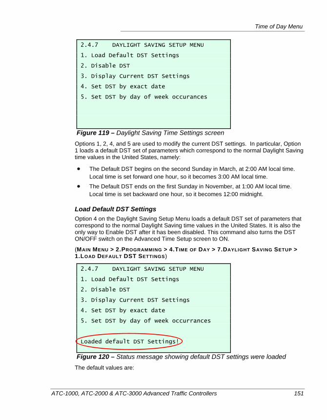
Time of Day Menu
ATC-1000, ATC-2000 & ATC-3000 Advanced Traffic Controllers 151
2.4.7 DAYLIGHT SAVING SETUP MENU 1. Load Default DST Settings 2. Disable DST 3. Display Current DST Settings 4. Set DST by exact date 5. Set DST by day of week occurances
Figure 119 – Daylight Saving Time Settings screen Options 1, 2, 4, and 5 are used to modify the current DST settings. In particular, Option 1 loads a default DST set of parameters which correspond to the normal Daylight Saving time values in the United States, namely:
The Default DST begins on the second Sunday in March, at 2:00 AM local time. Local time is set forward one hour, so it becomes 3:00 AM local time.
The Default DST ends on the first Sunday in November, at 1:00 AM local time. Local time is set backward one hour, so it becomes 12:00 midnight.
Load Default DST Settings Option 4 on the Daylight Saving Setup Menu loads a default DST set of parameters that correspond to the normal Daylight Saving time values in the United States. It is also the only way to Enable DST after it has been disabled. This command also turns the DST ON/OFF switch on the Advanced Time Setup screen to ON.
(MAIN MENU > 2.PROGRAMMING > 4.TIME OF DAY > 7.DAYLIGHT SAVING SETUP > 1.LOAD DEFAULT DST SETTINGS)
2.4.7 DAYLIGHT SAVING SETUP MENU 1. Load Default DST Settings 2. Disable DST 3. Display Current DST Settings 4. Set DST by exact date 5. Set DST by day of week occurrances Loaded default DST Settings!
Figure 120 – Status message showing default DST settings were loaded The default values are:
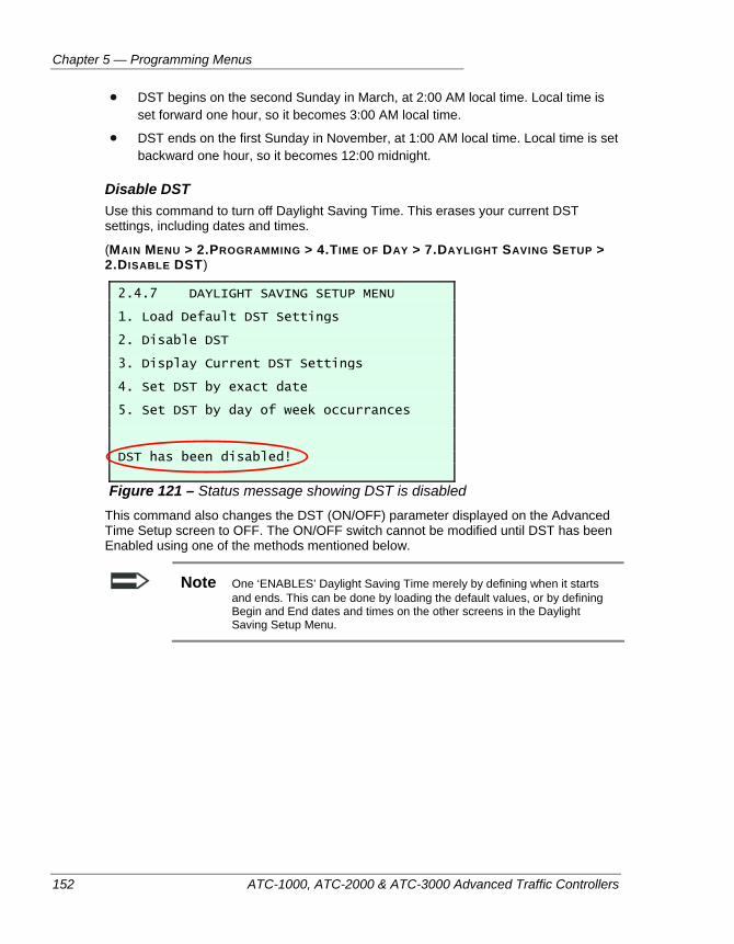
Chapter 5 — Programming Menus
152 ATC-1000, ATC-2000 & ATC-3000 Advanced Traffic Controllers
DST begins on the second Sunday in March, at 2:00 AM local time. Local time is set forward one hour, so it becomes 3:00 AM local time.
DST ends on the first Sunday in November, at 1:00 AM local time. Local time is set backward one hour, so it becomes 12:00 midnight.
Disable DST Use this command to turn off Daylight Saving Time. This erases your current DST settings, including dates and times.
(MAIN MENU > 2.PROGRAMMING > 4.TIME OF DAY > 7.DAYLIGHT SAVING SETUP > 2.DISABLE DST)
2.4.7 DAYLIGHT SAVING SETUP MENU 1. Load Default DST Settings 2. Disable DST 3. Display Current DST Settings 4. Set DST by exact date 5. Set DST by day of week occurrances DST has been disabled!
Figure 121 – Status message showing DST is disabled This command also changes the DST (ON/OFF) parameter displayed on the Advanced Time Setup screen to OFF. The ON/OFF switch cannot be modified until DST has been Enabled using one of the methods mentioned below.
Note One ‘ENABLES’ Daylight Saving Time merely by defining when it starts and ends. This can be done by loading the default values, or by defining Begin and End dates and times on the other screens in the Daylight Saving Setup Menu.
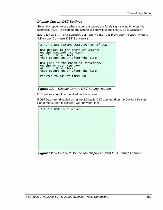
Time of Day Menu
ATC-1000, ATC-2000 & ATC-3000 Advanced Traffic Controllers 153
Display Current DST Settings Select this option to see what the current values are for daylight saving time on this controller. If DST is disabled, the screen will show just one line, “DST is Disabled’.
(MAIN MENU > 2.PROGRAMMING > 4.TIME OF DAY > 6.DAYLIGHT SAVING SETUP > 3.DISPLAY CURRENT DST SETTINGS)
2.4.7.1 DST Params (Occurrences of DOW) DST Begins in the month of <March> on the <Second> <Sunday> at 02:00:00 o'clock. that occurs on or after the <1st> DST Ends in the month of <November> on the <First> <Sunday> at 01:00:00 o'clock. that occurs on or after the <1st> Minutes to Adjust time: 60
Figure 122 – Display Current DST Settings screen DST values cannot be modified on this screen.
If DST has been disabled using the 2.Disable DST command on the Daylight Saving Setup Menu, then this screen will show that fact:
2.4.7.1 DST is Disabled
Figure 123 – Disabled DST on the Display Current DST Settings screen
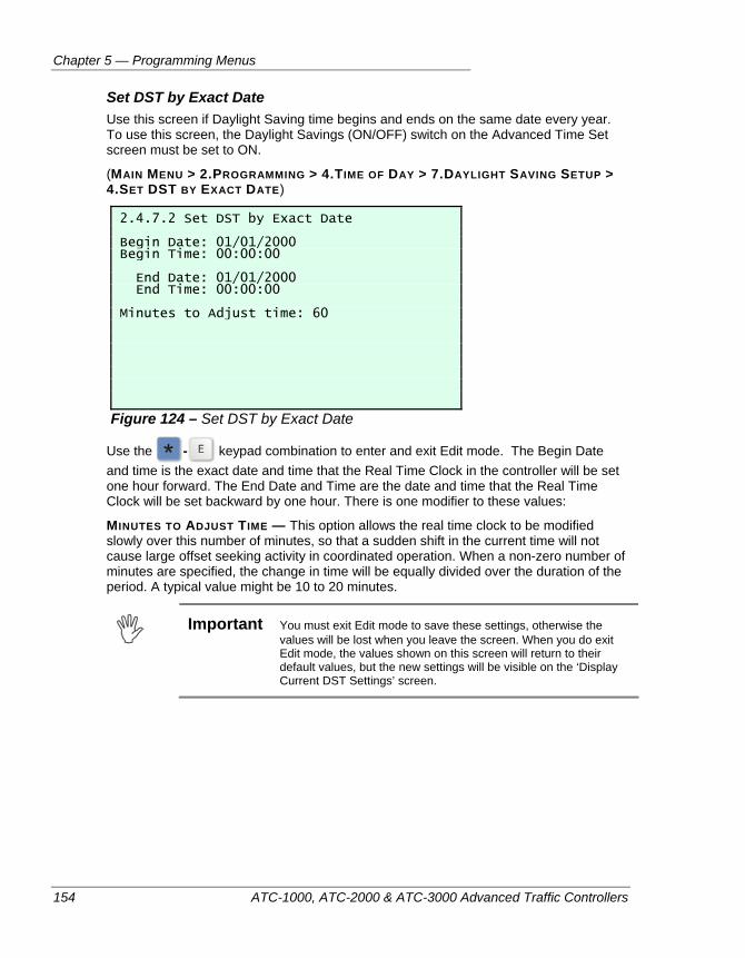
Chapter 5 — Programming Menus
154 ATC-1000, ATC-2000 & ATC-3000 Advanced Traffic Controllers
Set DST by Exact Date Use this screen if Daylight Saving time begins and ends on the same date every year. To use this screen, the Daylight Savings (ON/OFF) switch on the Advanced Time Set screen must be set to ON.
(MAIN MENU > 2.PROGRAMMING > 4.TIME OF DAY > 7.DAYLIGHT SAVING SETUP > 4.SET DST BY EXACT DATE)
2.4.7.2 Set DST by Exact Date Begin Date: 01/01/2000 Begin Time: 00:00:00 End Date: 01/01/2000 End Time: 00:00:00 Minutes to Adjust time: 60
Figure 124 – Set DST by Exact Date
Use the - keypad combination to enter and exit Edit mode. The Begin Date and time is the exact date and time that the Real Time Clock in the controller will be set one hour forward. The End Date and Time are the date and time that the Real Time Clock will be set backward by one hour. There is one modifier to these values:
MINUTES TO ADJUST TIME — This option allows the real time clock to be modified slowly over this number of minutes, so that a sudden shift in the current time will not cause large offset seeking activity in coordinated operation. When a non-zero number of minutes are specified, the change in time will be equally divided over the duration of the period. A typical value might be 10 to 20 minutes.
Important You must exit Edit mode to save these settings, otherwise the
values will be lost when you leave the screen. When you do exit Edit mode, the values shown on this screen will return to their default values, but the new settings will be visible on the ‘Display Current DST Settings’ screen.
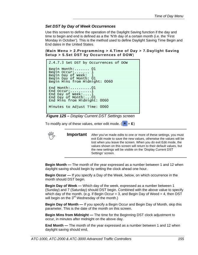
Time of Day Menu
ATC-1000, ATC-2000 & ATC-3000 Advanced Traffic Controllers 155
Set DST by Day of Week Occurrences Use this screen to define the operation of the Daylight Saving function if the day and time to begin and end is defined as a the ‘N’th day of a certain month (i.e. the ‘First Monday in October’). This is the method used to define Daylight Saving Time Begin and End dates in the United States.
(Main Menu > 2.Programming > 4.Time of Day > 7.Dayl ight Saving Setup > 5.Set DST by Occurrences of DOW )
2.4.7.3 Set DST by Occurrences of DOW Begin Month:....... 01 Begin Occur:....... 1 Begin Day of Week: 1 Begin Day of Month: 01 Begin Mins from Midnight: 0060 End Month:..........01 End Occur:..........1 End Day of Week:....1 End Day of Month:...01 End Mins from Midnight: 0060 Minutes to Adjust Time: 0060
Figure 125 – Display Current DST Settings screen
To modify any of these values, enter edit mode. ( + E)
Important After you’ve made edits to one or more of these settings, you must
exit Edit mode to save the new values, otherwise the values will be lost when you leave the screen. When you do exit Edit mode, the values shown on this screen will return to their default values, but the new settings will be visible on the ‘Display Current DST Settings’ screen.
Begin Month — The month of the year expressed as a number between 1 and 12 when daylight saving should begin by setting the clock ahead one hour.
Begin Occur — If you specify a Day of the Week, below, on which occurrence in the month should DST begin.
Begin Day of Week — Which day of the week, expressed as a number between 1 (Sunday) and 7 (Saturday) should DST begin. Combined with the above value to specify which day of the month. (e.g. if Begin Occur = 3, and Begin Day of Weed = 4, then DST will begin on the 3rd Wednesday of the month.)
Begin Day of Month — If you specify a Begin Occur and Begin Day of Month, skip this parameter. This is the date of the month on this screen.
Begin Mins from Midnight — The time for the Beginning DST clock adjustment to occur, in minutes after midnight on the above day.
End Month — The month of the year expressed as a number between 1 and 12 when daylight saving should end,
Chapter 5 — Programming Menus
156 ATC-1000, ATC-2000 & ATC-3000 Advanced Traffic Controllers
End Occur — If you specify a Day of the Week, below, on which occurrence in the month should DST end.
End Day of Week — Which day of the week, expressed as a number between 1 (Sunday) and 7 (Saturday) should DST end.
End Day of Month — If you specify a End Occur and End Day of Month, skip this parameter. This is the date of the month on this screen.
End Mins from Midnight — The time for the Ending DST clock adjustment to occur, in minutes after midnight on the above day.
Minutes to Adjust Time – This option allows the real time clock to be modified slowly over this number of minutes, so that a sudden shift in the current time will not cause large offset seeking activity in coordinated operation. When a non-zero number of minutes are specified, the change in time will be equally divided over the duration of the period. A typical value might be 10 to 20 minutes.
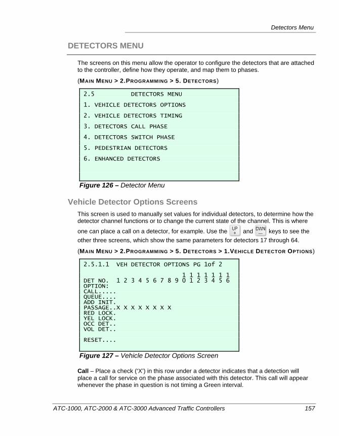
Detectors Menu
ATC-1000, ATC-2000 & ATC-3000 Advanced Traffic Controllers 157
DETECTORS MENU
The screens on this menu allow the operator to configure the detectors that are attached to the controller, define how they operate, and map them to phases.
(MAIN MENU > 2.PROGRAMMING > 5. DETECTORS)
2.5 DETECTORS MENU 1. VEHICLE DETECTORS OPTIONS 2. VEHICLE DETECTORS TIMING 3. DETECTORS CALL PHASE 4. DETECTORS SWITCH PHASE 5. PEDESTRIAN DETECTORS 6. ENHANCED DETECTORS
Figure 126 – Detector Menu
Vehicle Detector Options Screens This screen is used to manually set values for individual detectors, to determine how the detector channel functions or to change the current state of the channel. This is where
one can place a call on a detector, for example. Use the and keys to see the other three screens, which show the same parameters for detectors 17 through 64.
(MAIN MENU > 2.PROGRAMMING > 5. DETECTORS > 1.VEHICLE DETECTOR OPTIONS)
2.5.1.1 VEH DETECTOR OPTIONS PG 1of 2 1 1 1 1 1 1 1 DET NO. 1 2 3 4 5 6 7 8 9 0 1 2 3 4 5 6 OPTION: CALL..... QUEUE.... ADD INIT. PASSAGE..X X X X X X X X RED LOCK. YEL LOCK. OCC DET.. VOL DET.. RESET....
Figure 127 – Vehicle Detector Options Screen
Call – Place a check (‘X’) in this row under a detector indicates that a detection will place a call for service on the phase associated with this detector. This call will appear whenever the phase in question is not timing a Green interval.
Chapter 5 — Programming Menus
158 ATC-1000, ATC-2000 & ATC-3000 Advanced Traffic Controllers
Queue – Place a check (‘X’) on this row under a detector to indicate that this detector is used for gap detection. A queue detector will extend the Green interval of the assigned phase until a gap occurs, or until the Green phase times longer than the optional queue limit.
Add Init – An ‘X’ placed in this row beneath a detector indicates that that detector will be used to generate detection inputs for the Added Init function of Initial Green extension. The method used is to count the vehicle detections from all detectors associated with the phase, take the detector with the highest count total, and multiply that count total by the Added Init time step. This extra time is then compared to the minimum and maximum time in effect and utilized, but only if it is greater than the minimum and less than the maximum.
Passage – When this row is checked (‘X’) the controller will maintain a reset of the associated phase’s Passage Timer for the duration of the detector actuation, while the phase is green.
Red Lock – When this row is checked (‘X’) the controller will lock a call to the assigned phase if an actuation occurs while the phase is not showing green or yellow.
Yel Lock – When this row is checked (‘X’) the controller will lock a call to the assigned phase if an actuation occurs while the phase is not showing green.
Occ Det – When this row is checked (‘X’) then this detector is marked as an ‘occupancy detector’. An occupancy detector collects data for the associated phase’s occupancy calculations.
Vol Det – When this row is checked (‘X’) then this detector is marked as a ‘volume detector’. A volume detector collects data for the associated phase’s volume calculations.
Reset – This sends a reset command to the detector, forcing it to return to FALSE (0) after the reset command. A reset command is an interactive control that is not stored in the controller database. The reset command is sent as soon as you press Yes on the keypad.
Note A reset command may reset more than one detector, if other detectors are attached to a common physical reset channel, as is often the case.
Note For all of these per-detector functions, it’s important to remember that the detectors are not associated with individual phases on this screen. That mapping is defined on the “Detector Call Phases Screen”, which is described on page 160.
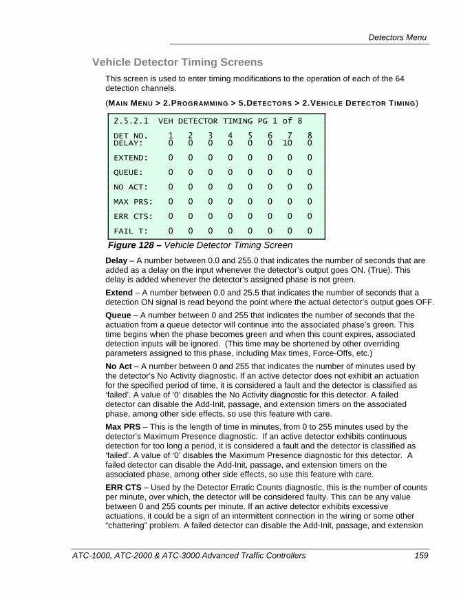
Detectors Menu
ATC-1000, ATC-2000 & ATC-3000 Advanced Traffic Controllers 159
Vehicle Detector Timing Screens This screen is used to enter timing modifications to the operation of each of the 64 detection channels.
(MAIN MENU > 2.PROGRAMMING > 5.DETECTORS > 2.VEHICLE DETECTOR TIMING)
2.5.2.1 VEH DETECTOR TIMING PG 1 of 8 DET NO. 1 2 3 4 5 6 7 8 DELAY: 0 0 0 0 0 0 10 0 EXTEND: 0 0 0 0 0 0 0 0 QUEUE: 0 0 0 0 0 0 0 0 NO ACT: 0 0 0 0 0 0 0 0 MAX PRS: 0 0 0 0 0 0 0 0 ERR CTS: 0 0 0 0 0 0 0 0 FAIL T: 0 0 0 0 0 0 0 0
Figure 128 – Vehicle Detector Timing Screen Delay – A number between 0.0 and 255.0 that indicates the number of seconds that are added as a delay on the input whenever the detector’s output goes ON. (True). This delay is added whenever the detector’s assigned phase is not green. Extend – A number between 0.0 and 25.5 that indicates the number of seconds that a detection ON signal is read beyond the point where the actual detector’s output goes OFF. Queue – A number between 0 and 255 that indicates the number of seconds that the actuation from a queue detector will continue into the associated phase’s green. This time begins when the phase becomes green and when this count expires, associated detection inputs will be ignored. (This time may be shortened by other overriding parameters assigned to this phase, including Max times, Force-Offs, etc.) No Act – A number between 0 and 255 that indicates the number of minutes used by the detector’s No Activity diagnostic. If an active detector does not exhibit an actuation for the specified period of time, it is considered a fault and the detector is classified as ‘failed’. A value of ‘0’ disables the No Activity diagnostic for this detector. A failed detector can disable the Add-Init, passage, and extension timers on the associated phase, among other side effects, so use this feature with care. Max PRS – This is the length of time in minutes, from 0 to 255 minutes used by the detector’s Maximum Presence diagnostic. If an active detector exhibits continuous detection for too long a period, it is considered a fault and the detector is classified as ‘failed’. A value of ‘0’ disables the Maximum Presence diagnostic for this detector. A failed detector can disable the Add-Init, passage, and extension timers on the associated phase, among other side effects, so use this feature with care. ERR CTS – Used by the Detector Erratic Counts diagnostic, this is the number of counts per minute, over which, the detector will be considered faulty. This can be any value between 0 and 255 counts per minute. If an active detector exhibits excessive actuations, it could be a sign of an intermittent connection in the wiring or some other “chattering” problem. A failed detector can disable the Add-Init, passage, and extension
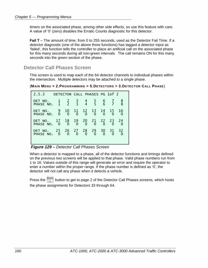
Chapter 5 — Programming Menus
160 ATC-1000, ATC-2000 & ATC-3000 Advanced Traffic Controllers
timers on the associated phase, among other side effects, so use this feature with care. A value of ‘0’ (zero) disables the Erratic Counts diagnostic for this detector.
Fail T – The amount of time, from 0 to 255 seconds, used as the Detector Fail Time. If a detector diagnostic (one of the above three functions) has tagged a detector input as ‘failed’, this function tells the controller to place an artificial call on the associated phase for this many seconds during all non-green intervals. The call remains ON for this many seconds into the green section of the phase.
Detector Call Phases Screen This screen is used to map each of the 64 detector channels to individual phases within the intersection. Multiple detectors may be attached to a single phase.
(MAIN MENU > 2.PROGRAMMING > 5.DETECTORS > 3.DETECTOR CALL PHASE)
2.5.3 DETECTOR CALL PHASES PG 1of 2 DET NO. 1 2 3 4 5 6 7 8 PHASE NO. 1 2 3 4 5 6 7 8 DET NO. 9 10 11 12 13 14 15 16 PHASE NO. 0 0 0 0 0 0 0 0 DET NO. 17 18 19 20 21 22 23 24 PHASE NO. 0 0 0 0 0 0 0 0 DET NO. 25 26 27 28 29 30 31 32 PHASE NO. 0 0 0 0 0 0 0 0
Figure 129 – Detector Call Phases Screen When a detector is mapped to a phase, all of the detector functions and timings defined on the previous two screens will be applied to that phase. Valid phase numbers run from 1 to 16. Values outside of this range will generate an error and require the operator to enter a number within the proper range. If the phase number is defined as ‘0’, the detector will not call any phase when it detects a vehicle.
Press the button to get to page 2 of the Detector Call Phases screens, which hosts the phase assignments for Detectors 33 through 64.
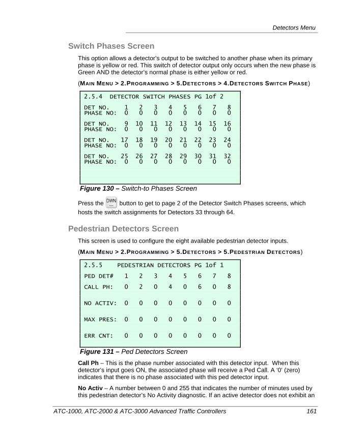
Detectors Menu
ATC-1000, ATC-2000 & ATC-3000 Advanced Traffic Controllers 161
Switch Phases Screen This option allows a detector’s output to be switched to another phase when its primary phase is yellow or red. This switch of detector output only occurs when the new phase is Green AND the detector’s normal phase is either yellow or red.
(MAIN MENU > 2.PROGRAMMING > 5.DETECTORS > 4.DETECTORS SWITCH PHASE)
2.5.4 DETECTOR SWITCH PHASES PG 1of 2 DET NO. 1 2 3 4 5 6 7 8 PHASE NO: 0 0 0 0 0 0 0 0 DET NO. 9 10 11 12 13 14 15 16 PHASE NO: 0 0 0 0 0 0 0 0 DET NO. 17 18 19 20 21 22 23 24 PHASE NO: 0 0 0 0 0 0 0 0 DET NO. 25 26 27 28 29 30 31 32 PHASE NO: 0 0 0 0 0 0 0 0
Figure 130 – Switch-to Phases Screen
Press the button to get to page 2 of the Detector Switch Phases screens, which hosts the switch assignments for Detectors 33 through 64.
Pedestrian Detectors Screen This screen is used to configure the eight available pedestrian detector inputs.
(MAIN MENU > 2.PROGRAMMING > 5.DETECTORS > 5.PEDESTRIAN DETECTORS)
2.5.5 PEDESTRIAN DETECTORS PG 1of 1 PED DET# 1 2 3 4 5 6 7 8 CALL PH: 0 2 0 4 0 6 0 8 NO ACTIV: 0 0 0 0 0 0 0 0 MAX PRES: 0 0 0 0 0 0 0 0 ERR CNT: 0 0 0 0 0 0 0 0
Figure 131 – Ped Detectors Screen Call Ph – This is the phase number associated with this detector input. When this detector’s input goes ON, the associated phase will receive a Ped Call. A ‘0’ (zero) indicates that there is no phase associated with this ped detector input.
No Activ – A number between 0 and 255 that indicates the number of minutes used by this pedestrian detector’s No Activity diagnostic. If an active detector does not exhibit an
Chapter 5 — Programming Menus
162 ATC-1000, ATC-2000 & ATC-3000 Advanced Traffic Controllers
actuation for the specified period of time, it is considered a fault and the detector is classified as ‘failed’. A value of ‘0’ disables the No Activity diagnostic for this detector.
Max Pres – This is the length of time in minutes, from 0 to 255 minutes used by the ped detector’s Maximum Presence diagnostic. If an active pedestrian detector exhibits continuous detection for too long a period, it is considered a fault and the detector is classified as ‘failed’. A value of ‘0’ disables the Maximum Presence diagnostic for this ped detector.
ERR CNT – Used by the Ped Detector Erratic Counts diagnostic, this is the number of counts per minute, if exceeded, which will cause the ped detector to be considered faulty. This can be any value between 0 and 255 counts per minute. If an active detector exhibits excessive actuations, it could be a sign of an intermittent connection in the wiring or some other “chattering” problem. A value of ‘0’ (zero) disables the Erratic Counts diagnostic for this pedestrian detector input.
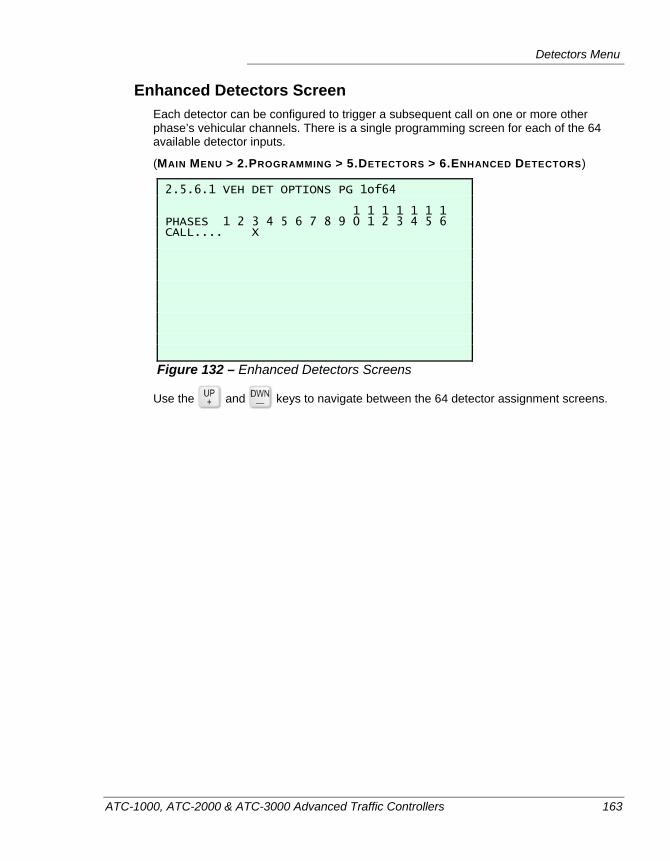
Detectors Menu
ATC-1000, ATC-2000 & ATC-3000 Advanced Traffic Controllers 163
Enhanced Detectors Screen Each detector can be configured to trigger a subsequent call on one or more other phase’s vehicular channels. There is a single programming screen for each of the 64 available detector inputs.
(MAIN MENU > 2.PROGRAMMING > 5.DETECTORS > 6.ENHANCED DETECTORS)
2.5.6.1 VEH DET OPTIONS PG 1of64 1 1 1 1 1 1 1 PHASES 1 2 3 4 5 6 7 8 9 0 1 2 3 4 5 6 CALL.... X
Figure 132 – Enhanced Detectors Screens
Use the and keys to navigate between the 64 detector assignment screens.
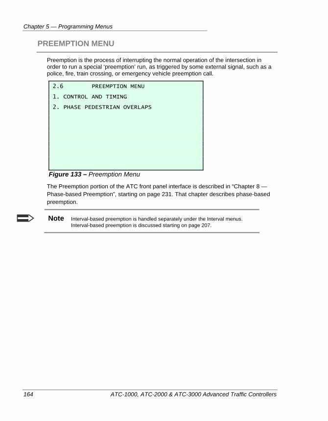
Chapter 5 — Programming Menus
164 ATC-1000, ATC-2000 & ATC-3000 Advanced Traffic Controllers
PREEMPTION MENU
Preemption is the process of interrupting the normal operation of the intersection in order to run a special ‘preemption’ run, as triggered by some external signal, such as a police, fire, train crossing, or emergency vehicle preemption call.
2.6 PREEMPTION MENU 1. CONTROL AND TIMING 2. PHASE PEDESTRIAN OVERLAPS
Figure 133 – Preemption Menu
The Preemption portion of the ATC front panel interface is described in “Chapter 8 — Phase-based Preemption”, starting on page 231. That chapter describes phase-based preemption.
Note Interval-based preemption is handled separately under the Interval menus. Interval-based preemption is discussed starting on page 207.
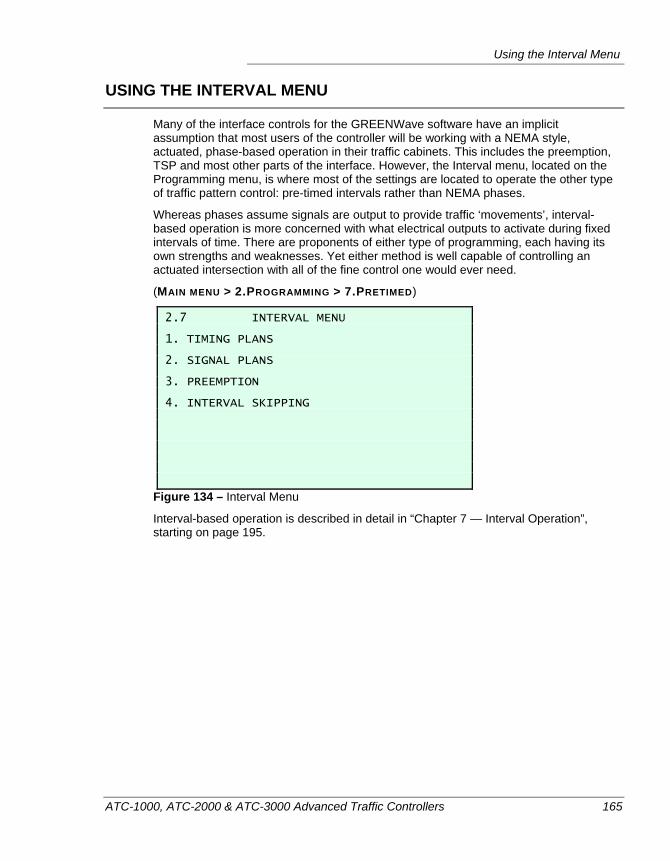
Using the Interval Menu
ATC-1000, ATC-2000 & ATC-3000 Advanced Traffic Controllers 165
USING THE INTERVAL MENU
Many of the interface controls for the GREENWave software have an implicit assumption that most users of the controller will be working with a NEMA style, actuated, phase-based operation in their traffic cabinets. This includes the preemption, TSP and most other parts of the interface. However, the Interval menu, located on the Programming menu, is where most of the settings are located to operate the other type of traffic pattern control: pre-timed intervals rather than NEMA phases.
Whereas phases assume signals are output to provide traffic ‘movements’, interval-based operation is more concerned with what electrical outputs to activate during fixed intervals of time. There are proponents of either type of programming, each having its own strengths and weaknesses. Yet either method is well capable of controlling an actuated intersection with all of the fine control one would ever need.
(MAIN MENU > 2.PROGRAMMING > 7.PRETIMED)
2.7 INTERVAL MENU 1. TIMING PLANS 2. SIGNAL PLANS 3. PREEMPTION 4. INTERVAL SKIPPING
Figure 134 – Interval Menu
Interval-based operation is described in detail in “Chapter 7 — Interval Operation”, starting on page 195.
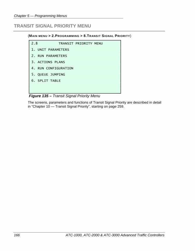
Chapter 5 — Programming Menus
166 ATC-1000, ATC-2000 & ATC-3000 Advanced Traffic Controllers
TRANSIT SIGNAL PRIORITY MENU
(MAIN MENU > 2.PROGRAMMING > 8.TRANSIT SIGNAL PRIORITY)
2.8 TRANSIT PRIORITY MENU 1. UNIT PARAMETERS 2. RUN PARAMETERS 3. ACTIONS PLANS 4. RUN CONFIGURATION 5. QUEUE JUMPING 6. SPLIT TABLE
Figure 135 – Transit Signal Priority Menu The screens, parameters and functions of Transit Signal Priority are described in detail in “Chapter 10 — Transit Signal Priority”, starting on page 259.
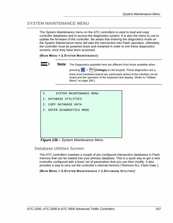
System Maintenance Menu
ATC-1000, ATC-2000 & ATC-3000 Advanced Traffic Controllers 167
SYSTEM MAINTENANCE MENU
The System Maintenance menu on the ATC controllers is used to load and copy controller databases and to access the diagnostics system. It is also the menu to use to update the firmware of the controller. Be aware that entering the diagnostics mode on the System Maintenance menu will take the intersection into Flash operation. Ultimately, the controller must be powered down and restarted in order to exit these diagnostics screens, once they have been accessed.
(MAIN MENU > 3.SYSTEM MAINTENANCE)
Note The Diagnostics available here are different from those available when
pressing + (Voltage) on the keypad. Those diagnostics are a lower level hardware-based set, particularly aimed at the interface circuit board and the operation of the keyboard and display. (Refer to “Utilities Menu” on page 280.)
3 SYSTEM MAINTENANCE MENU 1. DATABASE UTILITIES 2. COPY DATABASE DATA 3. ENTER DIAGNOSTICS MODE
Figure 136 – System Maintenance Menu
Database Utilities Screen The ATC controllers maintain a couple of pre-configured intersection databases in Flash memory that can be loaded into your primary database. This is a quick way to get a new controller configured with a basic set of parameters that you can then modify. It also provides a way to zero out the controller’s internal memory (‘Remove ALL Flash Data.’)
(MAIN MENU > 3.SYSTEM MAINTENANCE > 1.DATABASE UTILITIES)
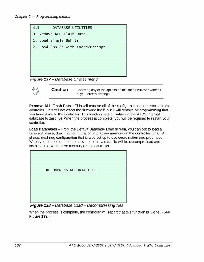
Chapter 5 — Programming Menus
168 ATC-1000, ATC-2000 & ATC-3000 Advanced Traffic Controllers
3.1 DATABASE UTILITIES 0. Remove ALL Flash Data. 1. Load simple 8ph 2r. 2. Load 8ph 2r with Coord/Preempt
Figure 137 – Database Utilities menu
Caution Choosing any of the options on this menu will over-write all
of your current settings.
Remove ALL Flash Data – This will remove all of the configuration values stored in the controller. This will not affect the firmware itself, but it will remove all programming that you have done to the controller. This function sets all values in the ATC’s internal database to zero (0). When the process is complete, you will be required to restart your controller.
Load Databases – From the Default Database Load screen, you can opt to load a simple 8 phase, dual ring configuration into active memory on the controller, or an 8 phase, dual ring configuration that is also set up to use coordination and preemption. When you choose one of the above options, a data file will be decompressed and installed into your active memory on the controller.
DECOMPRESSING DATA FILE
Figure 138 – Database Load – Decompressing files When the process is complete, the controller will report that this function is ‘Done’. (See Figure 139.)
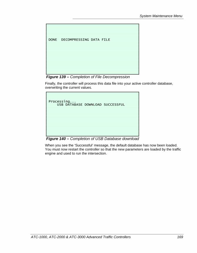
System Maintenance Menu
ATC-1000, ATC-2000 & ATC-3000 Advanced Traffic Controllers 169
DONE DECOMPRESSING DATA FILE
Figure 139 – Completion of File Decompression Finally, the controller will process this data file into your active controller database, overwriting the current values.
Processing... USB DATABASE DOWNLOAD SUCCESSFUL
Figure 140 – Completion of USB Database download When you see the ‘Successful’ message, the default database has now been loaded. You must now restart the controller so that the new parameters are loaded by the traffic engine and used to run the intersection.
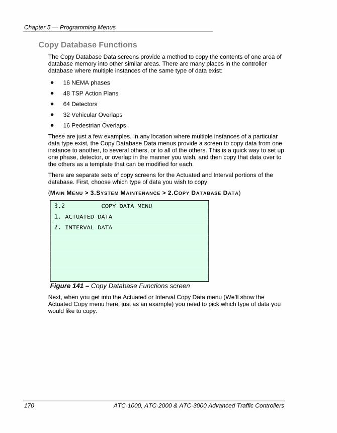
Chapter 5 — Programming Menus
170 ATC-1000, ATC-2000 & ATC-3000 Advanced Traffic Controllers
Copy Database Functions The Copy Database Data screens provide a method to copy the contents of one area of database memory into other similar areas. There are many places in the controller database where multiple instances of the same type of data exist:
16 NEMA phases
48 TSP Action Plans
64 Detectors
32 Vehicular Overlaps
16 Pedestrian Overlaps
These are just a few examples. In any location where multiple instances of a particular data type exist, the Copy Database Data menus provide a screen to copy data from one instance to another, to several others, or to all of the others. This is a quick way to set up one phase, detector, or overlap in the manner you wish, and then copy that data over to the others as a template that can be modified for each.
There are separate sets of copy screens for the Actuated and Interval portions of the database. First, choose which type of data you wish to copy.
(MAIN MENU > 3.SYSTEM MAINTENANCE > 2.COPY DATABASE DATA)
3.2 COPY DATA MENU 1. ACTUATED DATA 2. INTERVAL DATA
Figure 141 – Copy Database Functions screen Next, when you get into the Actuated or Interval Copy Data menu (We’ll show the Actuated Copy menu here, just as an example) you need to pick which type of data you would like to copy.
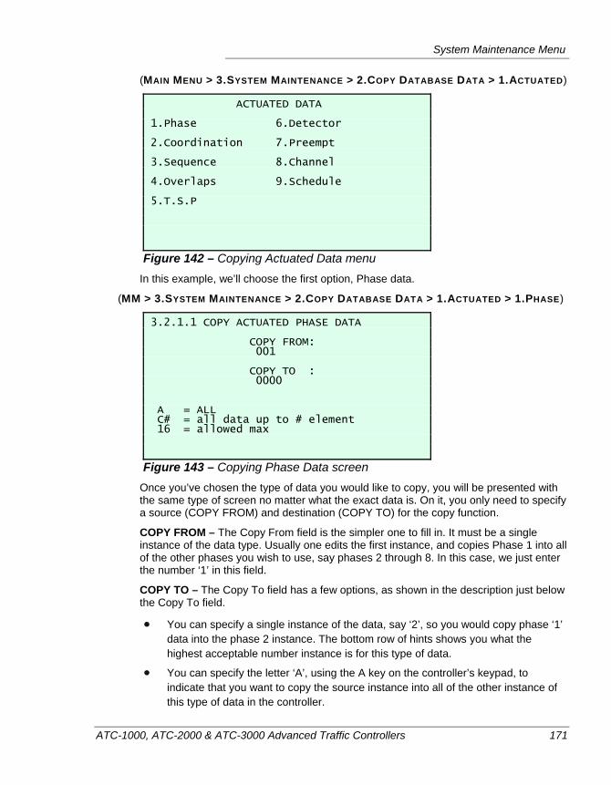
System Maintenance Menu
ATC-1000, ATC-2000 & ATC-3000 Advanced Traffic Controllers 171
(MAIN MENU > 3.SYSTEM MAINTENANCE > 2.COPY DATABASE DATA > 1.ACTUATED)
ACTUATED DATA 1.Phase 6.Detector 2.Coordination 7.Preempt 3.Sequence 8.Channel 4.Overlaps 9.Schedule 5.T.S.P
Figure 142 – Copying Actuated Data menu In this example, we’ll choose the first option, Phase data.
(MM > 3.SYSTEM MAINTENANCE > 2.COPY DATABASE DATA > 1.ACTUATED > 1.PHASE)
3.2.1.1 COPY ACTUATED PHASE DATA COPY FROM: 001 COPY TO : 0000 A = ALL C# = all data up to # element 16 = allowed max
Figure 143 – Copying Phase Data screen Once you’ve chosen the type of data you would like to copy, you will be presented with the same type of screen no matter what the exact data is. On it, you only need to specify a source (COPY FROM) and destination (COPY TO) for the copy function.
COPY FROM – The Copy From field is the simpler one to fill in. It must be a single instance of the data type. Usually one edits the first instance, and copies Phase 1 into all of the other phases you wish to use, say phases 2 through 8. In this case, we just enter the number ‘1’ in this field.
COPY TO – The Copy To field has a few options, as shown in the description just below the Copy To field.
You can specify a single instance of the data, say ‘2’, so you would copy phase ‘1’ data into the phase 2 instance. The bottom row of hints shows you what the highest acceptable number instance is for this type of data.
You can specify the letter ‘A’, using the A key on the controller’s keypad, to indicate that you want to copy the source instance into all of the other instance of this type of data in the controller.
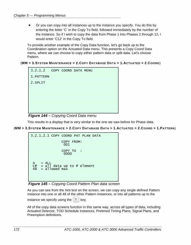
Chapter 5 — Programming Menus
172 ATC-1000, ATC-2000 & ATC-3000 Advanced Traffic Controllers
Or you can copy into all instances up to the instance you specify. You do this by entering the letter ‘C’ in the Copy To field, followed immediately by the number of the instance. So if I wish to copy the data from Phase 1 into Phases 2 through 12, I would enter ‘C12’ in the Copy To field.
To provide another example of the Copy Data function, let’s go back up to the Coordination option on the Actuated Data menu. This presents a Copy Coord Data menu, where we can choose to copy either pattern data or split data. Let’s choose Pattern.
(MM > 3.SYSTEM MAINTENANCE > 2.COPY DATABASE DATA > 1.ACTUATED > 2.COORD)
3.2.1.2 COPY COORD DATA MENU 1.PATTERN 2.SPLIT
Figure 144 – Copying Coord Data menu This results in a display that is very similar to the one we saw before for Phase data.
(MM > 3.SYSTEM MAINTENANCE > 2.COPY DATABASE DATA > 1.ACTUATED > 2.COORD > 1.PATTERN)
3.2.1.2.1 COPY COORD PAT PLAN DATA COPY FROM: 001 COPY TO : 0000 A = ALL C# = all data up to # element 48 = allowed max
Figure 145 – Copying Coord Pattern Plan data screen As you can see from the hint text on the screen, we can copy any single defined Pattern instance into one or all 48 of the other Pattern instances, or into all patterns up to the instance we specify using the key.
All of the copy data screens function in this same way, across all types of data, including Actuated Detector, TOD Schedule instances, Pretimed Timing Plans, Signal Plans, and Preemption definitions.
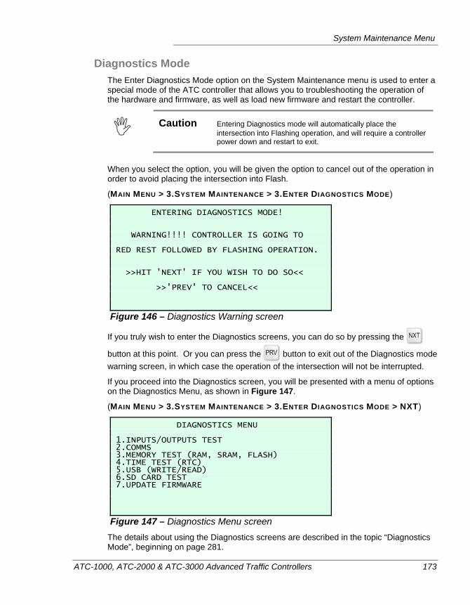
System Maintenance Menu
ATC-1000, ATC-2000 & ATC-3000 Advanced Traffic Controllers 173
Diagnostics Mode The Enter Diagnostics Mode option on the System Maintenance menu is used to enter a special mode of the ATC controller that allows you to troubleshooting the operation of the hardware and firmware, as well as load new firmware and restart the controller.
Caution Entering Diagnostics mode will automatically place the
intersection into Flashing operation, and will require a controller power down and restart to exit.
When you select the option, you will be given the option to cancel out of the operation in order to avoid placing the intersection into Flash.
(MAIN MENU > 3.SYSTEM MAINTENANCE > 3.ENTER DIAGNOSTICS MODE)
ENTERING DIAGNOSTICS MODE! WARNING!!!! CONTROLLER IS GOING TO RED REST FOLLOWED BY FLASHING OPERATION. >>HIT 'NEXT' IF YOU WISH TO DO SO<< >>'PREV' TO CANCEL<<
Figure 146 – Diagnostics Warning screen
If you truly wish to enter the Diagnostics screens, you can do so by pressing the
button at this point. Or you can press the button to exit out of the Diagnostics mode warning screen, in which case the operation of the intersection will not be interrupted.
If you proceed into the Diagnostics screen, you will be presented with a menu of options on the Diagnostics Menu, as shown in Figure 147.
(MAIN MENU > 3.SYSTEM MAINTENANCE > 3.ENTER DIAGNOSTICS MODE > NXT)
DIAGNOSTICS MENU 1.INPUTS/OUTPUTS TEST 2.COMMS 3.MEMORY TEST (RAM, SRAM, FLASH) 4.TIME TEST (RTC) 5.USB (WRITE/READ) 6.SD CARD TEST 7.UPDATE FIRMWARE
Figure 147 – Diagnostics Menu screen The details about using the Diagnostics screens are described in the topic “Diagnostics Mode”, beginning on page 281.
Chapter 5 — Programming Menus
174 ATC-1000, ATC-2000 & ATC-3000 Advanced Traffic Controllers
LOGS MENU
The commands and log viewing screens are described in the “Data Logging” topic, starting on page 292.
ATC-1000, ATC-2000 & ATC-3000 Advanced Traffic Controllers 175
Chapter 6 — Coordinated Operation
This chapter describes how to set up coordinated operation on an ATC controller. The following topics are discussed in detail in this chapter:
• General overview of coordination, on page 176.
• Signal timing in a coordinated environment, on page 177.
• Synchronization methods, on page 179.
• Coordination of an actuated controller, on page 180.
• Example of coordination programming, on page 183.
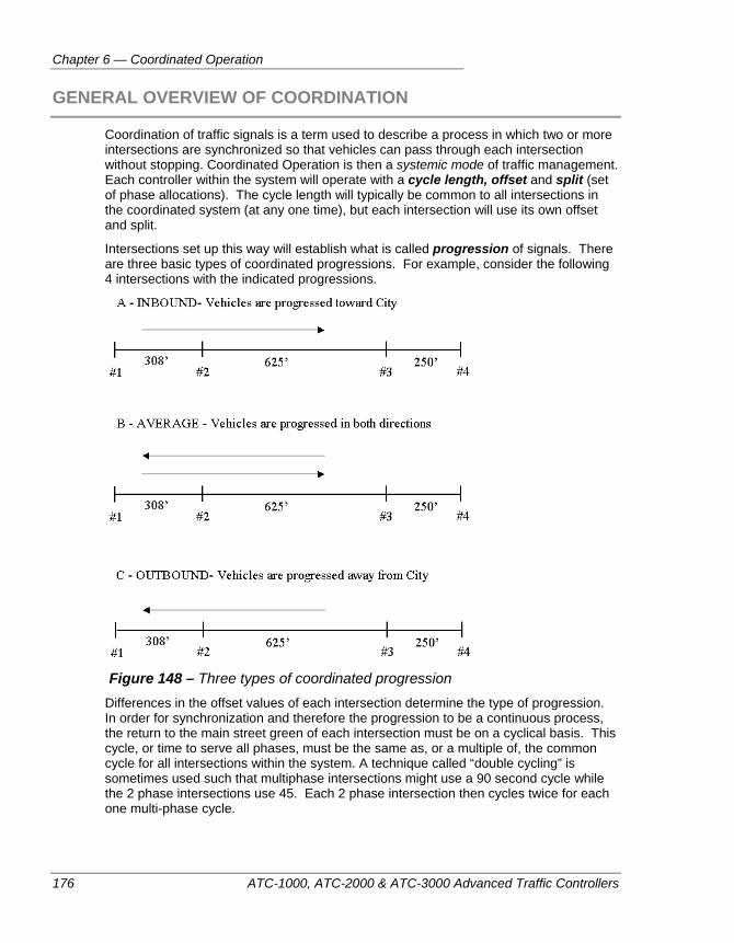
Chapter 6 — Coordinated Operation
176 ATC-1000, ATC-2000 & ATC-3000 Advanced Traffic Controllers
GENERAL OVERVIEW OF COORDINATION
Coordination of traffic signals is a term used to describe a process in which two or more intersections are synchronized so that vehicles can pass through each intersection without stopping. Coordinated Operation is then a systemic mode of traffic management. Each controller within the system will operate with a cycle length, offset and split (set of phase allocations). The cycle length will typically be common to all intersections in the coordinated system (at any one time), but each intersection will use its own offset and split.
Intersections set up this way will establish what is called progression of signals. There are three basic types of coordinated progressions. For example, consider the following 4 intersections with the indicated progressions.
Figure 148 – Three types of coordinated progression
Differences in the offset values of each intersection determine the type of progression. In order for synchronization and therefore the progression to be a continuous process, the return to the main street green of each intersection must be on a cyclical basis. This cycle, or time to serve all phases, must be the same as, or a multiple of, the common cycle for all intersections within the system. A technique called “double cycling” is sometimes used such that multiphase intersections might use a 90 second cycle while the 2 phase intersections use 45. Each 2 phase intersection then cycles twice for each one multi-phase cycle.
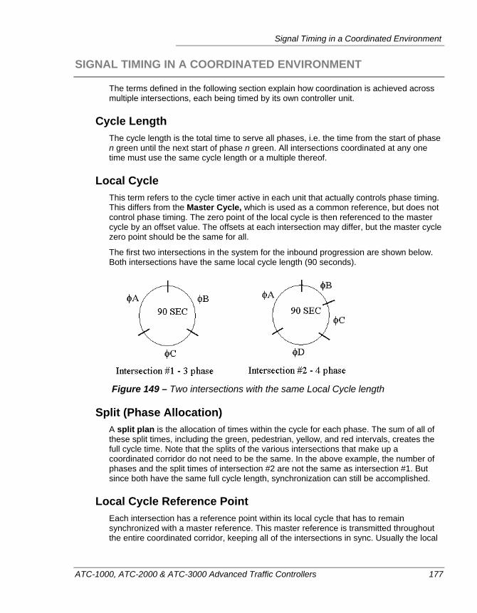
Signal Timing in a Coordinated Environment
ATC-1000, ATC-2000 & ATC-3000 Advanced Traffic Controllers 177
SIGNAL TIMING IN A COORDINATED ENVIRONMENT
The terms defined in the following section explain how coordination is achieved across multiple intersections, each being timed by its own controller unit.
Cycle Length The cycle length is the total time to serve all phases, i.e. the time from the start of phase n green until the next start of phase n green. All intersections coordinated at any one time must use the same cycle length or a multiple thereof.
Local Cycle This term refers to the cycle timer active in each unit that actually controls phase timing. This differs from the Master Cycle, which is used as a common reference, but does not control phase timing. The zero point of the local cycle is then referenced to the master cycle by an offset value. The offsets at each intersection may differ, but the master cycle zero point should be the same for all.
The first two intersections in the system for the inbound progression are shown below. Both intersections have the same local cycle length (90 seconds).
Figure 149 – Two intersections with the same Local Cycle length
Split (Phase Allocation) A split plan is the allocation of times within the cycle for each phase. The sum of all of these split times, including the green, pedestrian, yellow, and red intervals, creates the full cycle time. Note that the splits of the various intersections that make up a coordinated corridor do not need to be the same. In the above example, the number of phases and the split times of intersection #2 are not the same as intersection #1. But since both have the same full cycle length, synchronization can still be accomplished.
Local Cycle Reference Point Each intersection has a reference point within its local cycle that has to remain synchronized with a master reference. This master reference is transmitted throughout the entire coordinated corridor, keeping all of the intersections in sync. Usually the local
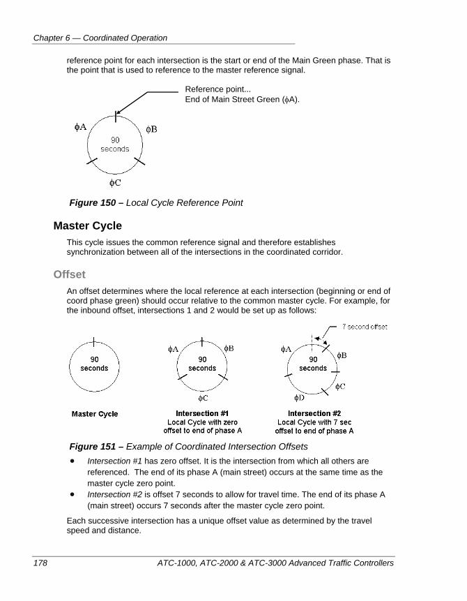
Chapter 6 — Coordinated Operation
178 ATC-1000, ATC-2000 & ATC-3000 Advanced Traffic Controllers
reference point for each intersection is the start or end of the Main Green phase. That is the point that is used to reference to the master reference signal.
Figure 150 – Local Cycle Reference Point
Master Cycle This cycle issues the common reference signal and therefore establishes synchronization between all of the intersections in the coordinated corridor.
Offset An offset determines where the local reference at each intersection (beginning or end of coord phase green) should occur relative to the common master cycle. For example, for the inbound offset, intersections 1 and 2 would be set up as follows:
Figure 151 – Example of Coordinated Intersection Offsets
Intersection #1 has zero offset. It is the intersection from which all others are referenced. The end of its phase A (main street) occurs at the same time as the master cycle zero point.
Intersection #2 is offset 7 seconds to allow for travel time. The end of its phase A (main street) occurs 7 seconds after the master cycle zero point.
Each successive intersection has a unique offset value as determined by the travel speed and distance.
Reference point... End of Main Street Green (φA).
Synchronization Methods
ATC-1000, ATC-2000 & ATC-3000 Advanced Traffic Controllers 179
SYNCHRONIZATION METHODS
Historical Sources of Sync Pulses The traditional master cycle used for referencing in years past was a 3-second pulse of zero volts from a 115VAC signal via a hardwire interconnect. All intersections would reference and synchronize themselves to these "Sync Pulses” as generated by a master dial unit. Over the years, however, other methods of providing referencing sync pulses have been incorporated and have for the most part replaced the 115VAC hardwire interconnect.
One of the more popular methods today is Time Based Coordination in which there is no interconnect at all, but each controller internally generates its own master cycle based on its internal clock and the time of day. This is a very popular technique because no interconnect system has to be installed.
Another method is through a communications link such as 2 twisted pair wire, radio, or fiber optics. Under such communications links, far more sophisticated information can be passed to and from each intersection, not just simple sync pulse commands.
Offset Seeking The local cycle timer is not always at the proper offset relative to the master cycle. It can be “out of step” upon system start-up, if cycle or offset changes are made, or after preemption. Offset seeking describes the process of getting the local cycle back into step with the master cycle. The local cycle can either time a percentage faster, slower, or stop until the proper reference is achieved.
Each method avoids abruptness, so as not to disrupt traffic. Offset seeking can sometimes take five cycles to get back in step. This seeking process is necessary to ensure a smooth transition from one pattern to another without skipping, over-timing or short-timing phases.
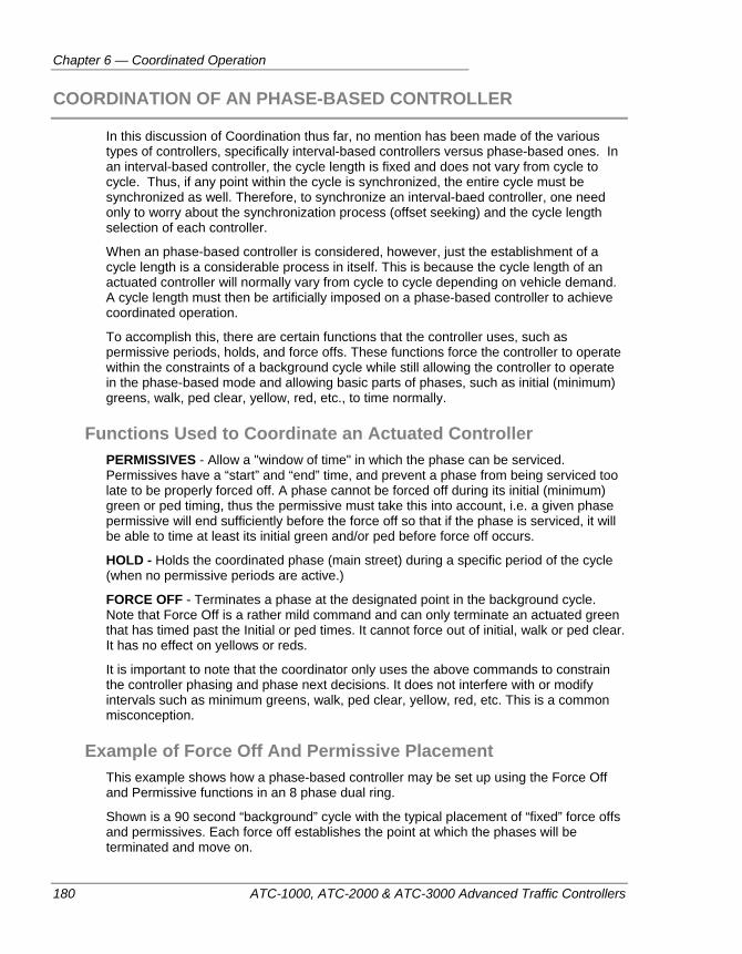
Chapter 6 — Coordinated Operation
180 ATC-1000, ATC-2000 & ATC-3000 Advanced Traffic Controllers
COORDINATION OF AN PHASE-BASED CONTROLLER
In this discussion of Coordination thus far, no mention has been made of the various types of controllers, specifically interval-based controllers versus phase-based ones. In an interval-based controller, the cycle length is fixed and does not vary from cycle to cycle. Thus, if any point within the cycle is synchronized, the entire cycle must be synchronized as well. Therefore, to synchronize an interval-baed controller, one need only to worry about the synchronization process (offset seeking) and the cycle length selection of each controller.
When an phase-based controller is considered, however, just the establishment of a cycle length is a considerable process in itself. This is because the cycle length of an actuated controller will normally vary from cycle to cycle depending on vehicle demand. A cycle length must then be artificially imposed on a phase-based controller to achieve coordinated operation.
To accomplish this, there are certain functions that the controller uses, such as permissive periods, holds, and force offs. These functions force the controller to operate within the constraints of a background cycle while still allowing the controller to operate in the phase-based mode and allowing basic parts of phases, such as initial (minimum) greens, walk, ped clear, yellow, red, etc., to time normally.
Functions Used to Coordinate an Actuated Controller PERMISSIVES - Allow a "window of time" in which the phase can be serviced. Permissives have a “start” and “end” time, and prevent a phase from being serviced too late to be properly forced off. A phase cannot be forced off during its initial (minimum) green or ped timing, thus the permissive must take this into account, i.e. a given phase permissive will end sufficiently before the force off so that if the phase is serviced, it will be able to time at least its initial green and/or ped before force off occurs.
HOLD - Holds the coordinated phase (main street) during a specific period of the cycle (when no permissive periods are active.)
FORCE OFF - Terminates a phase at the designated point in the background cycle. Note that Force Off is a rather mild command and can only terminate an actuated green that has timed past the Initial or ped times. It cannot force out of initial, walk or ped clear. It has no effect on yellows or reds.
It is important to note that the coordinator only uses the above commands to constrain the controller phasing and phase next decisions. It does not interfere with or modify intervals such as minimum greens, walk, ped clear, yellow, red, etc. This is a common misconception.
Example of Force Off And Permissive Placement This example shows how a phase-based controller may be set up using the Force Off and Permissive functions in an 8 phase dual ring.
Shown is a 90 second “background” cycle with the typical placement of “fixed” force offs and permissives. Each force off establishes the point at which the phases will be terminated and move on.

Coordination of an Phase-Based Controller
ATC-1000, ATC-2000 & ATC-3000 Advanced Traffic Controllers 181
Phases can “gap-out” before they “force off”. If a phase does gap out, the next phase can get more time. Notice that each permissive ends somewhat before the force off for the indicated phase pair. Under full demand on all phases, permissives generally don’t do much. However, under light demand, particularly if the coordinated phase is likely to “rest” or if other phases are likely to be skipped (no demand), permissives make sure that phases are only allowed service at such a point that they can be forced off at their designated time.
Figure 152 – Typical placements of fixed force offs and permissives
Coordination of actuated controllers can be tricky business. Two seemingly contradictory concepts are employed at once. On the one hand, because the controller is actuated, the benefits associated with an actuated controller are desired, i.e. a controller that is responsive to traffic, skips phases with no demand, varies the green appropriately for phases with demand, and finally, one that rests in the main street in absence of any demand. On the other hand, to accomplish coordination, one must constrain the timing so that the controller operates within the confines of the background cycle.
Coordination of actuated signals is often a complex matter, and requires a great deal of effort on the part of the responsible agency to provide the analysis (traffic studies, etc.) required for proper programming and subsequent operation.
Coordination of actuated signals can often be controversial as well. This is primarily due to the nature of their operation. In the case of pre-timed controllers, signal progression tends be well behaved and each signal “nicely” displays its green in just the proper order. Actuated signals, however, do not always seem to behave so nicely. For example, if at a given intersection, all the side street phases do not use all their green time (they "gap-out" before they "force off"), then there will be an "early return" to the main street. The "platoon" of vehicles at that intersection will then be released and may arrive at the next intersection too early, before the green appears. These vehicles will have to stop, which, of course, defeats the purpose of coordination.
There are, however, a couple of things to consider relative to this issue. Firstly, despite the lack of appearance of coordination under such circumstances, the system may actually be more efficient. Even though the pre-timed system may be well coordinated, it often does so by arbitrarily holding the main street red as the side streets are provided with a fixed duration green time, whether needed or not. Conversely, the actuated machine returns to the main street as soon as it can. Since some main street vehicles may turn off before they reach the next intersection, an early return is certainly beneficial to them. For those that proceed through the next intersection, although they may be hampered by arriving too early, they may also have the luck that the next intersection
Start Permissive φ3, 7, 4, 8, 1, & 5
Chapter 6 — Coordinated Operation
182 ATC-1000, ATC-2000 & ATC-3000 Advanced Traffic Controllers
returns to main street early as well, and can proceed unimpeded. Finally, many times an early-return platoon is not part of the "greenband" and does not affect the intended progression. This type of operation does provide maximum efficiency, although it can occasionally appear to be sporadic and unpredictable.
This leads to the second point: proper coordination using actuated controllers requires that the responsible agency provides the proper cycle and split settings for the level and distribution of traffic at any given time of day. If the cycle length and split times are appropriate for the conditions at all times of the day, non-beneficial early returns to the main street can be minimized.
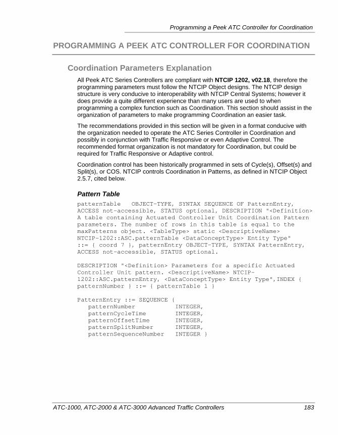
Programming a Peek ATC Controller for Coordination
ATC-1000, ATC-2000 & ATC-3000 Advanced Traffic Controllers 183
PROGRAMMING A PEEK ATC CONTROLLER FOR COORDINATION
Coordination Parameters Explanation All Peek ATC Series Controllers are compliant with NTCIP 1202, v02.18, therefore the programming parameters must follow the NTCIP Object designs. The NTCIP design structure is very conducive to interoperability with NTCIP Central Systems; however it does provide a quite different experience than many users are used to when programming a complex function such as Coordination. This section should assist in the organization of parameters to make programming Coordination an easier task.
The recommendations provided in this section will be given in a format conducive with the organization needed to operate the ATC Series Controller in Coordination and possibly in conjunction with Traffic Responsive or even Adaptive Control. The recommended format organization is not mandatory for Coordination, but could be required for Traffic Responsive or Adaptive control.
Coordination control has been historically programmed in sets of Cycle(s), Offset(s) and Split(s), or COS. NTCIP controls Coordination in Patterns, as defined in NTCIP Object 2.5.7, cited below.
Pattern Table patternTable OBJECT-TYPE, SYNTAX SEQUENCE OF PatternEntry, ACCESS not-accessible, STATUS optional, DESCRIPTION "<Definition> A table containing Actuated Controller Unit Coordination Pattern parameters. The number of rows in this table is equal to the maxPatterns object. <TableType> static <DescriptiveName> NTCIP-1202::ASC.patternTable <DataConceptType> Entity Type" ::= { coord 7 }, patternEntry OBJECT-TYPE, SYNTAX PatternEntry, ACCESS not-accessible, STATUS optional. DESCRIPTION "<Definition> Parameters for a specific Actuated Controller Unit pattern. <DescriptiveName> NTCIP-1202::ASC.patternEntry, <DataConceptType> Entity Type",INDEX { patternNumber } ::= { patternTable 1 } PatternEntry ::= SEQUENCE { patternNumber INTEGER, patternCycleTime INTEGER, patternOffsetTime INTEGER, patternSplitNumber INTEGER, patternSequenceNumber INTEGER }
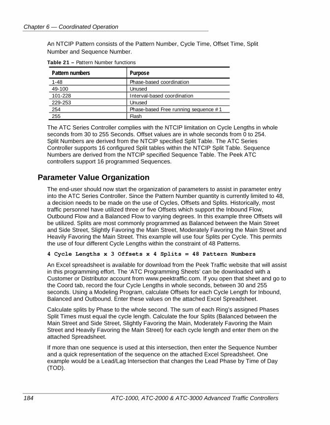
Chapter 6 — Coordinated Operation
184 ATC-1000, ATC-2000 & ATC-3000 Advanced Traffic Controllers
An NTCIP Pattern consists of the Pattern Number, Cycle Time, Offset Time, Split Number and Sequence Number.
Table 21 – Pattern Number functions
Pattern numbers Purpose 1-48 Phase-based coordination 49-100 Unused 101-228 Interval-based coordination 229-253 Unused 254 Phase-based Free running sequence #1 255 Flash
The ATC Series Controller complies with the NTCIP limitation on Cycle Lengths in whole seconds from 30 to 255 Seconds. Offset values are in whole seconds from 0 to 254. Split Numbers are derived from the NTCIP specified Split Table. The ATC Series Controller supports 16 configured Split tables within the NTCIP Split Table. Sequence Numbers are derived from the NTCIP specified Sequence Table. The Peek ATC controllers support 16 programmed Sequences.
Parameter Value Organization The end-user should now start the organization of parameters to assist in parameter entry into the ATC Series Controller. Since the Pattern Number quantity is currently limited to 48, a decision needs to be made on the use of Cycles, Offsets and Splits. Historically, most traffic personnel have utilized three or five Offsets which support the Inbound Flow, Outbound Flow and a Balanced Flow to varying degrees. In this example three Offsets will be utilized. Splits are most commonly programmed as Balanced between the Main Street and Side Street, Slightly Favoring the Main Street, Moderately Favoring the Main Street and Heavily Favoring the Main Street. This example will use four Splits per Cycle. This permits the use of four different Cycle Lengths within the constraint of 48 Patterns.
4 Cycle Lengths x 3 Offsets x 4 Splits = 48 Pattern Numbers
An Excel spreadsheet is available for download from the Peek Traffic website that will assist in this programming effort. The ‘ATC Programming Sheets’ can be downloaded with a Customer or Distributor account from www.peektraffic.com. If you open that sheet and go to the Coord tab, record the four Cycle Lengths in whole seconds, between 30 and 255 seconds. Using a Modeling Program, calculate Offsets for each Cycle Length for Inbound, Balanced and Outbound. Enter these values on the attached Excel Spreadsheet.
Calculate splits by Phase to the whole second. The sum of each Ring’s assigned Phases Split Times must equal the cycle length. Calculate the four Splits (Balanced between the Main Street and Side Street, Slightly Favoring the Main, Moderately Favoring the Main Street and Heavily Favoring the Main Street) for each cycle length and enter them on the attached Spreadsheet.
If more than one sequence is used at this intersection, then enter the Sequence Number and a quick representation of the sequence on the attached Excel Spreadsheet. One example would be a Lead/Lag Intersection that changes the Lead Phase by Time of Day (TOD).
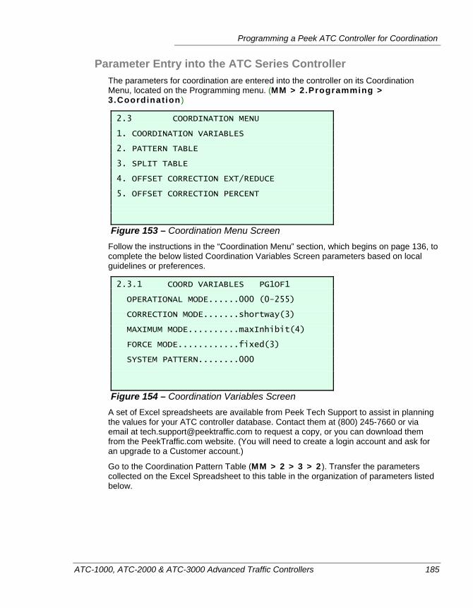
Programming a Peek ATC Controller for Coordination
ATC-1000, ATC-2000 & ATC-3000 Advanced Traffic Controllers 185
Parameter Entry into the ATC Series Controller The parameters for coordination are entered into the controller on its Coordination Menu, located on the Programming menu. (MM > 2.Programming > 3.Coordinat ion )
2.3 COORDINATION MENU 1. COORDINATION VARIABLES 2. PATTERN TABLE 3. SPLIT TABLE 4. OFFSET CORRECTION EXT/REDUCE 5. OFFSET CORRECTION PERCENT
Figure 153 – Coordination Menu Screen Follow the instructions in the “Coordination Menu” section, which begins on page 136, to complete the below listed Coordination Variables Screen parameters based on local guidelines or preferences.
2.3.1 COORD VARIABLES PG1OF1 OPERATIONAL MODE......000 (0-255) CORRECTION MODE.......shortway(3) MAXIMUM MODE..........maxInhibit(4) FORCE MODE............fixed(3) SYSTEM PATTERN........000
Figure 154 – Coordination Variables Screen A set of Excel spreadsheets are available from Peek Tech Support to assist in planning the values for your ATC controller database. Contact them at (800) 245-7660 or via email at [email protected] to request a copy, or you can download them from the PeekTraffic.com website. (You will need to create a login account and ask for an upgrade to a Customer account.)
Go to the Coordination Pattern Table (MM > 2 > 3 > 2 ). Transfer the parameters collected on the Excel Spreadsheet to this table in the organization of parameters listed below.
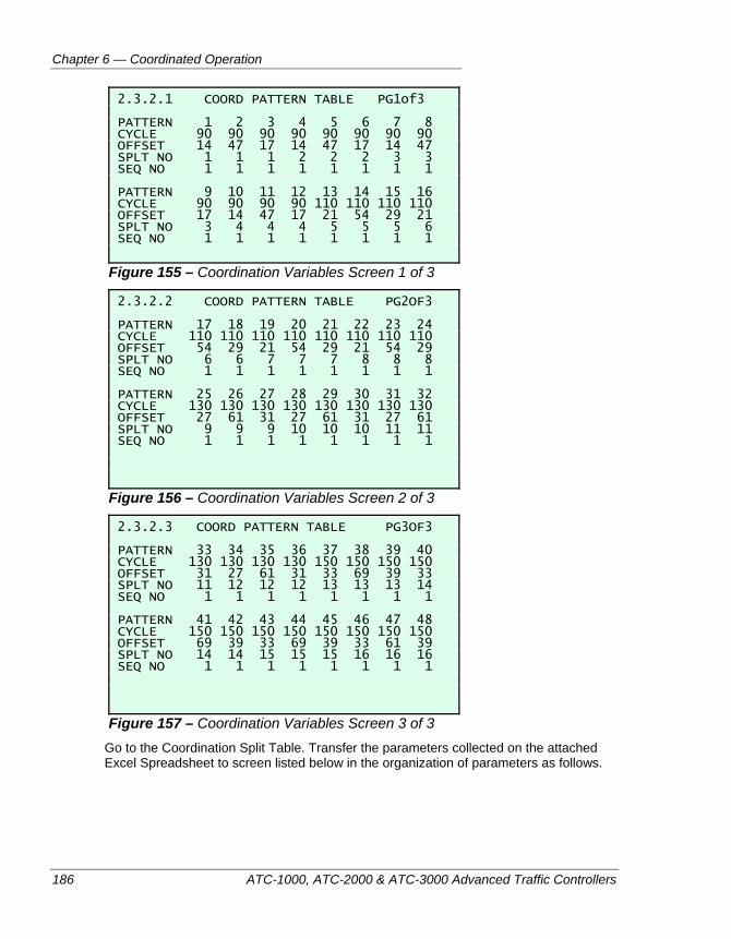
Chapter 6 — Coordinated Operation
186 ATC-1000, ATC-2000 & ATC-3000 Advanced Traffic Controllers
2.3.2.1 COORD PATTERN TABLE PG1of3 PATTERN 1 2 3 4 5 6 7 8 CYCLE 90 90 90 90 90 90 90 90 OFFSET 14 47 17 14 47 17 14 47 SPLT NO 1 1 1 2 2 2 3 3 SEQ NO 1 1 1 1 1 1 1 1 PATTERN 9 10 11 12 13 14 15 16 CYCLE 90 90 90 90 110 110 110 110 OFFSET 17 14 47 17 21 54 29 21 SPLT NO 3 4 4 4 5 5 5 6 SEQ NO 1 1 1 1 1 1 1 1
Figure 155 – Coordination Variables Screen 1 of 3
2.3.2.2 COORD PATTERN TABLE PG2OF3 PATTERN 17 18 19 20 21 22 23 24 CYCLE 110 110 110 110 110 110 110 110 OFFSET 54 29 21 54 29 21 54 29 SPLT NO 6 6 7 7 7 8 8 8 SEQ NO 1 1 1 1 1 1 1 1 PATTERN 25 26 27 28 29 30 31 32 CYCLE 130 130 130 130 130 130 130 130 OFFSET 27 61 31 27 61 31 27 61 SPLT NO 9 9 9 10 10 10 11 11 SEQ NO 1 1 1 1 1 1 1 1
Figure 156 – Coordination Variables Screen 2 of 3
2.3.2.3 COORD PATTERN TABLE PG3OF3 PATTERN 33 34 35 36 37 38 39 40 CYCLE 130 130 130 130 150 150 150 150 OFFSET 31 27 61 31 33 69 39 33 SPLT NO 11 12 12 12 13 13 13 14 SEQ NO 1 1 1 1 1 1 1 1 PATTERN 41 42 43 44 45 46 47 48 CYCLE 150 150 150 150 150 150 150 150 OFFSET 69 39 33 69 39 33 61 39 SPLT NO 14 14 15 15 15 16 16 16 SEQ NO 1 1 1 1 1 1 1 1
Figure 157 – Coordination Variables Screen 3 of 3 Go to the Coordination Split Table. Transfer the parameters collected on the attached Excel Spreadsheet to screen listed below in the organization of parameters as follows.
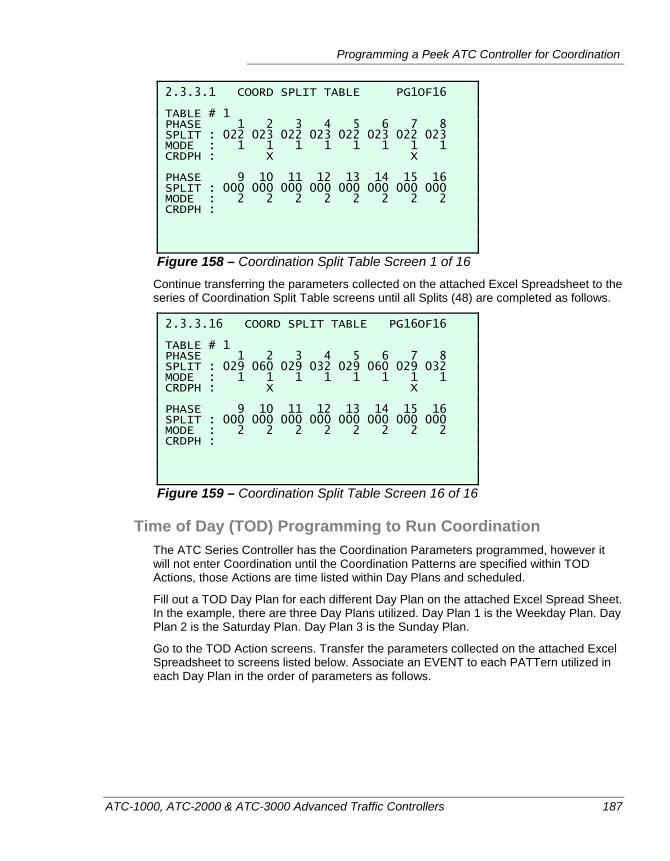
Programming a Peek ATC Controller for Coordination
ATC-1000, ATC-2000 & ATC-3000 Advanced Traffic Controllers 187
2.3.3.1 COORD SPLIT TABLE PG1OF16 TABLE # 1 PHASE 1 2 3 4 5 6 7 8 SPLIT : 022 023 022 023 022 023 022 023 MODE : 1 1 1 1 1 1 1 1 CRDPH : X X PHASE 9 10 11 12 13 14 15 16 SPLIT : 000 000 000 000 000 000 000 000 MODE : 2 2 2 2 2 2 2 2 CRDPH :
Figure 158 – Coordination Split Table Screen 1 of 16 Continue transferring the parameters collected on the attached Excel Spreadsheet to the series of Coordination Split Table screens until all Splits (48) are completed as follows.
2.3.3.16 COORD SPLIT TABLE PG16OF16 TABLE # 1 PHASE 1 2 3 4 5 6 7 8 SPLIT : 029 060 029 032 029 060 029 032 MODE : 1 1 1 1 1 1 1 1 CRDPH : X X PHASE 9 10 11 12 13 14 15 16 SPLIT : 000 000 000 000 000 000 000 000 MODE : 2 2 2 2 2 2 2 2 CRDPH :
Figure 159 – Coordination Split Table Screen 16 of 16
Time of Day (TOD) Programming to Run Coordination The ATC Series Controller has the Coordination Parameters programmed, however it will not enter Coordination until the Coordination Patterns are specified within TOD Actions, those Actions are time listed within Day Plans and scheduled.
Fill out a TOD Day Plan for each different Day Plan on the attached Excel Spread Sheet. In the example, there are three Day Plans utilized. Day Plan 1 is the Weekday Plan. Day Plan 2 is the Saturday Plan. Day Plan 3 is the Sunday Plan.
Go to the TOD Action screens. Transfer the parameters collected on the attached Excel Spreadsheet to screens listed below. Associate an EVENT to each PATTern utilized in each Day Plan in the order of parameters as follows.
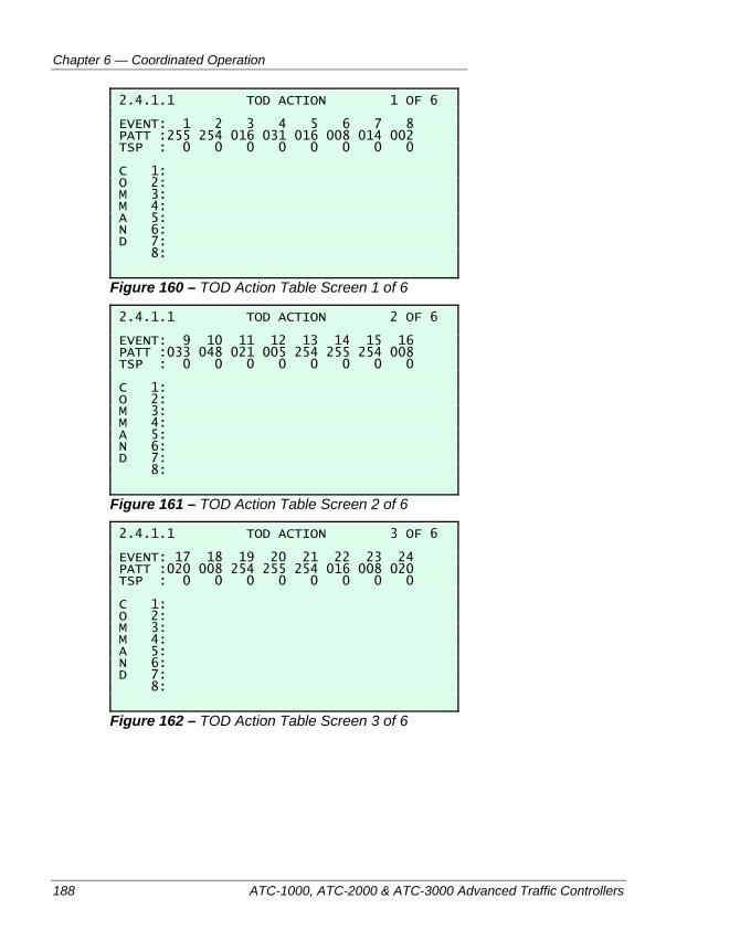
Chapter 6 — Coordinated Operation
188 ATC-1000, ATC-2000 & ATC-3000 Advanced Traffic Controllers
2.4.1.1 TOD ACTION 1 OF 6 EVENT: 1 2 3 4 5 6 7 8 PATT :255 254 016 031 016 008 014 002 TSP : 0 0 0 0 0 0 0 0 C 1: O 2: M 3: M 4: A 5: N 6: D 7: 8:
Figure 160 – TOD Action Table Screen 1 of 6
2.4.1.1 TOD ACTION 2 OF 6 EVENT: 9 10 11 12 13 14 15 16 PATT :033 048 021 005 254 255 254 008 TSP : 0 0 0 0 0 0 0 0 C 1: O 2: M 3: M 4: A 5: N 6: D 7: 8:
Figure 161 – TOD Action Table Screen 2 of 6
2.4.1.1 TOD ACTION 3 OF 6 EVENT: 17 18 19 20 21 22 23 24 PATT :020 008 254 255 254 016 008 020 TSP : 0 0 0 0 0 0 0 0 C 1: O 2: M 3: M 4: A 5: N 6: D 7: 8:
Figure 162 – TOD Action Table Screen 3 of 6
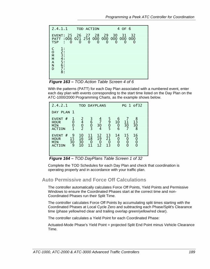
Programming a Peek ATC Controller for Coordination
ATC-1000, ATC-2000 & ATC-3000 Advanced Traffic Controllers 189
2.4.1.1 TOD ACTION 4 OF 6 EVENT: 25 26 27 28 29 30 31 32 PATT :006 021 254 000 000 000 000 000 TSP : 0 0 0 0 0 0 0 0 C 1: O 2: M 3: M 4: A 5: N 6: D 7: 8:
Figure 163 – TOD Action Table Screen 4 of 6 With the patterns (PATT) for each Day Plan associated with a numbered event, enter each day plan with events corresponding to the start time listed on the Day Plan on the ATC-1000/2000 Programming Charts, as the example shows below.
2.4.2.1 TOD DAYPLANS PG 1 of32 DAY PLAN 1 EVENT # 1 2 3 4 5 6 7 8 HOUR 0 4 6 7 9 10 11 13 MIN 0 0 0 30 0 0 30 30 ACTION 1 2 3 4 5 6 7 8 EVENT # 9 10 11 12 13 14 15 16 HOUR 15 16 18 19 21 0 0 0 MIN 30 30 0 0 0 0 0 0 ACTION 9 10 11 12 13 0 0 0
Figure 164 – TOD DayPlans Table Screen 1 of 32 Complete the TOD Schedules for each Day Plan and check that coordination is operating properly and in accordance with your traffic plan.
Auto Permissive and Force Off Calculations The controller automatically calculates Force Off Points, Yield Points and Permissive Windows to ensure the Coordinated Phases start at the correct time and non-Coordinated Phases run their Split Time.
The controller calculates Force Off Points by accumulating split times starting with the Coordinated Phases at Local Cycle Zero and subtracting each Phase/Split's Clearance time (phase yellow/red clear and trailing overlap green/yellow/red clear).
The controller calculates a Yield Point for each Coordinated Phase:
Actuated-Mode Phase's Yield Point = projected Split End Point minus Vehicle Clearance Time.
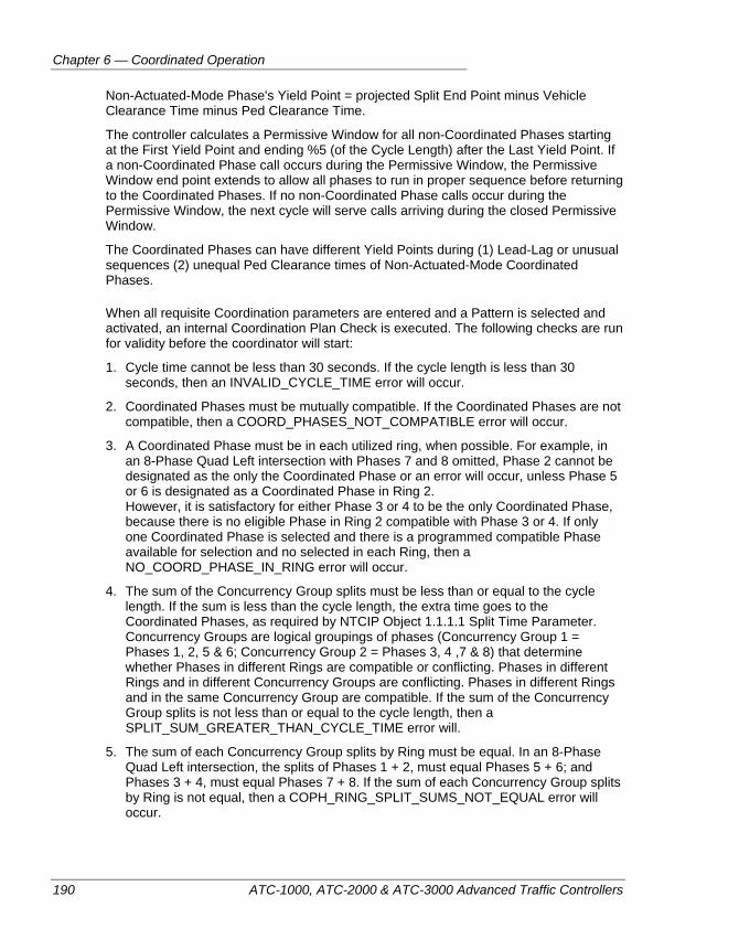
Chapter 6 — Coordinated Operation
190 ATC-1000, ATC-2000 & ATC-3000 Advanced Traffic Controllers
Non-Actuated-Mode Phase's Yield Point = projected Split End Point minus Vehicle Clearance Time minus Ped Clearance Time.
The controller calculates a Permissive Window for all non-Coordinated Phases starting at the First Yield Point and ending %5 (of the Cycle Length) after the Last Yield Point. If a non-Coordinated Phase call occurs during the Permissive Window, the Permissive Window end point extends to allow all phases to run in proper sequence before returning to the Coordinated Phases. If no non-Coordinated Phase calls occur during the Permissive Window, the next cycle will serve calls arriving during the closed Permissive Window.
The Coordinated Phases can have different Yield Points during (1) Lead-Lag or unusual sequences (2) unequal Ped Clearance times of Non-Actuated-Mode Coordinated Phases.
When all requisite Coordination parameters are entered and a Pattern is selected and activated, an internal Coordination Plan Check is executed. The following checks are run for validity before the coordinator will start:
1. Cycle time cannot be less than 30 seconds. If the cycle length is less than 30 seconds, then an INVALID_CYCLE_TIME error will occur.
2. Coordinated Phases must be mutually compatible. If the Coordinated Phases are not compatible, then a COORD_PHASES_NOT_COMPATIBLE error will occur.
3. A Coordinated Phase must be in each utilized ring, when possible. For example, in an 8-Phase Quad Left intersection with Phases 7 and 8 omitted, Phase 2 cannot be designated as the only the Coordinated Phase or an error will occur, unless Phase 5 or 6 is designated as a Coordinated Phase in Ring 2. However, it is satisfactory for either Phase 3 or 4 to be the only Coordinated Phase, because there is no eligible Phase in Ring 2 compatible with Phase 3 or 4. If only one Coordinated Phase is selected and there is a programmed compatible Phase available for selection and no selected in each Ring, then a NO_COORD_PHASE_IN_RING error will occur.
4. The sum of the Concurrency Group splits must be less than or equal to the cycle length. If the sum is less than the cycle length, the extra time goes to the Coordinated Phases, as required by NTCIP Object 1.1.1.1 Split Time Parameter. Concurrency Groups are logical groupings of phases (Concurrency Group 1 = Phases 1, 2, 5 & 6; Concurrency Group 2 = Phases 3, 4 ,7 & 8) that determine whether Phases in different Rings are compatible or conflicting. Phases in different Rings and in different Concurrency Groups are conflicting. Phases in different Rings and in the same Concurrency Group are compatible. If the sum of the Concurrency Group splits is not less than or equal to the cycle length, then a SPLIT_SUM_GREATER_THAN_CYCLE_TIME error will.
5. The sum of each Concurrency Group splits by Ring must be equal. In an 8-Phase Quad Left intersection, the splits of Phases 1 + 2, must equal Phases 5 + 6; and Phases 3 + 4, must equal Phases 7 + 8. If the sum of each Concurrency Group splits by Ring is not equal, then a COPH_RING_SPLIT_SUMS_NOT_EQUAL error will occur.
Programming a Peek ATC Controller for Coordination
ATC-1000, ATC-2000 & ATC-3000 Advanced Traffic Controllers 191
Definition A Barrier Phase is a phase that must turn off with other phase(s) when advancing to its next phase(s), assuming every phase has a call. In a standard 8-phase, 2-ring sequence, phases 2,4,6, and 8 are Barrier Phases. Phase 2 is a Barrier Phase because Phase 6 must turn off when Phase 2 advances to its next phases (3 and 7). The same reasoning makes Phases 4, 6, and 8 Barrier Phases.
6. Phase Minimum Green Check. An INIT_GREATER_THAN_PHASE_SPLIT error will occur if: a) Each non-Barrier phase’s Initial/Min Green + Yellow + Red Clear is greater than the Split Time, OR b) Each Barrier phase’s Initial/Min Green + (largest Yellow + Red Clear sum of the Concurrency Group’s phases) is greater than the Split Time.
7. Phase Minimum Pedestrian Check. A PED_TIME_GREATER_THAN _PHASE_SPLIT error will occur if: a) Each CNA non-Barrier phase’s Walk+Ped Clearance + Yellow + Red Clear is greater than the Split Time, OR b) Each CNA Barrier phase’s Walk+Ped Clearance + (largest Yellow + Red Clear sum of the Barrier Phase and its compatible/concurrency phases) is greater than the Split Time.
8. A Trail or Trailing Overlap is the NTCIP Object feature commonly known as a Double Clearing Overlap. A Trail (or Trailing) Overlap yellow + Trail Overlap red + Parent Phase initial/min green must be less than or equal to the Parent Phase’s split time. For example, Phase 1 is a Parent Phase for Overlap A, which is a Trail Overlap. Phase 1’s split = 20 seconds. Phase 1’s initial/min green = 10 seconds. A TRAILING_OVERLAP_SPLIT_ERROR error will occur, if Overlap A’s programmed trail yellow + trail red is greater than 10 seconds.
9. The Offset time for each Cycle cannot be greater than the cycle time. If cycle length is 100 seconds and Offset for 110 seconds is entered, it will use an offset of 10 seconds, and an OFFSET_TIME_GREATER_THAN_CYCLE_TIME error will occur.
The dynamic display reads Bad Plan-> X, where X is one of the nine errors listed above. If more than one error is found, only one error will be displayed at one time. All errors must be cleared for the ATC to enter Coordination.
The Coord Pattern Status, Local Free Status, Coord Cycle Status (Seconds) and Coord Synch Status (Seconds) on the Mode/Status/Control Tab of the Coordination Window submenu will be explained after the Pattern Table and Split Table Tabs are discussed below, so operating Coordination will display status seen during normal Coordination operation.
Notes About Programming a Coordinated Pattern Table NTCIP Object 2.5.7, states that the object of Pattern Table is a sequence table containing Actuated Controller Unit Coordination Pattern Parameters. The number of rows in this table is equal to the maxPatterns object. Parameters for a specific Actuated
Chapter 6 — Coordinated Operation
192 ATC-1000, ATC-2000 & ATC-3000 Advanced Traffic Controllers
Controller Unit pattern are: patternNumber, patternCycleTime, patternOffsetTime, patternSplitNumber and patternSequenceNumber.
Keeping in mind that an ATC controller may be used in a threshold-based Traffic Responsive mode (such as the Traffic Responsive module available in IQ Central), the entry of Plans should be in an organized manner conducive to Traffic Responsive Operations. For such purposes, the programming demonstrated below will consist of four progressive Pattern Cycle Time(s) or cycle lengths arranged from shortest to longest; three Pattern Offset Time(s) arranged as Inbound (I), Balanced (B) and Outbound (O); and four splits for Balanced (B), Slightly (S), Moderately (M) and Heavily (H) favoring the Main Street Coordinated Phases.
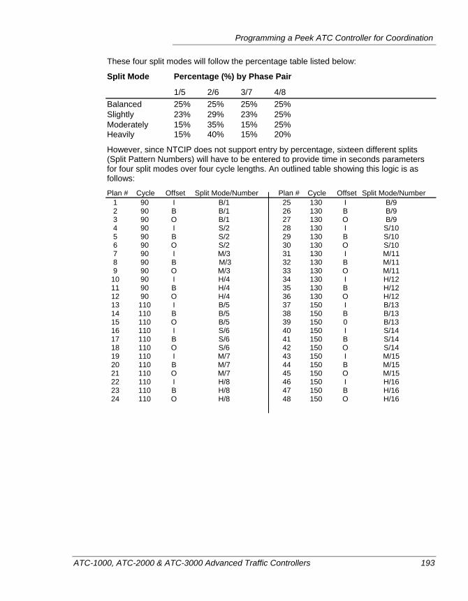
Programming a Peek ATC Controller for Coordination
ATC-1000, ATC-2000 & ATC-3000 Advanced Traffic Controllers 193
These four split modes will follow the percentage table listed below:
Split Mode Percentage (%) by Phase Pair
1/5 2/6 3/7 4/8 Balanced 25% 25% 25% 25% Slightly 23% 29% 23% 25% Moderately 15% 35% 15% 25% Heavily 15% 40% 15% 20%
However, since NTCIP does not support entry by percentage, sixteen different splits (Split Pattern Numbers) will have to be entered to provide time in seconds parameters for four split modes over four cycle lengths. An outlined table showing this logic is as follows:
Plan # Cycle Offset Split Mode/Number Plan # Cycle Offset Split Mode/Number 1 90 I B/1 25 130 I B/9 2 90 B B/1 26 130 B B/9 3 90 O B/1 27 130 O B/9 4 90 I S/2 28 130 I S/10 5 90 B S/2 29 130 B S/10 6 90 O S/2 30 130 O S/10 7 90 I M/3 31 130 I M/11 8 90 B M/3 32 130 B M/11 9 90 O M/3 33 130 O M/11 10 90 I H/4 34 130 I H/12 11 90 B H/4 35 130 B H/12 12 90 O H/4 36 130 O H/12 13 110 I B/5 37 150 I B/13 14 110 B B/5 38 150 B B/13 15 110 O B/5 39 150 0 B/13 16 110 I S/6 40 150 I S/14 17 110 B S/6 41 150 B S/14 18 110 O S/6 42 150 O S/14 19 110 I M/7 43 150 I M/15 20 110 B M/7 44 150 B M/15 21 110 O M/7 45 150 O M/15 22 110 I H/8 46 150 I H/16 23 110 B H/8 47 150 B H/16 24 110 O H/8 48 150 O H/16
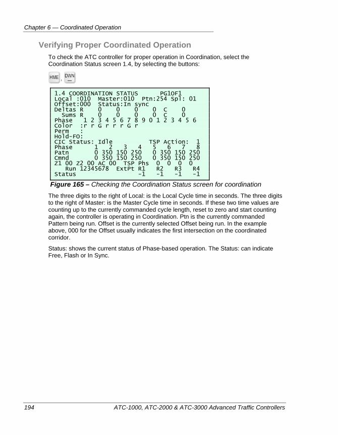
Chapter 6 — Coordinated Operation
194 ATC-1000, ATC-2000 & ATC-3000 Advanced Traffic Controllers
Verifying Proper Coordinated Operation To check the ATC controller for proper operation in Coordination, select the Coordination Status screen 1.4, by selecting the buttons:
,
1.4 COORDINATION STATUS PG1OF1 Local :010 Master:010 Ptn:254 Spl: 01 Offset:000 Status:In sync Deltas R 0 0 0 0 C 0 Sums R 0 0 0 0 C 0 Phase 1 2 3 4 5 6 7 8 9 0 1 2 3 4 5 6 Color :r r G r r r G r Perm : Hold-FO: CIC Status: Idle TSP Action: 1 Phase 1 2 3 4 5 6 7 8 Patn 0 350 150 250 0 350 150 250 Cmnd 0 350 150 250 0 350 150 250 Z1 00 Z2 00 AC 00 TSP Phs 0 0 0 0 Run 12345678 ExtPt R1 R2 R3 R4 Status -1 -1 -1 -1
Figure 165 – Checking the Coordination Status screen for coordination The three digits to the right of Local: is the Local Cycle time in seconds. The three digits to the right of Master: is the Master Cycle time in seconds. If these two time values are counting up to the currently commanded cycle length, reset to zero and start counting again, the controller is operating in Coordination. Ptn is the currently commanded Pattern being run. Offset is the currently selected Offset being run. In the example above, 000 for the Offset usually indicates the first intersection on the coordinated corridor.
Status: shows the current status of Phase-based operation. The Status: can indicate Free, Flash or In Sync.
ATC-1000, ATC-2000 & ATC-3000 Advanced Traffic Controllers 195
Chapter 7 — Interval Operation
This chapter describes the interface and methods used to program an ATC controller for interval-based operation. The following topics are discussed in detail in this chapter:
• Overview of Interval-based operation, on page 196.
• Pattern to Interval Plan mapping, on page 198.
• Using the Interval programming screens, on page 199.
• Details about interval-based preemption, on page 222.
• Setting up Leading or Lagging left turns using interval plans, on page 224.
Chapter 7 — Interval Operation
196 ATC-1000, ATC-2000 & ATC-3000 Advanced Traffic Controllers
OVERVIEW
As has been mentioned elsewhere in this manual, the basic control that determines what timing will be used in an intersection is the pattern number that is currently selected. The bottom 48 patterns are programmed using a NEMA phase-based theory of operation. Patterns 101 through 228, however, are programmed using the interval-based theory of timing an intersection. With the exception of some global parameters and controls that are common to both timing methodologies (such as database management tools, tools to manage the controller clock, time-of-day programming, and I/O port management), almost all programming for interval-based operation occurs in one part of the GREENWave interface, namely on the Interval menu under Programming section of the interface.
(Main Menu > 2.Programming > 7. Interval )
The Interval menu is where the operator goes to define any of the available interval-based patterns, as well as interval-based preemption runs.
Timing Plans There are 32 available timing plans. Each timing plan defines how many intervals will be used in the pattern. A timing plan can use up to 24 intervals. The plan also includes a cycle length, an offset, and a set of split times, one for each of the intervals in the plan.
Signal Plans There are four signal plans available. A signal plan is basically a mapping of the signals and outputs during each interval. The signal plan is the sequence of color indications for all used channel outputs that will appear on the street. The signal plan also includes minimum times for all used intervals and programmable options for each interval covering manual control, transitional control, and semi-actuation of vehicle or pedestrian.
Plan Processing When an interval-based pattern is in effect, the controller starts the associated timing plan, using the associated signal plan signal output assignments for the intervals. The timing plan starts at interval #1 when the controller powers up, or when a new pattern is called. When one interval ends, the next in the sequence starts automatically. Unless options have been set for manual control (such as MCE or Actuated) in the signal plan, the timing plan sequence will only pause at ‘All Red’ intervals. As an example of how the sequence may be paused in a given state, a signal plan may be configured to be ‘Actuated’ so that the interval sequence will rest on main street green until an actuation is received.
Exiting a Timing Plan Sequence Signal plans can be exited at a specified interval so that they can transition either to another signal plan, another timing plan, or to automatic flash.
Interval-based Preemption As with phase-based preemption, there are six available preemption runs when operating an interval-based pattern. (If the controller is running an interval-based pattern
Overview
ATC-1000, ATC-2000 & ATC-3000 Advanced Traffic Controllers 197
and a call comes in on preemption input 2, interval based preemption run 2 will be used. If the controller is running a phase-based pattern, it would run phase-based preemption run #2.) Preemption runs have an entry portion, an optional Track (railroad track clearance) portion, a Dwell portion, and finally an Exit portion. And each Track, Dwell, and Exit portion of each run can have anywhere from 1 to 24 intervals defined.
Calling the Plans How are interval-based plans called into operation? It’s all based on Pattern. When a pattern number between 101 and 228 is called, either by the time of day scheduler, or by a central command or override, each pattern automatically invokes a preset Signal plan and Timing plan. (For example, pattern 101 calls Timing Plan 1 and Signal Plan 1.) These timing plan/signal plan to pattern assignments are hard coded into the ATC controller and are shown in Table 22 on the next page.
Note These assignments are also visible on the ATC front panel interface, along with some additional information, on the Timing Plan > Signal/Offset/Split Data screen. (Main Menu > 2 .Programming > 7 . In terva l > 1 .T iming P lans > 1 .Cyc le / Of fse t / Sp l i t Data ) However, the assignments cannot be modified on these screens.
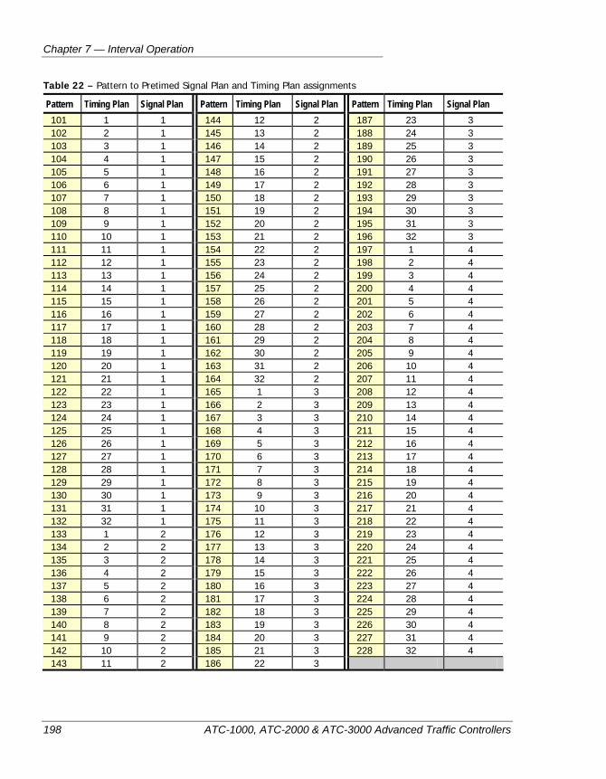
Chapter 7 — Interval Operation
198 ATC-1000, ATC-2000 & ATC-3000 Advanced Traffic Controllers
Table 22 – Pattern to Pretimed Signal Plan and Timing Plan assignments
Pattern Timing Plan Signal Plan Pattern Timing Plan Signal Plan Pattern Timing Plan Signal Plan 101 1 1 144 12 2 187 23 3 102 2 1 145 13 2 188 24 3 103 3 1 146 14 2 189 25 3 104 4 1 147 15 2 190 26 3 105 5 1 148 16 2 191 27 3 106 6 1 149 17 2 192 28 3 107 7 1 150 18 2 193 29 3 108 8 1 151 19 2 194 30 3 109 9 1 152 20 2 195 31 3 110 10 1 153 21 2 196 32 3 111 11 1 154 22 2 197 1 4 112 12 1 155 23 2 198 2 4 113 13 1 156 24 2 199 3 4 114 14 1 157 25 2 200 4 4 115 15 1 158 26 2 201 5 4 116 16 1 159 27 2 202 6 4 117 17 1 160 28 2 203 7 4 118 18 1 161 29 2 204 8 4 119 19 1 162 30 2 205 9 4 120 20 1 163 31 2 206 10 4 121 21 1 164 32 2 207 11 4 122 22 1 165 1 3 208 12 4 123 23 1 166 2 3 209 13 4 124 24 1 167 3 3 210 14 4 125 25 1 168 4 3 211 15 4 126 26 1 169 5 3 212 16 4 127 27 1 170 6 3 213 17 4 128 28 1 171 7 3 214 18 4 129 29 1 172 8 3 215 19 4 130 30 1 173 9 3 216 20 4 131 31 1 174 10 3 217 21 4 132 32 1 175 11 3 218 22 4 133 1 2 176 12 3 219 23 4 134 2 2 177 13 3 220 24 4 135 3 2 178 14 3 221 25 4 136 4 2 179 15 3 222 26 4 137 5 2 180 16 3 223 27 4 138 6 2 181 17 3 224 28 4 139 7 2 182 18 3 225 29 4 140 8 2 183 19 3 226 30 4 141 9 2 184 20 3 227 31 4 142 10 2 185 21 3 228 32 4 143 11 2 186 22 3
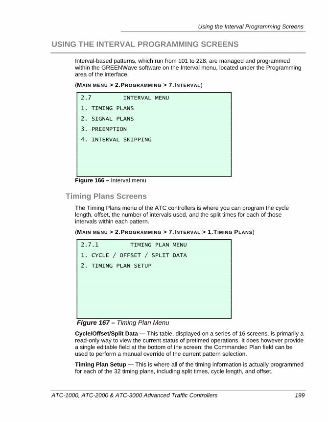
Using the Interval Programming Screens
ATC-1000, ATC-2000 & ATC-3000 Advanced Traffic Controllers 199
USING THE INTERVAL PROGRAMMING SCREENS
Interval-based patterns, which run from 101 to 228, are managed and programmed within the GREENWave software on the Interval menu, located under the Programming area of the interface.
(MAIN MENU > 2.PROGRAMMING > 7.INTERVAL)
2.7 INTERVAL MENU 1. TIMING PLANS 2. SIGNAL PLANS 3. PREEMPTION 4. INTERVAL SKIPPING
Figure 166 – Interval menu
Timing Plans Screens The Timing Plans menu of the ATC controllers is where you can program the cycle length, offset, the number of intervals used, and the split times for each of those intervals within each pattern.
(MAIN MENU > 2.PROGRAMMING > 7.INTERVAL > 1.TIMING PLANS)
2.7.1 TIMING PLAN MENU 1. CYCLE / OFFSET / SPLIT DATA 2. TIMING PLAN SETUP
Figure 167 – Timing Plan Menu Cycle/Offset/Split Data — This table, displayed on a series of 16 screens, is primarily a read-only way to view the current status of pretimed operations. It does however provide a single editable field at the bottom of the screen: the Commanded Plan field can be used to perform a manual override of the current pattern selection.
Timing Plan Setup — This is where all of the timing information is actually programmed for each of the 32 timing plans, including split times, cycle length, and offset.
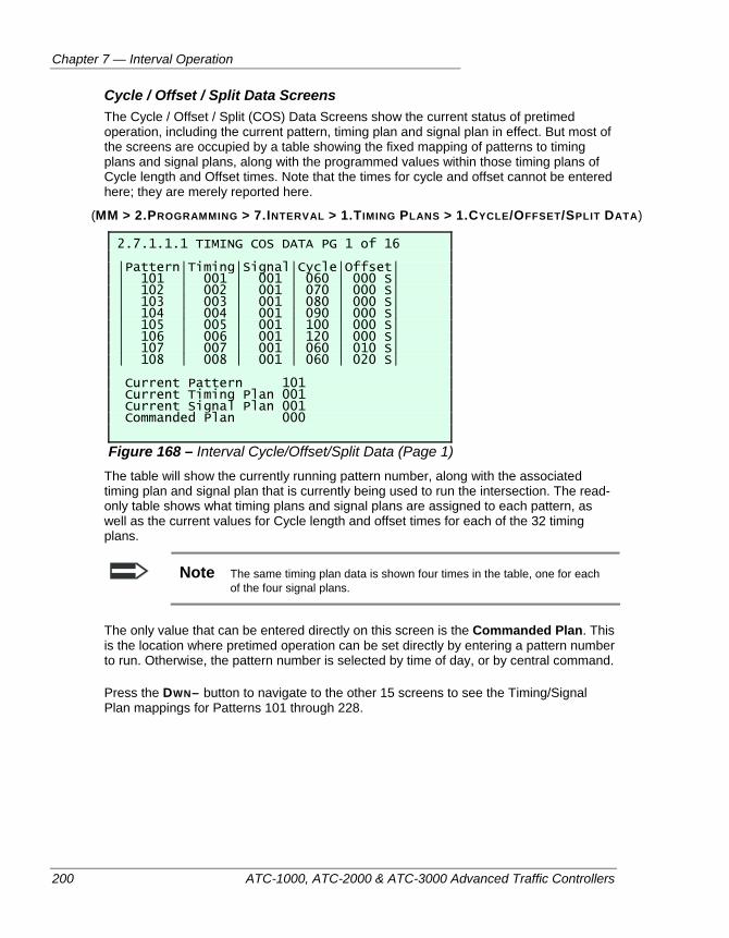
Chapter 7 — Interval Operation
200 ATC-1000, ATC-2000 & ATC-3000 Advanced Traffic Controllers
Cycle / Offset / Split Data Screens The Cycle / Offset / Split (COS) Data Screens show the current status of pretimed operation, including the current pattern, timing plan and signal plan in effect. But most of the screens are occupied by a table showing the fixed mapping of patterns to timing plans and signal plans, along with the programmed values within those timing plans of Cycle length and Offset times. Note that the times for cycle and offset cannot be entered here; they are merely reported here.
(MM > 2.PROGRAMMING > 7.INTERVAL > 1.TIMING PLANS > 1.CYCLE/OFFSET/SPLIT DATA)
2.7.1.1.1 TIMING COS DATA PG 1 of 16 |Pattern|Timing|Signal|Cycle|Offset| | 101 | 001 | 001 | 060 | 000 S| | 102 | 002 | 001 | 070 | 000 S| | 103 | 003 | 001 | 080 | 000 S| | 104 | 004 | 001 | 090 | 000 S| | 105 | 005 | 001 | 100 | 000 S| | 106 | 006 | 001 | 120 | 000 S| | 107 | 007 | 001 | 060 | 010 S| | 108 | 008 | 001 | 060 | 020 S| Current Pattern 101 Current Timing Plan 001 Current Signal Plan 001 Commanded Plan 000
Figure 168 – Interval Cycle/Offset/Split Data (Page 1) The table will show the currently running pattern number, along with the associated timing plan and signal plan that is currently being used to run the intersection. The read-only table shows what timing plans and signal plans are assigned to each pattern, as well as the current values for Cycle length and offset times for each of the 32 timing plans.
Note The same timing plan data is shown four times in the table, one for each of the four signal plans.
The only value that can be entered directly on this screen is the Commanded Plan. This is the location where pretimed operation can be set directly by entering a pattern number to run. Otherwise, the pattern number is selected by time of day, or by central command.
Press the DWN– button to navigate to the other 15 screens to see the Timing/Signal Plan mappings for Patterns 101 through 228.
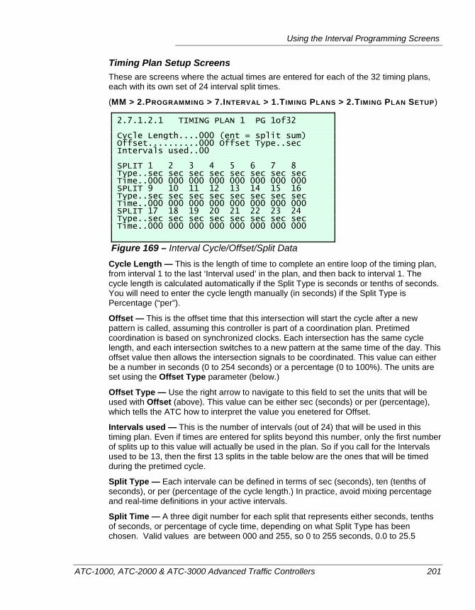
Using the Interval Programming Screens
ATC-1000, ATC-2000 & ATC-3000 Advanced Traffic Controllers 201
Timing Plan Setup Screens These are screens where the actual times are entered for each of the 32 timing plans, each with its own set of 24 interval split times.
(MM > 2.PROGRAMMING > 7.INTERVAL > 1.TIMING PLANS > 2.TIMING PLAN SETUP)
2.7.1.2.1 TIMING PLAN 1 PG 1of32 Cycle Length....000 (ent = split sum) Offset..........000 Offset Type..sec Intervals used..00 SPLIT 1 2 3 4 5 6 7 8 Type..sec sec sec sec sec sec sec sec Time..000 000 000 000 000 000 000 000 SPLIT 9 10 11 12 13 14 15 16 Type..sec sec sec sec sec sec sec sec Time..000 000 000 000 000 000 000 000 SPLIT 17 18 19 20 21 22 23 24 Type..sec sec sec sec sec sec sec sec Time..000 000 000 000 000 000 000 000
Figure 169 – Interval Cycle/Offset/Split Data Cycle Length — This is the length of time to complete an entire loop of the timing plan, from interval 1 to the last ‘Interval used’ in the plan, and then back to interval 1. The cycle length is calculated automatically if the Split Type is seconds or tenths of seconds. You will need to enter the cycle length manually (in seconds) if the Split Type is Percentage (“per”).
Offset — This is the offset time that this intersection will start the cycle after a new pattern is called, assuming this controller is part of a coordination plan. Pretimed coordination is based on synchronized clocks. Each intersection has the same cycle length, and each intersection switches to a new pattern at the same time of the day. This offset value then allows the intersection signals to be coordinated. This value can either be a number in seconds (0 to 254 seconds) or a percentage (0 to 100%). The units are set using the Offset Type parameter (below.)
Offset Type — Use the right arrow to navigate to this field to set the units that will be used with Offset (above). This value can be either sec (seconds) or per (percentage), which tells the ATC how to interpret the value you enetered for Offset.
Intervals used — This is the number of intervals (out of 24) that will be used in this timing plan. Even if times are entered for splits beyond this number, only the first number of splits up to this value will actually be used in the plan. So if you call for the Intervals used to be 13, then the first 13 splits in the table below are the ones that will be timed during the pretimed cycle.
Split Type — Each intervale can be defined in terms of sec (seconds), ten (tenths of seconds), or per (percentage of the cycle length.) In practice, avoid mixing percentage and real-time definitions in your active intervals.
Split Time — A three digit number for each split that represents either seconds, tenths of seconds, or percentage of cycle time, depending on what Split Type has been chosen. Valid values are between 000 and 255, so 0 to 255 seconds, 0.0 to 25.5
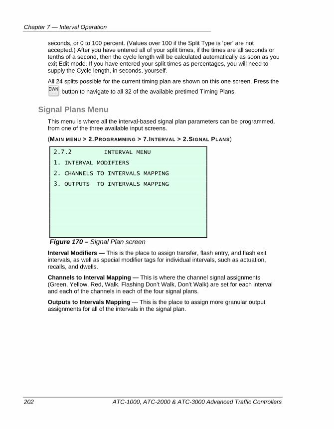
Chapter 7 — Interval Operation
202 ATC-1000, ATC-2000 & ATC-3000 Advanced Traffic Controllers
seconds, or 0 to 100 percent. (Values over 100 if the Split Type is ‘per’ are not accepted.) After you have entered all of your split times, if the times are all seconds or tenths of a second, then the cycle length will be calculated automatically as soon as you exit Edit mode. If you have entered your split times as percentages, you will need to supply the Cycle length, in seconds, yourself.
All 24 splits possible for the current timing plan are shown on this one screen. Press the
button to navigate to all 32 of the available pretimed Timing Plans.
Signal Plans Menu This menu is where all the interval-based signal plan parameters can be programmed, from one of the three available input screens.
(MAIN MENU > 2.PROGRAMMING > 7.INTERVAL > 2.SIGNAL PLANS)
2.7.2 INTERVAL MENU 1. INTERVAL MODIFIERS 2. CHANNELS TO INTERVALS MAPPING 3. OUTPUTS TO INTERVALS MAPPING
Figure 170 – Signal Plan screen Interval Modifiers — This is the place to assign transfer, flash entry, and flash exit intervals, as well as special modifier tags for individual intervals, such as actuation, recalls, and dwells.
Channels to Interval Mapping — This is where the channel signal assignments (Green, Yellow, Red, Walk, Flashing Don’t Walk, Don’t Walk) are set for each interval and each of the channels in each of the four signal plans.
Outputs to Intervals Mapping — This is the place to assign more granular output assignments for all of the intervals in the signal plan.
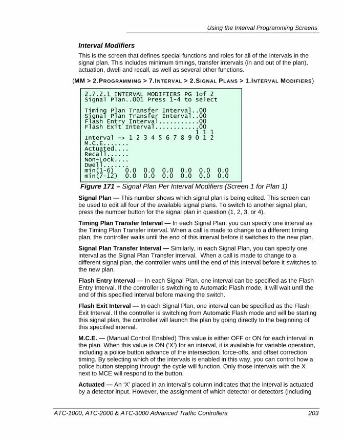
Using the Interval Programming Screens
ATC-1000, ATC-2000 & ATC-3000 Advanced Traffic Controllers 203
Interval Modifiers This is the screen that defines special functions and roles for all of the intervals in the signal plan. This includes minimum timings, transfer intervals (in and out of the plan), actuation, dwell and recall, as well as several other functions.
(MM > 2.PROGRAMMING > 7.INTERVAL > 2.SIGNAL PLANS > 1.INTERVAL MODIFIERS)
2.7.2.1 INTERVAL MODIFIERS PG 1of 2 Signal Plan..001 Press 1-4 to select Timing Plan Transfer Interval..00 Signal Plan Transfer Interval..00 Flash Entry Interval...........00 Flash Exit Interval............00 1 1 1 Interval -> 1 2 3 4 5 6 7 8 9 0 1 2 M.C.E....... Actuated.... Recall...... Non-Lock.... Dwell....... min(1-6) 0.0 0.0 0.0 0.0 0.0 0.0 min(7-12) 0.0 0.0 0.0 0.0 0.0 0.0
Figure 171 – Signal Plan Per Interval Modifiers (Screen 1 for Plan 1) Signal Plan — This number shows which signal plan is being edited. This screen can be used to edit all four of the available signal plans. To switch to another signal plan, press the number button for the signal plan in question (1, 2, 3, or 4).
Timing Plan Transfer Interval — In each Signal Plan, you can specify one interval as the Timing Plan Transfer interval. When a call is made to change to a different timing plan, the controller waits until the end of this interval before it switches to the new plan.
Signal Plan Transfer Interval — Similarly, in each Signal Plan, you can specify one interval as the Signal Plan Transfer interval. When a call is made to change to a different signal plan, the controller waits until the end of this interval before it switches to the new plan.
Flash Entry Interval — In each Signal Plan, one interval can be specified as the Flash Entry Interval. If the controller is switching to Automatic Flash mode, it will wait until the end of this specified interval before making the switch.
Flash Exit Interval — In each Signal Plan, one interval can be specified as the Flash Exit Interval. If the controller is switching from Automatic Flash mode and will be starting this signal plan, the controller will launch the plan by going directly to the beginning of this specified interval.
M.C.E. — (Manual Control Enabled) This value is either OFF or ON for each interval in the plan. When this value is ON (‘X’) for an interval, it is available for variable operation, including a police button advance of the intersection, force-offs, and offset correction timing. By selecting which of the intervals is enabled in this way, you can control how a police button stepping through the cycle will function. Only those intervals with the X next to MCE will respond to the button.
Actuated — An ‘X’ placed in an interval’s column indicates that the interval is actuated by a detector input. However, the assignment of which detector or detectors (including
Chapter 7 — Interval Operation
204 ATC-1000, ATC-2000 & ATC-3000 Advanced Traffic Controllers
pedestrian detectors) will cause this actuation is not available from the controller front panel in build 304 of the firmware. To make the detector assignment for each interval, you will need to edit the device database using ATCLink or IQ Central.
Recall — When checked, it indicates that an interval MUST be serviced during the cycle. In effect, this is an artificial call on that interval ; one that isn’t being generated by a detector input.
Non-Lock — By default, intervals are locking on detector inputs, meaning that if a call is placed (and the interval is ‘Actuated’), then the demand for service on that interval remains, even if the call goes away. If you set Non-Lock to ON (‘X’), then this interval’s detectors do not latch in this manner, meaning that if the call goes away, then the demand for service on this interval also goes away.
Note Pedestrian detector calls are always locking, no matter how the Non-Lock parameter is set.
Dwell — An interval marked as Dwell is used by the traffic engine to get the intersection back into coordination. Since pretimed operation does not have other methods for coordination offset recovery, Dwell is the only option available for the coordinator to modify the cycle time in order to resynchronize the intersection with the coordination timing. Typically, only one interval is marked as the Dwell interval, and it’s usually the interval that supplies the Green light to the main traffic artery. However, the ATC firmware will allow multiple intervals to be available for Dwell operation. If more than one are checked (‘X’), and the coordinator needs to Dwell to resync coordination, then it will use the first interval encountered that has the Dwell function flagged.
Note If no Dwell inerval is programmed, the controller will never get into step.
min — These are the minimum times required for each interval. Valid values can be anything from 0.0 to 25.5 seconds. This is typically used to protect a minimum time for the amber (yellow) portion of a cycle to prevent it from falling below the legal limit for that signal (This is 3.0 seconds in the United States, but the operator can set this minimum to any value in the range mentioned previously.) As of build 304 of the controller firmware, the only function that may potentially shorten an interval, and which must be protected against using this min value, is Transit Signal Priority (TSP) operation. TSP can shorten some intervals in order to recover after a transit vehicle has taken priority in the intersection and knocked the intersection out of coordination.
The Pre-timed Interval Modifiers area forms a 4 x 2 array of screens. Press the numbers
1 through 4 to see the four signal plan screens, and press the button to see the modifiers for intervals 13 through 24 for each plan.
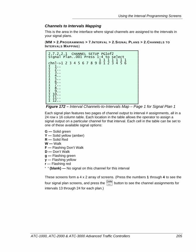
Using the Interval Programming Screens
ATC-1000, ATC-2000 & ATC-3000 Advanced Traffic Controllers 205
Channels to Intervals Mapping This is the area in the interface where signal channels are assigned to the intervals in your signal plans.
(MM > 2.PROGRAMMING > 7.INTERVAL > 2.SIGNAL PLANS > 2.CHANNELS TO INTERVALS MAPPING)
2.7.2.2.1 CHANNEL SETUP PG1of2 Signal Plan..001 Press 1-4 to select 1 1 1 1 1 1 1 chnl->1 2 3 4 5 6 7 8 9 0 1 2 3 4 5 6 I 1.. I 2.. I 3.. I 4.. I 5.. I 6.. I 7.. I 8.. I 9.. I 10.. I 11.. I 12..
Figure 172 – Interval Channels-to-Intervals Map – Page 1 for Signal Plan 1 Each signal plan features two pages of channel output to interval # assignments, all in a 24 row x 16 column table. Each location in the table allows the operator to assign a signal output on a particular channel for that interval. Each cell in the table can be set to one of these available signal options:
G — Solid green Y — Solid yellow (amber) R — Solid Red W — Walk F — Flashing Don’t Walk D — Don’t Walk g — Flashing green y — Flashing yellow r — Flashing red ‘ ‘ (blank) — No signal on this channel for this interval
These screens form a 4 x 2 array of screens. (Press the numbers 1 through 4 to see the
four signal plan screens, and press the button to see the channel assignments for intervals 13 through 24 for each plan.)
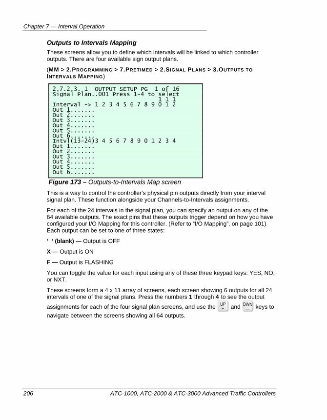
Chapter 7 — Interval Operation
206 ATC-1000, ATC-2000 & ATC-3000 Advanced Traffic Controllers
Outputs to Intervals Mapping These screens allow you to define which intervals will be linked to which controller outputs. There are four available sign output plans.
(MM > 2.PROGRAMMING > 7.PRETIMED > 2.SIGNAL PLANS > 3.OUTPUTS TO INTERVALS MAPPING)
2.7.2.3. 1 OUTPUT SETUP PG 1 of 16 Signal Plan..001 Press 1-4 to select 1 1 1 Interval -> 1 2 3 4 5 6 7 8 9 0 1 2 Out 1....... Out 2....... Out 3....... Out 4....... Out 5....... Out 6....... Intvl(13-24)3 4 5 6 7 8 9 0 1 2 3 4 Out 1....... Out 2....... Out 3....... Out 4....... Out 5....... Out 6.......
Figure 173 – Outputs-to-Intervals Map screen This is a way to control the controller’s physical pin outputs directly from your interval signal plan. These function alongside your Channels-to-Intervals assignments.
For each of the 24 intervals in the signal plan, you can specify an output on any of the 64 available outputs. The exact pins that these outputs trigger depend on how you have configured your I/O Mapping for this controller. (Refer to “I/O Mapping”, on page 101) Each output can be set to one of three states:
‘ ‘ (blank) — Output is OFF
X — Output is ON
F — Output is FLASHING
You can toggle the value for each input using any of these three keypad keys: YES, NO, or NXT.
These screens form a 4 x 11 array of screens, each screen showing 6 outputs for all 24 intervals of one of the signal plans. Press the numbers 1 through 4 to see the output
assignments for each of the four signal plan screens, and use the and keys to navigate between the screens showing all 64 outputs.
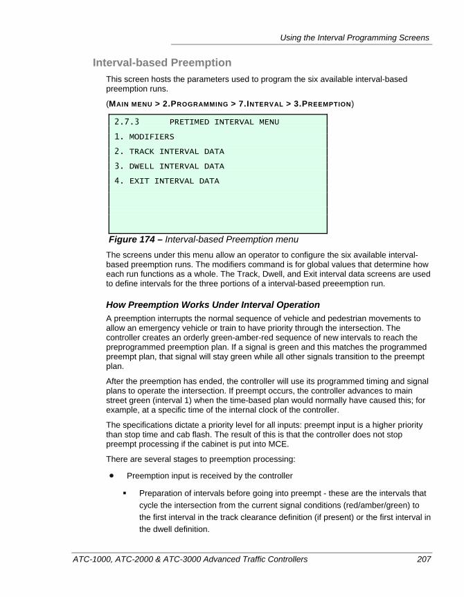
Using the Interval Programming Screens
ATC-1000, ATC-2000 & ATC-3000 Advanced Traffic Controllers 207
Interval-based Preemption This screen hosts the parameters used to program the six available interval-based preemption runs.
(MAIN MENU > 2.PROGRAMMING > 7.INTERVAL > 3.PREEMPTION)
2.7.3 PRETIMED INTERVAL MENU 1. MODIFIERS 2. TRACK INTERVAL DATA 3. DWELL INTERVAL DATA 4. EXIT INTERVAL DATA
Figure 174 – Interval-based Preemption menu The screens under this menu allow an operator to configure the six available interval-based preemption runs. The modifiers command is for global values that determine how each run functions as a whole. The Track, Dwell, and Exit interval data screens are used to define intervals for the three portions of a interval-based preeemption run.
How Preemption Works Under Interval Operation A preemption interrupts the normal sequence of vehicle and pedestrian movements to allow an emergency vehicle or train to have priority through the intersection. The controller creates an orderly green-amber-red sequence of new intervals to reach the preprogrammed preemption plan. If a signal is green and this matches the programmed preempt plan, that signal will stay green while all other signals transition to the preempt plan.
After the preemption has ended, the controller will use its programmed timing and signal plans to operate the intersection. If preempt occurs, the controller advances to main street green (interval 1) when the time-based plan would normally have caused this; for example, at a specific time of the internal clock of the controller.
The specifications dictate a priority level for all inputs: preempt input is a higher priority than stop time and cab flash. The result of this is that the controller does not stop preempt processing if the cabinet is put into MCE.
There are several stages to preemption processing:
Preemption input is received by the controller
Preparation of intervals before going into preempt - these are the intervals that cycle the intersection from the current signal conditions (red/amber/green) to the first interval in the track clearance definition (if present) or the first interval in the dwell definition.
Chapter 7 — Interval Operation
208 ATC-1000, ATC-2000 & ATC-3000 Advanced Traffic Controllers
The controller uses default times for these new intervals (three seconds for amber, two seconds for red, and three seconds for flashing Don’t Walk). These times can be changed on the Interval Skipping screen, available on the Interval menu of the ATC interface. This screen has entries for pedestrian clearance, amber clearance, and red time for each channel.
Preempt Track Clearance intervals - These intervals are optional and are often used for handling train crossings, but they can be used for other purposes. If they are not configured, then the first interval run during the actual preempt will be the first dwell interval that follows. If a road crosses a railroad track, a track clearance interval would need to be defined so that the road can be cleared before the train comes through.
Preempt Dwell stage intervals - these are the actual intervals that run during preempt. These intervals give priority to emergency vehicles.
Preempt Exit stage intervals - After the dwell times are completed, these intervals return the intersection to normal operation. Typically, normal operation starts in Interval 1 so the controller will appear to dwell in the last preempt interval until the proper coordinated time is ready to advance to Interval 1. (Assuming Interval 1 is programmed as the Dwell interval.) This advance to Interval 1 is the TBC time as determined by the controller’s clock and the current timing plan. Because of this dwell it may appear that the controller has hung. The controller will return to Interval 1 at the same coordinated time, as if the preemption did not occur.
Flashing in Dwell It is possible to configure preempt to flash the dwell intervals. By using the preempt option to cycle the dwell phases and having two alternate intervals of one half second each, the intersection can be doing a flash sequence while in preemption. In the example ATCLink preemption configuration screen shown below, channels 1 and 5 are flashing red simultaneously with channels 2 and 6, which are flashing yellow. Channels 3, 4, 7, and 8 will flash red, but on the alternate half of the 30 second in a wig-wag fashion.
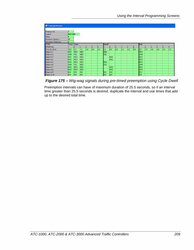
Using the Interval Programming Screens
ATC-1000, ATC-2000 & ATC-3000 Advanced Traffic Controllers 209
Figure 175 – Wig-wag signals during pre-timed preemption using Cycle Dwell
Preemption intervals can have of maximum duration of 25.5 seconds, so if an interval time greater than 25.5 seconds is desired, duplicate the interval and use times that add up to the desired total time.
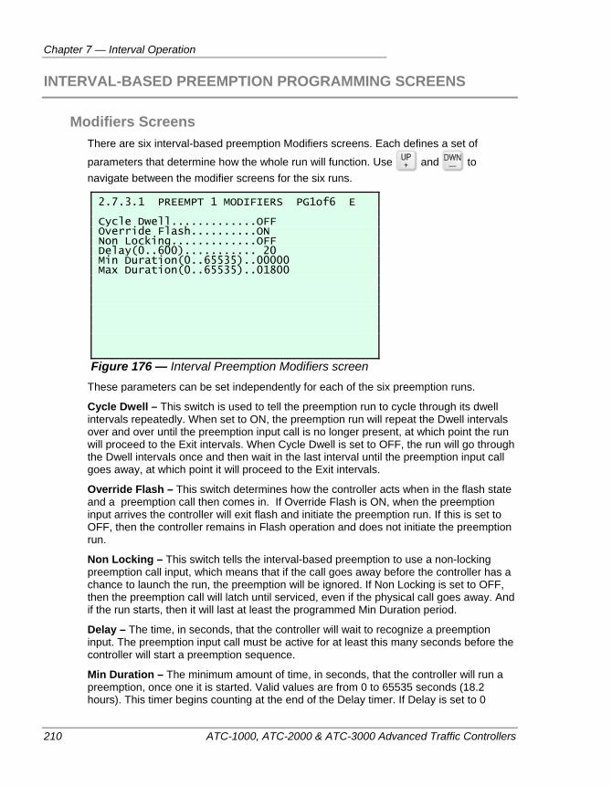
Chapter 7 — Interval Operation
210 ATC-1000, ATC-2000 & ATC-3000 Advanced Traffic Controllers
INTERVAL-BASED PREEMPTION PROGRAMMING SCREENS
Modifiers Screens There are six interval-based preemption Modifiers screens. Each defines a set of
parameters that determine how the whole run will function. Use and to navigate between the modifier screens for the six runs.
2.7.3.1 PREEMPT 1 MODIFIERS PG1of6 E Cycle Dwell.............OFF Override Flash..........ON Non Locking.............OFF Delay(0..600)........... 20 Min Duration(0..65535)..00000 Max Duration(0..65535)..01800
Figure 176 — Interval Preemption Modifiers screen These parameters can be set independently for each of the six preemption runs.
Cycle Dwell – This switch is used to tell the preemption run to cycle through its dwell intervals repeatedly. When set to ON, the preemption run will repeat the Dwell intervals over and over until the preemption input call is no longer present, at which point the run will proceed to the Exit intervals. When Cycle Dwell is set to OFF, the run will go through the Dwell intervals once and then wait in the last interval until the preemption input call goes away, at which point it will proceed to the Exit intervals.
Override Flash – This switch determines how the controller acts when in the flash state and a preemption call then comes in. If Override Flash is ON, when the preemption input arrives the controller will exit flash and initiate the preemption run. If this is set to OFF, then the controller remains in Flash operation and does not initiate the preemption run.
Non Locking – This switch tells the interval-based preemption to use a non-locking preemption call input, which means that if the call goes away before the controller has a chance to launch the run, the preemption will be ignored. If Non Locking is set to OFF, then the preemption call will latch until serviced, even if the physical call goes away. And if the run starts, then it will last at least the programmed Min Duration period.
Delay – The time, in seconds, that the controller will wait to recognize a preemption input. The preemption input call must be active for at least this many seconds before the controller will start a preemption sequence.
Min Duration – The minimum amount of time, in seconds, that the controller will run a preemption, once one it is started. Valid values are from 0 to 65535 seconds (18.2 hours). This timer begins counting at the end of the Delay timer. If Delay is set to 0
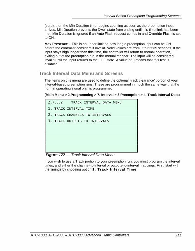
Interval-Based Preemption Programming Screens
ATC-1000, ATC-2000 & ATC-3000 Advanced Traffic Controllers 211
(zero), then the Min Duration timer begins counting as soon as the preemption input arrives. Min Duration prevents the Dwell state from ending until this time limit has been met. Min Duration is ignored if an Auto Flash request comes in and Override Flash is set to ON.
Max Presence – This is an upper limit on how long a preemption input can be ON before the controller considers it invalid. Valid values are from 0 to 65535 seconds. If the input stays high longer than this time, the controller will return to normal operation, exiting out of the preemption run in the normal manner. The input will be considered invalid until the input returns to the OFF state. A value of 0 means that this test is disabled.
Track Interval Data Menu and Screens The items on this menu are used to define the optional ‘track clearance’ portion of your interval-based preemption runs. These are programmed in much the same way that the normal operating signal plan is programmed.
(Main Menu > 2.Programming > 7. Interval > 3.Preemption > 4. Track Interval Data)
2.7.3.2 TRACK INTERVAL DATA MENU 1. TRACK INTERVAL TIME 2. TRACK CHANNELS TO INTERVALS 3. TRACK OUTPUTS TO INTERVALS
Figure 177 — Track Interval Data Menu If you wish to use a Track portion to your preemption run, you must program the interval times, and either the channel-to-interval or outputs-to-interval mappings. First, start with the timings by choosing option 1. Track Interval T ime .
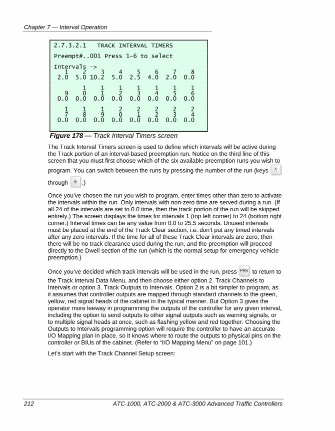
Chapter 7 — Interval Operation
212 ATC-1000, ATC-2000 & ATC-3000 Advanced Traffic Controllers
2.7.3.2.1 TRACK INTERVAL TIMERS Preempt#..001 Press 1-6 to select Intervals -> 1 2 3 4 5 6 7 8 2.0 5.0 10.2 5.0 2.5 4.0 2.0 0.0 1 1 1 1 1 1 1 9 0 1 2 3 4 5 6 0.0 0.0 0.0 0.0 0.0 0.0 0.0 0.0 1 1 1 2 2 2 2 2 7 8 9 0 1 2 3 4 0.0 0.0 0.0 0.0 0.0 0.0 0.0 0.0
Figure 178 — Track Interval Timers screen The Track Interval Timers screen is used to define which intervals will be active during the Track portion of an interval-based preemption run. Notice on the third line of this screen that you must first choose which of the six available preemption runs you wish to program. You can switch between the runs by pressing the number of the run (keys
through .)
Once you’ve chosen the run you wish to program, enter times other than zero to activate the intervals within the run. Only intervals with non-zero time are served during a run. (If all 24 of the intervals are set to 0.0 time, then the track portion of the run will be skipped entirely.) The screen displays the times for intervals 1 (top left corner) to 24 (bottom right corner.) Interval times can be any value from 0.0 to 25.5 seconds. Unused intervals must be placed at the end of the Track Clear section, i.e. don’t put any timed intervals after any zero intervals. If the time for all of these Track Clear intervals are zero, then there will be no track clearance used during the run, and the preemption will proceed directly to the Dwell section of the run (which is the normal setup for emergency vehicle preemption.)
Once you’ve decided which track intervals will be used in the run, press to return to the Track Interval Data Menu, and then choose either option 2. Track Channels to Intervals or option 3. Track Outputs to Intervals. Option 2 is a bit simpler to program, as it assumes that controller outputs are mapped through standard channels to the green, yellow, red signal heads of the cabinet in the typical manner. But Option 3 gives the operator more leeway in programming the outputs of the controller for any given interval, including the option to send outputs to other signal outputs such as warning signals, or to multiple signal heads at once, such as flashing yellow and red together. Choosing the Outputs to Intervals programming option will require the controller to have an accurate I/O Mapping plan in place, so it knows where to route the outputs to physical pins on the controller or BIUs of the cabinet. (Refer to “I/O Mapping Menu” on page 101.)
Let’s start with the Track Channel Setup screen:
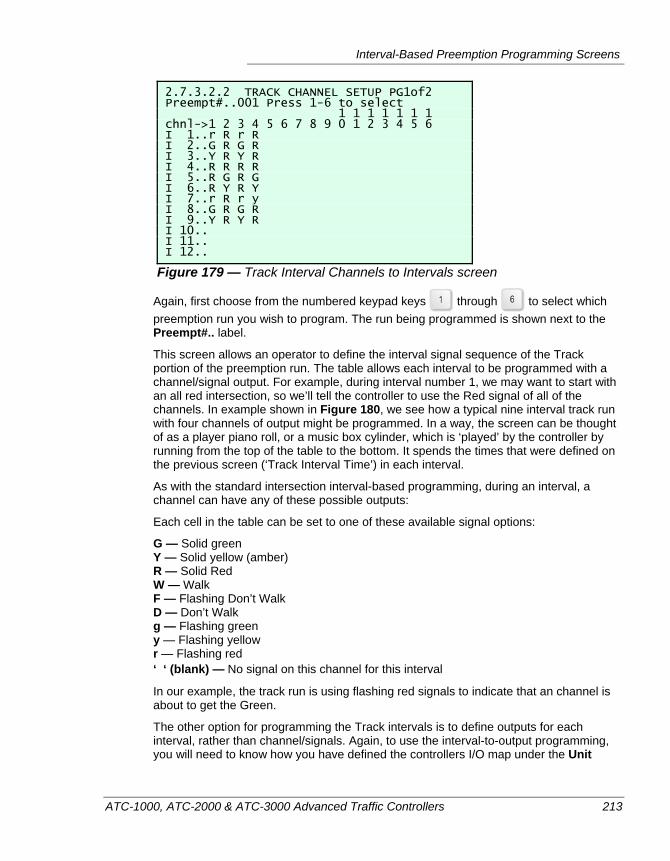
Interval-Based Preemption Programming Screens
ATC-1000, ATC-2000 & ATC-3000 Advanced Traffic Controllers 213
2.7.3.2.2 TRACK CHANNEL SETUP PG1of2 Preempt#..001 Press 1-6 to select 1 1 1 1 1 1 1 chnl->1 2 3 4 5 6 7 8 9 0 1 2 3 4 5 6 I 1..r R r R I 2..G R G R I 3..Y R Y R I 4..R R R R I 5..R G R G I 6..R Y R Y I 7..r R r y I 8..G R G R I 9..Y R Y R I 10.. I 11.. I 12..
Figure 179 — Track Interval Channels to Intervals screen
Again, first choose from the numbered keypad keys through to select which preemption run you wish to program. The run being programmed is shown next to the Preempt#.. label.
This screen allows an operator to define the interval signal sequence of the Track portion of the preemption run. The table allows each interval to be programmed with a channel/signal output. For example, during interval number 1, we may want to start with an all red intersection, so we’ll tell the controller to use the Red signal of all of the channels. In example shown in Figure 180, we see how a typical nine interval track run with four channels of output might be programmed. In a way, the screen can be thought of as a player piano roll, or a music box cylinder, which is ‘played’ by the controller by running from the top of the table to the bottom. It spends the times that were defined on the previous screen (‘Track Interval Time’) in each interval.
As with the standard intersection interval-based programming, during an interval, a channel can have any of these possible outputs:
Each cell in the table can be set to one of these available signal options:
G — Solid green Y — Solid yellow (amber) R — Solid Red W — Walk F — Flashing Don’t Walk D — Don’t Walk g — Flashing green y — Flashing yellow r — Flashing red ‘ ‘ (blank) — No signal on this channel for this interval
In our example, the track run is using flashing red signals to indicate that an channel is about to get the Green.
The other option for programming the Track intervals is to define outputs for each interval, rather than channel/signals. Again, to use the interval-to-output programming, you will need to know how you have defined the controllers I/O map under the Unit
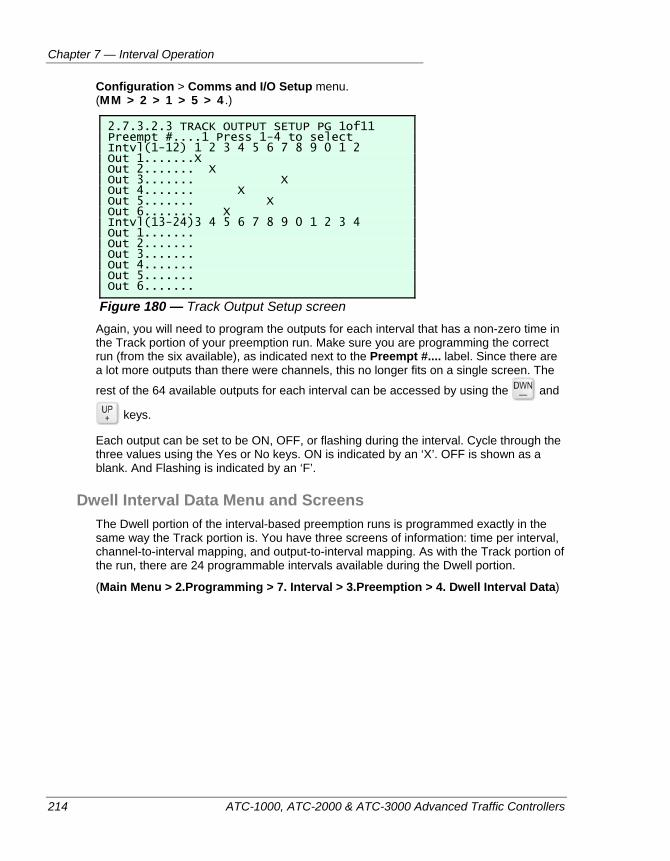
Chapter 7 — Interval Operation
214 ATC-1000, ATC-2000 & ATC-3000 Advanced Traffic Controllers
Configuration > Comms and I/O Setup menu. (MM > 2 > 1 > 5 > 4 .)
2.7.3.2.3 TRACK OUTPUT SETUP PG 1of11 Preempt #....1 Press 1-4 to select Intvl(1-12) 1 2 3 4 5 6 7 8 9 0 1 2 Out 1.......X Out 2....... X Out 3....... X Out 4....... X Out 5....... X Out 6....... X Intvl(13-24)3 4 5 6 7 8 9 0 1 2 3 4 Out 1....... Out 2....... Out 3....... Out 4....... Out 5....... Out 6.......
Figure 180 — Track Output Setup screen Again, you will need to program the outputs for each interval that has a non-zero time in the Track portion of your preemption run. Make sure you are programming the correct run (from the six available), as indicated next to the Preempt #.... label. Since there are a lot more outputs than there were channels, this no longer fits on a single screen. The
rest of the 64 available outputs for each interval can be accessed by using the and
keys.
Each output can be set to be ON, OFF, or flashing during the interval. Cycle through the three values using the Yes or No keys. ON is indicated by an ‘X’. OFF is shown as a blank. And Flashing is indicated by an ‘F’.
Dwell Interval Data Menu and Screens The Dwell portion of the interval-based preemption runs is programmed exactly in the same way the Track portion is. You have three screens of information: time per interval, channel-to-interval mapping, and output-to-interval mapping. As with the Track portion of the run, there are 24 programmable intervals available during the Dwell portion.
(Main Menu > 2.Programming > 7. Interval > 3.Preemption > 4. Dwell Interval Data)
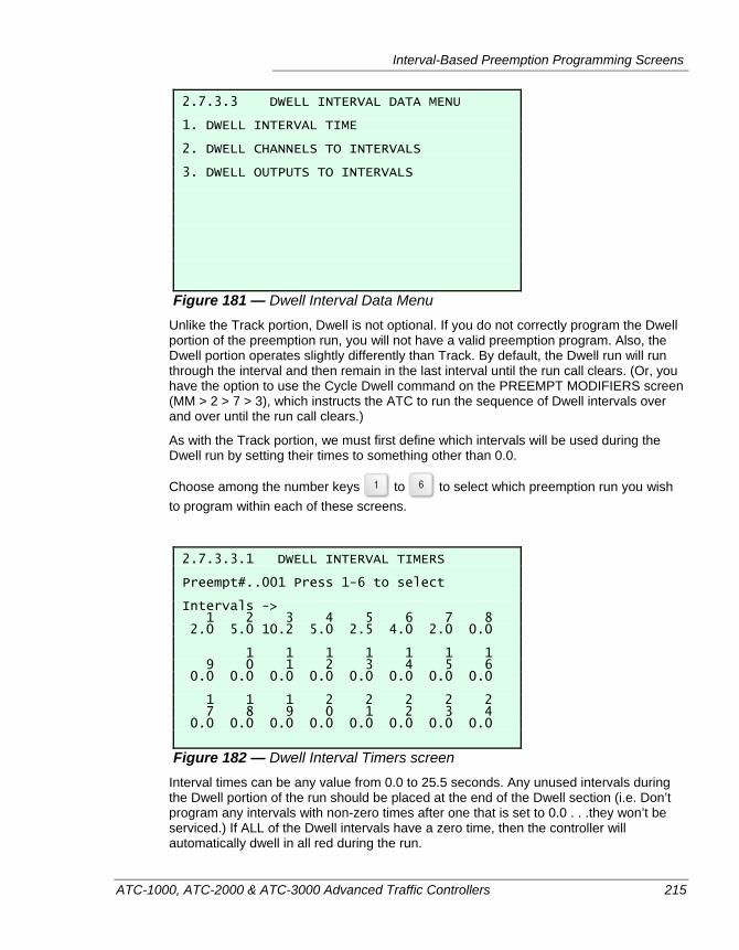
Interval-Based Preemption Programming Screens
ATC-1000, ATC-2000 & ATC-3000 Advanced Traffic Controllers 215
2.7.3.3 DWELL INTERVAL DATA MENU 1. DWELL INTERVAL TIME 2. DWELL CHANNELS TO INTERVALS 3. DWELL OUTPUTS TO INTERVALS
Figure 181 — Dwell Interval Data Menu Unlike the Track portion, Dwell is not optional. If you do not correctly program the Dwell portion of the preemption run, you will not have a valid preemption program. Also, the Dwell portion operates slightly differently than Track. By default, the Dwell run will run through the interval and then remain in the last interval until the run call clears. (Or, you have the option to use the Cycle Dwell command on the PREEMPT MODIFIERS screen (MM > 2 > 7 > 3), which instructs the ATC to run the sequence of Dwell intervals over and over until the run call clears.)
As with the Track portion, we must first define which intervals will be used during the Dwell run by setting their times to something other than 0.0.
Choose among the number keys to to select which preemption run you wish to program within each of these screens.
2.7.3.3.1 DWELL INTERVAL TIMERS Preempt#..001 Press 1-6 to select Intervals -> 1 2 3 4 5 6 7 8 2.0 5.0 10.2 5.0 2.5 4.0 2.0 0.0 1 1 1 1 1 1 1 9 0 1 2 3 4 5 6 0.0 0.0 0.0 0.0 0.0 0.0 0.0 0.0 1 1 1 2 2 2 2 2 7 8 9 0 1 2 3 4 0.0 0.0 0.0 0.0 0.0 0.0 0.0 0.0
Figure 182 — Dwell Interval Timers screen Interval times can be any value from 0.0 to 25.5 seconds. Any unused intervals during the Dwell portion of the run should be placed at the end of the Dwell section (i.e. Don’t program any intervals with non-zero times after one that is set to 0.0 . . .they won’t be serviced.) If ALL of the Dwell intervals have a zero time, then the controller will automatically dwell in all red during the run.
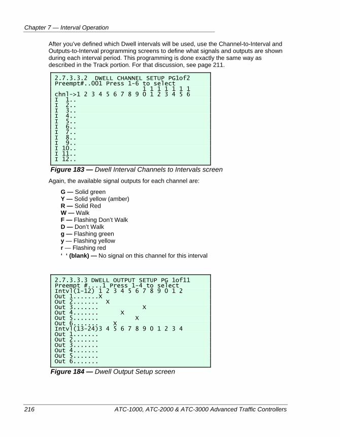
Chapter 7 — Interval Operation
216 ATC-1000, ATC-2000 & ATC-3000 Advanced Traffic Controllers
After you’ve defined which Dwell intervals will be used, use the Channel-to-Interval and Outputs-to-Interval programming screens to define what signals and outputs are shown during each interval period. This programming is done exactly the same way as described in the Track portion. For that discussion, see page 211.
2.7.3.3.2 DWELL CHANNEL SETUP PG1of2 Preempt#..001 Press 1-6 to select 1 1 1 1 1 1 1 chnl->1 2 3 4 5 6 7 8 9 0 1 2 3 4 5 6 I 1.. I 2.. I 3.. I 4.. I 5.. I 6.. I 7.. I 8.. I 9.. I 10.. I 11.. I 12..
Figure 183 — Dwell Interval Channels to Intervals screen Again, the available signal outputs for each channel are:
G — Solid green Y — Solid yellow (amber) R — Solid Red W — Walk F — Flashing Don’t Walk D — Don’t Walk g — Flashing green y — Flashing yellow r — Flashing red ‘ ‘ (blank) — No signal on this channel for this interval
2.7.3.3.3 DWELL OUTPUT SETUP PG 1of11 Preempt #....1 Press 1-4 to select Intvl(1-12) 1 2 3 4 5 6 7 8 9 0 1 2 Out 1.......X Out 2....... X Out 3....... X Out 4....... X Out 5....... X Out 6....... X Intvl(13-24)3 4 5 6 7 8 9 0 1 2 3 4 Out 1....... Out 2....... Out 3....... Out 4....... Out 5....... Out 6.......
Figure 184 — Dwell Output Setup screen
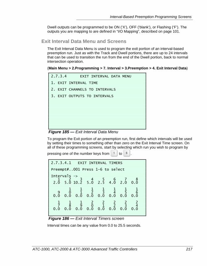
Interval-Based Preemption Programming Screens
ATC-1000, ATC-2000 & ATC-3000 Advanced Traffic Controllers 217
Dwell outputs can be programmed to be ON (‘X’), OFF (‘blank’), or Flashing (‘F’). The outputs you are mapping to are defined in “I/O Mapping”, described on page 101.
Exit Interval Data Menu and Screens The Exit Interval Data Menu is used to program the exit portion of an interval-based preemption run. Just as with the Track and Dwell portions, there are up to 24 intervals that can be used to transition the run from the end of the Dwell portion, back to normal intersection operation.
(Main Menu > 2.Programming > 7. Interval > 3.Preemption > 4. Exit Interval Data)
2.7.3.4 EXIT INTERVAL DATA MENU 1. EXIT INTERVAL TIME 2. EXIT CHANNELS TO INTERVALS 3. EXIT OUTPUTS TO INTERVALS
Figure 185 — Exit Interval Data Menu To program the Exit portion of an preemption run, first define which intervals will be used by setting their times to something other than zero on the Exit Interval Time screen. On all of these programming screens, start by selecting which run you wish to program by
pressing one of the number keys from to .
2.7.3.4.1 EXIT INTERVAL TIMERS Preempt#..001 Press 1-6 to select Intervals -> 1 2 3 4 5 6 7 8 2.0 5.0 10.2 5.0 2.5 4.0 2.0 0.0 1 1 1 1 1 1 1 9 0 1 2 3 4 5 6 0.0 0.0 0.0 0.0 0.0 0.0 0.0 0.0 1 1 1 2 2 2 2 2 7 8 9 0 1 2 3 4 0.0 0.0 0.0 0.0 0.0 0.0 0.0 0.0
Figure 186 — Exit Interval Timers screen Interval times can be any value from 0.0 to 25.5 seconds.
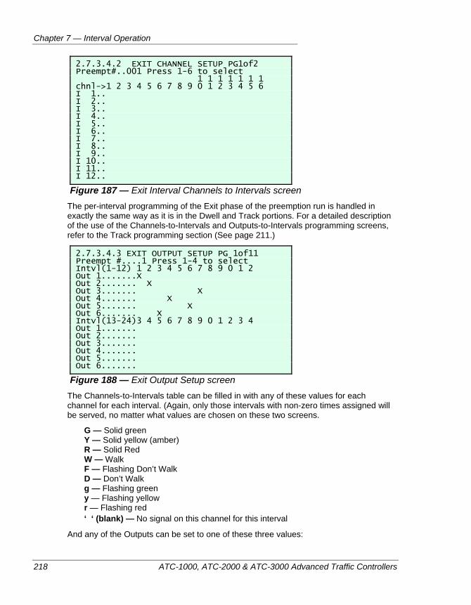
Chapter 7 — Interval Operation
218 ATC-1000, ATC-2000 & ATC-3000 Advanced Traffic Controllers
2.7.3.4.2 EXIT CHANNEL SETUP PG1of2 Preempt#..001 Press 1-6 to select 1 1 1 1 1 1 1 chnl->1 2 3 4 5 6 7 8 9 0 1 2 3 4 5 6 I 1.. I 2.. I 3.. I 4.. I 5.. I 6.. I 7.. I 8.. I 9.. I 10.. I 11.. I 12..
Figure 187 — Exit Interval Channels to Intervals screen The per-interval programming of the Exit phase of the preemption run is handled in exactly the same way as it is in the Dwell and Track portions. For a detailed description of the use of the Channels-to-Intervals and Outputs-to-Intervals programming screens, refer to the Track programming section (See page 211.)
2.7.3.4.3 EXIT OUTPUT SETUP PG 1of11 Preempt #....1 Press 1-4 to select Intvl(1-12) 1 2 3 4 5 6 7 8 9 0 1 2 Out 1.......X Out 2....... X Out 3....... X Out 4....... X Out 5....... X Out 6....... X Intvl(13-24)3 4 5 6 7 8 9 0 1 2 3 4 Out 1....... Out 2....... Out 3....... Out 4....... Out 5....... Out 6.......
Figure 188 — Exit Output Setup screen The Channels-to-Intervals table can be filled in with any of these values for each channel for each interval. (Again, only those intervals with non-zero times assigned will be served, no matter what values are chosen on these two screens.
G — Solid green Y — Solid yellow (amber) R — Solid Red W — Walk F — Flashing Don’t Walk D — Don’t Walk g — Flashing green y — Flashing yellow r — Flashing red ‘ ‘ (blank) — No signal on this channel for this interval
And any of the Outputs can be set to one of these three values:
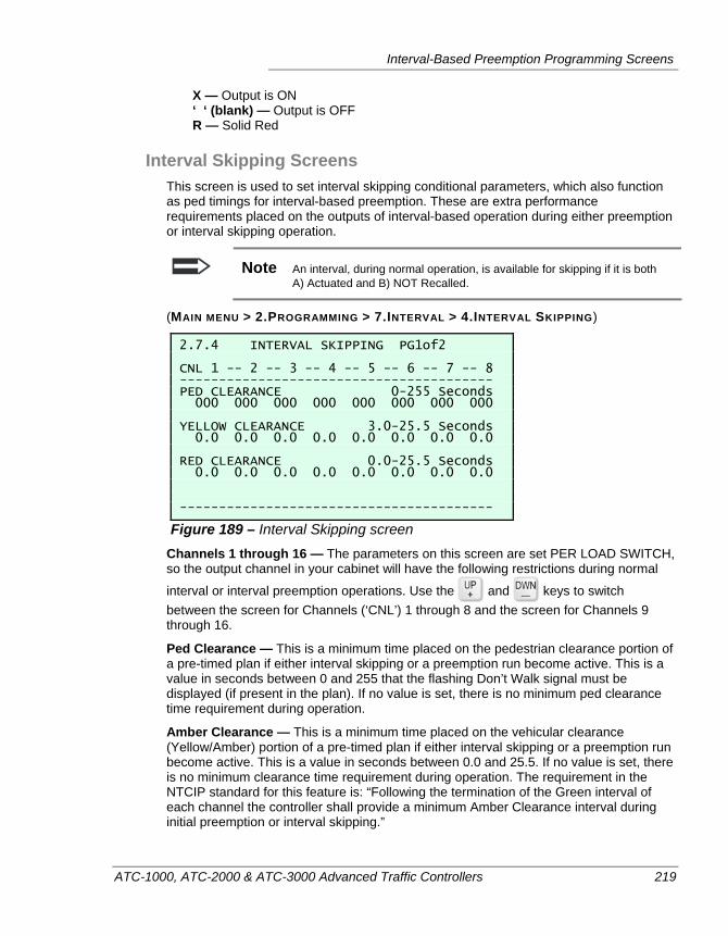
Interval-Based Preemption Programming Screens
ATC-1000, ATC-2000 & ATC-3000 Advanced Traffic Controllers 219
X — Output is ON ‘ ‘ (blank) — Output is OFF R — Solid Red
Interval Skipping Screens This screen is used to set interval skipping conditional parameters, which also function as ped timings for interval-based preemption. These are extra performance requirements placed on the outputs of interval-based operation during either preemption or interval skipping operation.
Note An interval, during normal operation, is available for skipping if it is both A) Actuated and B) NOT Recalled.
(MAIN MENU > 2.PROGRAMMING > 7.INTERVAL > 4.INTERVAL SKIPPING)
2.7.4 INTERVAL SKIPPING PG1of2 CNL 1 -- 2 -- 3 -- 4 -- 5 -- 6 -- 7 -- 8 ---------------------------------------- PED CLEARANCE 0-255 Seconds 000 000 000 000 000 000 000 000 YELLOW CLEARANCE 3.0-25.5 Seconds 0.0 0.0 0.0 0.0 0.0 0.0 0.0 0.0 RED CLEARANCE 0.0-25.5 Seconds 0.0 0.0 0.0 0.0 0.0 0.0 0.0 0.0 ----------------------------------------
Figure 189 – Interval Skipping screen Channels 1 through 16 — The parameters on this screen are set PER LOAD SWITCH, so the output channel in your cabinet will have the following restrictions during normal
interval or interval preemption operations. Use the and keys to switch between the screen for Channels (‘CNL’) 1 through 8 and the screen for Channels 9 through 16.
Ped Clearance — This is a minimum time placed on the pedestrian clearance portion of a pre-timed plan if either interval skipping or a preemption run become active. This is a value in seconds between 0 and 255 that the flashing Don’t Walk signal must be displayed (if present in the plan). If no value is set, there is no minimum ped clearance time requirement during operation.
Amber Clearance — This is a minimum time placed on the vehicular clearance (Yellow/Amber) portion of a pre-timed plan if either interval skipping or a preemption run become active. This is a value in seconds between 0.0 and 25.5. If no value is set, there is no minimum clearance time requirement during operation. The requirement in the NTCIP standard for this feature is: “Following the termination of the Green interval of each channel the controller shall provide a minimum Amber Clearance interval during initial preemption or interval skipping.”
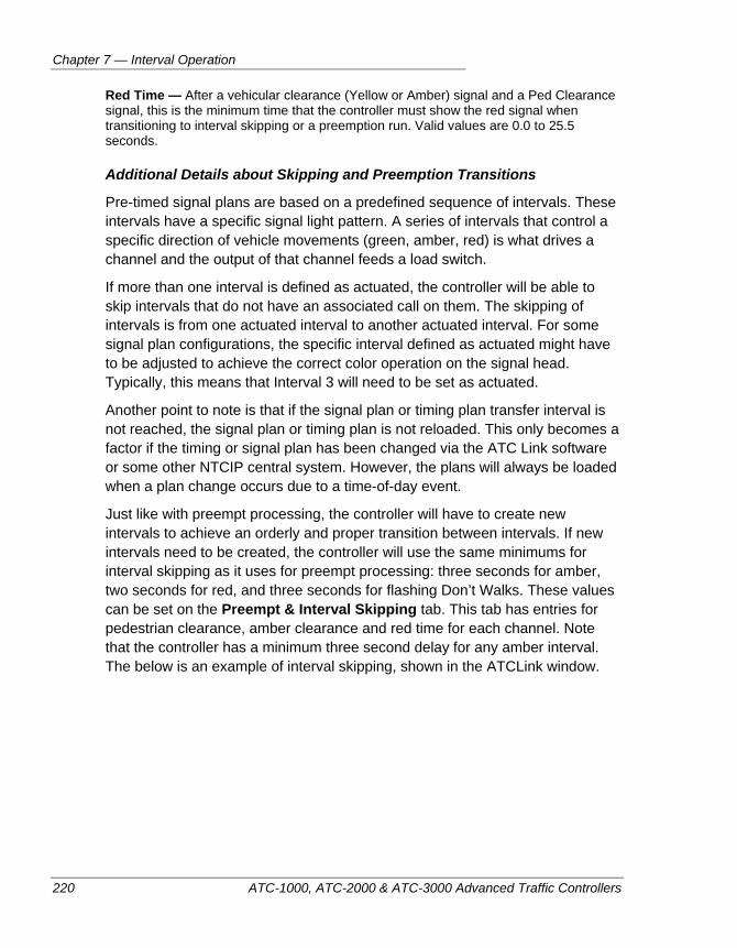
Chapter 7 — Interval Operation
220 ATC-1000, ATC-2000 & ATC-3000 Advanced Traffic Controllers
Red Time — After a vehicular clearance (Yellow or Amber) signal and a Ped Clearance signal, this is the minimum time that the controller must show the red signal when transitioning to interval skipping or a preemption run. Valid values are 0.0 to 25.5 seconds.
Additional Details about Skipping and Preemption Transitions
Pre-timed signal plans are based on a predefined sequence of intervals. These intervals have a specific signal light pattern. A series of intervals that control a specific direction of vehicle movements (green, amber, red) is what drives a channel and the output of that channel feeds a load switch.
If more than one interval is defined as actuated, the controller will be able to skip intervals that do not have an associated call on them. The skipping of intervals is from one actuated interval to another actuated interval. For some signal plan configurations, the specific interval defined as actuated might have to be adjusted to achieve the correct color operation on the signal head. Typically, this means that Interval 3 will need to be set as actuated.
Another point to note is that if the signal plan or timing plan transfer interval is not reached, the signal plan or timing plan is not reloaded. This only becomes a factor if the timing or signal plan has been changed via the ATC Link software or some other NTCIP central system. However, the plans will always be loaded when a plan change occurs due to a time-of-day event.
Just like with preempt processing, the controller will have to create new intervals to achieve an orderly and proper transition between intervals. If new intervals need to be created, the controller will use the same minimums for interval skipping as it uses for preempt processing: three seconds for amber, two seconds for red, and three seconds for flashing Don’t Walks. These values can be set on the Preempt & Interval Skipping tab. This tab has entries for pedestrian clearance, amber clearance and red time for each channel. Note that the controller has a minimum three second delay for any amber interval. The below is an example of interval skipping, shown in the ATCLink window.
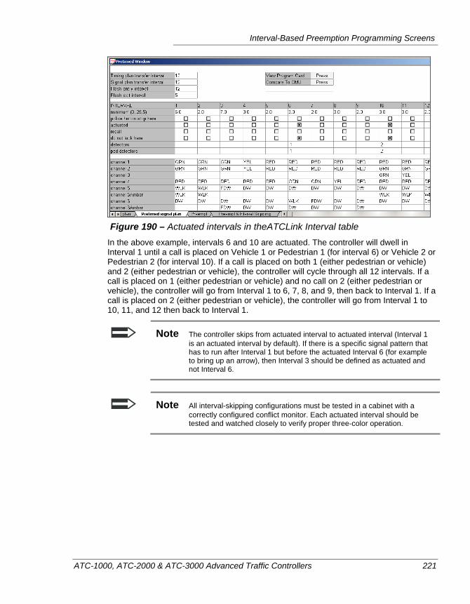
Interval-Based Preemption Programming Screens
ATC-1000, ATC-2000 & ATC-3000 Advanced Traffic Controllers 221
Figure 190 – Actuated intervals in theATCLink Interval table
In the above example, intervals 6 and 10 are actuated. The controller will dwell in Interval 1 until a call is placed on Vehicle 1 or Pedestrian 1 (for interval 6) or Vehicle 2 or Pedestrian 2 (for interval 10). If a call is placed on both 1 (either pedestrian or vehicle) and 2 (either pedestrian or vehicle), the controller will cycle through all 12 intervals. If a call is placed on 1 (either pedestrian or vehicle) and no call on 2 (either pedestrian or vehicle), the controller will go from Interval 1 to 6, 7, 8, and 9, then back to Interval 1. If a call is placed on 2 (either pedestrian or vehicle), the controller will go from Interval 1 to 10, 11, and 12 then back to Interval 1.
Note The controller skips from actuated interval to actuated interval (Interval 1 is an actuated interval by default). If there is a specific signal pattern that has to run after Interval 1 but before the actuated Interval 6 (for example to bring up an arrow), then Interval 3 should be defined as actuated and not Interval 6.
Note All interval-skipping configurations must be tested in a cabinet with a correctly configured conflict monitor. Each actuated interval should be tested and watched closely to verify proper three-color operation.
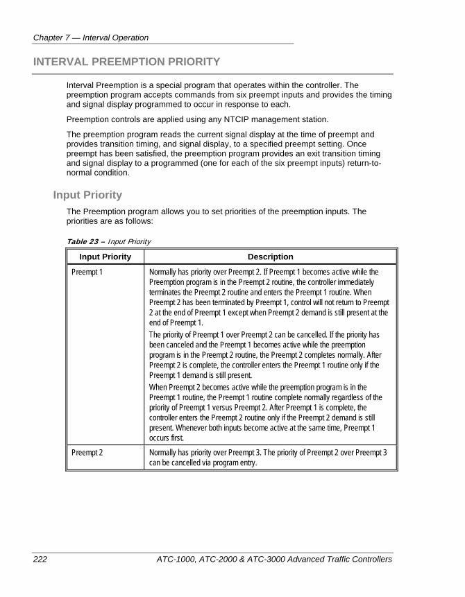
Chapter 7 — Interval Operation
222 ATC-1000, ATC-2000 & ATC-3000 Advanced Traffic Controllers
INTERVAL PREEMPTION PRIORITY
Interval Preemption is a special program that operates within the controller. The preemption program accepts commands from six preempt inputs and provides the timing and signal display programmed to occur in response to each.
Preemption controls are applied using any NTCIP management station.
The preemption program reads the current signal display at the time of preempt and provides transition timing, and signal display, to a specified preempt setting. Once preempt has been satisfied, the preemption program provides an exit transition timing and signal display to a programmed (one for each of the six preempt inputs) return-to-normal condition.
Input Priority The Preemption program allows you to set priorities of the preemption inputs. The priorities are as follows:
Table 23 – Input Priority
Input Priority Description
Preempt 1 Normally has priority over Preempt 2. If Preempt 1 becomes active while the Preemption program is in the Preempt 2 routine, the controller immediately terminates the Preempt 2 routine and enters the Preempt 1 routine. When Preempt 2 has been terminated by Preempt 1, control will not return to Preempt 2 at the end of Preempt 1 except when Preempt 2 demand is still present at the end of Preempt 1. The priority of Preempt 1 over Preempt 2 can be cancelled. If the priority has been canceled and the Preempt 1 becomes active while the preemption program is in the Preempt 2 routine, the Preempt 2 completes normally. After Preempt 2 is complete, the controller enters the Preempt 1 routine only if the Preempt 1 demand is still present. When Preempt 2 becomes active while the preemption program is in the Preempt 1 routine, the Preempt 1 routine complete normally regardless of the priority of Preempt 1 versus Preempt 2. After Preempt 1 is complete, the controller enters the Preempt 2 routine only if the Preempt 2 demand is still present. Whenever both inputs become active at the same time, Preempt 1 occurs first.
Preempt 2 Normally has priority over Preempt 3. The priority of Preempt 2 over Preempt 3 can be cancelled via program entry.
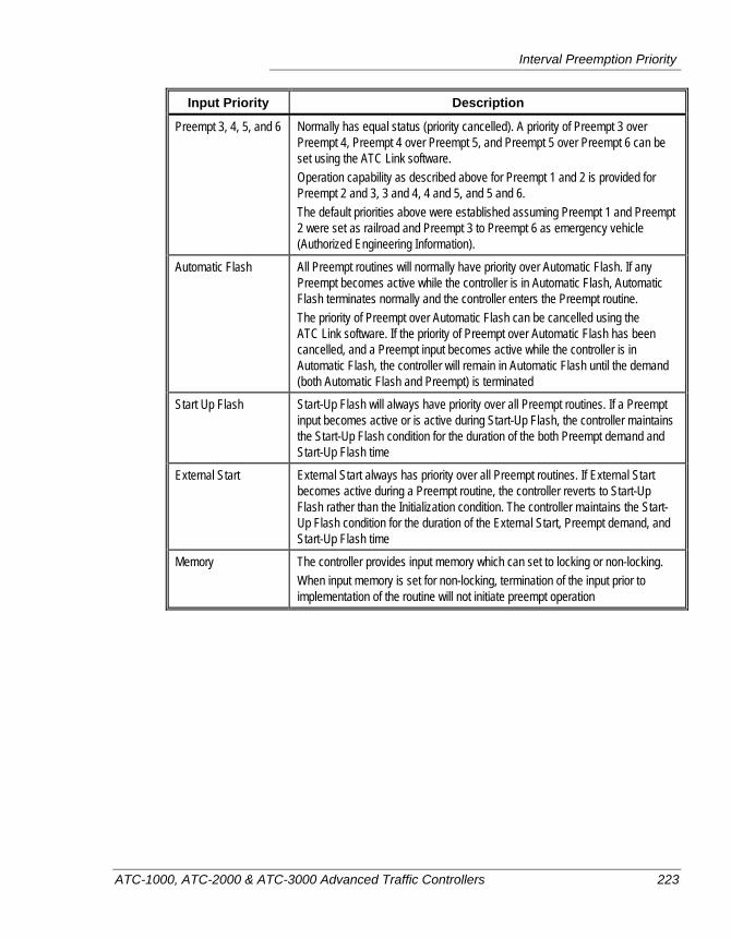
Interval Preemption Priority
ATC-1000, ATC-2000 & ATC-3000 Advanced Traffic Controllers 223
Input Priority Description
Preempt 3, 4, 5, and 6 Normally has equal status (priority cancelled). A priority of Preempt 3 over Preempt 4, Preempt 4 over Preempt 5, and Preempt 5 over Preempt 6 can be set using the ATC Link software. Operation capability as described above for Preempt 1 and 2 is provided for Preempt 2 and 3, 3 and 4, 4 and 5, and 5 and 6. The default priorities above were established assuming Preempt 1 and Preempt 2 were set as railroad and Preempt 3 to Preempt 6 as emergency vehicle (Authorized Engineering Information).
Automatic Flash All Preempt routines will normally have priority over Automatic Flash. If any Preempt becomes active while the controller is in Automatic Flash, Automatic Flash terminates normally and the controller enters the Preempt routine. The priority of Preempt over Automatic Flash can be cancelled using the ATC Link software. If the priority of Preempt over Automatic Flash has been cancelled, and a Preempt input becomes active while the controller is in Automatic Flash, the controller will remain in Automatic Flash until the demand (both Automatic Flash and Preempt) is terminated
Start Up Flash Start-Up Flash will always have priority over all Preempt routines. If a Preempt input becomes active or is active during Start-Up Flash, the controller maintains the Start-Up Flash condition for the duration of the both Preempt demand and Start-Up Flash time
External Start External Start always has priority over all Preempt routines. If External Start becomes active during a Preempt routine, the controller reverts to Start-Up Flash rather than the Initialization condition. The controller maintains the Start-Up Flash condition for the duration of the External Start, Preempt demand, and Start-Up Flash time
Memory The controller provides input memory which can set to locking or non-locking. When input memory is set for non-locking, termination of the input prior to implementation of the routine will not initiate preempt operation
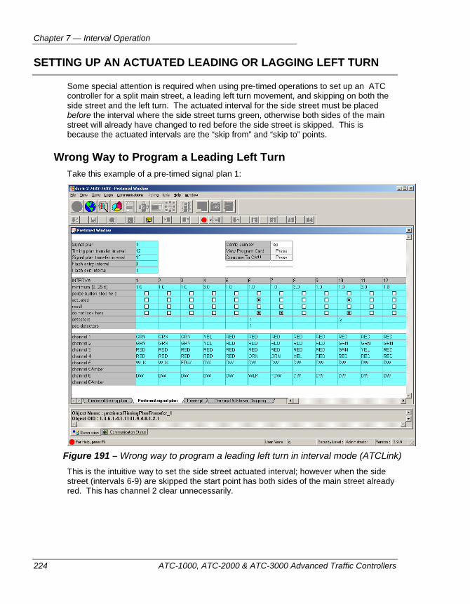
Chapter 7 — Interval Operation
224 ATC-1000, ATC-2000 & ATC-3000 Advanced Traffic Controllers
SETTING UP AN ACTUATED LEADING OR LAGGING LEFT TURN
Some special attention is required when using pre-timed operations to set up an ATC controller for a split main street, a leading left turn movement, and skipping on both the side street and the left turn. The actuated interval for the side street must be placed before the interval where the side street turns green, otherwise both sides of the main street will already have changed to red before the side street is skipped. This is because the actuated intervals are the “skip from” and “skip to” points.
Wrong Way to Program a Leading Left Turn Take this example of a pre-timed signal plan 1:
Figure 191 – Wrong way to program a leading left turn in interval mode (ATCLink) This is the intuitive way to set the side street actuated interval; however when the side street (intervals 6-9) are skipped the start point has both sides of the main street already red. This has channel 2 clear unnecessarily.
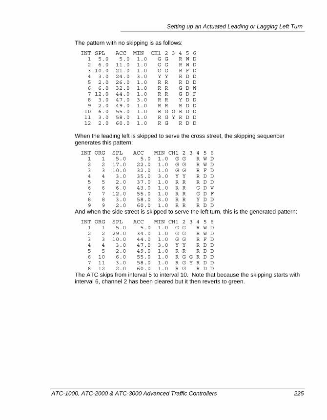
Setting up an Actuated Leading or Lagging Left Turn
ATC-1000, ATC-2000 & ATC-3000 Advanced Traffic Controllers 225
The pattern with no skipping is as follows:
INT SPL ACC MIN CH1 2 3 4 5 6 1 5.0 5.0 1.0 G G R W D 2 6.0 11.0 1.0 G G R W D 3 10.0 21.0 1.0 G G R F D 4 3.0 24.0 3.0 Y Y R D D 5 2.0 26.0 1.0 R R R D D 6 6.0 32.0 1.0 R R G D W 7 12.0 44.0 1.0 R R G D F 8 3.0 47.0 3.0 R R Y D D 9 2.0 49.0 1.0 R R R D D 10 6.0 55.0 1.0 R G G R D D 11 3.0 58.0 1.0 R G Y R D D 12 2.0 60.0 1.0 R G R D D
When the leading left is skipped to serve the cross street, the skipping sequencer generates this pattern:
INT ORG SPL ACC MIN CH1 2 3 4 5 6 1 1 5.0 5.0 1.0 G G R W D 2 2 17.0 22.0 1.0 G G R W D 3 3 10.0 32.0 1.0 G G R F D 4 4 3.0 35.0 3.0 Y Y R D D 5 5 2.0 37.0 1.0 R R R D D 6 6 6.0 43.0 1.0 R R G D W 7 7 12.0 55.0 1.0 R R G D F 8 8 3.0 58.0 3.0 R R Y D D 9 9 2.0 60.0 1.0 R R R D D
And when the side street is skipped to serve the left turn, this is the generated pattern:
INT ORG SPL ACC MIN CH1 2 3 4 5 6 1 1 5.0 5.0 1.0 G G R W D 2 2 29.0 34.0 1.0 G G R W D 3 3 10.0 44.0 1.0 G G R F D 4 4 3.0 47.0 3.0 Y Y R D D 5 5 2.0 49.0 1.0 R R R D D 6 10 6.0 55.0 1.0 R G G R D D 7 11 3.0 58.0 1.0 R G Y R D D 8 12 2.0 60.0 1.0 R G R D D
The ATC skips from interval 5 to interval 10. Note that because the skipping starts with interval 6, channel 2 has been cleared but it then reverts to green.
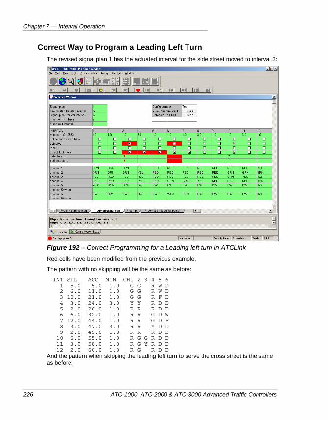
Chapter 7 — Interval Operation
226 ATC-1000, ATC-2000 & ATC-3000 Advanced Traffic Controllers
Correct Way to Program a Leading Left Turn The revised signal plan 1 has the actuated interval for the side street moved to interval 3:
Figure 192 – Correct Programming for a Leading left turn in ATCLink Red cells have been modified from the previous example.
The pattern with no skipping will be the same as before:
INT SPL ACC MIN CH1 2 3 4 5 6 1 5.0 5.0 1.0 G G R W D 2 6.0 11.0 1.0 G G R W D 3 10.0 21.0 1.0 G G R F D 4 3.0 24.0 3.0 Y Y R D D 5 2.0 26.0 1.0 R R R D D 6 6.0 32.0 1.0 R R G D W 7 12.0 44.0 1.0 R R G D F 8 3.0 47.0 3.0 R R Y D D 9 2.0 49.0 1.0 R R R D D 10 6.0 55.0 1.0 R G G R D D 11 3.0 58.0 1.0 R G Y R D D 12 2.0 60.0 1.0 R G R D D
And the pattern when skipping the leading left turn to serve the cross street is the same as before:
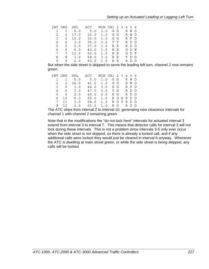
Setting up an Actuated Leading or Lagging Left Turn
ATC-1000, ATC-2000 & ATC-3000 Advanced Traffic Controllers 227
INT ORG SPL ACC MIN CH1 2 3 4 5 6 1 1 5.0 5.0 1.0 G G R W D 2 2 17.0 22.0 1.0 G G R W D 3 3 10.0 32.0 1.0 G G R F D 4 4 3.0 35.0 3.0 Y Y R D D 5 5 2.0 37.0 1.0 R R R D D 6 6 6.0 43.0 1.0 R R G D W 7 7 12.0 55.0 1.0 R R G D F 8 8 3.0 58.0 3.0 R R Y D D 9 9 2.0 60.0 1.0 R R R D D
But when the side street is skipped to serve the leading left turn, channel 2 now remains green:
INT ORG SPL ACC MIN CH1 2 3 4 5 6 1 1 5.0 5.0 1.0 G G R W D 2 2 36.0 41.0 1.0 G G R W D 3 0 3.0 44.0 3.0 G G R F D 4 0 3.0 47.0 3.0 Y G R D D 5 0 2.0 49.0 2.0 R G R D D 6 10 6.0 55.0 1.0 R G G R D D 7 11 3.0 58.0 1.0 R G Y R D D 8 12 2.0 60.0 1.0 R G R D D
The ATC skips from interval 2 to interval 10, generating new clearance intervals for channel 1 with channel 2 remaining green.
Note that in the modifications the “do not lock here” intervals for actuated interval 3 extend from interval 3 to interval 7. This means that detector calls for interval 3 will not lock during these intervals. This is not a problem since intervals 3-5 only ever occur when the side street is not skipped, so there is already a locked call, and if any additional calls were locked they would just be cleared in interval 6 anyway. Whenever the ATC is dwelling at main street green, or while the side street is being skipped, any calls will be locked.
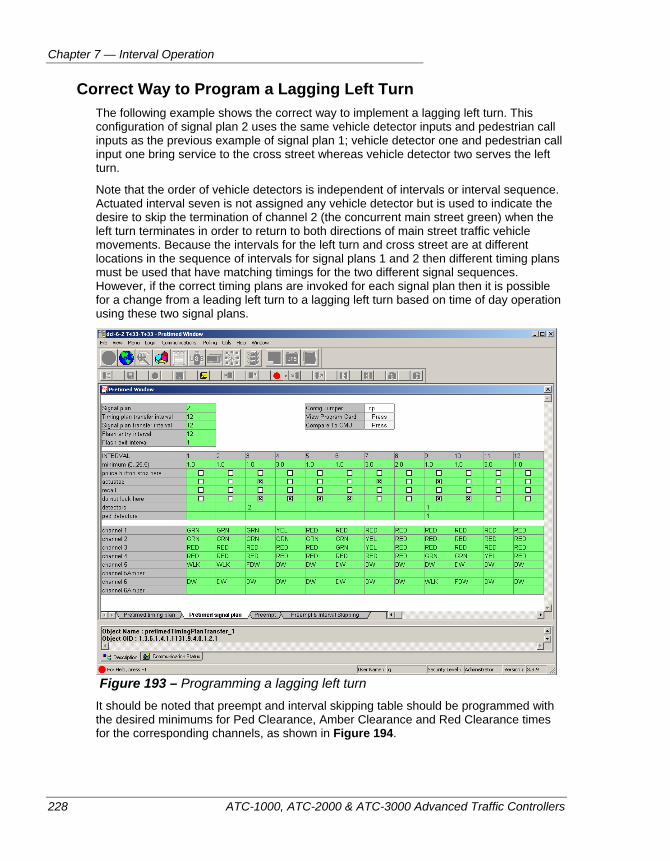
Chapter 7 — Interval Operation
228 ATC-1000, ATC-2000 & ATC-3000 Advanced Traffic Controllers
Correct Way to Program a Lagging Left Turn The following example shows the correct way to implement a lagging left turn. This configuration of signal plan 2 uses the same vehicle detector inputs and pedestrian call inputs as the previous example of signal plan 1; vehicle detector one and pedestrian call input one bring service to the cross street whereas vehicle detector two serves the left turn.
Note that the order of vehicle detectors is independent of intervals or interval sequence. Actuated interval seven is not assigned any vehicle detector but is used to indicate the desire to skip the termination of channel 2 (the concurrent main street green) when the left turn terminates in order to return to both directions of main street traffic vehicle movements. Because the intervals for the left turn and cross street are at different locations in the sequence of intervals for signal plans 1 and 2 then different timing plans must be used that have matching timings for the two different signal sequences. However, if the correct timing plans are invoked for each signal plan then it is possible for a change from a leading left turn to a lagging left turn based on time of day operation using these two signal plans.
Figure 193 – Programming a lagging left turn
It should be noted that preempt and interval skipping table should be programmed with the desired minimums for Ped Clearance, Amber Clearance and Red Clearance times for the corresponding channels, as shown in Figure 194.
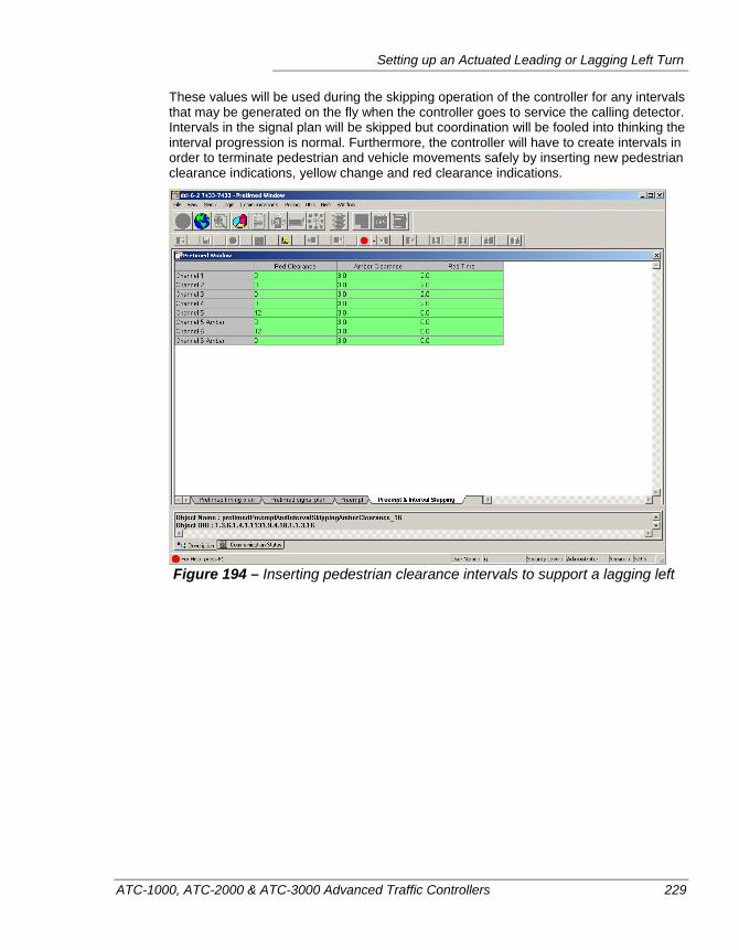
Setting up an Actuated Leading or Lagging Left Turn
ATC-1000, ATC-2000 & ATC-3000 Advanced Traffic Controllers 229
These values will be used during the skipping operation of the controller for any intervals that may be generated on the fly when the controller goes to service the calling detector. Intervals in the signal plan will be skipped but coordination will be fooled into thinking the interval progression is normal. Furthermore, the controller will have to create intervals in order to terminate pedestrian and vehicle movements safely by inserting new pedestrian clearance indications, yellow change and red clearance indications.
Figure 194 – Inserting pedestrian clearance intervals to support a lagging left

Chapter 7 — Interval Operation
230 ATC-1000, ATC-2000 & ATC-3000 Advanced Traffic Controllers
ATC-1000, ATC-2000 & ATC-3000 Advanced Traffic Controllers 231
Chapter 8 — Phase-based Preemption
This chapter describes how to set up phase-based preemption in the ATC-1000 controller, including configuring a set of preemption intervals and configuring how preemption is triggered. Interval-based preemption is not discussed here, but rather in the previous chapter. The following topics are discussed in detail in this chapter:
• Overview of Preemption, on page 232
• Phases of a Preemption Run, on page 232
• Control and Timing parameters, on page 235
• Preemption Linking, on page 233
• Phase Pedestrian and Overlap parameters, on page 239
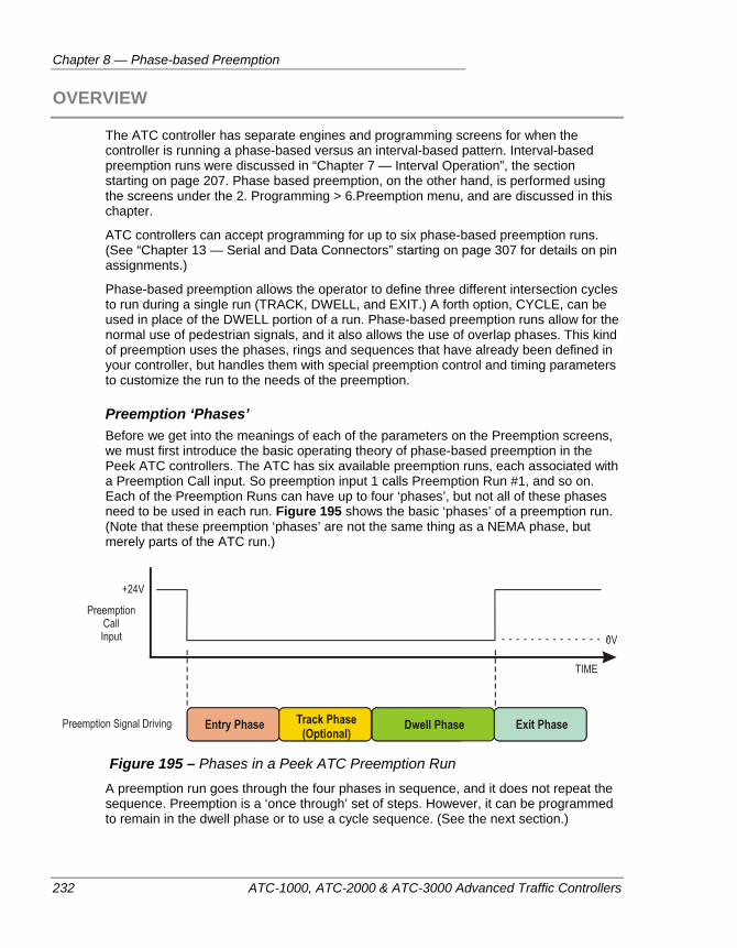
Chapter 8 — Phase-based Preemption
232 ATC-1000, ATC-2000 & ATC-3000 Advanced Traffic Controllers
OVERVIEW
The ATC controller has separate engines and programming screens for when the controller is running a phase-based versus an interval-based pattern. Interval-based preemption runs were discussed in “Chapter 7 — Interval Operation”, the section starting on page 207. Phase based preemption, on the other hand, is performed using the screens under the 2. Programming > 6.Preemption menu, and are discussed in this chapter.
ATC controllers can accept programming for up to six phase-based preemption runs. (See “Chapter 13 — Serial and Data Connectors” starting on page 307 for details on pin assignments.)
Phase-based preemption allows the operator to define three different intersection cycles to run during a single run (TRACK, DWELL, and EXIT.) A forth option, CYCLE, can be used in place of the DWELL portion of a run. Phase-based preemption runs allow for the normal use of pedestrian signals, and it also allows the use of overlap phases. This kind of preemption uses the phases, rings and sequences that have already been defined in your controller, but handles them with special preemption control and timing parameters to customize the run to the needs of the preemption.
Preemption ‘Phases’ Before we get into the meanings of each of the parameters on the Preemption screens, we must first introduce the basic operating theory of phase-based preemption in the Peek ATC controllers. The ATC has six available preemption runs, each associated with a Preemption Call input. So preemption input 1 calls Preemption Run #1, and so on. Each of the Preemption Runs can have up to four ‘phases’, but not all of these phases need to be used in each run. Figure 195 shows the basic ‘phases’ of a preemption run. (Note that these preemption ‘phases’ are not the same thing as a NEMA phase, but merely parts of the ATC run.)
Figure 195 – Phases in a Peek ATC Preemption Run
A preemption run goes through the four phases in sequence, and it does not repeat the sequence. Preemption is a ‘once through’ set of steps. However, it can be programmed to remain in the dwell phase or to use a cycle sequence. (See the next section.)
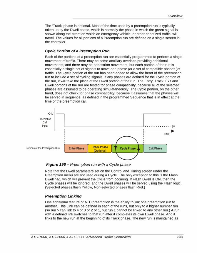
Overview
ATC-1000, ATC-2000 & ATC-3000 Advanced Traffic Controllers 233
The ‘Track’ phase is optional. Most of the time used by a preemption run is typically taken up by the Dwell phase, which is normally the phase in which the green signal is shown along the street on which an emergency vehicle, or other prioritized traffic, will travel. The values for all portions of a Preemption run are defined on a single screen in the controller.
Cycle Portion of a Preemption Run Each of the portions of a preemption run are essentially programmed to perform a single movement of traffic. There may be some ancillary overlaps providing additional movements, and there may be pedestrian movement, but each portion of the run is essentially a single set of signals to move one phase (or a set of compatible phases )of traffic. The Cycle portion of the run has been added to allow the heart of the preemption run to include a set of cycling signals. If any phases are defined for the Cycle portion of the run, it will take the place of the Dwell portion of the run. The Entry, Track, Exit and Dwell portions of the run are tested for phase compatibility, because all of the selected phases are assumed to be operating simulataneously. The Cycle portion, on the other hand, does not check for phase compatibility, because it assumes that the phases will be served in sequence, as defined in the programmed Sequence that is in effect at the time of the preemption call.
Figure 196 – Preemption run with a Cycle phase
Note that the Dwell parameters set on the Control and Timing screen under the Preemption menu are not used during a Cycle. The only exception to this is the Flash Dwell flag, which will prevent the Cycle from occuring. If Flash Dwell is ON, then the Cycle phases will be ignored, and the Dwell phases will be served using the Flash logic. (Selected phases flash Yellow, Non-selected phases flash Red.)
Preemption Linking One additional feature of ATC preemption is the ability to link one preemption run to another. This Link can be defined in each of the runs, but only to a higher number run (so run 5 can link to 4 or 3 or 2 or 1, but run 1 cannot be linked to any other run.) A run with a defined link switches to that run after it completes its own Dwell phase. And it links to the new run at the beginning of its Track phase. The new run is maintained as
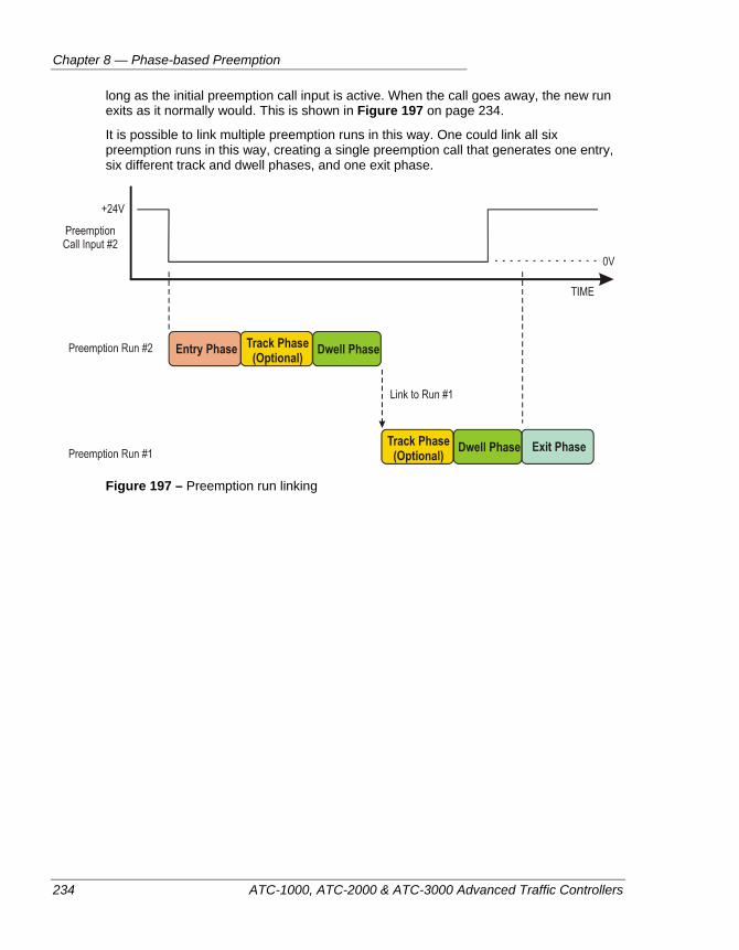
Chapter 8 — Phase-based Preemption
234 ATC-1000, ATC-2000 & ATC-3000 Advanced Traffic Controllers
long as the initial preemption call input is active. When the call goes away, the new run exits as it normally would. This is shown in Figure 197 on page 234.
It is possible to link multiple preemption runs in this way. One could link all six preemption runs in this way, creating a single preemption call that generates one entry, six different track and dwell phases, and one exit phase.
Figure 197 – Preemption run linking
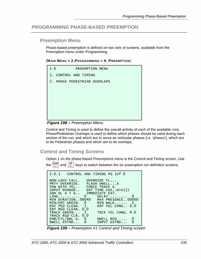
Programming Phase-Based Preemption
ATC-1000, ATC-2000 & ATC-3000 Advanced Traffic Controllers 235
PROGRAMMING PHASE-BASED PREEMPTION
Preemption Menu Phase-based preemption is defined on two sets of screens, available from the Preemption menu under Programming.
(MAIN MENU > 2.PROGRAMMING > 6. PREEMPTION)
2.6 PREEMPTION MENU 1. CONTROL AND TIMING 2. PHASE PEDESTRIAN OVERLAPS
Figure 198 – Preemption Menu Control and Timing is used to define the overall activity of each of the available runs. Phase/Pedestrian Overlaps is used to define which phases should be used during each section of the run, and which are to serve as vehicular phases (i.e. ‘phases’), which are to be Pedestrian phases and which are to be overlaps.
Control and Timing Screens Option 1 on the phase-based Preemptions menu is the Control and Timing screen. Use
the and keys to switch between the six preemption run definition screens.
2.6.1 CONTROL AND TIMING PG 1of 6 NON-LOCK CALL. OVERRIDE FL... PRTY OVERRIDE. FLASH DWELL...X FDW WITH YEL.. FORCE TRACK G. INPUT MIRROR.. ENT TIME USE..min(1) INH OL A T G.. IMMEDIATE EXT. LINK.......... 0 DELAY......... 0 MIN DURATION..00040 MAX PRESENCE..00060 MIN/ENT GREEN. 0 MIN WALK...... 1 ENT PED CLEAR. 1 ENT YEL CHNG.. 0.0 ENT RED CLEAR. 0.0 TRACK GREEN... 5 TRCK YEL CHNG. 0.0 TRACK RED CLR. 0.0 ENB/CYL/DWL G. 0 DWELL RED..... 0 DWELL EXTND... 0 INPUT EXTND... 0
Figure 199 – Preemption #1 Control and Timing screen
Chapter 8 — Phase-based Preemption
236 ATC-1000, ATC-2000 & ATC-3000 Advanced Traffic Controllers
Control and Timing Parameters Here are the details about the various preemption parameters:
Non-Lock Call — This toggles on (‘X’) or off (‘ ‘) to indicate whether this preemption run has a non-locking input call. This means that if Non-Lock Call has an ‘X’, and if a call is placed on this Preemption input, but the call goes away before the Delay timer has completed (see ‘Delay’, below), the call will be discarded and no preemption run will result.
Override FL — Do not allow preemption to override flash. If this option is checked ‘X’, a preemption call will not override automatic flash mode.
PRTY Override — Normally, preemption calls are able to interrupt one another with no priority, the Priority Override command, however, tells this preemption run that the priority order of the preemption numbers will apply to this run. If this option is checked, the number order of the call is important, Preemption run 1 is a higher priority than 2 and so on. So, if the controller is running Preemption Run #3, and a Preemption #2 call comes in, and the PRTY Override for run #3 is set to ‘X’, then Preemption #2 will interrupt Run 3 and begin operating. If PRTY Override was set to ‘ ‘, Run #3 would continue and the controller would ignore the Preemption #2 call.
Flash Dwell — This is an option that tells the preemption run how to handle phases that are marked as a ‘DWELL Ph’. When this option is checked ‘X’, dwell phases in the run flash Yellow during the dwell period. Phases not selected as dwell phases will flash Red. Note that this flag is the only control that will override the programming of a Cycle portion to the preemption run. Normally, Cycle will take the place of the Dwell portion if any Cycle phases are selected. However, Flash Dwell will override this; the Cycle portion will be ignored and the selected Dwell phases will flash Yellow and unselected Dwell phases will flash Red, until the preemption input goes away.
FDW with YEL — When checked, this causes a flashing ‘Don’t Walk’ signal through the yellow signal during entry into the preemption run.
Force Track G — Force a reservice of the track phase while the preemption input is still active. Prevents the run from moving to the Exit portion of the run. If the preempt call is removed and comes back, then do not serve the exit phase and go directly to the track phase.
Input Mirror — This is a feature that is used to check for cabinet wiring errors in connecting preemption inputs. The controller will test a preemption input and one other input to verify that they are opposite in state from one another. For example, if Preemption input #3 is low, the input mirror input should be high. If Preempt#3 goes high, then the mirror must switch low. The channel to watch for this preemption input mirror must be defined in the cabinet I/O Map by assigning the Function ‘Preempt Mirror’ to an input pin. (Refer to “I/O Mapping” on page 101.) This Preempt Mirror function can only be applied to one physical input in the I/O map.
ENT Time Use — Preemption Entry Time Mode to use. This setting applies to every interval in the run. If set to min(1), the run uses the smaller value compared between the preemption entry time and the phase time. If set to max(2), the run uses the larger value compared between the preemption entry time and the phase time. Finally, if set to preempt(3), the run always uses the preemption entry time value.
Programming Phase-Based Preemption
ATC-1000, ATC-2000 & ATC-3000 Advanced Traffic Controllers 237
INH OL A T G — Inhibit Overlaps After Track Clearance. This parameter will cause the termination of any overlaps that are currently timing after the track green interval. For example, if the Track Clearance phase includes a trailling overlap with Green/Yellow/Red times assigned, this setting will force the overlap to terminate with the parent phase.
Immediate Ext — This switch tells the run to immediately exit for a higher priority preemption call. When this parameter is set and a higher priority (higher number) preemption input becomes active, it causes the current preemption run to terminate. The Exit phases of the current run get replaced with the track clearance or Dwell phases of the new run. If the current run is in Dwell, and the minimum dwell time hasn’t been met yet, the run waits for this limit before terminating. If the Dwell flash is active, a normal exit from flash to stop/go operation is enforced before the termination. When this parameter is NOT set, the normal term of the preemption run, including its Exit phases, are used to allow a graceful transition back to normal operation before servicing the higher priority run.
Link — This is a way to link the operation of one preemption run to another, but it only works if you are linking to a higher priority run (i.e. Run #2 links to Run#1 is valid, but Run#1 cannot link to any other run) The link is activated at the end of the Dwell phase of the current run, and jumps to the beginning of the Track phase of the linked run. The rest of the new run is performed as defined, however it’s input is controlled by the original run’s preemption call input.
Delay — This is a delay time, in seconds, that the controller will wait after the preemption input goes active before the controller will begin executing the Entry phase of the run. Note that if the input goes OFF before the delay time is over, and the Non-Lock Call option is selected above, the run will not start.
Min Duration — This is the minimum length of time, in seconds, that the full preemption is allowed to run. This timer begins at the end of any Delay time you’ve placed on the run input, and it will prevent the Dwell phase from ending until this time has elapsed.
Max Presence — This is the time in seconds that the controller will consider a preemption input valid. If the preemption detector is faulty, or if a vehicle parks within sight-line of the preemption receiver and keeps the intersection input high the whole time, this timer functions as a ‘time out’ for the preemption input.
Min/Ent Green — Also known as the Preempt Minimum Green Time, this is the minimum amount of time, in seconds, that any of the preemption phases can be allowed to show a green signal. This is to prevent a Dwell or other phase from being truncated in an unsafe manner should the preemption input suddenly go away. This minimum time also applies to the normal operation greens that are active when the Preemption run is first activated. In the case of entry phase greens, the controller will compare this value with the green phase’s own Min Green time and use the lesser value.
Min Walk — This is similar to the Min Green function for preemption, only it prevents any Pedestrian Walk phase during the preemption run from being cut off by the sudden removal of the preemption input signal. This is the minimum time, in seconds, that should be allowed for preemption run Walk signals. This minimum walk time also applies to the normal operation pedestrians phases that are being serviced when the Preemption run is first activated.
Chapter 8 — Phase-based Preemption
238 ATC-1000, ATC-2000 & ATC-3000 Advanced Traffic Controllers
Ent Ped Clear — This is the amount of clearance time that is allotted to a pedestrian phase that is interrupted by the preemption run. The actual amount of time that is used for pedestrian clearance is either this time, or the time stored in the normal pedestrian phase, whichever is the lower value.
Ent Yel Chng — Entry Yellow Change time, in tenths of a second. The value can be anything from 0.0 to 25.5 seconds. This limits the change of timing for a normal Yellow that is terminated by a preemption initiated transition. The value will be compared to the phase’s Yellow Change time, and the lesser value will be used. CAUTION: If this value is set to 0.0, the phase’s yellow will be terminated immediately.
Ent Red Clear — Entry Red Change time, in tenths of a second. The value can be anything from 0.0 to 25.5 seconds. This controls the timing of a red signal that is interrupted by a preemption call. The red will not be terminated before the lesser of this value or the phase’s own Red Clearance timer. CAUTION: If this value is set to 0.0., the phase’s red will be terminated immediately.
Track Green — The amount of time, in seconds, that is allotted to the Track phases portion of this pedestrian run. The default value is zero.
Track YEL Change — Track clearance yellow change time in tenths of seconds (0.0 to 25.5 seconds.) The lesser value between this parameter and the yellow change time of the phases designated as Track phases controls the yellow timing for the track clearance movement. Track phases are enabled by placing a check in the Track Ph row on the Phase/Pedestrian/Overlaps screen of the Preemption menu. (MM > 2 > 6 > 2)
Track Red Clear — The Track Red Clear time, in tenths of seconds. Valid values can be in the range 0.0 to 25.5 seconds. The lesser value of this parameter or the phase’s own red clearance timing value (of whichever phase or phases have been assigned to be Track phases during this preemption run) will be used. Track phases are enabled by placing an ‘X’ in the Track Ph row on the Phase/Pedestrian/Overlaps screen of the Preemption menu. (MM > 2 > 6 > 2)
ENB/CYL/DWL G — Important: if a value is programmed here, it enables the preemption run. If no value is programmed here then the preempt run is disabled. This parameter controls the minimum timing for the Dwell portion of the Preemption run. This is a value in seconds in the range from 1 to 255 seconds. The phase or phases that have been enabled for this preemption run will not terminate before all of these condistions have been met:
A) the completion of the Preemptioin Duration Timer (MIN DURATION on this screen),
B) The completion of this preemption Dwell timer (ENB/C”YL/DWL G), and
C) the preemption call input is no longer active
Dwell Red — When this parameter is set to a non-zero value, and there are no Track phases programmed for this preemption run, will automatically terminate any main street phases that are programmed as Dwell phases. This is done to prevent the ‘left turn trap’ scenario. Please note that if this value is non-zero and the dwell phases are programmed as phases 2 and 6, and a red interval is programmed, and there are no track phases programmed, the controller will terminate phases 2 and 6, rest in Red for the programmed time, and then bring phases 2 and 6 back on.
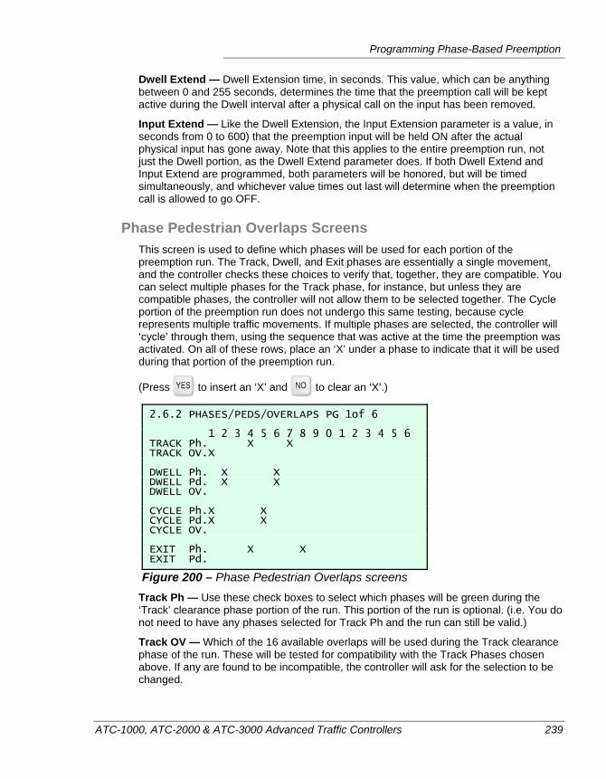
Programming Phase-Based Preemption
ATC-1000, ATC-2000 & ATC-3000 Advanced Traffic Controllers 239
Dwell Extend — Dwell Extension time, in seconds. This value, which can be anything between 0 and 255 seconds, determines the time that the preemption call will be kept active during the Dwell interval after a physical call on the input has been removed.
Input Extend — Like the Dwell Extension, the Input Extension parameter is a value, in seconds from 0 to 600) that the preemption input will be held ON after the actual physical input has gone away. Note that this applies to the entire preemption run, not just the Dwell portion, as the Dwell Extend parameter does. If both Dwell Extend and Input Extend are programmed, both parameters will be honored, but will be timed simultaneously, and whichever value times out last will determine when the preemption call is allowed to go OFF.
Phase Pedestrian Overlaps Screens This screen is used to define which phases will be used for each portion of the preemption run. The Track, Dwell, and Exit phases are essentially a single movement, and the controller checks these choices to verify that, together, they are compatible. You can select multiple phases for the Track phase, for instance, but unless they are compatible phases, the controller will not allow them to be selected together. The Cycle portion of the preemption run does not undergo this same testing, because cycle represents multiple traffic movements. If multiple phases are selected, the controller will ‘cycle’ through them, using the sequence that was active at the time the preemption was activated. On all of these rows, place an ‘X’ under a phase to indicate that it will be used during that portion of the preemption run.
(Press to insert an ‘X’ and to clear an ‘X’.)
2.6.2 PHASES/PEDS/OVERLAPS PG 1of 6 1 2 3 4 5 6 7 8 9 0 1 2 3 4 5 6 TRACK Ph. X X TRACK OV.X DWELL Ph. X X DWELL Pd. X X DWELL OV. CYCLE Ph.X X CYCLE Pd.X X CYCLE OV. EXIT Ph. X X EXIT Pd.
Figure 200 – Phase Pedestrian Overlaps screens Track Ph — Use these check boxes to select which phases will be green during the ‘Track’ clearance phase portion of the run. This portion of the run is optional. (i.e. You do not need to have any phases selected for Track Ph and the run can still be valid.)
Track OV — Which of the 16 available overlaps will be used during the Track clearance phase of the run. These will be tested for compatibility with the Track Phases chosen above. If any are found to be incompatible, the controller will ask for the selection to be changed.
Chapter 8 — Phase-based Preemption
240 ATC-1000, ATC-2000 & ATC-3000 Advanced Traffic Controllers
Dwell Ph — Use the Yes and No buttons to select which of the intersection phases will be Green during the Dwell portion of the preemption run. An ‘X’ indicates that this phase will be a Dwell phase during the run. At least one Dwell phase is required in order for the controller to judge this is a valid preemption run. If the Flash Dwell option is checked, above, then these phases will be displayed as flashing yellow rather than green. The phases selected here will be tested for compatibility with one another. Also, the Dwell phases will be ignored if any phases are programmed as Cycle phases, as the Cycle will take precedence. (Unless ‘Flash Dwell’ is selected.)
Dwell Pd — Use this array to select which of the intersection phases will be pedestrian Walk phases during the Dwell portion of the preemption run. During preemption, pedestrian phases don’t automatically run with their parent vehicular phases. That is why these selections are available for the Dwell, Cycle, and Exit portions of the preemption run programming.
Dwell OV — Select which overlaps will be used during the Dwell portion of the preemption run. These overlaps will be tested for compatibility with the selected Dwell Phases.
Cycle Ph — Unlike the other portions of the run, the Cycle portion may serve multiple movements of vehicles during the run. When programmed, the Cycle portion will take the place of the Dwell portion of the run, and it will serve a selection of phases in sequence, as defined by the phase sequence programming that was in effect when the preemption run was called. The only exception to this is if the Dwell portion is programmed with the ‘Flash Dwell’ flag set, in which case the Dwell portion will be served, with all selected phases flashing yellow, and all non-selected phases flashing Red.
Cycle Pd — Selects which pedestrian phases will be served during the Cycle portion of the preemption run. If more than one are selected, the phases will be served based on the programmed Sequence of the Vehicular parent phases.
Cycle OV — Used to select which overlaps will be served during the Cycle portion of the preemption run. These will be served using the overlaps’ defined parent/modifier phase programming.
Exit Ph — Use this array of checkboxes to select which of the intersection phases will be green during the Exit portion of the preemption run.
Exit Pd — Select which pedestrian phases will be served during the Exit portion of the preemption run.
Note Only phases that have been enabled and programmed as part o f the intersection sequence are available for selection on this screen. If one attempts to place a disabled or unprogrammed phase into a section of the preemption run, you will see a message something like this:
DATABASE UPDATE FAILED, PE TRACK PHASE DISABLE FAULT
ATC-1000, ATC-2000 & ATC-3000 Advanced Traffic Controllers 241
Chapter 9 — Overlaps
This section explains phase-based Overlaps, or conditiional phases that can run at the same time as other phases. The following topics are discussed in detail in this chapter:
• A discussion of the basic theory of overlap operation, on page 242.
• Vehicular overlaps, starting on page 249.
• Pedestrian phase overlaps, starting on page 254.
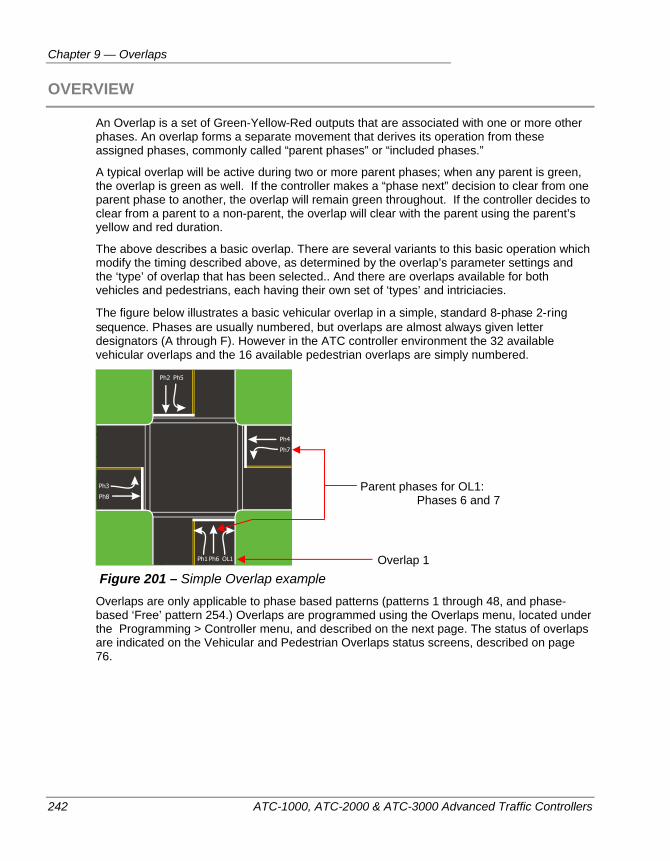
Chapter 9 — Overlaps
242 ATC-1000, ATC-2000 & ATC-3000 Advanced Traffic Controllers
OVERVIEW
An Overlap is a set of Green-Yellow-Red outputs that are associated with one or more other phases. An overlap forms a separate movement that derives its operation from these assigned phases, commonly called “parent phases” or “included phases.”
A typical overlap will be active during two or more parent phases; when any parent is green, the overlap is green as well. If the controller makes a “phase next” decision to clear from one parent phase to another, the overlap will remain green throughout. If the controller decides to clear from a parent to a non-parent, the overlap will clear with the parent using the parent’s yellow and red duration.
The above describes a basic overlap. There are several variants to this basic operation which modify the timing described above, as determined by the overlap’s parameter settings and the ‘type’ of overlap that has been selected.. And there are overlaps available for both vehicles and pedestrians, each having their own set of ‘types’ and intriciacies.
The figure below illustrates a basic vehicular overlap in a simple, standard 8-phase 2-ring sequence. Phases are usually numbered, but overlaps are almost always given letter designators (A through F). However in the ATC controller environment the 32 available vehicular overlaps and the 16 available pedestrian overlaps are simply numbered.
Figure 201 – Simple Overlap example
Overlaps are only applicable to phase based patterns (patterns 1 through 48, and phase-based ‘Free’ pattern 254.) Overlaps are programmed using the Overlaps menu, located under the Programming > Controller menu, and described on the next page. The status of overlaps are indicated on the Vehicular and Pedestrian Overlaps status screens, described on page 76.
Parent phases for OL1: Phases 6 and 7
Overlap 1
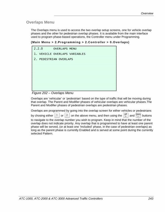
Overview
ATC-1000, ATC-2000 & ATC-3000 Advanced Traffic Controllers 243
Overlaps Menu
The Overlaps menu is used to access the two overlap setup screens, one for vehicle overlap phases and the other for pedestrian overlap phases. It is available from the main interface used to program phase-based operations, the Controller menu under Programming.
(Main Menu > 2.Programming > 2.Control ler > 0.Overlaps)
2.2.0 OVERLAPS MENU 1. VEHICLE OVERLAPS VARIABLES 2. PEDESTRIAN OVERLAPS
Figure 202 – Overlaps Menu Overlaps are ‘vehicular’ or ‘pedestrian’ based on the type of traffic that will be moving during that overlap. The Parent and Modifier phases of vehicular overlaps are vehicular phases.The Parent and Modifier phases of pedestrian overlaps are pedestrian phases.
Overlaps are programmed by going into the overlap screen for either vehicles or pedestrians
by chosing either or on the above menu, and then using the and buttons to navigate to the overlap number you wish to program. Keep in mind that the number of the overlap does not indicate priority. Any overlap that is programmed to have at least one parent phase will be served, (or at least one ‘Included’ phase, in the case of pedestrian overlaps) as long as the parent phase is currently Enabled and is served at some point during the currently selected Pattern.
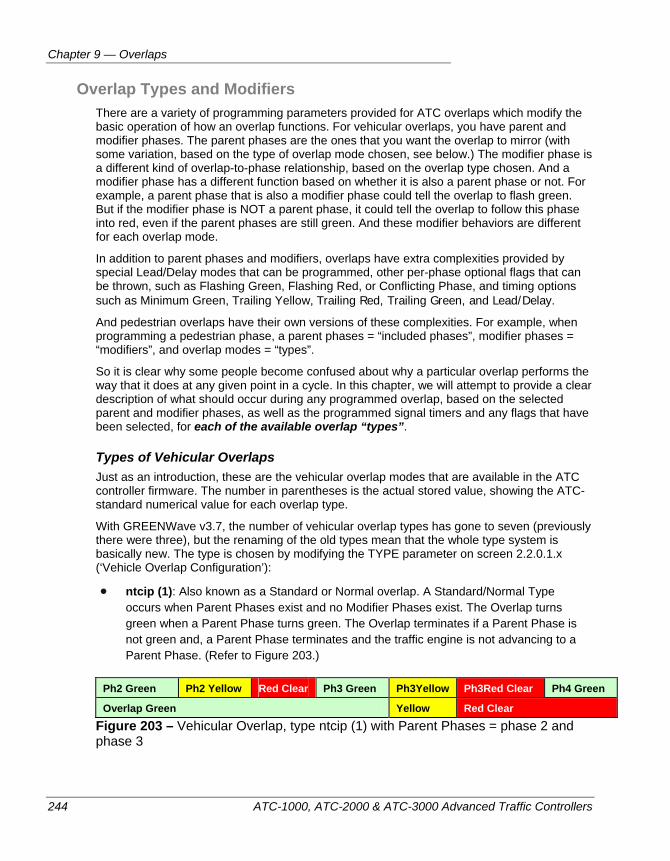
Chapter 9 — Overlaps
244 ATC-1000, ATC-2000 & ATC-3000 Advanced Traffic Controllers
Overlap Types and Modifiers There are a variety of programming parameters provided for ATC overlaps which modify the basic operation of how an overlap functions. For vehicular overlaps, you have parent and modifier phases. The parent phases are the ones that you want the overlap to mirror (with some variation, based on the type of overlap mode chosen, see below.) The modifier phase is a different kind of overlap-to-phase relationship, based on the overlap type chosen. And a modifier phase has a different function based on whether it is also a parent phase or not. For example, a parent phase that is also a modifier phase could tell the overlap to flash green. But if the modifier phase is NOT a parent phase, it could tell the overlap to follow this phase into red, even if the parent phases are still green. And these modifier behaviors are different for each overlap mode.
In addition to parent phases and modifiers, overlaps have extra complexities provided by special Lead/Delay modes that can be programmed, other per-phase optional flags that can be thrown, such as Flashing Green, Flashing Red, or Conflicting Phase, and timing options such as Minimum Green, Trailing Yellow, Trailing Red, Trailing Green, and Lead/Delay.
And pedestrian overlaps have their own versions of these complexities. For example, when programming a pedestrian phase, a parent phases = “included phases”, modifier phases = “modifiers”, and overlap modes = “types”.
So it is clear why some people become confused about why a particular overlap performs the way that it does at any given point in a cycle. In this chapter, we will attempt to provide a clear description of what should occur during any programmed overlap, based on the selected parent and modifier phases, as well as the programmed signal timers and any flags that have been selected, for each of the available overlap “types”.
Types of Vehicular Overlaps Just as an introduction, these are the vehicular overlap modes that are available in the ATC controller firmware. The number in parentheses is the actual stored value, showing the ATC-standard numerical value for each overlap type.
With GREENWave v3.7, the number of vehicular overlap types has gone to seven (previously there were three), but the renaming of the old types mean that the whole type system is basically new. The type is chosen by modifying the TYPE parameter on screen 2.2.0.1.x (‘Vehicle Overlap Configuration’):
ntcip (1): Also known as a Standard or Normal overlap. A Standard/Normal Type occurs when Parent Phases exist and no Modifier Phases exist. The Overlap turns green when a Parent Phase turns green. The Overlap terminates if a Parent Phase is not green and, a Parent Phase terminates and the traffic engine is not advancing to a Parent Phase. (Refer to Figure 203.)
Ph2 Green Ph2 Yellow Red Clear Ph3 Green Ph3Yellow Ph3Red Clear Ph4 Green
Overlap Green Yellow Red Clear Figure 203 – Vehicular Overlap, type ntcip (1) with Parent Phases = phase 2 and phase 3
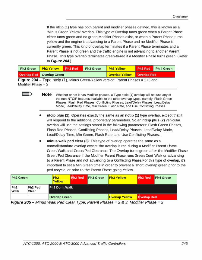
Overview
ATC-1000, ATC-2000 & ATC-3000 Advanced Traffic Controllers 245
If the ntcip (1) type has both parent and modifier phases defined, this is known as a ‘Minus Green Yellow’ overlap. This type of Overlap turns green when a Parent Phase either turns green and no green Modifier Phases exist, or when a Parent Phase turns yellow and the engine is advancing to a Parent Phase and no Modifier Phase is currently green. This kind of overlap terminates if a Parent Phase terminates and a Parent Phase is not green and the traffic engine is not advancing to another Parent Phase. This type overlap terminates green-to-red if a Modifier Phase turns green. (Refer to Figure 204.)
Ph2 Green Ph2 Yellow Ph2 Red Ph3 Green Ph3 Yellow Ph3 Red Ph 4 Green
Overlap Red Overlap Green Overlap Yellow Overlap Red Figure 204 – Type ntcip (1), Minus Green-Yellow version: Parent Phases = 2+3 and Modifier Phase = 2
Note Whether or not it has Modifier phases, a Type ntcip (1) overlap will not use any of the non-NTCIP features available to the other overlap types, namely: Flash Green Phases, Flash Red Phases, Conflicting Phases, Lead/Delay Phases, Lead/Delay Mode, Lead/Delay Time, Min Green, Flash Rate, and Use Conflicting Phases.
ntcip plus (2): Operates exactly the same as an nctip (1) type overlap, except that it will respond to the additional proprietary parameters. So an ntcip plus (2) vehicular overlap will use the settings stored in the following parameters: Flash Green Phases, Flash Red Phases, Conflicting Phases, Lead/Delay Phases, Lead/Delay Mode, Lead/Delay Time, Min Green, Flash Rate, and Use Conflicting Phases.
minus walk ped clear (3): This type of overlap operates the same as a normal/standard overlap except the overlap is red during a Modifier Parent Phase Green/Walk and Green/Ped Clearance. The Overlap turns green after the Modifier Phase Green/Ped Clearance if the Modifier Parent Phase runs Green/Dont Walk or advancing to a Parent Phase and not advancing to a Conflicting Phase.For this type of overlap, it’s important to set a Min Green time in order to prevent a ‘short’ overlap green prior to the ped recycle, or prior to the Parent Phase going Yellow.
Ph2 Green Ph2 Yellow
Ph2 Red Ph3 Green Ph3 Yellow Ph3 Red Ph4 Green
Ph2 Walk
Ph2 Ped Clear
Ph2 Don’t Walk
Overlap Red Overlap Green Overlap Yellow Overlap Red Figure 205 – Minus Walk Ped Clear Type, Parent Phases = 2 & 3, Modifier Phase = 2
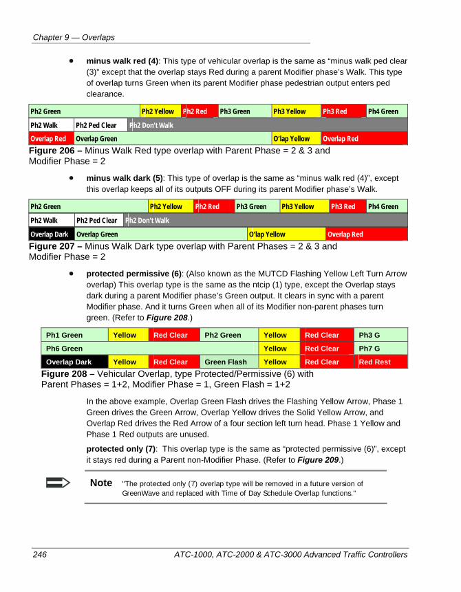
Chapter 9 — Overlaps
246 ATC-1000, ATC-2000 & ATC-3000 Advanced Traffic Controllers
minus walk red (4): This type of vehicular overlap is the same as “minus walk ped clear (3)” except that the overlap stays Red during a parent Modifier phase’s Walk. This type of overlap turns Green when its parent Modifier phase pedestrian output enters ped clearance.
Ph2 Green Ph2 Yellow Ph2 Red Ph3 Green Ph3 Yellow Ph3 Red Ph4 Green
Ph2 Walk Ph2 Ped Clear Ph2 Don’t Walk
Overlap Red Overlap Green O’lap Yellow Overlap Red Figure 206 – Minus Walk Red type overlap with Parent Phase = 2 & 3 and Modifier Phase = 2
minus walk dark (5): This type of overlap is the same as “minus walk red (4)”, except this overlap keeps all of its outputs OFF during its parent Modifier phase’s Walk.
Ph2 Green Ph2 Yellow Ph2 Red Ph3 Green Ph3 Yellow Ph3 Red Ph4 Green
Ph2 Walk Ph2 Ped Clear Ph2 Don’t Walk
Overlap Dark Overlap Green O’lap Yellow Overlap Red Figure 207 – Minus Walk Dark type overlap with Parent Phases = 2 & 3 and Modifier Phase = 2
protected permissive (6): (Also known as the MUTCD Flashing Yellow Left Turn Arrow overlap) This overlap type is the same as the ntcip (1) type, except the Overlap stays dark during a parent Modifier phase’s Green output. It clears in sync with a parent Modifier phase. And it turns Green when all of its Modifier non-parent phases turn green. (Refer to Figure 208.)
Ph1 Green Yellow Red Clear Ph2 Green Yellow Red Clear Ph3 G
Ph6 Green Yellow Red Clear Ph7 G
Overlap Dark Yellow Red Clear Green Flash Yellow Red Clear Red Rest Figure 208 – Vehicular Overlap, type Protected/Permissive (6) with Parent Phases = 1+2, Modifier Phase = 1, Green Flash = 1+2
In the above example, Overlap Green Flash drives the Flashing Yellow Arrow, Phase 1 Green drives the Green Arrow, Overlap Yellow drives the Solid Yellow Arrow, and Overlap Red drives the Red Arrow of a four section left turn head. Phase 1 Yellow and Phase 1 Red outputs are unused.
protected only (7): This overlap type is the same as “protected permissive (6)”, except it stays red during a Parent non-Modifier Phase. (Refer to Figure 209.)
Note "The protected only (7) overlap type will be removed in a future version of GreenWave and replaced with Time of Day Schedule Overlap functions."
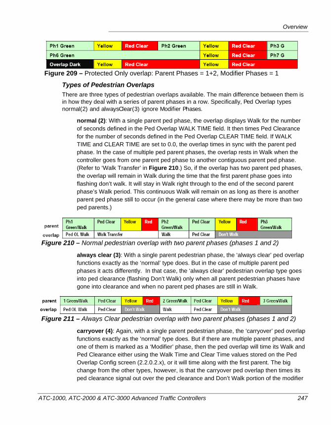
Overview
ATC-1000, ATC-2000 & ATC-3000 Advanced Traffic Controllers 247
Figure 209 – Protected Only overlap: Parent Phases = 1+2, Modifier Phases = 1
Types of Pedestrian Overlaps There are three types of pedestrian overlaps available. The main difference between them is in how they deal with a series of parent phases in a row. Specifically, Ped Overlap types normal(2) and alwaysClear(3) ignore Modifier Phases.
normal (2): With a single parent ped phase, the overlap displays Walk for the number of seconds defined in the Ped Overlap WALK TIME field. It then times Ped Clearance for the number of seconds defined in the Ped Overlap CLEAR TIME field. If WALK TIME and CLEAR TIME are set to 0.0, the overlap times in sync with the parent ped phase. In the case of multiple ped parent phases, the overlap rests in Walk when the controller goes from one parent ped phase to another contiguous parent ped phase. (Refer to ‘Walk Transfer’ in Figure 210.) So, if the overlap has two parent ped phases, the overlap will remain in Walk during the time that the first parent phase goes into flashing don’t walk. It will stay in Walk right through to the end of the second parent phase’s Walk period. This continuous Walk will remain on as long as there is another parent ped phase still to occur (in the general case where there may be more than two ped parents.)
Figure 210 – Normal pedestrian overlap with two parent phases (phases 1 and 2)
always clear (3): With a single parent pedestrian phase, the ‘always clear’ ped overlap functions exactly as the ‘normal’ type does. But in the case of multiple parent ped phases it acts differently. In that case, the ‘always clear’ pedestrian overlap type goes into ped clearance (flashing Don’t Walk) only when all parent pedestrian phases have gone into clearance and when no parent ped phases are still in Walk.
Figure 211 – Always Clear pedestrian overlap with two parent phases (phases 1 and 2)
carryover (4): Again, with a single parent pedestrian phase, the ‘carryover’ ped overlap functions exactly as the ‘normal’ type does. But if there are multiple parent phases, and one of them is marked as a ‘Modifier’ phase, then the ped overlap will time its Walk and Ped Clearance either using the Walk Time and Clear Time values stored on the Ped Overlap Config screen (2.2.0.2.x), or it will time along with the first parent. The big change from the other types, however, is that the carryover ped overlap then times its ped clearance signal out over the ped clearance and Don’t Walk portion of the modifier
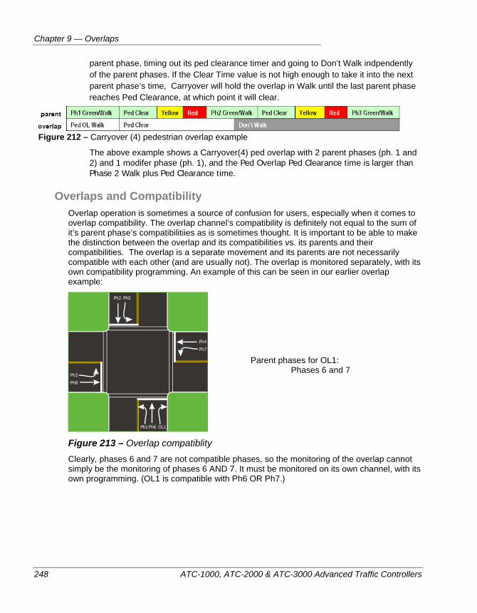
Chapter 9 — Overlaps
248 ATC-1000, ATC-2000 & ATC-3000 Advanced Traffic Controllers
parent phase, timing out its ped clearance timer and going to Don’t Walk indpendently of the parent phases. If the Clear Time value is not high enough to take it into the next parent phase’s time, Carryover will hold the overlap in Walk until the last parent phase reaches Ped Clearance, at which point it will clear.
Figure 212 – Carryover (4) pedestrian overlap example
The above example shows a Carryover(4) ped overlap with 2 parent phases (ph. 1 and 2) and 1 modifer phase (ph. 1), and the Ped Overlap Ped Clearance time is larger than Phase 2 Walk plus Ped Clearance time.
Overlaps and Compatibility Overlap operation is sometimes a source of confusion for users, especially when it comes to overlap compatibility. The overlap channel’s compatibility is definitely not equal to the sum of it’s parent phase’s compatibilitiies as is sometimes thought. It is important to be able to make the distinction between the overlap and its compatibilities vs. its parents and their compatibilities. The overlap is a separate movement and its parents are not necessarily compatible with each other (and are usually not). The overlap is monitored separately, with its own compatibility programming. An example of this can be seen in our earlier overlap example:
Figure 213 – Overlap compatiblity Clearly, phases 6 and 7 are not compatible phases, so the monitoring of the overlap cannot simply be the monitoring of phases 6 AND 7. It must be monitored on its own channel, with its own programming. (OL1 is compatible with Ph6 OR Ph7.)
Parent phases for OL1: Phases 6 and 7
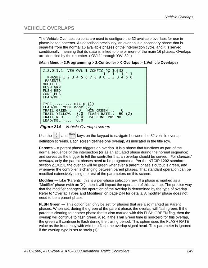
Vehicle Overlaps
ATC-1000, ATC-2000 & ATC-3000 Advanced Traffic Controllers 249
VEHICLE OVERLAPS
The Vehicle Overlaps screens are used to configure the 32 available overlaps for use in phase-based patterns. As described previously, an overlap is a secondary phase that is separate from the normal 16 available phases of the intersection cycle, and it is served conditionally, meaning that its state is linked to one or more of the main 16 phases. Overlaps are identified by their number. (‘OVL1’ through ‘OVL32’.)
(Main Menu > 2.Programming > 2.Controller > 0.Overlaps > 1.Vehicle Overlaps)
2.2.0.1.1 VEH OVL 1 CONFIG PG 1of32 1 1 1 1 1 1 1 PHASES 1 2 3 4 5 6 7 8 9 0 1 2 3 4 5 6 PARENTS MODIFIER FLSH GRN FLSH RED CONF PHS LEAD/DEL TYPE ........ ntcip (1) LEAD/DEL MODE none (2) TRAIL GREEN . 0 MIN GREEN .. 0 TRAIL YELLOW. 3.0 FLASH RATE.. 60 (2) TRAIL RED ... 0.0 USE CONF PHS NO LEAD/DEL .... 0.0
Figure 214 – Vehicle Overlaps screen
Use the and keys on the keypad to navigate between the 32 vehicle overlap definition screens. Each screen defines one overlap, as indicated in the title row.
Parents – A parent phase triggers an overlap. It is a phase that functions as part of the normal sequence of the intersection (or as an actuated phase during the normal sequence) and serves as the trigger to tell the controller that an overlap should be served. For standard overlaps, only the parent phases need to be programmed. Per the NTCIP 1202 standard, section 2.10.2.3, the overlap will be green whenever a parent phase’s output is green, and whenever the controller is changing between parent phases. That standard operation can be modified extensively using the rest of the parameters on this screen.
Modifier — Like ‘Parents’, this is a per-phase selection row. If a phase is marked as a ‘Modifier’ phase (with an ‘X’), then it will impact the operation of this overlap. The precise way that the modifier changes the operation of the overlap is determined by the type of overlap. Refer to “Overlap Types and Modifiers” on page 244 for details. A modifier phase does not need to be a parent phase.
FLSH Green — This option can only be set for phases that are also marked as Parent phases. When set, during the green of the parent phase, the overlap will flash green. If the parent is clearing to another phase that is also marked with this FLSH GREEN flag, then the overlap will continue to flash green. Also, if the Trail Green time is non-zero for this overlap, the green will continue to flash during the trailing period. This option uses the FLASH RATE value as the frequency with which to flash the overlap signal head. This parameter is ignored if the overlap type is set to ‘ntcip (1)’.
Chapter 9 — Overlaps
250 ATC-1000, ATC-2000 & ATC-3000 Advanced Traffic Controllers
FLSH Red — This option can be set for any phases, whether they are Parent phases or not. When set for a non-parent phase, the overlap will flash red during the phase’s green. If set for a parent phase, the overlap flashes red during the Red timed-out portion of the parent phase. This option uses the FLASH RATE value as the frequency with which to flash the overlap signal head. This parameter is ignored if the overlap type is set to ‘ntcip (1)’.
CONF Phs — These can be used to define which phases conflict with this overlap. These values are only used if the USE CONF PHS flag is set to YES. If that value is set to NO, then the overlap’s conflicting phases are automatically set to its parent phases’ conflicting phases. This parameter is ignored if the overlap type is set to ‘ntcip (1)’.
LEAD/DEL — Used to indicate which phases will use the Lead/Del logic and timer. These are basically ways that an overlap can be configured to lead (occur before) or be delayed (occur after) a parent phase. Refer to “Leading or Delayed Vehicular Overlaps” on page 251. This parameter is ignored if the overlap type is set to ‘ntcip (1)’.
Type – The type of overlap determines the logic that will be used by the overlap. The types of vehicular overlaps are described in “Overlap Types and Modifiers” on page 244. The ‘types’ are used to provide different ways for an overlap to respond to parent and modifier phases.
LEAD/DEL Mode — This setting determines which lead or delay logic will be used for all of the phases that are marked as LEAD/DEL in the array on the screen above. The available Lead/Del modes include: none (2) which cause no change in the overlap behavior, delay (3) which causes the overlap to be delayed relative to the parent phase, lead (4) which cause the overlap to start before the parent phase (at the start of the previous vehicular phase’s red rest period), and early lead (5) which causes the overlap to start even earlier prior to the parent phase (at the start of the previous phase's yellow clearance.) This parameter is ignored if the overlap type is set to ‘ntcip (1)’.
Trailing values (TRAIL GREEN, TRAIL YELLOW, TRAIL RED) – These numbers represent the time, in seconds, that the overlap signals are delayed (i.e. a double-clearing overlap) relative to the parent phase. A zero Trail Green Time turns the overlap yellow with the Parent Phase. A non-zero Trail Green time extends the overlap green when the Parent Phase turns yellow. Following Trail Green, the Overlap runs the Trail Yellow Time, the Trail Red Time and the next conflicting phases turn on. The terminating phase finishes Yellow and Red Clearance and compatible next phases turn on while the Overlap finishes Trail timing. Trail Yellow and Trail Red Range is 0-25.5 seconds and Trail Green Range is 0-255 seconds.
LEAD/DEL — This timer value is the number of seconds, in the range 0.0 to 25.5 seconds, that the overlap will lead or be delayed relative to the parent phase. This value determines how much Red Rest time will be added to the previous parent phase in order to accomodate a leading or early leading overlap, or how much green time will be added to the parent phase to accomodate a delay. This parameter is ignored if the overlap type is set to ‘ntcip (1)’.
MIN Green — The number of seconds, from 0 to 255, that represents the minimum amount of time a green signal should be shown during the overlap. If non-zero, the Min Green timing postpones a parent phase going yellow if not advancing to another parent phase. This parameter is ignored if the overlap type is set to ‘ntcip (1)’.
Flash Rate — The rate at which the overlap signal will flash, if the FLASH GREEN, FLASH YELLOW, or FLASH RED options are used. The available rates are: 60, 100, 150, or 300 flashes per minute. (i.e. rates of 1, 1.6, 2.5, or 5 Hz.) The internal values to set these are 2, 3, 4 or 5. This parameter is ignored if the overlap type is set to ‘ntcip (1)’.
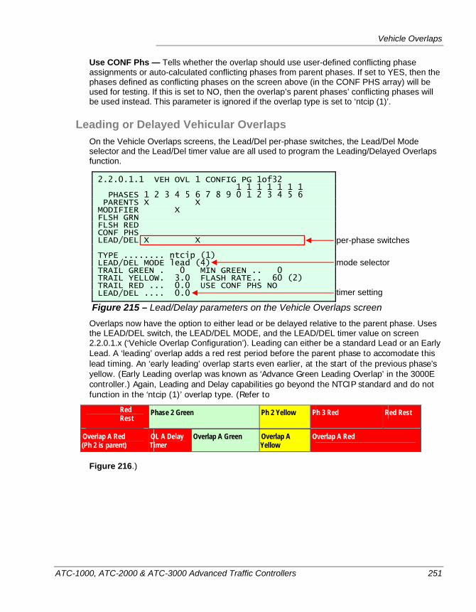
Vehicle Overlaps
ATC-1000, ATC-2000 & ATC-3000 Advanced Traffic Controllers 251
Use CONF Phs — Tells whether the overlap should use user-defined conflicting phase assignments or auto-calculated conflicting phases from parent phases. If set to YES, then the phases defined as conflicting phases on the screen above (in the CONF PHS array) will be used for testing. If this is set to NO, then the overlap’s parent phases’ conflicting phases will be used instead. This parameter is ignored if the overlap type is set to ‘ntcip (1)’.
Leading or Delayed Vehicular Overlaps On the Vehicle Overlaps screens, the Lead/Del per-phase switches, the Lead/Del Mode selector and the Lead/Del timer value are all used to program the Leading/Delayed Overlaps function.
2.2.0.1.1 VEH OVL 1 CONFIG PG 1of32 1 1 1 1 1 1 1 PHASES 1 2 3 4 5 6 7 8 9 0 1 2 3 4 5 6 PARENTS X X MODIFIER X FLSH GRN FLSH RED CONF PHS LEAD/DEL X X TYPE ........ ntcip (1) LEAD/DEL MODE lead (4) TRAIL GREEN . 0 MIN GREEN .. 0 TRAIL YELLOW. 3.0 FLASH RATE.. 60 (2) TRAIL RED ... 0.0 USE CONF PHS NO LEAD/DEL .... 0.0
Figure 215 – Lead/Delay parameters on the Vehicle Overlaps screen Overlaps now have the option to either lead or be delayed relative to the parent phase. Uses the LEAD/DEL switch, the LEAD/DEL MODE, and the LEAD/DEL timer value on screen 2.2.0.1.x (‘Vehicle Overlap Configuration’). Leading can either be a standard Lead or an Early Lead. A ‘leading’ overlap adds a red rest period before the parent phase to accomodate this lead timing. An ‘early leading’ overlap starts even earlier, at the start of the previous phase’s yellow. (Early Leading overlap was known as ‘Advance Green Leading Overlap’ in the 3000E controller.) Again, Leading and Delay capabilities go beyond the NTCIP standard and do not function in the ‘ntcip (1)’ overlap type. (Refer to
Red Rest
Phase 2 Green Ph 2 Yellow Ph 3 Red Red Rest
Overlap A Red (Ph 2 is parent)
OL A Delay Timer
Overlap A Green Overlap A Yellow
Overlap A Red
Figure 216.)
per-phase switches
mode selector
timer setting
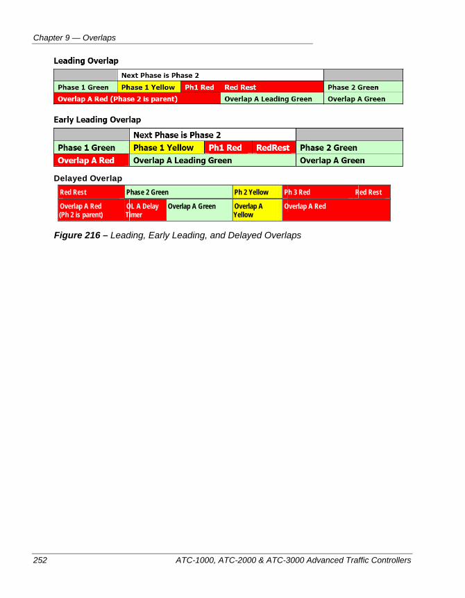
Chapter 9 — Overlaps
252 ATC-1000, ATC-2000 & ATC-3000 Advanced Traffic Controllers
Delayed Overlap
Red Rest Phase 2 Green Ph 2 Yellow Ph 3 Red Red Rest
Overlap A Red (Ph 2 is parent)
OL A Delay Timer
Overlap A Green Overlap A Yellow
Overlap A Red
Figure 216 – Leading, Early Leading, and Delayed Overlaps
Vehicle Overlaps
ATC-1000, ATC-2000 & ATC-3000 Advanced Traffic Controllers 253
Steps to Create an Overlap This is just to clarify how overlaps are actually activated and used. All that is needed to set up a vehicular overlap is:
1. Be sure that the controller is running a phase-based pattern. If an interval-based pattern is running, overlaps are not used.
2. Select an overlap number to implement by going to the Overlaps screen (MM > 2.Programming > 2.Controller > 0.Overlaps > 1.Vehicle Overlaps) and using the
and keys to navigate between the 32 that are available.
3. Go into Edit mode. ( - )
4. Once in the desired overlap screen, all that is required is that one or more parent phases be defined. For the overlap to be called, these selected parent phases must be served at some time during the operation of the controller.
5. All of the rest of the parameters on the Vehicle Overlaps screen are merely there to provide ways to ‘tweak’ the operation of the overlap. If you are happy with a standard overlap that follows the parent phases, just make sure that TYPE is set to ntcip(1) and you are done.
6. Press - again to exit from Edit mode, which saves the new overlap.
7. Go to the Overlaps Status screen to verify that the overlap runs as expected. (MM > 1.Status > 1.Controller Menu > 7. Overlaps > 1.Vehicle)
Warning The user must verify Lead/Delay and Minimum Green timing
does not disrupt Split timing and cause a Cycle Fault. The Coordinator does not Consistency Checks them.
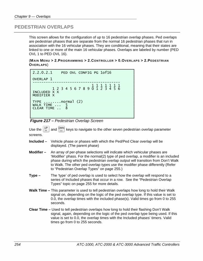
Chapter 9 — Overlaps
254 ATC-1000, ATC-2000 & ATC-3000 Advanced Traffic Controllers
PEDESTRIAN OVERLAPS
This screen allows for the configuration of up to 16 pedestrian overlap phases. Ped overlaps are pedestrian phases that are separate from the normal 16 pedestrian phases that run in association with the 16 vehicular phases. They are conditional, meaning that their states are linked to one or more of the main 16 vehicular phases. Overlaps are labeled by number (PED OVL 1 to PED OVL 16).
(MAIN MENU > 2.PROGRAMMING > 2.CONTROLLER > 0.OVERLAPS > 2.PEDESTRIAN OVERLAPS)
2.2.0.2.1 PED OVL CONFIG PG 1of16 OVERLAP 1 ---------------------------------------- 1 1 1 1 1 1 1 1 2 3 4 5 6 7 8 9 0 1 2 3 4 5 6 INCLUDED X X MODIFIER X TYPE ........normal (2) WALK TIME ... 5 CLEAR TIME .. 8
Figure 217 – Pedestrian Overlap Screen
Use the and keys to navigate to the other seven pedestrian overlap parameter screens.
Included – Vehicle phase or phases with which the Ped/Ped Clear overlap will be displayed. (The parent phase)
Modifier – An array of per-phase selections will indicate which vehicular phases are ‘Modifier’ phass. For the normal(2) type of ped overlap, a modifier is an included phase during which the pedestrian overlap output will transition from Don’t Walk to Walk. The other ped overlap types use the modifier phase differently (Refer to “Pedestrian Overlap Types” on page 255.)
Type – The ‘type’ of ped overlap is used to select how the overlap will respond to a series of Included phases that occur in a row. See the “Pedestrian Overlap Types” topic on page 255 for more details.
Walk Time – This parameter is used to tell pedestrian overlaps how long to hold their Walk signal on, depending on the logic of the ped overlap type. If this value is set to 0.0, the overlap times with the included phase(s). Valid times go from 0 to 255 seconds.
Clear Time – Used to tell pedestrian overlaps how long to hold their flashing Don’t Walk signal, again, depending on the logic of the ped overlap type being used. If this value is set to 0.0, the overlap times with the Included phases’ timers. Valid times go from 0 to 255 seconds.
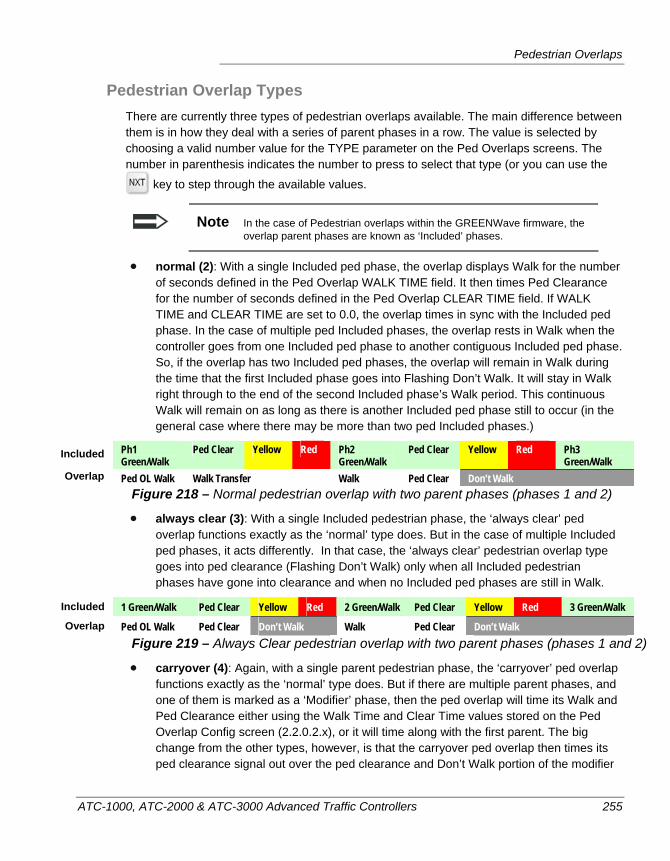
Pedestrian Overlaps
ATC-1000, ATC-2000 & ATC-3000 Advanced Traffic Controllers 255
Pedestrian Overlap Types There are currently three types of pedestrian overlaps available. The main difference between them is in how they deal with a series of parent phases in a row. The value is selected by choosing a valid number value for the TYPE parameter on the Ped Overlaps screens. The number in parenthesis indicates the number to press to select that type (or you can use the
key to step through the available values.
Note In the case of Pedestrian overlaps within the GREENWave firmware, the overlap parent phases are known as ‘Included’ phases.
normal (2): With a single Included ped phase, the overlap displays Walk for the number of seconds defined in the Ped Overlap WALK TIME field. It then times Ped Clearance for the number of seconds defined in the Ped Overlap CLEAR TIME field. If WALK TIME and CLEAR TIME are set to 0.0, the overlap times in sync with the Included ped phase. In the case of multiple ped Included phases, the overlap rests in Walk when the controller goes from one Included ped phase to another contiguous Included ped phase. So, if the overlap has two Included ped phases, the overlap will remain in Walk during the time that the first Included phase goes into Flashing Don’t Walk. It will stay in Walk right through to the end of the second Included phase’s Walk period. This continuous Walk will remain on as long as there is another Included ped phase still to occur (in the general case where there may be more than two ped Included phases.)
Ph1 Green/Walk
Ped Clear Yellow Red Ph2 Green/Walk
Ped Clear Yellow Red Ph3 Green/Walk
Ped OL Walk Walk Transfer Walk Ped Clear Don’t Walk Figure 218 – Normal pedestrian overlap with two parent phases (phases 1 and 2)
always clear (3): With a single Included pedestrian phase, the ‘always clear’ ped overlap functions exactly as the ‘normal’ type does. But in the case of multiple Included ped phases, it acts differently. In that case, the ‘always clear’ pedestrian overlap type goes into ped clearance (Flashing Don’t Walk) only when all Included pedestrian phases have gone into clearance and when no Included ped phases are still in Walk.
1 Green/Walk Ped Clear Yellow Red 2 Green/Walk Ped Clear Yellow Red 3 Green/Walk
Ped OL Walk Ped Clear Don’t Walk Walk Ped Clear Don’t Walk Figure 219 – Always Clear pedestrian overlap with two parent phases (phases 1 and 2)
carryover (4): Again, with a single parent pedestrian phase, the ‘carryover’ ped overlap functions exactly as the ‘normal’ type does. But if there are multiple parent phases, and one of them is marked as a ‘Modifier’ phase, then the ped overlap will time its Walk and Ped Clearance either using the Walk Time and Clear Time values stored on the Ped Overlap Config screen (2.2.0.2.x), or it will time along with the first parent. The big change from the other types, however, is that the carryover ped overlap then times its ped clearance signal out over the ped clearance and Don’t Walk portion of the modifier
Included
Overlap
Overlap
Included
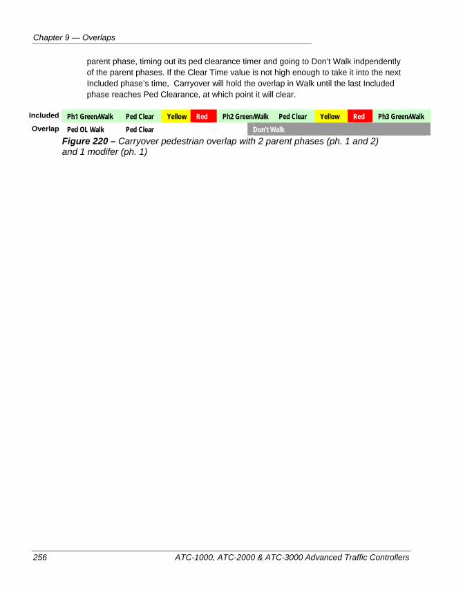
Chapter 9 — Overlaps
256 ATC-1000, ATC-2000 & ATC-3000 Advanced Traffic Controllers
parent phase, timing out its ped clearance timer and going to Don’t Walk indpendently of the parent phases. If the Clear Time value is not high enough to take it into the next Included phase’s time, Carryover will hold the overlap in Walk until the last Included phase reaches Ped Clearance, at which point it will clear.
Ph1 Green/Walk Ped Clear Yellow Red Ph2 Green/Walk Ped Clear Yellow Red Ph3 Green/Walk
Ped OL Walk Ped Clear Don’t Walk Figure 220 – Carryover pedestrian overlap with 2 parent phases (ph. 1 and 2) and 1 modifer (ph. 1)
Overlap
Included
Pedestrian Overlaps
ATC-1000, ATC-2000 & ATC-3000 Advanced Traffic Controllers 257
Steps to Create a Ped Overlap Follow these steps to create a Pedestrian Overlap phase:
1. Be sure that the controller is running a phase-based pattern. If an interval-based pattern is running, overlaps (both vehicular and pedestrian) are not used.
2. Select a ped overlap number to implement by going to the Overlaps menu (MM > 2.Programming > 2.Controller > 0.Overlaps), opening the Pedestrian Overlaps
screens, and using the and keys to navigate between the 16 that are available.
3. Go into Edit mode. ( - )
4. Once in the desired ped overlap screen, all that is required is that one or more Included phase be defined. For the ped overlap to be called, these selected Included Phase Peds must be served at some time during the operation of the controller.
5. All of the rest of the parameters on the Ped Overlaps screens are merely there to provide ways to ‘tweak’ the operation of the overlap. If you are happy with a standard ped overlap that follows the parent phases, just make sure that TYPE is set to normal (2) and you are done.
6. Press - again to exit from Edit mode, which saves the new pedestrian overlap phase.
7. Go to the Overlaps Status screen to verify that the ped overlap runs as expected. (MM > 1.Status > 1.Controller Menu > 7. Overlaps > 2.Pedestrian)
Warning The user must verify Ped Overlaps do not disrupt Split timing
and cause a Cycle Fault. The Coordinator does not Consistency Check them.

Chapter 9 — Overlaps
258 ATC-1000, ATC-2000 & ATC-3000 Advanced Traffic Controllers
ATC-1000, ATC-2000 & ATC-3000 Advanced Traffic Controllers 259
Chapter 10 — Transit Signal Priority
This chapter describes how to set up transit signal priority in an ATC controller. The following topics are discussed in detail in this chapter:
• An introduction to what TSP is, on page 260
• A discussion of how TSP is implemented in the ATC, on page 261
• A quick description of how to set up TSP, on page 264
• A detailed description of the ATC TSP screens and parameters, starting on page 266
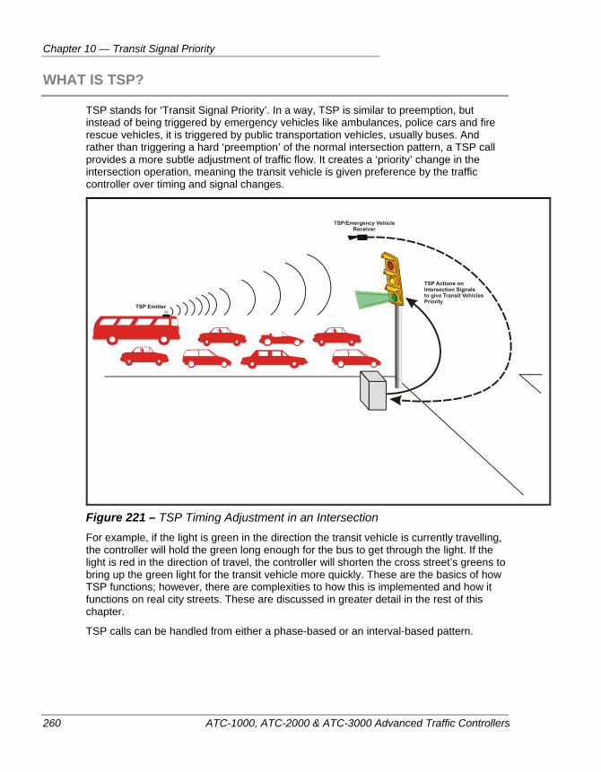
Chapter 10 — Transit Signal Priority
260 ATC-1000, ATC-2000 & ATC-3000 Advanced Traffic Controllers
WHAT IS TSP?
TSP stands for ‘Transit Signal Priority’. In a way, TSP is similar to preemption, but instead of being triggered by emergency vehicles like ambulances, police cars and fire rescue vehicles, it is triggered by public transportation vehicles, usually buses. And rather than triggering a hard ‘preemption’ of the normal intersection pattern, a TSP call provides a more subtle adjustment of traffic flow. It creates a ‘priority’ change in the intersection operation, meaning the transit vehicle is given preference by the traffic controller over timing and signal changes.
Figure 221 – TSP Timing Adjustment in an Intersection For example, if the light is green in the direction the transit vehicle is currently travelling, the controller will hold the green long enough for the bus to get through the light. If the light is red in the direction of travel, the controller will shorten the cross street’s greens to bring up the green light for the transit vehicle more quickly. These are the basics of how TSP functions; however, there are complexities to how this is implemented and how it functions on real city streets. These are discussed in greater detail in the rest of this chapter.
TSP calls can be handled from either a phase-based or an interval-based pattern.
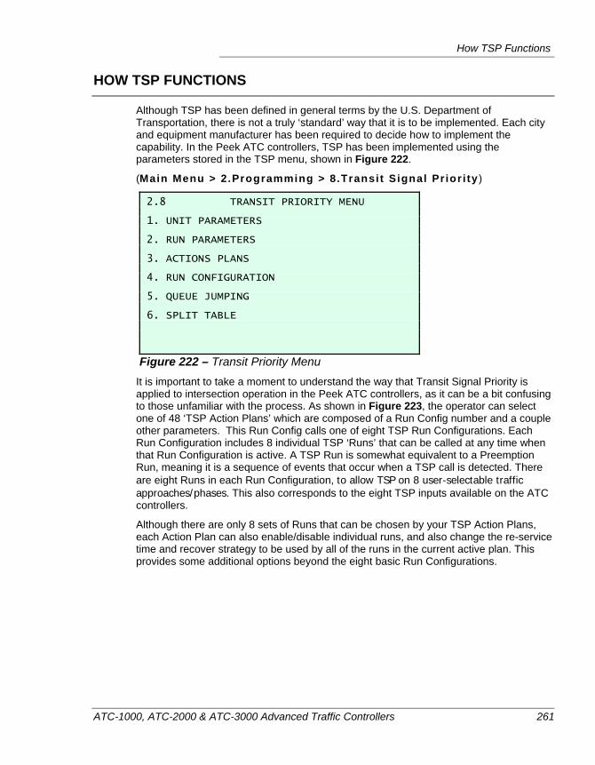
How TSP Functions
ATC-1000, ATC-2000 & ATC-3000 Advanced Traffic Controllers 261
HOW TSP FUNCTIONS
Although TSP has been defined in general terms by the U.S. Department of Transportation, there is not a truly ‘standard’ way that it is to be implemented. Each city and equipment manufacturer has been required to decide how to implement the capability. In the Peek ATC controllers, TSP has been implemented using the parameters stored in the TSP menu, shown in Figure 222.
(Main Menu > 2.Programming > 8.Transi t Signal Pr ior i ty )
2.8 TRANSIT PRIORITY MENU 1. UNIT PARAMETERS 2. RUN PARAMETERS 3. ACTIONS PLANS 4. RUN CONFIGURATION 5. QUEUE JUMPING 6. SPLIT TABLE
Figure 222 – Transit Priority Menu It is important to take a moment to understand the way that Transit Signal Priority is applied to intersection operation in the Peek ATC controllers, as it can be a bit confusing to those unfamiliar with the process. As shown in Figure 223, the operator can select one of 48 ‘TSP Action Plans’ which are composed of a Run Config number and a couple other parameters. This Run Config calls one of eight TSP Run Configurations. Each Run Configuration includes 8 individual TSP ‘Runs’ that can be called at any time when that Run Configuration is active. A TSP Run is somewhat equivalent to a Preemption Run, meaning it is a sequence of events that occur when a TSP call is detected. There are eight Runs in each Run Configuration, to allow TSP on 8 user-selectable traffic approaches/phases. This also corresponds to the eight TSP inputs available on the ATC controllers.
Although there are only 8 sets of Runs that can be chosen by your TSP Action Plans, each Action Plan can also enable/disable individual runs, and also change the re-service time and recover strategy to be used by all of the runs in the current active plan. This provides some additional options beyond the eight basic Run Configurations.
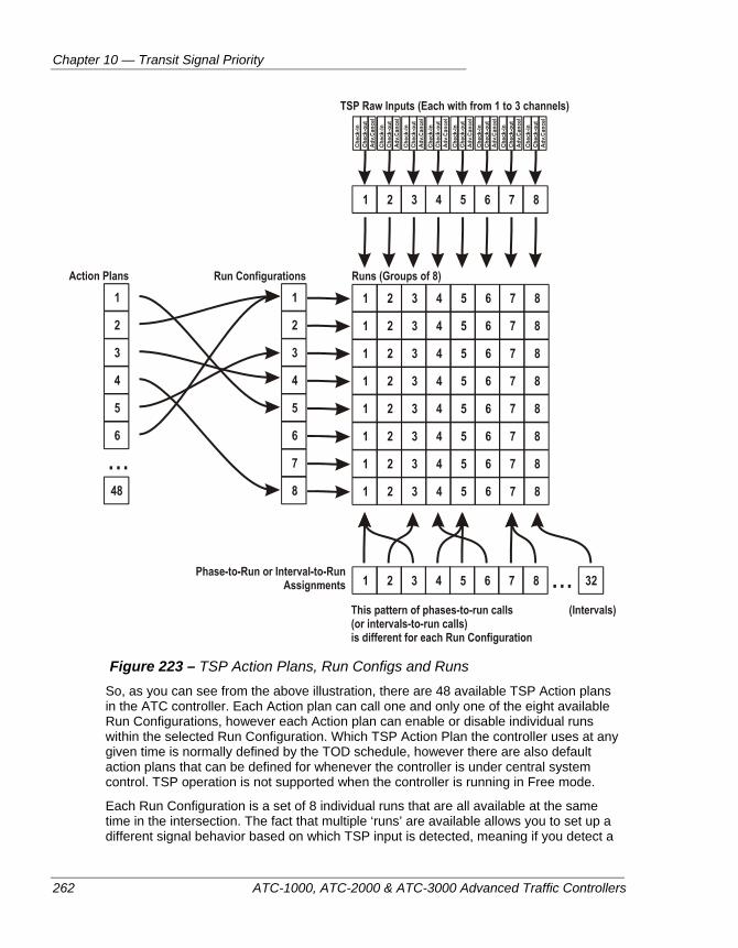
Chapter 10 — Transit Signal Priority
262 ATC-1000, ATC-2000 & ATC-3000 Advanced Traffic Controllers
Figure 223 – TSP Action Plans, Run Configs and Runs
So, as you can see from the above illustration, there are 48 available TSP Action plans in the ATC controller. Each Action plan can call one and only one of the eight available Run Configurations, however each Action plan can enable or disable individual runs within the selected Run Configuration. Which TSP Action Plan the controller uses at any given time is normally defined by the TOD schedule, however there are also default action plans that can be defined for whenever the controller is under central system control. TSP operation is not supported when the controller is running in Free mode.
Each Run Configuration is a set of 8 individual runs that are all available at the same time in the intersection. The fact that multiple ‘runs’ are available allows you to set up a different signal behavior based on which TSP input is detected, meaning if you detect a
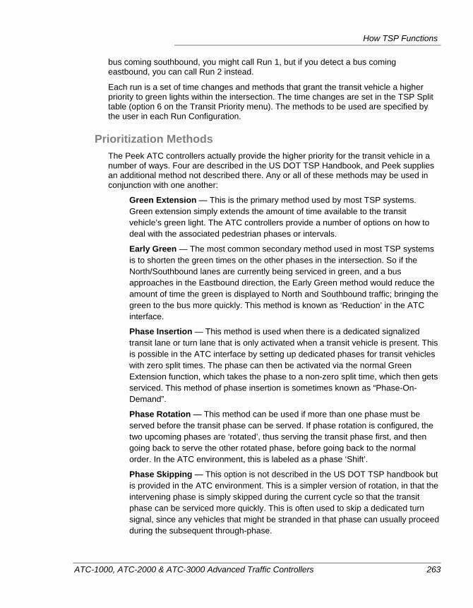
How TSP Functions
ATC-1000, ATC-2000 & ATC-3000 Advanced Traffic Controllers 263
bus coming southbound, you might call Run 1, but if you detect a bus coming eastbound, you can call Run 2 instead.
Each run is a set of time changes and methods that grant the transit vehicle a higher priority to green lights within the intersection. The time changes are set in the TSP Split table (option 6 on the Transit Priority menu). The methods to be used are specified by the user in each Run Configuration.
Prioritization Methods The Peek ATC controllers actually provide the higher priority for the transit vehicle in a number of ways. Four are described in the US DOT TSP Handbook, and Peek supplies an additional method not described there. Any or all of these methods may be used in conjunction with one another:
Green Extension — This is the primary method used by most TSP systems. Green extension simply extends the amount of time available to the transit vehicle’s green light. The ATC controllers provide a number of options on how to deal with the associated pedestrian phases or intervals.
Early Green — The most common secondary method used in most TSP systems is to shorten the green times on the other phases in the intersection. So if the North/Southbound lanes are currently being serviced in green, and a bus approaches in the Eastbound direction, the Early Green method would reduce the amount of time the green is displayed to North and Southbound traffic; bringing the green to the bus more quickly. This method is known as ‘Reduction’ in the ATC interface.
Phase Insertion — This method is used when there is a dedicated signalized transit lane or turn lane that is only activated when a transit vehicle is present. This is possible in the ATC interface by setting up dedicated phases for transit vehicles with zero split times. The phase can then be activated via the normal Green Extension function, which takes the phase to a non-zero split time, which then gets serviced. This method of phase insertion is sometimes known as “Phase-On-Demand”.
Phase Rotation — This method can be used if more than one phase must be served before the transit phase can be served. If phase rotation is configured, the two upcoming phases are ‘rotated’, thus serving the transit phase first, and then going back to serve the other rotated phase, before going back to the normal order. In the ATC environment, this is labeled as a phase ‘Shift’.
Phase Skipping — This option is not described in the US DOT TSP handbook but is provided in the ATC environment. This is a simpler version of rotation, in that the intervening phase is simply skipped during the current cycle so that the transit phase can be serviced more quickly. This is often used to skip a dedicated turn signal, since any vehicles that might be stranded in that phase can usually proceed during the subsequent through-phase.
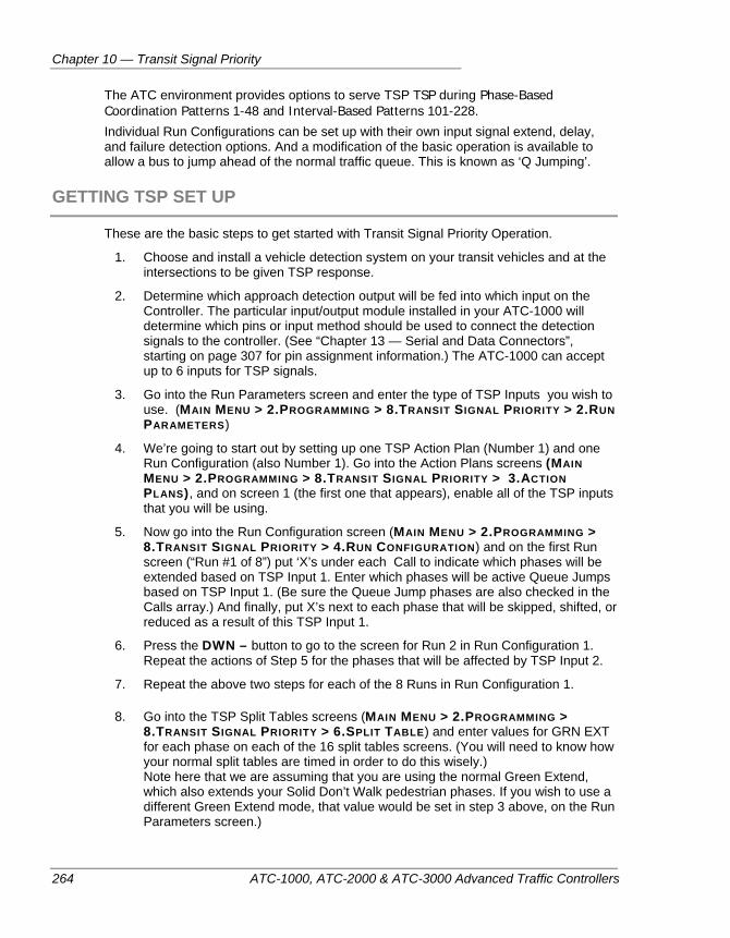
Chapter 10 — Transit Signal Priority
264 ATC-1000, ATC-2000 & ATC-3000 Advanced Traffic Controllers
The ATC environment provides options to serve TSP TSP during Phase-Based Coordination Patterns 1-48 and Interval-Based Patterns 101-228. Individual Run Configurations can be set up with their own input signal extend, delay, and failure detection options. And a modification of the basic operation is available to allow a bus to jump ahead of the normal traffic queue. This is known as ‘Q Jumping’.
GETTING TSP SET UP
These are the basic steps to get started with Transit Signal Priority Operation.
1. Choose and install a vehicle detection system on your transit vehicles and at the intersections to be given TSP response.
2. Determine which approach detection output will be fed into which input on the Controller. The particular input/output module installed in your ATC-1000 will determine which pins or input method should be used to connect the detection signals to the controller. (See “Chapter 13 — Serial and Data Connectors”, starting on page 307 for pin assignment information.) The ATC-1000 can accept up to 6 inputs for TSP signals.
3. Go into the Run Parameters screen and enter the type of TSP Inputs you wish to use. (MAIN MENU > 2.PROGRAMMING > 8.TRANSIT SIGNAL PRIORITY > 2.RUN PARAMETERS)
4. We’re going to start out by setting up one TSP Action Plan (Number 1) and one Run Configuration (also Number 1). Go into the Action Plans screens (MAIN MENU > 2.PROGRAMMING > 8.TRANSIT SIGNAL PRIORITY > 3.ACTION PLANS), and on screen 1 (the first one that appears), enable all of the TSP inputs that you will be using.
5. Now go into the Run Configuration screen (MAIN MENU > 2.PROGRAMMING > 8.TRANSIT SIGNAL PRIORITY > 4.RUN CONFIGURATION) and on the first Run screen (“Run #1 of 8”) put ‘X’s under each Call to indicate which phases will be extended based on TSP Input 1. Enter which phases will be active Queue Jumps based on TSP Input 1. (Be sure the Queue Jump phases are also checked in the Calls array.) And finally, put X’s next to each phase that will be skipped, shifted, or reduced as a result of this TSP Input 1.
6. Press the DWN – button to go to the screen for Run 2 in Run Configuration 1. Repeat the actions of Step 5 for the phases that will be affected by TSP Input 2.
7. Repeat the above two steps for each of the 8 Runs in Run Configuration 1.
8. Go into the TSP Split Tables screens (MAIN MENU > 2.PROGRAMMING > 8.TRANSIT SIGNAL PRIORITY > 6.SPLIT TABLE) and enter values for GRN EXT for each phase on each of the 16 split tables screens. (You will need to know how your normal split tables are timed in order to do this wisely.) Note here that we are assuming that you are using the normal Green Extend, which also extends your Solid Don’t Walk pedestrian phases. If you wish to use a different Green Extend mode, that value would be set in step 3 above, on the Run Parameters screen.)
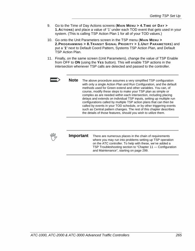
Getting TSP Set Up
ATC-1000, ATC-2000 & ATC-3000 Advanced Traffic Controllers 265
9. Go to the Time of Day Actions screens (MAIN MENU > 4.TIME OF DAY > 1.ACTIONS) and place a value of ‘1’ under each TOD event that gets used in your system. (This is calling TSP Action Plan 1 for all of your TOD values.)
10. Go onto the Unit Parameters screen in the TSP menu (MAIN MENU > 2.PROGRAMMING > 8.TRANSIT SIGNAL PRIORITY > 1.UNIT PARAMETERS) and put a ‘1’ next to Default Coord Pattern, Systems TSP Action Plan, and Default TSP Action Plan.
11. Finally, on the same screen (Unit Parameters), change the value of TSP Enable from OFF to ON (using the YES button). This will enable TSP actions in the intersection whenever TSP calls are detected and passed to the controller.
Note The above procedure assumes a very simplified TSP configuration with only a single Action Plan and Run Configuration, and the default methods used for Green extend and other variables. You can, of course, modify these steps to make your TSP plan as simple or complex as are needed within each intersection, including placing delays and extends on individual TSP inputs, setting up multiple run configurations called by multiple TSP action plans that can then be called by events in your TOD schedule, or by other triggering events such as Central pattern changes. The rest of this chapter describes the details of those features, should you wish to utilize them.
Important There are numerous places in the chain of requirements
where you may run into problems setting up TSP operation on the ATC controller. To help with these, we’ve added a TSP Troubleshooting section to “Chapter 11 — Configuration and Maintenance”, starting on page 299.
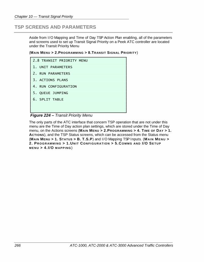
Chapter 10 — Transit Signal Priority
266 ATC-1000, ATC-2000 & ATC-3000 Advanced Traffic Controllers
TSP SCREENS AND PARAMETERS
Aside from I/O Mapping and Time of Day TSP Action Plan enabling, all of the parameters and screens used to set up Transit Signal Priority on a Peek ATC controller are located under the Transit Priority Menu
(MAIN MENU > 2.PROGRAMMING > 8.TRANSIT SIGNAL PRIORITY)
2.8 TRANSIT PRIORITY MENU 1. UNIT PARAMETERS 2. RUN PARAMETERS 3. ACTIONS PLANS 4. RUN CONFIGURATION 5. QUEUE JUMPING 6. SPLIT TABLE
Figure 224 – Transit Priority Menu The only parts of the ATC interface that concern TSP operation that are not under this menu are the Time of Day action plan settings, which are stored under the Time of Day menu, on the Actions screens (MAIN MENU > 2.PROGRAMMING > 4. TIME OF DAY > 1. ACTIONS), and the TSP Status screens, which can be accessed from the Status menu (MAIN MENU > 1. STATUS > B. T.S.P) and I/O Mapping TSP Inputs. (MAI N ME N U > 2 . PR OG R AM M I NG > 1.UNI T CO N FI G U R AT I O N > 5.CO M M S AN D I /O SE T U P M EN U > 4. I /O M AP P I NG )
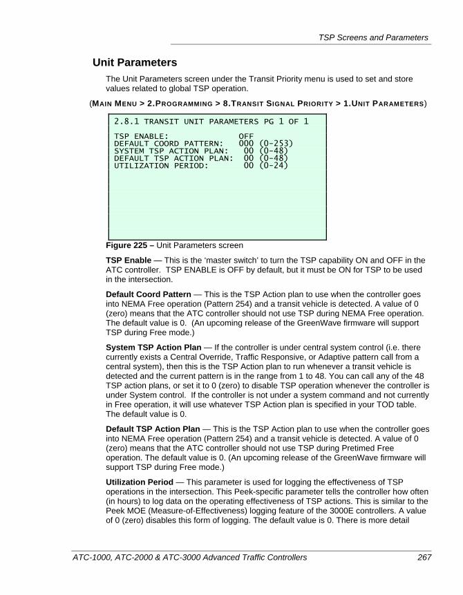
TSP Screens and Parameters
ATC-1000, ATC-2000 & ATC-3000 Advanced Traffic Controllers 267
Unit Parameters The Unit Parameters screen under the Transit Priority menu is used to set and store values related to global TSP operation.
(MAIN MENU > 2.PROGRAMMING > 8.TRANSIT SIGNAL PRIORITY > 1.UNIT PARAMETERS)
2.8.1 TRANSIT UNIT PARAMETERS PG 1 OF 1 TSP ENABLE: OFF DEFAULT COORD PATTERN: 000 (0-253) SYSTEM TSP ACTION PLAN: 00 (0-48) DEFAULT TSP ACTION PLAN: 00 (0-48) UTILIZATION PERIOD: 00 (0-24)
Figure 225 – Unit Parameters screen
TSP Enable — This is the ‘master switch’ to turn the TSP capability ON and OFF in the ATC controller. TSP ENABLE is OFF by default, but it must be ON for TSP to be used in the intersection.
Default Coord Pattern — This is the TSP Action plan to use when the controller goes into NEMA Free operation (Pattern 254) and a transit vehicle is detected. A value of 0 (zero) means that the ATC controller should not use TSP during NEMA Free operation. The default value is 0. (An upcoming release of the GreenWave firmware will support TSP during Free mode.)
System TSP Action Plan — If the controller is under central system control (i.e. there currently exists a Central Override, Traffic Responsive, or Adaptive pattern call from a central system), then this is the TSP Action plan to run whenever a transit vehicle is detected and the current pattern is in the range from 1 to 48. You can call any of the 48 TSP action plans, or set it to 0 (zero) to disable TSP operation whenever the controller is under System control. If the controller is not under a system command and not currently in Free operation, it will use whatever TSP Action plan is specified in your TOD table. The default value is 0.
Default TSP Action Plan — This is the TSP Action plan to use when the controller goes into NEMA Free operation (Pattern 254) and a transit vehicle is detected. A value of 0 (zero) means that the ATC controller should not use TSP during Pretimed Free operation. The default value is 0. (An upcoming release of the GreenWave firmware will support TSP during Free mode.)
Utilization Period — This parameter is used for logging the effectiveness of TSP operations in the intersection. This Peek-specific parameter tells the controller how often (in hours) to log data on the operating effectiveness of TSP actions. This is similar to the Peek MOE (Measure-of-Effectiveness) logging feature of the 3000E controllers. A value of 0 (zero) disables this form of logging. The default value is 0. There is more detail
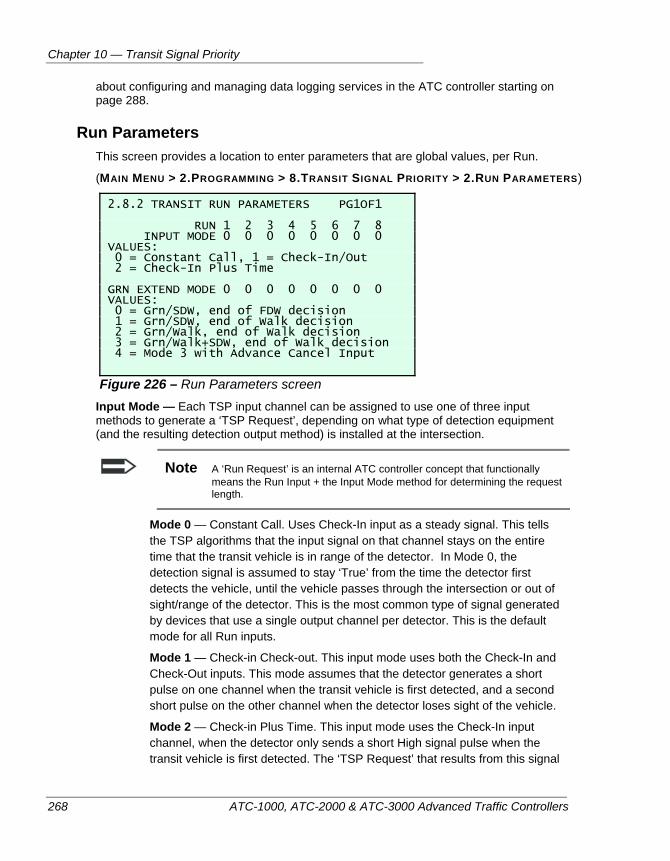
Chapter 10 — Transit Signal Priority
268 ATC-1000, ATC-2000 & ATC-3000 Advanced Traffic Controllers
about configuring and managing data logging services in the ATC controller starting on page 288.
Run Parameters This screen provides a location to enter parameters that are global values, per Run.
(MAIN MENU > 2.PROGRAMMING > 8.TRANSIT SIGNAL PRIORITY > 2.RUN PARAMETERS)
2.8.2 TRANSIT RUN PARAMETERS PG1OF1 RUN 1 2 3 4 5 6 7 8 INPUT MODE 0 0 0 0 0 0 0 0 VALUES: 0 = Constant Call, 1 = Check-In/Out 2 = Check-In Plus Time GRN EXTEND MODE 0 0 0 0 0 0 0 0 VALUES: 0 = Grn/SDW, end of FDW decision 1 = Grn/SDW, end of Walk decision 2 = Grn/Walk, end of Walk decision 3 = Grn/Walk+SDW, end of Walk decision 4 = Mode 3 with Advance Cancel Input
Figure 226 – Run Parameters screen Input Mode — Each TSP input channel can be assigned to use one of three input methods to generate a ‘TSP Request’, depending on what type of detection equipment (and the resulting detection output method) is installed at the intersection.
Note A ‘Run Request’ is an internal ATC controller concept that functionally means the Run Input + the Input Mode method for determining the request length.
Mode 0 — Constant Call. Uses Check-In input as a steady signal. This tells the TSP algorithms that the input signal on that channel stays on the entire time that the transit vehicle is in range of the detector. In Mode 0, the detection signal is assumed to stay ‘True’ from the time the detector first detects the vehicle, until the vehicle passes through the intersection or out of sight/range of the detector. This is the most common type of signal generated by devices that use a single output channel per detector. This is the default mode for all Run inputs.
Mode 1 — Check-in Check-out. This input mode uses both the Check-In and Check-Out inputs. This mode assumes that the detector generates a short pulse on one channel when the transit vehicle is first detected, and a second short pulse on the other channel when the detector loses sight of the vehicle.
Mode 2 — Check-in Plus Time. This input mode uses the Check-In input channel, when the detector only sends a short High signal pulse when the transit vehicle is first detected. The ‘TSP Request’ that results from this signal
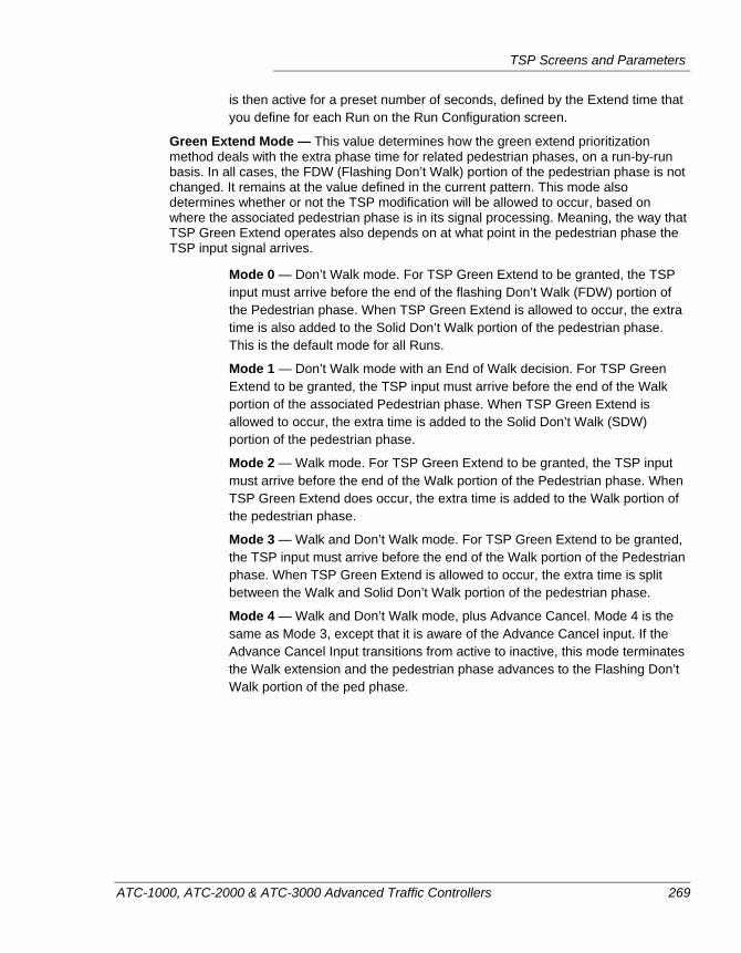
TSP Screens and Parameters
ATC-1000, ATC-2000 & ATC-3000 Advanced Traffic Controllers 269
is then active for a preset number of seconds, defined by the Extend time that you define for each Run on the Run Configuration screen.
Green Extend Mode — This value determines how the green extend prioritization method deals with the extra phase time for related pedestrian phases, on a run-by-run basis. In all cases, the FDW (Flashing Don’t Walk) portion of the pedestrian phase is not changed. It remains at the value defined in the current pattern. This mode also determines whether or not the TSP modification will be allowed to occur, based on where the associated pedestrian phase is in its signal processing. Meaning, the way that TSP Green Extend operates also depends on at what point in the pedestrian phase the TSP input signal arrives.
Mode 0 — Don’t Walk mode. For TSP Green Extend to be granted, the TSP input must arrive before the end of the flashing Don’t Walk (FDW) portion of the Pedestrian phase. When TSP Green Extend is allowed to occur, the extra time is also added to the Solid Don’t Walk portion of the pedestrian phase. This is the default mode for all Runs.
Mode 1 — Don’t Walk mode with an End of Walk decision. For TSP Green Extend to be granted, the TSP input must arrive before the end of the Walk portion of the associated Pedestrian phase. When TSP Green Extend is allowed to occur, the extra time is added to the Solid Don’t Walk (SDW) portion of the pedestrian phase.
Mode 2 — Walk mode. For TSP Green Extend to be granted, the TSP input must arrive before the end of the Walk portion of the Pedestrian phase. When TSP Green Extend does occur, the extra time is added to the Walk portion of the pedestrian phase.
Mode 3 — Walk and Don’t Walk mode. For TSP Green Extend to be granted, the TSP input must arrive before the end of the Walk portion of the Pedestrian phase. When TSP Green Extend is allowed to occur, the extra time is split between the Walk and Solid Don’t Walk portion of the pedestrian phase.
Mode 4 — Walk and Don’t Walk mode, plus Advance Cancel. Mode 4 is the same as Mode 3, except that it is aware of the Advance Cancel input. If the Advance Cancel Input transitions from active to inactive, this mode terminates the Walk extension and the pedestrian phase advances to the Flashing Don’t Walk portion of the ped phase.
Chapter 10 — Transit Signal Priority
270 ATC-1000, ATC-2000 & ATC-3000 Advanced Traffic Controllers
TSP Action Plans Option 3 under the Transit Priority menu is where TSP Action Plans are defined. Use the
and keys to switch between the 48 available action plan definition screens.
(MAIN MENU > 2.PROGRAMMING > 8.TRANSIT SIGNAL PRIORITY > 3.ACTION PLANS)
2.8.3 TRANSIT ACTION PLAN 1 OF 48 RUN # 1 2 3 4 5 6 7 8 Run Enable: Run Configuration: 001 (1-8) Master Reservice Time: 00000 (0-65535) Recovery Strategy: 0 (0-3) 0 = Normal 1 = Offset Correction 2 = Offset Correction TSP-Phase Delayed 3 = Split Balance
Figure 227 – TSP Action Plan screen Run Enable settings — In each of the 48 TSP action plans, it is possible to disable one or more of the 8 available runs in the selected Run Configuration (See next item). Place an ‘X’ under the run number (by pressing the YES button) to enable that run. By default, all runs are disabled.
Run Config — This is where one of the eight available Run Configurations is chosen for use in this TSP Action plan. This tells the action plan which set of 8 Runs will be available in the intersection while this Action Plan is in effect. The default value is Run Config = 1.
Master Reservice Time — Reservice time is the amount of time that the controller locks out all additional TSP requests after completion of a TSP Run. A value of 0 (zero) means that this reservice limit is deactivated, meaning a second TSP call will be accepted immediately after the first call. This is the ‘Master’ reservice time. Note that there is also a reservice time value associated with each Run Configuration. Whichever value is greater (either the Master Reservice Time stored here in the selected Action Plan, or the Reservice Time stored in the associated Run Configuration) will be the active requirement in the intersection. Applies only if the TSP request adjusts phase times.
Recovery Strategy — This is a parameter that is only used with the ambient pattern that the TSP action interrupts is a NEMA coordinated pattern. It defines how the controller will respond after the transit vehicle has gone through the intersection to recover from the changed timing, and its effect on coordinated operation. The four possible modes are:
Mode 0 — ‘Normal’ recovery. TSP restores a negative offset error by extending splits and restores a positive offset error by reducing splits, using Menu 2.8.6 TSP Split Table Grn Ext (Extend) and Grn Rdc (Reduce) Times.
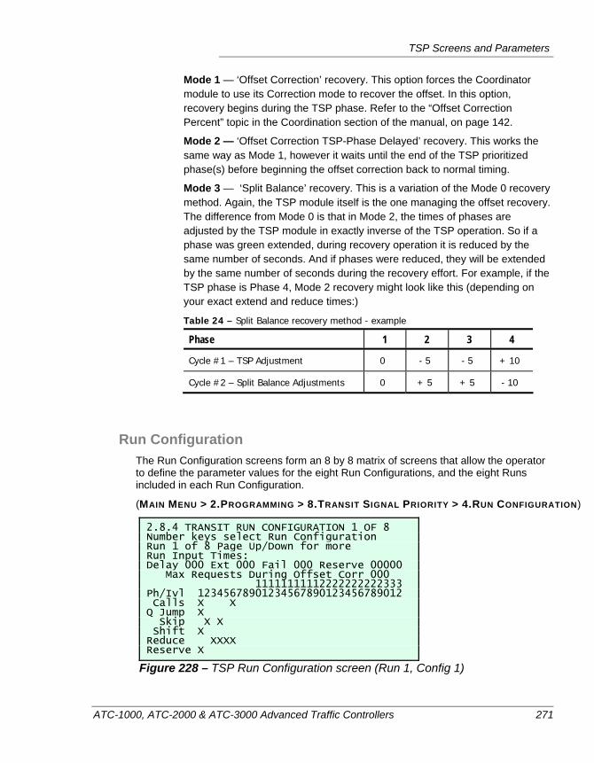
TSP Screens and Parameters
ATC-1000, ATC-2000 & ATC-3000 Advanced Traffic Controllers 271
Mode 1 — ‘Offset Correction’ recovery. This option forces the Coordinator module to use its Correction mode to recover the offset. In this option, recovery begins during the TSP phase. Refer to the “Offset Correction Percent” topic in the Coordination section of the manual, on page 142.
Mode 2 — ‘Offset Correction TSP-Phase Delayed’ recovery. This works the same way as Mode 1, however it waits until the end of the TSP prioritized phase(s) before beginning the offset correction back to normal timing.
Mode 3 — ‘Split Balance’ recovery. This is a variation of the Mode 0 recovery method. Again, the TSP module itself is the one managing the offset recovery. The difference from Mode 0 is that in Mode 2, the times of phases are adjusted by the TSP module in exactly inverse of the TSP operation. So if a phase was green extended, during recovery operation it is reduced by the same number of seconds. And if phases were reduced, they will be extended by the same number of seconds during the recovery effort. For example, if the TSP phase is Phase 4, Mode 2 recovery might look like this (depending on your exact extend and reduce times:)
Table 24 – Split Balance recovery method - example
Phase 1 2 3 4
Cycle #1 – TSP Adjustment 0 - 5 - 5 + 10
Cycle #2 – Split Balance Adjustments 0 + 5 + 5 - 10
Run Configuration The Run Configuration screens form an 8 by 8 matrix of screens that allow the operator to define the parameter values for the eight Run Configurations, and the eight Runs included in each Run Configuration.
(MAIN MENU > 2.PROGRAMMING > 8.TRANSIT SIGNAL PRIORITY > 4.RUN CONFIGURATION)
2.8.4 TRANSIT RUN CONFIGURATION 1 OF 8 Number keys select Run Configuration Run 1 of 8 Page Up/Down for more Run Input Times: Delay 000 Ext 000 Fail 000 Reserve 00000 Max Requests During Offset Corr 000 11111111112222222222333 Ph/Ivl 12345678901234567890123456789012 Calls X X Q Jump X Skip X X Shift X Reduce XXXX Reserve X
Figure 228 – TSP Run Configuration screen (Run 1, Config 1)
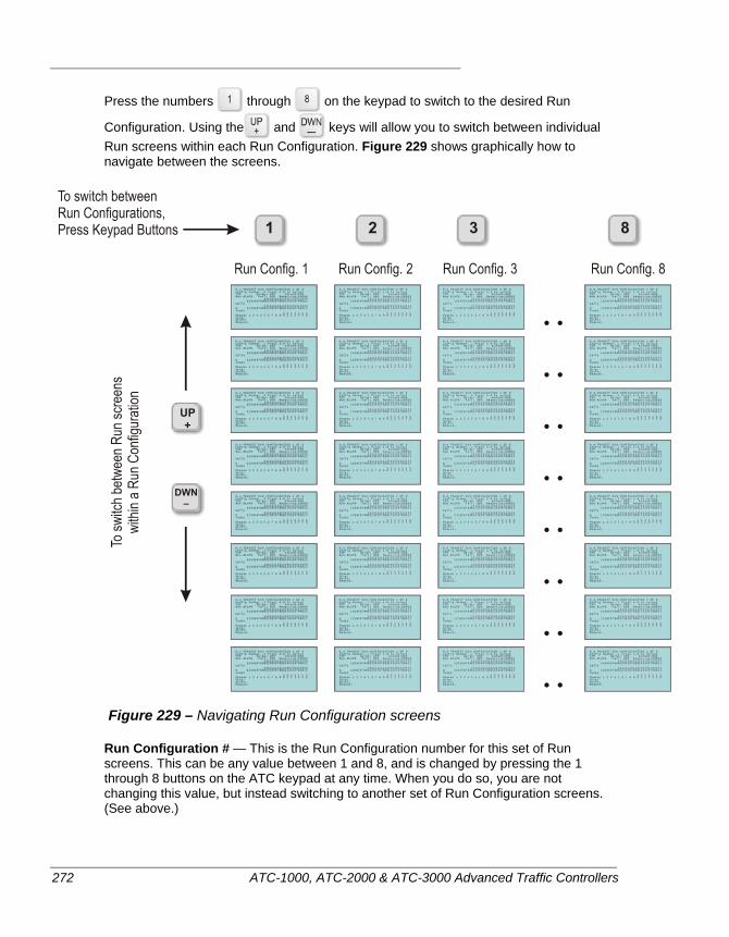
272 ATC-1000, ATC-2000 & ATC-3000 Advanced Traffic Controllers
Press the numbers through on the keypad to switch to the desired Run
Configuration. Using the and keys will allow you to switch between individual Run screens within each Run Configuration. Figure 229 shows graphically how to navigate between the screens.
Figure 229 – Navigating Run Configuration screens
Run Configuration # — This is the Run Configuration number for this set of Run screens. This can be any value between 1 and 8, and is changed by pressing the 1 through 8 buttons on the ATC keypad at any time. When you do so, you are not changing this value, but instead switching to another set of Run Configuration screens. (See above.)
TSP Screens and Parameters
ATC-1000, ATC-2000 & ATC-3000 Advanced Traffic Controllers 273
Run # — This indicates which of the eight runs within the Run Configuration you are currently viewing or editing. You can navigate between the Run screens by using the
and buttons.
Delay — This is a modification on the TSP input that feeds this run. When set, the TSP Run waits this number of seconds before processing the request. An example use could be that a bus has non-directional TSP indicator and crosses the street upstream in one direction of the intersection. You would not want that bus to trigger TSP activity in this intersection, so you could put a delay in to cover the period when the bus may be visible by this intersection’s TSP detector. The default value is 0.
Ext — (Extend) This is also a modification on the TSP input that feeds this run. If Extend is set, the input is artificially maintained ON for this number of seconds beyond the time it would normally turn OFF in each of the three input modes. (For a discussion of ‘Input Mode”, see page 268.) The default value is 0.
Note The Extend value on this screen is NOT the amount of time that the green is extended when the TSP Input is received. The actual extension time values for TSP operation are set on the TSP Split Table screens. (MM > 2.PROGRAMMING > 8.TRANSIT SIGNAL PRIORITY > 6.SPLIT TABLE)
Fail — This is a test on the TSP input. If the input stays ON for this number of seconds, the input is ignored, and no further inputs on this channel will be accepted until the ON signal goes away. This has a couple of purposes. It can take care of the case where a transit vehicle may be stopped near an intersection for repair, or for some other activity, and the TSP emitter on the vehicle remains on and visible to the intersection’s TSP detector. Or it can also handle the case where the detector or input line are faulty and keep the input ON in error. The default value is 0.
Reserve — (Reservice) Reservice time is the amount of time that the controller locks out all additional TSP Requests after a TSP Run has finished. (Actually, for reservice criteria, the test is actually the time since the TSP Request went away OR there is a Clearance Fail.) A value of 0 (zero) means that this reservice limit is deactivated, meaning a second TSP call will be accepted immediately after the first request. The value stored on this screen is the ‘Per Run’ reservice time. Note that there is also a reservice time value associated with the overall TSP Action Plan, known as the Master Reservice Time. Whichever value is greater (either the Master Reservice Time described on page 270, or the Reservice Time stored here in the individual Run) will be the active requirement within the intersection. Applies only if the TSP Request adjusts phase times.
Max Requests During Offset Corr — The maximum number of times a TSP Request can extend an already-extending phase (due to TSP Recovery), to prevent toggling TSP Requests from infinitely extending a phase.
Calls — This is the master list of phases or intervals that will be serviced by TSP actions whenever this TSP Input is activated and this TSP Run Configuration group is the selected group. When an ‘X’ is placed under one of these calls, the associated phase number, or interval if running in a Pre-timed pattern, will receive the calls to Green
274 ATC-1000, ATC-2000 & ATC-3000 Advanced Traffic Controllers
Extend. Green Extend is the default action of a TSP priority call. If you wish to apply the additional Q Jump function available below, the phases also need to be selected here in the Calls array. Use the YES button to place an ‘X’ and the NO button to remove an ‘X’.
Q Jumps — This array of values is used to enable and disable Queue jumping on the selected phases or intervals when a TSP input is received on this channel. Typically, this is an extra phase or interval that is only activated during TSP actions. For a Q Jump action to occur, an ‘X’ must be placed in that phase/interval, and the associated Call phase above must also be checked. Use the YES and NO buttons to control which Q Jump phases are checked.
Skip phases — Use the YES and NO buttons to places ‘X’s next to those phases that should be skipped over during the upcoming cycle as a result of this TSP input. If the same phase is called above in the Call array and also here in the Skip array, the Skip action will be ignored. In US DOT vernacular, this is known as the ‘Phase Skipping’ capability. This TSP method will not be used if the controller is currently operating in a Pre-timed pattern.
Shift phases — Use the YES and NO buttons to places ‘X’s next to those phases that will be shifted to the most favorable sequence position within the phase’s concurrency group, causing quicker transit vehicle service.
Example: Standard 8-phase dual ring sequence, TSP phase = 4/8, Shift phase = 4/8. If a TSP call occurs during 2/6, shifting causes 2/6 -> 4/8 -> 3/7 -> 2/6. If a TSP call occurs during 3/7, no shifting occurs because 4/8 are in the most favorable position.
Reduce phases — Use the YES and NO buttons to places ‘X’s next to those phases that should be split reduced. The normal way to use this is to have all of the phases that are not selected as Calls (above) be selected (‘X’) to allow them to be split reduced. In US DOT vernacular, this is known as the ‘Early Green’ capability. This TSP method will not be used if the controller is currently operating in a Pre-timed pattern. The Reduce flag shortens intermediate phase splits, thus causing an earlier TSP phase start than would be possible otherwise.
Reserve phases — This option allows a TSP-called Shift phase to run twice per cycle.
In the Shift Phases example above, if Reserve Phases = 4,8, a constant TSP Run Request activating during 2/6 and calling phases 4/8 causes cycling: 2/6 -> 4,8 -> 3/7 -> 4/8 (via Reserve) -> 1/5 -> 2/6.
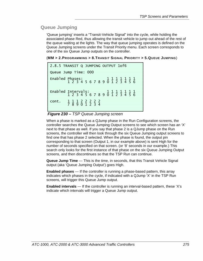
TSP Screens and Parameters
ATC-1000, ATC-2000 & ATC-3000 Advanced Traffic Controllers 275
Queue Jumping ‘Queue jumping’ inserts a “Transit-Vehicle Signal” into the cycle, while holding the associated phase Red, thus allowing the transit vehicle to jump out ahead of the rest of the queue waiting at the lights. The way that queue jumping operates is defined on the Queue Jumping screens under the Transit Priority menu. Each screen corresponds to one of the six Queue Jump outputs on the controller.
(MM > 2.PROGRAMMING > 8.TRANSIT SIGNAL PRIORITY > 5.QUEUE JUMPING)
2.8.5 TRANSIT Q JUMPING OUTPUT 1of6 Queue Jump Time: 000 Enabled Phases: 1 1 1 1 1 1 1 1 2 3 4 5 6 7 8 9 0 1 2 3 4 5 6 Enabled Intervals: 1 1 1 1 1 1 1 1 2 3 4 5 6 7 8 9 0 1 2 3 4 5 6 cont. 1 1 1 2 2 2 2 2 7 8 9 0 1 2 3 4
Figure 230 – TSP Queue Jumping screen When a phase is marked as a QJump phase in the Run Configuration screens, the controller searches the Queue Jumping Output screens to see which screen has an ‘X’ next to that phase as well. If you say that phase 2 is a QJump phase on the Run screens, the controller will then look through the six Queue Jumping output screens to find one that has phase 2 selected. When the phase is found, the output pin corresponding to that screen (Output 1, in our example above) is sent High for the number of seconds specified on that screen. (or ‘8’ seconds in our example.) This search only looks for the first instance of that phase on the six Queue Jumping Output screens, and then discontinues so that the TSP Run can continue.
Queue Jump Time — This is the time, in seconds, that this Transit Vehicle Signal output (aka ‘Queue Jumping Output’) goes High.
Enabled phases — If the controller is running a phase-based pattern, this array indicates which phases in the cycle, if indicated with a QJump ‘X’ in the TSP Run screens, will trigger this Queue Jump output.
Enabled intervals — If the controller is running an interval-based pattern, these ‘X’s indicate which intervals will trigger a Queue Jump output.
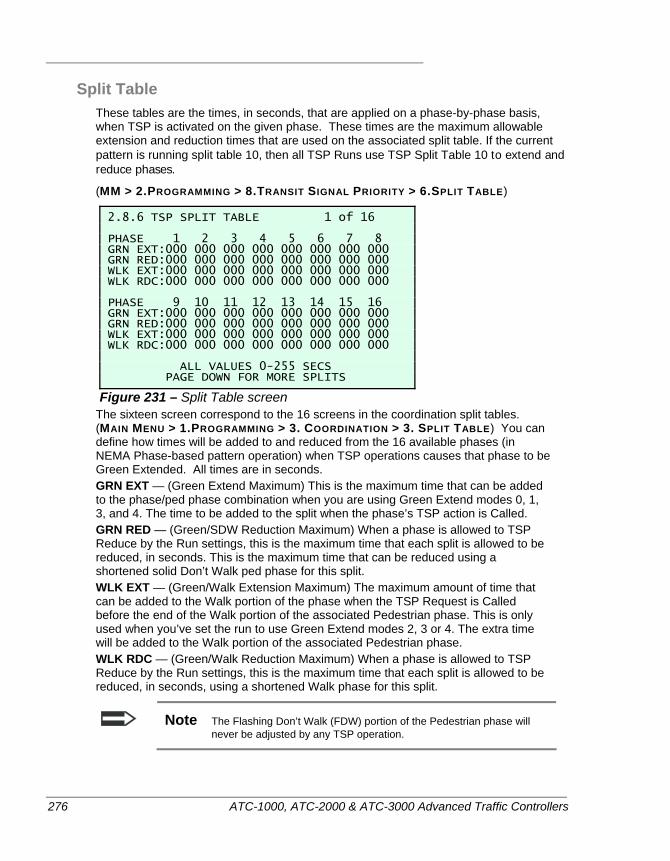
276 ATC-1000, ATC-2000 & ATC-3000 Advanced Traffic Controllers
Split Table These tables are the times, in seconds, that are applied on a phase-by-phase basis, when TSP is activated on the given phase. These times are the maximum allowable extension and reduction times that are used on the associated split table. If the current pattern is running split table 10, then all TSP Runs use TSP Split Table 10 to extend and reduce phases.
(MM > 2.PROGRAMMING > 8.TRANSIT SIGNAL PRIORITY > 6.SPLIT TABLE)
2.8.6 TSP SPLIT TABLE 1 of 16 PHASE 1 2 3 4 5 6 7 8 GRN EXT:000 000 000 000 000 000 000 000 GRN RED:000 000 000 000 000 000 000 000 WLK EXT:000 000 000 000 000 000 000 000 WLK RDC:000 000 000 000 000 000 000 000 PHASE 9 10 11 12 13 14 15 16 GRN EXT:000 000 000 000 000 000 000 000 GRN RED:000 000 000 000 000 000 000 000 WLK EXT:000 000 000 000 000 000 000 000 WLK RDC:000 000 000 000 000 000 000 000 ALL VALUES 0-255 SECS PAGE DOWN FOR MORE SPLITS
Figure 231 – Split Table screen The sixteen screen correspond to the 16 screens in the coordination split tables. (MAIN MENU > 1.PROGRAMMING > 3. COORDINATION > 3. SPLIT TABLE) You can define how times will be added to and reduced from the 16 available phases (in NEMA Phase-based pattern operation) when TSP operations causes that phase to be Green Extended. All times are in seconds. GRN EXT — (Green Extend Maximum) This is the maximum time that can be added to the phase/ped phase combination when you are using Green Extend modes 0, 1, 3, and 4. The time to be added to the split when the phase’s TSP action is Called. GRN RED — (Green/SDW Reduction Maximum) When a phase is allowed to TSP Reduce by the Run settings, this is the maximum time that each split is allowed to be reduced, in seconds. This is the maximum time that can be reduced using a shortened solid Don’t Walk ped phase for this split. WLK EXT — (Green/Walk Extension Maximum) The maximum amount of time that can be added to the Walk portion of the phase when the TSP Request is Called before the end of the Walk portion of the associated Pedestrian phase. This is only used when you’ve set the run to use Green Extend modes 2, 3 or 4. The extra time will be added to the Walk portion of the associated Pedestrian phase. WLK RDC — (Green/Walk Reduction Maximum) When a phase is allowed to TSP Reduce by the Run settings, this is the maximum time that each split is allowed to be reduced, in seconds, using a shortened Walk phase for this split.
Note The Flashing Don’t Walk (FDW) portion of the Pedestrian phase will never be adjusted by any TSP operation.
TSP Status Monitoring
ATC-1000, ATC-2000 & ATC-3000 Advanced Traffic Controllers 277
TSP STATUS MONITORING
There are three Status screens that can be used to monitor the current state of TSP operations:
The Time of Day Status screen always shows the current TSP Action Plan assignment. (MAIN MENU > 1. STATUS > 1. CONTROLLER > 3. TIME OF DAY)
The TSP Inputs Status screen shows the current TSP inputs, the status of each of the eight TSP Runs, the signal colors of all of the NEMA phases. (MAIN MENU > 1. STATUS > 1.CONTROLLER > 6.T.S.P > 1. INPUTS)
The TSP Outputs Status screen shows the TSP outputs, the Q Jump outputs, the default programmed splits, and the TSP adjusted splits. (MAIN MENU > 1. STATUS > 1.CONTROLLER > 6.T.S.P > 2. OUTPUTS)
TSP TROUBLESHOOTING
Details are provided to help with the initial setup of TSP operations, and also for troubleshooting ongoing operation, in “Troubleshooting Transit Signal Priority Operation” with the TSP materials starting on page 299.

278 ATC-1000, ATC-2000 & ATC-3000 Advanced Traffic Controllers
ATC-1000, ATC-2000 & ATC-3000 Advanced Traffic Controllers 279
Chapter 11 — Configuration and Maintenance
This chapter describes the Utilities configuration menu of an ATC controller, as well as several hardware tools and techniques to troubleshoot the operations of the unit. The following topics are discussed in detail in this chapter:
• Accessing the Utilities menus, on page 280
• Firmware diagnostics mode, on page 297
• Data Logging, on page 292
• System maintenance, on page 297
• General troubleshooting hints, on page 297
• TSP Configuration hints, on page 300
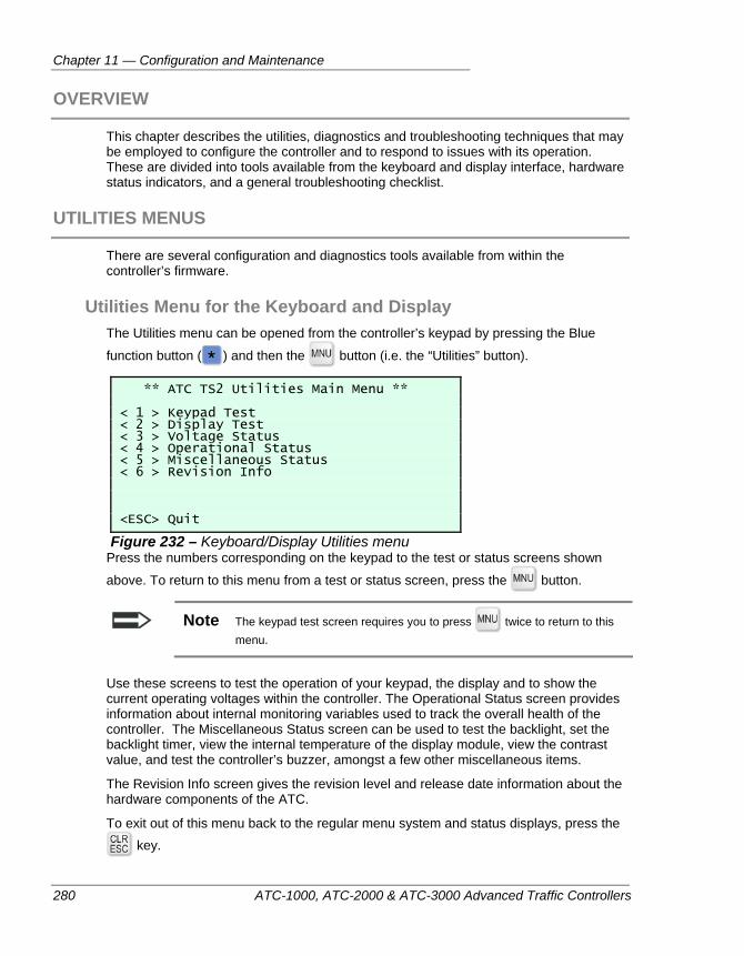
Chapter 11 — Configuration and Maintenance
280 ATC-1000, ATC-2000 & ATC-3000 Advanced Traffic Controllers
OVERVIEW
This chapter describes the utilities, diagnostics and troubleshooting techniques that may be employed to configure the controller and to respond to issues with its operation. These are divided into tools available from the keyboard and display interface, hardware status indicators, and a general troubleshooting checklist.
UTILITIES MENUS
There are several configuration and diagnostics tools available from within the controller’s firmware.
Utilities Menu for the Keyboard and Display The Utilities menu can be opened from the controller’s keypad by pressing the Blue
function button ( ) and then the button (i.e. the “Utilities” button).
** ATC TS2 Utilities Main Menu ** < 1 > Keypad Test < 2 > Display Test < 3 > Voltage Status < 4 > Operational Status < 5 > Miscellaneous Status < 6 > Revision Info <ESC> Quit
Figure 232 – Keyboard/Display Utilities menu Press the numbers corresponding on the keypad to the test or status screens shown
above. To return to this menu from a test or status screen, press the button.
Note The keypad test screen requires you to press twice to return to this menu.
Use these screens to test the operation of your keypad, the display and to show the current operating voltages within the controller. The Operational Status screen provides information about internal monitoring variables used to track the overall health of the controller. The Miscellaneous Status screen can be used to test the backlight, set the backlight timer, view the internal temperature of the display module, view the contrast value, and test the controller’s buzzer, amongst a few other miscellaneous items.
The Revision Info screen gives the revision level and release date information about the hardware components of the ATC.
To exit out of this menu back to the regular menu system and status displays, press the key.
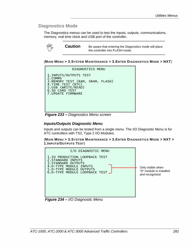
Utilities Menus
ATC-1000, ATC-2000 & ATC-3000 Advanced Traffic Controllers 281
Diagnostics Mode The Diagnostics menus can be used to test the inputs, outputs, communications, memory, real time clock and USB port of the controller.
Caution Be aware that entering the Diagnostics mode will place
the controller into FLASH mode.
(MAIN MENU > 3.SYSTEM MAINTENANCE > 3.ENTER DIAGNOSTICS MODE > NXT)
DIAGNOSTICS MENU 1.INPUTS/OUTPUTS TEST 2.COMMS 3.MEMORY TEST (RAM, SRAM, FLASH) 4.TIME TEST (RTC) 5.USB (WRITE/READ) 6.SD CARD TEST 7.UPDATE FIRMWARE
Figure 233 – Diagnostics Menu screen
Inputs/Outputs Diagnostic Menu Inputs and outputs can be tested from a single menu. The I/O Diagnostic Menu is for ATC controllers with TS2, Type 2 I/O Modules.
(MAIN MENU > 3.SYSTEM MAINTENANCE > 3.ENTER DIAGNOSTICS MODE > NXT > 1.INPUTS/OUTPUTS TEST)
I/O DIAGNOSTIC MENU 1.IO PRODUCTION LOOPBACK TEST 2.STANDARD INPUTS 3.STANDARD OUTPUTS 4.D-TYPE MODULE INPUTS 5.D-TYPE MODULE OUTPUTS 6.D-TYPE MODULE LOOPBACK TEST
Figure 234 – I/O Diagnostic Menu
Only visible when “D” module is installed and recognized
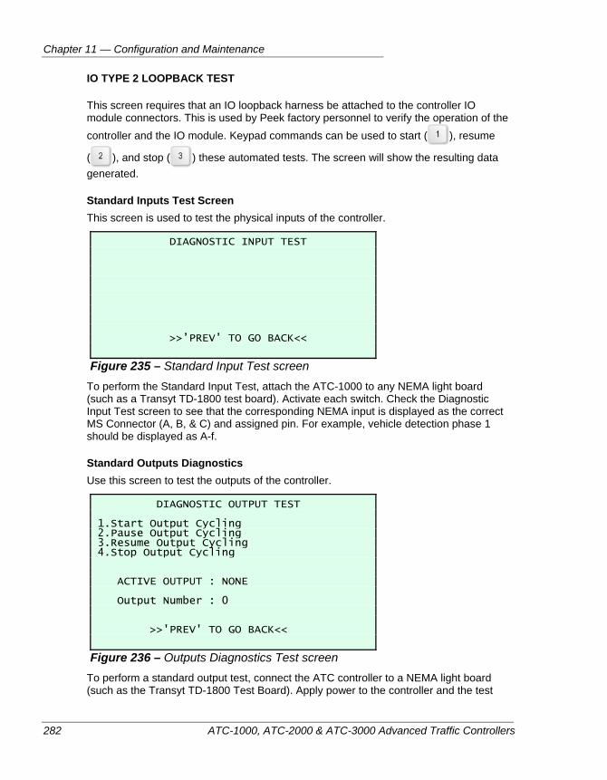
Chapter 11 — Configuration and Maintenance
282 ATC-1000, ATC-2000 & ATC-3000 Advanced Traffic Controllers
IO TYPE 2 LOOPBACK TEST
This screen requires that an IO loopback harness be attached to the controller IO module connectors. This is used by Peek factory personnel to verify the operation of the controller and the IO module. Keypad commands can be used to start ( ), resume
( ), and stop ( ) these automated tests. The screen will show the resulting data generated.
Standard Inputs Test Screen This screen is used to test the physical inputs of the controller.
DIAGNOSTIC INPUT TEST >>’PREV’ TO GO BACK<<
Figure 235 – Standard Input Test screen To perform the Standard Input Test, attach the ATC-1000 to any NEMA light board (such as a Transyt TD-1800 test board). Activate each switch. Check the Diagnostic Input Test screen to see that the corresponding NEMA input is displayed as the correct MS Connector (A, B, & C) and assigned pin. For example, vehicle detection phase 1 should be displayed as A-f.
Standard Outputs Diagnostics Use this screen to test the outputs of the controller.
DIAGNOSTIC OUTPUT TEST 1.Start Output Cycling 2.Pause Output Cycling 3.Resume Output Cycling 4.Stop Output Cycling ACTIVE OUTPUT : NONE Output Number : 0 >>'PREV' TO GO BACK<<
Figure 236 – Outputs Diagnostics Test screen To perform a standard output test, connect the ATC controller to a NEMA light board (such as the Transyt TD-1800 Test Board). Apply power to the controller and the test
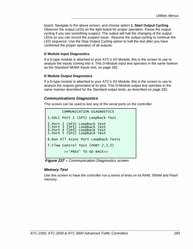
Utilities Menus
ATC-1000, ATC-2000 & ATC-3000 Advanced Traffic Controllers 283
board. Navigate to the above screen, and choose option 1. Start Output Cycling. Observer the output LEDs on the light board for proper operation. Pause the output cycling if you see something suspect. The output will halt the changing of the output LEDs so you can record the suspect issue. Resume the output cycling to continue the LED sequence. Use the Stop Output Cycling option to halt the test after you have confirmed the proper operation of all outputs.
D Module Input Diagnostics If a D-type module is attached to your ATC’s I/O Module, this is the screen to use to analyze the inputs coming into it. This D-Module input test operates in the same fashion as the Standard NEMA Inputs test, on page 282.
D Module Output Diagnostics If a D-type module is attached to your ATC’s I/O Module, this is the screen to use to analyze the outputs generated at its pins. This D-Module output test operates in the same manner described for the Standard output tests, as described on page 282.
Communications Diagnostics This screen can be used to test any of the serial ports on the controller.
COMMUNICATION DIAGNOSTICS 1.SDLC Port 1 (SP5) Loopback Test 2.Port 2 (SP3) Loopback Test 3.Port 3 (SP1) Loopback Test 4.Port 4 (SP4) Loopback Test 5.Port 5 (SP2) Loopback Test 6.Run All Async Port Loopback Tests 7.Flow Control Test (PORT 2,3,5) >>'PREV' TO GO BACK<<
Figure 237 – Communication Diagnostics screen
Memory Test Use this screen to have the controller run a series of tests on its RAM, SRAM and Flash memory.
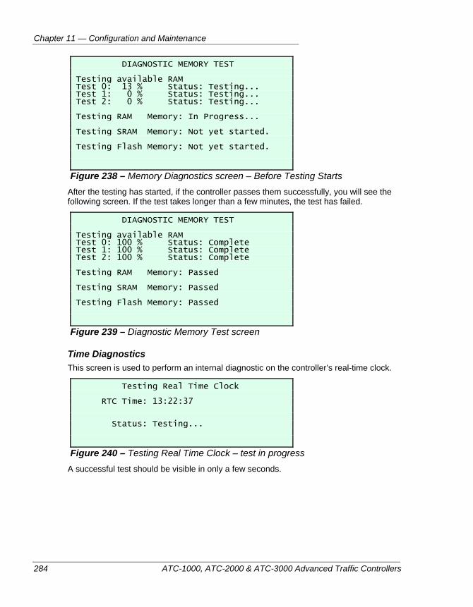
Chapter 11 — Configuration and Maintenance
284 ATC-1000, ATC-2000 & ATC-3000 Advanced Traffic Controllers
DIAGNOSTIC MEMORY TEST Testing available RAM Test 0: 13 % Status: Testing... Test 1: 0 % Status: Testing... Test 2: 0 % Status: Testing... Testing RAM Memory: In Progress... Testing SRAM Memory: Not yet started. Testing Flash Memory: Not yet started.
Figure 238 – Memory Diagnostics screen – Before Testing Starts After the testing has started, if the controller passes them successfully, you will see the following screen. If the test takes longer than a few minutes, the test has failed.
DIAGNOSTIC MEMORY TEST Testing available RAM Test 0: 100 % Status: Complete Test 1: 100 % Status: Complete Test 2: 100 % Status: Complete Testing RAM Memory: Passed Testing SRAM Memory: Passed Testing Flash Memory: Passed
Figure 239 – Diagnostic Memory Test screen
Time Diagnostics This screen is used to perform an internal diagnostic on the controller’s real-time clock.
Testing Real Time Clock RTC Time: 13:22:37 Status: Testing...
Figure 240 – Testing Real Time Clock – test in progress A successful test should be visible in only a few seconds.
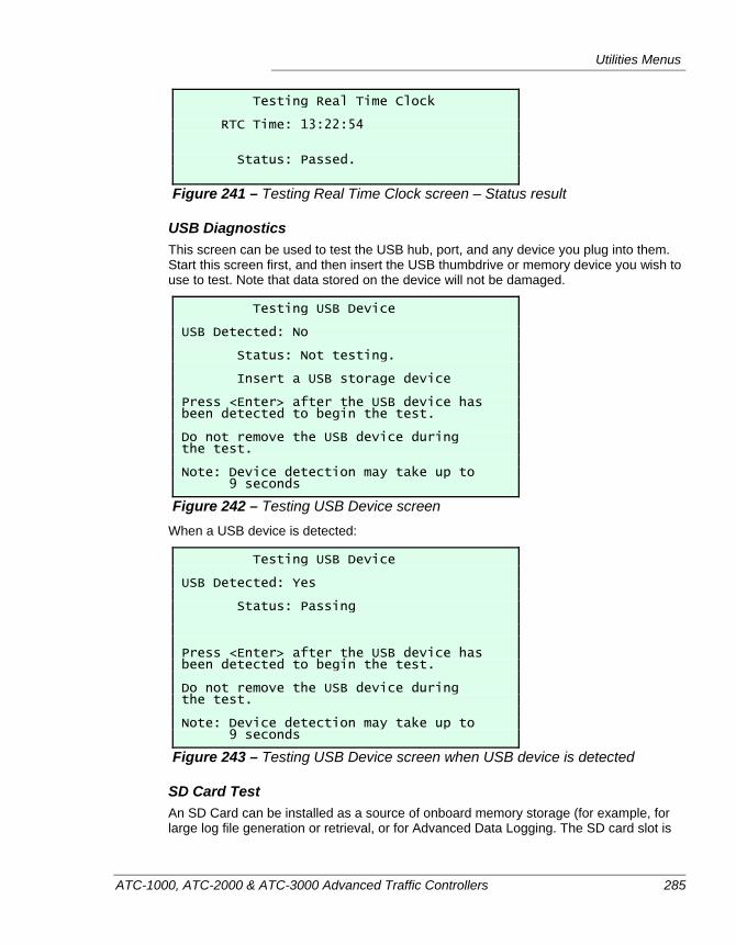
Utilities Menus
ATC-1000, ATC-2000 & ATC-3000 Advanced Traffic Controllers 285
Testing Real Time Clock RTC Time: 13:22:54 Status: Passed.
Figure 241 – Testing Real Time Clock screen – Status result
USB Diagnostics This screen can be used to test the USB hub, port, and any device you plug into them. Start this screen first, and then insert the USB thumbdrive or memory device you wish to use to test. Note that data stored on the device will not be damaged.
Testing USB Device USB Detected: No Status: Not testing. Insert a USB storage device Press <Enter> after the USB device has been detected to begin the test. Do not remove the USB device during the test. Note: Device detection may take up to 9 seconds
Figure 242 – Testing USB Device screen When a USB device is detected:
Testing USB Device USB Detected: Yes Status: Passing Press <Enter> after the USB device has been detected to begin the test. Do not remove the USB device during the test. Note: Device detection may take up to 9 seconds
Figure 243 – Testing USB Device screen when USB device is detected
SD Card Test An SD Card can be installed as a source of onboard memory storage (for example, for large log file generation or retrieval, or for Advanced Data Logging. The SD card slot is
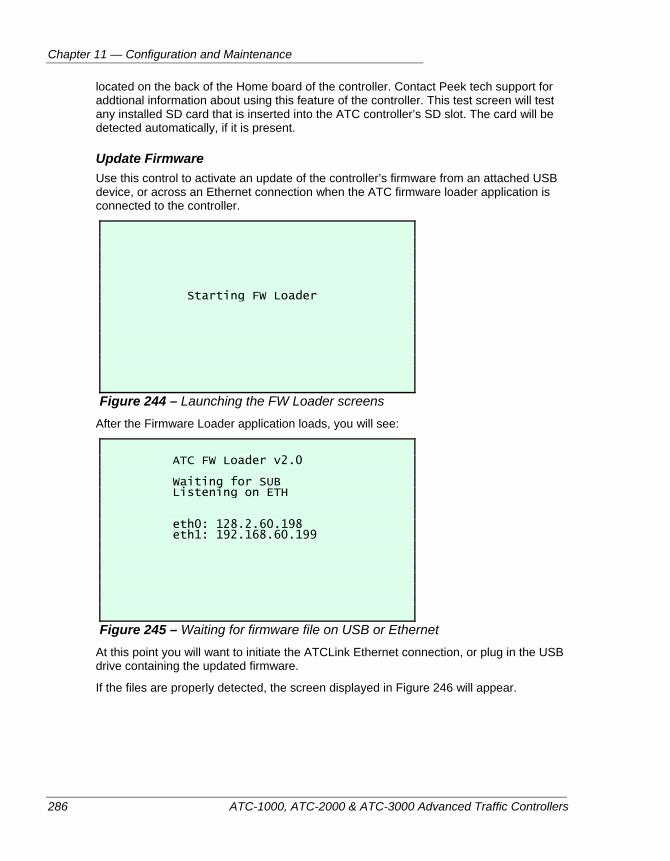
Chapter 11 — Configuration and Maintenance
286 ATC-1000, ATC-2000 & ATC-3000 Advanced Traffic Controllers
located on the back of the Home board of the controller. Contact Peek tech support for addtional information about using this feature of the controller. This test screen will test any installed SD card that is inserted into the ATC controller’s SD slot. The card will be detected automatically, if it is present.
Update Firmware Use this control to activate an update of the controller’s firmware from an attached USB device, or across an Ethernet connection when the ATC firmware loader application is connected to the controller.
Starting FW Loader
Figure 244 – Launching the FW Loader screens After the Firmware Loader application loads, you will see:
ATC FW Loader v2.0 Waiting for SUB Listening on ETH eth0: 128.2.60.198 eth1: 192.168.60.199
Figure 245 – Waiting for firmware file on USB or Ethernet At this point you will want to initiate the ATCLink Ethernet connection, or plug in the USB drive containing the updated firmware.
If the files are properly detected, the screen displayed in Figure 246 will appear.
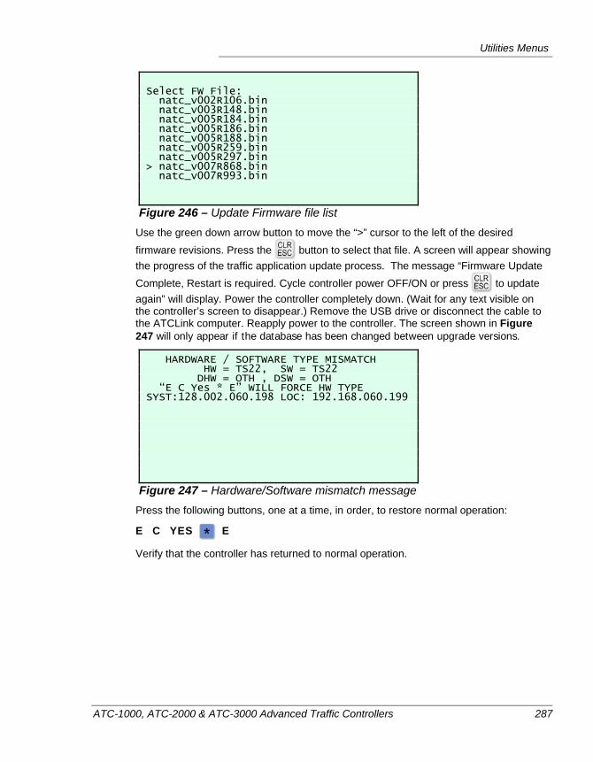
Utilities Menus
ATC-1000, ATC-2000 & ATC-3000 Advanced Traffic Controllers 287
Select FW File: natc_v002R106.bin natc_v003R148.bin natc_v005R184.bin natc_v005R186.bin natc_v005R188.bin natc_v005R259.bin natc_v005R297.bin > natc_v007R868.bin natc_v007R993.bin
Figure 246 – Update Firmware file list Use the green down arrow button to move the “>” cursor to the left of the desired firmware revisions. Press the button to select that file. A screen will appear showing the progress of the traffic application update process. The message “Firmware Update Complete, Restart is required. Cycle controller power OFF/ON or press to update again” will display. Power the controller completely down. (Wait for any text visible on the controller’s screen to disappear.) Remove the USB drive or disconnect the cable to the ATCLink computer. Reapply power to the controller. The screen shown in Figure 247 will only appear if the database has been changed between upgrade versions.
HARDWARE / SOFTWARE TYPE MISMATCH HW = TS22, SW = TS22 DHW = OTH , DSW = OTH “E C Yes * E” WILL FORCE HW TYPE SYST:128.002.060.198 LOC: 192.168.060.199
Figure 247 – Hardware/Software mismatch message Press the following buttons, one at a time, in order, to restore normal operation:
E C YES E
Verify that the controller has returned to normal operation.
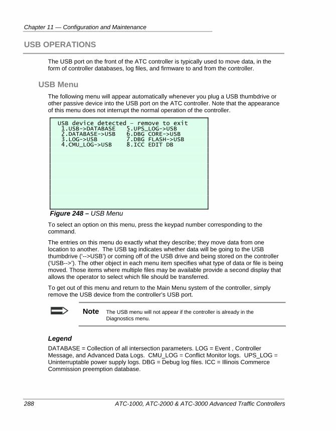
Chapter 11 — Configuration and Maintenance
288 ATC-1000, ATC-2000 & ATC-3000 Advanced Traffic Controllers
USB OPERATIONS
The USB port on the front of the ATC controller is typically used to move data, in the form of controller databases, log files, and firmware to and from the controller.
USB Menu The following menu will appear automatically whenever you plug a USB thumbdrive or other passive device into the USB port on the ATC controller. Note that the appearance of this menu does not interrupt the normal operation of the controller.
USB device detected – remove to exit 1.USB->DATABASE 5.UPS_LOG->USB 2.DATABASE->USB 6.DBG CORE->USB 3.LOG->USB 7.DBG FLASH->USB 4.CMU_LOG->USB 8.ICC EDIT DB
Figure 248 – USB Menu To select an option on this menu, press the keypad number corresponding to the command.
The entries on this menu do exactly what they describe; they move data from one location to another. The USB tag indicates whether data will be going to the USB thumbdrive (‘-->USB’) or coming off of the USB drive and being stored on the controller (‘USB-->’). The other object in each menu item specifies what type of data or file is being moved. Those items where multiple files may be available provide a second display that allows the operator to select which file should be transferred.
To get out of this menu and return to the Main Menu system of the controller, simply remove the USB device from the controller’s USB port.
Note The USB menu will not appear if the controller is already in the Diagnostics menu.
Legend DATABASE = Collection of all intersection parameters. LOG = Event , Controller Message, and Advanced Data Logs. CMU_LOG = Conflict Monitor logs. UPS_LOG = Uninterruptable power supply logs. DBG = Debug log files. ICC = Illinois Commerce Commission preemption database.
USB Operations
ATC-1000, ATC-2000 & ATC-3000 Advanced Traffic Controllers 289
Moving Databases Using a USB Drive The controller database, or the set of all operating parameters stored in the controller, can be moved to a USB thumbdrive so that it can be copied from controller to controller, or to be retrieved by a PC-based application such as ATCLink or IQ Central.
To move a database from a USB drive to the Controller 1. If the USB device has not been formatted previously to work with Peek ATC
controllers, use ATCLink to format the USB device.
2. Place a copy of the database you want to use on the controller onto the USB drive. This can be done either by writing it there from ATCLink, storing it on the USB device out of IQ Central, or copying the database out of another controller onto the USB device.
3. Plug the USB drive containing the database into the controller to be updated.
4. When the USB Menu appears, press the key on the keypad to select the USB->DATABASE command.
5. The controller will ask for verification: “Download astcFFFF ? ENT=Y ESC=N” The astcFFFF is the standard filename for a complete ATC controller database. If you agree that you want to overwrite all of the settings currently stored in your
controller, press the key. If you realize that you do not want to do this, press
the button to exit out of the copy process without overwriting the current database.
6. If you press , the file will be copied into the controller and decompressed into memory. Note that you need to restart the controller for the new settings to take effect.
7. Next, the controller will ask if you wish to “Download the IO Map?” Again, press
the button if you do want to overwrite the current I/O output mapping data to
the controller, or press if you do NOT want to overwrite these settings.
8. Finally, the controller will ask if you wish to copy over the UPS objects. Press
to copy those items into the controller. Press if you wish to cancel that process.
9. You will be returned to the USB menu. Remove the USB drive from the port. Note that you need to restart the controller for the new settings to take effect Verify that the new database values are in place and functioning.
To store the controller database on a USB drive 1. If the USB device has not been formatted previously to work with a Peek ATC
controllers, use ATCLink to format the USB device.
Chapter 11 — Configuration and Maintenance
290 ATC-1000, ATC-2000 & ATC-3000 Advanced Traffic Controllers
2. Plug the USB drive into the controller.
3. When the USB Menu appears, press the key to select the DATABASE-->USB command.
4. If the current database version is not already present on the drive, the file will be sent immediately.
5. If a database is already stored on the drive, you will be asked if you want to
overwrite it. Press the button to overwrite the database file currently stored
on the USB thumbdrive, or press to cancel out of the process.
6. The controller will report the action and then return you to the USB menu. Remove the thumbdrive from the USB port.
Moving Logs Using a USB Drive There are three types of logs stored on an ATC controller that can be accessed by the USB drive: Event logs (or just ‘LOG”), CMU logs, and UPS logs. You will have the option to choose which one to store on the USB thumbdrive in step 3 below.
1. If the USB device has not been formatted previously to work with Peek ATC controllers, use ATCLink to format the USB device.
2. Plug the USB drive into the controller.
3. When the USB Menu appears, decide which log file you would like to retrieve. You can choose one or more of these options at this stage:
Press the key to move the event log files to the USB drive.
Press the key to move the conflict monitor log files to the USB drive.
press the key to move the UPS log files to the USB drive.
4. The controller will report the data transfer action and then return you to the USB menu. Remove the thumbdrive from the USB port.
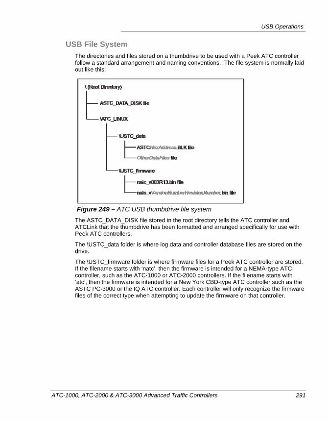
USB Operations
ATC-1000, ATC-2000 & ATC-3000 Advanced Traffic Controllers 291
USB File System The directories and files stored on a thumbdrive to be used with a Peek ATC controller follow a standard arrangement and naming conventions. The file system is normally laid out like this:
Figure 249 – ATC USB thumbdrive file system
The ASTC_DATA_DISK file stored in the root directory tells the ATC controller and ATCLink that the thumbdrive has been formatted and arranged specifically for use with Peek ATC controllers.
The \USTC_data folder is where log data and controller database files are stored on the drive.
The \USTC_firmware folder is where firmware files for a Peek ATC controller are stored. If the filename starts with ‘natc’, then the firmware is intended for a NEMA-type ATC controller, such as the ATC-1000 or ATC-2000 controllers. If the filename starts with ‘atc’, then the firmware is intended for a New York CBD-type ATC controller such as the ASTC PC-3000 or the IQ ATC controller. Each controller will only recognize the firmware files of the correct type when attempting to update the firmware on that controller.
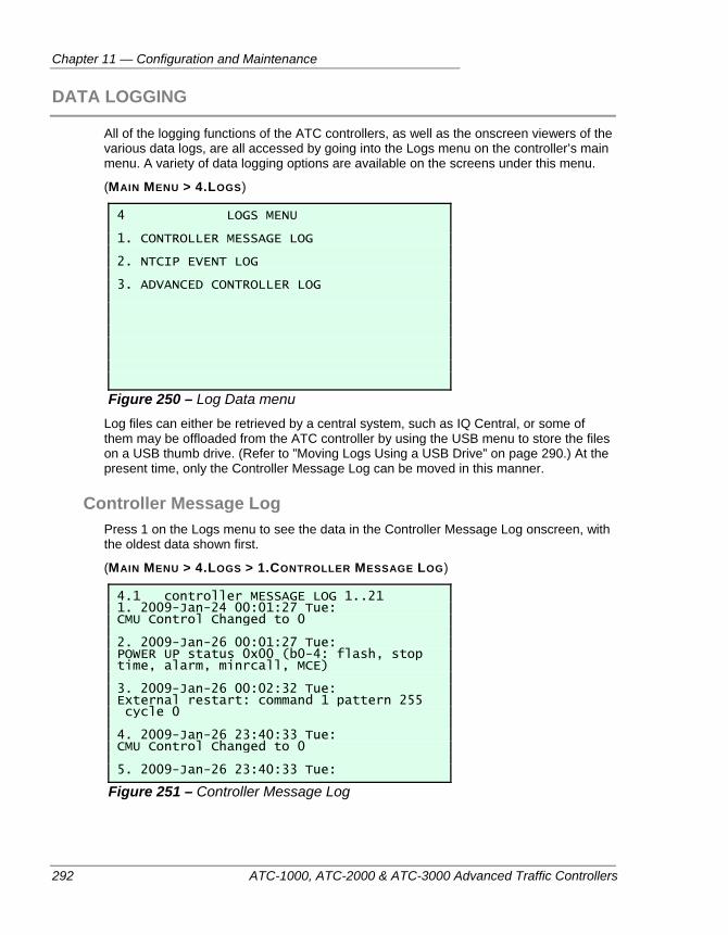
Chapter 11 — Configuration and Maintenance
292 ATC-1000, ATC-2000 & ATC-3000 Advanced Traffic Controllers
DATA LOGGING
All of the logging functions of the ATC controllers, as well as the onscreen viewers of the various data logs, are all accessed by going into the Logs menu on the controller’s main menu. A variety of data logging options are available on the screens under this menu.
(MAIN MENU > 4.LOGS)
4 LOGS MENU 1. CONTROLLER MESSAGE LOG 2. NTCIP EVENT LOG 3. ADVANCED CONTROLLER LOG
Figure 250 – Log Data menu Log files can either be retrieved by a central system, such as IQ Central, or some of them may be offloaded from the ATC controller by using the USB menu to store the files on a USB thumb drive. (Refer to ”Moving Logs Using a USB Drive” on page 290.) At the present time, only the Controller Message Log can be moved in this manner.
Controller Message Log Press 1 on the Logs menu to see the data in the Controller Message Log onscreen, with the oldest data shown first.
(MAIN MENU > 4.LOGS > 1.CONTROLLER MESSAGE LOG)
4.1 controller MESSAGE LOG 1..21 1. 2009-Jan-24 00:01:27 Tue: CMU Control Changed to 0 2. 2009-Jan-26 00:01:27 Tue: POWER UP status 0x00 (b0-4: flash, stop time, alarm, minrcall, MCE) 3. 2009-Jan-26 00:02:32 Tue: External restart: command 1 pattern 255 cycle 0 4. 2009-Jan-26 23:40:33 Tue: CMU Control Changed to 0 5. 2009-Jan-26 23:40:33 Tue:
Figure 251 – Controller Message Log
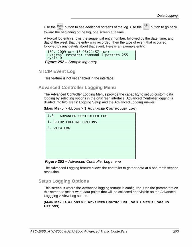
Data Logging
ATC-1000, ATC-2000 & ATC-3000 Advanced Traffic Controllers 293
Use the button to see additional screens of the log. Use the button to go back toward the beginning of the log, one screen at a time.
A typical log entry shows the sequential entry number, followed by the date, time, and day of the week that the entry was recorded, then the type of event that occurred, followed by any details about that event. Here is an example entry: 130. 2009-Oct-13 06:21:57 Tue: External restart: command 1 pattern 255 cycle 0
Figure 252 – Sample log entry
NTCIP Event Log This feature is not yet enabled in the interface.
Advanced Controller Logging Menu The Advanced Controller Logging Menus provide the capability to set up custom data logging by selecting options in the onscreen interface. Advanced Controller logging is divided into two areas: Logging Setup and the Advanced Logging Viewer.
(MAIN MENU > 4.LOGS > 3.ADVANCED CONTROLLER LOG)
4.3 ADVANCED CONTROLLER LOG 1. SETUP LOGGING OPTIONS 2. VIEW LOG
Figure 253 – Advanced Controller Log menu The Advanced Logging feature allows the controller to gather data at a one-tenth second resolution.
Setup Logging Options This screen is where the Advanced logging feature is configured. Use the parameters on this screen to select what data points that will be collected and visible on the Advanced Loggging > View Log screen.
(MAIN MENU > 4.LOGS > 3.ADVANCED CONTROLLER LOG > 1.SETUP LOGGING OPTIONS)
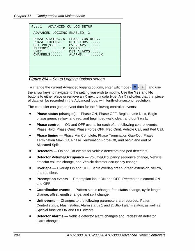
Chapter 11 — Configuration and Maintenance
294 ATC-1000, ATC-2000 & ATC-3000 Advanced Traffic Controllers
4.3.1 ADVANCED CU LOG SETUP ADVANCED LOGGING ENABLED..X PHASE STATUS..X PHASE CONTROL.. PHASE TIMING.. DETECTORS...... DET VOL/OCC .. OVERLAPS....... PREEMPT.......X COORD.......... UNIT.......... DET ALARMS..... CHANNELS...... ALARMS.........X
Figure 254 – Setup Logging Options screen
To change the current Advanced logging options, enter Edit mode ( - ) and use the arrow keys to navigate to the setting you wish to modify. Use the YES and NO buttons to either place or remove an X next to a data type. An X indicates that that piece of data will be recorded in the Advanced logs, with tenth-of-a-second resolution.
The controller can gather event data for the following controller events:
Phase status (changes) — Phase ON, Phase OFF, Begin phase Next, Begin phase green, yellow, and red, and begin ped walk, clear, and don’t walk.
Phase control — ON and OFF events for each of the following control events: Phase Hold, Phase Omit, Phase Force OFF, Ped Omit, Vehicle Call, and Ped Call.
Phase timing — Phase Min Complete, Phase Termination Gap-Out, Phase Termination Max-Out, Phase Termination Force-Off, and begin and end of Allocated Split.
Detectors — On and Off events for vehicle detectors and ped detectors
Detector Volume/Occupancy — Volume/Occupancy sequence change, Vehicle detector volume change, and Vehicle detector occupancy change.
Overlaps — Overlap On and OFF, Begin overlap green, green extension, yellow, and red clear.
Preemption events — Preemption input ON and OFF, Preemptor in control ON and OFF.
Coordination events — Pattern status change, free status change, cycle length change, offset length change, and split change.
Unit events — Changes to the following parameters are recorded: Pattern, Control status, Flash status, Alarm status 1 and 2, Short alarm status, as well as Special function ON and OFF events
Detector Alarms — Vehicle detector alarm changes and Pedestrian detector alarm changes
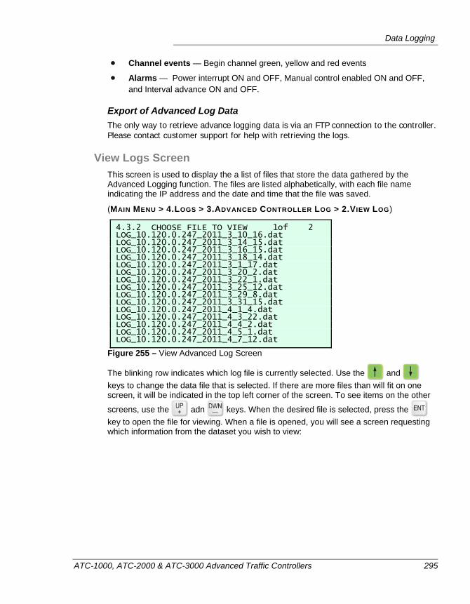
Data Logging
ATC-1000, ATC-2000 & ATC-3000 Advanced Traffic Controllers 295
Channel events — Begin channel green, yellow and red events
Alarms — Power interrupt ON and OFF, Manual control enabled ON and OFF, and Interval advance ON and OFF.
Export of Advanced Log Data The only way to retrieve advance logging data is via an FTP connection to the controller. Please contact customer support for help with retrieving the logs.
View Logs Screen This screen is used to display the a list of files that store the data gathered by the Advanced Logging function. The files are listed alphabetically, with each file name indicating the IP address and the date and time that the file was saved.
(MAIN MENU > 4.LOGS > 3.ADVANCED CONTROLLER LOG > 2.VIEW LOG)
4.3.2 CHOOSE FILE TO VIEW 1of 2 LOG_10.120.0.247_2011_3_10_16.dat LOG_10.120.0.247_2011_3_14_15.dat LOG_10.120.0.247_2011_3_16_15.dat LOG_10.120.0.247_2011_3_18_14.dat LOG_10.120.0.247_2011_3_1_17.dat LOG_10.120.0.247_2011_3_20_2.dat LOG_10.120.0.247_2011_3_22_1.dat LOG_10.120.0.247_2011_3_25_12.dat LOG_10.120.0.247_2011_3_29_8.dat LOG_10.120.0.247_2011_3_31_15.dat LOG_10.120.0.247_2011_4_1_4.dat LOG_10.120.0.247_2011_4_3_22.dat LOG_10.120.0.247_2011_4_4_2.dat LOG_10.120.0.247_2011_4_5_1.dat LOG_10.120.0.247_2011_4_7_12.dat
Figure 255 – View Advanced Log Screen
The blinking row indicates which log file is currently selected. Use the and keys to change the data file that is selected. If there are more files than will fit on one screen, it will be indicated in the top left corner of the screen. To see items on the other
screens, use the adn keys. When the desired file is selected, press the key to open the file for viewing. When a file is opened, you will see a screen requesting which information from the dataset you wish to view:
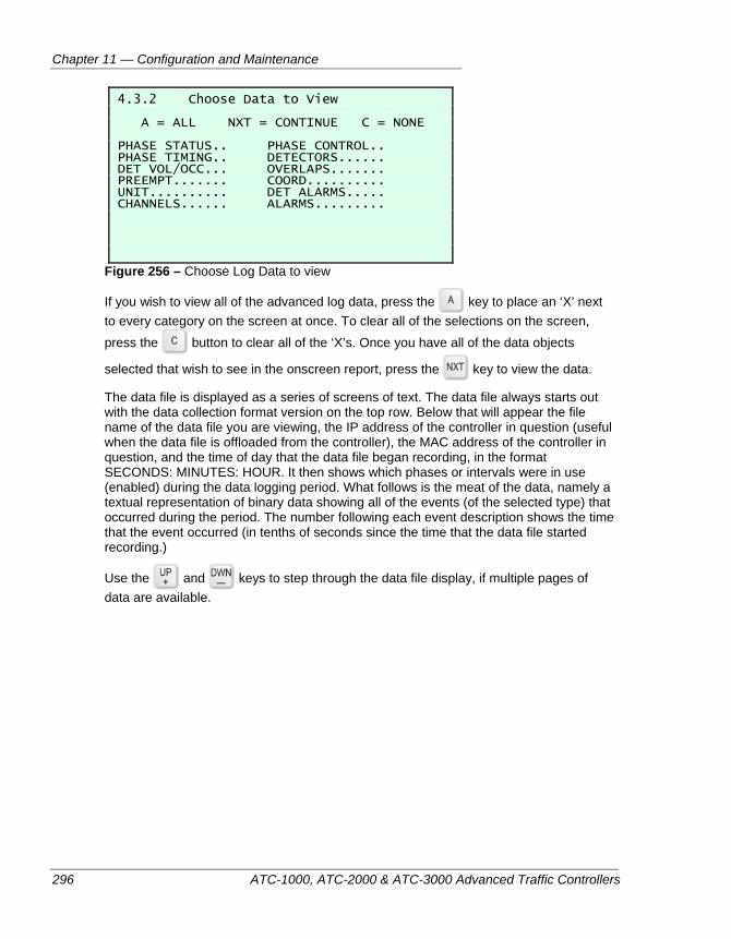
Chapter 11 — Configuration and Maintenance
296 ATC-1000, ATC-2000 & ATC-3000 Advanced Traffic Controllers
4.3.2 Choose Data to View A = ALL NXT = CONTINUE C = NONE PHASE STATUS.. PHASE CONTROL.. PHASE TIMING.. DETECTORS...... DET VOL/OCC... OVERLAPS....... PREEMPT....... COORD.......... UNIT.......... DET ALARMS..... CHANNELS...... ALARMS.........
Figure 256 – Choose Log Data to view
If you wish to view all of the advanced log data, press the key to place an ‘X’ next to every category on the screen at once. To clear all of the selections on the screen, press the button to clear all of the ‘X’s. Once you have all of the data objects
selected that wish to see in the onscreen report, press the key to view the data.
The data file is displayed as a series of screens of text. The data file always starts out with the data collection format version on the top row. Below that will appear the file name of the data file you are viewing, the IP address of the controller in question (useful when the data file is offloaded from the controller), the MAC address of the controller in question, and the time of day that the data file began recording, in the format SECONDS: MINUTES: HOUR. It then shows which phases or intervals were in use (enabled) during the data logging period. What follows is the meat of the data, namely a textual representation of binary data showing all of the events (of the selected type) that occurred during the period. The number following each event description shows the time that the event occurred (in tenths of seconds since the time that the data file started recording.)
Use the and keys to step through the data file display, if multiple pages of data are available.
System Maintenance
ATC-1000, ATC-2000 & ATC-3000 Advanced Traffic Controllers 297
SYSTEM MAINTENANCE
Preventive Maintenance and Calibration The ATC controllers are designed to require minimal maintenance; however, certain simple steps should be taken to ensure proper operation. It is a good idea to periodically check the unit’s wiring, terminals, and connectors for signs of breakage and wear. Replace, if necessary. Vacuuming dust out of the unit and cleaning the front panel is a valuable step in maintaining good air circulation.
The controller should also be checked after it has been installed for six months, and then at least annually thereafter. Once the initial check is performed, a regular interval for preventive maintenance should be established based on the install and environmental conditions. During such a maintenance visit, the following procedures should be performed:
Check all wiring connections for tightness, corrosion, damaged insulation, etc.
Check all mounting hardware for proper tightness.
It is also recommended that the controller’s software be updated with the latest revisions, when updates are warranted. This will allow more efficient and trouble-free operation. Contact your Peek Traffic support representative to find out if updated firmware is available.
Diagnosing Controller Operation
Heartbeat LED A 3mm RED LED is located on the front panel just above and to the right of the USB port. This will flash about twice per second to indicate that the controller’s microprocessor is functioning. If it is lit continuously or continuously dark, this indicates that the controller CPU has stalled.
PC Communications The controller must be powered up and in its normal operating mode in order to communicate with a PC. When having problems establishing communications, check the LEDs above the port to see if communications are occurring. If none are, or no connection can be established, be sure the controller’s port settings (baud rate, bit length, etc.) are set correctly in the controller’s Main Menu > 2.Programming > 1.Unit Configuration > 5.Comms and I/O Setup menu, and make sure they match the settings of the computer’s COM port to the setings of PC application being run (i.e. ATCLink, HyperTerminal, IQ Central, TransSuite, etc.)
TROUBLESHOOTING
When a failure occurs during normal operation, after isolating the problem, most problems can be corrected using a screwdriver, a multimeter and/or simply replacing the
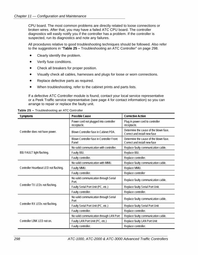
Chapter 11 — Configuration and Maintenance
298 ATC-1000, ATC-2000 & ATC-3000 Advanced Traffic Controllers
CPU board. The most common problems are directly related to loose connections or broken wires. After that, you may have a failed ATC CPU board. The controller diagnostics will easily notify you if the controller has a problem. If the controller is suspected, run its diagnostics and note any failures.
All procedures relative to good troubleshooting techniques should be followed. Also refer to the suggestions in “Table 25 – Troubleshooting an ATC Controller” on page 298.
Clearly identify the problem.
Verify fuse conditions.
Check all breakers for proper position.
Visually check all cables, harnesses and plugs for loose or worn connections.
Replace defective parts as required.
When troubleshooting, refer to the cabinet prints and parts lists.
If a defective ATC Controller module is found, contact your local service representative or a Peek Traffic service representative (see page 4 for contact information) so you can arrange to repair or replace the faulty unit.
Table 25 – Troubleshooting an ATC Controller
Symptoms Possible Cause Corrective Action Power cord not plugged into controller receptacle.
Plug in power cord to controller receptacle.
Blown Controller fuse in Cabinet PDA. Determine the cause of the blown fuse. Correct and install new fuse Controller does not have power.
Blown Controller fuse in Controller Front Panel
Determine the cause of the blown fuse. Correct and install new fuse
No valid communication with controller. Replace faulty communication cable. Faulty BIU. Replace BIU. BIU FAULT light flashing. Faulty controller. Replace controller. No valid communication with MMU. Replace faulty communication cable. Faulty MMU. Replace MMU. Controller Heartbeat LED not flashing. Faulty controller. Replace controller No valid communication through Serial Port. Replace faulty communication cable.
Faulty Serial Port Unit (PC, etc.) Replace faulty Serial Port Unit. Controller TX LEDs not flashing.
Faulty controller. Replace controller. No valid communication through Serial Port Replace faulty communication cable.
Faulty Serial Port Unit (PC, etc.) Replace faulty Serial Port Unit Controller RX LEDs not flashing.
Faulty controller. Replace controller. No valid communication through LAN Port Replace faulty communication cable. Faulty LAN Port Unit (PC, etc.) Replace faulty LAN Port Unit Controller LINK LED not on. Faulty controller. Replace controller.
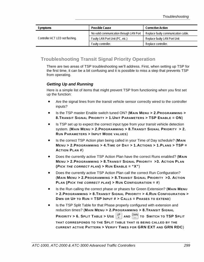
Troubleshooting
ATC-1000, ATC-2000 & ATC-3000 Advanced Traffic Controllers 299
Symptoms Possible Cause Corrective Action No valid communication through LAN Port Replace faulty communication cable. Faulty LAN Port Unit (PC, etc.) Replace faulty LAN Port Unit Controller ACT LED not flashing.
Faulty controller. Replace controller.
Troubleshooting Transit Signal Priority Operation There are two areas of TSP troubleshooting we’ll address. First, when setting up TSP for the first time, it can be a bit confusing and it is possible to miss a step that prevents TSP from operating.
Getting Up and Running Here is a simple list of items that might prevent TSP from functioning when you first set up the function:
Are the signal lines from the transit vehicle sensor correctly wired to the controller inputs?
Is the TSP master Enable switch tuned ON? (MAIN MENU > 2.PROGRAMMING > 8.TRANSIT SIGNAL PRIORITY > 1.UNIT PARAMETERS > TSP ENABLE = ON)
Is TSP set up to expect the correct input type from your transit vehicle detection system. (MAIN MENU > 2.PROGRAMMING > 8.TRANSIT SIGNAL PRIORITY > 2. RUN PARAMETERS > INPUT MODE VALUES)
Is the correct TSP Action plan being called in your Time of Day schedule? (MAIN MENU > 2.PROGRAMMING > 4.TIME OF DAY > 1.ACTIONS > 1.PLANS > TSP = ACTION PLAN #)
Does the currently active TSP Action Plan have the correct Runs enabled? (MAIN MENU > 2.PROGRAMMING > 8.TRANSIT SIGNAL PRIORITY >3. ACTION PLAN (PICK THE CORRECT PLAN) > RUN ENABLE = “X”)
Does the currently active TSP Action Plan call the correct Run Configuration? (MAIN MENU > 2.PROGRAMMING > 8.TRANSIT SIGNAL PRIORITY >3. ACTION PLAN (PICK THE CORRECT PLAN) > RUN CONFIGURATION = #)
Is the Run calling the correct phase or phases for Green Extension? (MAIN MENU > 2.PROGRAMMING > 8.TRANSIT SIGNAL PRIORITY > 4.RUN CONFIGURATION > DWN OR UP TO RUN = TSP INPUT # > CALLS = PHASES TO EXTEND)
Is the TSP Split Table for that Phase properly configured with extension and reduction times? (MAIN MENU > 2.PROGRAMMING > 8.TRANSIT SIGNAL
PRIORITY > 6. SPLIT TABLE > USE AND TO SWITCH TO TSP SPLIT
THAT CORRESPONDS TO THE SPLIT TABLE THAT IS BEING CALLED BY THE CURRENT ACTIVE PATTERN > VERIFY TIMES FOR GRN EXT AND GRN RDC)
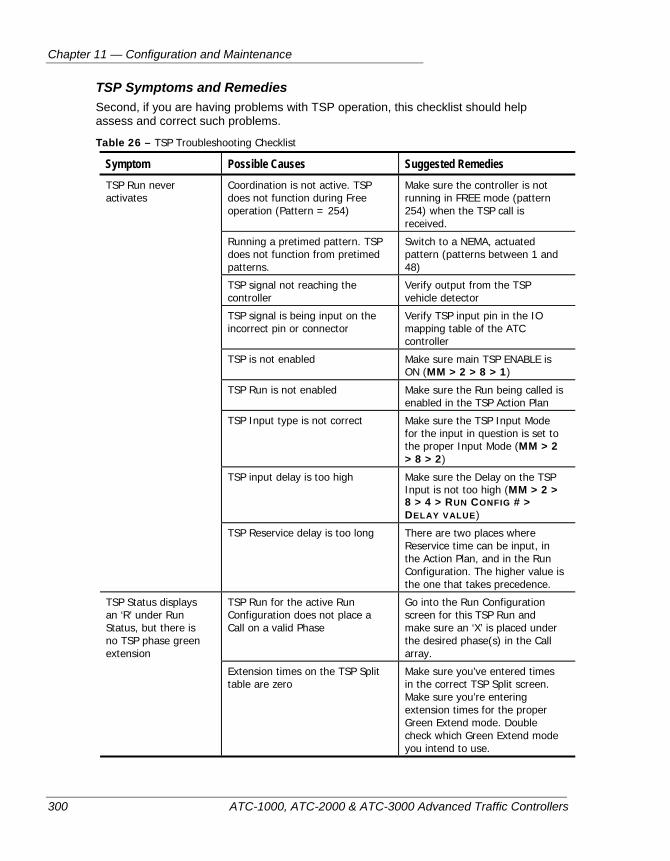
Chapter 11 — Configuration and Maintenance
300 ATC-1000, ATC-2000 & ATC-3000 Advanced Traffic Controllers
TSP Symptoms and Remedies Second, if you are having problems with TSP operation, this checklist should help assess and correct such problems.
Table 26 – TSP Troubleshooting Checklist
Symptom Possible Causes Suggested Remedies Coordination is not active. TSP does not function during Free operation (Pattern = 254)
Make sure the controller is not running in FREE mode (pattern 254) when the TSP call is received.
Running a pretimed pattern. TSP does not function from pretimed patterns.
Switch to a NEMA, actuated pattern (patterns between 1 and 48)
TSP signal not reaching the controller
Verify output from the TSP vehicle detector
TSP signal is being input on the incorrect pin or connector
Verify TSP input pin in the IO mapping table of the ATC controller
TSP is not enabled Make sure main TSP ENABLE is ON (MM > 2 > 8 > 1)
TSP Run is not enabled Make sure the Run being called is enabled in the TSP Action Plan
TSP Input type is not correct Make sure the TSP Input Mode for the input in question is set to the proper Input Mode (MM > 2 > 8 > 2)
TSP input delay is too high Make sure the Delay on the TSP Input is not too high (MM > 2 > 8 > 4 > RUN CONFIG # > DELAY VALUE)
TSP Run never activates
TSP Reservice delay is too long There are two places where Reservice time can be input, in the Action Plan, and in the Run Configuration. The higher value is the one that takes precedence.
TSP Run for the active Run Configuration does not place a Call on a valid Phase
Go into the Run Configuration screen for this TSP Run and make sure an ‘X’ is placed under the desired phase(s) in the Call array.
TSP Status displays an ‘R’ under Run Status, but there is no TSP phase green extension
Extension times on the TSP Split table are zero
Make sure you’ve entered times in the correct TSP Split screen. Make sure you’re entering extension times for the proper Green Extend mode. Double check which Green Extend mode you intend to use.
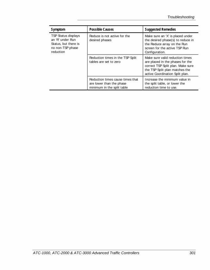
Troubleshooting
ATC-1000, ATC-2000 & ATC-3000 Advanced Traffic Controllers 301
Symptom Possible Causes Suggested Remedies Reduce is not active for the desired phases
Make sure an ‘X’ is placed under the desired phase(s) to reduce in the Reduce array on the Run screen for the active TSP Run Configuration.
Reduction times in the TSP Split tables are set to zero
Make sure valid reduction times are placed in the phases for the correct TSP Split plan. Make sure the TSP Split plan matches the active Coordination Split plan.
TSP Status displays an ‘R’ under Run Status, but there is no non-TSP phase reduction
Reduction times cause times that are lower than the phase minimum in the split table
Increase the minimum value in the split table, or lower the reduction time to use.

Chapter 11 — Configuration and Maintenance
302 ATC-1000, ATC-2000 & ATC-3000 Advanced Traffic Controllers
ATC-1000, ATC-2000 & ATC-3000 Advanced Traffic Controllers 303
Chapter 12 — Controller Specifications
This section details some of the physical characteristics of the ATC-1000 controller. The following topics are discussed in detail in this appendix:
• An overview of the controller’s design, on page 304.
• Physical/environmental specifications, on page 305.
• NTCIP compliance specifications, on page 306.
Chapter 12 — Controller Specifications
304 ATC-1000, ATC-2000 & ATC-3000 Advanced Traffic Controllers
OVERVIEW OF CONTROLLER SPECIFICATIONS
The ATC controllers from Peek are modular, standards-based units that use the Freescale Power Quix 2 hardware platform, with a memory management unit and floating point capabilities. They use the Linux operating system with memory management for process isolation and to ensure operational integrity. They fully support NEMA TS2 Type 1 and TS2 Type 2 functionality and are compliant with NTCIP 1201 and 1202. All of the ATC controllers have three built-in front panel serial ports, two 10/100 Base-T Ethernet ports, a high speed SDLC port for communications to the cabinet BIU(s), and a 3000E-compatible modem slot with full modem flow control support where an optional internal modem can be installed. A high speed USB2 port is standard.
All of the ATC timing functions and clocks are referenced to the 60 Hz AC power line when AC power is available. Thus, the ATC’s timing will track any frequency drift of AC power.
The ATC does not use battery backup for memory storage or the real time clock. Rather, all static memory (SRAM) and the real time clock are powered by a pair of super capacitors, which provide sufficient power to operate the SRAM and clock functions of the controller for up to seven days without AC power. Programs and operation database information is stored and preserved indefinitely in non-volatile flash memory.
The controllers continuously monitor the STOP TIMING function from a conflict monitor, CMU or MMU. They use the transition from ON to OFF to resume proper traffic operation. An ATC controller also sends a watchdog signal (CVM) to the cabinet conflict monitor or fault monitor signal to an MMU, which prevents the cabinet from going into FLASH.
The ATC enforces a minimum time of 3 seconds for each yellow signal. A shorter time for any yellow signal is not allowed, because the CMU identifies a short yellow time as a fault and would automatically put the cabinet into FLASH. This minimum time value is preset in the CMU (2.7 seconds) and is called out in the CMU specification. (Please contact Peek customer support if you wish to override the 3 second yellow rule.)
The Peek ATC controllers can be interrogated by a Microsoft Windows®-based software package known as ATC Link™ running on an external computer for setting and retrieving data from the unit via the front panel serial or Ethernet ports. This same capability is also available from Peek’s central system software package: IQ Central™. The front panel display and keypad can be used to view the status of the controller, view most of the available program parameters, and also to modify the programming of the unit.
All of the ATC controllers feature dual traffic applications, so they can handle either interval-based or phase-based operations. These applications are fully NTCIP-compliant implementations that easily integrate into any NTCIP-compliant ITS or traffic control system.
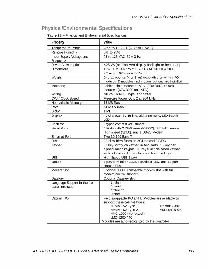
Overview of Controller Specifications
ATC-1000, ATC-2000 & ATC-3000 Advanced Traffic Controllers 305
Physical/Environmental Specifications Table 27 – Physical and Environmental Specifications
Property Value Temperature Range –35° to +165° F (–37° to +74° C) Relative Humidity 0% to 95% Input Supply Voltage and Frequency
95 to 135 VAC, 60 ± 3 Hz
Power Consumption <25 VA (nominal w/o display backlight or heater on) Dimensions 10¼” H x 14¾” W x 10½” D (ATC-1000 & 2000)
261mm × 375mm × 267mm Weight 9 to 11 pounds (4 to 5 kg) depending on which I/O
modules, D modules and modem options are installed Mounting Cabinet shelf mounted (ATC-1000/2000) or rack-
mounted (ATC-3000 and ATCi) Wiring MIL-W 16878D, Type B or better CPU / Clock Speed Freescale Power Quix 2 at 300 MHz Non-volatile Memory 16 MB Flash RAM 64 MB SDRAM SRAM 1 MB Display 40 character by 16 line, alpha-numeric, LED-backlit
LCD Contrast Keypad contrast adjustment Serial Ports 4 Ports with 2 DB-9 male (RS-232); 1 DB-15 female
High speed (SDLC), and 1 DB-25 Modem Ethernet Port Two 10/100 Base-T Fuse 2A slow-blow fuses on AC Line and 24VDC Keypad 32 key softtouch keypad in two parts: 16 key hex
alphanumeric keypad. 16 key function-based keypad with color-coded navigation and function keys
USB High Speed USB-2 port Lamps 6 power monitor LEDs. Heartbeat LED, and 12 port
status LEDs Modem Slot Optional 3000E compatible modem slot with full
modem control support DataKey Optional Datakey slot Language Support in the front panel interface
English Spanish Afrikaans French
Cabinet I/O Field swappable I/O and D Modules are available to support these cabinet types:
NEMA TS2 Type 1 Traconex 390 NEMA TS2 Type 2 Multisonics 820 HMC-1000 (Honeywell) LMD-9200 / 40
Modules are auto-recognized by the controller
Chapter 12 — Controller Specifications
306 ATC-1000, ATC-2000 & ATC-3000 Advanced Traffic Controllers
NTCIP Compliance The Peek ATC controllers use the Ethernet ports to communicate with the central computer using NTCIP (National Transportation Communications for ITS Protocol). NTCIP conforms to NEMA TS2-2003 for Pretimed Type 1 (P1N Level 2) controllers.
The NTCIP communications support adheres to the following timing constraints: whenever a message is received by the controller and that requires the controller to respond, (e.g. all messages except a broadcast message) the controller will initiate its response (i.e., start the transmission of data) within 40 ms. Further, the data is transmitted continuously (i.e., no gaps between characters) until the transmission is complete.
Once-per-second communications will be critical to the central management of the controllers. NTCIP relies on “dynamic object” capability to allow the central computer to program a list of data items to be returned in response to a “short-hand” request. The controller will support dynamic objects.
The controller supports the concept of “logical blocks”. Peek Traffic and US Traffic have defined NTCIP manufacturer proprietary objects that encapsulate a group of data elements (e.g., phase timings block, coordination plan block, detector configuration block, etc.). By grouping the objects into blocks, the bandwidth required to transfer the data is reduced, and, since the bulk of the NTCIP overhead is in the object headers and identifiers, transfer time is much more sensitive to the number of blocks than to the size of each block. However, the storage medium and update procedures do not interfere with rapid data transfer. Upon receipt of a database download block, the controller responds within the timing envelope described. In addition, the receipt of multiple database download blocks in rapid succession does not result in any communications errors, NTCIP (SNMP) error codes, or communications turn-around delays.
ATC-1000, ATC-2000 & ATC-3000 Advanced Traffic Controllers 307
Chapter 13 — Serial and Data Connectors
This appendix provides details about the serial ports and data connectors of the ATC-1000 controller, including pin locations and functions. The following topics are discussed in detail in this chapter:
• Port 1, the SDLC port, on page 308.
• Port 2, the RS-232 connector, on page 309.
• Port 3, the optional 2070 connector, on page 310.
• Port 4, the Local serial connector, on page 311.
• Port 5, the SPARE port, on page 312.
• Ethernet ports, on page 313.
• USB ports, on page 314.
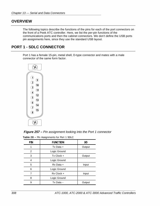
Chapter 13 — Serial and Data Connectors
308 ATC-1000, ATC-2000 & ATC-3000 Advanced Traffic Controllers
OVERVIEW
The following topics describe the functions of the pins for each of the port connectors on the front of a Peek ATC controller. Here, we list the per-pin functions of the communications ports and then the cabinet connectors. We don’t define the USB ports pin assignments here, since they use the standard USB layout.
PORT 1 - SDLC CONNECTOR
Port 1 has a female 15-pin, metal shell, D-type connector and mates with a male connector of the same form factor.
19
10
11
12
13
14
15
2
3
4
5
6
7
8
Figure 257 – Pin assignment looking into the Port 1 connector
Table 28 – Pin Assignments for Port 1 SDLC
PIN FUNCTION I/O 1 Tx Data + Output
2 Logic Ground
3 Tx Clock + Output
4 Logic Ground
5 Rx Data + Input
6 Logic Ground
7 Rx Clock + Input
8 Logic Ground
9 Tx Data – Output
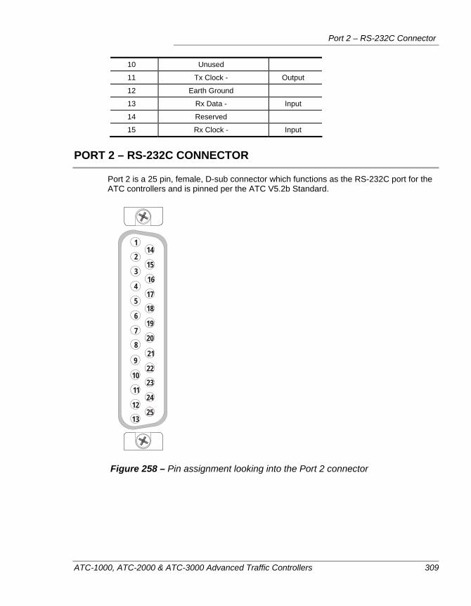
Port 2 – RS-232C Connector
ATC-1000, ATC-2000 & ATC-3000 Advanced Traffic Controllers 309
10 Unused
11 Tx Clock - Output
12 Earth Ground
13 Rx Data - Input
14 Reserved
15 Rx Clock - Input
PORT 2 – RS-232C CONNECTOR
Port 2 is a 25 pin, female, D-sub connector which functions as the RS-232C port for the ATC controllers and is pinned per the ATC V5.2b Standard.
114
9
15
10
16
21
11
17
22
12
18
23
13
19
24
20
25
2
3
4
5
6
7
8
Figure 258 – Pin assignment looking into the Port 2 connector
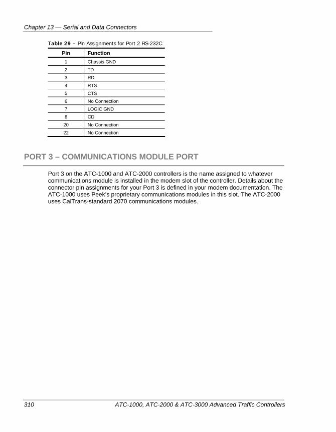
Chapter 13 — Serial and Data Connectors
310 ATC-1000, ATC-2000 & ATC-3000 Advanced Traffic Controllers
Table 29 – Pin Assignments for Port 2 RS-232C
Pin Function 1 Chassis GND
2 TD
3 RD
4 RTS
5 CTS
6 No Connection
7 LOGIC GND
8 CD
20 No Connection
22 No Connection
PORT 3 – COMMUNICATIONS MODULE PORT
Port 3 on the ATC-1000 and ATC-2000 controllers is the name assigned to whatever communications module is installed in the modem slot of the controller. Details about the connector pin assignments for your Port 3 is defined in your modem documentation. The ATC-1000 uses Peek’s proprietary communications modules in this slot. The ATC-2000 uses CalTrans-standard 2070 communications modules.
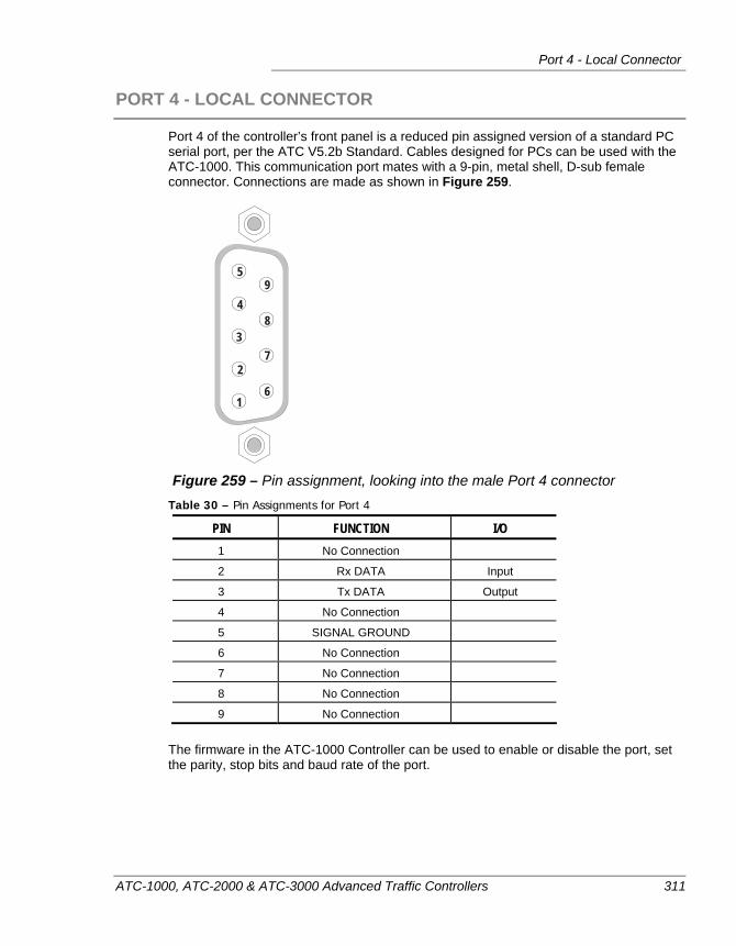
Port 4 - Local Connector
ATC-1000, ATC-2000 & ATC-3000 Advanced Traffic Controllers 311
PORT 4 - LOCAL CONNECTOR
Port 4 of the controller’s front panel is a reduced pin assigned version of a standard PC serial port, per the ATC V5.2b Standard. Cables designed for PCs can be used with the ATC-1000. This communication port mates with a 9-pin, metal shell, D-sub female connector. Connections are made as shown in Figure 259.
1
2
6
37
48
59
Figure 259 – Pin assignment, looking into the male Port 4 connector
Table 30 – Pin Assignments for Port 4
PIN FUNCTION I/O 1 No Connection
2 Rx DATA Input
3 Tx DATA Output
4 No Connection
5 SIGNAL GROUND
6 No Connection
7 No Connection
8 No Connection
9 No Connection
The firmware in the ATC-1000 Controller can be used to enable or disable the port, set the parity, stop bits and baud rate of the port.
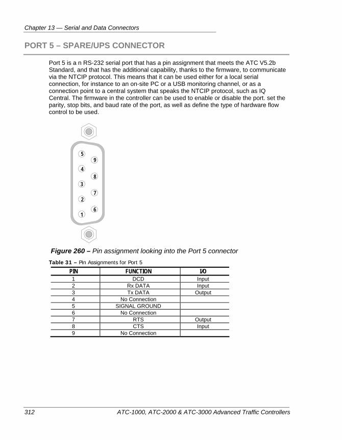
Chapter 13 — Serial and Data Connectors
312 ATC-1000, ATC-2000 & ATC-3000 Advanced Traffic Controllers
PORT 5 – SPARE/UPS CONNECTOR
Port 5 is a n RS-232 serial port that has a pin assignment that meets the ATC V5.2b Standard, and that has the additional capability, thanks to the firmware, to communicate via the NTCIP protocol. This means that it can be used either for a local serial connection, for instance to an on-site PC or a USB monitoring channel, or as a connection point to a central system that speaks the NTCIP protocol, such as IQ Central. The firmware in the controller can be used to enable or disable the port. set the parity, stop bits, and baud rate of the port, as well as define the type of hardware flow control to be used.
1
2
6
37
48
59
Figure 260 – Pin assignment looking into the Port 5 connector
Table 31 – Pin Assignments for Port 5
PIN FUNCTION I/O 1 DCD Input 2 Rx DATA Input 3 Tx DATA Output 4 No Connection 5 SIGNAL GROUND 6 No Connection 7 RTS Output 8 CTS Input 9 No Connection
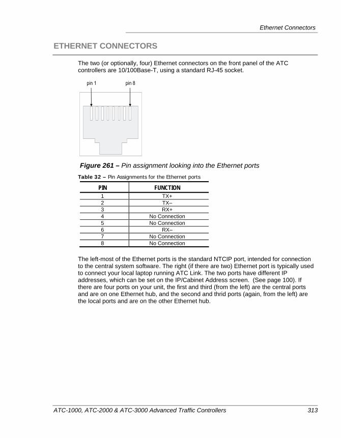
Ethernet Connectors
ATC-1000, ATC-2000 & ATC-3000 Advanced Traffic Controllers 313
ETHERNET CONNECTORS
The two (or optionally, four) Ethernet connectors on the front panel of the ATC controllers are 10/100Base-T, using a standard RJ-45 socket.
Figure 261 – Pin assignment looking into the Ethernet ports
Table 32 – Pin Assignments for the Ethernet ports
PIN FUNCTION 1 TX+ 2 TX– 3 RX+ 4 No Connection 5 No Connection 6 RX– 7 No Connection 8 No Connection
The left-most of the Ethernet ports is the standard NTCIP port, intended for connection to the central system software. The right (if there are two) Ethernet port is typically used to connect your local laptop running ATC Link. The two ports have different IP addresses, which can be set on the IP/Cabinet Address screen. (See page 100). If there are four ports on your unit, the first and third (from the left) are the central ports and are on one Ethernet hub, and the second and thrid ports (again, from the left) are the local ports and are on the other Ethernet hub.
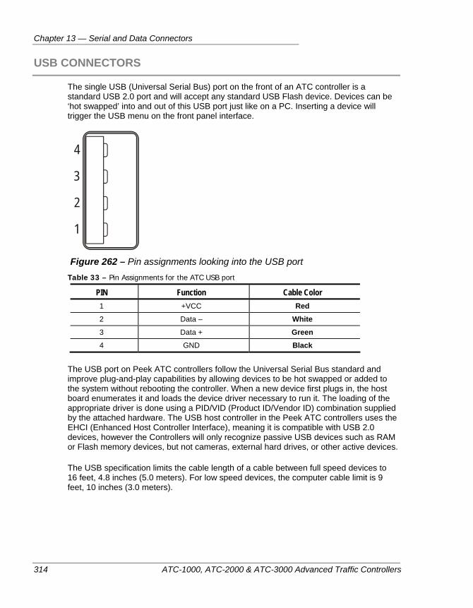
Chapter 13 — Serial and Data Connectors
314 ATC-1000, ATC-2000 & ATC-3000 Advanced Traffic Controllers
USB CONNECTORS
The single USB (Universal Serial Bus) port on the front of an ATC controller is a standard USB 2.0 port and will accept any standard USB Flash device. Devices can be ‘hot swapped’ into and out of this USB port just like on a PC. Inserting a device will trigger the USB menu on the front panel interface.
1
2
3
4
Figure 262 – Pin assignments looking into the USB port
Table 33 – Pin Assignments for the ATC USB port
PIN Function Cable Color 1 +VCC Red
2 Data – White
3 Data + Green
4 GND Black
The USB port on Peek ATC controllers follow the Universal Serial Bus standard and improve plug-and-play capabilities by allowing devices to be hot swapped or added to the system without rebooting the controller. When a new device first plugs in, the host board enumerates it and loads the device driver necessary to run it. The loading of the appropriate driver is done using a PID/VID (Product ID/Vendor ID) combination supplied by the attached hardware. The USB host controller in the Peek ATC controllers uses the EHCI (Enhanced Host Controller Interface), meaning it is compatible with USB 2.0 devices, however the Controllers will only recognize passive USB devices such as RAM or Flash memory devices, but not cameras, external hard drives, or other active devices.
The USB specification limits the cable length of a cable between full speed devices to 16 feet, 4.8 inches (5.0 meters). For low speed devices, the computer cable limit is 9 feet, 10 inches (3.0 meters).
ATC-1000, ATC-2000 & ATC-3000 Advanced Traffic Controllers 315
Chapter 14 — I/O Module Connector Details
This appendix provides details about the ports and connectors on the various Input/Output modules available for the ATC-1000 controller, including pin locations and functions. The following topics are discussed in detail in this chapter:
• TS2 Type 1 Connectors, on page 316.
• TS2 Type 2 I/O Connectors, on page 318.
• HMC-1000 I/O Connectors, on page 328.
• LMD I/O Connectors, on page 331.
• Closed Loop D Module, on page 338.
• LMD 9200 D Module, on page 341.
• Traconex D Module, on page 343.
• Multisonics D Module, on page 345.
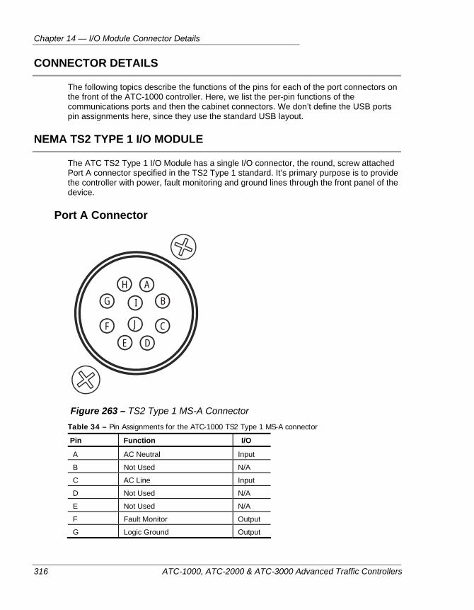
Chapter 14 — I/O Module Connector Details
316 ATC-1000, ATC-2000 & ATC-3000 Advanced Traffic Controllers
CONNECTOR DETAILS
The following topics describe the functions of the pins for each of the port connectors on the front of the ATC-1000 controller. Here, we list the per-pin functions of the communications ports and then the cabinet connectors. We don’t define the USB ports pin assignments here, since they use the standard USB layout.
NEMA TS2 TYPE 1 I/O MODULE
The ATC TS2 Type 1 I/O Module has a single I/O connector, the round, screw attached Port A connector specified in the TS2 Type 1 standard. It’s primary purpose is to provide the controller with power, fault monitoring and ground lines through the front panel of the device.
Port A Connector
AHBG I
J CFDE
Figure 263 – TS2 Type 1 MS-A Connector
Table 34 – Pin Assignments for the ATC-1000 TS2 Type 1 MS-A connector
Pin Function I/O
A AC Neutral Input
B Not Used N/A
C AC Line Input
D Not Used N/A
E Not Used N/A
F Fault Monitor Output
G Logic Ground Output
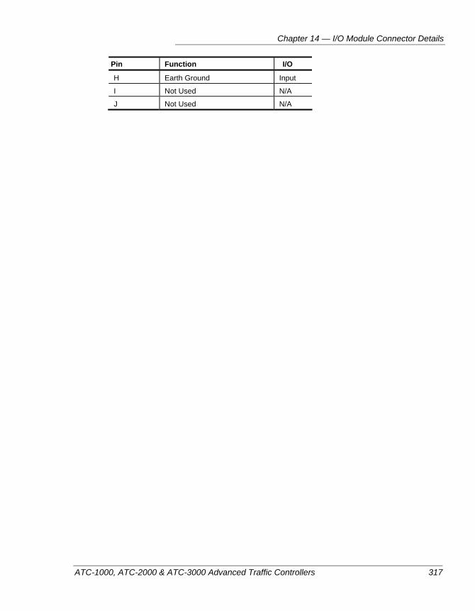
Chapter 14 — I/O Module Connector Details
ATC-1000, ATC-2000 & ATC-3000 Advanced Traffic Controllers 317
Pin Function I/O
H Earth Ground Input
I Not Used N/A
J Not Used N/A
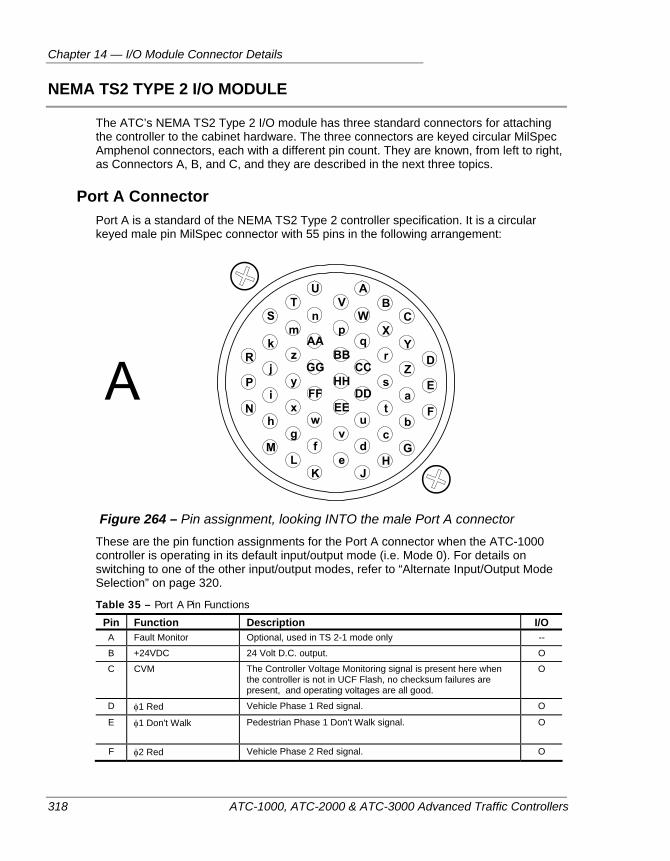
Chapter 14 — I/O Module Connector Details
318 ATC-1000, ATC-2000 & ATC-3000 Advanced Traffic Controllers
NEMA TS2 TYPE 2 I/O MODULE
The ATC’s NEMA TS2 Type 2 I/O module has three standard connectors for attaching the controller to the cabinet hardware. The three connectors are keyed circular MilSpec Amphenol connectors, each with a different pin count. They are known, from left to right, as Connectors A, B, and C, and they are described in the next three topics.
Port A Connector Port A is a standard of the NEMA TS2 Type 2 controller specification. It is a circular keyed male pin MilSpec connector with 55 pins in the following arrangement:
Figure 264 – Pin assignment, looking INTO the male Port A connector
These are the pin function assignments for the Port A connector when the ATC-1000 controller is operating in its default input/output mode (i.e. Mode 0). For details on switching to one of the other input/output modes, refer to “Alternate Input/Output Mode Selection” on page 320.
Table 35 – Port A Pin Functions
Pin Function Description I/O A Fault Monitor Optional, used in TS 2-1 mode only --
B +24VDC 24 Volt D.C. output. O
C CVM The Controller Voltage Monitoring signal is present here when the controller is not in UCF Flash, no checksum failures are present, and operating voltages are all good.
O
D φ1 Red Vehicle Phase 1 Red signal. O
E φ1 Don't Walk Pedestrian Phase 1 Don't Walk signal. O
F φ2 Red Vehicle Phase 2 Red signal. O
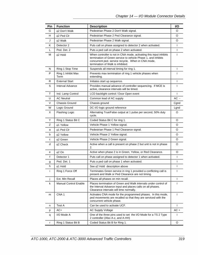
Chapter 14 — I/O Module Connector Details
ATC-1000, ATC-2000 & ATC-3000 Advanced Traffic Controllers 319
Pin Function Description I/O G φ2 Don't Walk Pedestrian Phase 2 Don't Walk signal. O
H φ2 Ped Clr Pedestrian Phase 2 Ped Clearance signal. O
J φ2 Walk Pedestrian Phase 2 Walk signal. O
K Detector 2 Puts call on phase assigned to detector 2 when activated. I
L Ped. Det. 2 Puts a ped call on phase 2 when activated. I
M φ2 Hold When controller is not in CNA mode, activating this input inhibits termination of Green service to vehicle Phase 1, and inhibits concurrent ped. service recycle. When in CNA mode, termination of Walk is inhibited.
I
N Ring 1 Stop Time Suspends all interval timing for ring 1. I
P Ring 1 Inhibit Max Term
Prevents max termination of ring 1 vehicle phases when extending.
I
R External Start Initiates start up sequence. I
S Interval Advance Provides manual advance of controller sequencing. If MCE is active, clearance intervals will be timed.
I
T Ind. Lamp Control LCD backlight control / Door Open event I
U AC Neutral Common lead of AC supply AC -
V Chassis Ground Chassis ground Cgnd
W Logic Ground DC I/O logic ground reference Lgnd
X Flashing Logic Alternating True/False output at 1 pulse per second, 50% duty cycle.
O
Y Ring 1 Status Bit C Coded Status Bit C for ring 1. O
Z φ1 Yellow Vehicle Phase 1 Yellow signal. O
a φ1 Ped Clr Pedestrian Phase 1 Ped Clearance signal. O
b φ2 Yellow Vehicle Phase 2 Yellow signal. O
c φ2 Green Vehicle Phase 2 Green signal. O
d φ2 Check Active when a call is present on phase 2 but unit is not in phase 2.
O
e φ2 On Active when phase 2 is in Green, Yellow, or Red Clearance. O
f Detector 1 Puts call on phase assigned to detector 1 when activated. I
g Ped. Det. 1 Puts a ped call on phase 1 when activated. I
h φ1 Hold See φ2 Hold description above I
i Ring 1 Force Off Terminates Green service in ring 1 provided a conflicting call is present and Walk or Ped Clearance are not timing.
I
j Ext. Min Recall Places all phases on min recall. I
k Manual Control Enable Places termination of Green and Walk intervals under control of the Interval Advance input and places calls on all phases. Clearance intervals will time normally.
I
m CNA 1 Activates CNA mode for the programmed phases. In this mode, ped movements are recalled so that they are serviced with the concurrent vehicle phase.
I
n Test A Can be used to activate UCF. I
p AC+ AC Supply Voltage AC +
q I/O Mode A One of the three pins used to set the I/O Mode for a TS 2 Type 2 controller (Also A-z, and A-HH)
I
r Ring 1 Status Bit B Coded Status Bit B for Ring 1. O
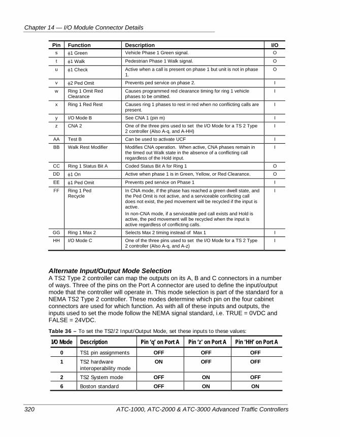
Chapter 14 — I/O Module Connector Details
320 ATC-1000, ATC-2000 & ATC-3000 Advanced Traffic Controllers
Pin Function Description I/O s φ1 Green Vehicle Phase 1 Green signal. O
t φ1 Walk Pedestrian Phase 1 Walk signal. O
u φ1 Check Active when a call is present on phase 1 but unit is not in phase 1.
O
v φ2 Ped Omit Prevents ped service on phase 2. I
w Ring 1 Omit Red Clearance
Causes programmed red clearance timing for ring 1 vehicle phases to be omitted.
I
x Ring 1 Red Rest Causes ring 1 phases to rest in red when no conflicting calls are present.
I
y I/O Mode B See CNA 1 (pin m) I
z CNA 2 One of the three pins used to set the I/O Mode for a TS 2 Type 2 controller (Also A-q, and A-HH)
I
AA Test B Can be used to activate UCF I
BB Walk Rest Modifier Modifies CNA operation. When active, CNA phases remain in the timed out Walk state in the absence of a conflicting call regardless of the Hold input.
I
CC Ring 1 Status Bit A Coded Status Bit A for Ring 1 O
DD φ1 On Active when phase 1 is in Green, Yellow, or Red Clearance. O
EE φ1 Ped Omit Prevents ped service on Phase 1 I
FF Ring 1 Ped Recycle
In CNA mode, if the phase has reached a green dwell state, and the Ped Omit is not active, and a serviceable conflicting call does not exist, the ped movement will be recycled if the input is active. In non-CNA mode, if a serviceable ped call exists and Hold is active, the ped movement will be recycled when the input is active regardless of conflicting calls.
I
GG Ring 1 Max 2 Selects Max 2 timing instead of Max 1 I
HH I/O Mode C One of the three pins used to set the I/O Mode for a TS 2 Type 2 controller (Also A-q, and A-z)
I
Alternate Input/Output Mode Selection A TS2 Type 2 controller can map the outputs on its A, B and C connectors in a number of ways. Three of the pins on the Port A connector are used to define the input/output mode that the controller will operate in. This mode selection is part of the standard for a NEMA TS2 Type 2 controller. These modes determine which pin on the four cabinet connectors are used for which function. As with all of these inputs and outputs, the inputs used to set the mode follow the NEMA signal standard, i.e. TRUE = 0VDC and FALSE = 24VDC.
Table 36 – To set the TS2/2 Input/Output Mode, set these inputs to these values:
I/O Mode Description Pin ‘q’ on Port A Pin ‘z’ on Port A Pin ‘HH’ on Port A 0 TS1 pin assignments OFF OFF OFF
1 TS2 hardware interoperability mode
ON OFF OFF
2 TS2 System mode OFF ON OFF
6 Boston standard OFF ON ON
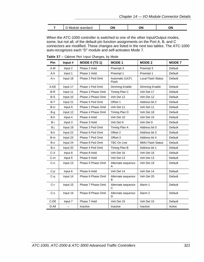
Chapter 14 — I/O Module Connector Details
ATC-1000, ATC-2000 & ATC-3000 Advanced Traffic Controllers 321
7 D Module standard ON ON ON
When the ATC-1000 controller is switched to one of the other Input/Output modes, some, but not all, of the default pin function assignments on the Port A, B, and C connectors are modified. These changes are listed in the next two tables. The ATC-1000 auto-recognizes each “D” module and self-activates Mode 7.
Table 37 – Cabinet Port Input Changes, by Mode
Pin Input # MODE 0 (TS 1) MODE 1 MODE 2 MODE 7 A-M Input 2 Phase 2 Hold Preempt 3 Preempt 3 Default
A-h Input 1 Phase 1 Hold Preempt 1 Preempt 1 Default
A-v Input 18 Phase 2 Ped Omit Automatic (UCF) Flash
Local Flash Status Default
A-EE Input 17 Phase 1 Ped Omit Dimming Enable Dimming Enable Default
B-R Input 11 Phase 3 Phase Omit Timing Plan C Veh Det 17 Default
B-S Input 10 Phase 2 Phase Omit Veh Det 12 Veh Det 12 Default
B-T Input 21 Phase 5 Ped Omit Offset 1 Address bit 2 Default
B-U Input 9 Phase 1 Phase Omit Veh Det 11 Veh Det 11 Default
B-g Input 12 Phase 4 Phase Omit Timing Plan D Veh Det 18 Default
B-h Input 4 Phase 4 Hold Veh Det 10 Veh Det 10 Default
B-i Input 3 Phase 3 Hold Veh Det 9 Veh Det 9 Default
B-j Input 19 Phase 3 Ped Omit Timing Plan A Address bit 0 Default
B-k Input 22 Phase 6 Ped Omit Offset 2 Address bit 3 Default
B-m Input 23 Phase 7 Ped Omit Offset 3 Address bit 4 Default
B-n Input 24 Phase 8 Ped Omit TBC On Line MMU Flash Status Default
B-x Input 20 Phase 4 Ped Omit Timing Plan B Address bit 1 Default
C-X Input 8 Phase 8 Hold Veh Det 16 Veh Det 16 Default
C-m Input 5 Phase 5 Hold Veh Det 13 Veh Det 13 Default
C-n Input 13 Phase 5 Phase Omit Alternate sequence A
Veh Det 19 Default
C-p Input 6 Phase 6 Hold Veh Det 14 Veh Det 14 Default
C-q Input 14 Phase 6 Phase Omit Alternate sequence B
Veh Det 20 Default
C-r Input 15 Phase 7 Phase Omit Alternate sequence C
Alarm 1 Default
C-s Input 16 Phase 8 Phase Omit Alternate sequence D
Alarm 2 Default
C-EE Input 7 Phase 7 Hold Veh Det 15 Veh Det 15 Default
D-All -- Inactive Inactive Inactive Active
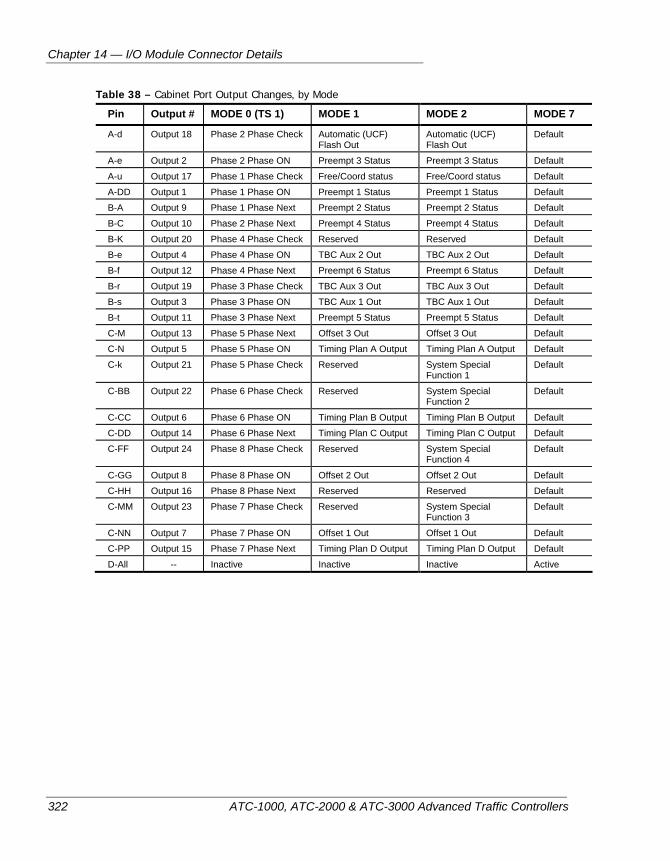
Chapter 14 — I/O Module Connector Details
322 ATC-1000, ATC-2000 & ATC-3000 Advanced Traffic Controllers
Table 38 – Cabinet Port Output Changes, by Mode
Pin Output # MODE 0 (TS 1) MODE 1 MODE 2 MODE 7
A-d Output 18 Phase 2 Phase Check Automatic (UCF) Flash Out
Automatic (UCF) Flash Out
Default
A-e Output 2 Phase 2 Phase ON Preempt 3 Status Preempt 3 Status Default
A-u Output 17 Phase 1 Phase Check Free/Coord status Free/Coord status Default
A-DD Output 1 Phase 1 Phase ON Preempt 1 Status Preempt 1 Status Default
B-A Output 9 Phase 1 Phase Next Preempt 2 Status Preempt 2 Status Default
B-C Output 10 Phase 2 Phase Next Preempt 4 Status Preempt 4 Status Default
B-K Output 20 Phase 4 Phase Check Reserved Reserved Default
B-e Output 4 Phase 4 Phase ON TBC Aux 2 Out TBC Aux 2 Out Default
B-f Output 12 Phase 4 Phase Next Preempt 6 Status Preempt 6 Status Default
B-r Output 19 Phase 3 Phase Check TBC Aux 3 Out TBC Aux 3 Out Default
B-s Output 3 Phase 3 Phase ON TBC Aux 1 Out TBC Aux 1 Out Default
B-t Output 11 Phase 3 Phase Next Preempt 5 Status Preempt 5 Status Default
C-M Output 13 Phase 5 Phase Next Offset 3 Out Offset 3 Out Default
C-N Output 5 Phase 5 Phase ON Timing Plan A Output Timing Plan A Output Default
C-k Output 21 Phase 5 Phase Check Reserved System Special Function 1
Default
C-BB Output 22 Phase 6 Phase Check Reserved System Special Function 2
Default
C-CC Output 6 Phase 6 Phase ON Timing Plan B Output Timing Plan B Output Default
C-DD Output 14 Phase 6 Phase Next Timing Plan C Output Timing Plan C Output Default
C-FF Output 24 Phase 8 Phase Check Reserved System Special Function 4
Default
C-GG Output 8 Phase 8 Phase ON Offset 2 Out Offset 2 Out Default
C-HH Output 16 Phase 8 Phase Next Reserved Reserved Default
C-MM Output 23 Phase 7 Phase Check Reserved System Special Function 3
Default
C-NN Output 7 Phase 7 Phase ON Offset 1 Out Offset 1 Out Default
C-PP Output 15 Phase 7 Phase Next Timing Plan D Output Timing Plan D Output Default
D-All -- Inactive Inactive Inactive Active
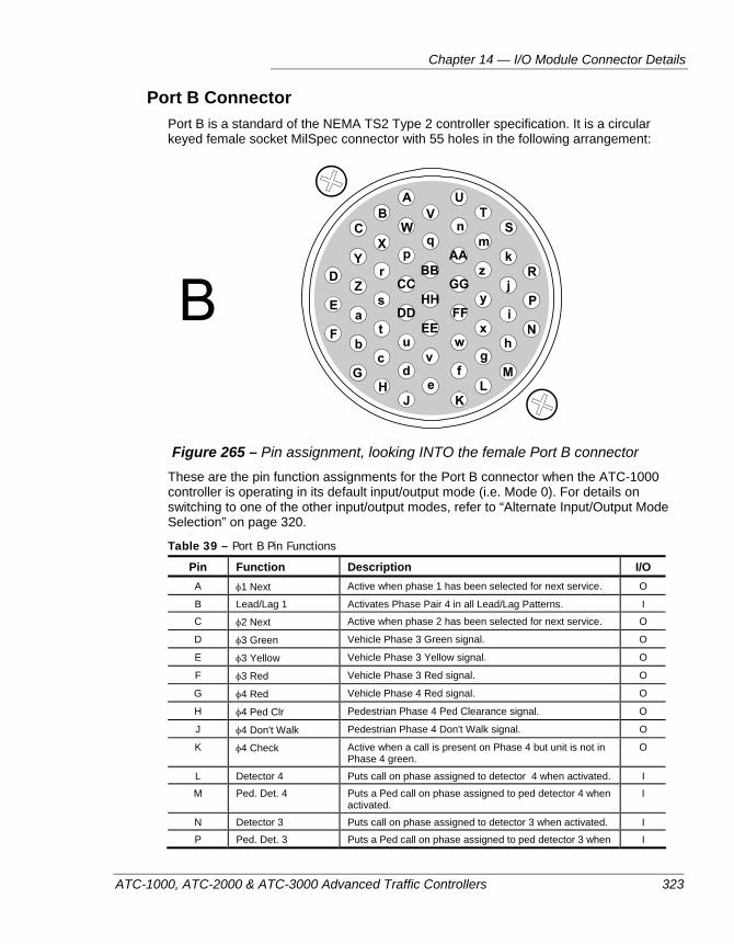
Chapter 14 — I/O Module Connector Details
ATC-1000, ATC-2000 & ATC-3000 Advanced Traffic Controllers 323
Port B Connector Port B is a standard of the NEMA TS2 Type 2 controller specification. It is a circular keyed female socket MilSpec connector with 55 holes in the following arrangement:
Figure 265 – Pin assignment, looking INTO the female Port B connector
These are the pin function assignments for the Port B connector when the ATC-1000 controller is operating in its default input/output mode (i.e. Mode 0). For details on switching to one of the other input/output modes, refer to “Alternate Input/Output Mode Selection” on page 320.
Table 39 – Port B Pin Functions
Pin Function Description I/O A φ1 Next Active when phase 1 has been selected for next service. O
B Lead/Lag 1 Activates Phase Pair 4 in all Lead/Lag Patterns. I
C φ2 Next Active when phase 2 has been selected for next service. O
D φ3 Green Vehicle Phase 3 Green signal. O
E φ3 Yellow Vehicle Phase 3 Yellow signal. O
F φ3 Red Vehicle Phase 3 Red signal. O
G φ4 Red Vehicle Phase 4 Red signal. O
H φ4 Ped Clr Pedestrian Phase 4 Ped Clearance signal. O
J φ4 Don't Walk Pedestrian Phase 4 Don't Walk signal. O
K φ4 Check Active when a call is present on Phase 4 but unit is not in Phase 4 green.
O
L Detector 4 Puts call on phase assigned to detector 4 when activated. I
M Ped. Det. 4 Puts a Ped call on phase assigned to ped detector 4 when activated.
I
N Detector 3 Puts call on phase assigned to detector 3 when activated. I
P Ped. Det. 3 Puts a Ped call on phase assigned to ped detector 3 when I
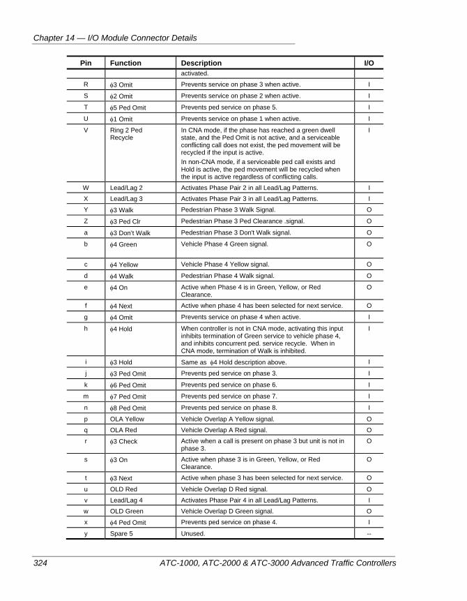
Chapter 14 — I/O Module Connector Details
324 ATC-1000, ATC-2000 & ATC-3000 Advanced Traffic Controllers
Pin Function Description I/O activated.
R φ3 Omit Prevents service on phase 3 when active. I
S φ2 Omit Prevents service on phase 2 when active. I
T φ5 Ped Omit Prevents ped service on phase 5. I
U φ1 Omit Prevents service on phase 1 when active. I
V Ring 2 Ped Recycle
In CNA mode, if the phase has reached a green dwell state, and the Ped Omit is not active, and a serviceable conflicting call does not exist, the ped movement will be recycled if the input is active. In non-CNA mode, if a serviceable ped call exists and Hold is active, the ped movement will be recycled when the input is active regardless of conflicting calls.
I
W Lead/Lag 2 Activates Phase Pair 2 in all Lead/Lag Patterns. I
X Lead/Lag 3 Activates Phase Pair 3 in all Lead/Lag Patterns. I
Y φ3 Walk Pedestrian Phase 3 Walk Signal. O
Z φ3 Ped Clr Pedestrian Phase 3 Ped Clearance .signal. O
a φ3 Don’t Walk Pedestrian Phase 3 Don't Walk signal. O
b φ4 Green Vehicle Phase 4 Green signal.
O
c φ4 Yellow Vehicle Phase 4 Yellow signal. O
d φ4 Walk Pedestrian Phase 4 Walk signal. O
e φ4 On Active when Phase 4 is in Green, Yellow, or Red Clearance.
O
f φ4 Next Active when phase 4 has been selected for next service. O
g φ4 Omit Prevents service on phase 4 when active. I
h φ4 Hold When controller is not in CNA mode, activating this input inhibits termination of Green service to vehicle phase 4, and inhibits concurrent ped. service recycle. When in CNA mode, termination of Walk is inhibited.
I
i φ3 Hold Same as φ4 Hold description above. I
j φ3 Ped Omit Prevents ped service on phase 3. I
k φ6 Ped Omit Prevents ped service on phase 6. I
m φ7 Ped Omit Prevents ped service on phase 7. I
n φ8 Ped Omit Prevents ped service on phase 8. I
p OLA Yellow Vehicle Overlap A Yellow signal. O
q OLA Red Vehicle Overlap A Red signal. O
r φ3 Check Active when a call is present on phase 3 but unit is not in phase 3.
O
s φ3 On Active when phase 3 is in Green, Yellow, or Red Clearance.
O
t φ3 Next Active when phase 3 has been selected for next service. O
u OLD Red Vehicle Overlap D Red signal. O
v Lead/Lag 4 Activates Phase Pair 4 in all Lead/Lag Patterns. I
w OLD Green Vehicle Overlap D Green signal. O
x φ4 Ped Omit Prevents ped service on phase 4. I
y Spare 5 Unused. --
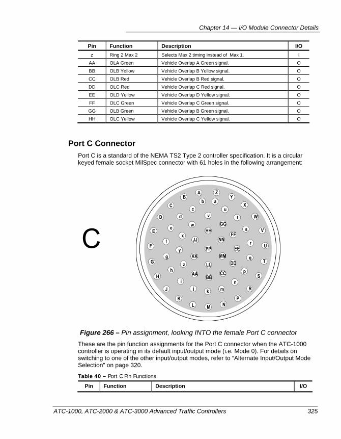
Chapter 14 — I/O Module Connector Details
ATC-1000, ATC-2000 & ATC-3000 Advanced Traffic Controllers 325
Pin Function Description I/O z Ring 2 Max 2 Selects Max 2 timing instead of Max 1. I
AA OLA Green Vehicle Overlap A Green signal. O
BB OLB Yellow Vehicle Overlap B Yellow signal. O
CC OLB Red Vehicle Overlap B Red signal. O
DD OLC Red Vehicle Overlap C Red signal. O
EE OLD Yellow Vehicle Overlap D Yellow signal. O
FF OLC Green Vehicle Overlap C Green signal. O
GG OLB Green Vehicle Overlap B Green signal. O
HH OLC Yellow Vehicle Overlap C Yellow signal. O
Port C Connector Port C is a standard of the NEMA TS2 Type 2 controller specification. It is a circular keyed female socket MilSpec connector with 61 holes in the following arrangement:
Figure 266 – Pin assignment, looking INTO the female Port C connector
These are the pin function assignments for the Port C connector when the ATC-1000 controller is operating in its default input/output mode (i.e. Mode 0). For details on switching to one of the other input/output modes, refer to “Alternate Input/Output Mode Selection” on page 320.
Table 40 – Port C Pin Functions
Pin Function Description I/O
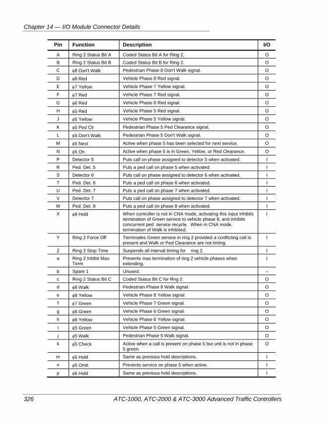
Chapter 14 — I/O Module Connector Details
326 ATC-1000, ATC-2000 & ATC-3000 Advanced Traffic Controllers
Pin Function Description I/O
A Ring 2 Status Bit A Coded Status Bit A for Ring 2. O
B Ring 2 Status Bit B Coded Status Bit B for Ring 2. O
C φ8 Don't Walk Pedestrian Phase 8 Don't Walk signal. O
D φ8 Red Vehicle Phase 8 Red signal. O
E φ7 Yellow Vehicle Phase 7 Yellow signal. O
F φ7 Red Vehicle Phase 7 Red signal. O
G φ6 Red Vehicle Phase 6 Red signal. O
H φ5 Red Vehicle Phase 5 Red signal. O
J φ5 Yellow Vehicle Phase 5 Yellow signal. O
K φ5 Ped Clr Pedestrian Phase 5 Ped Clearance signal. O
L φ5 Don't Walk Pedestrian Phase 5 Don't Walk signal. O
M φ5 Next Active when phase 5 has been selected for next service. O
N φ5 On Active when phase 5 is in Green, Yellow, or Red Clearance. O
P Detector 5 Puts call on phase assigned to detector 5 when activated. I
R Ped. Det. 5 Puts a ped call on phase 5 when activated. I
S Detector 6 Puts call on phase assigned to detector 6 when activated. I
T Ped. Det. 6 Puts a ped call on phase 6 when activated. I
U Ped. Det. 7 Puts a ped call on phase 7 when activated. I
V Detector 7 Puts call on phase assigned to detector 7 when activated. I
W Ped. Det. 8 Puts a ped call on phase 8 when activated. I
X φ8 Hold When controller is not in CNA mode, activating this input inhibits termination of Green service to vehicle phase 8, and inhibits concurrent ped. service recycle. When in CNA mode, termination of Walk is inhibited.
I
Y Ring 2 Force Off Terminates Green service in ring 2 provided a conflicting call is present and Walk or Ped Clearance are not timing.
I
Z Ring 2 Stop Time Suspends all interval timing for ring 2. I
a Ring 2 Inhibit Max Term
Prevents max termination of ring 2 vehicle phases when extending.
I
b Spare 1 Unused. --
c Ring 2 Status Bit C Coded Status Bit C for Rng 2. O
d φ8 Walk Pedestrian Phase 8 Walk signal. O
e φ8 Yellow Vehicle Phase 8 Yellow signal. O
f φ7 Green Vehicle Phase 7 Green signal. O
g φ6 Green Vehicle Phase 6 Green signal. O
h φ6 Yellow Vehicle Phase 6 Yellow signal. O
i φ5 Green Vehicle Phase 5 Green signal. O
j φ5 Walk Pedestrian Phase 5 Walk signal. O
k φ5 Check Active when a call is present on phase 5 but unit is not in phase 5 green.
O
m φ5 Hold Same as previous hold descriptions. I
n φ5 Omit Prevents service on phase 5 when active. I
p φ6 Hold Same as previous hold descriptions. I
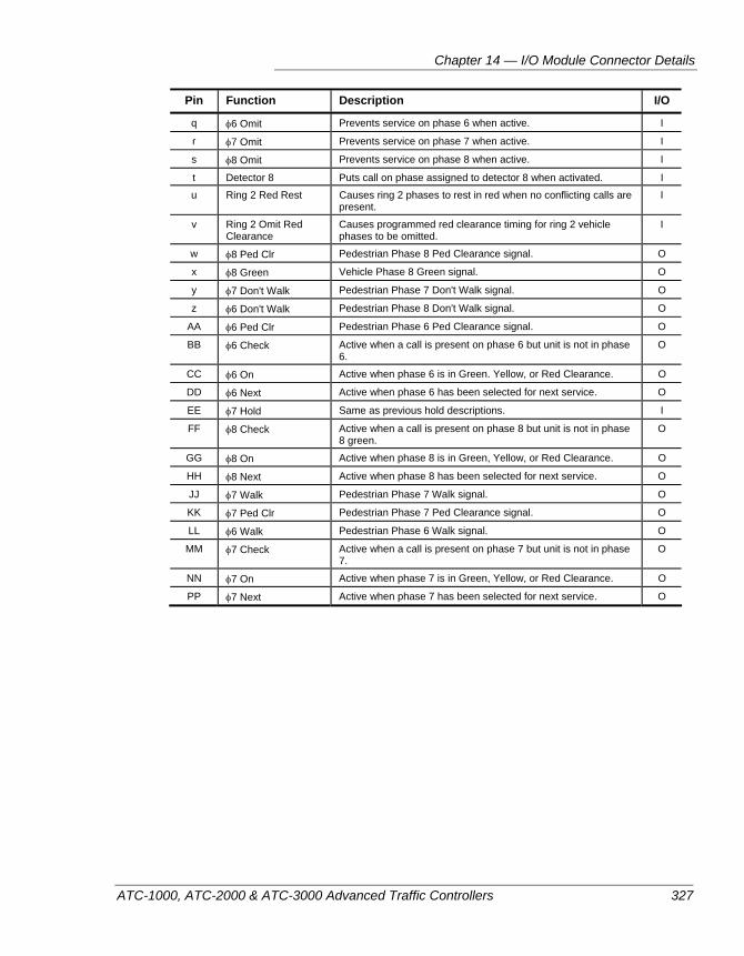
Chapter 14 — I/O Module Connector Details
ATC-1000, ATC-2000 & ATC-3000 Advanced Traffic Controllers 327
Pin Function Description I/O
q φ6 Omit Prevents service on phase 6 when active. I
r φ7 Omit Prevents service on phase 7 when active. I
s φ8 Omit Prevents service on phase 8 when active. I
t Detector 8 Puts call on phase assigned to detector 8 when activated. I
u Ring 2 Red Rest Causes ring 2 phases to rest in red when no conflicting calls are present.
I
v Ring 2 Omit Red Clearance
Causes programmed red clearance timing for ring 2 vehicle phases to be omitted.
I
w φ8 Ped Clr Pedestrian Phase 8 Ped Clearance signal. O
x φ8 Green Vehicle Phase 8 Green signal. O
y φ7 Don't Walk Pedestrian Phase 7 Don't Walk signal. O
z φ6 Don't Walk Pedestrian Phase 8 Don't Walk signal. O
AA φ6 Ped Clr Pedestrian Phase 6 Ped Clearance signal. O
BB φ6 Check Active when a call is present on phase 6 but unit is not in phase 6.
O
CC φ6 On Active when phase 6 is in Green. Yellow, or Red Clearance. O
DD φ6 Next Active when phase 6 has been selected for next service. O
EE φ7 Hold Same as previous hold descriptions. I
FF φ8 Check Active when a call is present on phase 8 but unit is not in phase 8 green.
O
GG φ8 On Active when phase 8 is in Green, Yellow, or Red Clearance. O
HH φ8 Next Active when phase 8 has been selected for next service. O
JJ φ7 Walk Pedestrian Phase 7 Walk signal. O
KK φ7 Ped Clr Pedestrian Phase 7 Ped Clearance signal. O
LL φ6 Walk Pedestrian Phase 6 Walk signal. O
MM φ7 Check Active when a call is present on phase 7 but unit is not in phase 7.
O
NN φ7 On Active when phase 7 is in Green, Yellow, or Red Clearance. O
PP φ7 Next Active when phase 7 has been selected for next service. O
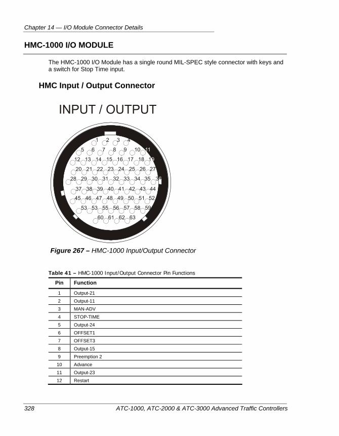
Chapter 14 — I/O Module Connector Details
328 ATC-1000, ATC-2000 & ATC-3000 Advanced Traffic Controllers
HMC-1000 I/O MODULE
The HMC-1000 I/O Module has a single round MIL-SPEC style connector with keys and a switch for Stop Time input.
HMC Input / Output Connector
Figure 267 – HMC-1000 Input/Output Connector
Table 41 – HMC-1000 Input/Output Connector Pin Functions
Pin Function
1 Output-21
2 Output-11
3 MAN-ADV
4 STOP-TIME
5 Output-24
6 OFFSET1
7 OFFSET3
8 Output-15
9 Preemption 2
10 Advance
11 Output-23
12 Restart
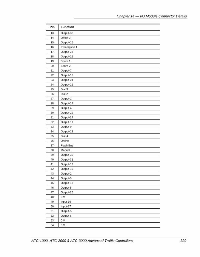
Chapter 14 — I/O Module Connector Details
ATC-1000, ATC-2000 & ATC-3000 Advanced Traffic Controllers 329
Pin Function
13 Output-32
14 Offset 2
15 Output-16
16 Preemption 1
17 Output-25
18 Output-28
19 Spare 1
20 Spare 2
21 Output-7
22 Output-18
23 Output-21
24 Output-22
25 Dial 3
26 Dial 2
27 Output-1
28 Output-14
29 Output-4
30 Output-29
31 Output-27
32 Output-17
33 Output-9
34 Output-19
35 Dial-4
36 Online
37 Flash Bus
38 Manual
39 Output-30
40 Output-31
41 Output-12
42 Output-10
43 Output-2
44 Output-3
45 Output-13
46 Output-8
47 Output-26
48 0 V
49 Input-16
50 Input-17
51 Output-5
52 Output-6
53 0 V
54 0 V
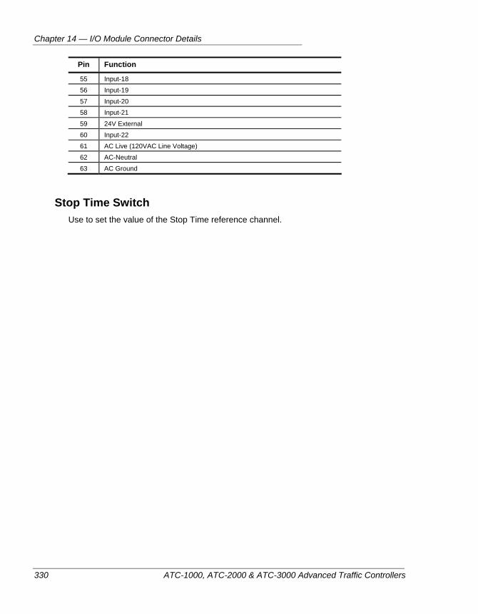
Chapter 14 — I/O Module Connector Details
330 ATC-1000, ATC-2000 & ATC-3000 Advanced Traffic Controllers
Pin Function
55 Input-18
56 Input-19
57 Input-20
58 Input-21
59 24V External
60 Input-22
61 AC Live (120VAC Line Voltage)
62 AC-Neutral
63 AC Ground
Stop Time Switch Use to set the value of the Stop Time reference channel.
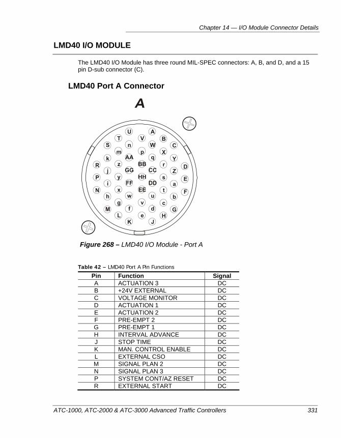
Chapter 14 — I/O Module Connector Details
ATC-1000, ATC-2000 & ATC-3000 Advanced Traffic Controllers 331
LMD40 I/O MODULE
The LMD40 I/O Module has three round MIL-SPEC connectors: A, B, and D, and a 15 pin D-sub connector (C).
LMD40 Port A Connector
Figure 268 – LMD40 I/O Module - Port A
Table 42 – LMD40 Port A Pin Functions
Pin Function Signal A ACTUATION 3 DC B +24V EXTERNAL DC C VOLTAGE MONITOR DC D ACTUATION 1 DC E ACTUATION 2 DC F PRE-EMPT 2 DC G PRE-EMPT 1 DC H INTERVAL ADVANCE DC J STOP TIME DC K MAN. CONTROL ENABLE DC L EXTERNAL CSO DC M SIGNAL PLAN 2 DC N SIGNAL PLAN 3 DC P SYSTEM CONT/AZ RESET DC R EXTERNAL START DC
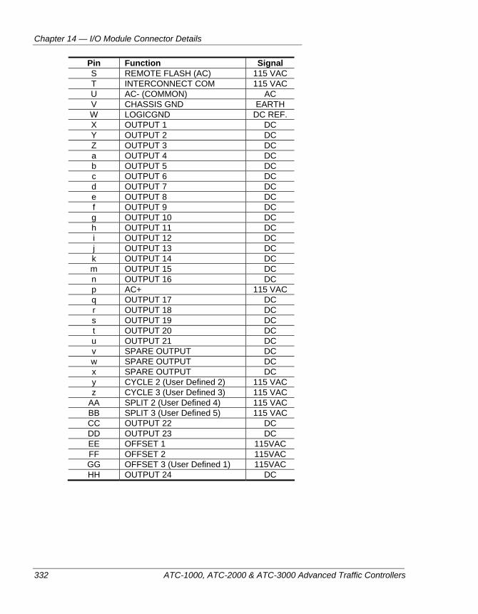
Chapter 14 — I/O Module Connector Details
332 ATC-1000, ATC-2000 & ATC-3000 Advanced Traffic Controllers
Pin Function Signal S REMOTE FLASH (AC) 115 VAC T INTERCONNECT COM 115 VAC U AC- (COMMON) AC V CHASSIS GND EARTH W LOGICGND DC REF. X OUTPUT 1 DC Y OUTPUT 2 DC Z OUTPUT 3 DC a OUTPUT 4 DC b OUTPUT 5 DC c OUTPUT 6 DC d OUTPUT 7 DC e OUTPUT 8 DC f OUTPUT 9 DC g OUTPUT 10 DC h OUTPUT 11 DC i OUTPUT 12 DC j OUTPUT 13 DC k OUTPUT 14 DC m OUTPUT 15 DC n OUTPUT 16 DC p AC+ 115 VAC q OUTPUT 17 DC r OUTPUT 18 DC s OUTPUT 19 DC t OUTPUT 20 DC u OUTPUT 21 DC v SPARE OUTPUT DC w SPARE OUTPUT DC x SPARE OUTPUT DC y CYCLE 2 (User Defined 2) 115 VAC z CYCLE 3 (User Defined 3) 115 VAC
AA SPLIT 2 (User Defined 4) 115 VAC BB SPLIT 3 (User Defined 5) 115 VAC CC OUTPUT 22 DC DD OUTPUT 23 DC EE OFFSET 1 115VAC FF OFFSET 2 115VAC GG OFFSET 3 (User Defined 1) 115VAC HH OUTPUT 24 DC
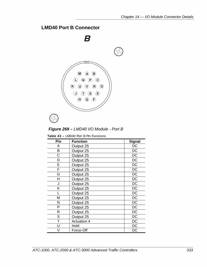
Chapter 14 — I/O Module Connector Details
ATC-1000, ATC-2000 & ATC-3000 Advanced Traffic Controllers 333
LMD40 Port B Connector
Figure 269 – LMD40 I/O Module - Port B
Table 43 – LMD40 Port B Pin Functions
Pin Function Signal A Output 25 DC B Output 25 DC C Output 25 DC D Output 25 DC E Output 25 DC F Output 25 DC G Output 25 DC H Output 25 DC J Output 25 DC K Output 25 DC L Output 25 DC M Output 25 DC N Output 25 DC P Output 25 DC R Output 25 DC S Output 25 DC T Actuation 4 DC U Hold DC V Force-Off DC
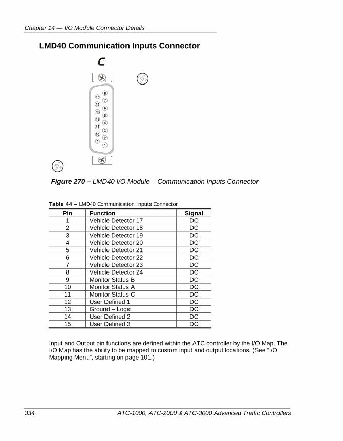
Chapter 14 — I/O Module Connector Details
334 ATC-1000, ATC-2000 & ATC-3000 Advanced Traffic Controllers
LMD40 Communication Inputs Connector
Figure 270 – LMD40 I/O Module – Communication Inputs Connector
Table 44 – LMD40 Communication Inputs Connector
Pin Function Signal 1 Vehicle Detector 17 DC 2 Vehicle Detector 18 DC 3 Vehicle Detector 19 DC 4 Vehicle Detector 20 DC 5 Vehicle Detector 21 DC 6 Vehicle Detector 22 DC 7 Vehicle Detector 23 DC 8 Vehicle Detector 24 DC 9 Monitor Status B DC 10 Monitor Status A DC 11 Monitor Status C DC 12 User Defined 1 DC 13 Ground – Logic DC 14 User Defined 2 DC 15 User Defined 3 DC
Input and Output pin functions are defined within the ATC controller by the I/O Map. The I/O Map has the ability to be mapped to custom input and output locations. (See “I/O Mapping Menu”, starting on page 101.)
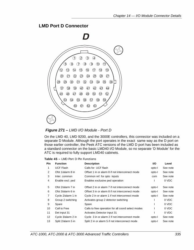
Chapter 14 — I/O Module Connector Details
ATC-1000, ATC-2000 & ATC-3000 Advanced Traffic Controllers 335
LMD Port D Connector
Figure 271 – LMD I/O Module - Port D
On the LMD 40, LMD 9200, and the 3000E controllers, this connector was included on a separate D Module. Although the port operates in the exact same way as the D port on those earlier controller, the Peek ATC versions of the LMD D port has been included as a standard connector on the basic LMD40 I/O Module, so no separate ‘D Module’ for the ATC is required to fully support LMD40 cabinets.
Table 45 – LMD Port D Pin Functions Pin Function Description I/O Level 1 UCF Flash Calls for UCF flash opto-I See note 2 Ofst 1/alarm 8 in Offset 1 in or alarm 8 if not interconnect mode opto-I See note 3 Inter. common Common ref. for opto inputs com See note 4 Enable excl. ped Enables exclusive ped operation I 0 VDC
5 Ofst 2/alarm 7 in Offset 2 in or alarm 7 if not interconnect mode opto-I See note 6 Ofst 3/alarm 6 in Offset 3 in or alarm 8 if not interconnect mode opto-I See note 7 Cycle 2/alarm 1 in Cycle 2 in or alarm 1 if not interconnect mode opto-I See note 8 Group 2 switching Activates group 2 detector switching I 0 VDC 9 Spare Spare I 0 VDC 10 Call to Free Calls to free operation for all coord select modes I 0 VDC 11 Det input 31 Activates Detector input 31 I 0 VDC 12 Cycle 3/alarm 2 in Cycle 3 in or alarm 2 if not interconnect mode opto-I See note 13 Split 2/alarm 5 in Split 2 in or alarm 5 if not interconnect mode opto-I See note
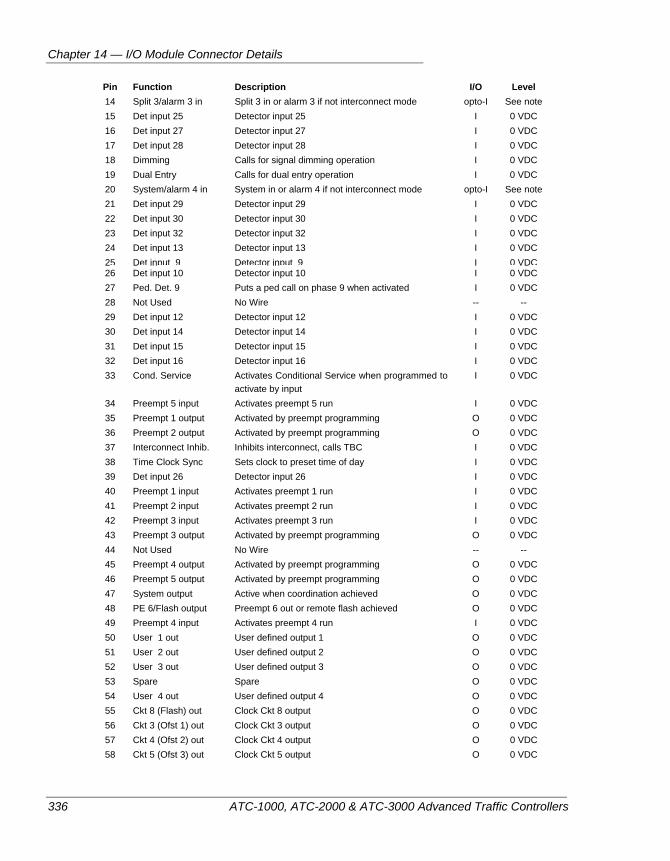
Chapter 14 — I/O Module Connector Details
336 ATC-1000, ATC-2000 & ATC-3000 Advanced Traffic Controllers
Pin Function Description I/O Level 14 Split 3/alarm 3 in Split 3 in or alarm 3 if not interconnect mode opto-I See note 15 Det input 25 Detector input 25 I 0 VDC 16 Det input 27 Detector input 27 I 0 VDC 17 Det input 28 Detector input 28 I 0 VDC 18 Dimming Calls for signal dimming operation I 0 VDC 19 Dual Entry Calls for dual entry operation I 0 VDC 20 System/alarm 4 in System in or alarm 4 if not interconnect mode opto-I See note 21 Det input 29 Detector input 29 I 0 VDC 22 Det input 30 Detector input 30 I 0 VDC 23 Det input 32 Detector input 32 I 0 VDC 24 Det input 13 Detector input 13 I 0 VDC 25 Det input 9 Detector input 9 I 0 VDC 26 Det input 10 Detector input 10 I 0 VDC 27 Ped. Det. 9 Puts a ped call on phase 9 when activated I 0 VDC 28 Not Used No Wire -- -- 29 Det input 12 Detector input 12 I 0 VDC 30 Det input 14 Detector input 14 I 0 VDC 31 Det input 15 Detector input 15 I 0 VDC 32 Det input 16 Detector input 16 I 0 VDC 33 Cond. Service Activates Conditional Service when programmed to
activate by input I 0 VDC
34 Preempt 5 input Activates preempt 5 run I 0 VDC 35 Preempt 1 output Activated by preempt programming O 0 VDC 36 Preempt 2 output Activated by preempt programming O 0 VDC 37 Interconnect Inhib. Inhibits interconnect, calls TBC I 0 VDC 38 Time Clock Sync Sets clock to preset time of day I 0 VDC 39 Det input 26 Detector input 26 I 0 VDC 40 Preempt 1 input Activates preempt 1 run I 0 VDC 41 Preempt 2 input Activates preempt 2 run I 0 VDC 42 Preempt 3 input Activates preempt 3 run I 0 VDC 43 Preempt 3 output Activated by preempt programming O 0 VDC 44 Not Used No Wire -- -- 45 Preempt 4 output Activated by preempt programming O 0 VDC 46 Preempt 5 output Activated by preempt programming O 0 VDC 47 System output Active when coordination achieved O 0 VDC 48 PE 6/Flash output Preempt 6 out or remote flash achieved O 0 VDC 49 Preempt 4 input Activates preempt 4 run I 0 VDC 50 User 1 out User defined output 1 O 0 VDC 51 User 2 out User defined output 2 O 0 VDC 52 User 3 out User defined output 3 O 0 VDC 53 Spare Spare O 0 VDC 54 User 4 out User defined output 4 O 0 VDC 55 Ckt 8 (Flash) out Clock Ckt 8 output O 0 VDC 56 Ckt 3 (Ofst 1) out Clock Ckt 3 output O 0 VDC 57 Ckt 4 (Ofst 2) out Clock Ckt 4 output O 0 VDC 58 Ckt 5 (Ofst 3) out Clock Ckt 5 output O 0 VDC
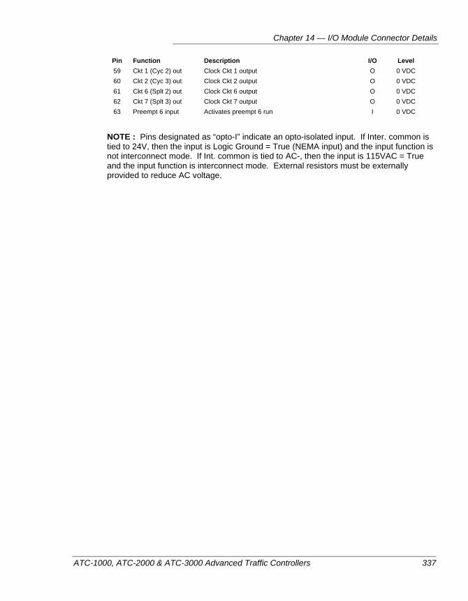
Chapter 14 — I/O Module Connector Details
ATC-1000, ATC-2000 & ATC-3000 Advanced Traffic Controllers 337
Pin Function Description I/O Level 59 Ckt 1 (Cyc 2) out Clock Ckt 1 output O 0 VDC 60 Ckt 2 (Cyc 3) out Clock Ckt 2 output O 0 VDC 61 Ckt 6 (Splt 2) out Clock Ckt 6 output O 0 VDC 62 Ckt 7 (Splt 3) out Clock Ckt 7 output O 0 VDC 63 Preempt 6 input Activates preempt 6 run I 0 VDC
NOTE : Pins designated as “opto-I” indicate an opto-isolated input. If Inter. common is tied to 24V, then the input is Logic Ground = True (NEMA input) and the input function is not interconnect mode. If Int. common is tied to AC-, then the input is 115VAC = True and the input function is interconnect mode. External resistors must be externally provided to reduce AC voltage.
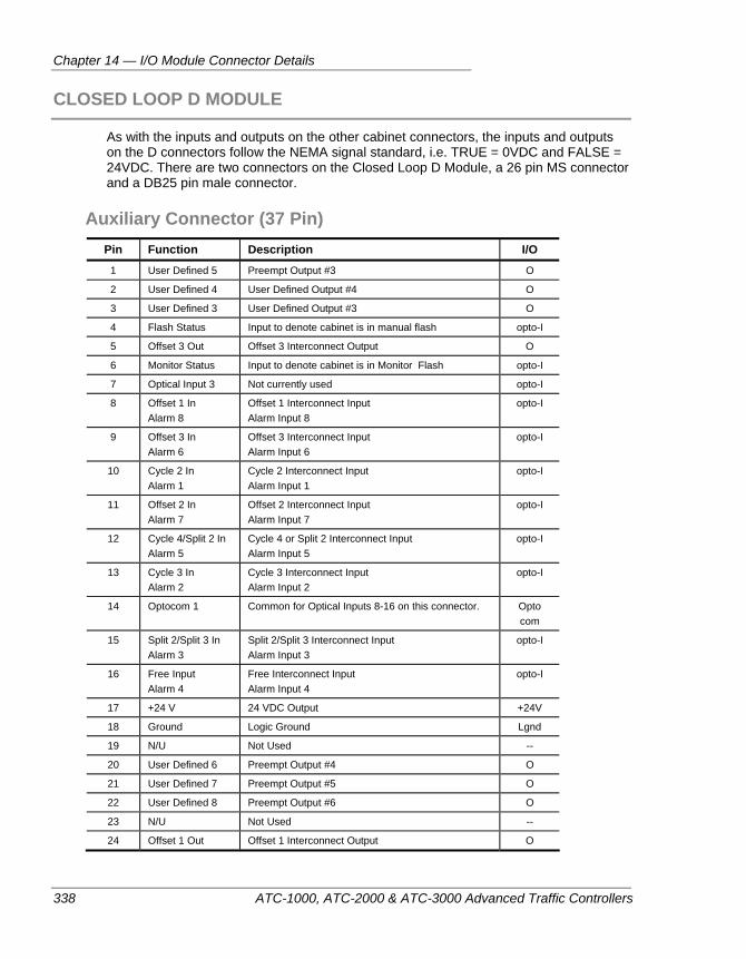
Chapter 14 — I/O Module Connector Details
338 ATC-1000, ATC-2000 & ATC-3000 Advanced Traffic Controllers
CLOSED LOOP D MODULE
As with the inputs and outputs on the other cabinet connectors, the inputs and outputs on the D connectors follow the NEMA signal standard, i.e. TRUE = 0VDC and FALSE = 24VDC. There are two connectors on the Closed Loop D Module, a 26 pin MS connector and a DB25 pin male connector.
Auxiliary Connector (37 Pin) Pin Function Description I/O
1 User Defined 5 Preempt Output #3 O
2 User Defined 4 User Defined Output #4 O
3 User Defined 3 User Defined Output #3 O
4 Flash Status Input to denote cabinet is in manual flash opto-I
5 Offset 3 Out Offset 3 Interconnect Output O
6 Monitor Status Input to denote cabinet is in Monitor Flash opto-I
7 Optical Input 3 Not currently used opto-I
8 Offset 1 In Alarm 8
Offset 1 Interconnect Input Alarm Input 8
opto-I
9 Offset 3 In Alarm 6
Offset 3 Interconnect Input Alarm Input 6
opto-I
10 Cycle 2 In Alarm 1
Cycle 2 Interconnect Input Alarm Input 1
opto-I
11 Offset 2 In Alarm 7
Offset 2 Interconnect Input Alarm Input 7
opto-I
12 Cycle 4/Split 2 In Alarm 5
Cycle 4 or Split 2 Interconnect Input Alarm Input 5
opto-I
13 Cycle 3 In Alarm 2
Cycle 3 Interconnect Input Alarm Input 2
opto-I
14 Optocom 1 Common for Optical Inputs 8-16 on this connector. Opto com
15 Split 2/Split 3 In Alarm 3
Split 2/Split 3 Interconnect Input Alarm Input 3
opto-I
16 Free Input Alarm 4
Free Interconnect Input Alarm Input 4
opto-I
17 +24 V 24 VDC Output +24V
18 Ground Logic Ground Lgnd
19 N/U Not Used --
20 User Defined 6 Preempt Output #4 O
21 User Defined 7 Preempt Output #5 O
22 User Defined 8 Preempt Output #6 O
23 N/U Not Used --
24 Offset 1 Out Offset 1 Interconnect Output O
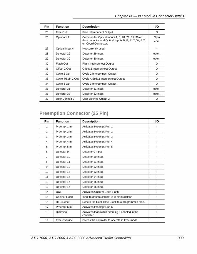
Chapter 14 — I/O Module Connector Details
ATC-1000, ATC-2000 & ATC-3000 Advanced Traffic Controllers 339
Pin Function Description I/O 25 Free Out Free Interconnect Output O
26 Optocom 2 Common for Optical Inputs 4, 6, 28, 29, 35, 36 on this connector and Optical Inputs B, P, R, T, W, & X on Coord Connector.
Opto com
27 Optical Input 4 Not currently used --
28 Detector 29 Detector 29 Input opto-I
29 Detector 30 Detector 30 Input opto-I
30 Flash Out Flash Interconnect Output O
31 Offset 2 Out Offset 2 Interconnect Output O
32 Cycle 2 Out Cycle 2 Interconnect Output O
33 Cycle 4/Split 2 Out Cycle 4/Split 2 Interconnect Output O
34 Cycle 3 Out Cycle 3 Interconnect Output O
35 Detector 31 Detector 31 Input opto-I
36 Detector 32 Detector 32 Input opto-I
37 User Defined 2 User Defined Output 2 O
Preemption Connector (25 Pin) Pin Function Description I/O
1 Preempt 1 In Activates Preempt Run 1 I
2 Preempt 2 In Activates Preempt Run 2 I
3 Preempt 3 In Activates Preempt Run 3 I
4 Preempt 4 In Activates Preempt Run 4 I
5 Preempt 5 In Activates Preempt Run 5 I
6 Detector 9 Detector 9 Input I
7 Detector 10 Detector 10 Input I
8 Detector 11 Detector 11 Input I
9 Detector 12 Detector 12 Input I
10 Detector 13 Detector 13 Input I
11 Detector 14 Detector 14 Input I
12 Detector 15 Detector 15 Input I
13 Detector 16 Detector 16 Input I
14 UCF Activates Uniform Code Flash I
15 Cabinet Flash Input to denote cabinet is in manual flash I
16 RTC Reset Resets the Real-Time Clock to a programmed time. I
17 Preempt 6 In Activates Preempt Run 6 I
18 Dimming Activates loadswitch dimming if enabled in the controller.
I
19 Free Override Forces the controller to operate in Free mode. I
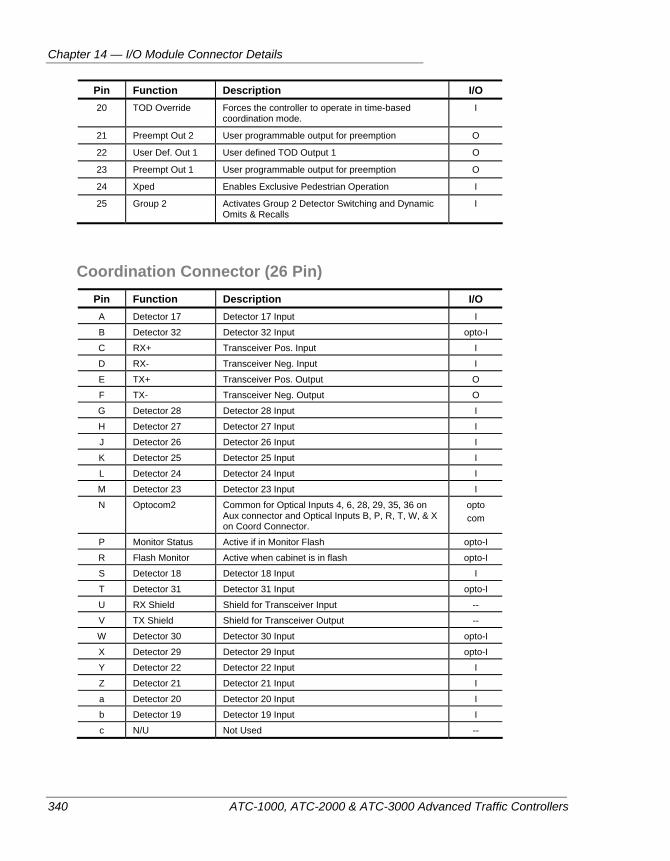
Chapter 14 — I/O Module Connector Details
340 ATC-1000, ATC-2000 & ATC-3000 Advanced Traffic Controllers
Pin Function Description I/O 20 TOD Override Forces the controller to operate in time-based
coordination mode. I
21 Preempt Out 2 User programmable output for preemption O
22 User Def. Out 1 User defined TOD Output 1 O
23 Preempt Out 1 User programmable output for preemption O
24 Xped Enables Exclusive Pedestrian Operation I
25 Group 2 Activates Group 2 Detector Switching and Dynamic Omits & Recalls
I
Coordination Connector (26 Pin) Pin Function Description I/O A Detector 17 Detector 17 Input I
B Detector 32 Detector 32 Input opto-I
C RX+ Transceiver Pos. Input I
D RX- Transceiver Neg. Input I
E TX+ Transceiver Pos. Output O
F TX- Transceiver Neg. Output O
G Detector 28 Detector 28 Input I
H Detector 27 Detector 27 Input I
J Detector 26 Detector 26 Input I
K Detector 25 Detector 25 Input I
L Detector 24 Detector 24 Input I
M Detector 23 Detector 23 Input I
N Optocom2 Common for Optical Inputs 4, 6, 28, 29, 35, 36 on Aux connector and Optical Inputs B, P, R, T, W, & X on Coord Connector.
opto com
P Monitor Status Active if in Monitor Flash opto-I
R Flash Monitor Active when cabinet is in flash opto-I
S Detector 18 Detector 18 Input I
T Detector 31 Detector 31 Input opto-I
U RX Shield Shield for Transceiver Input --
V TX Shield Shield for Transceiver Output --
W Detector 30 Detector 30 Input opto-I
X Detector 29 Detector 29 Input opto-I
Y Detector 22 Detector 22 Input I
Z Detector 21 Detector 21 Input I
a Detector 20 Detector 20 Input I
b Detector 19 Detector 19 Input I
c N/U Not Used --
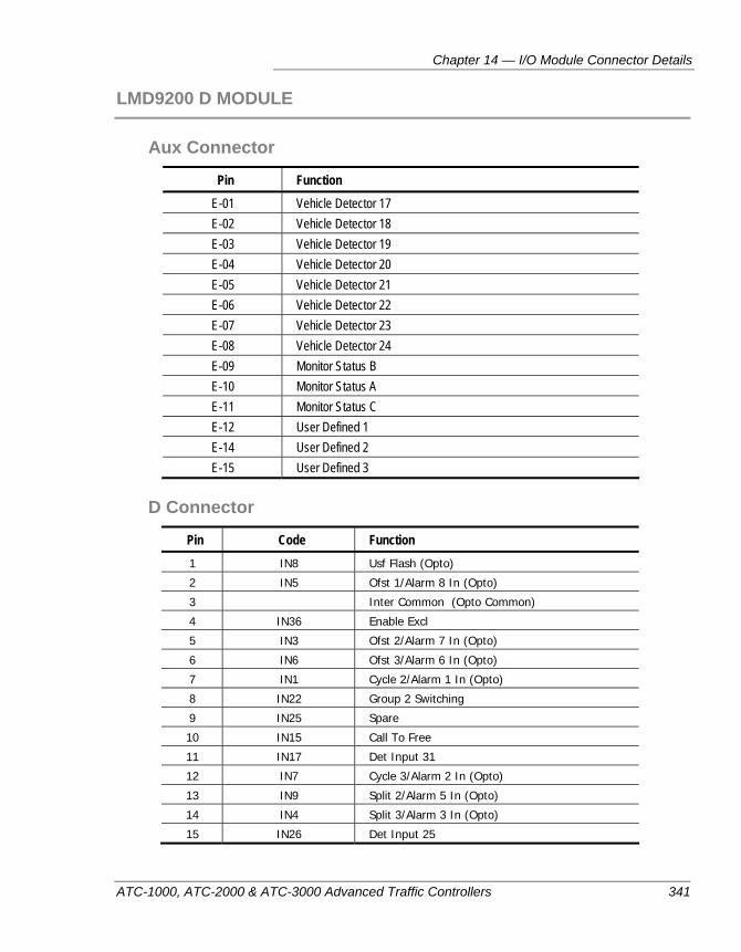
Chapter 14 — I/O Module Connector Details
ATC-1000, ATC-2000 & ATC-3000 Advanced Traffic Controllers 341
LMD9200 D MODULE
Aux Connector
Pin Function E-01 Vehicle Detector 17 E-02 Vehicle Detector 18 E-03 Vehicle Detector 19 E-04 Vehicle Detector 20 E-05 Vehicle Detector 21 E-06 Vehicle Detector 22 E-07 Vehicle Detector 23 E-08 Vehicle Detector 24 E-09 Monitor Status B E-10 Monitor Status A E-11 Monitor Status C E-12 User Defined 1 E-14 User Defined 2 E-15 User Defined 3
D Connector
Pin Code Function 1 IN8 Usf Flash (Opto)
2 IN5 Ofst 1/Alarm 8 In (Opto)
3 Inter Common (Opto Common)
4 IN36 Enable Excl
5 IN3 Ofst 2/Alarm 7 In (Opto)
6 IN6 Ofst 3/Alarm 6 In (Opto)
7 IN1 Cycle 2/Alarm 1 In (Opto)
8 IN22 Group 2 Switching
9 IN25 Spare
10 IN15 Call To Free
11 IN17 Det Input 31
12 IN7 Cycle 3/Alarm 2 In (Opto)
13 IN9 Split 2/Alarm 5 In (Opto)
14 IN4 Split 3/Alarm 3 In (Opto)
15 IN26 Det Input 25
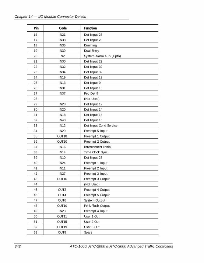
Chapter 14 — I/O Module Connector Details
342 ATC-1000, ATC-2000 & ATC-3000 Advanced Traffic Controllers
Pin Code Function 16 IN21 Det Input 27
17 IN38 Det Input 28
18 IN35 Dimming
19 IN39 Dual Entry
20 IN2 System Alarm 4 In (Opto)
21 IN30 Det Input 29
22 IN32 Det Input 30
23 IN34 Det Input 32
24 IN19 Det Input 13
25 IN13 Det Input 9
26 IN31 Det Input 10
27 IN37 Ped Det 9
28 (Not Used)
29 IN28 Det Input 12
30 IN20 Det Input 14
31 IN18 Det Input 15
32 IN40 Det Input 16
33 IN12 Det Input Cond Service
34 IN29 Preempt 5 Input
35 OUT18 Preempt 1 Output
36 OUT20 Preempt 2 Output
37 IN16 Interconnect Inhib
38 IN14 Time Clock Sync
39 IN10 Det Input 26
40 IN24 Preempt 1 Input
41 IN11 Preempt 2 Input
42 IN27 Preempt 3 Input
43 OUT16 Preempt 3 Output
44 (Not Used)
45 OUT2 Preempt 4 Output
46 OUT4 Preempt 5 Output
47 OUT6 System Output
48 OUT10 Pe 6/Flash Output
49 IN23 Preempt 4 Input
50 OUT11 User 1 Out
51 OUT15 User 2 Out
52 OUT19 User 3 Out
53 OUT8 Spare
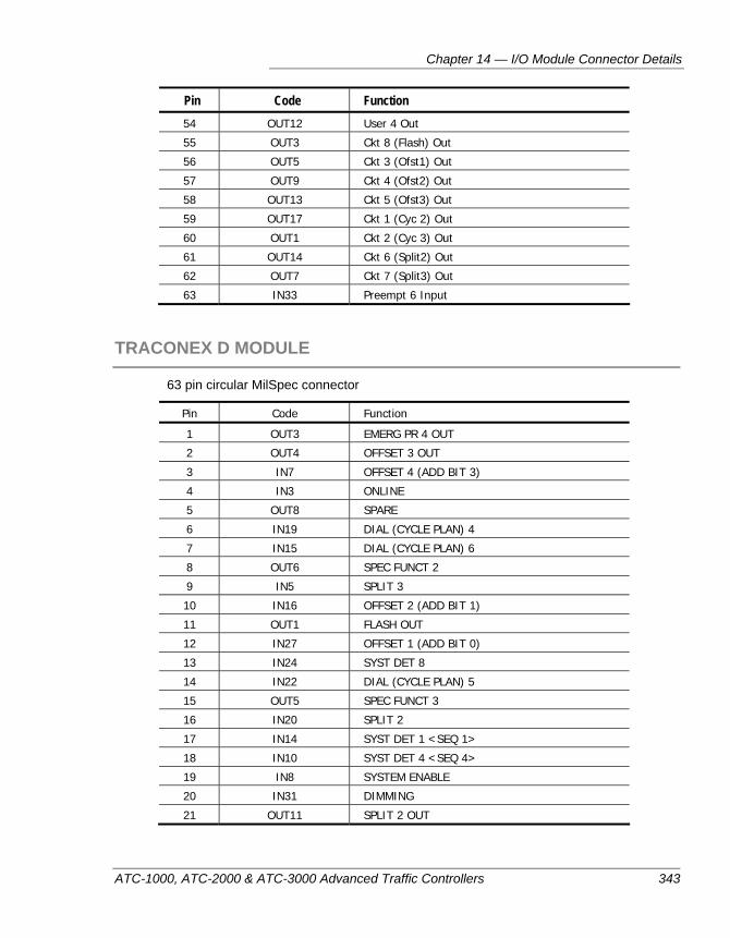
Chapter 14 — I/O Module Connector Details
ATC-1000, ATC-2000 & ATC-3000 Advanced Traffic Controllers 343
Pin Code Function 54 OUT12 User 4 Out
55 OUT3 Ckt 8 (Flash) Out
56 OUT5 Ckt 3 (Ofst1) Out
57 OUT9 Ckt 4 (Ofst2) Out
58 OUT13 Ckt 5 (Ofst3) Out
59 OUT17 Ckt 1 (Cyc 2) Out
60 OUT1 Ckt 2 (Cyc 3) Out
61 OUT14 Ckt 6 (Split2) Out
62 OUT7 Ckt 7 (Split3) Out
63 IN33 Preempt 6 Input
TRACONEX D MODULE
63 pin circular MilSpec connector
Pin Code Function
1 OUT3 EMERG PR 4 OUT
2 OUT4 OFFSET 3 OUT
3 IN7 OFFSET 4 (ADD BIT 3)
4 IN3 ONLINE
5 OUT8 SPARE
6 IN19 DIAL (CYCLE PLAN) 4
7 IN15 DIAL (CYCLE PLAN) 6
8 OUT6 SPEC FUNCT 2
9 IN5 SPLIT 3
10 IN16 OFFSET 2 (ADD BIT 1)
11 OUT1 FLASH OUT
12 IN27 OFFSET 1 (ADD BIT 0)
13 IN24 SYST DET 8
14 IN22 DIAL (CYCLE PLAN) 5
15 OUT5 SPEC FUNCT 3
16 IN20 SPLIT 2
17 IN14 SYST DET 1 <SEQ 1>
18 IN10 SYST DET 4 <SEQ 4>
19 IN8 SYSTEM ENABLE
20 IN31 DIMMING
21 OUT11 SPLIT 2 OUT
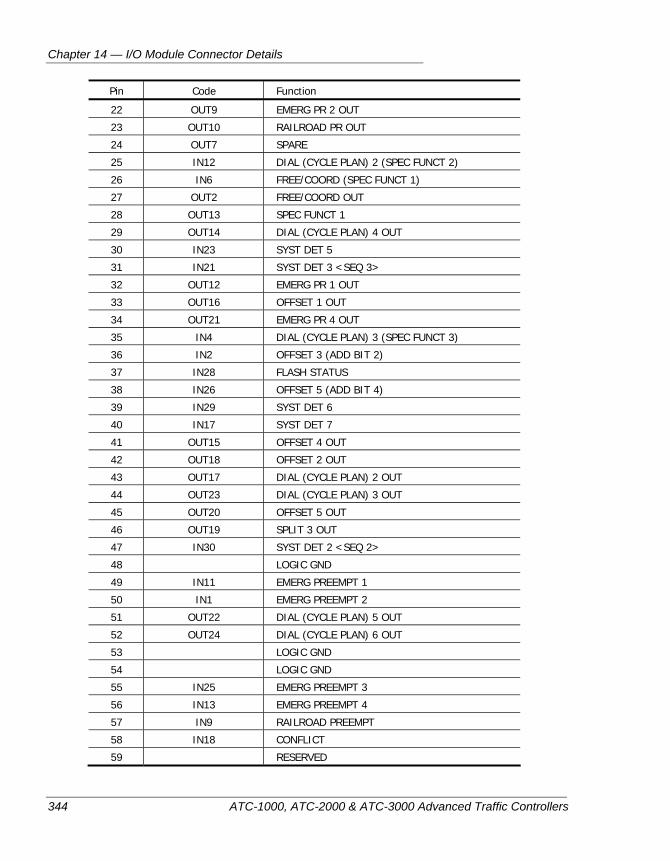
Chapter 14 — I/O Module Connector Details
344 ATC-1000, ATC-2000 & ATC-3000 Advanced Traffic Controllers
Pin Code Function
22 OUT9 EMERG PR 2 OUT
23 OUT10 RAILROAD PR OUT
24 OUT7 SPARE
25 IN12 DIAL (CYCLE PLAN) 2 (SPEC FUNCT 2)
26 IN6 FREE/COORD (SPEC FUNCT 1)
27 OUT2 FREE/COORD OUT
28 OUT13 SPEC FUNCT 1
29 OUT14 DIAL (CYCLE PLAN) 4 OUT
30 IN23 SYST DET 5
31 IN21 SYST DET 3 <SEQ 3>
32 OUT12 EMERG PR 1 OUT
33 OUT16 OFFSET 1 OUT
34 OUT21 EMERG PR 4 OUT
35 IN4 DIAL (CYCLE PLAN) 3 (SPEC FUNCT 3)
36 IN2 OFFSET 3 (ADD BIT 2)
37 IN28 FLASH STATUS
38 IN26 OFFSET 5 (ADD BIT 4)
39 IN29 SYST DET 6
40 IN17 SYST DET 7
41 OUT15 OFFSET 4 OUT
42 OUT18 OFFSET 2 OUT
43 OUT17 DIAL (CYCLE PLAN) 2 OUT
44 OUT23 DIAL (CYCLE PLAN) 3 OUT
45 OUT20 OFFSET 5 OUT
46 OUT19 SPLIT 3 OUT
47 IN30 SYST DET 2 <SEQ 2>
48 LOGIC GND
49 IN11 EMERG PREEMPT 1
50 IN1 EMERG PREEMPT 2
51 OUT22 DIAL (CYCLE PLAN) 5 OUT
52 OUT24 DIAL (CYCLE PLAN) 6 OUT
53 LOGIC GND
54 LOGIC GND
55 IN25 EMERG PREEMPT 3
56 IN13 EMERG PREEMPT 4
57 IN9 RAILROAD PREEMPT
58 IN18 CONFLICT
59 RESERVED
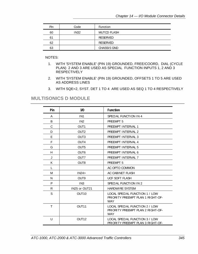
Chapter 14 — I/O Module Connector Details
ATC-1000, ATC-2000 & ATC-3000 Advanced Traffic Controllers 345
Pin Code Function
60 IN32 MUTCD FLASH
61 RESERVED
62 RESERVED
63 CHASSIS GND
NOTES:
1. WITH 'SYSTEM ENABLE' (PIN 19) GROUNDED, FREE/COORD, DIAL (CYCLE PLAN) 2 AND 3 ARE USED AS SPECIAL FUNCTION INPUTS 1, 2 AND 3 RESPECTIVELY
2. WITH 'SYSTEM ENABLE' (PIN 19) GROUNDED, OFFSETS 1 TO 5 ARE USED AS ADDRESS LINES
3. WITH SQE=2, SYST. DET 1 TO 4 ARE USED AS SEQ 1 TO 4 RESPECTIVELY
MULTISONICS D MODULE
Pin I/O Function A IN1 SPECIAL FUNCTION IN 4
B IN2 PREEMPT 5
C OUT1 PREEMPT INTERVAL 1
D OUT2 PREEMPT INTERVAL 2
E OUT3 PREEMPT INTERVAL 3
F OUT4 PREEMPT INTERVAL 4
G OUT5 PREEMPT INTERVAL 5
H OUT6 PREEMPT INTERVAL 6
J OUT7 PREEMPT INTERVAL 7
K OUT8 PREEMPT 5
L AC OPTO COMMON
M IN24> AC CABINET FLASH
N OUT9 UCF SOFT FLASH
P IN3 SPECIAL FUNCTION IN 2
R IN25 or OUT21 HARDWIRE SYSTEM
S OUT10 LOCAL SPECIAL FUNCTION 1 / LOW PRIORITY PREEMPT PLAN 1 RIGHT-OF-WAY
T OUT11 LOCAL SPECIAL FUNCTION 2 / LOW PRIORITY PREEMPT PLAN 2 RIGHT-OF-WAY
U OUT12 LOCAL SPECIAL FUNCTION 3 / LOW PRIORITY PREEMPT PLAN 3 RIGHT-OF-
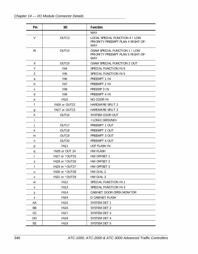
Chapter 14 — I/O Module Connector Details
346 ATC-1000, ATC-2000 & ATC-3000 Advanced Traffic Controllers
Pin I/O Function WAY
V OUT13 LOCAL SPECIAL FUNCTION 4 / LOW PRIORITY PREEMPT PLAN 4 RIGHT-OF-WAY
W OUT14 OSAM SPECIAL FUNCTION 1 / LOW PRIORITY PREEMPT PLAN 5 RIGHT-OF-WAY
X OUT15 OSAM SPECIAL FUNCTION 2 OUT
Y IN4 SPECIAL FUNCTION IN 6
Z IN5 SPECIAL FUNCTION IN 5
a IN6 PREEMPT 1 IN
b IN7 PREEMPT 2 IN
c IN8 PREEMP 3 IN
d IN9 PREEMPT 4 IN
e IN10 NO COOR IN
f IN26 or OUT22 HARDWIRE SPLIT 2
g IN27 or OUT23 HARDWIRE SPLIT 3
h OUT16 SYSTEM COOR OUT
i <LOGIC GROUND>
j OUT17 PREEMPT 1 OUT
k OUT18 PREEMPT 2 OUT
m OUT19 PREEMPT 3 OUT
n OUT20 PREEMPT 4 OUT
p IN11 UCF FLASH IN
q IN26 or OUT 24 HW FLASH
r IN27 or *OUT25 HW OFFSET 1
s IN28 or *OUT26 HW OFFSET 2
t IN29 or *OUT27 HW OFFSET 3
u IN30 or *OUT28 HW DIAL 2
v IN31 or *OUT29 HW DIAL 3
w IN12 SPECIAL FUNCTION IN 1
x IN13 SPECIAL FUNCTION IN 3
y IN14 CABINET DOOR OPEN MONITOR
z IN24 D CABINET FLASH
AA IN15 SYSTEM DET 1
BB IN16 SYSTEM DET 2
CC IN17 SYSTEM DET 3
DD IN18 SYSTEM DET 4
EE IN19 SYSTEM DET 5
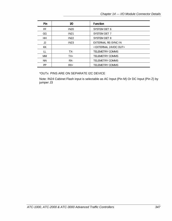
Chapter 14 — I/O Module Connector Details
ATC-1000, ATC-2000 & ATC-3000 Advanced Traffic Controllers 347
Pin I/O Function FF IN20 SYSTEM DET 6
GG IN21 SYSTEM DET 7
HH IN22 SYSTEM DET 8
JJ IN23 EXTERNAL RE-SYNC IN
KK <EXTERNAL 24VDC OUT>
LL TX- TELEMETRY COMMS
MM TX+ TELEMETRY COMMS
NN RX- TELEMETRY COMMS
PP RX+ TELEMETRY COMMS
*OUTx PINS ARE ON SEPARATE I2C DEVICE
Note: IN24 Cabinet Flash input is selectable as AC Input (Pin M) Or DC Input (Pin Z) by jumper J3

Chapter 14 — I/O Module Connector Details
348 ATC-1000, ATC-2000 & ATC-3000 Advanced Traffic Controllers
Glossary
ATC-1000, ATC-2000 & ATC-3000 Advanced Traffic Controllers 349
Glossary
3000E — A traffic controller produced by Peek Traffic Corporation.
AC — Alternating Current
Actuated — Identifies a type of controller which responds to calling signals generated by the actions of either vehicles or pedestrians. See also Semi-actuated and Fully-actuated.
Adaptive Split Control — A means of intersection split selection based on vehicular activity.
ADC — Analog-to-Digital Converter
ACD, Advance Call Detector — A detector located a considerable distance upstream from an intersection which calls the green to that approach.
AW, Advance Warning — A per-movement output used to give advance notice of an upcoming yellow or red indication. Typically used at hidden intersections with “prepare to stop” indicators.
ASCII — American standard code of information interchange. A standard code that assigns eight-bit codes to individual alphanumeric characters.
ASTC — Advanced Solid State Traffic Controller: the name given to a controller design specified by New York City DOT. This acronym was chosen to distinguish it from the more general ATC standards development program. The ATC-1000 controller is an ASTC controller.
ATC — Advanced Traffic Controller, a design developed per the ATC standards development program of the State of California and the Federal Highway Administration. Requires the controller to have a separate engine board and run the Linux operating system. The ATC-1000 controller is not an ATC controller.
Auto/Manual Switch — A cabinet switch, when operated, discontinues normal signal operation and permits manual operation.
AWG — American Wire Gauge – used to identify wire thickness
Backplane — A printed circuit connector interface board, typically with no active or passive components. However, the use of passive components is accepted for most applications.
Back Panel — A board within the controller cabinet upon which are mounted field terminals, fuse receptacles or circuit breakers, and other components of controller operation not included in the controller unit itself, or its ancillary devices. Such back panels are typical in older traffic control cabinets.
Barrier — A logical term to describe a line of compatibility in a multi-ring signal plan in which all rings are interlocked. Barriers assure that there will be no concurrent selection and timing of conflicting phases for traffic phases on different rings.
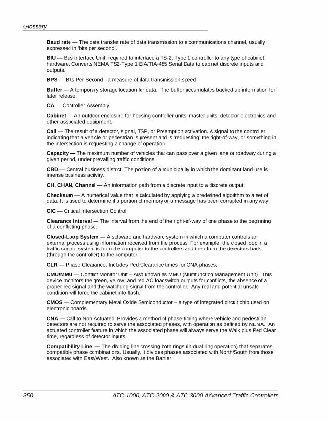
Glossary
350 ATC-1000, ATC-2000 & ATC-3000 Advanced Traffic Controllers
Baud rate — The data transfer rate of data transmission to a communications channel, usually expressed in ‘bits per second’.
BIU — Bus Interface Unit, required to interface a TS-2, Type 1 controller to any type of cabinet hardware. Converts NEMA TS2-Type 1 EIA/TIA-485 Serial Data to cabinet discrete inputs and outputs.
BPS — Bits Per Second - a measure of data transmission speed
Buffer — A temporary storage location for data. The buffer accumulates backed-up information for later release.
CA — Controller Assembly
Cabinet — An outdoor enclosure for housing controller units, master units, detector electronics and other associated equipment.
Call — The result of a detector, signal, TSP, or Preemption activation. A signal to the controller indicating that a vehicle or pedestrian is present and is ‘requesting’ the right-of-way, or something in the intersection is requesting a change of operation.
Capacity — The maximum number of vehicles that can pass over a given lane or roadway during a given period, under prevailing traffic conditions.
CBD — Central business district. The portion of a municipality in which the dominant land use is intense business activity.
CH, CHAN, Channel — An information path from a discrete input to a discrete output.
Checksum — A numerical value that is calculated by applying a predefined algorithm to a set of data. It is used to determine if a portion of memory or a message has been corrupted in any way.
CIC — Critical Intersection Control
Clearance Interval — The interval from the end of the right-of-way of one phase to the beginning of a conflicting phase.
Closed-Loop System — A software and hardware system in which a computer controls an external process using information received from the process. For example, the closed loop in a traffic control system is from the computer to the controllers and then from the detectors back (through the controller) to the computer.
CLR — Phase Clearance. Includes Ped Clearance times for CNA phases.
CMU/MMU — Conflict Monitor Unit – Also known as MMU (Multifunction Management Unit). This device monitors the green, yellow, and red AC loadswitch outputs for conflicts, the absence of a proper red signal and the watchdog signal from the controller. Any real and potential unsafe condition will force the cabinet into flash.
CMOS — Complementary Metal Oxide Semiconductor – a type of integrated circuit chip used on electronic boards.
CNA — Call to Non-Actuated. Provides a method of phase timing where vehicle and pedestrian detectors are not required to serve the associated phases, with operation as defined by NEMA. An actuated controller feature in which the associated phase will always serve the Walk plus Ped Clear time, regardless of detector inputs.
Compatibility Line — The dividing line crossing both rings (in dual ring operation) that separates compatible phase combinations. Usually, it divides phases associated with North/South from those associated with East/West. Also known as the Barrier.
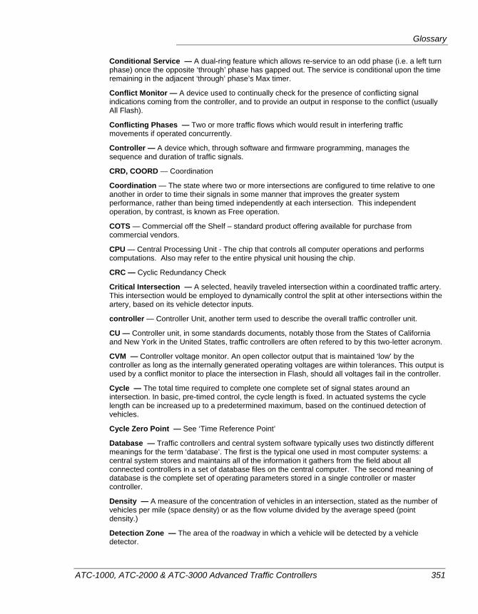
Glossary
ATC-1000, ATC-2000 & ATC-3000 Advanced Traffic Controllers 351
Conditional Service — A dual-ring feature which allows re-service to an odd phase (i.e. a left turn phase) once the opposite ‘through’ phase has gapped out. The service is conditional upon the time remaining in the adjacent ‘through’ phase’s Max timer.
Conflict Monitor — A device used to continually check for the presence of conflicting signal indications coming from the controller, and to provide an output in response to the conflict (usually All Flash).
Conflicting Phases — Two or more traffic flows which would result in interfering traffic movements if operated concurrently.
Controller — A device which, through software and firmware programming, manages the sequence and duration of traffic signals.
CRD, COORD — Coordination
Coordination — The state where two or more intersections are configured to time relative to one another in order to time their signals in some manner that improves the greater system performance, rather than being timed independently at each intersection. This independent operation, by contrast, is known as Free operation.
COTS — Commercial off the Shelf – standard product offering available for purchase from commercial vendors.
CPU — Central Processing Unit - The chip that controls all computer operations and performs computations. Also may refer to the entire physical unit housing the chip.
CRC — Cyclic Redundancy Check
Critical Intersection — A selected, heavily traveled intersection within a coordinated traffic artery. This intersection would be employed to dynamically control the split at other intersections within the artery, based on its vehicle detector inputs.
controller — Controller Unit, another term used to describe the overall traffic controller unit.
CU — Controller unit, in some standards documents, notably those from the States of California and New York in the United States, traffic controllers are often refered to by this two-letter acronym.
CVM — Controller voltage monitor. An open collector output that is maintained ‘low’ by the controller as long as the internally generated operating voltages are within tolerances. This output is used by a conflict monitor to place the intersection in Flash, should all voltages fail in the controller.
Cycle — The total time required to complete one complete set of signal states around an intersection. In basic, pre-timed control, the cycle length is fixed. In actuated systems the cycle length can be increased up to a predetermined maximum, based on the continued detection of vehicles.
Cycle Zero Point — See ‘Time Reference Point’
Database — Traffic controllers and central system software typically uses two distinctly different meanings for the term ‘database’. The first is the typical one used in most computer systems: a central system stores and maintains all of the information it gathers from the field about all connected controllers in a set of database files on the central computer. The second meaning of database is the complete set of operating parameters stored in a single controller or master controller.
Density — A measure of the concentration of vehicles in an intersection, stated as the number of vehicles per mile (space density) or as the flow volume divided by the average speed (point density.)
Detection Zone — The area of the roadway in which a vehicle will be detected by a vehicle detector.
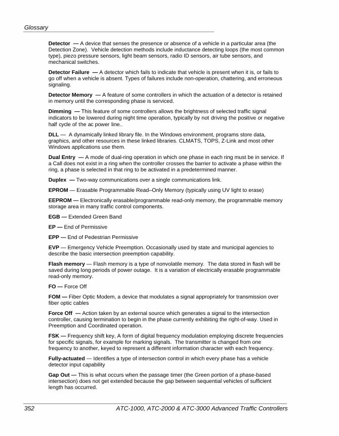
Glossary
352 ATC-1000, ATC-2000 & ATC-3000 Advanced Traffic Controllers
Detector — A device that senses the presence or absence of a vehicle in a particular area (the Detection Zone). Vehicle detection methods include inductance detecting loops (the most common type), piezo pressure sensors, light beam sensors, radio ID sensors, air tube sensors, and mechanical switches.
Detector Failure — A detector which fails to indicate that vehicle is present when it is, or fails to go off when a vehicle is absent. Types of failures include non-operation, chattering, and erroneous signaling.
Detector Memory — A feature of some controllers in which the actuation of a detector is retained in memory until the corresponding phase is serviced.
Dimming — This feature of some controllers allows the brightness of selected traffic signal indicators to be lowered during night time operation, typically by not driving the positive or negative half cycle of the ac power line..
DLL — A dynamically linked library file. In the Windows environment, programs store data, graphics, and other resources in these linked libraries. CLMATS, TOPS, Z-Link and most other Windows applications use them.
Dual Entry — A mode of dual-ring operation in which one phase in each ring must be in service. If a Call does not exist in a ring when the controller crosses the barrier to activate a phase within the ring, a phase is selected in that ring to be activated in a predetermined manner.
Duplex — Two-way communications over a single communications link.
EPROM — Erasable Programmable Read–Only Memory (typically using UV light to erase)
EEPROM — Electronically erasable/programmable read-only memory, the programmable memory storage area in many traffic control components.
EGB — Extended Green Band
EP — End of Permissive
EPP — End of Pedestrian Permissive
EVP — Emergency Vehicle Preemption. Occasionally used by state and municipal agencies to describe the basic intersection preemption capability.
Flash memory — Flash memory is a type of nonvolatile memory. The data stored in flash will be saved during long periods of power outage. It is a variation of electrically erasable programmable read-only memory.
FO — Force Off
FOM — Fiber Optic Modem, a device that modulates a signal appropriately for transmission over fiber optic cables
Force Off — Action taken by an external source which generates a signal to the intersection controller, causing termination to begin in the phase currently exhibiting the right-of-way. Used in Preemption and Coordinated operation.
FSK — Frequency shift key, A form of digital frequency modulation employing discrete frequencies for specific signals, for example for marking signals. The transmitter is changed from one frequency to another, keyed to represent a different information character with each frequency.
Fully-actuated — Identifies a type of intersection control in which every phase has a vehicle detector input capability
Gap Out — This is what occurs when the passage timer (the Green portion of a phase-based intersection) does not get extended because the gap between sequential vehicles of sufficient length has occurred.
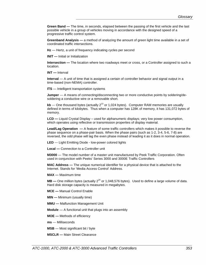
Glossary
ATC-1000, ATC-2000 & ATC-3000 Advanced Traffic Controllers 353
Green Band — The time, in seconds, elapsed between the passing of the first vehicle and the last possible vehicle in a group of vehicles moving in accordance with the designed speed of a progressive traffic control system.
Greenband Analysis — a method of analyzing the amount of green light time available in a set of coordinated traffic intersections.
Hz — Hertz, a unit of frequency indicating cycles per second
INIT — Initial or Initialization
Intersection — The location where two roadways meet or cross, or a Controller assigned to such a location.
INT — Interval
Interval — A unit of time that is assigned a certain of controller behavior and signal output in a time-based (non-NEMA) controller.
ITS — Intelligent transportation systems
Jumper — A means of connecting/disconnecting two or more conductive points by soldering/de-soldering a conductive wire or a removable short.
kb — One thousand bytes (actually 210 or 1,024 bytes). Computer RAM memories are usually defined in terms of kilobytes. Thus when a computer has 128K of memory, it has 131,072 bytes of memory.
LCD — Liquid Crystal Display – used for alphanumeric displays; very low power consumption, which operates using reflective or transmission properties of display material.
Lead/Lag Operation — A feature of some traffic controllers which makes it possible to reverse the phase sequence on a phase-pair basis. When the phase pairs (such as 1-2, 3-4, 5-6, 7-8) are reversed, the odd phase will lag the even phase instead of leading it as it does in normal operation.
LED — Light Emitting Diode - low-power colored lights
Local — Connection to a Controller unit
M3000 — The model number of a master unit manufactured by Peek Traffic Corporation. Often used in conjunction with Peeks’ Series 3000 and 3000E Traffic Controllers
MAC Address — The unique numerical identifier for a physical device that is attached to the Internet. Stands for ‘Media Access Control’ Address.
MAX — Maximum time
MB — One million bytes (actually 220 or 1,048,576 bytes). Used to define a large volume of data. Hard disk storage capacity is measured in megabytes.
MCE — Manual Control Enable
MIN — Minimum (usually time)
MMU — Malfunction Management Unit
Module — A functional unit that plugs into an assembly
MOE — Methods of efficiency
ms — Milliseconds
MSB — Most significant bit / byte
MSCLR — Main Street Clearance
Glossary
354 ATC-1000, ATC-2000 & ATC-3000 Advanced Traffic Controllers
MTBF — Mean time between failures
MTTR — Mean time to repair
n/a, N/A — Not assigned; not available; not applicable.
N/C — Not connected
NEMA — National Electrical Manufacturers Association. The industry group that has designed one of a couple of competing standards for intelligent traffic control systems.
NASCAR — The National Association of Stock Car Auto Racing
NTCIP — The National Transportation Communications for ITS Protocol. The NTCIP protocol conforms to NEMA TS2-1998, Section 3.3.6.
OID — Object Identifier. A way to identify a unique piece of information within a device that uses the SNMP protocol for data management and communications, or that uses its more pertinent descendant protocol: NTCIP.
OLA — Overlap A (for example)
PA — Phase Allocation
PC — Personal computer
PE — Preemption
Ped — Pedestrian or Pedestrian phase
PED CLR — Pedestrian Clearance Interval
Phase — a single traffic movement. NEMA compatible controllers typically manage the intersection in terms of phases, while earlier controllers use intervals and circuits instead.
POM — Pedestrian Override Mode
Port — A channel (outlet) that connects the controller to external devices. May be parallel or serial.
Power failure — Incoming Line Voltage falls below 95 (93 ± 2) VAC for 50 milliseconds or more.
Power restoration — Incoming Line Voltage rises above 96 VAC (or into the range of 98 ± 2 VAC) for 50 milliseconds or more.
PROM — Programmable Read-Only memory
RAM — Random Access Memory. The main memory of a computer while power is on. Typically does not maintain its contents when power is turned off.
RU — Remote Communications Unit – Used in some cities to interface the controller to a coaxial cable communications facility.
RGB — Reduced Green Band
ROM — Read Only Memory, hard written memory in a computer that is maintained even when power is removed. Typically used to store basic OS code and firmware programs.
RX — Receive
SDLC — Synchronous Data Link Control
Semi-actuated — Identifies a type of intersection control that has one or more phases that lack a vehicle detector input capability.
Serial interface — A device, which processes information one (1) bit at a time from the computer to a printer or another peripheral unit.
Glossary
ATC-1000, ATC-2000 & ATC-3000 Advanced Traffic Controllers 355
SNMP — Simple Network Management Protocol. The basis for the NTCIP protocol.
SP — Start Permissive Period (for Phase-based operation) or Signal Plan (for Pre-timed operation)
SPL — Split, in a coordinated traffic system, each intersection in an artery must have the same cycle time. So instead of set times for each phase, a coordinated intersection has a split assigned to each phase. A split is a percentage of the total time available in the cycle.
SPP — Start Pedestrian Permissive Period
T/F — Terminal and Facilities
TCP/IP — Transmission Control Protocol/Internet Protocol. The most common pair of protocols used to send data across an Ethernet or the Internet. Each component in such a system is assigned a unique IP address.
TIC — Time Implemented Command
TRP, Time Reference Point — A point in time which serves as the time reference for an entire artery or region of traffic flow. For example, in the timing diagram for a single street, each intersection has a time offset between the start of its cycle and one arterial signal which serves as the Time Reference Signal. The start of the Green time reference signal in this system is known as the Time Reference Point.
TOD — Time of Day
TP — Timing plan. Interval times for use when running an interval-based pattern (i.e. pre-timed operation)
TSP — Transit Signal Priority. The system in place where transit vehicles, typically buses, transmit a signal to a detector in the intersection, and the intersection controller responds by giving the transit vehicle additional green time, and/or if the light is currently red, shortens the side street green times to bring the green back to the bus’s light more quickly. The intersection gets back into sync fast or tries to stay in sync by reducing and extending in the same cycle.
TX — Transmission
USB — Universal Serial Bus. A common computer peripheral interface.
USTC — U.S. Traffic Corporation
UV — Ultraviolet
VAC — Volts (RMS), Alternating Current
VDC — Volts, Direct Current
WLK, WALK — Walk Interval Time
Watchdog — A monitoring circuit external to the IQ ASTC which senses an ASTC output via the BIU. No change in state of this output for a CMU programmed period (typically 1 second) denotes an ATC unit error and the CMU or MMU will put the cabinet in FLASH.
WRM — Walk Rest Modifier

Glossary
356 ATC-1000, ATC-2000 & ATC-3000 Advanced Traffic Controllers
ATC-1000, ATC-2000 & ATC-3000 Advanced Traffic Controllers 357
Index
1 1 cycle ................................................................... 64 10Base-T............................................................... 20
2 2070-6A Async card............................................. 20 24v_inhib .............................................................. 86 24v1 ...................................................................... 86
3 3000 Series ....................................................... 351
A A connector......................................................... 318 A to F keys............................................................ 15 AASHTO ........................................................ 2, 116 ABS Zero screen................................................. 118 AC................................................................. 65, 351 access diagnostics ............................................... 173 accessing menus ................................................... 52 accessing the menus.............................................. 32 accessing the USB menu ...................................... 54 accessing the utilities menu .................................. 33 act LED................................................................. 20 action................................................................... 146 action mask ........................................................... 68
action number ....................................................... 68 action plan
TSP ................................................................ 264 action plans
TSP ................................................................ 272 actions......................................................... 143, 144 activating edit mode ............................................. 15 active..................................................................... 74 active detectors ..................................................... 71 active preempt ...................................................... 69 actuated....................................... 203, 204, 220, 221 Actuated.............................................................. 351 actuated rest in walk........................................... 132 actuated rest-in-walk .......................................... 148 Adaptive Split Control ....................................... 351 ADC.................................................................... 351 add init ................................................................ 158 added initial ........................................................ 132 added initial timing screens................................ 125 adding SNMP manager ........................................ 45 address
HDLC group address....................................... 99 adjusting screen contrast ...................................... 30 adjusting the clock................................................ 24 Advance Call Detector ....................................... 351 Advance Warning............................................... 351 advanced logging................................................ 295 advanced time setup ........................................... 149 advanced transportation controller......................... 2 Afrikaans ............................................................ 116 alarm ..................................................................... 71
Index
358 ATC-1000, ATC-2000 & ATC-3000 Advanced Traffic Controllers
alarm logging...................................................... 297 alarms.................................................................... 85 alarms/event log screen ........................................ 84 alphabetic keys ..................................................... 15 alt half hz channel................................................. 93 alt half Hz channel................................................ 94 alt1/2 ..................................................................... 96 always clear ped overlap ............................ 249, 257 amber clearance .................................................. 219 arrow buttons .................................................. 16, 32 arrow keys ............................................................ 15 ARW................................................................... 132 ASCII.................................................................. 351 assigning a detector to a phase ........................... 160 assumptions ............................................................ 1 ASTC .................................................................. 351 ASTC cabinet install guide .................................. 46 ASTC controller
display.............................................................. 14 ATC .................................................................... 351
definition............................................................ 2 ATC Link........................................ 19, 43, 100, 306
communications............................................... 19 ATC Link manual................................................... 3 ATC-1000
housing ............................................................ 13 maintenance................................................... 299 photo .................................................................. 8
ATC-2000 controller ............................................ 10 ATC-3000 controller ............................................ 10 ATCLink......................................................... 38, 45 ATCLink manual ordering info ........................... 38 auto ....................................................................... 46 auto pedclear......................................................... 91 Auto/Manual Switch........................................... 351 autodetect.............................................................. 21 automatic mode .................................................. 137 AUX.................................................................... 145 auxiliary connector ............................................. 340 auxiliary functions................................................ 68 auxiliary outputs ................................................. 145 available overrides.............................................. 148 available types of overlap................................... 252 average flow ....................................................... 176 AWG................................................................... 351
B Back Panel .......................................................... 351 backlight ............................................................... 31 backlight timer...................................................... 31 backplane............................................................ 351 backup power........................................................ 22 back-up time ......................................................... 91 bad plan........................................................... 64, 67 balance ............................................................ 64, 74
balanced mode.....................................................193 Barrier..................................................................351 barrier ring split sums not equal sums ..................67 barrier sum greater than cycle length....................67 barriers...................................................................78 baud rate ....................................................... 99, 352 begin day of month..............................................155 begin day of week ...............................................155 begin mins from midnight...................................155 begin month.........................................................155 begin occur ..........................................................155 bin file....................................................................36 BIOS......................................................................14 BIOS version .........................................................87 BIU ....................................................... 97, 352, 357 BIU mapping .......................................................110 BIUs.......................................................................98 blue function key...................................................32 blue key .................................................................17 boot loader...................................................... 35, 87 bps .......................................................................352 buffer ...................................................................352 build number .....................................................2, 37 build rev.................................................................87 buttons ...................................................................15
numbers ............................................................15
C CA .......................................................................352 cabinet ................................................ 207, 221, 352 cabinet address ............................................. 43, 100 cabinet environment ..............................................12 cabinet map .........................................................106 cable lengths attached to USB port.....................316 calibration............................................................299 call .............................................................. 157, 352 call ph ..................................................................161 call phases .............................................................79 call to non act ......................................................130 calling an interval-based plan .............................197 calls
TSP .................................................................275 calls from the keypad ............................................63 CalTrans TEES......................................................20 cancel function ......................................................17 capabilities...............................................................9 capacitor power backup ........................................22 capacity................................................................352 carryover ped overlap................................. 249, 257 cars B4 gap reduction..........................................126 caution .....................................................................5 CBD.....................................................................352 CBD controller ........................................................3 central communications ........................................19 central system......................................................220
Index
ATC-1000, ATC-2000 & ATC-3000 Advanced Traffic Controllers 359
channel ................................................208, 220, 352 green ................................................................ 96 red .................................................................... 96
channel event logging......................................... 297 channel to interval map ...................................... 202 channels
copying .......................................................... 170 channels screen ..................................................... 96 channels to interval map..................................... 205 check-in check-out.............................................. 270 check-in plus time............................................... 270 checking firmware version ................................... 34 checking for install components........................... 42 checklist
field deployment .............................................. 46 checksum ............................................................ 352 CHN...................................................................... 61 choosing an interface language .......................... 116 CIC...................................................................... 352 CIC status.............................................................. 65 clear....................................................................... 17 clear time ............................................................ 256 clearance fail ....................................................... 275 clearance Interval................................................ 352 clearance timing.................................................. 119 clearance timing screens..................................... 123 clearing manual calls ............................................ 63 clock................................................................ 22, 24 closed loop D module ......................................... 340 closed-loop system ............................................. 352 CLR..................................................................... 352 CLR button ........................................................... 17 CMD codes ........................................................... 62 cmnd...................................................................... 65 CMOS ................................................................. 352 CMU ...................................14, 19, 22, 86, 306, 352 CMU log ............................................................. 292 CNA......................................81, 130, 148, 191, 352 CNA override...................................................... 148 CNA2.................................................................. 131 color codes .................................................... 64, 194 comm ports screen ................................................ 97 command pattern indicators ................................. 62 commanded action mask ...................................... 68 commanded mode................................................. 79 commanded plan.........................................200, 202 commands ........................................................... 144 comms connectors ................................................ 17 communications diagnostics............................... 285 compatibility line ................................................ 352 compatibility settings............................................ 95 compliance with NTCIP ..................................... 308 concurrency groups............................................... 78 conditional service......................................132, 353 CONF.................................................................... 86 conf phs............................................................... 252
config number..................................................... 274 configuration
overview ........................................................ 282 configuration menu ........................................ 55, 90 configuring controller operation ........................ 282 configuring daylight saving time ......................... 27 configuring SNMP manager ................................ 45 conflict monitor .......................................... 352, 353 conflicting phases ............................................... 353 connecting multiple preemption runs................. 233 connecting with IQ Central .................................. 39 connections
I/O module....................................................... 21 connector
AUX .............................................................. 340 coordination................................................... 342 port 2.............................................................. 311 preemption..................................................... 341
connector details......................................... 310, 318 TS2 Type 2 .................................................... 320
constant call ........................................................ 270 contact information ................................................ 4 contrast ................................................................. 30 contrast control ..................................................... 14 control................................................................... 96 control and timing .............................................. 235 controller............................................................. 353 controller menu............................................. 55, 119 controller message log........................................ 294 controller status .................................................... 59 controller status display........................................ 60 controller status menu .......................................... 59 controller status screen ......................................... 52 controller unit ..................................................... 353 coord ................................................................... 353 coord active .......................................................... 84 coord correction mode........................................ 136 coord fail............................................................... 84 coord fault............................................................. 84 coord force mode................................................ 136 coord maximum mode........................................ 136 coord operational mode...................................... 136 coord patterns ..................................................... 139 coord phases not compatible .............................. 190 coord status screen.............................................. 194 coordinated patterns ............................................. 11 coordination........................................................ 353
actuated controllers ....................................... 180 connector ....................................................... 342 definition ....................................................... 353 general discussion ......................................... 176 overview ........................................................ 176
coordination check faults ..................................... 67 coordination data
copying .......................................................... 172 coordination events logging ............................... 296
Index
360 ATC-1000, ATC-2000 & ATC-3000 Advanced Traffic Controllers
coordination menu........................................ 55, 136 coordination parameters ..................................... 183 coordination status screen .................................... 64 coordination variables ........................................ 136 co-phase ................................................................ 95 co-phase group.................................................... 190 co-phases .............................................................. 95 copy from............................................................ 171 copy to ................................................................ 171 copying
wildcard commands....................................... 171 copying the database .......................................... 170 correction mode .................................. 137, 141, 142 COTS .................................................................. 353 CPU .................................................... 299, 306, 353 CRC .............................................................. 83, 353 CRD .................................................................... 353 CRD CMD............................................................ 62 crdphase .............................................................. 139 creating a ped overlap......................................... 259 creating an overlap ............................................. 254 critical alarm......................................................... 85 critical intersection ............................................. 353 critical intersection control................................. 352 CU....................................................................... 353 current control plan .............................................. 68 current mode......................................................... 79 current pattern............................................. 200, 202 current protection.................................................. 23 current signal plan ...................................... 200, 202 current time......................................................... 118 current timezone ................................................. 149 current timing plan ..................................... 200, 202 cursor .................................................................... 51 customer service ..................................................... 4 cvm ....................................................................... 86 CVM ................................................................... 353 cycle............................................................ 176, 353
definition........................................................ 177 cycle dwell.......................................................... 210 cycle fault ............................................................. 84 cycle length................................................. 177, 201 cycle overlaps ..................................................... 240 cycle ped ............................................................. 240 cycle phases ........................................................ 240 cycle portion ....................................................... 233 cycle zero point................................................... 353 cycle/offset/split data.......................................... 199 cycle-offset-split patterns ................................... 139
D D module .............................................................. 12
closed loops ................................................... 340 coordination port ........................................... 342 LMD-9200..................................................... 343
Multisonics .....................................................347 preemption connector.....................................341 Traconex.........................................................345
data key .................................................................22 database .................................................. 14, 43, 353
copy ................................................................170 default...............................................................45 moving............................................................291
DataKey Electronics..............................................22 date
day plan ..........................................................147 date setting.............................................................24 day .......................................................................149
day plan ..........................................................147 day plan ...............................................................147 day plan screens ..................................................146 day plan status .......................................................68 day plans............................................... 12, 143, 187 daylight saving settings.......................................150 daylight saving time ..............................................27
adjustment time ..............................................153 default settings ...............................................151 disabling .........................................................152 enabling ..........................................................152
daylight savings.....................................................17 daylight savings time ..........................................149 DB ver ...................................................................87 DC monitor............................................................86 deactivating the backlight .....................................31 debris .....................................................................13 default coord pattern ...........................................269 default database.............................................. 43, 45 default database load ...........................................167 default DST settings............................................151 default TSP action plan .......................................269 delay ........................................... 164, 210, 235, 237
detector ...........................................................159 TSP .................................................................275
delay mode ..........................................................252 deltas......................................................................65 density .................................................................353
maximum initial .............................................125 time before reduction .....................................126 time to reduce.................................................127
DET BIU map view ............................................112 detection zone......................................................353 detector ................................................................354
active ................................................................71 fail time ..........................................................160 failed.................................................................71 maximum presence ........................................162 no activity diagnostic .....................................161 reseting a ........................................................158
detector alarms logging.......................................296 detector call phases screen ..................................160 detector failure ....................................................354
Index
ATC-1000, ATC-2000 & ATC-3000 Advanced Traffic Controllers 361
detector fault ......................................................... 85 detector inputs....................................................... 12 detector logging .................................................. 296 detector mapping ................................................ 112 detector memory ................................................. 354 detector menu................................................ 55, 157 detector non-lock ................................................ 134 detector rack.......................................................... 98 detector to phase assignment .............................. 160 detectors
copying .......................................................... 170 detectors status screens......................................... 71 DHCP setup ........................................................ 113 DIAGF .................................................................. 86 diagnostics ............................................................ 16 diagnostics mode ................................167, 173, 283 diamond sequence ring sum greater than cycle time67 dimming........................................................ 96, 354 directory structure on USB thumbdrives............ 293 disabling DST .............................................151, 152 display............................................................. 13, 14 display backlight................................................... 31 display button........................................................ 51 display contrast ..................................................... 30 display current DST settings .............................. 151 display language ................................................. 116 display test .......................................................... 282 DLL..................................................................... 354 documentation......................................................... 3 DST....................................................................... 27 DST status........................................................... 149 dual entry ............................................131, 148, 354 dual entry phases .................................................. 79 duplex.................................................................. 354 dwell.................................................................... 204
interval ........................................................... 204 dwell extend........................................................ 239 dwell green..................................................164, 235 dwell overlap ...................................................... 240 dwell pd .............................................................. 240 dwell ph ......................................................164, 235 dwell phase .................................................232, 240 dwell portion
interval-based preemption ............................. 214 dwell red ............................................................. 238 Dwl Red ................................................................ 70 DWN button.......................................................... 16 dynamic host configuration ................................ 113 dynamic max limit .............................................. 129 dynamic max step ............................................... 129 dynamic max timing screens .............................. 129 dynamic objects .................................................. 308 dynamically linked library.................................. 354
E E key ..................................................................... 15 early green .................................................. 265, 276 early lead ............................................................ 252 edit mode ................................ 15, 16, 17, 32, 51, 52 EEPROM............................................................ 354 EGB .................................................................... 354 ehci...................................................................... 316 EIA-232 .............................................................. 311 email address .......................................................... 4 enabled intervals................................................. 277 enabled phases.................................................... 277 enabling DST...................................................... 152 enabling ICC....................................................... 117 enabling phases................................................... 120 enabling/disabling Texas Diamond mode.......... 117 ENB/CYL/DWL G............................................. 238 enclosure............................................................... 13 end day of month................................................ 156 end day of week.................................................. 156 end mins from midnight ..................................... 156 end month ........................................................... 155 end occur ............................................................ 156 English................................................................ 116 Ent green............................................................. 237 ENT key................................................................ 16 ent ped clear........................................ 164, 235, 238 ent red clear ........................................................ 238 ENT time use...................................................... 236 ent yel chng ........................................................ 238 Enter button .......................................................... 16 enter MUTCD flash.............................................. 93 entering diagnostics mode.................................. 173 entering edit mode .......................................... 15, 32 entering parameters ............................................ 185 entering the menu screens .................................... 32 entry
TOD schedule................................................ 147 entry phase.......................................................... 232 entry time mode
preemption..................................................... 236 environmental specs ........................................... 307 EP ....................................................................... 354 EPP ..................................................................... 354 EPROM .............................................................. 354 err cnt.................................................................. 162 err cts .......................................................... 159, 160 erratic counts diagnostic............................. 159, 162 error
preemption run .............................................. 240 esc button.............................................................. 51 ESC button ........................................................... 17 escape ................................................................... 17 ethernet ................................................................. 43
addresses........................................................ 100 connector ....................................................... 315
Index
362 ATC-1000, ATC-2000 & ATC-3000 Advanced Traffic Controllers
Ethernet hubs ...................................................... 101 ethernet port.......................................... 20, 307, 315 Ethernet port ......................................................... 17 ethernet ports ...................................................... 306 event.................................................................... 144 event data............................................................ 295 event log status ..................................................... 84 event number ...................................................... 146 evp ...................................................................... 354 exit intervals
interval-based preemption ............................. 217 exit MUTCD flash................................................ 93 exit pedestrian phases......................................... 240 exit ph ................................................. 164, 235, 240 exit phase
preemption..................................................... 232 exiting a pre-timed timing plan .......................... 196 expansion slots...................................................... 20 exporting advanced logs..................................... 297 ext st...................................................................... 81 ext start ................................................................. 84 extend.......................................................... 141, 160
detector .......................................................... 159 TSP ................................................................ 275
extend green........................................................ 121 extend phases........................................................ 79 external start ....................................................... 223 Extnd..................................................................... 70
F f/o ......................................................................... 81 fail
TSP ................................................................ 275 fail T ................................................................... 160 fail time............................................................... 160 failed detectors...................................................... 71 failure.................................................................... 64 fault ........................................................... 64, 84, 85 fault monitor output.............................................. 23 fault monitoring .................................................. 357 fax ........................................................................... 4 FDW through yellow.......................................... 132 FDW through yellow and red............................. 133 FDW with YEL .................................................. 236 field deployment................................................... 46 file system............................................................. 36
USB ............................................................... 293 firmware.................................................. 14, 34, 288
build#................................................................. 2 firmware file names.............................................. 37 firmware flowchart ............................................... 53 firmware update.................................................... 35 firmware upgrade.................................................. 18 firmware version................................................... 87 fixed force........................................................... 138
fixed timing menu ...............................................199 fl enab ..................................................................251 flash ........................................................ 84, 93, 207
slow ..................................................................94 steady red during ............................................116
flash data erasing ............................................................168
flash dwell .......................................... 164, 235, 236 flash entry interval...................................... 203, 204 flash exit interval........................................ 203, 204 flash exit red time........................................... 93, 94 flash exit yellow time ..................................... 93, 94 flash memory.......................................................354 flash mode ...........................................................138 flash rate ..............................................................252 flashing an output................................................206 flashing don’t walk..............................................132 flashing dwell intervals .......................................208 flashing green ............................. 205, 213, 216, 218 flashing yellow or red................. 205, 213, 216, 218 floating force .......................................................138 flowchart................................................................54 flowchart of firmware logic ..................................53 FLSH green .........................................................251 FLSH red .............................................................252 FO........................................................................354 FOM ....................................................................354 force mode...........................................................138 force off .............................................. 134, 180, 354 force track G........................................................236 force-off...............................................................121 frame 129...............................................................86 frame 40.................................................................98 free.................................................................. 64, 84 free mode.............................................................138 free run mode ........................................................53 French..................................................................116 front panel .............................................................13 FSK......................................................................354 FSK modem...........................................................20 fully-actuated.......................................................354 function key.................................................... 17, 32 fuse ......................................................... 13, 23, 307
G gap .......................................................................127 gap reduction ...................................... 125, 127, 128 gap reduction timing ...........................................126 gap-out.................................................................148
simultaneous...................................................131 gapping out..........................................................121 gateway address ....................................................43 gateway addresses ...............................................100 global time.................................................... 26, 150 glossary................................................................351
Index
ATC-1000, ATC-2000 & ATC-3000 Advanced Traffic Controllers 363
GMT.................................................................... 149 green
minimum........................................................ 121 green arrows.......................................................... 15 green band........................................................... 355 green extend........................................................ 275 green extend mode.............................................. 271 green extension ................................................... 265 green rest............................................................. 131 green timing screens ................................... 119, 121 greenband analysis.............................................. 355 GreenWave
version.............................................................. 87 GreenWave firmware ........................................... 34 grn ext ................................................................. 278 grn red ................................................................. 278 ground connection .................................................. 9 group address ........................................................ 99 guaranteed passage ............................................. 132
H half power balancing ............................................ 96 handshake ....................................................... 19, 99 hard flash .............................................................. 53 hardware checklist ................................................ 42 HDLC group address ............................................ 99 heartbeat LED...................................13, 17, 22, 299 heater..................................................................... 14 help button ............................................................ 51 help system ..................................................... 16, 33 history
synchronization.............................................. 179 HLP button............................................................ 16 HMC
I/O .................................................................. 103 HMC input/output port ....................................... 330 HMC-1000 module......................................... 10, 21 HME...................................................................... 15 hold ..................................................................... 180 hold-fo................................................................... 65 home button .......................................................... 15 Honeywell............................................................. 10 hour .............................................................146, 149 hour to second conversion table ........................... 26 hours of operation................................................... 4 housing.................................................................. 13 hub
Ethernet.......................................................... 101 Hz ....................................................................... 355
I I/O function map setup ....................................... 104 I/O function mapping.......................................... 102 I/O mapping ................................................101, 105 I/O module
NEMA TS2 Type 1 ....................................... 318 NEMA TS2 Type 2 ....................................... 320
I/O modules ............................................................ 9 overview .......................................................... 21
ICC...................................................................... 117 idle ........................................................................ 74 idle pending .......................................................... 74 immediate EXT .................................................. 237 important................................................................. 5 in sync................................................................... 64 inbound ............................................................... 176 included .............................................................. 256 INH OL ATG ..................................................... 237 inhibit overlaps ................................................... 237 INIT .................................................................... 355 initial plus clearance greater than split................. 67 input delay ............................................................ 70 input extend ........................................................ 239 input mirror......................................................... 236 input mode
TSP ................................................................ 270 input priority....................................................... 222 input status screen ................................................ 80 inputs
TSP .................................................................. 72 inputs/outputs status menu ................................... 80 insertion .............................................................. 265 int adv ................................................................... 81 interface ................................................................ 39 interface navigation .............................................. 51 Internet site ............................................................. 4 intersection ................................................. 208, 355 intersection programming .................................... 47 intersection startup ............................................... 91 interval ..................12, 204, 207, 208, 220, 221, 355 interval advance.................................................. 134 interval modifiers ....................................... 202, 203 interval operation
overview ........................................................ 196 interval skipping ......................................... 219, 221 interval-based
lagging left turn ..................... 224, 226, 228, 229 leading left turn ..................... 224, 226, 228, 229
interval-based operation ....................................... 12 interval-based preemption .................................. 207
signal output options ..................................... 213 intervals used...................................................... 201 invalid cycle time ............................................... 190 invalid cycle timer ................................................ 67 IO D module ......................................................... 87 IO module............................................................. 87 IP addr high word ................................................. 99 IP address........................................................ 43, 45
setting the ........................................................ 43 IP address local................................................... 100 IP address system ............................................... 100
Index
364 ATC-1000, ATC-2000 & ATC-3000 Advanced Traffic Controllers
IP/Cabinet address .............................................. 100 IP/Cabinet setup screen ........................................ 97 IPL ........................................................................ 87 IQ Central ..................................................... 39, 100
communication ................................................ 19 IQCentral
communication ................................................ 20 IQCentral manual ................................................... 3 ITE .......................................................................... 2 ITS ...................................................................... 355
J jumper................................................................. 355 jumpers
spare port configuration .................................. 19
K kb 355 Kern controller
firmware .......................................................... 34 key inputs.............................................................. 69 keyboard conventions............................................. 5 keycode
hardware mismatch override ......................... 103 keypad................................................................... 15
numbers ........................................................... 15 keypad shortcuts
placing calls ..................................................... 63 keypad test .......................................................... 282
L L0 pending idle..................................................... 64 lagging left turn ..................224, 225, 226, 228, 229 language selection .............................................. 116 last car passage ................................................... 127 launching an interval-based timing plan ............ 197 LCD ...................................................................... 14
contrast ............................................................ 14 definition........................................................ 355
LCD specs ............................................................ 13 lead/del................................................................ 252 lead/lag operation ............................................... 355 leading left turn...................224, 225, 226, 228, 229 LEDs............................................................. 13, 307
definition........................................................ 355 ethernet ............................................................ 20 heartbeat .......................................................... 22
link ...................................................... 164, 235, 237 link LED ............................................................... 20 linking................................................................. 233 Linux................................................... 9, 34, 87, 306
version ............................................................. 87 LMD 40
I/O.................................................................. 103
LMD module .................................................. 10, 21 LMD9200 D module ...........................................343 loaded plan ............................................................78 loaded sequence ....................................................78 loading a database from a USB thumbdrive .......291 loading a default database ............................ 45, 168 loading default DST settings...............................151 loadswitch............................................................352 local ...................................................... 64, 194, 355 local address ........................................................100 local connector ....................................................313 local cycle............................................................177 local cycle reference point ..................................177 local cycle zero............................................... 68, 85 local flash ....................................................... 84, 86 local free ................................................................84 local override.........................................................85 local time differential ................................... 25, 149 local time differentiation.....................................150 log data ................................................................295
copying ...........................................................294 logs
moving log data on USB thumbdrives...........292 loopback test........................................................285
M M3000 .................................................................355 MAC address.................................... 20, 43, 87, 355 main menu ...................................................... 52, 55 main menu button..................................................51 main module......................................................8, 13 maintenance.........................................................299
overview.........................................................282 malfunction management unit.................... 352, 355 Manhattan RCU ....................................................19 manual
ATCLink ..........................................................38 manual calls from Runtime status screen .............63 manual control enabled .......................................203 manual flash mode ..............................................137 manual free mode................................................137 manual on uniform traffic control devices............93 manual pattern mode...........................................137 manuals....................................................................3 map command .....................................................103 mapping.............................................. 101, 110, 116 master ........................................................... 64, 194 master cycle................................................ 177, 178 master operation ..................................................116 master reservice time.................................. 272, 275 max ............................................................. 134, 355 MAX 1.................................................................122 max duration........................................................237 max II ..................................................................122 max initial............................................................125
Index
ATC-1000, ATC-2000 & ATC-3000 Advanced Traffic Controllers 365
max pres.............................................................. 162 max presence ..............................164, 211, 235, 237 max prs........................................................159, 160 max recall....................................................133, 148 maximum 1 ......................................................... 121 maximum initial.................................................. 125 maximum mode .................................................. 138 maximum patterns .............................................. 136 maximum presence ............................................... 70 maximum1 .......................................................... 138 maximum2 .......................................................... 138 maxinhibit ........................................................... 138 MB ...................................................................... 355 mce................................................................ 81, 204 MCE............................................................203, 355 media access control address.............................. 355 memory .......................................134, 223, 306, 354 memory diagnostics............................................ 285 menu
alarms/event log............................................... 55 configuration.............................................. 55, 90 controller........................................................ 119 coordination ............................................. 55, 136 detector ............................................................ 55 detectors......................................................... 157 I/O mapping................................................... 101 main ........................................................... 52, 55 status .......................................................... 55, 58 TOD plans........................................................ 55
menu button .......................................................... 16 menu diagram ....................................................... 54 menu help system ................................................. 51 menu navigation ................................................... 51 menu news ............................................................ 50 menu system ......................................................... 32
top view ........................................................... 54 menus .................................................................... 54
controller.......................................................... 55 pretimed ......................................................... 165 system maintenance....................................... 167 transit signal priority...................................... 268 USB................................................................ 290 utilities ........................................................... 282
microprocessor heartbeat LED........................... 299 min ......................................................146, 204, 355 min barrier sum greater than cycle time............... 67 min duration........................................164, 210, 235 min flash ............................................................... 91 min gap ............................................................... 127 min green ............................122, 164, 235, 237, 252 min rcl ................................................................... 81 min recall ....................................................133, 148 min times
interval ........................................................... 204 min walk .............................................164, 235, 237 MINC.................................................................... 86
minimum duration ................................................ 70 minimum dwell..................................................... 70 minimum flash time ....................................... 93, 94 minimum gap...................................................... 127 minimum green................................................... 121 minus walk dark ................................................. 248 minus walk ped clear.......................................... 247 minus walk red ................................................... 248 minute ................................................................. 149 minutes to adjust time ........................ 153, 154, 156 misc setup screen.................................................. 97 miscellaneous status ........................................... 282 mm.............................................. 205, 213, 216, 218 MMU ..........................19, 22, 46, 96, 352, 355, 357
connection ....................................................... 19 enable............................................................... 98
MMU status screens ............................................. 86 MNU..................................................................... 16 MNU button ......................................................... 17 mode ................................................................... 139 model .................................................................... 87 modem slot ......................................................... 307 modifier ...................................................... 251, 256 modifiers on overlaps ......................................... 246 modifying the internal clock ................................ 24 module ................................................................ 355 module locations..................................................... 9 module type ........................................................ 103 moe ..................................................................... 269 MOE ................................................................... 355 month .................................................................. 149
day plan ......................................................... 147 more than 1 coord phase in ring........................... 67 motherboard.......................................................... 87 moving databases ............................................... 291 moving logs using a USB drive ......................... 292 ms ....................................................................... 355 MSB.................................................................... 355 MSCLR............................................................... 355 MTBF ................................................................. 356 MTTR ................................................................. 356 Multisonics D module ........................................ 347 MUTCD flash screen ........................................... 93
N n/a ....................................................................... 356 n/c ....................................................................... 356 navigating status screens ...................................... 16 navigating the interface ........................................ 51 navigating the status screens ................................ 58 navigating the TSP screens ................................ 274 NEMA .............................................................. 1, 10
definition ................................................. 12, 356 gap reduction ................................................. 126 TS2 .................................................................. 12
Index
366 ATC-1000, ATC-2000 & ATC-3000 Advanced Traffic Controllers
NEMA I/O version ............................................... 87 NEMA operation .................................................. 11 NEMA standard.................................................. 306 NEMA timing..................................................... 121 NEMA TS2-1998 spec ......................................... 19 NEMA-Interval-based transitions ........................ 12 new install............................................................. 42 next ....................................................................... 17 no act........................................................... 159, 160 no activ ............................................................... 161 no button ............................................................... 17 no coord phase in an eligible ring ........................ 67 non-critical alarm.................................................. 85 non-lock ...................................................... 134, 204
interval ........................................................... 204 non-lock call ....................................... 164, 235, 236 non-locking......................................................... 210 non-volatile......................................................... 110 normal ped overlap..................................... 249, 257 normal recovery.................................................. 272 note ......................................................................... 5 NTCIP............................................. 12, 20, 183, 220
definition........................................................ 356 NTCIP compliance ............................................. 308 NTCIP event log................................................. 295 ntcip overlap type ............................................... 246 NTCIP pattern .................................................... 184 ntcip plus............................................................. 247 NTCIP protocol .................................................. 357 number buttons ..................................................... 15 NXT button........................................................... 17
O O Relay ................................................................. 86 object identifier................................................... 356 objects................................................................. 183 occ det................................................................. 158 offset .....................................64, 139, 176, 194, 201
definition........................................................ 178 offset correction
extend............................................................. 141 percentages .................................................... 142 reduce............................................................. 141
offset correction recovery................................... 273 offset correction screen ...................................... 141 offset seeking...................................................... 179 offset time greater than cycle time ....................... 67 offset type ........................................................... 201 OFS....................................................................... 61 OID ..................................................................... 356 OLA .................................................................... 356 omit a phase ........................................................ 148 omit phases ........................................................... 79 opening help screens ............................................ 33 operating system....................................... 12, 14, 34
operational mode.................................................136 operational status.................................................282 options for phases................................................130 Optocom..............................................................342 opto-I ...................................................................342 ordering a data key ................................................22 outbound..............................................................176 output diagnostics................................................284 output to interval map ................................ 202, 206 outputs ............................................................ 75, 78
TSP ...................................................................75 outputs status screen..............................................82 overlap .................................................. 96, 244, 356
channels..........................................................250 example ..........................................................244 type modes .....................................................252 types ...............................................................246
overlap FL ...........................................................236 overlap logging....................................................296 overlap screens ........................................... 251, 256 overlap status screen ...................................... 76, 78 overlap types .......................................................246 overlaps
copying ...........................................................170 inhibit .............................................................237
overlaps menu .....................................................245 override..................................................................85
PRTY..............................................................236 override commands .............................................147 override fl ................................................... 164, 235 override flash.......................................................210 override of hardware mismatch ..........................103 overview ..................................................................8
menu system.....................................................50 ovl................................................................... 76, 78
P P1TO .....................................................................86 PA........................................................................356 page down button ..................................................17 page up/down buttons ...........................................51 parent phases .......................................................244 parents .................................................................251 parity............................................................... 19, 99 passage ....................................................... 121, 158 passage timer .............................................. 128, 134 passage timing.....................................................121 PAT .....................................................................144 patn ........................................................................65 patt .......................................................................189 pattern......................................................... 200, 202
system.............................................................138 pattern call ...........................................................138 pattern selection ..................................................144 pattern sync ................................................ 149, 150
Index
ATC-1000, ATC-2000 & ATC-3000 Advanced Traffic Controllers 367
pattern table ........................................183, 185, 191 pattern table screens............................................ 139 pattern to timing plan map.................................. 198 patterns.............................................................. 9, 11 PC ....................................................................... 356 PC communications............................................ 299 PC port .................................................................. 19 PE ....................................................................... 356 ped...................................................................... 356 ped c...................................................................... 81 ped clearance ......................................124, 131, 219 PED CLR ............................................................ 356 ped o...................................................................... 81 ped omit .............................................................. 148 ped overlap
types ............................................................... 249 ped overlap types ................................................ 257 ped overlaps ................................................239, 256 ped phs .................................................................. 96 ped recall............................................................. 148 ped time plus clearance is greater than split......... 67 ped timing ........................................................... 119 ped walk.............................................................. 124 pedestrian detectors screen .........................161, 163 pedestrian inputs ................................................... 12 pedestrian overlaps status screen.......................... 77 pedestrian override mode ................................... 356 pedestrian recall .................................................. 134 pedestrian timing screens ................................... 124 Peek Traffic ............................................................ 4 per interval modifiers.......................................... 204 perm ........................................................64, 65, 194 permissive ...................................................180, 248 permissive left turn ............................................. 134 persistence........................................................... 117 phase ................................................................... 139
definition........................................................ 356 phase call ............................................................ 161 phase changes logging........................................ 296 phase compatibility............................................. 115 phase compatibility screens.................................. 95 phase control logging.......................................... 296 phase enables screen........................................... 120 phase insertion .................................................... 265 phase max recall ................................................. 148 phase min recall .................................................. 148 phase next control ............................................... 117 phase omit ........................................................... 148 phase option screens ........................................... 130 phase pedestrian overlaps ................................... 239 phase rotation...................................................... 265 phase skipping ............................................ 265, 276 phase timing........................................................ 123 phase timings ...................................................... 121 phase-on-demand................................................ 265 phases.................................................................... 11
copying .......................................................... 170 phone number ......................................................... 4 photo
comms ports .................................................... 17 photo of ATC-1000 ................................................ 8 pid ....................................................................... 316 pin assignments .................................................. 105
HMC.............................................................. 330 LMD port A................................................... 333 LMD port B ................................................... 335 LMD port C ................................................... 336 LMD port D................................................... 337 port A............................................................. 320 port B ............................................................. 325 port C ............................................................. 327
placing manual calls ............................................. 63 plan
split ................................................................ 177 plan processing ................................................... 196 police button ....................................................... 203 POM ................................................................... 356 port
USB ............................................................... 316 port 1............................................................. 19, 310
enable............................................................... 98 port 1 screen ......................................................... 97 port 1 settings screen ............................................ 98 port 2..................................................................... 19 port 3..................................................................... 19 port 4............................................................. 19, 313 port 5............................................................. 20, 314 port A.................................................................. 320
LMD .............................................................. 333 port B .................................................................. 325
LMD .............................................................. 335 port C .................................................................. 327
LMD .............................................................. 336 port D
LMD .............................................................. 337 ports
2 through 5 setup screen.................................. 99 communications .............................................. 17 data key............................................................ 22 definition ....................................................... 356 ethernet ............................................................ 20 expansion slots ................................................ 20 HMC.............................................................. 330 input/output ................................................... 330 LMD port A................................................... 333 LMD port B ................................................... 335 LMD port C ................................................... 336 LMD port D................................................... 337 MSA .............................................................. 320 MSB............................................................... 325 MSC............................................................... 327 PC .................................................................... 19
Index
368 ATC-1000, ATC-2000 & ATC-3000 Advanced Traffic Controllers
SDLC............................................................... 19 spare................................................................. 19 specifications ................................................. 307 system .............................................................. 19 USB ................................................................. 18
power failure....................................................... 356 power inputs ..................................................... 9, 10 power module ......................................................... 8 power restart ......................................................... 84 power restoration ................................................ 356 power supply ........................................................ 22 power supply status .............................................. 13 preempt ................................................. 85, 208, 220
control and timing ......................................... 235 error messages ............................................... 240 interval-based ................................................ 207
preemption ............................................................ 12 cycle phase..................................................... 233 D module port................................................ 341 linking............................................................ 233 phases............................................................. 232 pre-timed interval skipping ........................... 219 priority ........................................................... 236
preemption events logging ................................. 296 preemption menu ................................................ 235 preemption modifiers ......................................... 210 preemption screens ............................................. 232 preemption status screen ...................................... 69 pretimed
flashing output............................................... 206 pre-timed
interval modifiers .......................................... 203 signal output options ..................................... 205
pre-timed actuated interval operation ............................ 221
pre-timed leading left turn ............................................. 225
pre-timed lagging left turn ............................................. 225
pretimed menu .................................................... 165 pretimed modifiers ............................................. 204 pre-timed operation ............................................ 196 pre-timed pattern to plan assignments................ 198 pretimed status screen .......................................... 61 prev menu button.................................................. 51 previous button ..................................................... 16 priority
interval-based preemption ............................. 222 TSP ................................................................ 265
priority of preemption calls ................................ 236 programmed splits .................................... 75, 78, 79 programming menu .............................................. 90 programming the controller.................................. 47 progression ......................................................... 176 PROM................................................................. 356 protected only ..................................................... 248
protected permissive............................................248 PRS......................................................................159 prty override ............................................... 164, 235 PRTY override ....................................................236 PRV .......................................................................16 ptn................................................................. 64, 194
Q q jujmp.................................................................275 q jump..................................................................276 q jumping.............................................................266 q jumps ........................................................... 75, 78 queue .................................................. 158, 159, 160 queue jump time..................................................277 queue jumping.....................................................277 quick start ..............................................................42
R R1W.......................................................................66 RAlarm..................................................................71 RAM....................................................................356 RAM devices.........................................................18 range copying ......................................................171 RCU.............................................................. 19, 356 real-time clock.......................................................22 recall ................................................... 122, 148, 204
interval............................................................204 pedestrian .......................................................134
recall screens .......................................................133 receive LEDs .........................................................13 recovery .......................................................... 64, 74 recovery strategy .................................................272 red clearance........................................................123 red fail....................................................................86 red flash channel ............................................ 93, 94 red lock ................................................................158 red rest .......................................................... 12, 148 red revert ...................................................... 91, 123 red time................................................................220 reduce ..................................................................141 reduce phase ........................................................276 reduction..............................................................265 related documents....................................................3 release notes ..........................................................34 remove all flash data ...........................................168 r-en.........................................................................86 request time sync.................................................116 reservice ..............................................................275 reservice time ......................................................272 reset .............................................................. 86, 158 RESP to FAIL .......................................................86 response fault.........................................................84 rest-in-walk..........................................................148 restoration of power ............................................356 retry .......................................................................64

Index
ATC-1000, ATC-2000 & ATC-3000 Advanced Traffic Controllers 369
revision info ..................................................87, 282 revisions screen..................................................... 87 RGB .................................................................... 356 right turn on red .................................................. 134 ring compatibility ................................................. 95 ring max 2 ........................................................... 148 ring max inhibit .................................................. 148 ring omit reclear.................................................. 148 ring ped reclear ................................................... 148 ring red rest ......................................................... 148 ring sequencing screens ...................................... 114 ring status.............................................................. 70 rings ...................................................................... 11
copying .......................................................... 170 ROM ................................................................... 356 rotation ................................................................ 265 RS232.................................................................... 19 RS-232C ............................................................. 311 RS485.................................................................... 19 RS-485 .................................................................. 19 run
TSP ................................................................ 264 run config............................................264, 266, 272 run configuration
TSP ................................................................ 273 run enable............................................................ 272 run number.......................................................... 275 run parameters
TSP ................................................................ 270 run request .......................................................... 270 run status ............................................................... 66 runs........................................................................ 73 runtime status........................................................ 59
interval version ................................................ 61 phase version ................................................... 60
rx ....................................................................... 356
S safety....................................................................... 1 schedule .............................................................. 143
copying .......................................................... 170 schedule date....................................................... 147 schedule day........................................................ 147 schedule day plan................................................ 147 schedule month ................................................... 147 schedule screens ................................................. 147 schedules............................................................... 12 scope ....................................................................... 1 screen backlight .................................................... 31 screen contrast ...................................................... 30 SDLC .................................................................. 356 SDLC cable........................................................... 46 SDLC connector ................................................. 310 SDLC port............................................................. 19 SDLC status screen............................................... 83
sec/actuation ....................................................... 125 second ................................................................. 149 seeking.................................................................. 64 selecting an interface language .......................... 116 semi-actuated...................................................... 356 seq no.................................................................. 139 sequencing .......................................................... 114 serial interface .................................................... 356 serial ports ............................................................ 17 service information................................................. 4 set DST by day of week ............................. 151, 155 set DST by exact date................................. 151, 154 set local time....................................................... 149 setting IP address.................................................. 43 setting screen contrast .......................................... 30 setting the date and time....................................... 24 setting the length of the timing plan................... 201 setting up a basic intersection .............................. 47 setting up advanced logging............................... 295 setting up daylight saving time .................... 27, 150 setting up I/O maps ............................................ 102 setting up TSP .................................................... 266 setup checklist ................................................ 43, 46 SGO .................................................................... 131 shift ..................................................................... 265 shift phase........................................................... 276 shipping ................................................................ 13 short alarm status screen ...................................... 85 signal on/off.......................................................... 46 signal output options .................................. 205, 213 signal plan........................................................... 203 signal plan transfer interval ........................ 203, 204 signal plans ......................................................... 196
pattern map .................................................... 198 signal plans menu ............................................... 202 signal system master........................................... 116 signal timing ....................................................... 177 signature file ................................................... 35, 36 simple eight phase dual ring database................ 168 simple network management protocol ............... 357 simultaneous gap out.......................................... 131 simultaneous gap-out.......................................... 148 skills needed ........................................................... 1 skip phase ........................................................... 276 skipping .............................................................. 265 slow flash.............................................................. 94 SNMP ................................................... 20, 356, 357 SNMP manager .................................................... 45 SNMP port.......................................................... 101 soft flash ............................................................... 53 soft recall ............................................ 134, 135, 148 software .................................................... 34, 38, 87 software update..................................................... 35 software version ................................................... 87 software version info............................................ 34 software version number ...................................... 37
Index
370 ATC-1000, ATC-2000 & ATC-3000 Advanced Traffic Controllers
source phase.......................................................... 96 SP ................................................................. 61, 357 Spanish................................................................ 116 spare connector................................................... 314 spare port .............................................................. 19 SPC ..................................................................... 146 special function..................................................... 17 special function outputs...................................... 146 special functions ................................................... 68 specifications ...................................................... 306
basic ................................................................. 11 SPL ..................................................................... 357 split ............................................................. 139, 176
definition........................................................ 177 split balance recovery......................................... 273 split modes.......................................................... 193 split plan ............................................................. 177 split table............................................................. 186
TSP ................................................................ 278 split table screens................................................ 139 split time ............................................................. 201 split type ............................................................. 201 splits
TSP ............................................................ 75, 78 splt no ................................................................. 139 SPP...................................................................... 357 SRAM........................................................... 22, 306 ssh ....................................................................... 100 SSM .................................................................... 116 stalled CPU......................................................... 299 standards ............................................................... 12
definition............................................................ 1 standby mode...................................................... 138 start up flash ....................................................... 223 startup call ............................................................ 86 start-up configuration screen................................ 91 startup settings ...................................................... 91 start-up timing ...................................................... 91 status
controller status display................................... 59 coord ........................................................ 64, 194 coordination status screen ............................... 64 detectors status screens.................................... 71 inputs status screen.......................................... 80 MMU ............................................................... 86 outputs status display ...................................... 82 overlap status screen.................................. 76, 78 preemption status screen ................................. 69 pretimed status display .................................... 61 SDLC............................................................... 83 short alarms ..................................................... 85 TOD status screen ........................................... 68 TSP ...................................................... 72, 76, 78 voltage ........................................................... 282
status codes........................................................... 64 status menu ..................................................... 55, 58
status screen.................................................... 50, 52 status screens .........................................................15
navigation.........................................................58 steady red during flash ........................................116 stop bit ...................................................................19 stop bits .................................................................99 stop time ................................................................84 stop time switch...................................................332 stop timing...........................................................306 storing a controller database on a USB thumbdrive291 subnet masks .......................................................100 sums.......................................................................65 super capacitor ....................................................306 super capacitors .....................................................22 switch-to phase screen ........................................161 symbols used in the manual ....................................5 sync pulses...........................................................179 synchronization methods.....................................179 synchronous data link............................................19 synchronous data link control ...............................83 SYS CMD .............................................................62 system address.....................................................100 system maintenance ............................................299 system maintenance menu ..................................167 system pattern............................................. 136, 138 system port ............................................................19 system TSP action plan .......................................269
T t and f flash............................................................85 T/F .......................................................................357 TBR ............................................................ 126, 127 TCP/IP .......................................................... 20, 357 tech support .............................................................4 temperature range for LCD...................................14 temperature response of display............................30 term & facils..........................................................98 Texas Diamond mode .........................................117 Texas Diamond status screen................................79 TF BIU map screens .................................. 110, 112 TF BIU mapping .................................................110 thumb drive .................................................... 35, 36 thumb drives..........................................................18 TIC.......................................................................357 time
back-up .............................................................91 time B4 gap reduction .........................................126 time before reduction ................................. 126, 127 time diagnostics...................................................286 time of day action................................................134 time of day action plans ........................................12 time of day actions ..............................................144 time of day functions...........................................143 time reference point.............................................357 time set screen .....................................................149
Index
ATC-1000, ATC-2000 & ATC-3000 Advanced Traffic Controllers 371
time setting............................................................ 24 time setup
advanced ........................................................ 149 time sync
requesting....................................................... 116 time to reduce ..................................................... 127 timer on the screen light ....................................... 31 timezone.............................................................. 149 timing
signals in a coordinated environment............ 177 start-up ............................................................. 91
timing logs .......................................................... 296 timing plan ..........................................208, 220, 357 timing plan screen............................................... 199 timing plan setup ................................................ 199 timing plan transfer interval .......................203, 204 timing plans ........................................................ 196
pattern map .................................................... 198 pretimed .................................................200, 201
timing status.......................................................... 59 timings ................................................................ 121 timings at startup .................................................. 91 TOD .................................................................... 357 TOD actions........................................................ 189 TOD CMD ............................................................ 62 TOD commands.................................................. 144 TOD flash modes.................................................. 93 TOD menu .......................................................... 143 TOD plans menu................................................... 55 TOD programming to run coordination ............. 187 TOD status screen................................................. 68 toggle between status and menus ......................... 52 top-down view of menus ...................................... 54 Toronto offset correction method....................... 141 TP ................................................................. 61, 357 track channel setup ............................................. 213 track clearance using pre-timed preemption ...... 208 track G................................................................... 70 track green ..........................................164, 235, 238 track interval data menu ..................................... 211 track interval timers ............................................ 212 track overlap ....................................................... 239 track ph .......................................................164, 235 track phase ..................................................232, 239 track red clearance time...................................... 238 track yellow change time.................................... 238 Traconex D module ............................................ 345 traffic engines ....................................................... 11 traffic responsive operation .................................. 91 trail green/yellow/red.......................................... 252 trailing overlap.................................................... 191 trailing values...................................................... 252 transfer .................................................................. 64 transfer interval...........................................203, 204 transit signal priority.........72, 76, 78, 144, 262, 357 transition status ..................................................... 79
transitions between NEMA and interval-based ... 12 transmit LEDs....................................................... 13 TranSuite ............................................................ 100 troubleshooting................................................... 299
TSP ................................................................ 301 trp ....................................................................... 357 TS1.......................................................................... 2 TS2.................................................................... 2, 21 TS2 standard......................................................... 12 TS2 Type 2 ........................................................... 19 TS2/2 output ......................................................... 23 TSP ............................................................. 144, 357
action plans.................................................... 272 configuration ................................................. 266 copying .......................................................... 170 definition ....................................................... 262 delay .............................................................. 275 extend ............................................................ 275 extension modes ............................................ 271 inputs ............................................................... 72 menu .............................................................. 268 methods ......................................................... 265 overview ........................................................ 263 run parameters ............................................... 270 split tables...................................................... 278 status ................................................................ 66 troubleshooting.............................................. 301
TSP action ............................................................ 65 TSP action plan .................................................... 68 TSP active............................................................. 64 TSP balance .......................................................... 64 TSP enable.......................................................... 269 TSP L0 pending idle............................................. 64 TSP output status.................................................. 75 TSP phs................................................................. 65 TSP recovery ........................................................ 64 TSP splits........................................................ 75, 78 TSP status ............................................................. 74 TSP status screens .................................... 72, 76, 78 TTR..................................................................... 127 turning on the backlight........................................ 31 tx ....................................................................... 357 TX/RX .................................................................. 13 type
ped overlap .................................................... 256
U unit events logging ............................................. 296 unit min recall override ...................................... 148 unit parameters screen........................................ 269 unit WRM override ............................................ 148 universal time ..................................................... 149 up button............................................................... 16 updating firmware ................................................ 35 updating the firmware ........................................ 288
Index
372 ATC-1000, ATC-2000 & ATC-3000 Advanced Traffic Controllers
UPS....................................................................... 19 UPS connector .................................................... 314 UPS log............................................................... 292 US DOT.................................................................. 2 USB .............................................................. 18, 357
distance limits................................................ 316 specification................................................... 307 version ........................................................... 316
USB connector.................................................... 316 USB diagnostics ................................................. 287 USB file system.................................................. 293 USB firmware install............................................ 14 USB menu .............................................. 18, 54, 290 USB port ............................................................... 35 USB ports ............................................................. 17 use conf phs ........................................................ 253 using the menu system ......................................... 52 USTC .................................................................. 357 USTC correction mode....................................... 141 USTC miscellaneous .......................................... 116 UTC time .............................................................. 26 utilities menu .......................................... 33, 54, 282 utilization period................................................. 269 uv 357
V VAC.................................................................... 357 variable density................................................... 126 variable density operation .................................. 125 VDC.................................................................... 357 veh c...................................................................... 81 veh h ..................................................................... 81 veh o ..................................................................... 81 veh phs.................................................................. 96 vehicle detector options screens......................... 157 vehicle detector timing screens .......................... 159 vehicle interval ................................................... 221 vehicle maximum ............................................... 134 vehicle minimum................................................ 133 vehicle movement....................................... 207, 220 vehicle overlap programming............................. 251 ventilation ............................................................. 13 version info........................................................... 34 vid ....................................................................... 316 viewing detector mapping .................................. 112 viewing logs........................................................ 297
viewing main status screen ...................................52 vol det ..................................................................158 voltage status .......................................................282 volume/occupancy logging .................................296
W WALK.................................................................357 walk hold state.....................................................130 walk rest ..............................................................132 walk rest modifier ...................................... 148, 357 walk rest state ......................................................130 walk time .............................................................256 walk timing..........................................................124 walk timing state .................................................130 warning....................................................................5 watchdog .............................................. 14, 306, 357 water intrusion.......................................................13 web site....................................................................4 where to find a data key ........................................22 wig wag preemption signals................................209 wig-wag flash ........................................................94 Windows 7.............................................................38 Windows install disks ...........................................45 wlk ext .................................................................278 wlk red.................................................................278 working with status displays .................................58 wrm........................................................................81 WRM.................................................. 132, 148, 357
Y year ......................................................................149 year plan ..............................................................143 yel lock ................................................................158 yellow clearance..................................................123 yellow flash channel....................................... 93, 94 yes button ..............................................................17 yes/no buttons........................................................32
Z Z1 ..........................................................................65 Z2 ..........................................................................65 zero times ............................................................118 zulu time..............................................................149

Main, Utilities, and USB Menu Systems
ATC-1000, ATC-2000 & ATC-3000 Advanced Traffic Controllers 55
Figure 34 – Top-down view of the ATC-1000 Menu System