Embed Size (px)
Citation preview
APPENDIX 4 ENVIRONMENT STRATEGIC PANEL
3 FEBRUARY 2005
Pedestrian Access & Mobility –
A Code of Practice
January 2005Second edition
Index
1. Introduction ‘Why designing for people with disabilities is necessary’................4 1.1. Medical model versus social model.............................................................4 1.2. Types of mobility impairment ......................................................................5 1.3. Meeting the guidance..................................................................................6 1.4. The existing environment ............................................................................6 1.5. Pedestrian audits and reviews ....................................................................6
2. Dimensions of people and equipment and mobility ranges................................7 2.1. Mobility ranges............................................................................................8
3. Footway and footpath facilities...........................................................................9 3.1. Street furniture.............................................................................................9 3.2.Signing & road markings ...........................................................................12 3.3. Lighting......................................................................................................14 3.4. Bus stops...................................................................................................15 3.5. Trees and landscaping ..............................................................................16 3.6.Access in the countryside..........................................................................16 3.7. Access controls .........................................................................................16 3.8. Changes in level ........................................................................................17
3.8.1. Ramps .............................................................................................17
3.8.2. Access ramps on public highway .....................................................18 3.8.3. Steps................................................................................................19
3.8.4. Handrails..........................................................................................22
3.9. Tactile paving ............................................................................................24 3.9.1. Blister paving for pedestrian crossing points ....................................24 3.9.2. Corduroy hazard warning surface.....................................................25 3.9.3. Segregated shared cycle track/footway tactile surface .....................26 3.9.4. Guidance Path Surface.....................................................................27 3.9.5. Access covers...................................................................................28
3.10. Crossovers..............................................................................................29 3.11. Pedestrianised Areas ..............................................................................30
4. Crossing facilities .............................................................................................31
4.1. Dropped kerbs ...........................................................................................31
2
4.2. Controlled crossings ..................................................................................33 4.2.1. Staggered controlled crossings........................................................35
4.3. Uncontrolled crossings ..............................................................................37 4.3.1. Raised Crossings.............................................................................41
4.3.2. Pedestrian refuges and traffic islands ..............................................44 4.3.3. Triangular island pedestrian refuges................................................45 4.3.4. Footbridges and underpasses..........................................................46
5. Shared footway/cycleway.................................................................................47
6. Car parking ......................................................................................................54
7. Shopmobility ....................................................................................................56
8. Works and maintenance ..................................................................................57
8.1. Temporary works...................................................................................57
8.2. Scaffolding ............................................................................................60
8.3. Site reinstatement and maintenance.....................................................61 9. Other Information
9.1. Useful addresses...................................................................................62
9.1.1. Cheshire County Council Engineering Service .................................62 9.1.2. Other Cheshire County Council services ..........................................64 9.1.3. Local organisations...........................................................................66 9.1.4. National organisations ......................................................................68
9.2. Bibliography ..........................................................................................71
9.2.1. Technical Guidance ..........................................................................71 9.2.2. Further reading .................................................................................72
Note - Diagrams within the Code of Practice: - Not to scale. - All dimensions shown in millimetres. - Details shown relate only to disabled provision, full detailed design standards can
be found in the relevant Standard Detail pages.
Contact: Dave Reeves Cheshire County Council Engineering Service Backford Hall Chester, Cheshire. CH1 6EA Tel: 01244 973762 email: [email protected]
3
1. Introduction. Why designing for people with disabilities is necessary.
This code of practice is designed to give advice on improving the highway environment to give greater access to people with mobility impairment. It is aimed at highways engineers, statutory undertakers, developers and anyone who works on or in the pedestrian environment; it provides guidance on best practice to create an inclusive pedestrian environment. The aim is to ensure ease of access and movement for all people regardless of mobility impairment between and within public areas. The need to create an inclusive environment is now covered by the Disability Discrimination Act (DDA) 1995. Part III of the DDA gives disabled people a ‘right of access’ to goods, services and facilities, including in the pedestrian environment and in transport related infrastructure such as pedestrian crossings and bus stops. The new requirements are being phased in over a period to 2004. This code of practice relates mainly to external environments. Details relating to building standards can be found in Part M of the Building Regulations which has been extended to include all new homes.
1.1 Medical model versus social model.
Historically, policies and acts of parliament define and deal with disability using the medical model. The medical model sees disabled people as the problem; disabled people need to be adapted to the existing environment. Attention is focused on the impairment rather than the needs of the disabled person. The social model shows that discrimination against disabled peopled is created by society. It is not the disabilities but the attitudes and actions of others that discriminate and provide barriers that disable people. This code of practice uses the social model approach and details the current best practice available for the removal of the physical barriers that may disable people.
4
1.2 Types of mobility impairment The user groups that need to be considered include:
• Wheelchair users,
• Visually impaired with canes,
• Visually impaired with guide dogs,
• Visually impaired without aids,
• Ambulant disabled with walking aids,
• Ambulant disabled without walking aids,
• Parents with pushchairs,
• Electric scooter users, and
• Shoppers with heavy shopping bags This list is not all inclusive; there are many forms of permanent and temporary mobility impairments that can be experienced by people. Impairments may not be evident because walking aids are not used, but may become apparent when a person encounters a barrier to movement.
Wheelchair and pushchair users have difficulties in negotiating changes in levels. Raised crossing points and dropped kerbs provide for easier access across roads. Even a small step can prevent access along the highway and to buildings, so the provision of ramps has to be considered.
Visually impaired and blind people need information about where they are and need to be sure that they will not walk into street furniture or the carriageway. This can be achieved by considering the layout and colour of street furniture to provide clear routes, strong contrasting colours and providing tactile information where appropriate.
Guide dogs will take their owners around objects, but they still require routes that avoid forcing them to weave in and out of obstructions. Guide dogs have difficulty preventing collisions with overhanging obstacles and so clear headroom must be given or a warning or barrier provided. Cane users use their canes to feel the area directly in front of them so they do not bump into things. Obstacles overhanging the zone of likely contact require a tapping rail or they will not be detected safely. People with visual impairments who do not use canes or guide dogs rely on colour and tonal contrasts to provide information on locations of street furniture and hazards. People with differing disabilities have differing needs, often in direct conflict with each other. An example is the need for a flush kerb for wheelchair or pushchair users which causes problems for visually impaired people who do not know where the kerb line is located. The solution is to use tactile paving which can cause discomfort for some wheelchair users and people other ailments such as arthritis. Compromises often have to be made to accommodate all users.
5
1.3 Meeting the guidance In all development proposals, including traffic management schemes, suitable provision for people with mobility impairment should be included. Consideration should be given to:
• Access to route and route distances,
• Access to public transport,
• Parking for vehicles of blue (orange) badge holders,
• Layout and dimensions of footways and footpaths,
• Layout and construction of pedestrianised areas,
• Choice and positioning of street furniture,
• Layout and construction of crossing facilities,
• Lighting, and
• Signing. New developments will be expected to meet the desired standards described in this Code of Practice. Developers will have to demonstrate good reason why desired standards cannot be met on new developments or when providing new facilities within the existing network.
1.4 The existing environment Our existing built environment has developed over many centuries and has been designed to differing standards to those expected today. Existing networks should be upgraded where practical towards these standards during maintenance or improvement schemes. The cost of trying to bring the existing environment up to the standards described in this document may be too expensive or beyond the scope of a proposed scheme; in some locations there may not be any space to make improvements. Where new facilities are to be added to the existing network then the absolute minimum dimensions may be the only solution. The maxim ‘something is better than nothing’ (unless safety is reduced) is a general rule.
1.5 Pedestrian audits and reviews All new developments should be audited to ensure that the needs of all pedestrians, especially people with mobility impairments will be met.
Where improvements to the existing highway are proposed then a pedestrian review should be made to assess existing provisions and identify where improvements can be made for pedestrians and people with mobility impairments.
6

2. Dimensions of people and equipment It is necessary to take into account the aids people use to get about when designing or improving the highway. Any facility with dimensions less than those stated below will mean that a mobility-impaired person will not be able to negotiate it easily.
Diagram 1. Dimensions of people and equipment
These dimensions cover most individuals. However there will be some cases where these dimensions are exceeded. Further information on dimensions, reach and space required for movement can be found in BS8300:2001 Design of buildings and their approaches to meet the needs of disabled people – Code of practice.
7
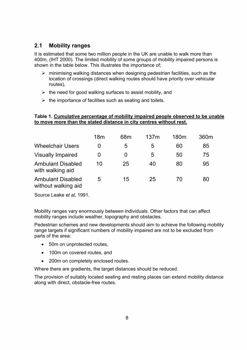
2.1 Mobility ranges It is estimated that some two million people in the UK are unable to walk more than 400m, (IHT 2000). The limited mobility of some groups of mobility impaired persons is shown in the table below. This illustrates the importance of; ¾ minimising walking distances when designing pedestrian facilities, such as the
location of crossings (direct walking routes should have priority over vehicular routes),
¾ the need for good walking surfaces to assist mobility, and ¾ the importance of facilities such as seating and toilets.
Table 1. Cumulative percentage of mobility impaired people observed to be unable to move more than the stated distance in city centres without rest.
18m 68m 137m 180m 360m Wheelchair Users 0 5 5 60 85 Visually Impaired 0 0 5 50 75 Ambulant Disabled 10 25 40 80 95 with walking aid Ambulant Disabled 5 15 25 70 80 without walking aid Source Leake et al, 1991.
Mobility ranges vary enormously between individuals. Other factors that can affect mobility ranges include weather, topography and obstacles. Pedestrian schemes and new developments should aim to achieve the following mobility range targets if significant numbers of mobility impaired are not to be excluded from parts of the area:
• 50m on unprotected routes,
• 100m on covered routes, and
• 200m on completely enclosed routes. Where there are gradients, the target distances should be reduced. The provision of suitably located seating and resting places can extend mobility distance along with direct, obstacle-free routes.
8
3. Footway and footpath facilities
Definition:Footway - the pedestrian part of the highway adjacent, or close, to the carriageway.Footpath - a pedestrian route not adjacent, or close, to the highway.
General guidelines: • Minimum footway of 2000mm width, free of obstructions.
• Footways to be provided on both sides of the carriageway.
• Footways and footpaths to be firm, even, level and slip-resistant even when wet.
• Joints should be closed and flush to prevent the trapping of canes or small wheels.
• For further guidance on footway requirements refer to the Cheshire County Council Design Aid document (section1). However, criteria described in this document supersede criteria in the County Council Design Guide.
3.1 Street furniture Street furniture can pose a physical obstruction to visually impaired pedestrians and people in wheelchairs. This includes any object which is placed on the footway (e.g.: seats, bollards, waste bins, barriers, utilities’ boxes, lampposts and traffic signs).
Guidelines: • Free standing items should:
• be a minimum of 1000mm high;
• Consistent width to ground level.
• Provide colour contrast to the surrounding environment or have; ¾ a minimum 150mm contrasting colour band at 1400 -1600mm above ground
level, or ¾ near the top if furniture is below 1400mm in height,
• All edges should be rounded.
• Free standing items should avoid obstructing the footway; ¾ Ideally they should be grouped together or in lines along one side of the
footway with as few additional poles as possible,
¾ Footway width should not be reduced to below 2000mm, minimum 1800mm. Absolute minimum 1200mm (with specific approval of Highway Authority),
¾ On existing footways an absolute minimum 1100mm clearance should be maintained.
• Lamps and signs should be wall mounted if possible.
• Overhead projections and signs should have a minimum clearance of 2100mm above the ground to the lowest point of the projection (see diagrams 3 and 4).
• Overhanging obstacles and tapering street furniture should have a tapping rail, the lower edge of which should be no more than 250mm above ground level.
• Where spaces occur under steps, ramps and stairways, these should be blocked off or provided with a protective rail.
• Cycle stands and the surrounding area should be defined for visually impaired pedestrians by a contrasting surface.
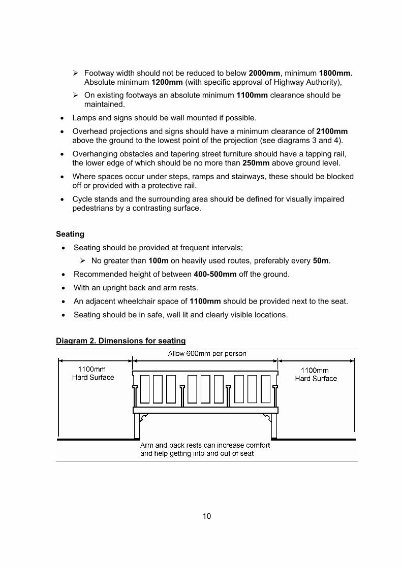
Seating • Seating should be provided at frequent intervals;
¾ No greater than 100m on heavily used routes, preferably every 50m.
• Recommended height of between 400-500mm off the ground.
• With an upright back and arm rests.
• An adjacent wheelchair space of 1100mm should be provided next to the seat.
• Seating should be in safe, well lit and clearly visible locations.
Diagram 2. Dimensions for seating
10
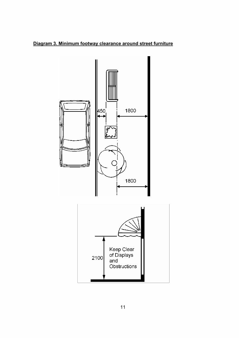
Diagram 3. Minimum footway clearance around street furniture
11
3.2 Signing and road markings Signs and information must be in a form that can be used by people with mobility impairments. It is particularly important to take into account the needs of visually impaired and hard of hearing pedestrians and to make information as simple and easy to understand as possible.
Guidelines: • Signage should include all the facilities within an area, particularly any services or
facilities for people with disabilities (e.g. rest rooms, accessible toilets, Shopmobility, accessible buses and recommended routes fully accessible by wheelchair users). ¾ Size of letters should be minimum height of 30mm. ¾ Typeface should be Sans Serif e.g. (Transport Medium or Helvetica). ¾ Words in sentence-case are easier to read than capital letters, because of the
shape they give to each word. ¾ Colour contrast is essential e.g. black text on a white or white text on a blue
background, though on some finger signposts white or gold lettering on a matt black background may be preferable.
• To reduce clutter and cost, and avoid obstruction to movement, the number of additional poles should be minimised by rationalising signs; ¾ by grouping them, ¾ fixing to other street furniture wherever possible, and ¾ wall mounting where feasible.
• Road signs must be mounted at least 2100mm from the ground. ¾ 2400mm for shared footway / cycleway
• Posts in the footway should be provided with a white visibility band 150mm deep at a height of between 1400-1600mm above ground.
• Where appropriate, tactile directional signing should be provided for visuallyimpaired pedestrians.
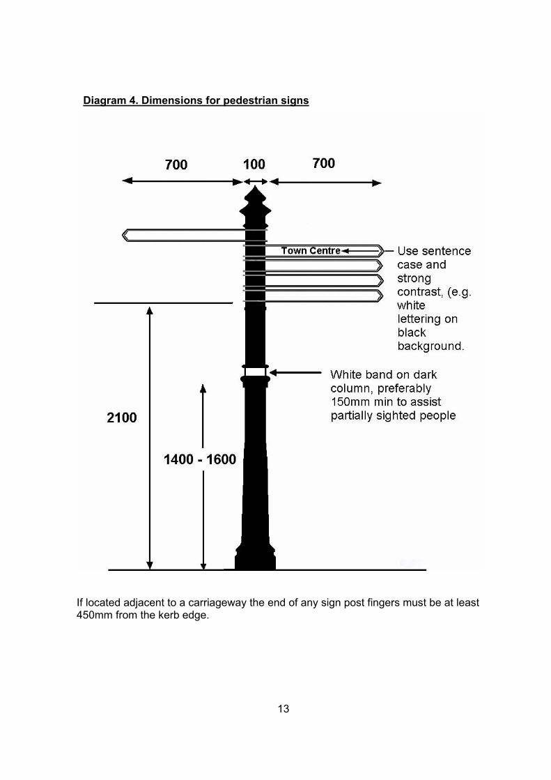
Diagram 4. Dimensions for pedestrian signs
If located adjacent to a carriageway the end of any sign post fingers must be at least 450mm from the kerb edge.
13
3.3 Lighting Good lighting is important from several points of view – personal security, safety, and ability to see signs and instructions. Many visually impaired pedestrians suffer with increased problems in poor lighting conditions. Recommendations for carriageway and footway lighting levels are given by BS 5489, the Code of Practice for Road Lighting. Part 3 of the Code recommends maintained average illuminance figures depending on the road category. Other factors include types of facilities and extent of night time pedestrian use. Guidelines:
• Good lighting should illuminate;
¾ any obstructions,
¾ changes in level, and
¾ changes in surface texture.
• Subways, footbridges, stairways and ramps should be lit to a higher level than the surrounding area.
• Lighting should be sited clear of trees and other obstructions, which would cast shadows and obstruct the light output.
14
3.4 Bus stops Getting about on foot or on wheels is an integral part of the total transport system. For many people, especially those without access to a car or who are unable to drive for medical reasons, travel by public transport is essential. The County Council’s Local Transport Plan sets out to upgrade all bus stops in Cheshire to new accessible standards by 2006. This includes providing new accessible bus shelters at all inbound bus stops wherever possible and practical, providing new bus stop poles, raised kerbs at boarding points, dropped crossing points, bus stop road markings and improved bus information Guidelines: • To aid visibility, transparent panels in bus shelters; ¾ should be divided by a mid-rail in a contrasting colour, and ¾ be lit to assist visibility in the dark.
• Priority should be given to providing shelters at stops used by a high proportion of elderly or disabled passengers (e.g. near sheltered accommodation or day-care centres).
• Any infrastructure and highway improvements should accommodate the needs of low, flat-floor, accessible buses and passengers with mobility problems. ¾ This includes the provision of tactile dropped crossing points for access to and
from the bus stop, and the bus stop opposite, where necessary.
• Further guidance on bus and bus interchange standards is available in the documents Cheshire Bus Strategy and Cheshire Interchange Strategy. These can be obtained from Cheshire County Council Transport Co-ordination Service (see page 62).
15
3.5 Trees and landscaping Trees and plants can improve the visual and environmental appearance of an area. However they can cause problems for people with mobility impairments if they are not sited and maintained correctly. Guidelines: • Specialist advice should be sought when choosing tree species to ensure that
trees do not have shallow, wide-spreading roots which will lift the footway surface.
• Where trees are planted next to, but not on, the highway, then the owner mustmaintain them to ensure that they do not become a hazard.¾ If the owner fails to do this, then the Highway Authority may serve notice that
the work be undertaken within a specified timescale; if not the Highway Authority may carry out the work and recharge the owner.
• Overhanging branches should be cut back to give at least 3000mm clear height to allow for regrowth.
• Landscaping on or next to the highway should be within clearly defined boundaries (e.g. raised kerb for identification by cane users and guide dogs).¾ A border of soft earth is not acceptable as it could trap wheels of pushchairs
and wheelchairs.
3.6 Access in the Countryside This code of practice mainly concerns the provision in the highway environment. Those who are involved in the design, planning and provision of access to the countryside should consult the British Telecom Countryside for All Standards and Guidelines (1997).
3.7 Access Controls Access controls frequently inhibit legal access for many disabled people especially those using any form of wheeled vehicle apart from a conventional pushed wheelchair and therefore are not recommended. Access controls are often used to try and curb the illegal use of motorcycles on footpaths or in recreational areas. This problem is rarely solved, those who can legally use a motor bike on the highway prefer to do so, and illegal riders may find their way into ‘protected’ areas regardless of access barriers.
16
3.8 Changes in level. Steps and ramps should be provided together where there is a change in level. Steps are inaccessible to wheelchair users and steps are preferable to ramps for people with some medical problems.
3.8.1 Ramps
A ramp is an external slope with a gradient of more than 5% (1 in 20), for guidance for ramps and steps serving subways and footbridges see section 4.4. Some wheelchair users lack the strength to propel themselves up a slope and have difficulty in slowing down or stopping when descending, so steep gradients can cause problems. Guidelines: • Ramps should be built with a minimum width of 1800mm and have a non-slip
surface.
• Maximum permitted gradient should be 8 %( 1 in 12). • Dual height handrails should be provided on each side (see 3.6.4).
• Ramp lengths will depend on the gradient; recommended limits are shown intable 2 below.
• Level resting places should be minimum 1500mm in length.
• Highlight top and bottom of the ramp by colour contrast.
• Good lighting should be provided.
• 1800mm clearance of street furniture and doors at top and bottom should be provided.
Table 2. Recommended maximum ramp lengths in relation to ramp gradient.
Length of Ramp Maximum gradient 2m 1:12
5m 1:15
10m 1:20
17

Diagram 5. Ramp detail.
3.8.2. Access ramps on public highways The principal entrance to a building should be accessible for disabled and non-disabled people alike. Many buildings are still inaccessible to some people. The construction of a ramp on the footway (public highway) can be considered only if it is structurally impossible to achieve a satisfactory solution within the curtilage of the building and/or by footway regrading. The need must be balanced against the following considerations;
• Maintaining access for statutory undertakers to underground pipes cables and equipment,
• Preserving adequate footway width, and
• Ensuring safe passage for pedestrians along the footway. An access ramp will not always be approved. There are many solutions available for improvements within the curtilage of a building. At some locations regrading or reshaping the footway may improve access. This requires prior permission of the Highway Authority (by a Highway Opening Order under the New Roads and Street Works Act 1991). Any alterations should avoid creating gradients that are problematic to pedestrians on the footway. If approval is given, it is recommended that a licence or legal agreement be drawn up, setting out responsibilities and liabilities for maintenance and repairs.
18
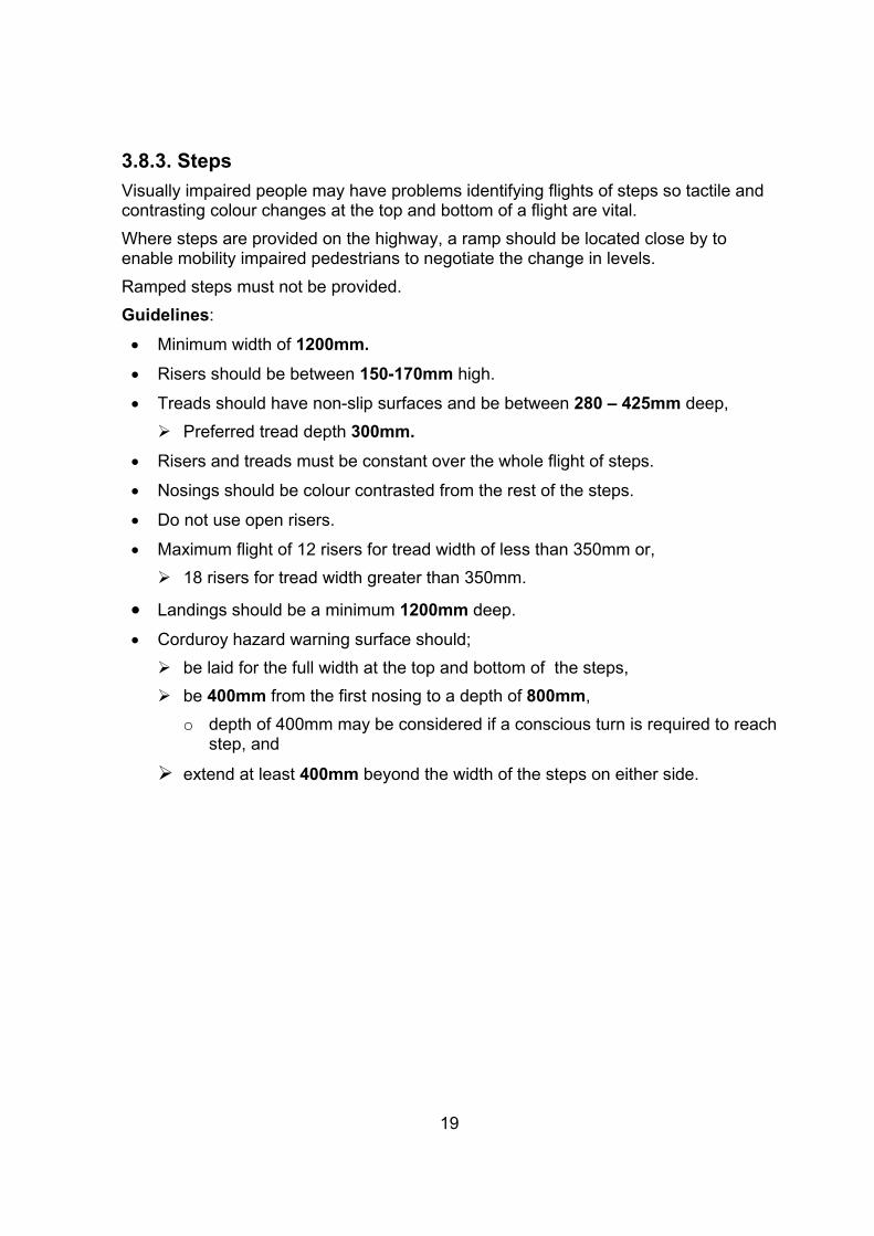
3.8.3. Steps Visually impaired people may have problems identifying flights of steps so tactile and contrasting colour changes at the top and bottom of a flight are vital. Where steps are provided on the highway, a ramp should be located close by to enable mobility impaired pedestrians to negotiate the change in levels. Ramped steps must not be provided. Guidelines:
• Minimum width of 1200mm. • Risers should be between 150-170mm high.
• Treads should have non-slip surfaces and be between 280 – 425mm deep, ¾ Preferred tread depth 300mm.
• Risers and treads must be constant over the whole flight of steps.
• Nosings should be colour contrasted from the rest of the steps.
• Do not use open risers.
• Maximum flight of 12 risers for tread width of less than 350mm or,¾ 18 risers for tread width greater than 350mm.
• Landings should be a minimum 1200mm deep.
• Corduroy hazard warning surface should;¾ be laid for the full width at the top and bottom of the steps, ¾ be 400mm from the first nosing to a depth of 800mm,
o depth of 400mm may be considered if a conscious turn is required to reach step, and
¾ extend at least 400mm beyond the width of the steps on either side.
19
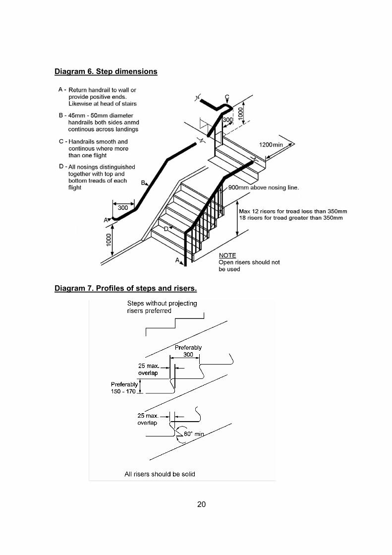
Diagram 6. Step dimensions
Diagram 7. Profiles of steps and risers.
20
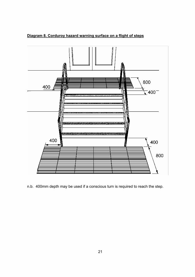
Diagram 8. Corduroy hazard warning surface on a flight of steps
n.b. 400mm depth may be used if a conscious turn is required to reach the step.
21
3.8.4 Handrails People with frail or arthritic fingers have difficulty in gripping objects, so the dimensions of the handrail are important. There should always be a handrail on both sides and for the full length of a flight of steps or a ramp. A second, lower, handrail should be considered where appropriate for children and people of short stature. Guidelines: • A contrasting colour or tone to surrounding environment should be used to make
it more conspicuous.
• 40mm-45mm in diameter and be situated 60 - 75mm from the wall.
• Height above the nose of a step and ramp 900-1000mm.
• Height above landings 1000-1100mm. • A second handrail between 550mm and 650mm above the step nosing or ramp
should be considered.
• The end of the handrail should extend horizontally beyond the top and bottomstep by at least 300mm.
• Positive end to the handrail or it should return to the wall – this indicates that the flight of steps or ramp has come to an end.
Diagram 9. Cross section of a mounted handrail
22
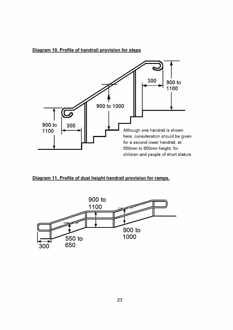
Diagram 10. Profile of handrail provision for steps
Diagram 11. Profile of dual height handrail provision for ramps.
23

3.9. Tactile paving
Tactile surfaces are used to give advanced warning of changes in level, priority or a road crossing to sight impaired people because they can be detected underfoot. Detailed guidance is provided on appropriate surfaces within DETR’s ‘Guidance on the Use of Tactile Paving Surfaces’, 1998. Tactile paving must only be used for the purposes described within the guidance Red coloured tactile paving must only be used with the blister tactile paving used at controlled crossings. Only the following three types of tactile paving are used regularly on the highway in Cheshire;
• Blister surface for pedestrian crossing points, (see section 4 for guidance),
• Corduroy hazard warning surface, (see section 3.6.3 for guidance), and
• Segregated shared cycle track/footway surface, (see section 5 for guidance).
3.9.1 Blister surface for pedestrian crossing points
Guidelines: • Should be used on all controlled and uncontrolled crossings;¾ where the footway has been dropped flush with the carriageway, or ¾ the carriageway has been raised level with the footway.
• Red coloured tactile paving should be used at all controlled crossings.
• Buff coloured tactile paving at all uncontrolled crossings.
• In conservation areas, consideration may be given to using brass studs, but not at controlled crossings.
• In locations where over-running by vehicles could be a problem then alternatives should be considered e.g. block paving or stick-on versions, which can also be more flexible in conforming to the footway profile.
24
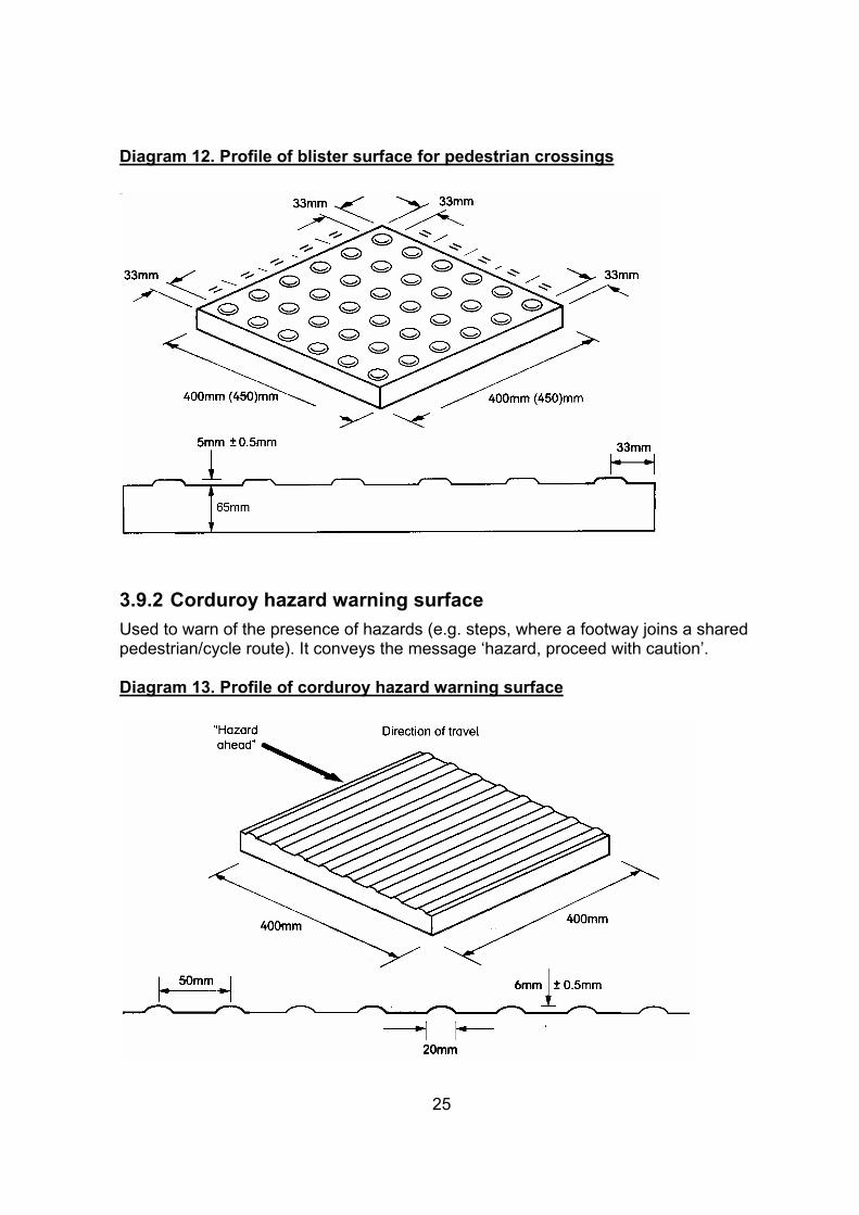
Diagram 12. Profile of blister surface for pedestrian crossings
3.9.2 Corduroy hazard warning surface Used to warn of the presence of hazards (e.g. steps, where a footway joins a shared pedestrian/cycle route). It conveys the message ‘hazard, proceed with caution’.
Diagram 13. Profile of corduroy hazard warning surface
25
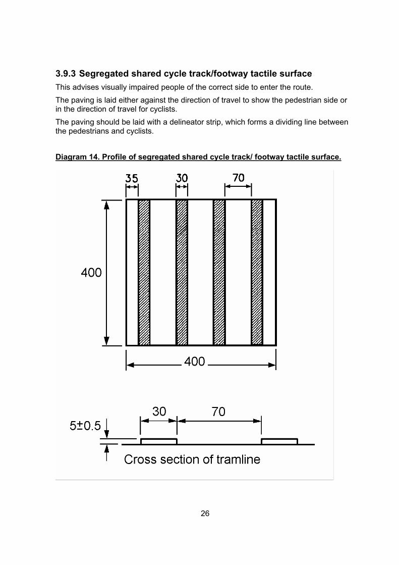
3.9.3 Segregated shared cycle track/footway tactile surface This advises visually impaired people of the correct side to enter the route. The paving is laid either against the direction of travel to show the pedestrian side or in the direction of travel for cyclists. The paving should be laid with a delineator strip, which forms a dividing line between the pedestrians and cyclists.
Diagram 14. Profile of segregated shared cycle track/ footway tactile surface.
26
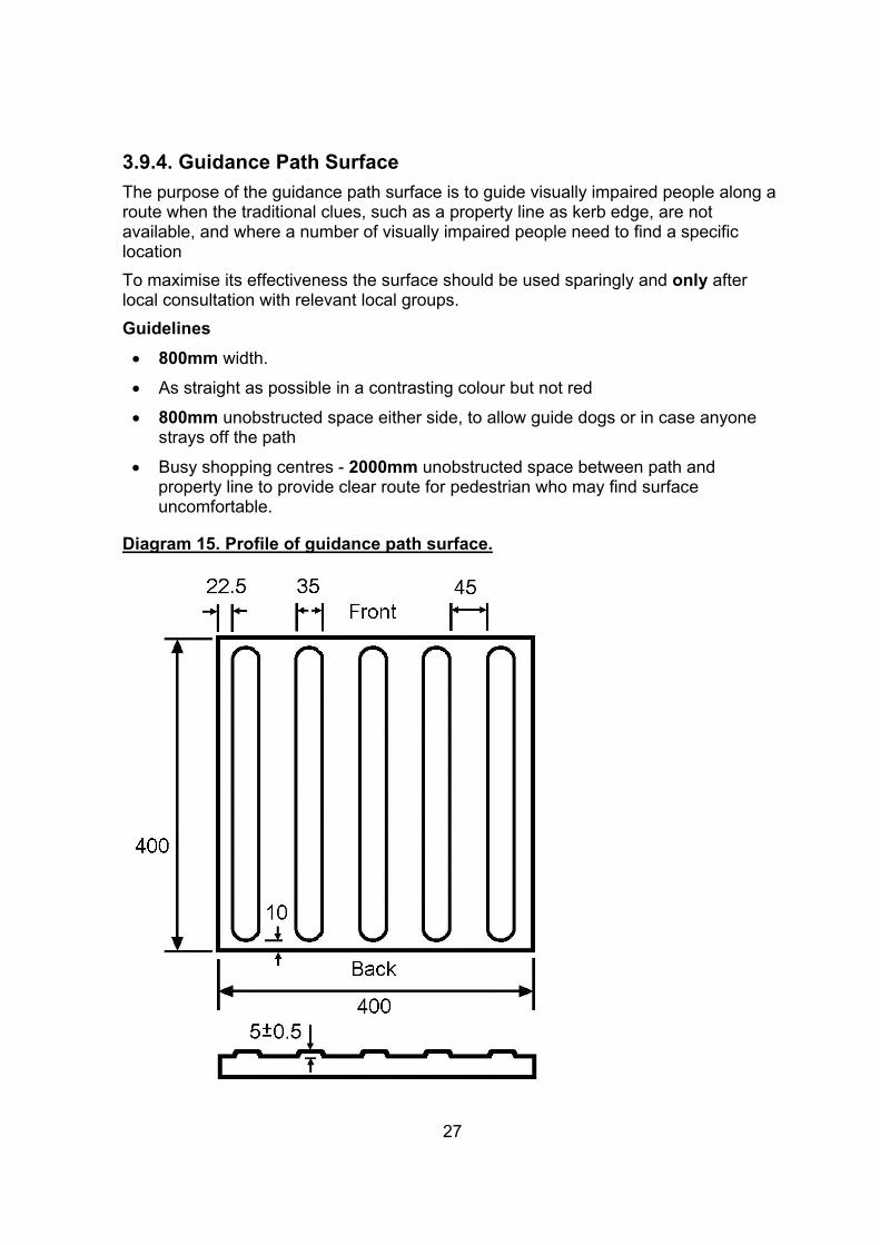
3.9.4. Guidance Path Surface The purpose of the guidance path surface is to guide visually impaired people along a route when the traditional clues, such as a property line as kerb edge, are not available, and where a number of visually impaired people need to find a specific location To maximise its effectiveness the surface should be used sparingly and only after local consultation with relevant local groups. Guidelines • 800mm width.
• As straight as possible in a contrasting colour but not red
• 800mm unobstructed space either side, to allow guide dogs or in case anyone strays off the path
• Busy shopping centres - 2000mm unobstructed space between path and property line to provide clear route for pedestrian who may find surfaceuncomfortable.
Diagram 15. Profile of guidance path surface.
27
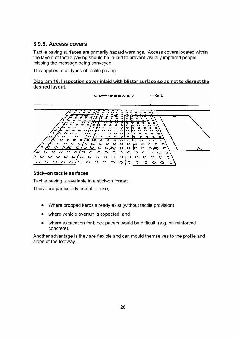
3.9.5. Access covers Tactile paving surfaces are primarily hazard warnings. Access covers located within the layout of tactile paving should be in-laid to prevent visually impaired people missing the message being conveyed. This applies to all types of tactile paving.
Diagram 16. Inspection cover inlaid with blister surface so as not to disrupt the desired layout.
Stick–on tactile surfaces Tactile paving is available in a stick-on format. These are particularly useful for use;
• Where dropped kerbs already exist (without tactile provision)
• where vehicle overrun is expected, and
• where excavation for block pavers would be difficult, (e.g. on reinforced concrete).
Another advantage is they are flexible and can mould themselves to the profile and slope of the footway.
28
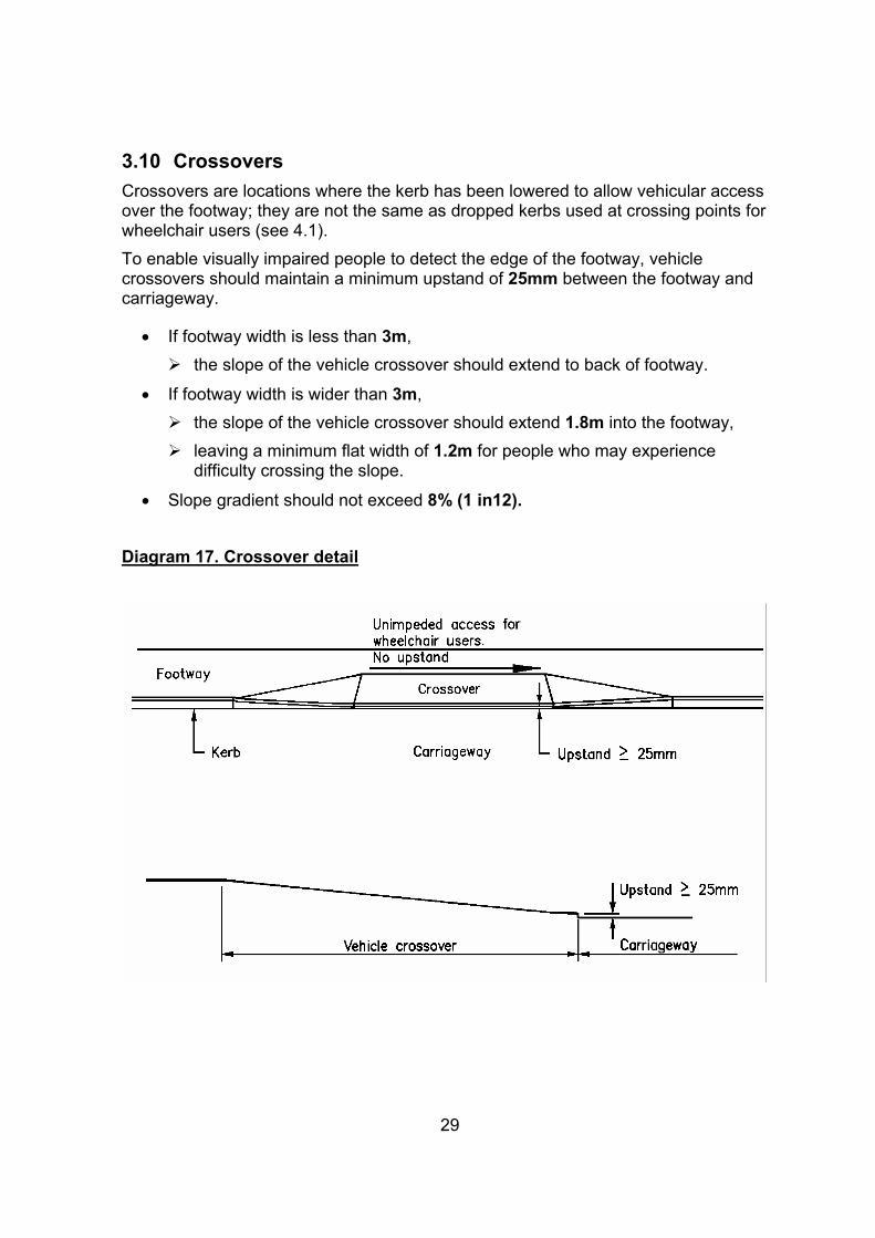
3.10 Crossovers Crossovers are locations where the kerb has been lowered to allow vehicular access over the footway; they are not the same as dropped kerbs used at crossing points for wheelchair users (see 4.1). To enable visually impaired people to detect the edge of the footway, vehicle crossovers should maintain a minimum upstand of 25mm between the footway and carriageway.
• If footway width is less than 3m, ¾ the slope of the vehicle crossover should extend to back of footway.
• If footway width is wider than 3m, ¾ the slope of the vehicle crossover should extend 1.8m into the footway, ¾ leaving a minimum flat width of 1.2m for people who may experience
difficulty crossing the slope.
• Slope gradient should not exceed 8% (1 in12).
Diagram 17. Crossover detail
29
3.11 Pedestrianised areas
Pedestrianised areas provide an opportunity to improve the safety, comfort and enjoyment of everyone using the area. Access to all parts of a pedestrianised area must be available, especially for people with mobility impairments who rely on motorised transport; this is a key element in its success. Means of reaching it other than walking and cycling include:
• Bus,
• Train,
• Park and Ride,
• Taxi,
• Community transport,
• Dial-a-ride, and
• Private cars.
Consideration must be given to the mobility ranges for mobility impaired people, mentioned in section 2, as to the locations of access points for all modes of transport. The nature of pedestrian schemes means that walking distances become longer and areas of schemes may become inaccessible for some if mobility ranges are exceeded.
• Where gradients exist the target distances should be reduced.
• The provision of seating and resting places can extend mobility distance.
30
4. Crossing facilities There are three types of crossing facilities:
1. Controlled – where pedestrians have direct control over vehicles e.g. Pelican, Puffin, Toucan, Pegasus and Zebra crossings.
2. Uncontrolled – where pedestrians usually do not have priority over vehicles and have to make a decision about whether it is safe to cross.
3. Grade separated - these are crossings separated from the level of the carriageway, most common in the form of footbridges and subways.
4.1 Dropped kerbs Kerbs present a significant barrier to the mobility of wheelchair or pushchair users. At locations where pedestrians are expected to cross, dropped kerbs should be provided. If a dropped kerb is provided on one side of the road, another MUST be provided on the other side, directly opposite and on any intervening central refuges.
Guidelines: • Where the kerb is dropped it should be flush with the carriageway surface;¾ If there are difficulties an upstand of 6mm maximum may be provided.
• Care should be taken when siting dropped kerbs to prevent them being placed close to drain covers or grilles that could trap the wheels of wheelchairs. ¾ Where this is not possible thought should be given to changing the grating,
also bearing in mind the needs of cyclists.
• Preferred slope gradient is 5% (1:20) and should not exceed 8% (1 in12). • If footway width is less than 2.5m, ¾ the ramp of the flush dropped kerb should extend to back of footway.
• if footway width is less than 1.5m, ¾ the footway should be reprofiled to obtain minimum1:12 gradient.
• Minimum width 0.914m (one-kerb length) may be provided where there is; ¾ a parking space reserved for the mobility impaired, or ¾ low pedestrian flow.
• Tactile paving should be installed as laid out in the DETR’s ‘Guidance on the Use of Tactile Paving Surfaces, 1998’, (see sections 4.2 and 4.3),
• Road Marking Diagram 1026.1 (Traffic Signs Regulations and General Directions -TSRGD) ‘H’ markings should be used at uncontrolled crossings to prevent blockage by parked vehicles where a problem is known to exist or is anticipated.
31
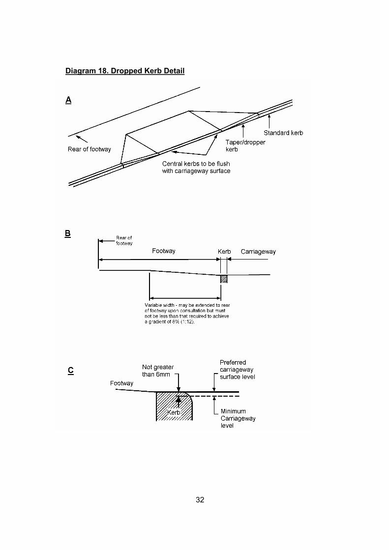
Diagram 18. Dropped Kerb Detail
32
4.2 Controlled crossings These crossings include signal controlled e.g. Pelican, Puffin, Toucan (shared with cyclists), Pegasus (shared with horses) and Zebra crossings. Guidelines:
• Flush dropped kerbs should be provided.
• Blister surfaces should be provided across the full width of the crossing. ¾ Blister surfaces must be RED. ¾ If the surrounding footway is in a similar colour, then a 150mm contrasting
border should be provided. ¾ The tactile paving layout will vary according to whether it is an inset or inline
crossing, (see diagrams 18 and 19). ¾ The stem should extend back to the rear of the footway from the tactile
paving adjacent to the push button control box to form an L shape.
• The Wait Box should be located on a post on the right hand side of the crossing as the pedestrian faces the road.
• This will allow a guide dog user to press the button whilst holding the dog in the left hand. ¾ The centre of the push button should be 1000-1100mm above the ground. ¾ Whilst standing on the tactile paving a visually impaired person should be
able to reach the wait box or find the post with a cane. ¾ For the benefit of visually impaired pedestrians, audible signals and/or
tactile cones that indicate when the green man is displayed and it is safe to cross, should be installed.
¾ Where crossings are close together, (e.g. on junctions), an audible signal from one may be mistakenly heard at another crossing. � If an audible signal cannot be used, then a tactile cone must be provided
beneath the push button control unit. This is beneficial to pedestrians who are both blind and deaf. � The user must be able to stand at the crossing point and make
contact with the cone. � If the red lights of the traffic signal heads fail, then the audible signal and
tactile cone should be switched off. ¾ On the posts, a white band 150mm wide placed at a height of 1400-
1600mm above ground level would assist visually impaired pedestrians.
• Good street lighting is essential to allow drivers to clearly see pedestrians who are waiting, especially at Zebra crossings.
33

Diagram 19. Layout of blister surface at inset and standard controlled crossings.
Diagram 20. Layout of blister surface at inline controlled crossings
34
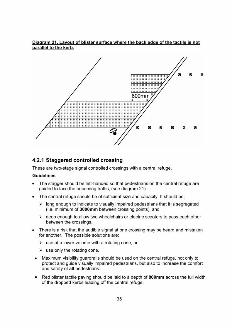
Diagram 21. Layout of blister surface where the back edge of the tactile is not parallel to the kerb.
4.2.1 Staggered controlled crossing These are two-stage signal controlled crossings with a central refuge. Guidelines • The stagger should be left-handed so that pedestrians on the central refuge are
guided to face the oncoming traffic, (see diagram 21).
• The central refuge should be of sufficient size and capacity. It should be; ¾ long enough to indicate to visually impaired pedestrians that it is segregated
(i.e. minimum of 3000mm between crossing points), and ¾ deep enough to allow two wheelchairs or electric scooters to pass each other
between the crossings.
• There is a risk that the audible signal at one crossing may be heard and mistaken for another. The possible solutions are: ¾ use at a lower volume with a rotating cone, or¾ use only the rotating cone.
• Maximum visibility guardrails should be used on the central refuge, not only to protect and guide visually impaired pedestrians, but also to increase the comfort and safety of all pedestrians.
• Red blister tactile paving should be laid to a depth of 800mm across the full width of the dropped kerbs leading off the central refuge.
35

Diagram 22. Layout of blister surface on a staggered pedestrian island
36
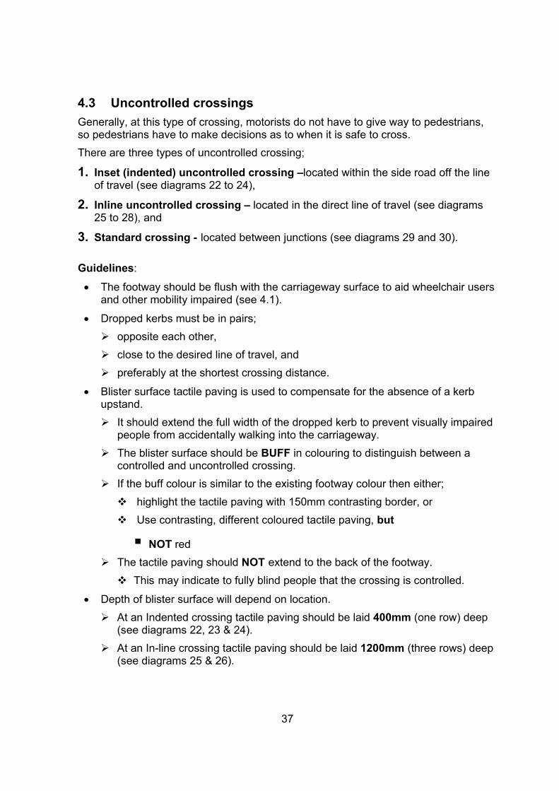
4.3 Uncontrolled crossings Generally, at this type of crossing, motorists do not have to give way to pedestrians, so pedestrians have to make decisions as to when it is safe to cross. There are three types of uncontrolled crossing;
1. Inset (indented) uncontrolled crossing –located within the side road off the line of travel (see diagrams 22 to 24),
2. Inline uncontrolled crossing – located in the direct line of travel (see diagrams 25 to 28), and
3. Standard crossing - located between junctions (see diagrams 29 and 30).
Guidelines:
• The footway should be flush with the carriageway surface to aid wheelchair users and other mobility impaired (see 4.1).
• Dropped kerbs must be in pairs; ¾ opposite each other, ¾ close to the desired line of travel, and ¾ preferably at the shortest crossing distance.
• Blister surface tactile paving is used to compensate for the absence of a kerb upstand. ¾ It should extend the full width of the dropped kerb to prevent visually impaired
people from accidentally walking into the carriageway. ¾ The blister surface should be BUFF in colouring to distinguish between a
controlled and uncontrolled crossing. ¾ If the buff colour is similar to the existing footway colour then either; � highlight the tactile paving with 150mm contrasting border, or � Use contrasting, different coloured tactile paving, but
� NOT red ¾ The tactile paving should NOT extend to the back of the footway. � This may indicate to fully blind people that the crossing is controlled.
• Depth of blister surface will depend on location. ¾ At an Indented crossing tactile paving should be laid 400mm (one row) deep
(see diagrams 22, 23 & 24). ¾ At an In-line crossing tactile paving should be laid 1200mm (three rows) deep
(see diagrams 25 & 26).
37

¾ At a Standard crossing tactile paving should be laid 800mm (two rows) deep (see diagrams 29 and 30).
¾ If located on the corner radius the minimum depths refer to the shortest side of the tactile paving layout (see diagrams 23 & 26)
• Ideally the crossing point should be indented 1m beyond the tangent of the corner radius. This provides the shortest route across the carriageway, however; ¾ Pedestrians waiting at a crossing point should be visible to approaching cars,
which can be difficult with encroaching buildings, garden walls and hedges. ¾ Visibility, road width, traffic flow and speed should be considered,¾ Large radii may take pedestrians away from desire line,
• Acute angled junctions may create large diversions on one side of the crossing or wide crossing points if crossing points are close to desire lines, (see diagram 24),
• to align themselves correctly in the direction of the crossing visually impaired pedestrians may use;
¾ the alignment of the blisters, or.
¾ the back edge of the tactile paving which must be at right angles to the direction of crossing
• Road markings to Diagram 1026.1 (Traffic Signs Regulations and GeneralDirections - TSRGD) may be used to prevent crossing points being blocked byparked cars.
Diagram 23. Layout of blister surface at indented uncontrolled crossing point
38
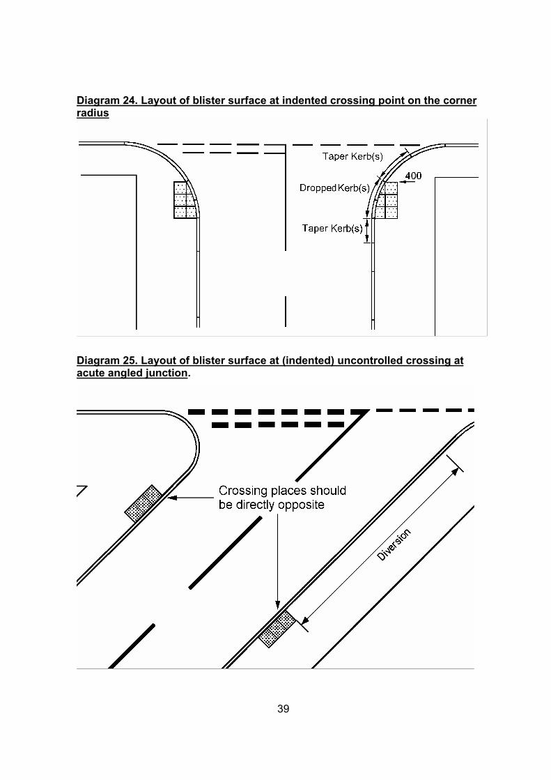
Diagram 24. Layout of blister surface at indented crossing point on the corner radius
Diagram 25. Layout of blister surface at (indented) uncontrolled crossing at acute angled junction.
39
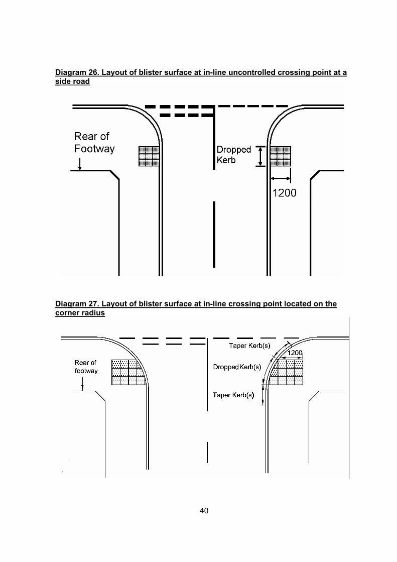
Diagram 26. Layout of blister surface at in-line uncontrolled crossing point at a side road
Diagram 27. Layout of blister surface at in-line crossing point located on the corner radius
40
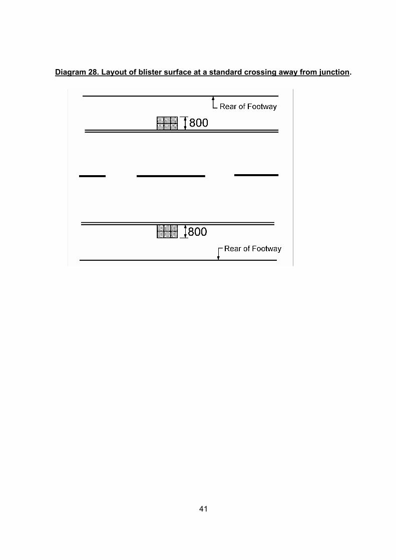
Diagram 28. Layout of blister surface at a standard crossing away from junction.
41
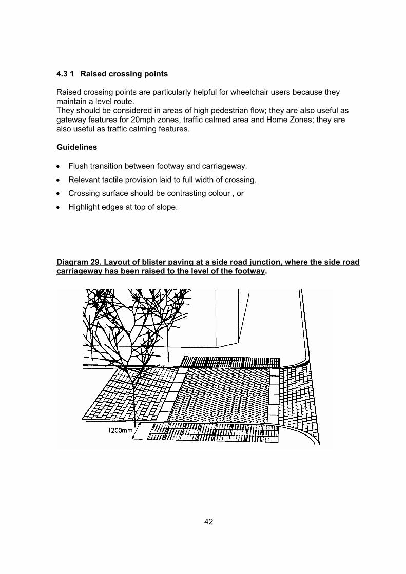
4.3 1 Raised crossing points
Raised crossing points are particularly helpful for wheelchair users because they maintain a level route. They should be considered in areas of high pedestrian flow; they are also useful as gateway features for 20mph zones, traffic calmed area and Home Zones; they are also useful as traffic calming features.
Guidelines
• Flush transition between footway and carriageway.
• Relevant tactile provision laid to full width of crossing.
• Crossing surface should be contrasting colour , or
• Highlight edges at top of slope.
Diagram 29. Layout of blister paving at a side road junction, where the side road carriageway has been raised to the level of the footway.
42
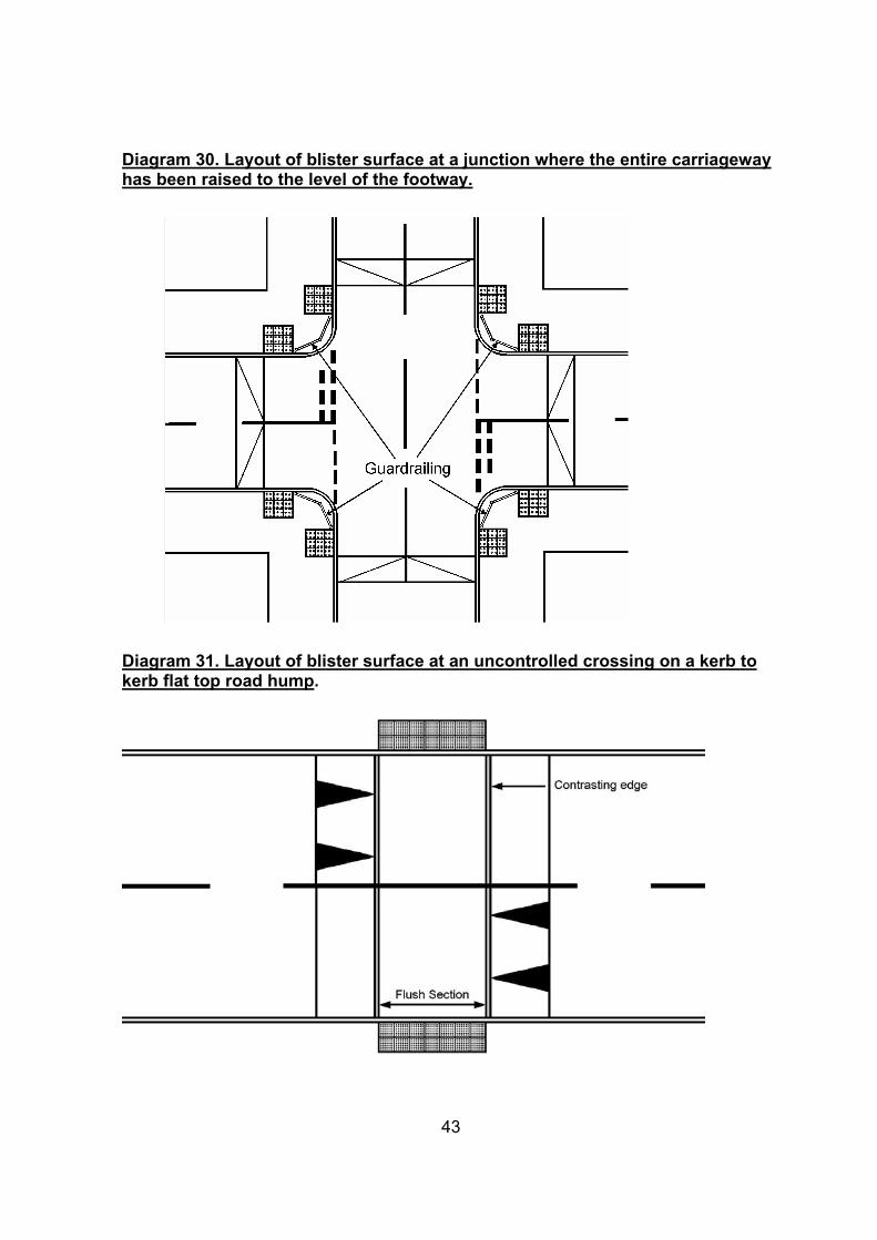
Diagram 30. Layout of blister surface at a junction where the entire carriageway has been raised to the level of the footway.
Diagram 31. Layout of blister surface at an uncontrolled crossing on a kerb to kerb flat top road hump.
43
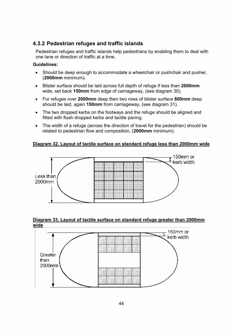
4.3.2 Pedestrian refuges and traffic islands Pedestrian refuges and traffic islands help pedestrians by enabling them to deal with one lane or direction of traffic at a time.
Guidelines: • Should be deep enough to accommodate a wheelchair or pushchair and pusher,
(2000mm minimum). • Blister surface should be laid across full depth of refuge if less than 2000mm
wide, set back 150mm from edge of carriageway, (see diagram 30).
• For refuges over 2000mm deep then two rows of blister surface 800mm deep should be laid, again 150mm from carriageway, (see diagram 31).
• The two dropped kerbs on the footways and the refuge should be aligned and fitted with flush dropped kerbs and tactile paving.
• The width of a refuge (across the direction of travel for the pedestrian) should be related to pedestrian flow and composition, (2000mm minimum).
Diagram 32. Layout of tactile surface on standard refuge less than 2000mm wide
Diagram 33. Layout of tactile surface on standard refuge greater than 2000mm wide
44

4.3.3 Triangular island pedestrian refuge
Guidelines: • A level area should be provided in the centre of the island to allow users to move
between crossings – especially important for wheelchair users.
• Pedestrians should be guided between crossing points by the use of kerbing edge surface or guardrails.
• Blister surface should be installed across the full width of each dropped kerb to a depth of 800mm, set back 150mm from the carriageway on all sides.
Diagram 34. Location of blister surface on a triangular pedestrian refuge
45

4.4 Footbridges and underpasses The quickest and easiest way to cross a road is on the surface. Footbridges and underpasses can be impossible barriers. They can confuse people with visual impairments, add additional distances for the frail and elderly, and provide unnecessary gradients for wheelchairs and pushchairs as well as adding to the real or perceived risk of being attacked. Guidelines: • Footbridges and underpasses should be carefully designed to minimise these
difficulties as much as possible, so maximising use.
• DETR Departmental Standards BD29/87 ‘Design Criteria for footbridges’ and TD 36/93 ‘Subways for Pedestrians and Pedal Cyclists’ set out design standards.
• Corduroy hazard warning surface should be installed at the top and bottom of flights of steps to aid visually impaired people.
¾ These areas should also be well lit.
46
5. Shared footway/cycle tracks Shared use facilities where pedestrians and cyclists are in close proximity to each other can cause problems especially for people with vision and hearing loss. The speed, quietness and proximity of some cyclists can cause anxiety and danger, particularly where there is no physical segregation between the two groups. Consideration will be given first to providing on-road cycling facilities. Where this is not possible then a shared footway/cycle track may be provided, where it is safe and reasonable to do so. There are two types of shared use footway/cycle track facilities, they are;
• Unsegregated, where pedestrians and cyclists mix freely, and
• Segregated, where the footway and cycle track are separated by a white line or physical barrier.
Where shared use facilities are introduced the National Cycle Network (NCN) guidelines should be followed:
Guidelines: • For an unsegregated facility the desirable minimum width is 3000mm. • For a segregated facility on an open site, a desirable width of 3000mm (1500mm
footpath, 1500mm cycle track), and
• on a bounded site 3250mm (1750mm footway, 1500mm cycle track) if thecarriageway is on the cycle track side.
• The facility should be set back 500mm from the carriageway.
• On a site bounded on both sides 3500mm (1750mm footway, 1750mm cycletrack)
• On segregated routes, road marking 1049, (TSRGD). a flat or embossed, white centre line should delineate the cyclist and pedestrian sides,
• To advise visually impaired people of the correct side to enter the track; ¾ The Segregated Shared Cycle track/footway tactile surface should be used ¾ The centre delineator strip can help the partially sighted keep to the
pedestrian side.
• In rural areas, shared surfaces should be created with cyclists and horse riders wherever it is safe and reasonable to do so if providing on-road facilities is impractical.
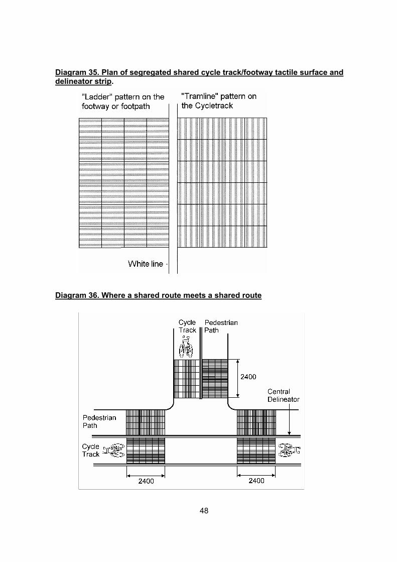
Diagram 35. Plan of segregated shared cycle track/footway tactile surface and delineator strip.
Diagram 36. Where a shared route meets a shared route
48
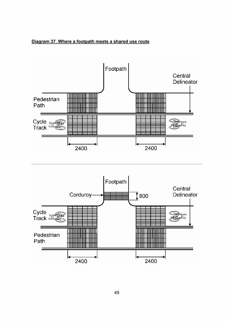
Diagram 37. Where a footpath meets a shared use route
49
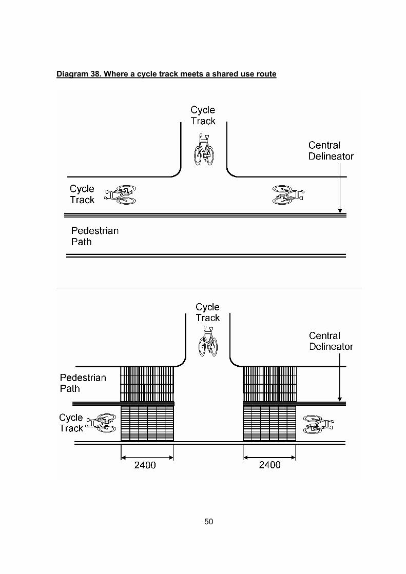
Diagram 38. Where a cycle track meets a shared use route
50
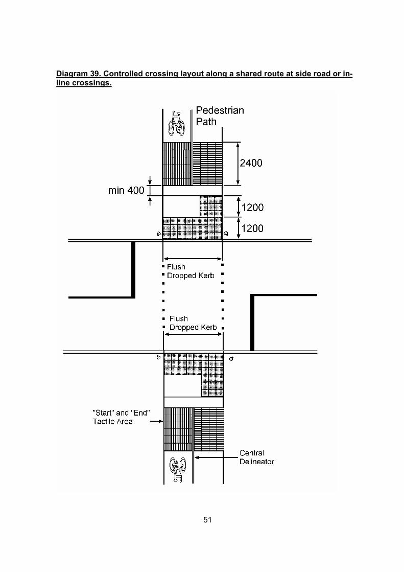
Diagram 39. Controlled crossing layout along a shared route at side road or in-line crossings.
51
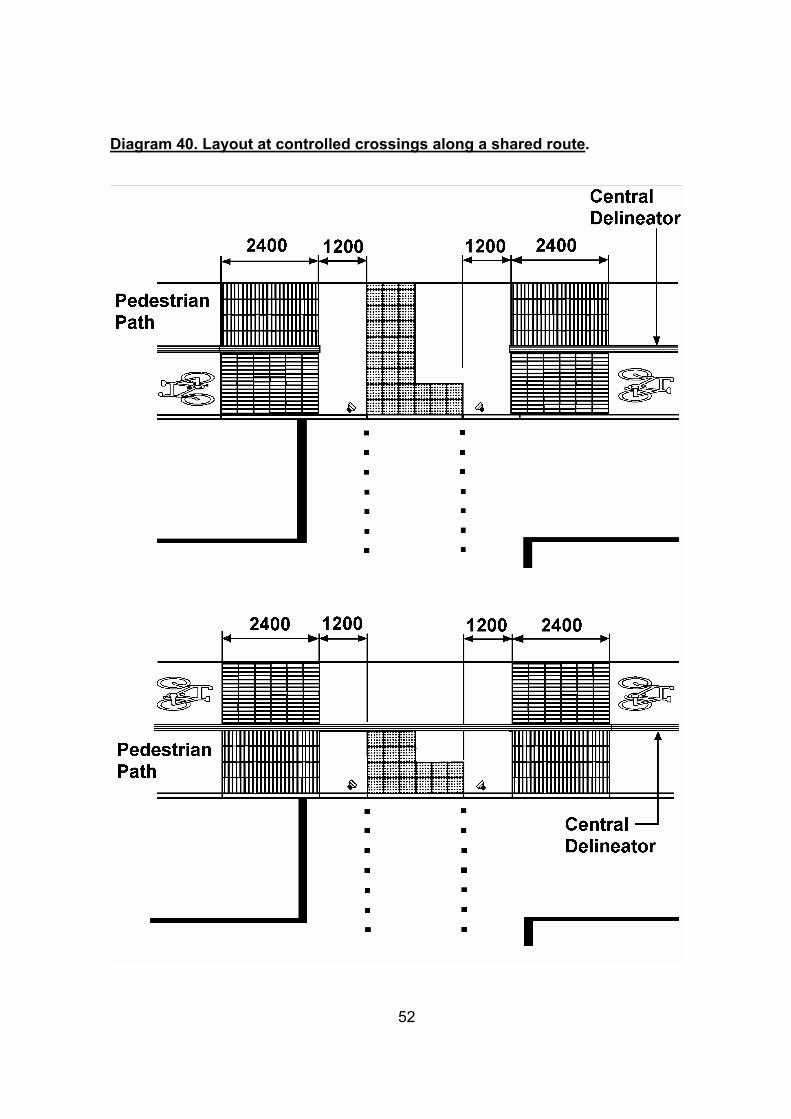
Diagram 40. Layout at controlled crossings along a shared route.
52
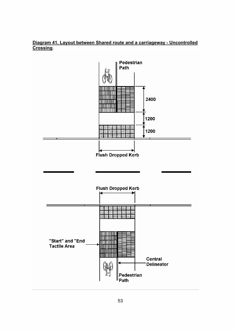
Diagram 41. Layout between Shared route and a carriageway - Uncontrolled Crossing.
53
6. Car parking For someone to obtain a Blue Badge they are expected not to be able to walk 50m or walk that far without pain. This should be used as a guide to the provision of disabled parking spaces and the location and spacing of seating. parking spaces for people with disabilities need to be larger than standard bays to allow extra space for access, especially if a vehicle occupant has to transfer to a wheelchair. some wheelchair are loaded using mechanical hoists which also require extra space to operate. Guidelines: • Dropped kerb access to parking bays should be provided.
• On-street parking parallel to the kerb; minimum 6600mm long by 2700mm wide.
• On-street parking at an angle to the kerb; minimum 4200mm long by 3600mm wide
• On - street parking bay markings should comply with diagrams 1028.3, 1032 or 1033 of the Traffic Signs Regulations and General Directions 2002.
• An 1800m wide bay may be provided where the overall width of an existing carriageway is insufficient to accommodate a wider bay.
• Off-street parking bays; a minimum 4800mm long by 2400mm wide plusadditional access space;¾ Where bays are parallel to the access aisle; an extra 1800mm length. ¾ For bays perpendicular to the access aisle; an extra 1200mm width.¾ Adjacent bays can share the same 1200mm access space. ¾ Where space permits a 1200mm safety zone may be added to the rear of
the bay.
• Disabled spaces should be placed on all sides of a pedestrianised area, ideally where the ground is flat.
• For further guidance on parking requirements refer to the Cheshire CountyCouncil Parking Standards document.
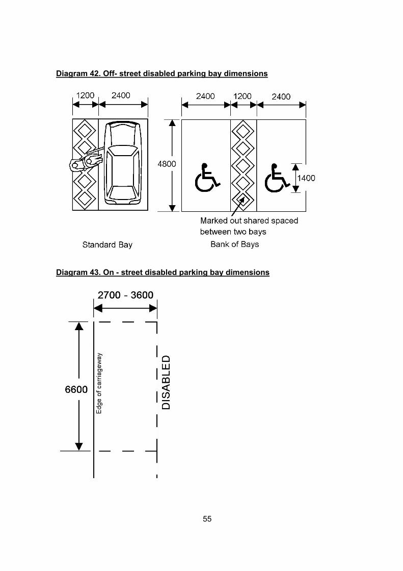
Diagram 42. Off- street disabled parking bay dimensions
Diagram 43. On - street disabled parking bay dimensions
55
7. Shopmobility Shopmobility schemes offer the use of powered scooters and wheelchairs on loan free of charge or for a small fee, to anyone with temporary or permanent mobility impairment. They then give people greater access to shopping and other facilities in town centres. Schemes within Cheshire are located in:
• Chester,
• Crewe,
• Ellesmere Port,
• Macclesfield,
• Northwich,
• Wilmslow, and
• Winsford.
Guidelines: • The mobility centre for the scheme should be based as near as possible to areas
where clients can arrive by public transport, with reserved parking for those arriving by car.
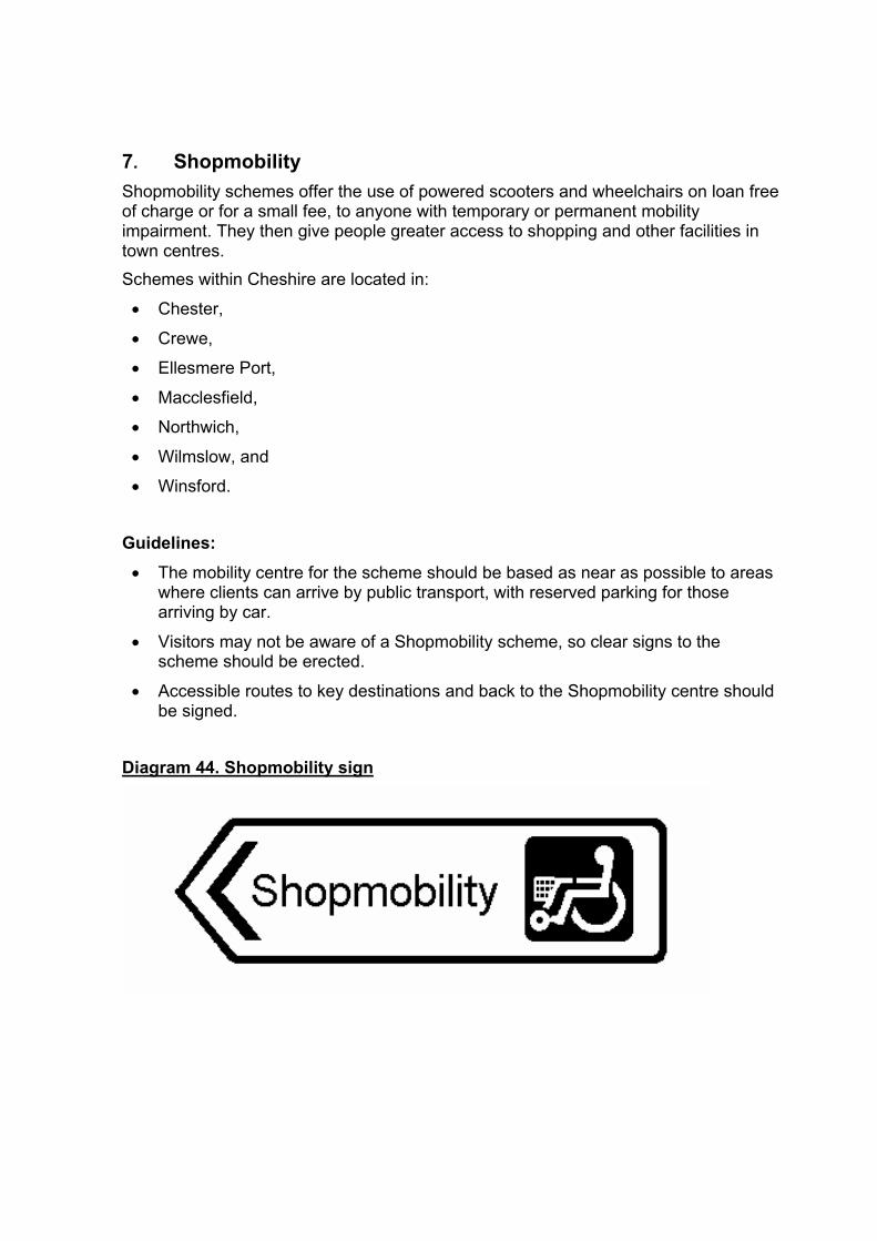
• Visitors may not be aware of a Shopmobility scheme, so clear signs to the scheme should be erected.
• Accessible routes to key destinations and back to the Shopmobility centre should be signed.
Diagram 44. Shopmobility sign
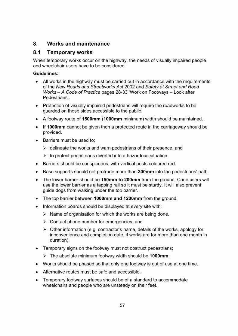
8. Works and maintenance 8.1 Temporary works When temporary works occur on the highway, the needs of visually impaired people and wheelchair users have to be considered. Guidelines: • All works in the highway must be carried out in accordance with the requirements
of the New Roads and Streetworks Act 2002 and Safety at Street and Road Works – A Code of Practice pages 28-33 ‘Work on Footways – Look after Pedestrians’.
• Protection of visually impaired pedestrians will require the roadworks to be guarded on those sides accessible to the public.
• A footway route of 1500mm (1000mm minimum) width should be maintained.
• If 1000mm cannot be given then a protected route in the carriageway should be provided.
• Barriers must be used to; ¾ delineate the works and warn pedestrians of their presence, and ¾ to protect pedestrians diverted into a hazardous situation.
• Barriers should be conspicuous, with vertical posts coloured red.
• Base supports should not protrude more than 300mm into the pedestrians’ path.
• The lower barrier should be 150mm to 200mm from the ground. Cane users will use the lower barrier as a tapping rail so it must be sturdy. It will also prevent guide dogs from walking under the top barrier.
• The top barrier between 1000mm and 1200mm from the ground.
• Information boards should be displayed at every site with; ¾ Name of organisation for which the works are being done,¾ Contact phone number for emergencies, and ¾ Other information (e.g. contractor’s name, details of the works, apology for
inconvenience and completion date, if works are for more than one month in duration).
• Temporary signs on the footway must not obstruct pedestrians; ¾ The absolute minimum footway width should be 1000mm.
• Works should be phased so that only one footway is out of use at one time.
• Alternative routes must be safe and accessible.
• Temporary footway surfaces should be of a standard to accommodatewheelchairs and people who are unsteady on their feet.
57

Diagram 45. Works on Footways
Diagram 46. Works on footway with temporary footway in carriageway
58
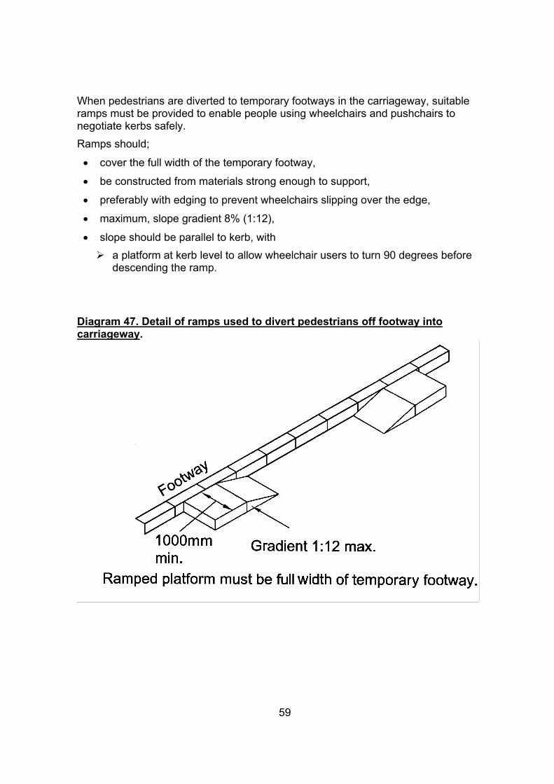
When pedestrians are diverted to temporary footways in the carriageway, suitable ramps must be provided to enable people using wheelchairs and pushchairs to negotiate kerbs safely. Ramps should;
• cover the full width of the temporary footway,
• be constructed from materials strong enough to support,
• preferably with edging to prevent wheelchairs slipping over the edge,
• maximum, slope gradient 8% (1:12),
• slope should be parallel to kerb, with ¾ a platform at kerb level to allow wheelchair users to turn 90 degrees before
descending the ramp.
Diagram 47. Detail of ramps used to divert pedestrians off footway into carriageway.
59
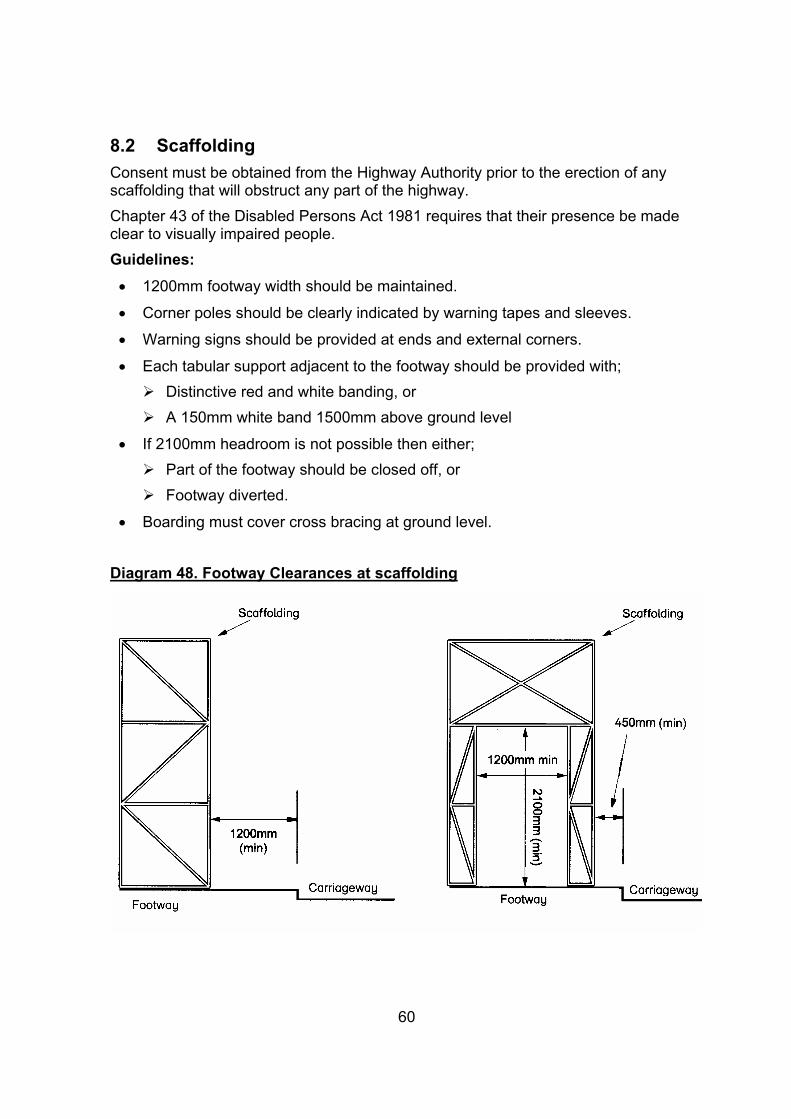
8.2 Scaffolding Consent must be obtained from the Highway Authority prior to the erection of any scaffolding that will obstruct any part of the highway. Chapter 43 of the Disabled Persons Act 1981 requires that their presence be made clear to visually impaired people. Guidelines: • 1200mm footway width should be maintained.
• Corner poles should be clearly indicated by warning tapes and sleeves.
• Warning signs should be provided at ends and external corners.
• Each tabular support adjacent to the footway should be provided with;¾ Distinctive red and white banding, or¾ A 150mm white band 1500mm above ground level
• If 2100mm headroom is not possible then either;¾ Part of the footway should be closed off, or ¾ Footway diverted.
• Boarding must cover cross bracing at ground level.
Diagram 48. Footway Clearances at scaffolding
60
8.3 Site reinstatement and maintenance
Poor maintenance is a danger and a barrier for mobility impaired pedestrians. Uneven and cracked paving flags, poor reinstatements, ruts and gaps can lead to trips, trapped wheels and canes, and cause uncomfortable jolts to wheelchair and pram users. Cheshire County Council currently carries out scheduled safety inspections and subsequent maintenance of footways, the frequency of which is dictated by the importance of the route. Frequencies range between once every two weeks to once every six months and are increased under conditions where motorised traffic has to be diverted onto the footway. Further information on the frequencies and inspection methods can be obtained from Cheshire County Council’s handbook ‘Code of Practice for Highway Safety Inspections’.
Guidelines: • On completion of any works, all materials must be cleared from the highway,
which should be left in a clean and tidy condition.
• Any damage caused to the footway or carriageway must be made good to the satisfaction of the County Council.
• Routine inspections and maintenance programmes should ensure that all routes are accessible to people with mobility impairments.
• It is important to monitor the condition of tactile paving and plan for replacement; if the blisters fall below 3mm the material is likely to be virtually undetectable.
• The New Roads and Streetworks Act 2002 requires the replacement of tactile paving when it is removed or disturbed in the course of works being carried out on the footway.
61

9. Other Information 9.1 Useful addresses 9.1.1 Cheshire County Council Highways Service For advice on planning applications, technical advice on installing street furniture or to report faults and obstructions to the highway and street furniture please contact the local joint highway team;
Chester District Highways Maintenance office Guilden Sutton Depot Guilden Sutton Chester, Cheshire CH3 7EX Tel: 0845 020 0666 email: [email protected].
Congleton District Congleton Joint Highways Team Westfields Middlewich Road Sandbach, Cheshire CW11 3HZ Tel: 0845 020 0666 email: [email protected]
Crewe & Nantwich District Crewe & Nantwich Highways Team Brierley Business Centre Mirion Street Crewe, Cheshire CW1 2AZ Tel: 0845 020 0666 email: [email protected]
Ellesmere Port & Neston District Ellesmere Port & Neston Joint Highways Team Council Offices 4 Civic Way Ellesmere Port, Cheshire CH65 0BE Tel: 0845 020 0666 email: [email protected]
Macclesfield District Macclesfield Joint Highways Team London Road Lyme Green Macclesfield, Cheshire SK11 0JX Tel: 0845 020 0666 email: [email protected]

Vale Royal District Vale Royal Joint Highways Team Phoenix House Clough Road Winsford, Cheshire CW7 4BD Tel: 0845 002 0666 email: [email protected]
For lighting policy and advice, contact: Phil Edwards Cheshire County Council Engineering Service Backford Hall Chester, Cheshire CH1 6EA Tel: 01244 973737 email: [email protected]
For signing advice, contact: Neil Theobald Cheshire County Council Backford Hall Chester, Cheshire CH1 6EA Tel: 01244 973621 email: [email protected]
To discuss pedestrian provision and details of this code of practice contact: David Reeves Cheshire County Council Backford Hall Chester, Cheshire CH1 6EA Tel: 01244 973762 email; [email protected]
If you are unsure who to contact, ring a County Council information point: Tel 0845 11 333 11 email; [email protected]
Complaints If you are not satisfied with the service you receive from the County Council’s Engineering Service, please contact; County Engineer Cheshire County Council Backford Hall Chester, Cheshire CH1 6EA Tel: 01244 973575 email:
63

9.1.2 Other Cheshire County Council Services Transport Co-ordination For information on Cheshire County Council’s Bus Strategy or Bus Interchange Strategy contact: Colin Kennington Transport Co-ordination Service Cheshire County Council Rivacre Business Centre Mill Lane Ellesmere Port, Cheshire CH66 3TL Tel. 01244 603896 email: [email protected]
Social Service Access Team These are the first point of contact for help or information for all aspects relating to disability, visual impairment, and deafness. Email: www.cheshire.gov.uk/social
Central Area County Offices Watling Street Northwich, Cheshire CW9 5ET Tel: 01606 814900 County Offices Wyvern House The Drumber Winsford, Cheshire CW7 1AU Tel: 01606 815600 Delamere House Delamere Street Crewe, Cheshire CW1 2LL Tel: 01270 505100
East Area County Offices Chapel Lane Wilmslow, Cheshire SK9 1PU Tel: 01625 534700 Macclesfield Library Jordangate Macclesfield, Cheshire SK10 1EG Tel: 01625 534700 Congleton Library Market Square Congleton, Cheshire CW12 1BU Tel: 01625 534700
64
West Area Goldsmith House Hamilton Place Chester, Cheshire CH1 1SE Tel: 01244 603400
Coronation Road Ellesmere Port, Cheshire CH65 9AA Tel: 0151 357 4500
Dial-a-Ride and Community Transport
Cynthia Nelson Rivacre Business Centre Mill Lane, Ellesmere Port CH66 3TL Tel: 01244 603269 email: [email protected]
65

9.1.3 Local Organisations: These groups can offer advice on mobility issues and will have knowledge of local conditions and will be able to advise on specific local issues.
Cheshire Disabilities Federation Central Office Hartford Business Centre Chester Road Northwich, Cheshire CW9 2AP Tel: 01606 888255 email: [email protected]
Cheshire Deafness Support Network 144 London Road Northwich Cheshire CW9 5HA Tel: 01606 47831 email: [email protected]
Congleton Disabled Access Club 8 The Green, Astbury Street Congleton Cheshire CW12 4EL
Tel: 01260 271997 email: [email protected]
Congleton Disabled Club 197 Longdown Road Congleton Cheshire CW12 4QT
Tel: 01260 273494
D.I.A.L. Chester Disability Information Centre Dial House Hamilton Place Chester Cheshire CH1 2BH Tel: 01244 345655 email: [email protected] Website: www.dialhousechester.org.uk
Disability Resource Exchange PO Box 82 Crewe, Cheshire CW2 8FA Tel: 01270 501535 email: [email protected]
66

Disabled Information Centre Ellesmere Port (DICE) 6 Mercer Walk Port Arcades Ellesmere Port Cheshire CH65 0AP Tel: 0151 356 8253 email: [email protected]
IRIS Vision Resource Centre 14 Chapel Street Crewe Cheshire CW2 7DQ Tel: 01270 250316 email: [email protected] Website: www.iriscentre.comcarenet.net
Living Streets (Wilmslow). Dale Langham 32 Curzon Mews Wilmslow Cheshire SK9 5JN Tel: 01625 548572 email: [email protected]
Macclesfield Access Group 29 Westbury Drive Macclesfield Cheshire SK11 8LR
Tel: 01625 427453
Macclesfield Blind Society 15 Queen Victoria Street Macclesfield Cheshire SK11 6LP
Tel: 01625 422602
Vision Support 67 Liverpool Road Chester Cheshire CH2 1AP Tel: 01244 651905 email: [email protected]
Wilmslow Access Action Group Alan Pearce 9 Curzon Mews Wilmslow Cheshire SK9 5JN Tel: 01625 536602 email; [email protected]
67
9.1.4 National organisations:
Arthritis Care 18 Stephenson Way London NW1 2HD Tel: 020 7380 6500 email: [email protected]
British Standards Institute 389 Chiswick High Road London W4 4AL Tel: 0208996 7400 email: [email protected]
Centre for Accessible Environments Nutmeg House 60 Gainsford Street London SE1 2NY Tel: 020 7357 8182 website: www.cae.org.uk
Community Transport Association Highbank Halton Street Hyde, Cheshire SK14 2NY Tel: 0161 366 6685 email: [email protected]
Deafblind UK 100 Bridge Street Peterborough, Cambridgeshire PE1 1DY Tel: 01733 358356 email: [email protected]
The Mobility and Inclusion Unit The Department for Transport Zone 1/18 Great Minister House 76 Marsham Street London SW1P 4DR Tel: 020 7944 6102 email: [email protected]
Disabled Drivers Association National HQ Ashwellthorpe Norwich NR16 1EX Tel: 01508 489449 email: [email protected]
The Disabled Persons Transport Advisory Committee (DPTAC)
68
Zone 1/14 Great Minister House 76 Marsham Street London SW1P 4DR Tel: 020 7944 6100 email: [email protected]
Institute of Historic Building Conservation 3 Stafford Road Tunbridge Wells, Kent TN2 4QZ email: [email protected]
Institution of Highways and Transportation 6 Endsleigh Road London W13 0RE Tel: 020 7387 2525 email: [email protected]
Joint Mobility Unit (JMU) 224 Great Portland Street London W1N 6AA Tel: 020 7387 2233 website: www.jmuaccess.org.uk Jointly funded by the RNIB and Guide Dogs for the Blind and gives advice on the design of facilities to meet the needs of visually impaired people.
Living Streets 31-33 Bondway London SW8 1SJ Tel: 020 7820 1010 email: [email protected] Website: www.livingstreets.org.uk National Federation of Shopmobility UK 12 City Forum 250 City Road London EC1V 8AF Tel: 020 7689 1040 website: www.justmobility.co.uk
Royal Association for Disability and Rehabilitation (RADAR) Address as for Shopmobility Tel: 020 7250 3222 website: www.radar.org.uk
Royal National Institute for the Blind (RNIB) 105 Judd Street London WC1H 9NE Tel: 020 7388 1266 website: www.rnib.org.uk
69

Royal National Institute for the Deaf (RNID) 19-23 Featherstone Street London EC19 8SL Tel: 020 7296 8000 website: www.rnid.org.uk
Royal Society for Mentally Handicapped Children and Adults (MENCAP) 123 Golden Lane London EC1Y 0RT Tel: 020 7454 0454
Scope 6 Market Road London N7 9PW Tel: 020 7619 7399
70
9.2 Bibliography
9.2.1 Technical Guidance
British Standards 1992; BS5489:1992 Road Lighting. British Standards 2001; BS8300:2001 Design of buildings and their approaches to meet the needs of disabled people – Code of practice. British Telecom 1997; BT Countryside for All – Standards and Guidelines – A Good Practice Guide to Disabled People’s Access in the Countryside. BT Cheshire County Council 1996; Design Aid: Housing, Industrial and Commercial Estate Roads. CCC Cheshire County Council 2000; Code of Practice for Highway Safety Inspections. Inspectors’ Handbook, Second Edition. CCC. Department for Transport 2002; Code of Practice ‘Safety at Street Works and Road Works. HMSO DfT 1987; Departmental Standard BD 29/87, Design Criteria for Footbridges. HMSO. DfT 1991; Traffic Advisory Leaflet 4/91 ‘Audible and Tactile Signals at Pelican Crossings’ HMSO DfT 1991; Traffic Advisory Leaflet 5/91 ‘Audible and Tactile Signals at Signal Controlled Junctions’ HMSO. DfT 1993; Design Manual for Roads and Bridges TD36/93, Subways for Pedestrians and Cyclists Layout and Dimensions. HMSO DfT 1993; Traffic Advisory Leaflet 4/93 ‘Pavement Parking’ HMSO DfT 1995; Local Transport Note 1/95 ‘The Assessment of Pedestrian Crossings’ HMSO DfT 1995; Local Transport Note 2/95 ‘The Design of Pedestrian Crossings’ HMSO DfT 1995; Traffic Advisory Leaflet 5/95 ‘Parking for Disabled People’ HMSO DfT 1998; Traffic Advisory Leaflet 4/98 ‘Toucan Crossing Development’ HMSO DfT 1998; ’Guidance on the Use of Tactile Paving’ HMSO (supersedes Disability Unit Circular 1/91) DfT 2001; Traffic Advisory Leaflet 1/01 ‘Puffin Pedestrian Crossing’ HMSO DfT 2002; Traffic Advisory Leaflet 1/02 ‘The Installation of Puffin Pedestrian Crossings’ HMSO. DfT 2001; New Road and Street Works Act 1991; HMSO and subsequent amendments DfT 200T Statutory Instrument 2002/3113. Traffic Signs Regulations and General Directions 2002 (TSRGD)
9.2.2 Further Reading DfT 1998; ‘Places, Streets and Movement: A Companion Guide to Design Bulletin 32, Residential Roads and Footpaths’ HMSO DfT 2002; Inclusive Mobility: A Guide to Best Practice on Access to Pedestrian and Transport Infrastructure DfT 2003 Traffic Advisory Leaflet 5/03 ‘Walking Bibliography’ HMSO Duncan-Jones, Beata 1998; ‘Understanding Tactile Paving’ London Borough of Hammersmith and Fulham Institution of Highways and Transportation 1991; Revised Guidelines ‘Reducing mobility Handicaps – Towards a Barrier Free Environment’ Institution of Highways and Transportation 2000; ‘Guidelines for Providing for Journeys on Foot’ Kent County Council 1999; ‘Highways suitable for the Mobility Impaired - A Code of Practice’ Merseytravel 1999; ‘Merseyside Code of Practice on Access and Mobility’ Liverpool Oxley, Philip 2000; ‘Guidance on Best Practice in Meeting the Needs of Disabled People in the Pedestrian Environment and in Transport Related Infrastructure (Second Draft)’ Cranfield Centre for Logistics and Transportation.
72