Embed Size (px)
Citation preview
Subsection XX (pDRIVE PULLEY WITH CLICKER)
mmr2017-040 1
pDRIVE PULLEY WITH CLICKER
SERVICE TOOLS
Description Part Number Page
CIRCLIP INSTALLER/REMOVER................................................... 420-664......................................... 4–5
CLUTCH HOLDER......................................................................... 420-660 .......................................3, 12
DRIVE PULLEY OPENING TOOL .................................................. 420-665 .........................................4, 8
DRIVE PULLEY SUPPORT ............................................................ 529 036 371 ..................................... 4–5, 7
GREASE INJECTOR ...................................................................... 529 036 376 ........................................... 10
PDRIVE PULLER ........................................................................... 420-661......................................... 3–4
PULLEY SPRING COMPRESSOR TOOL....................................... 420-663 ................................. 4–5, 7–8
REMOVING AXLE TOOL............................................................... 420-662 ..................................... 4, 6–8
SERVICE PRODUCTS
Description Part Number Page
ISOFLEX GREASE TOPAS NB 52 ................................................. 293 550 021 ........................................... 10 PULLEY
FLANGE CLEANER ......................................................... 413 711 809 ............................................. 9
Subsection XX (pDRIVE PULLEY WITH CLICKER)
2 mmr2017-040
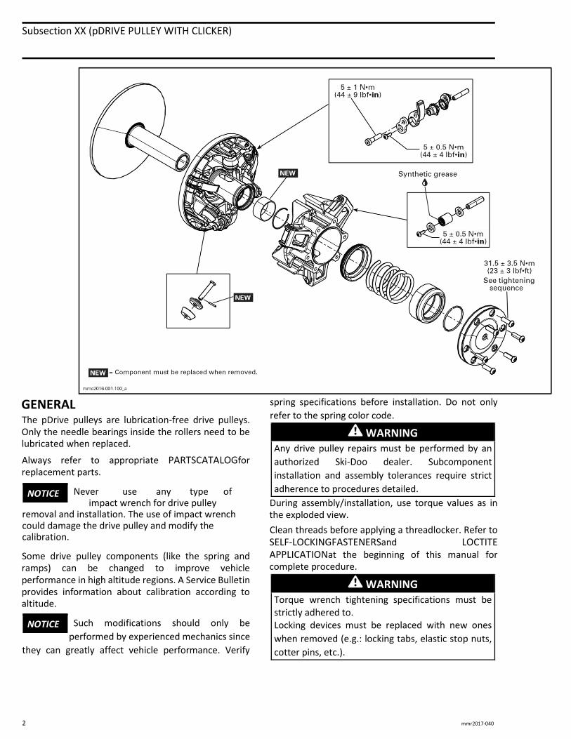
GENERAL The pDrive pulleys are lubrication-free drive pulleys. Only the needle bearings inside the rollers need to be lubricated when replaced.
Always refer to appropriate PARTSCATALOGfor replacement parts.
Never use any type of impact wrench for drive pulley
removal and installation. The use of impact wrench could damage the drive pulley and modify the calibration.
Some drive pulley components (like the spring and ramps) can be changed to improve vehicle performance in high altitude regions. A Service Bulletin provides information about calibration according to altitude.
Such modifications should only be
performed by experienced mechanics since
they can greatly affect vehicle performance. Verify
spring specifications before installation. Do not only
refer to the spring color code.
WARNING
Any drive pulley repairs must be performed by an
authorized Ski-Doo dealer. Subcomponent
installation and assembly tolerances require strict
adherence to procedures detailed.
During assembly/installation, use torque values as in the exploded view.
Clean threads before applying a threadlocker. Refer to SELF-LOCKINGFASTENERSand LOCTITE APPLICATIONat the beginning of this manual for complete procedure.
WARNING
Torque wrench tightening specifications must be strictly adhered to. Locking devices must be replaced with new ones
when removed (e.g.: locking tabs, elastic stop nuts,
cotter pins, etc.).
NOTICE
NOTICE
Subsection XX (pDRIVE PULLEY WITH CLICKER)
mmr2017-040 3
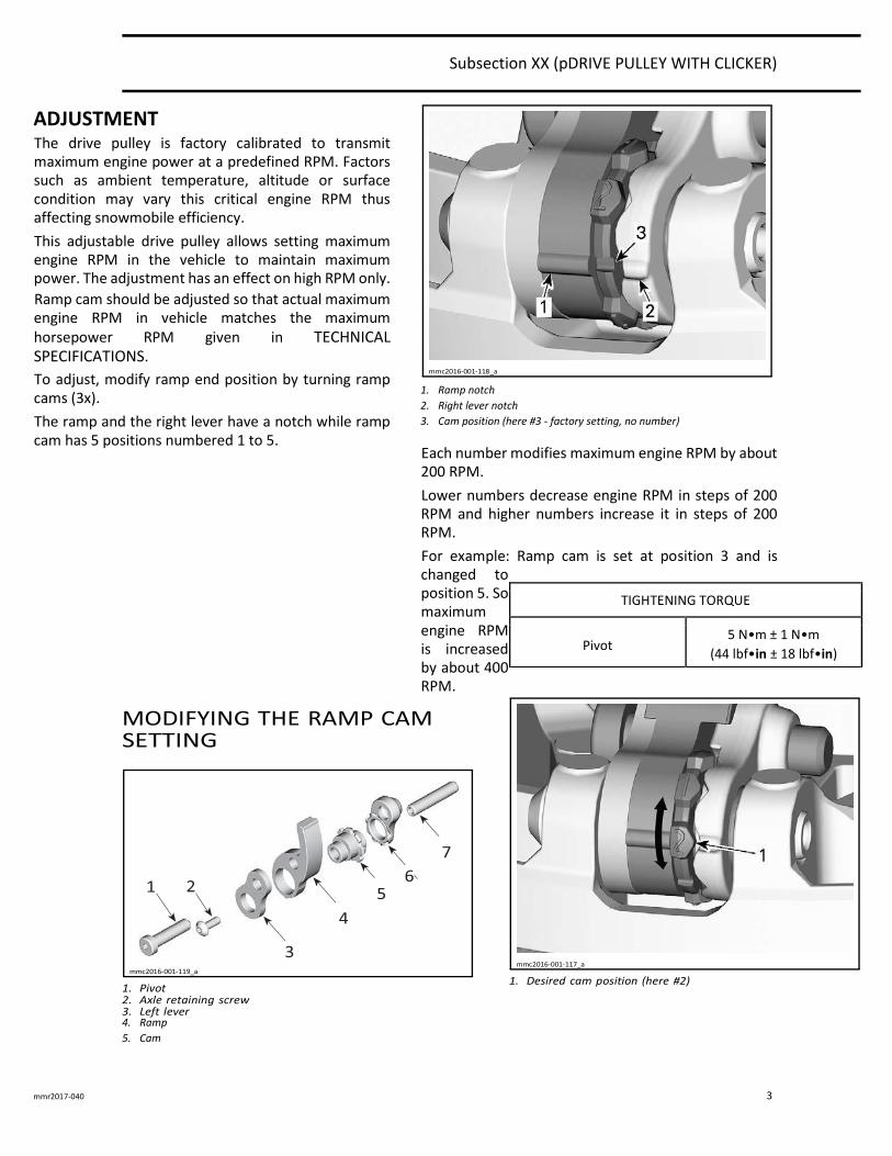
ADJUSTMENT The drive pulley is factory calibrated to transmit maximum engine power at a predefined RPM. Factors such as ambient temperature, altitude or surface condition may vary this critical engine RPM thus affecting snowmobile efficiency.
This adjustable drive pulley allows setting maximum engine RPM in the vehicle to maintain maximum power. The adjustment has an effect on high RPM only.
Ramp cam should be adjusted so that actual maximum engine RPM in vehicle matches the maximum horsepower RPM given in TECHNICAL SPECIFICATIONS.
To adjust, modify ramp end position by turning ramp cams (3x).
The ramp and the right lever have a notch while ramp cam has 5 positions numbered 1 to 5.
1. Ramp notch 2. Right lever notch 3. Cam position (here #3 - factory setting, no number)
Each number modifies maximum engine RPM by about 200 RPM.
Lower numbers decrease engine RPM in steps of 200 RPM and higher numbers increase it in steps of 200 RPM.
For example: Ramp cam is set at position 3 and is changed to position 5. So maximum engine RPM is increased by about 400 RPM.
4. Ramp 5. Cam
TIGHTENING TORQUE
Pivot 5 N•m ± 1 N•m
(44 lbf•in ± 18 lbf•in)
Subsection XX (pDRIVE PULLEY WITH CLICKER)
4 mmr2017-040
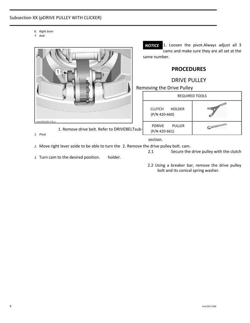
6. Right lever 7. Axle
1. Loosen the pivot.Always adjust all 3
cams and make sure they are all set at the
same number.
PROCEDURES
DRIVE PULLEY
Removing the Drive Pulley
1. Remove drive belt. Refer to DRIVEBELTsub- 1. Pivot
section.
2. Move right lever aside to be able to turn the 2. Remove the drive pulley bolt. cam. 2.1 Secure the drive pulley with the clutch
3. Turn cam to the desired position. holder.
2.2 Using a breaker bar, remove the drive pulley bolt and its conical spring washer.
NOTICE
REQUIRED TOOLS
CLUTCH HOLDER
(P/N 420-660)
PDRIVE PULLER
(P/N 420-661)
Subsection XX (pDRIVE PULLEY WITH CLICKER)
mmr2017-040 5
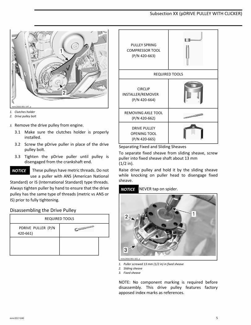
1. Clutches holder 2. Drive pulley bolt
3. Remove the drive pulley from engine.
3.1 Make sure the clutches holder is properly installed.
3.2 Screw the pDrive puller in place of the drive pulley bolt.
3.3 Tighten the pDrive puller until pulley is disengaged from the crankshaft end.
These pulleys have metric threads. Do not
use a puller with ANS (American National
Standard) or IS (International Standard) type threads.
Always tighten puller by hand to ensure that the drive
pulley has the same type of threads (metric vs ANS or
IS) prior to fully tightening.
Disassembling the Drive Pulley
REQUIRED TOOLS
PDRIVE PULLER (P/N
420-661)
PULLEY SPRING COMPRESSOR TOOL
(P/N 420-663)
REQUIRED TOOLS
CIRCLIP INSTALLER/REMOVER
(P/N 420-664)
REMOVING AXLE TOOL
(P/N 420-662)
DRIVE PULLEY OPENING TOOL (P/N 420-665)
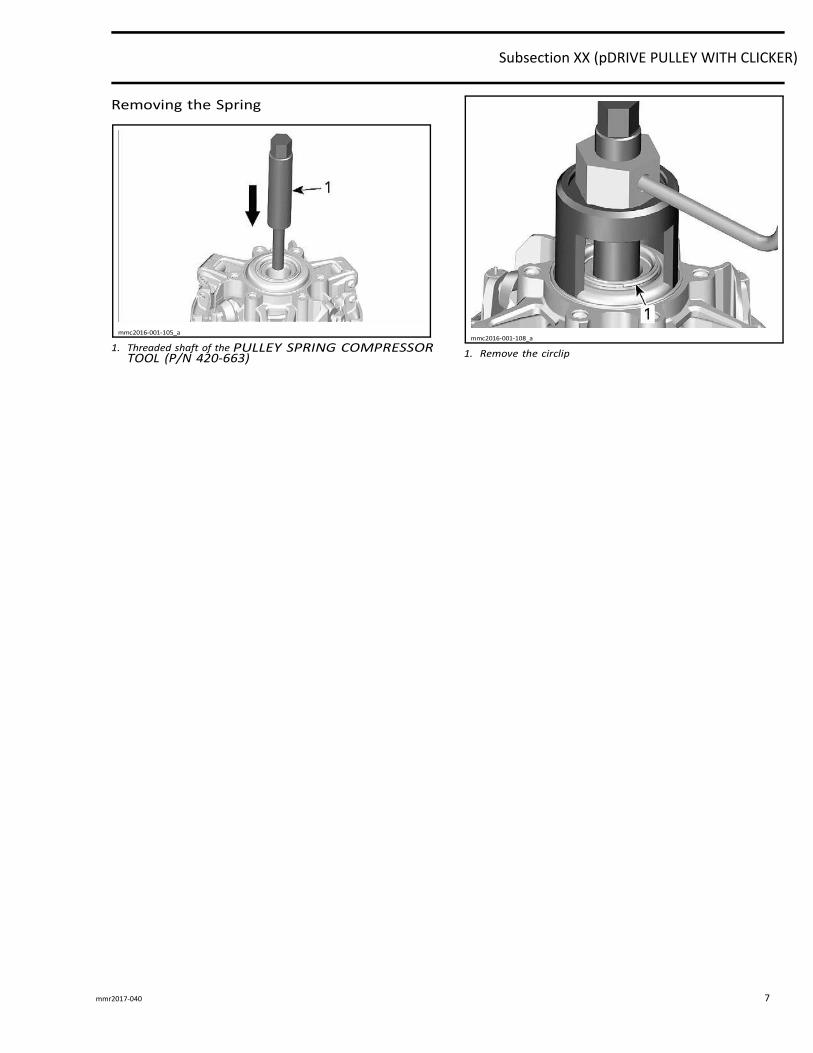
Separating Fixed and Sliding Sheaves
To separate fixed sheave from sliding sheave, screw puller into fixed sheave shaft about 13 mm (1/2 in).
Raise drive pulley and hold it by the sliding sheave while knocking on puller head to disengage fixed sheave.
NEVER tap on spider.
1. Puller screwed 13 mm (1/2 in) in fixed sheave 2. Sliding sheave 3. Fixed sheave
NOTE: No component marking is required before disassembly. This drive pulley features factory apposed index marks as references.
NOTICE
NOTICE
Subsection XX (pDRIVE PULLEY WITH CLICKER)
6 mmr2017-040
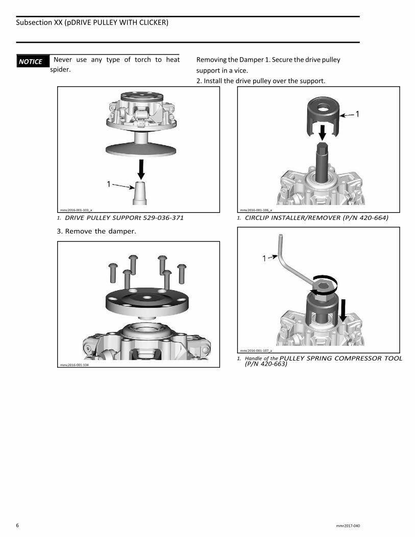
Never use any type of torch to heat
spider.
Removing the Damper 1. Secure the drive pulley
support in a vice.
2. Install the drive pulley over the support.
NOTICE
Subsection XX (pDRIVE PULLEY WITH CLICKER)
mmr2017-040 7
Subsection XX (pDRIVE PULLEY WITH CLICKER)
8 mmr2017-040
Subsection XX (pDRIVE PULLEY WITH CLICKER)
mmr2017-040 9
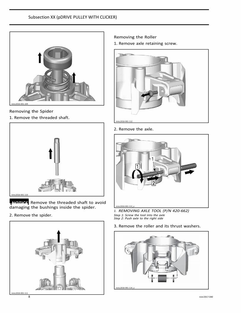
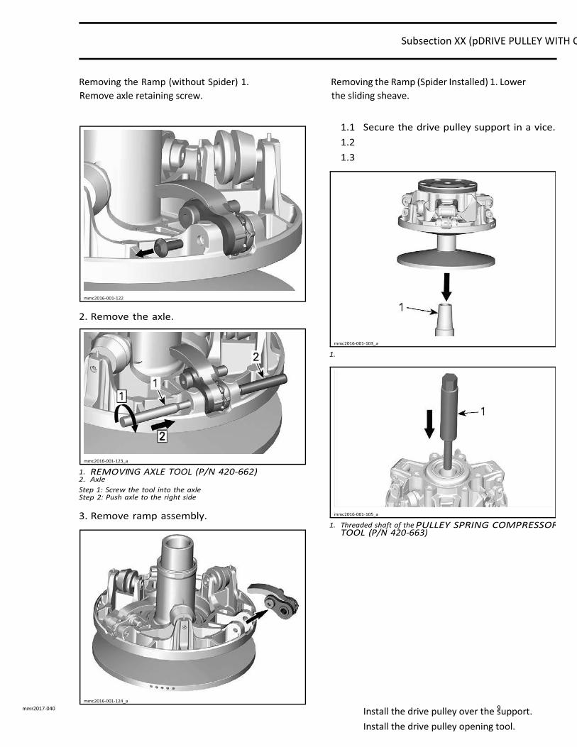
Removing the Ramp (without Spider) 1.
Remove axle retaining screw.
Removing the Ramp (Spider Installed) 1. Lower
the sliding sheave.
Install the drive pulley over the support.
Install the drive pulley opening tool.
Subsection XX (pDRIVE PULLEY WITH CLICKER)
10 mmr2017-040
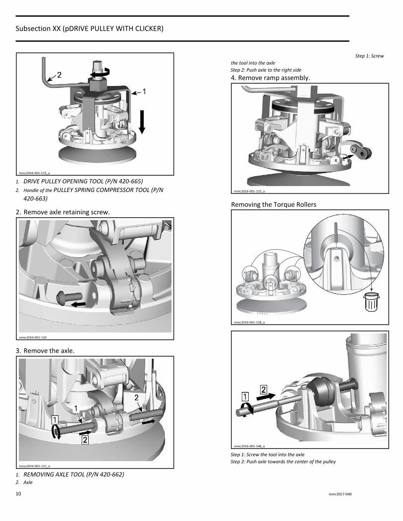
1. DRIVE PULLEY OPENING TOOL (P/N 420-665) 2. Handle of the PULLEY SPRING COMPRESSOR TOOL (P/N
420-663)
2. Remove axle retaining screw.
3. Remove the axle.
1. REMOVING AXLE TOOL (P/N 420-662) 2. Axle
Step 1: Screw
the tool into the axle Step 2: Push axle to the right side 4. Remove ramp assembly.
Removing the Torque Rollers
Step 1: Screw the tool into the axle Step 2: Push axle towards the center of the pulley
Subsection XX (pDRIVE PULLEY WITH CLICKER)
mmr2017-040 11
Replacing the Sliding Sheave Bushing
In case of worn out bushing, it is advisable to replace whole sliding sheave assembly as replacing just the bushing may reduce drive pulley performance.
Cleaning the Drive Pulley NOTE: Parts must be at room temperature before cleaning.
Clean pulley sheaves and shaft with fine steel wool and dry cloth.
Using a paper towel with PULLEY FLANGE
CLEANER (P/N 413 711 809), clean the following components.
– Crankshaft tapered end
– Taper inside fixed sheave of drive pulley
– Crankshaft threads– Retaining screw threads.
Avoid contact between
cleaner and crankshaft seal
because damage may occur.
Remove all hardened oil deposits that are baked on crankshaft and pulley tapered surfaces with coarse or medium steel wool and/or sand paper no. 600.
Do not use any other type of
abrasive.
Reclean mounting surfaces with paper towel and cleaning solvent.
Wipe off the mounting surfaces with a clean, dry paper towel.
Mounting surfaces must be
free of any oil, cleaner or
towel residue.
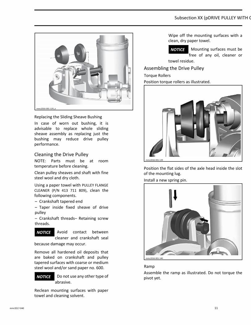
Assembling the Drive Pulley
Torque Rollers
Position torque rollers as illustrated.
Position the flat sides of the axle head inside the slot of the mounting lug.
Install a new spring pin.
Ramp
Assemble the ramp as illustrated. Do not torque the pivot yet.
NOTICE
NOTICE
NOTICE
Subsection XX (pDRIVE PULLEY WITH CLICKER)
12 mmr2017-040
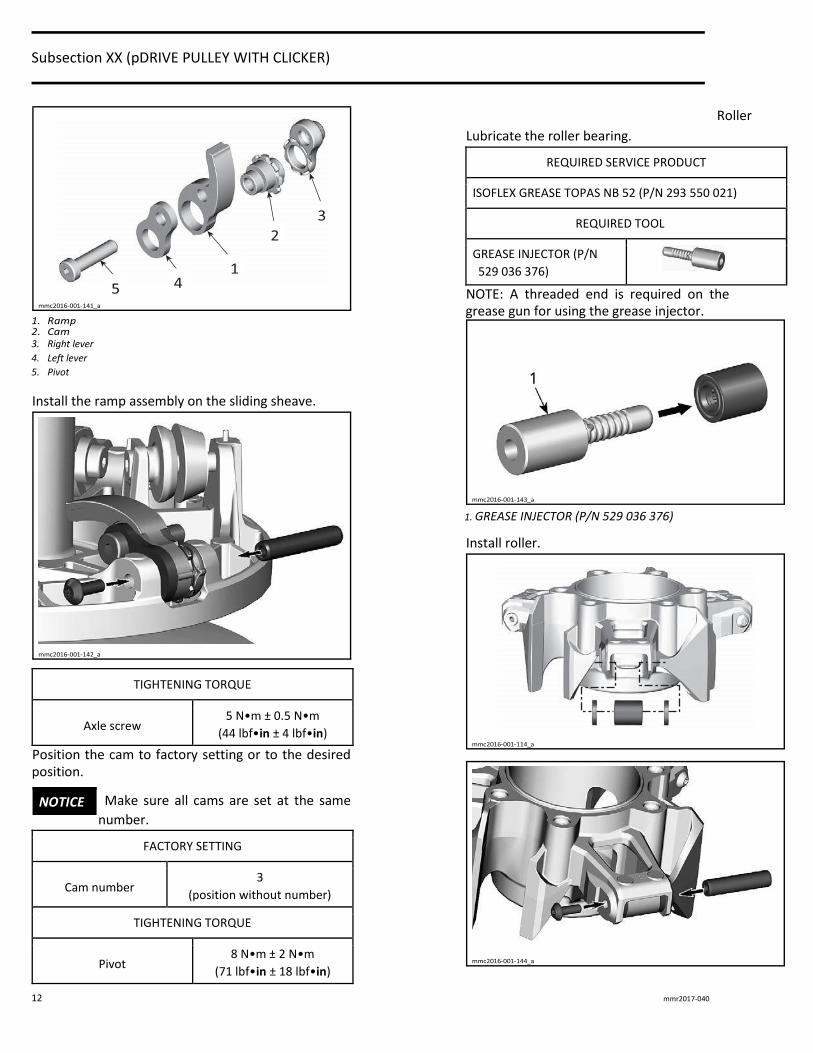
3. Right lever 4. Left lever 5. Pivot
Install the ramp assembly on the sliding sheave.
TIGHTENING TORQUE
Axle screw 5 N•m ± 0.5 N•m
(44 lbf•in ± 4 lbf•in)
Position the cam to factory setting or to the desired position.
Make sure all cams are set at the same
number.
FACTORY SETTING
Cam number 3
(position without number)
TIGHTENING TORQUE
Pivot 8 N•m ± 2 N•m
(71 lbf•in ± 18 lbf•in)
Roller
Lubricate the roller bearing.
REQUIRED SERVICE PRODUCT
ISOFLEX GREASE TOPAS NB 52 (P/N 293 550 021)
REQUIRED TOOL
GREASE INJECTOR (P/N
529 036 376)
NOTE: A threaded end is required on the grease gun for using the grease injector.
1. GREASE INJECTOR (P/N 529 036 376)
Install roller.
NOTICE
Subsection XX (pDRIVE PULLEY WITH CLICKER)
mmr2017-040 13
TIGHTENING TORQUE
Roller axle screw 5 N•m ± 0.5 N•m
(44 lbf•in ± 4 lbf•in)
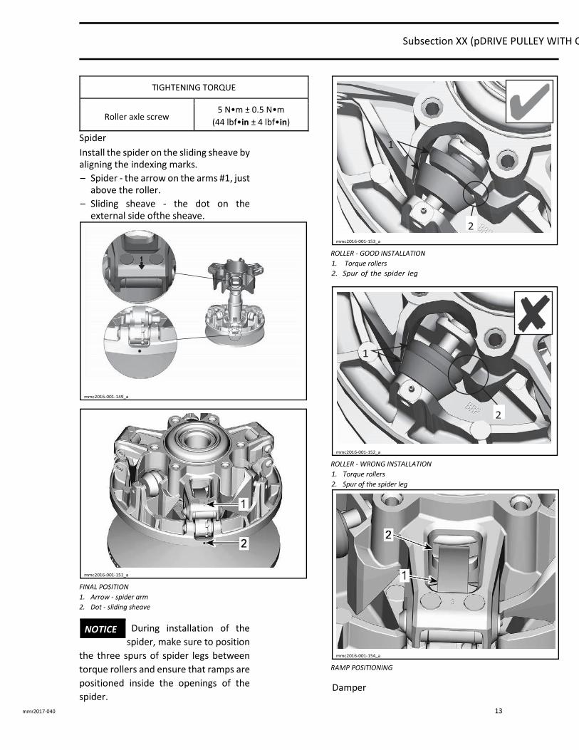
Spider
Install the spider on the sliding sheave by aligning the indexing marks.
– Spider - the arrow on the arms #1, just above the roller.
– Sliding sheave - the dot on the external side ofthe sheave.
FINAL POSITION 1. Arrow - spider arm 2. Dot - sliding sheave
During installation of the
spider, make sure to position
the three spurs of spider legs between
torque rollers and ensure that ramps are
positioned inside the openings of the
spider.
ROLLER - GOOD INSTALLATION 1. Torque rollers
ROLLER - WRONG INSTALLATION 1. Torque rollers 2. Spur of the spider leg
RAMP POSITIONING
Damper
NOTICE
Subsection XX (pDRIVE PULLEY WITH CLICKER)
14 mmr2017-040
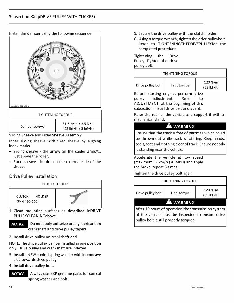
Install the damper using the following sequence.
TIGHTENING TORQUE
Damper screws 31.5 N•m ± 3.5 N•m (23 lbf•ft ± 3 lbf•ft)
Sliding Sheave and Fixed Sheave Assembly
Index sliding sheave with fixed sheave by aligning index marks.
– Sliding sheave - the arrow on the spider arms#1, just above the roller.
– Fixed sheave- the dot on the external side of the sheave.
Drive Pulley Installation
REQUIRED TOOLS
CLUTCH HOLDER
(P/N 420-660)
1. Clean mounting surfaces as described inDRIVE PULLEYCLEANINGabove.
Do not apply antiseize or any lubricant on
crankshaft and drive pulley tapers.
2. Install drive pulley on crankshaft end.
NOTE: The drive pulley can be installed in one position only. Drive pulley and crankshaft are indexed.
3. Install a NEW conical spring washer with its concave side towards drive pulley.
4. Install drive pulley bolt.
Always use BRP genuine parts for conical
spring washer and bolt.
5. Secure the drive pulley with the clutch holder.
6. Using a torque wrench, tighten the drive pulleybolt. Refer to TIGHTENINGTHEDRIVEPULLEYfor the completed procedure.
Tightening the Drive Pulley Tighten the drive pulley bolt.
TIGHTENING TORQUE
Drive pulley bolt First torque 120 N•m (89 lbf•ft)
Before starting engine, perform drive pulley adjustment. Refer to ADJUSTMENT, at the beginning of this subsection. Install drive belt and guard.
Raise the rear of the vehicle and support it with a mechanical stand.
WARNING
Ensure that the track is free of particles which could
be thrown out while track is rotating. Keep hands,
tools, feet and clothing clear of track. Ensure nobody
is standing near the vehicle.
Accelerate the vehicle at low speed (maximum 32 km/h (20 MPH) and apply the brake, repeat 5 times.
Tighten the drive pulley bolt again.
TIGHTENING TORQUE
Drive pulley bolt Final torque 120 N•m (89 lbf•ft)
WARNING
After 10 hours of operation the transmission system
of the vehicle must be inspected to ensure drive
pulley bolt is still properly torqued.
NOTICE
NOTICE