Embed Size (px)
Citation preview

Non-Silicone, Thermal Interface Materials
protect the heart of technology

P R O T E C T T H E H E A RT O F T E C H N O LO GY
ABOUT AOS
history
At AOS Thermal Compounds LLC, our roots trace back to Newark, New Jersey in 1895 and the founding of American Oil & Supply Co. AOS was a major supplier of lubricant products to the military in both World Wars and a pioneer in the development of turbine and hydraulic lubricants based on synthetic esters for aircraft, naval vessels and NASA.
Our Mission
Our focus is thermal grease, and making it user-friendly. Our mission is to be the leading innovator in solving thermal interface challenges
are focused, enthusiastic and committed contributors to a business driven by clients and product innovation.
Product Development
can demonstrate superior shelf-life stability, long term performance and optimal rheological properties. AOS Thermal Compounds has added new analytical and testing capabilities to streamline our product development and quality control activities. We also employ statistical experimental design and molecular modeling in our product development methodology.
We are constantly striving to bring better solutions to the individual customer’s thermal management needs in today’s demanding environment.
2
3
SERVICES
Custom Formulation
AOS Thermal Compounds approaches our product development from a materials science perspective. We have combined knowledge gained from our experience in synthetic lubricants, metal oxide and ceramic
demands of the thermal management market. We also have active programs to customize our existing products to meet individual customer needs.
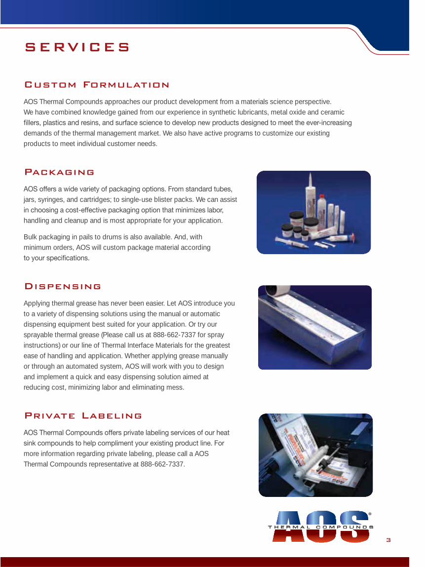
Packaging
jars, syringes, and cartridges; to single-use blister packs. We can assist
handling and cleanup and is most appropriate for your application.
Bulk packaging in pails to drums is also available. And, with minimum orders, AOS will custom package material according
Dispensing
Applying thermal grease has never been easier. Let AOS introduce you to a variety of dispensing solutions using the manual or automatic dispensing equipment best suited for your application. Or try our sprayable thermal grease (Please call us at 888-662-7337 for spray instructions) or our line of Thermal Interface Materials for the greatest ease of handling and application. Whether applying grease manually or through an automated system, AOS will work with you to design and implement a quick and easy dispensing solution aimed at reducing cost, minimizing labor and eliminating mess.
Private Labeling
more information regarding private labeling, please call a AOS Thermal Compounds representative at 888-662-7337.

P R O T E C T T H E H E A RT O F T E C H N O LO GY
4
TERMINOLOGY
1. Heat Sink Compound: a heated surface and the surface of a heat sink. It aids or speeds up the removal of heat from original surface
increased.
2. Viscosity:
3. Rheology: applied force. They tend to be Newtonian or thixotropic in nature.
4. Newtonian Flow: independent of the shear force applied. The viscosity does not change in response to an applied force (stress).
5. Thixotropic:
butter, and mayonnaise.
6. Bond Line: The limiting or minimum thickness that an interface material where a minimum thermal resistance is achieved. The thermal resistance will not change at thicknesses less than this value.
7. Dielectric strength:
the dielectric strength of a material, the less able it is to conduct an electrical current. A common accepted measurement technique is the ASTM D 149 method.
8. Electrically conductive: to conduct an electric current. Most pastes are magnitudes less electrically conductive than metallic copper or
metallic particles are essentially electically non-conductive compared to copper wires and vias. Problems arise when metal particle containing pastes break down and particles migrate onto the surfaces of devices causing short circuits.
9. Outgassing: Refers to trapped gas being released from a solid when it is heated and/or placed under a vacuum.
of a vacuum of 10-5 torr, at 100 oC, for 24 hours. The collected volatile condensed material (cvcm) and the total mass loss (tml) are measured using this method.
10. Units of Thermal Conductivity: Currently given in W/m-K (Watts/meter-degree Kelvin). Older literature values may be reported in cal/(cm2)/sec/cm/o oC = 394 W-m/K.
11. Pump Out: This is a phenomenon that occurs with lower viscosity materials, such as thermal greases, where the interface material appears to ooze or migrate out from between two surfaces after a period of use. It is believed to occur because the material is successively stressed mechanically due to changes in temperature. As a result,
Small mechanical deformations occur when electrical current passes through the device.

MIR
OPHASE
5
THERMAL MEASUREMENTS
Thermal Conductivity vs Thermal Resistance
It is critically important to understand the difference between bulk conductivity (W/mK) and contact resistance (°C/W) to fully understand overall thermal performance when selecting thermal interface materials (TIM's). Bulk thermal conductivity is a measurable physical property of a material much like boiling point, where thermal resistance is a measurement of heat transfer across a construction of interfaces from point A to point B. Quite often engineers look for the most conductive TIM without regard for other properties such as wetting and bond line thickness (BLT). Material rheology, modulus, filler size, shape and content all play a critical role in determining improved surface wetting and BLT. Ideally a TIM for low BLT will fully wet, but allow intimate contact of the adjoining surfaces (where the best heat transfer takes place), and then displace the air and fill the microscopic voids. Therefore, a modest bulk thermal conductivity TIM may exhibit a lower thermal resistance than a high conductivity TIM that may have poor wetting and/or large particles. However, high thermal conductivity becomes much more important for thick grease applications or gap fillers where there is no intimate contact of the adjoining surfaces and the heat must travel a longer path through the TIM. Note: Thermal Impedance incorporates area into the thermal resistance calculation and is expressed as °C in2/W or °C cm2/W.
2.1.
1. ASTM-D5479: Tests thermal conductivity2. ORACLE® 270-7806-01 TTV: Tests thermal resistance
Terminology

P R O T E C T T H E H E A RT O F T E C H N O LO GY
6
TESTING METHODS
ASTM-D5470-06: Lab controlled thermal resistance tester used for determining TIM bulk thermal conductivity (W/mK).
This is a steady state method of determining the thermal conductivity of
thermal impedance) for a material, at a given thickness, is determined by placing the paste at the interface between equilibrated hot and cold blocks.
temperature gradient set up between the two blocks at steady state. The temperatures are determined at set placements along
.
40
ºF
Time (minutes)
ASTM D-5470-06 TYPICAL TEMPERATURE
PROFILE FOR 6 THERMAL COUPLES
160
140
120
100
80
60
200 40 60 80
T6
T2
T3
4
T1
T5
0.00
ºC(c
m)2 /
W
Gap Width (mil)
THERMAL RESISTANCE VALUES @ 50ºC
8.00
6.00
7.00
5.00
4.00
3.00
2.00
1.00
105 150.0 20
AOS 521371.2 W/m-K
Leading Silicone0.6 W/m-K
Thermal conductivity for a material is determined (back calculation) by determining the inverse of the slope of the graph of several thermal impedances (resistances) at various thicknesses. The graph below shows the results taken at 1, 2, 5 and 20 mils (0.001” = mil).

MIR
OPHASE
7
the die corresponding to an average resistance measurement is determined using a calibration chart. The chart is developed from die resistances recorded at a number of set temperatures as shown below.
also. The resistance is determined using the fundamental equation (Tr –Ths)/ P.
0
Tem
pera
ture
(ºC)
ohm
CALIBRATION CURVE FOR 7806 CELL 2,2D
120
100
80
60
40
20
120110 130100 140 150 160
TESTING METHODS
ORACLE® 270-7806-01 TTV: In situ thermal resistance tester for determining comparative TIM thermal performance in “real world” integrated circuits.
The Thermal Test Vehicle (TTV) is used to provide a thermal resistance on a device that is closer to real-world applications. It consists of a ca. 1” x 1” bare silicone die and a copper heat sink. The copper heat sink has an embedded T type thermocouple that measures the temperature of the heat sink. The silicone die has 34 thermal sensors across the area of a die that measure the resistances in response to the build up of heat. 0.5 grams of thermal grease is applied between the die and heat sink and a uniform power is supplied across the die. The resistances of an area on the die and the heat sink temperature are recorded after the power is applied and temperature equilibrium is established. The temperatures and resistances
Testing M
ethods

P R O T E C T T H E H E A RT O F T E C H N O LO GY
8
COMPETITIVE ANALYSIS
The thermal resistance is often of greater importance than the thermal conductivity for determining
AOS MATERIALS TESTED AGAINST LEADING COMPETITION
Material
Company Agray siliconethermal grease
AOS 52137
Company Bgray siliconethermal grease
Company Cover-clocker grease
AOS 54011(High Temp)
Company Bgray siliconethermal grease
AOS 52070
AOS MICRO-FAZE®
(Thermal Pad)
Company Astandard white silicone grease
Company Dtypical PCM(Thermal Pad)
Thermal Resistance Rank
1
2
2
3
4
5
6
8
7
9
Thermal Conductivity Rank
3
5
2
4
6
2
1
N/A
7
N/A
Thermal Conductivity W/m-K
2.8
3.6
1.2
4.4
0.7
N/A
1.2
0.9
6.0
N/A
Thermal Resistance oC/W
0.032
0.035
0.038
0.046
0.054
0.114
0.035
0.041
0.048
0.062

MIR
OPHASE
9
PRODUCT STABILITY
Company A: Standard White Thermal Grease
After 300 cycles: Thermal grease voids and pumps out
After 300 cycles: Remains tacky with zero pump out
After 300 cycles: Remains tacky with zero pump out
AOS 52137 Thermal Grease
AOS MicroFaze 3A4 Thermal Pad
Product S
tability

P R O T E C T T H E H E A RT O F T E C H N O LO GY
10
Product Description
® is a new, revolutionary thermal interface
in a thermal interface without the mess of grease. ® does not require burn-in to form into place.
Technical Advantages
Low thermal resistance with minimum force Naturally tacky, non-silicone
No phase change required for heat transfer to take place—
Durable resistance over usable lifetime
What is MICRO-FAZE®?
Initial good oC/W (Thermal Resistance) is no longer Enough...
RESISTANCE OVER USABLE LIFETIME
IS NOW ESSENTIAL
0.8 mil greaseA Based on Aluminum Carrier
(2.0 W/m-K @ 55ºC)
(5.0 W/m-K @ 55ºC)
2.0 mil aluminum
0.8 mil grease
1.8 mil greaseK Kapton MT whereelectrical resistance is required
(1.0 W/m-K @ 55ºC)
2.0 mil Kapton
1.8 mil grease
MICRO-FAZE is NOT a
phase change material

MIR
OPHASE
11
Features & Benefits
Retains all the performance advantages of thermal grease but in the form of a thermal pad
Requires minimum force to achieve total interface contact
interface contact
Heat transfer takes place at any temperature (unlike phase change materials), making ® an excellent choice for cold plate applications
Is a “drop-in-place” product that is easy to use and handle in a manufacturing environment
penalize thermal resistance
Used in All Electronics Cooling Assemblies
MICRO-FAZE is NOT aphase change material
IGBT Uninterrupted Power Supply
MIC
RO
-FAZE
®

P R O T E C T T H E H E A RT O F T E C H N O LO GY
12
Thermal Grease Performance in a Thermal Pad
® performs well at any temperature and minimal pressure
ASTMD 5470-06 thermal resistance values at pressures ranges from 10psi to 100psi
Samples After Thermal Shock Stability (0—165˚C @ 10 min Dwell)
0.05
0.00
0.10
0.15
0.20
0.25
0.30
ºC /W
Pressure (psi)
MICROFAZE® SERIES AT 55ºC
4020 600.0 80 100 120
MicroFaze A6
Leading Silicone-basedThermal Grease
MicroFaze A4MicroFaze 3A4
® 3A4-52062 after 150 thermal cycles
Remains tacky with zero pump out
Leading phase-change material after 20 thermal cycles
Contact lost; dried out

13
115
108
99
90
81
72
63
54
45
36
30ºC
115
108
99
90
81
72
63
54
45
36
30ºC
115
108
99
90
81
72
63
54
45
36
30ºC
115
108
99
90
81
72
63
54
45
36
30ºC
Independent Material Testing
Experiment: Summary: Grease performed best; Micro-faze 3 A4 slightly
better than leading Phase Change material
THERMAL IMAGING DETAILS Sample Tested @ several torques and power settings on a 12 pin 44 x 33 mm SiC module
oC @ 231 watts
Initial oC, respectively at 12 in-lb torque
AOS MICRO-FAZE 3A4 Leading Phase Change
Phase change degredation and pump out lead to over-heating and component failure
Performance maintained over time

P R O T E C T T H E H E A RT O F T E C H N O LO GY
14
How MICRO-FAZE® Works
® grease is comparable to leading CPU grease
Pad form demonstrates superior resistance to leading CPU thermal grease
ºC /W
Time (minutes)
THERMAL TESTER
RESISTANCE RESPONSE
0.5
0.4
0.3
0.2
0.1
0.0030 4010 20 500 60 9080 12010070 140
2 mil gapMF3A4-52062Leading silicone grease
ºC /W
Time (minutes)
MICROFAZE® RESISTANCE
0.12
0.09
0.06
0.03
0.0040 6020 40 800.0 120 160140 180
MF3A4 Pad@ 40 psi
Leading silicone grease @ 100 psi

15
Configuration
® thermal pads are supplied in bulk rolls, sheets, individual die-cut parts or kiss-cut rolls with pull tabs for ease of application.
Bulk rolls and sheets Kiss cut with tabs
PHYSICAL PROPERTIES A4 A6 K 3A4
Substrate Aluminum Aluminum Kapton® Aluminum
Substrate Thickness, in. 0.002 0.002 0.002 0.002
Compound Thickness/side in. 0.001 0.002 0.002 0.001
Total Thickness, in. 0.004 0.006 0.006 0.004
THERMAL PROPERTIES
Thermal Resistance, 0.20-0.10 0.25-0.18 0.55-0.48 0.08-0.039@ 55°C in2/W 10 PSI to70 PSI Test Method: ASTM D-5470 modified
Dielectric Strength, 2000 (12000) V/mil VAC Test Method: ASTM D-149
Dielectric Constant, 3.7@ 1 KHz Test Method:ASTM D-150
Volume Resistivity, 1.01x10¹⁵ohm-cm ASTM D-257
MICROFAZE® PROPERTIES

P R O T E C T T H E H E A RT O F T E C H N O LO GY
Product Description
SURE-FORM® Non-Silicone Thermally Conductive Gap
demand in electronics for increased thermal transfer
and the space between surfaces is uneven.
SURE-FORM® is highly conformable and is an excellent
without the limitations in application and handling.
Technical Advantages
Naturally tacky and reworkable (in sheet form)
What is SURE-FORM®?
52153 PUTTY
3.5 W/m-K 36 oC 1-part dispensable
52070 PUTTY
6.0 W/m-K @ 36 oC 1-part dispensable
52041 SHEET
2.2 W/m-K @ 36 oC 60 – 250 mil thickness
Conformable
Clay-like material Available in sheet form
One-part dispensable High thermal conductivity
Highest performance,
16

MIR
OPHASE
17
Features & Benefits
SURE-FORM®
SURE-FORM® where minimum stress is placed on components
SURE-FORM® will conform to any shape and/or size of a component enabling complete physical contact,
The natural tackiness of SURE-FORM® allows two surfaces to be in contact with minimum pressure
Suggested Applications
SURE-FORM®’s generating device and heat sink metal chassis
Non-Silicone formula is advantageous for optical applications and high compression loads
SURE-FORM® conducts heat away from individual components and into metal covers, frames or spreader plates
SURE-FORM® interposer plates, laptop PCs, high-density handheld portable electronics, electronic ballasts & various automotive applications
LightingBattery Automotive
SU
RE-FO
RM
®

P R O T E C T T H E H E A RT O F T E C H N O LO GY
18
Competitive performance
ASTMD 5470-06 thermal resistance values at pressures ranges from 10psi to 100psi
0.00
ºC /W
Thickness (mil)
SUREFORM® VS LEADING SILICONE PUTTY
2.40
1.80
2.10
1.50
1.20
0.90
0.60
0.30
2010 300.0 40 50 60
AOS 521533.5 W/mK
AOS 520706.0 W/mK
Gap Filler—41.5 W/mK
@ 36ºC
Samples after 20 thermal shock cycles
SURE-FORM® 52153 unchanged Silicone Putty—
52153 PUTTY
3.5 W/m-K 36 oC 1-part dispensable

19
Distinct Conformability
High Thermal Conductivity
52041 SHEET
2.2 W/m-K @ 36 oC 60 – 250 mil thickness
52153 PUTTY
3.5 W/m-K 36 oC 1-part dispensable
52070 PUTTY
6.0 W/m-K @ 36 oC 1-part dispensable
SURE-FORM® is also available in standard grease form
Highest performance,
SURE-FORM® is available in sheets and can be die-cut to
in thickness from 0.04” (1.0mm) and higher
Naturally tacky and reworkable

P R O T E C T T H E H E A RT O F T E C H N O LO GY
20
Product Description
for AT&T in the early 1970’s, AOS has continued to
thermal greases on the market, all with a design toward ease of use and durability. There is no silver bullet thermal grease that is ideal for every application. This
thin bond line products, to high thermal conductivity
can include water cleanability, thixotropic or Newtonian rheology, customized rheology, little to no pump-out, low outgassing, and high temperature stability.
Silicone vs Non-Silicone
Silicone oils tend to bleed which lends to migration and contamination
Silicone contamination can lead to local component, board, assembly or even plant wide problems with surface
Silicone oil bleed can lead to dry-out, cracking and the formation of air gaps in the interface
tactifying resins and thermoplastic elastomers
Non-silicone thermal greases remain tacky and in place for the operational life or your hardware
100 thermal shock cycles, 165ºC to 0ºC
Silicone grease voids and pumps out AOS Non-silicone; no voids or pump-out

MIR
OPHASE
21
Features & Benefits
Non-silicone; non-curing
Resists pump-out
Water cleanable options; no mess, no solvents required
Low bond line for lowest resistance
High dielectric strength
Non-hazardous; biodegradable
Customized rheology
Used in any device where efficient cooling is required
TH
ER
MAL G
REAS
E

P R O T E C T T H E H E A RT O F T E C H N O LO GY
CONVERSION CHART
mil x 25.4 micron
mil x 0.0254 mm
mm x 39.37 mil
in2 x 6.451 cm2
psi x 0.06895 bar
psi x 0.00690 MPa
psi x 0.07031 kg(f)/cm2
oC x 1.8 + 32 oF
CONTACT US Toll Free: (888)-662-7337
Phone: (732)-389-5514
Fax: (732)-389-6380
E-mail:[email protected]
www.aosco.com
® is a registered trademark of AOS Thermal Compounds and is patent #6,475,962 B1.® is a registered trademark of AOS Thermal Compounds.
© 2012 AOS Thermal Compounds. All rights reserved.
with minimum force —naturally tacky required for heat transfer to take place over usable lifetime


![Silicone Solutions for thermal management · 7 Thermally Conductive Dispensable Silicone Pads and Pastes Product Thermal Conductivity [W/mK] Type Viscosity D = 10 1/s [Pa.s] Hardness,](https://img.pdfslide.us/doc/110x75/5ec57351f2cf1c63373094ad/silicone-solutions-for-thermal-management-7-thermally-conductive-dispensable-silicone.jpg)