Embed Size (px)
Citation preview
Morphology of copper nanoparticles in a nitrogen atmosphere: A first-principles investigation
Aloysius Soon,1,* Lindee Wong,1 Bernard Delley,2 and Catherine Stampfl1
1School of Physics, The University of Sydney, Sydney, New South Wales 2006, Australia2Paul-Scherrer-Institut, WHGA/123, CH-5232 Villigen PSI, Switzerland
�Received 26 December 2007; published 24 March 2008; publisher error corrected 28 March 2008�
We perform first-principles density-functional-theory calculations to determine the stability and associatedphysical and electronic properties of different adsorption phases of N on Cu �100� and Cu �110� substrates forcoverages ranging from 0.125 to 1 monolayer �ML�. For N on Cu �100�, we consider adsorption in fourfoldhollow sites while for N on Cu �110�, we consider various adsorption sites including N-induced missing-rowsurface reconstructions and the surface nitridelike, “pseudo-�100�” reconstruction. We report the atomic andelectronic structure and compare with analogous results for N/Cu �111�. By combining results from ourprevious study of the N/Cu �111� system with the current investigations, we predict the possible morphology ofa Cu crystal in different nitrogen environments by performing a Wulff construction at appropriate chemicalpotentials of nitrogen. We also find that all low-energy N/Cu surface structures—namely, Cu �100�-c�2�2�-N and the surface nitrides found on Cu �110� and Cu �111�—share a common geometric feature: i.e.,surface nanopatterns resembling 1 atomic layer of Cu3N �100�. These nanopatterned structures exist for anarrow range of nitrogen chemical potentials before the onset of bulk Cu3N, unless kinetically hindered. Thisqualitative behavior of the predicted formation of thin-surface nitridelike structures prior to the bulk nitridematerial is very similar to that for transition-metal surfaces in an oxygen atmosphere, where surface oxidelikestructures are predicted to be thermodynamically stable prior to bulk oxide formation.
DOI: 10.1103/PhysRevB.77.125423 PACS number�s�: 68.35.Md, 68.35.B�, 68.35.�p, 05.70.Np
I. INTRODUCTION
Understanding the interaction between N and Cu surfacesis important as copper-based catalysts are widely used insystems containing nitrogen—for example, the reductionand decomposition of nitrogen oxides1–3 and the oxy-dehydrogenation �i.e., oxidation� of ammonia.4,5 With regardto the oxidation of ammonia, NH3, it has been proposed thatcopper oxide is not the active material as had been reportedearlier,5 but copper nitride or a mixed Cu3N /Cu2Ostructure.4 Furthermore, N-modified Cu �100�, Cu �110�, andCu �111� surfaces have been used in the nanostructure fabri-cation of Ag nanowires and Co nanowires and nanodots,6–9
often acting as a template for well-controlled patternedgrowth of these low-dimensional metallic structures.
These applications have motivated a number of experi-mental studies of nitrogen adsorption on low-index coppersurfaces. Under ambient temperatures and pressures, molecu-lar nitrogen does not interact with Cu surfaces, due to thestrong nitrogen-nitrogen bond, so the adsorption of nitrogenon Cu �100�, Cu �110�, and Cu �111� surfaces has beenachieved typically by nitrogen-ion bombardment.10–12 Theseexperimental investigations have resulted in a number of ob-served adsorption phases, from simple chemisorption tocomplex surface nitride structures, which have a thickness onthe nanometer or subnanometer scale.13
For the N/Cu �100� system, both experimental6–9,12,14–16
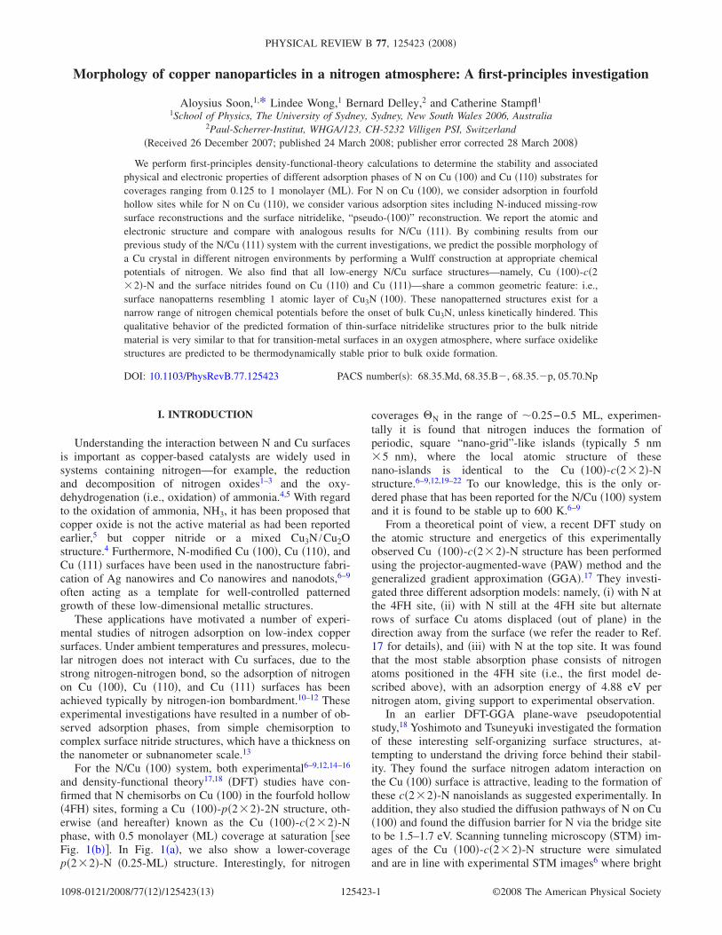
and density-functional theory17,18 �DFT� studies have con-firmed that N chemisorbs on Cu �100� in the fourfold hollow�4FH� sites, forming a Cu �100�-p�2�2�-2N structure, oth-erwise �and hereafter� known as the Cu �100�-c�2�2�-Nphase, with 0.5 monolayer �ML� coverage at saturation �seeFig. 1�b��. In Fig. 1�a�, we also show a lower-coveragep�2�2�-N �0.25-ML� structure. Interestingly, for nitrogen
coverages �N in the range of �0.25−0.5 ML, experimen-tally it is found that nitrogen induces the formation ofperiodic, square “nano-grid”-like islands �typically 5 nm�5 nm�, where the local atomic structure of thesenano-islands is identical to the Cu �100�-c�2�2�-Nstructure.6–9,12,19–22 To our knowledge, this is the only or-dered phase that has been reported for the N/Cu �100� systemand it is found to be stable up to 600 K.6–9
From a theoretical point of view, a recent DFT study onthe atomic structure and energetics of this experimentallyobserved Cu �100�-c�2�2�-N structure has been performedusing the projector-augmented-wave �PAW� method and thegeneralized gradient approximation �GGA�.17 They investi-gated three different adsorption models: namely, �i� with N atthe 4FH site, �ii� with N still at the 4FH site but alternaterows of surface Cu atoms displaced �out of plane� in thedirection away from the surface �we refer the reader to Ref.17 for details�, and �iii� with N at the top site. It was foundthat the most stable absorption phase consists of nitrogenatoms positioned in the 4FH site �i.e., the first model de-scribed above�, with an adsorption energy of 4.88 eV pernitrogen atom, giving support to experimental observation.
In an earlier DFT-GGA plane-wave pseudopotentialstudy,18 Yoshimoto and Tsuneyuki investigated the formationof these interesting self-organizing surface structures, at-tempting to understand the driving force behind their stabil-ity. They found the surface nitrogen adatom interaction onthe Cu �100� surface is attractive, leading to the formation ofthese c�2�2�-N nanoislands as suggested experimentally. Inaddition, they also studied the diffusion pathways of N on Cu�100� and found the diffusion barrier for N via the bridge siteto be 1.5–1.7 eV. Scanning tunneling microscopy �STM� im-ages of the Cu �100�-c�2�2�-N structure were simulatedand are in line with experimental STM images6 where bright
PHYSICAL REVIEW B 77, 125423 �2008�
1098-0121/2008/77�12�/125423�13� ©2008 The American Physical Society125423-1
features of the Cu �100�-c�2�2�-N structure correspondedto N adatoms.
Concerning nitrogen adsorption on Cu �110�, early low-energy electron diffraction �LEED� studies find aCu �110�-p�2�3�-4N surface nitridelike structure formsover the substrate, consisting of an almost squareCu �100�-c�2�2�-N mesh.23–29 This structure has a nitrogencoverage of 0.66 ML and is shown in Figs. 1�e� and 1�f�. TheCu �110�-p�2�3�-4N structure is structurally reconstructedand geometrically different from simple chemisorbed phases.For this work, it will be referred to as a surface nitride.
Other surface reconstruction models have been proposedin the literature for the �2�3� phase, including a “�001�missing-row structure,”30 which we will refer to hereafter asthe “Cu �110�-p�2�3�-2N” model, and a “�110� missing-row structure,”31 which we will refer to hereafter as the“Cu �110�-p�2�3�-N” model. Cu �110�-p�2�3�-2N isshown in Fig. 1�c�, with a top layer Cu row in the �001�
direction missing and two nitrogen atoms adsorbed in thelong-bridge �LB� site, resulting in a coverage of 0.33 ML.For the Cu �110�-p�2�3�-N model, a row of Cu atoms inthe �110� direction is removed from the Cu �110� surface,with a nitrogen atom adsorbed in the LB site, resulting in acoverage of 0.17 ML. This structure is shown in Fig. 1�d�. Toour knowledge, other than the p�2�3� phase, no other or-dered surface structures have been reported for N/Cu �110�.To date, there have also been no first-principles investiga-tions performed for N/Cu �110�.
With regard to nitrogen adsorption on Cu �111�, experi-mental evidence shows that a surface nitride structure forms.This surface nitride is proposed to consist of nitrogen atomsadsorbed in the fourfold hollow sites of a pseudo-�100�reconstruction of the Cu �111� surface with a c�2�2� peri-odicity, i.e., a Cu �100�-c�2�2�-N-like mesh forms overthe Cu �111� substrate.10,32–38 A STM study has proposedthat the above-mentioned pseudo-�100� phase on Cu �111�forms a �25�7�3� rectangular commensurate layer on thesubstrate.10
Our recent DFT study of nitrogen adsorption on Cu �111��Ref. 39� is consistent with experimental results,10,32–38 find-ing models of the pseudo-�100� reconstruction to be bothenergetically preferred over other adsorption structures con-sidered, such as on-surface adsorption at fcc or hcp threefoldhollow sites, as well as subsurface adsorption. The most fa-vorable model of the surface nitride reconstruction that weconsidered consisted of a � 2
−308 � surface unit cell, which will
be referred to as the “16” structure �see Figs. 1�g� and 1�h��,since the area of this cell is 16 times larger than that of theprimitive Cu �111� unit cell. In addition, we also investigatedsurface nitride structures with a smaller periodicity: namely,the “4” structure—one with only the outermost layer of Cuatoms reconstructed, 1L-“4” �Figs. 1�i� and 1�j�� and anotherwith the two outermost Cu layers reconstructed, 2L-“4”�Figs. 1�k� and 1�l��. These structures have 4 times the areaof the primitive Cu �111� unit cell and are energetically lessfavorable than the “16” structure. Further details can befound in Ref. 39.
In the present work we present a DFT study of the chemi-sorbed phases of nitrogen on Cu �100� and Cu �110� surfaces,where we consider coverages ranging from 0.125 to 1 ML.For the N/Cu �110� system, we include surface reconstruc-tions involving missing Cu rows in the �110� and�001� directions—i.e., the Cu �110�-p�2�3�-N andCu �110�-p�2�3�-2N structures, respectively, as well as areconstructed Cu �110�-p�2�3�-4N surface nitridelikestructure. Finally, chemisorption structures with N in the4FH, 3FH �i.e., pseudo-threefold-hollow�, �LB�, and shortbridge �SB� sites, on both the ideal Cu �110� surface and thatwith a row of Cu atoms missing in the �110� direction, areconsidered. For Cu �100�, only the most favorable 4FH siteis investigated. For all structures, we examine the electronicproperties, atomic geometries, and their relative energeticstabilities. The findings for the N/Cu �100� and N/Cu �110�structures are compared with the results of our previousstudy of nitrogen adsorption on Cu �111�.39
Knowing that the morphology of a nanoparticle could bea factor responsible for their physical and chemical proper-ties �and thus functionality�, we proceed to investigate the
FIG. 1. �Color online� Atomic geometries of various N/Cusurface structures: �a� and �b� show the top view of Cu �100�-p�2�2�-N and Cu �100�-c�2�2�-N, respectively, and that ofCu �110�-p�2�3�-2N and Cu �110�-p�2�3�-N are depicted in �c�and �d�, respectively. For Cu �110�-p�2�3�-4N, the top and sideviews are shown in �e� and �f�. Top views of �g� the “16” structure,�i� the “4” structure for one Cu-layer reconstruction �i.e., 1L-“4”�,and �k� the “4” structure for the two Cu-layer reconstruction �i.e.,2L-“4”� �with the second-layer Cu atoms highlighted as large dark�red� spheres�. �h�, �j�, and �l� show the corresponding side views ofthese structures. In all figures lighter large �green� spheres representtop-layer Cu atoms �i.e., Cu1L�, darker large �red� spheres representsecond-layer Cu atoms �i.e., Cu2L�, and dark small �blue� spheresrepresent N atoms, with the exception in �e� and �f� where thelighter �green� and darker �red� large spheres are used to differenti-ate the slight rumping seen in the surface nitride layer. The Cusubstrate atoms are shown in pale �gray� large spheres. Note that in�g�–�l�, the top reconstructed Cu layer is shown in smaller darker�green� spheres for clarity.
SOON et al. PHYSICAL REVIEW B 77, 125423 �2008�
125423-2
possible “nanomorphology” of Cu particles under variousnitrogen atmospheres. In particular, having obtained accurateDFT-derived surface energies of these N/Cu low-index sur-face structures, we perform a Wulff construction40 at selectedvalues of the nitrogen-atom chemical potential and explorehow the Wulff polygon changes from nitrogen-lean tonitrogen-rich conditions.
II. METHODOLOGY
The DFT calculations are performed with the DMol3
code, using the generalized gradient approximation �GGA�for the exchange-correlation functional due to Perdew,Burke, and Ernzerhof �PBE�.41 DMol3 is a numericalimplementation which uses a highly efficient local orbitalbasis set. Further details about the code can be foundelsewhere.42,43
The Cu �100� substrate is modeled using a supercell, withnitrogen coverage on both sides of a 9-atomic-layer slab,while the Cu �110� substrate is modeled with 11 atomic lay-ers, preserving inversion symmetry in both surface models.The vacuum region between repeated slabs is 30 Å. Thedouble-� plus polarization �DNP� basis set and a real spacecutoff of 9 bohrs are used for all calculations. Brillouin-zoneintegrations are performed using a �12�12�1� Monkhorst-Pack grid for the Cu �100��1�1� surface unit cell, andequivalent k-point sampling is used for the larger cells. Forthe Cu �110� surface, a �12�6�1� grid is used for the �1�1� surface unit cell and equivalent sampling for largercells—for example, a �6�2�1� grid for the �2�3� surfacecell. For all calculations, the inner three atomic layers ofeach slab are fixed and all other atoms are relaxed until theforces are less than 0.3 mHa/bohr �0.015 eV /Å�. These pa-rameters were chosen to ensure that calculated energies arewell converged, with an estimated numerical uncertainty ofless than 1 mHa �see the Appendix�.
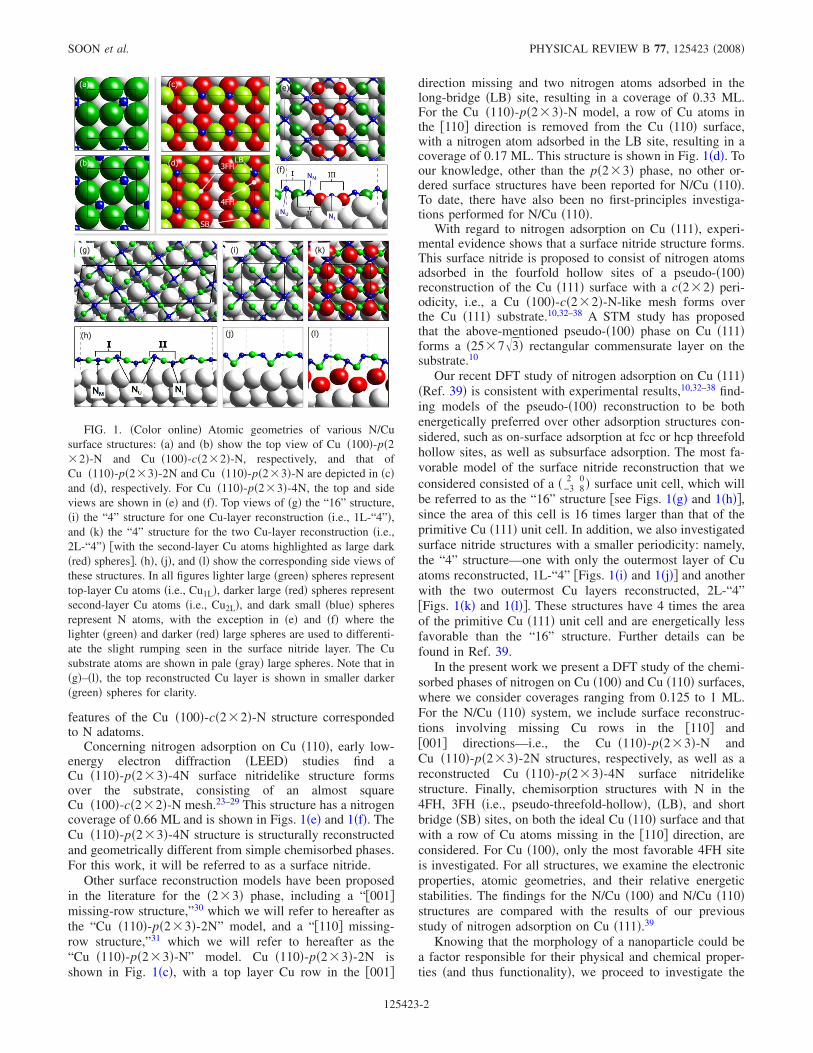
The calculated average binding energies with respect tothe free nitrogen atom �per N atom� are presented in Fig. 2.The binding energy is calculated according the formula
EbN = −
1
NN�EN/Cu − ECu
slab − �NCuECu − NNEN� , �1�
where NN and �NCu are, respectively, the number of nitrogenatoms in the N/Cu system and the difference in the number
of Cu atoms between the N/Cu system and the clean surfaceslab. EN/Cu is the total energy of the N/Cu system, ECu
slab theenergy of the clean slab, ECu the energy of a Cu atom in bulkCu, and EN the energy of a free nitrogen atom from a spin-polarized calculation. The term �NCuECu is only requiredwhen the total number of Cu atoms on the surface is differentfrom that of the clean substrate, as is the case for Cu �110�surface reconstructions and the surface nitride structures onboth Cu �110� and Cu �111�. A positive binding energy indi-cates that the adsorption is exothermic, and a larger bindingenergy indicates a more stable structure.
Using concepts from “ab initio atomisticthermodynamics,”44 we determine the relative stability of theconsidered structures over a range of chemical potentials forthe nitrogen atom. In particular, we calculate the Gibbs freeenergy of adsorption,
�G�T,p� =1
2A�GN/Cu − GCu
slab − �NCu�Cu − NN�N� , �2�
where GN/Cu and GCuslab are the Gibbs free energies of the
N/Cu system and the clean surface, respectively. A is thesurface area of the N/Cu structure, and �N and �Cu are thechemical potentials of the nitrogen and copper atoms. Theterm �NCu�Cu represents the cost of interchanging the Cuspecies with a reservoir of Cu atoms with chemical potential�Cu. This reservoir is taken to be bulk Cu, with which thesurface is assumed to be in equilibrium. For more details, werefer to Refs. 44 and 45. By incorporating Eq. �1� into Eq.�2�, we simplify Eq. �2� to give
�G���N� �1
2A�− NNENb−NN��N� , �3�
where the nitrogen chemical potential is now measured withrespect to the free nitrogen atom, ��N=�N−EN, and we ne-glect contributions due to vibrations and the pressure-volumeterm.44
�� � � �� � �� � � ��� � � � � � � �
�� � � �� � �� � � ��� � � � � � � �
� � �
� � �
� � �
� � �
� � �
� � �
� � �
������ ��� ����������
�� � � �� � �� � � ��� � � � � � � �
� � � � � ! � � � � � " � � � ! � � � � � # � � � ! � � � �
� $ %
& � � ' � ( � )
& � � ' � ( �� � � � � * � + � $ %
& � � ' � ( � �� � � � � * � +
& � � ' � ( � �, ! � - � # � � � � � �
$ � �
% � .
� �
& � � ' � ( � ) )
� � ( / � / , � � ! # � ! �
� � ( / � / , � � ! # � ! �
/ � 0 / , � � ! # � ! �
FIG. 2. �Color online� Calculated average binding energies of N on �a� Cu �100�, �b� Cu �110�, and �c� Cu �111�, for various coveragesof nitrogen and reconstructions. The solid and dashed lines connecting the calculated binding energies are used to guide the eye. In �a�,p�1�1�-NS is the full monolayer N/Cu �100� structure with nitrogen atoms adsorbed on-surface, while p�1�1�-NSS is that with nitrogen-atom subsurface. The values for �c� are taken from Ref. 39.
MORPHOLOGY OF COPPER NANOPARTICLES IN A… PHYSICAL REVIEW B 77, 125423 �2008�
125423-3
III. RESULTS AND DISCUSSION
A. Cu (100) and Cu (110) surfaces, bulk Cu, andthe N2 molecule
The properties of bulk Cu, clean Cu surfaces, and the N2molecule are first considered to ensure that the DFT calcula-tions provide accurate results. The properties of these sys-tems are well known from experimental results as well asfrom other ab initio calculations.
The calculated lattice constant of bulk Cu �neglectingzero-point vibrations� is 3.64 Å, which is in good agreementwith the established experimental value of 3.61 Å.46 TheBrillouin-zone integration for bulk Cu is performed using a�12�12�12� Monkhorst-Pack grid for a �1�1�1� con-ventional cell with real-space radius cutoff of 9 bohrs. Thecomputed bulk modulus and cohesive energy �taking intoaccount the spin-polarization energy for the free Cu atom�are 136 GPa and 3.45 eV, which are in excellent agreementwith the experimental values of 137 GPa and 3.49 eV,46 re-spectively. The minor overestimation of the lattice constantand the underestimation of the bulk modulus are also ob-served in analogous studies of other transition metals.47–49
For the clean Cu �100� surface, the obtained interlayerrelaxations �ij = �dij −d� /d�100% between layers i and j,with respect to the bulk spacing d=1.82 Å, are �12=−2.3% and �23=1.0% for the topmost layers. These resultscorrelate well with other PAW-GGA DFT calculations,17
with �12=−2.6% and �23=0.9% and experimental LEEDdata,50,51 with �12=−2.1% and �23=0.5%. The calculatedwork function for the clean surface is 4.39 eV, which is simi-lar to the reported experimental value of 4.59 eV �Ref. 52�and theoretical value of 4.49 eV �Ref. 17�. We note that it istypical that DFT-GGA calculations slightly underestimate thework function of metal surfaces.53 The surface energy is cal-culated to be 0.64 eV per surface unit cell �or 1.5 J m−2�,which is in good agreement with DFT-GGA calculations us-ing the full-potential linearized augmented-plane-wave �FP-LAPW� method,54 where a value of 0.60 eV is reported. Ourcalculated surface energy is found to be much lower than theonly reported experimental value55 �5.5 J m−2 or0.34 eV /Å2� but is in line with the theoretical value reportedabove.54
Considering the clean Cu �110� surface, the obtained in-terlayer relaxations are �12=−10.0% and �23=3.0%. Theseresults agree with experimental values,56 with �12=−10.0%�2.5% and �23=0.0%�2.5%, and reasonably wellwith theoretical results using the FP-LAPW method,57 yield-ing �12=−9.7% and �23=3.6%. The work function for theclean surface is calculated to be 4.18 eV, which is in reason-able agreement with the reported experimental value of 4.48eV.52 Using the tight-binding linear muffin-tin orbital �TB-LMTO� approach and the local density approximation�LDA�, the work function of Cu �110� was found to be 4.80eV,58 which is higher than our calculated value. This is typi-cal of LDA-derived work functions of metals which are gen-erally larger than those calculated with the GGA.53 The sur-face energy is calculated to be 0.97 eV per surface unit cell,which correlates well with the DFT-GGA �FP-LAPW� �Ref.54� value of 0.901 eV. To the best of our knowledge, we did
not find the corresponding experimental surface energy valuefor Cu �110�.
Spin-unrestricted calculations using nonspherical densi-ties are performed to study the nitrogen atom and molecule.To achieve high numerical accuracy, the real-space cutoff forthe calculation is increased to 20 bohrs, with the largest basisset available in the DMol3 code. The binding energy of N2per N atom is calculated to be 5.19 eV, which is typicallyoverbound when compared to the reported experimentalvalue of 4.90 eV.59 The bond length and vibrational fre-quency are 1.11 Å and 2349.6 cm−1, respectively, whichcompare very well with the reported experimental values of1.10 Å and 2358.6 cm−1.59
B. Binding energy and structural parameters
1. Nitrogen adsorption on Cu (100)
For the Cu �100� surface, chemisorption structures withcoverages of 0.125, 0.25, 0.5, 0.75, and 1 ML are investi-gated. It is observed that the binding energy increases from4.50 to 4.76 eV for coverages of 0.125–0.5 ML and thereaf-ter decreases to 3.40 eV at 1 ML, as shown in Fig. 2�a�.Typically, on-surface adsorption of electronegative adsor-bates on a metal surface leads to a decreasing binding energywith increasing coverage, which is due to a repulsive inter-action between these electronegative atoms at close distances�i.e., high coverages�. Our binding energy trend deviatesfrom this, implying that the internitrogen interaction on Cu�100� is attractive at 0.5 ML coverage. This is consistent withthe observed island formation with a local N coverage of 0.5ML, with a Cu �100�-c�2�2�-N local structure. As the cov-erage of nitrogen is increased, the size of the islands in-creases, forming a uniform Cu �100�-c�2�2�-N structure atsaturation.12
In the relaxed structures at coverages of 0.75 and 1 ML onCu �100�, the N atoms are not all positioned above the sur-face Cu layer. At 0.75 ML coverage, the relaxed structureconsists of two N atoms situated above the Cu substrate andone situated below the top layer, while at a coverage of 1ML, all N atoms are positioned 0.47 Å below the Cu surfacelayer. These structures have a low binding energy, comparedto the low-coverage adsorption phases, with binding energiesof only 3.74 eV and 3.40 eV, for the 0.75-ML and 1-MLstructures, respectively. A second 1-ML N/Cu �100� structurewas examined, with the N atoms initially positioned 0.65 Åabove the surface, compared to 0.21 Å for the initial0.75-ML and 1-ML structures. The relaxed �metastable�structure has all N atoms 0.49 Å above the surface, with abinding energy of 3.01 eV, which is lower than the bindingenergy for 1 ML coverage in the subsurface sites. The pref-erence for the subsurface site, compared to the on-surfacesite, could be due to the additional coordination of the Natom to the Cu atoms in the second layer and a consequentmore effective screening of the partially charged and closelypositioned N atoms.
To correlate the binding energy trend with surface geom-etry, we examine the structural properties of N adsorbed onCu. Table I lists average bond lengths between adsorbed Nand Cu atoms and the interlayer spacings between the outer
SOON et al. PHYSICAL REVIEW B 77, 125423 �2008�
125423-4
Cu layers. A shorter Cu-N bond length is indicative of astronger Cu-N bond and thus may indicate a more stablestructure. The bond length dCu-N for the Cu �100�-c�2�2�-N structure is 0.09 Šsmaller than dCu-N forCu �100�-p�2�2�-N, which correlates well with the bindingenergy calculations, as the Cu �100�-c�2�2�-N structure is0.24 eV more favorable than the Cu �100�-p�2�2�-N struc-ture. Also, in Table I, it is seen that the interlayer distance d12increases from 1.81 Šat 0.125 ML to 2.25 Šat a full MLon-surface coverage, whereas d23 remains almost constant��1.82 � for all considered coverages of N. The largevariation in d12 reflects the stronger N-Cu bonds formed onthe Cu �100� surface which weaken the Cu-Cu bonds of thefirst layer Cu atoms to the underlying Cu atoms in the sub-strate and hence explains the almost constant value of d23.Overall, our calculated structural parameters compare wellwith another DFT study of the Cu �100�-c�2�2�-N phase,17
which determined the Cu-N bond length to be 1.83 Å anddN1=0.20 Å, and an experimental study,60 which reporteddCu-N=1.85 Å.
2. Nitrogen adsorption on Cu (110)
The Cu �110� surface reconstruction adsorption phasesstudied include �i� a surface nitridelike structureCu �110�-p�2�3�-4N ��N=0.66 ML� �Fig. 1�e��, �ii� nitro-gen adsorption in the LB site on the �001� missing-row Cu�110� surface Cu �110�-p�2�3�-2N ��N=0.33 ML� �Fig.1�c��, and �iii� nitrogen chemisorption on the �110� missing-row Cu �110� surface in the LB site, Cu �110�-p�2�3�-N��N=0.17 ML� �Fig. 1�d��. We also investigate nitrogen ad-sorption at the SB, 4FH, and 3FH �pseudo-threefold-hollow�sites at a low coverage of 1
6 ML. In addition, chemisorptionon an unreconstructed Cu �110� surface is studied in the SBsite at 0.25 ML coverage, in the LB site from 0.125 to 0.5ML, and in the 4FH hollow site from 0.125 to 1 ML.
From Fig. 2�b�, it can be seen that the surface nitridestructure Cu �110�-p�2�3�-4N has the most favorable bind-ing energy for all considered Cu �110� adsorption phases,having an average binding energy of 4.71 eV. After this, the
Cu �110�-p�2�3�-2N structure is the next most favorable,with a binding energy of 4.33 eV, while the Cu �110�-p�2�3�-N structure on the �110� missing-row surface has abinding energy of 3.79 eV. The latter structure is not the mostenergetically favored structure on the �110� missing-row sur-face. The most favorable site for N on the �110� missing-rowsurface is where N is in the 4FH site—i.e., fourfold coordi-nated to the surface Cu atoms and onefold coordinated to theCu directly below in the second substrate layer ��N=0.17 ML�, which has a binding energy of 4.00 eV �notshown in Fig. 2�b��.
For chemisorption on the unreconstructed Cu �110� sur-face, the most favorable adsorption site at 0.25 ML coverageis the 4FH site, with a binding energy of 4.13 eV, comparedto 3.97 eV at the LB site and 3.03 eV at the SB site �notshown�. For N adsorption at the 4FH site, the binding energydecreases with increasing coverage, while for that at the LBsite, the binding energy plateaus with increasing coverage.For coverages below 0.25 ML, the 4FH site is favored overthe LB site. However, as the coverage increases above�0.3 ML, the LB site becomes preferred over the 4FH site.
From Table II it can be seen that, unlike for N/Cu �100�,the trend in binding energy for N/Cu �110� surface recon-structions is not reflected in the Cu-N bond lengths. In par-ticular, the Cu-N bond length for the most favorableCu �110�-p�2�3�-4N structure is actually about 0.5%longer than that of the less favorable Cu �110� surface recon-structions that we have considered. However, the observeddCu-N for Cu �110�-p�2�3�-4N is only 0.02 Å smaller thanthe Cu-N bond length of bulk copper nitride and the atomicstructure of the surface nitride closely resembles the structureof bulk copper nitride. This suggests that the Cu �110�-p�2�3�-4N structure may be a precursor to the formation of thebulk copper nitride phase. In addition, due to the favoring ofthese more complex surface nitridelike structures, the inter-layer distances d12 and d23 do not correlate with increasing Ncoverage. Overall, d12 remains fairly constant, with the ex-ception of Cu �110�-p�2�3�-4N and Cu �110�-p�2�4�-Nhaving a contraction of 3.8% and 6.2%, respectively. On theother hand, unlike for N/Cu �100�, d23 does not remain a
TABLE I. Calculated geometric structural parameters �in � for different surface structures at nitrogen coverages � and N binding energyEb
N/Cu �in eV� with respect to the free nitrogen atom. dCu-N indicates the average bond length between nitrogen and the nearest copper atom.dN1 is the planar averaged vertical height of N above the topmost Cu layer. dN�0 is defined to be the maximum negative displacementbetween the N atom and the topmost Cu layer, while dN0 is defined to be the largest positive vertical displacement between a N atom andthe topmost Cu layer. d12 and d23 are the first and second unreconstructed Cu interlayer distances, where the center of mass of the layers isused. The computed bulk Cu �100� interlayer spacing is 1.82 Å, and dCu-N in bulk Cu3N is 1.92 Å. Nitrogen coverage � �in ML� for eachstructure is shown in brackets.
Cu�100�-p�2�4�-N Cu�100�-p�2�2�-N Cu�100�-c�2�2�-N Cu�100�-p�2�2�-3N Cu�100�-p�1�1�-NS Cu�100�-p�1�1�-NSS
�0.125 ML� �0.25 ML� �0.50 ML� �0.75 ML� �1.00 ML� �1.00 ML�
dCu−N 1.92 1.92 1.83 1.90 1.89 1.90
dN1 0.44 0.48 0.21 0.07 0.49 −0.47
dN�0 — — — −0.56 — −0.47
dN0 — — — 0.40 — —
d12 1.81 1.85 1.97 2.25 2.25 2.46
d23 1.83 1.83 1.83 1.82 1.82 1.81
EbN/Cu 4.50 4.52 4.76 3.74 3.02 3.40
MORPHOLOGY OF COPPER NANOPARTICLES IN A… PHYSICAL REVIEW B 77, 125423 �2008�
125423-5
constant with varying N coverage. A small contraction of1.5% is observed for both Cu �110�-p�2�3�-2N andCu �110�-p�2�3�-4N, while a larger contraction of 7.7% isseen for Cu �110�-p�2�3�-N and an expansion of 2.3% forCu �110�-p�2�4�-N.
3. Nitrogen adsorption on Cu (111)
Our previous study39 examined N adsorption on Cu �111�in the fcc and hcp threefold hollow sites for coverages rang-ing from 0.125 to 1 ML. The experimentally observed sur-face nitride structure was modeled through both a “4” and a“16” reconstructed structure �Figs. 1�g�–1�l��. The most fa-vorable geometry was found to be the “16” reconstruction,shown in Figs. 1�g� and 1�h�, which has an average bindingenergy per N atom of 4.35 eV at 7
16 ML coverage �see Fig.2�c��. For further details we refer to Ref. 39.
4. Comparison of nitrogen adsorption on Cu (100), (110), and(111)
This study has found that the most energetically favorednitrogen adsorption phase on Cu �100� is the Cu �100�-c�2�2�-N structure, while on Cu �110�, the experimentally ob-served surface nitride Cu �110�-p�2�3�-4N is the most pre-ferred. For Cu �111�, the surface nitride “16” structure isfound to have the most favorable binding energy, comparedto the other surface nitride and chemisorption structures con-sidered on the �111� surface of Cu. Evidently, from Fig. 2,the Cu �100�-c�2�2�-N structure has the most favorablebinding energy of all considered N/Cu low-index surfacestructures. We attribute the relative stability of these surfacestructures in terms of an interplay of two contributions to thenitrogen binding energy: �i� the average strain of the struc-tures considered relative to the N-Cu-N bonds in bulk Cu3Nand �ii� the energy cost of forming these N/Cu reconstructionstructures: The average strain is calculated by taking the dif-ference �in percent� between the horizontal distance �parallelto the surface� spanned by N-Cu-N bonds in theCu �100�-c�2�2�-N and surface nitride structures and the
distance spanned by N-Cu-N bonds of bulk Cu3N. This re-sults in a strain of −5.30%, −1.65%, and −5.20% for theCu �100�-c�2�2�-N, Cu �110�-p�2�3�-4N, and “16”structures, respectively. The Cu �110�-p�2�3�-4N structurehas the lowest strain, and if one only considers the strain, onewould expect this to be the most favorable structure. How-ever, the energy cost of reconstructing the Cu �110� and Cu�111� surfaces into the pseudo-Cu-�100�-like structure for Nadsorption in a surface nitride phase also contributes signifi-cantly to the overall binding energy of these structures. ForCu �100�, there is also an energy cost in the relaxation of Cuatoms into the same atomic positions as that in theCu �100�-c�2�2�-N phase. We calculate the energy cost pernitrogen atom, Ecost, as follows:
Ecost =1
NN�ECu
relax − �ECuideal − �NCuECu�� , �4�
where NN is the number of nitrogen atoms in the correspond-ing N/Cu system, ECu
relax is the total energy of the recon-structed copper slab �without N� having the same fixedatomic positions as the N/Cu system, ECu
ideal is the energy ofan ideal, relaxed copper slab, without any reconstruction,�NCu is the difference in the number of Cu atoms betweenthe reconstructed Cu surface and the ideal Cu surface �i.e.,considering a symmetric slab with two identical surfaces ex-posed�, and ECu is the energy of a single Cu atom in bulk Cu.
The calculated value of Ecost is 0.14, 0.57, and 0.78 eV forthe Cu �100�-c�2�2�-N, Cu �110�-p�2�3�-4N, and “16”structures, respectively. The energy cost in forming theCu �100�-c�2�2�-N structure is much lower than that of thesurface nitride structures on Cu �110� and Cu �111� becausethe Cu �100�-c�2�2�-N structure is formed by simplechemisorption and requires minimal relaxation of surface Cuatoms, while for the Cu �110� and Cu �111� surface nitridestructures, Cu atoms are strongly displaced from their origi-nal position on the clean Cu surface �i.e., added to and re-moved from the ideal Cu substrate, respectively, for Cu �110�and Cu �111��. Thus, despite having the highest strain com-
TABLE II. Calculated geometric structural parameters �in � for different surface structures at nitrogen coverages � and the N bindingenergy Eb
N/Cu �in eV� with respect to the free nitrogen atom. dCu-N indicates the average bond length between nitrogen and the nearest copperatom. dN1 is the planar averaged vertical height of N above the topmost Cu layer. For the surface reconstructions and surface nitrides, dN�1
is defined to be the distance between the middle of the surface nitride layer and the first layer of unreconstructed Cu atoms. dN0 is definedto be the largest positive vertical displacement between a N atom and the topmost Cu layer. d12 and d23 are the first and second unrecon-structed Cu interlayer distances, where the center of mass of the layer is used. The computed bulk Cu interlayer spacing is 1.30 Å for Cu�110� and 2.10 Å for Cu �111�, and dCu-N in bulk Cu3N is 1.92 Å. Nitrogen coverage � �in ML� for each structure is shown in brackets.
Cu �110�-p�2�3�-N Cu �110�-p�2�3�-2N Cu �110�-p�2�3�-4N Cu �110�-p�2�4�-N N/Cu �111�-“16”
�0.17 ML� �0.33 ML� �0.66 ML� �0.125 ML� �0.44 ML�
dCu−N 1.89 1.88 1.90 2.01 1.85
dN1 0.25 0.11 0.13 0.45 0.14
dN�1 1.23 1.30 1.99 — 2.36
dN0 — — 0.66 — 0.53
d12 1.31 1.29 1.25 1.22 2.10
d23 1.21 1.28 1.28 1.33 2.10
EbN/Cu 3.78 4.33 4.71 4.24 4.35
SOON et al. PHYSICAL REVIEW B 77, 125423 �2008�
125423-6
pared to the surface nitride structures, it costs theCu �100�-c�2�2�-N phase the least energy to form this sur-face atomic configuration, and enough energy is gained fromN adsorption to become the most energetically favored N/Cusurface structure. The “16” structure is the least favorablestructure, as it has the largest Ecost compared to the otherstructures, possibly due to the stability of the clean Cu �111�surface.
Equation �4� is also used to determine the distortion en-ergy of the Cu �100� surface, which is of interest because ofthe subsurface positions of N atoms in the relaxed adsorptionphases at the high coverages of 0.75 and 1 ML. Ecost is cal-culated to be 0.40 and 0.45 eV for the 0.75-ML and 1-MLstructures, respectively. This in part is responsible for thenotably smaller binding energies as compared to the lower-coverage structures. The other factor contributing to theweak binding of N in the 0.75-ML and 1.0-ML structures isthe repulsive interaction between the closely situated andpartially negatively charged N atoms.
C. Electronic properties
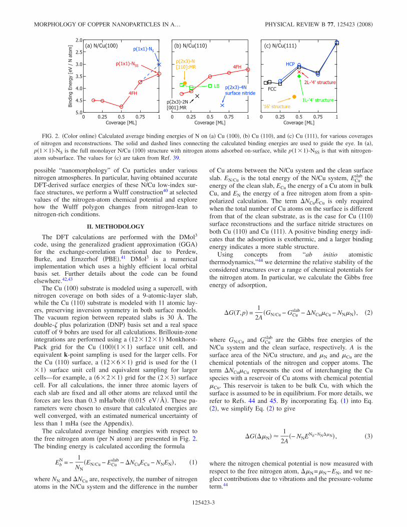
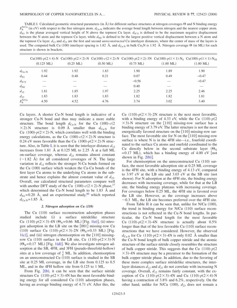
The electronic structure of N adsorbates on Cu is nowpresented. The calculated change in work function ����,with respect to the clean Cu surface, and N-induced surfacedipole moment ��� as a function of coverage for the low-index surfaces are displayed in Fig. 3. The work function isdefined to be the difference between the electrostatic poten-tial in the vacuum and the Fermi energy of the slab. Thesurface dipole moment � �in Debye� is evaluated by theHelmholtz equation
� =A ��
12�, �5�
where A is the area in Å2 per �1�1� surface unit cell, �� isthe work-function change in eV, and � is the coverage inmonolayers.
The surface dipole moment is found to decrease with in-creasing coverage for the Cu �100� and Cu �110� structures.This behavior can be understood by considering the electrontransfer process between adsorbate and substrate atoms:There is a substantial electronegativity difference between Nand Cu �3.04−1.90=1.14�,59 so electrons are transferred �orpart thereof� from the Cu to N atoms. However, with increas-ing coverage, there will be a repulsive interaction betweenthe partially negatively charged N atoms. To counter thisrepulsion, there will be a partial charge transfer of electrondensity back to the substrate, thus decreasing the surfacedipole moment. The surface dipole moment is negative forthe 1-ML Cu �100� subsurface structure, due to the positionof the electronegative N atoms below the Cu surface. Thisresults in a net positive charge at the surface and hence anoutward-pointing, negative dipole moment.
For electronegative adsorbates, �� typically increaseswith coverage, as more effective negative charges are addedto the surface. This is observed in the Cu �100� chemisorp-tion phases, where �� increases from 0.29 eV at 0.125 MLto 1.96 eV for 1 ML coverage of N, positioned above thesurface. The sharp drop in �� for the 1-ML Cu �100� sub-
surface structure is due to the position of N below the sur-face. From Eq. �5�, it is clear that a negative surface dipolemoment results in a negative-work function change. The 0.5-ML-coverage structure Cu �100�-c�2�2�-N has a slightlylower work-function change compared to the 0.25-ML struc-ture on Cu �100�. This may be attributed to screening effects:the N atom in the Cu �100�-c�2�2�-N structure is posi-tioned 0.21 Šabove the surface Cu layer, while N in theCu �100�-p�2�2�-N structure is 0.48 Šabove the surfaceCu layer. Hence, the contributions to �� from the N atomsmay be reduced due a more efficient screening from the Cuatoms in the Cu �100�-c�2�2�-N structure.
Utilizing the simple relation that the surface dipole � isproportional to the product of the averaged vertical distanceof N �i.e., dN1� from the substrate and the effective electroniccharge on N, QN, we can estimate the surface dipolemoment.47 QN is estimated from the Mulliken populationpartition method. This form of charge population analysis,although not an absolute measure of the exact charge distri-bution, does provide a consistent measure of relative elec-tronic charge �re�distribution. The average height of the Natom with respect to the top Cu layer, dN1, for theCu �100�-c�2�2�-N and Cu �100�-p�2�2�-N structures is0.21 and 0.48 Å, respectively. Their corresponding QN val-ues are 0.74e and 0.65e. Thus, for Cu �100�-c�2�2�-N, theproduct is dN1QN=0.16e Å and that for Cu �100�-p�2�2�-N is 0.31e Å. From this simple analysis, one can then
� � �
� � �
� � �
� � �
� � �
� � � �
��� �
������
��������
�����
� � �
� � �
� � �
� � �
� � �
� � � �
� � � ����
� ����!"��#���$�
�� � % �� � �� � � ��! � & � � # � � � ' �
� � � � � � �
� � � � � � � � � � � �
� � � � � � �
� � � � � � � � � � � � � � � � �
� � � � � � �
� � � � � � � � � � � �
� � � � � � �
� � � � � � � � � � � � � � � � �
( � )
( � )
FIG. 3. �Color online� Calculated �a� surface dipole moment ���and �b� work-function change ���� relative to the clean Cu surfaceas a function of coverage for N adsorption at the 4FH site on the Cu�100� �shown as open-circle data points� and Cu �110� �shown asopen-square data points� surfaces. The diamond-shaped data pointslabeled as “Cu �110� �recon.�” represent the following structures:Cu �110�-p�2�3�-N at 0.17 ML, Cu �110�-p�2�3�-2N at 0.33ML, and Cu �110�-p�2�3�-4N at 0.66 ML. Cu �100�-p�1�1�-NS is the full monolayer N/Cu �100� structure with nitrogenatoms adsorbed on the surface in the 4FH site.
MORPHOLOGY OF COPPER NANOPARTICLES IN A… PHYSICAL REVIEW B 77, 125423 �2008�
125423-7
easily see why Cu �100�-c�2�2�-N has a lower work-function change compared to Cu �100�-p�2�2�-N.
The trend in work-function change for N chemisorption inthe 4FH site of the unreconstructed Cu �110� surface in-creases with coverage, similar to the chemisorption phase onCu �100�. For the reconstruction phases, the Cu �110�-p�2�3�-2N and Cu �110�-p�2�3�-4N structures, correspond-ing to coverages of 0.33 ML and 0.66 ML, respectively, havealmost identical work functions.
The �� trend for the reconstructed N/Cu �110� structurescan be understood again by calculating the estimated surfacedipole moment using the effective electronic charges on N inthese two structures and the average height of the N atomwith respect to the top Cu layer, dN1: for the Cu �110�-p�2�3�-2N structure, dN1=0.11 Å, and for Cu �110�-p�2�3�-4N, dN1=0.13 Å, i.e., they are comparable. However,the Cu �110�-p�2�3�-4N structure experiences greaterscreening effects due to the higher coordination of N atomsin this structure: N is bonded to four surface Cu atoms in theCu �110�-p�2�3�-4N structure, while N is bonded to twosurface Cu atoms in the Cu �110�-p�2�2�-2N structure.The resulting values of QN are 0.73e and 0.67e, respectively.This results in Cu �110�-p�2�3�-2N having a value ofdN1QN=0.07e Å and Cu �110�-p�2�3�-4N a value of0.09e Å, and this correlates well with the actual DFT-calculated surface dipole moments.
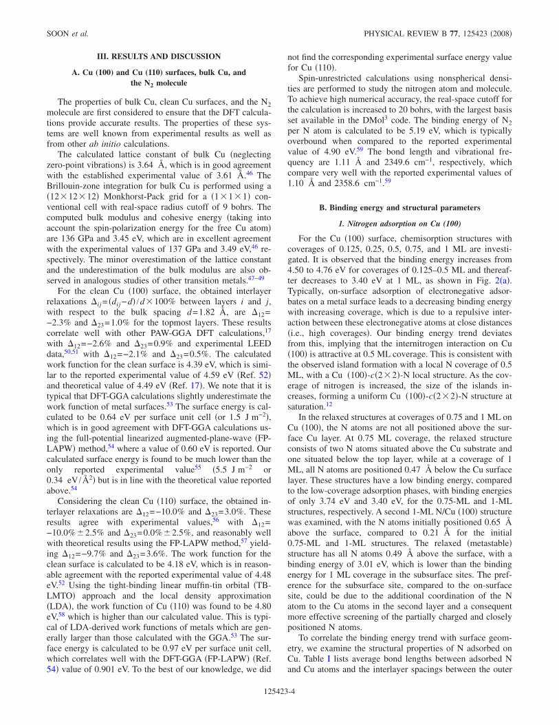
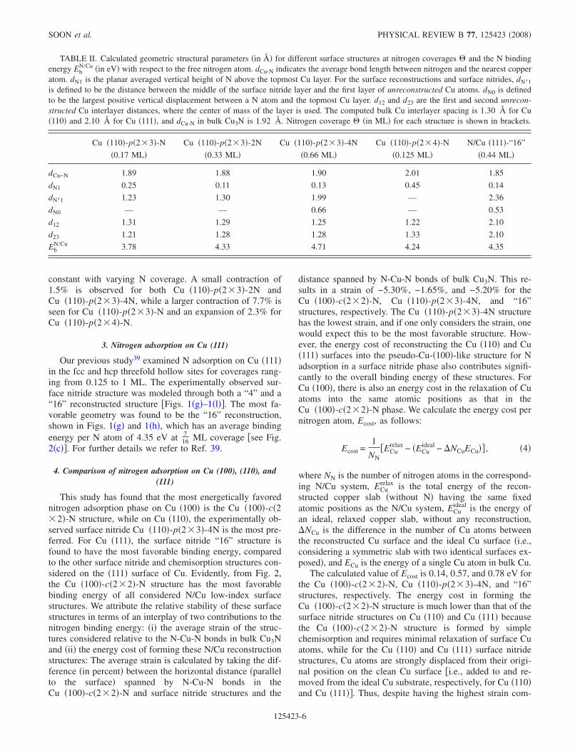
The difference electron density distributions for selectedN/Cu �100� and surface nitride phases, in planes perpendicu-lar to the surface along the N-Cu bond, are presented in Fig.4. These quantities are calculated as
n��r� = nN/Cu�r� − nCu�r� − nN�r� . �6�
Here nN/Cu is the total electron density of the substrate/adsorbate system, from which the electron density of boththe clean surface, nCu, and that of the corresponding isolatednitrogen adlayer, nN, are subtracted. The positions of the pureCu surface and nitrogen atoms are taken to be the ones of therelaxed adsorbate system and are kept fixed.
For the selected N/Cu surface structures shown in Fig. 4,we note some similarities: The nitrogen atoms appear to bealmost coplanar with the adjacent Cu atoms. The electron
densities of the nearest-neighbor Cu atoms are depleted �de-picted as dotted lines in Fig. 4�, while the electron densitiesof N atoms are enhanced �depicted as solid lines in Fig. 4�.This can be attributed to the large electronegativity of N. Theaccumulation of electron density on the vacuum side of thesurface for N results in an inward pointing surface dipolemoment and a positive ��. The impact of the N atoms on itsneighboring Cu atoms can also be seen to extend to the sec-ond Cu substrate layer. In particular, for the surface nitridereconstructions, there are N atoms which affect Cu atoms inthe reconstructed layer as well as in the first layer of theunreconstructed slab.
To illustrate the difference in surface dipole moment ob-served for subsurface N/Cu �100� adsorption phase �at 1 ML�Cu �100�-p�1�1�-NSS and the corresponding on-surface ad-sorption phase Cu �100�-p�1�1�-NS, their respective differ-ence electron density distributions are shown in Figs. 4�a�and 4�b�. The electron density for Cu �100�-p�1�1�-NS re-sembles that of the Cu �100�-c�2�2�-N structure. However,for Cu �100�-p�1�1�-NSS, it is clear that the electron den-sity enhancement of the N atoms is concentrated below theCu surface, thus leading to the outward-pointing surface di-pole moment and negative ��. Furthermore, from the de-pleted electron density of the neighboring surface andsecond-layer Cu atoms, it is clear that N in this structure notonly interacts and bonds to Cu atoms on the surface, but alsowith Cu atoms below the surface.
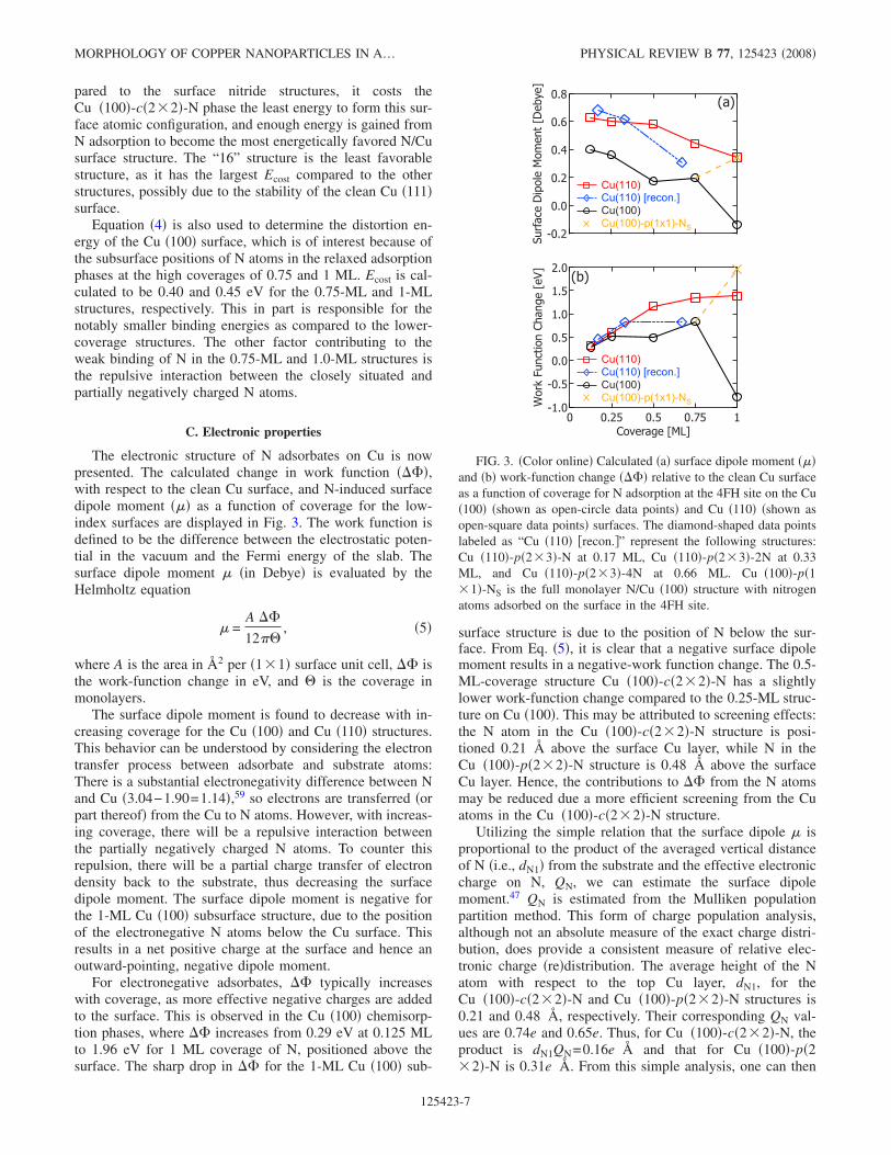
The projected densities-of-states �PDOS� are presented inFigs. 5 and 6. In Fig. 5, for the 0.5 ML Cu �100�-c�2�2�-N structure, single particle wave functions are also plot-ted at the point for various different energy eigenvalues. Inall cases, we observe a renormalization of the N 2p energylevels to lower energies and a hybridization between N 2pand Cu 3d states in the region from −8 to −4 eV. The PDOSfor the Cu �100�-c�2�2�-N structure in Fig. 5 bears someresemblance to the PDOS corresponding to bulk Cu3N �seeFig. 9�a� in Ref. 39�; however, there is a noticeable peak ataround −4 eV, which is absent from the PDOS correspond-ing to the bulk structure. Plotting the spatial distribution ofthe single-particle wave function at this eigenstate shows thatthis peak is due to weak N-Cu and strong Cu-Cu bonding
FIG. 4. Difference charge densities of �a�Cu �100�-c�2�2�-N, �b� Cu �100�-p�1�1�-NS,�c� Cu �100�-p�1�1�-NSS, �d� Cu �110�-p�2�3�-4N, and �e� N/Cu �111�:”16” structure. Allplots are viewed along the N-Cu-N bond. Thedashed lines represent regions of charge deple-tion, and the solid lines depict regions of chargeaccumulation. The lowest positive contour linecorresponds to 0.001 electron bohr−3, while thehighest negative contour line corresponds to avalue of −0.001 electron bohr−3. In between, theelectron density changes successively by a factorof 101/3 electron bohr−3.
SOON et al. PHYSICAL REVIEW B 77, 125423 �2008�
125423-8
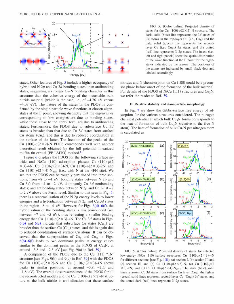
states. Other features of Fig. 5 include a higher occupancy ofhybridized N 2p and Cu 3d bonding states, than antibondingstates, suggesting a stronger Cu-N bonding character in thisstructure than the cohesive energy of the metastable bulknitride material �which is the case, i.e., of −4.76 eV versus−4.03 eV�. The nature of the states in the PDOS is con-firmed by the single-particle wave functions at chosen eigen-states at the point, showing distinctly that the eigenvaluescorresponding to low energies are due to bonding states,while those close to the Fermi level are due to antibondingstates. Furthermore, the PDOS due to subsurface Cu 3dstates is broader than that due to Cu 3d states from surfaceCu atoms �Cus�, and this is due to reduced coordination atthe surface of the latter. The location of the peaks of theCu �100�-c�2�2�-N PDOS corresponds well with anothertheoretical result obtained by the full potential linearizedmuffin-tin orbital �FP-LMTO� method.61
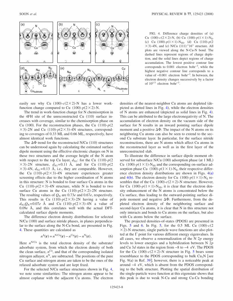
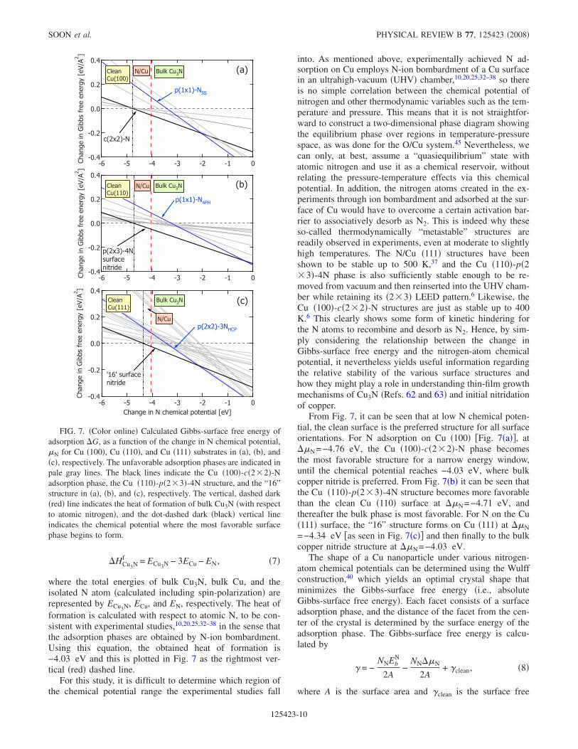
Figure 6 displays the PDOS for the following surface ni-tride and N/Cu �110� adsorption phases: Cu �110�-p�2�3�-4N, Cu �110�-p�2�3�-N, Cu �110�-p�2�3�-2N, andCu �110�-p�2�4�-N4FH �i.e., with N at the 4FH site�. Wesee that the PDOS can be roughly partitioned into three sec-tions: from −8 to −4 eV, bonding states between N 2p andCu 3d; from −4 to −2 eV, dominantly Cu 3d nonbondingstates; and antibonding states between N 2p and Cu 3d at −2to 2 eV above the Fermi level. Similar to that seen in Fig. 5,there is a renormalization of the N 2p energy levels to lowerenergies and a hybridization between N 2p and Cu 3d statesin the region −8 to −4 eV. However, for Figs. 6�d�–6�f�, thehybridization of the bonding states is less pronounced �seebetween −7 and −5 eV�, thus reflecting a smaller bindingenergy than Cu �110�-p�2�3�-4N. The Cu 3d states in Figs.6�b� and 6�c� indicate that subsurface Cu states �Cuss� arebroader than the surface Cu �Cus� states, and this is again dueto reduced coordination of surface Cu atoms. It can be ob-served that the superposition of Cus and Cuss in Figs.6�b�–6�f� leads to two dominant peaks, at energy valuessimilar to the dominant peaks in the PDOS of Cu3N, ataround −3.8 and −2.5 eV �see Fig. 9�a� in Ref. 39�.
A comparison of the PDOS due to the Cu �111� “16”structure �see Figs. 9�b� and 9�c� in Ref. 39� with the PDOSfor Cu �100�-c�2�2�-N and Cu �110�-p�2�3�-4N showspeaks in similar positions �at around −3.8, −2.5, and−1.8 eV�. The overall close resemblance of the PDOS for allthe reconstructed models and the Cu �100�-c�2�2�-N struc-ture to the bulk nitride is an indication that these surface
nitrides and N chemisorption on Cu �100� could be a precur-sor phase before onset of the formation of the bulk material.For details of the PDOS of N/Cu �111� structures and Cu3N,we refer the reader to Ref. 39.
D. Relative stability and nanoparticle morphology
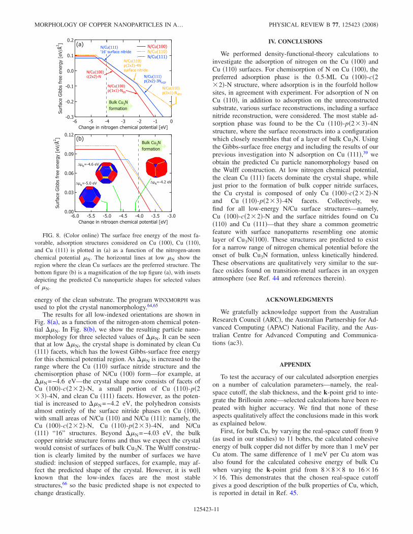
In Fig. 7 we show the Gibbs-surface free energy of ad-sorption for the various structures considered. The nitrogenchemical potential at which bulk Cu3N forms corresponds tothe heat of formation of bulk Cu3N �relative to the free Natom�. The heat of formation of bulk Cu3N per nitrogen atomis calculated as
� �
� �
� �
�
�
������ �
��� ��
� � � � � � � � � �
� � � � � � � � �
� �
� �
� �
�
������� �
��� ��
� � � � � � � � � �� �
� �
� �
�
�
������ �
��� ��
� � � � � � � � � �� �
� �
� �
�
�
������ �
��� ��
� � � � � � � � � �
� � � � � � � � �
� �
� �
� �
�
�
������ �
��� ��
� � � � � � � � � �� �
� �
� �
�
�
������ �
��� ��
� � � � � � � � � �
� ��� �
� �� �
� �
� � �
� �� �
� �
� ��� �
��� �
� �� �
� �
� �� �
� �
� ��� �
� ��� �
� ��� �
��� �
�� �
� �
�
� �
� �
� �
� � �
� �
� � �
� ��� �
� �� �
� �
� � � � � � � � � � � � � � � � �
� � � � � � � � � � � � � � � � � �
� � � � � � � � � � � � � � � � � � �
� � � � � � �
� � � � � � � �
� � � � � � � � � �
FIG. 6. �Color online� Projected density of states for selectedlow-energy N/Cu �110� surface structures: Cu �110�-p�2�3�-4Nfor different sections �see Fig. 1�f��: �a� section I, �b� section II, and�c� section III and �d� Cu �110�-p�2�3�-N, �e� Cu �110�-p�2�3�-2N, and �f� Cu �110�-p�2�4�-N4FH. The dark �blue� solidlines represent Cu 3d states from surface Cu layer �CuS�, the lighter�green� solid lines represent second-layer Cu �CuSS� 3d states, andthe dotted dark �red� lines represent N 2p states.
� �
� �
� �
�
�
������ �
��� ��
� � � � � � � � � �
� � � � � � � � �
� �� �
� ��
�
� � �
� ��� �
� �� �� �
�
FIG. 5. �Color online� Projected density ofstates for the Cu �100�-c�2�2�-N structure. Thedark, solid �blue� line represents the 3d states ofCu atoms in the top-layer Cu �i.e., CuS� and thepale, solid �green� line represents the second-layer Cu �i.e., CuSS� 3d states, and the dotted�red� line represents N 2p states. The insets �i.e.,left and right panels� show the spatial distributionof the wave function at the point for the eigen-states indicated by the arrows. The positions ofthe atoms are indicated by small black dots andlabeled accordingly.
MORPHOLOGY OF COPPER NANOPARTICLES IN A… PHYSICAL REVIEW B 77, 125423 �2008�
125423-9
�HCu3Nf = ECu3N − 3ECu − EN, �7�
where the total energies of bulk Cu3N, bulk Cu, and theisolated N atom �calculated including spin-polarization� arerepresented by ECu3N, ECu, and EN, respectively. The heat offormation is calculated with respect to atomic N, to be con-sistent with experimental studies,10,20,25,32–38 in the sense thatthe adsorption phases are obtained by N-ion bombardment.Using this equation, the obtained heat of formation is−4.03 eV and this is plotted in Fig. 7 as the rightmost ver-tical �red� dashed line.
For this study, it is difficult to determine which region ofthe chemical potential range the experimental studies fall
into. As mentioned above, experimentally achieved N ad-sorption on Cu employs N-ion bombardment of a Cu surfacein an ultrahigh-vacuum �UHV� chamber,10,20,25,32–38 so thereis no simple correlation between the chemical potential ofnitrogen and other thermodynamic variables such as the tem-perature and pressure. This means that it is not straightfor-ward to construct a two-dimensional phase diagram showingthe equilibrium phase over regions in temperature-pressurespace, as was done for the O/Cu system.45 Nevertheless, wecan only, at best, assume a “quasiequilibrium” state withatomic nitrogen and use it as a chemical reservoir, withoutrelating the pressure-temperature effects via this chemicalpotential. In addition, the nitrogen atoms created in the ex-periments through ion bombardment and adsorbed at the sur-face of Cu would have to overcome a certain activation bar-rier to associatively desorb as N2. This is indeed why theseso-called thermodynamically “metastable” structures arereadily observed in experiments, even at moderate to slightlyhigh temperatures. The N/Cu �111� structures have beenshown to be stable up to 500 K,37 and the Cu �110�-p�2�3�-4N phase is also sufficiently stable enough to be re-moved from vacuum and then reinserted into the UHV cham-ber while retaining its �2�3� LEED pattern.6 Likewise, theCu �100�-c�2�2�-N structures are just as stable up to 400K.6 This clearly shows some form of kinetic hindering forthe N atoms to recombine and desorb as N2. Hence, by sim-ply considering the relationship between the change inGibbs-surface free energy and the nitrogen-atom chemicalpotential, it nevertheless yields useful information regardingthe relative stability of the various surface structures andhow they might play a role in understanding thin-film growthmechanisms of Cu3N �Refs. 62 and 63� and initial nitridationof copper.
From Fig. 7, it can be seen that at low N chemical poten-tial, the clean surface is the preferred structure for all surfaceorientations. For N adsorption on Cu �100� �Fig. 7�a��, at��N=−4.76 eV, the Cu �100�-c�2�2�-N phase becomesthe most favorable structure for a narrow energy window,until the chemical potential reaches −4.03 eV, where bulkcopper nitride is preferred. From Fig. 7�b� it can be seen thatthe Cu �110�-p�2�3�-4N structure becomes more favorablethan the clean Cu �110� surface at ��N=−4.71 eV, andthereafter the bulk phase is most favorable. For N on the Cu�111� surface, the “16” structure forms on Cu �111� at ��N=−4.34 eV �as seen in Fig. 7�c�� and then finally to the bulkcopper nitride structure at ��N=−4.03 eV.
The shape of a Cu nanoparticle under various nitrogen-atom chemical potentials can be determined using the Wulffconstruction,40 which yields an optimal crystal shape thatminimizes the Gibbs-surface free energy �i.e., absoluteGibbs-surface free energy�. Each facet consists of a surfaceadsorption phase, and the distance of the facet from the cen-ter of the crystal is determined by the surface energy of theadsorption phase. The Gibbs-surface free energy is calcu-lated by
� = −NNEb
N
2A−
NN��N
2A+ �clean, �8�
where A is the surface area and �clean is the surface free
� � � �
� � � �
� � �
� � �
� � �
�����
�����������������
��
� � � � � � � � � � � � �
� � � � � � � � � � �
� � ! � � � "
� � � �
� � � �
� � �
� � �
� � �
�����
�����������������
��
� � � � � � � � � � � � �
� � � �
� � � �
� � �
� � �
� � �
�����
�����������������
��
� � � � � � � � � � � � �
� � � � � " # � � $ � # � � % & ' � ' � � � � � � �
� � �" � � �
� � � � � � � � � � �
� � ! � � � " � � �" � � �
� � � � � � � � � � �
� � ! � � � " � # �
" � � �
# � � ( � � � "
% � � ( � � � ") )
% � � ( � � � � "� � � � � # � � ' � � * �
% � � ( � � � " � + ,
- � � - � � � � � # � � ' � � * �
% � � ( � � � � " , � .
FIG. 7. �Color online� Calculated Gibbs-surface free energy ofadsorption �G, as a function of the change in N chemical potential,�N for Cu �100�, Cu �110�, and Cu �111� substrates in �a�, �b�, and�c�, respectively. The unfavorable adsorption phases are indicated inpale gray lines. The black lines indicate the Cu �100�-c�2�2�-Nadsorption phase, the Cu �110�-p�2�3�-4N structure, and the “16”structure in �a�, �b�, and �c�, respectively. The vertical, dashed dark�red� line indicates the heat of formation of bulk Cu3N �with respectto atomic nitrogen�, and the dot-dashed dark �black� vertical lineindicates the chemical potential where the most favorable surfacephase begins to form.
SOON et al. PHYSICAL REVIEW B 77, 125423 �2008�
125423-10
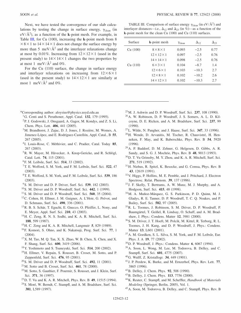
energy of the clean substrate. The program WINXMORPH wasused to plot the crystal nanomorphology.64,65
The results for all low-indexed orientations are shown inFig. 8�a�, as a function of the nitrogen-atom chemical poten-tial ��N. In Fig. 8�b�, we show the resulting particle nano-morphology for three selected values of ��N. It can be seenthat at low ��N, the crystal shape is dominated by clean Cu�111� facets, which has the lowest Gibbs-surface free energyfor this chemical potential region. As ��N is increased to therange where the Cu �110� surface nitride structure and thechemisorption phase of N/Cu �100� form—for example, at��N=−4.6 eV—the crystal shape now consists of facets ofCu �100�-c�2�2�-N, a small portion of Cu �110�-p�2�3�-4N, and clean Cu �111� facets. However, as the poten-tial is increased to ��N=−4.2 eV, the polyhedron consistsalmost entirely of the surface nitride phases on Cu �100�,with small areas of N/Cu �110� and N/Cu �111�: namely, theCu �100�-c�2�2�-N, Cu �110�-p�2�3�-4N, and N/Cu�111� “16” structures. Beyond ��N=−4.03 eV, the bulkcopper nitride structure forms and thus we expect the crystalwould consist of surfaces of bulk Cu3N. The Wulff construc-tion is clearly limited by the number of surfaces we havestudied: inclusion of stepped surfaces, for example, may af-fect the predicted shape of the crystal. However, it is wellknown that the low-index faces are the most stablestructures,66 so the basic predicted shape is not expected tochange drastically.
IV. CONCLUSIONS
We performed density-functional-theory calculations toinvestigate the adsorption of nitrogen on the Cu �100� andCu �110� surfaces. For chemisorption of N on Cu �100�, thepreferred adsorption phase is the 0.5-ML Cu �100�-c�2�2�-N structure, where adsorption is in the fourfold hollowsites, in agreement with experiment. For adsorption of N onCu �110�, in addition to adsorption on the unreconstructedsubstrate, various surface reconstructions, including a surfacenitride reconstruction, were considered. The most stable ad-sorption phase was found to be the Cu �110�-p�2�3�-4Nstructure, where the surface reconstructs into a configurationwhich closely resembles that of a layer of bulk Cu3N. Usingthe Gibbs-surface free energy and including the results of ourprevious investigation into N adsorption on Cu �111�,39 weobtain the predicted Cu particle nanomorphology based onthe Wulff construction. At low nitrogen chemical potential,the clean Cu �111� facets dominate the crystal shape, whilejust prior to the formation of bulk copper nitride surfaces,the Cu crystal is composed of only Cu �100�-c�2�2�-Nand Cu �110�-p�2�3�-4N facets. Collectively, wefind for all low-energy N/Cu surface structures—namely,Cu �100�-c�2�2�-N and the surface nitrides found on Cu�110� and Cu �111�—that they share a common geometricfeature with surface nanopatterns resembling one atomiclayer of Cu3N�100�. These structures are predicted to existfor a narrow range of nitrogen chemical potential before theonset of bulk Cu3N formation, unless kinetically hindered.These observations are qualitatively very similar to the sur-face oxides found on transition-metal surfaces in an oxygenatmosphere �see Ref. 44 and references therein�.
ACKNOWLEDGMENTS
We gratefully acknowledge support from the AustralianResearch Council �ARC�, the Australian Partnership for Ad-vanced Computing �APAC� National Facility, and the Aus-tralian Centre for Advanced Computing and Communica-tions �ac3�.
APPENDIX
To test the accuracy of our calculated adsorption energieson a number of calculation parameters—namely, the real-space cutoff, the slab thickness, and the k-point grid to inte-grate the Brillouin zone—selected calculations have been re-peated with higher accuracy. We find that none of theseaspects qualitatively affect the conclusions made in this workas explained below.
First, for bulk Cu, by varying the real-space cutoff from 9�as used in our studies� to 11 bohrs, the calculated cohesiveenergy of bulk copper did not differ by more than 1 meV perCu atom. The same difference of 1 meV per Cu atom wasalso found for the calculated cohesive energy of bulk Cuwhen varying the k-point grid from 8�8�8 to 16�16�16. This demonstrates that the chosen real-space cutoffgives a good description of the bulk properties of Cu, which,is reported in detail in Ref. 45.
� � � �
� � � �
� � � �
� � � �
� � � �
��� ������
���
�����
�����
� �
� � � � � � � � � � � � � � � � � � � � � � � � � � � �� � � � � � � � � � ! � � � � � " � � # $ ! � � � � # � � � �
� � � �
� � � �
� � � �
� � �
� � �
� � �
��� ������
���
�����
�����
� �
� � � � � � � � � � � � �� � � � � � � � � � ! � � � � � " � � # $ ! � � � � # � � � �
% � � & � � � '% � � & � � � '% � � & � � � '
% � � & � � � '( � � ( � � � � � � � ) �
% � � & � � � '$ & � * � ' � � % + � ,
% � � & � � � ' & � * � ' � %
% � � & � � � '$ & � * � ' � % � �
% � � & � � � '$ & � * � ' � � %� � � � � � � ) �
% � � & � � � '$ & � * � ' � % � - +
& � '
& � '
� . % / � � � � � �
� . % / � � � � � �
� . % / � � � � � �
0 # 1 � � %
� ! " � � ! �
0 # 1 � � %
� ! " � � ! �
FIG. 8. �Color online� The surface free energy of the most fa-vorable, adsorption structures considered on Cu �100�, Cu �110�,and Cu �111� is plotted in �a� as a function of the nitrogen-atomchemical potential �N. The horizontal lines at low �N show theregion where the clean Cu surfaces are the preferred structure. Thebottom figure �b� is a magnification of the top figure �a�, with insetsdepicting the predicted Cu nanoparticle shapes for selected valuesof �N.
MORPHOLOGY OF COPPER NANOPARTICLES IN A… PHYSICAL REVIEW B 77, 125423 �2008�
125423-11
Next, we have tested the convergence of our slab calcu-lations by testing the change in surface energy, �clean �ineV /Å2�, as a function of the k-point mesh. For example, inTable III, for Cu �100�, increasing the k-point mesh from 8�8�1 to 14�14�1 does not change the surface energy bymore than 5 meV /Å2 and the interlayer relaxations changeat most by 0.01%. Increasing from 12�12�1 �used in thepresent study� to 14�14�1 changes the two properties byat most 1 meV /Å2 and 0%.
For the Cu �110� surface, the change in surface energyand interlayer relaxations on increasing from 12�6�1�used in the present study� to 14�12�1 are similarly atmost 1 meV /Å2 and 0%.
*Corresponding author: [email protected] G. Centi and S. Perathoner, Appl. Catal. 132, 179 �1995�.2 P. J. Godowski, J. Onsgaard, A. Gagor, M. Kondys, and Z. S. Li,
Chem. Phys. Lett. 406, 441 �2005�.3 M. Brandhorst, J. Zajac, D. J. Jones, J. Rozière, M. Womes, A.
Jimenez-López, and E. Rodríguez-Castellón, Appl. Catal., B 55,267 �2005�.
4 I. Louis-Rose, C. Méthivier, and C. Pradier, Catal. Today 85,267 �2003�.
5 R. W. Mayer, M. Hävecker, A. Knop-Gericke, and R. Schlögl,Catal. Lett. 74, 115 �2001�.
6 F. M. Leibsle, Surf. Sci. 514, 33 �2002�.7 T. E. Wofford, S. M. York, and F. M. Leibsle, Surf. Sci. 522, 47
�2003�.8 T. E. Wofford, S. M. York, and F. M. Leibsle, Surf. Sci. 539, 186
�2003�.9 S. M. Driver and D. P. Driver, Surf. Sci. 539, 182 �2003�.
10 S. M. Driver and D. P. Woodruff, Surf. Sci. 442, 1 �1999�.11 S. M. Driver and D. P. Woodruff, Surf. Sci. 560, 35 �2004�.12 C. Cohen, H. Ellmer, J. M. Guigner, A. L’Hoir, G. Prévot, and
D. Schmaus, Surf. Sci. 490, 336 �2001�.13 R. B. S. Schär, T. Eguchi, E. Gnecco, O. Pfeiffer, L. Nony, and
E. Meyer, Appl. Surf. Sci. 210, 43 �2003�.14 H. C. Zeng, R. N. S. Sodhi, and K. A. R. Mitchell, Surf. Sci.
188, 599 �1987�.15 H. C. Zeng and K. A. R. Mitchell, Langmuir 5, 829 �1989�.16 F. Komori, S. Ohno, and K. Nakatsuji, Prog. Surf. Sci. 77, 1
�2004�.17 X. M. Tao, M. Q. Tan, X. X. Zhao, W. B. Chen, X. Chen, and X.
F. Shang, Surf. Sci. 600, 3419 �2006�.18 Y. Yoshimoto and S. Tsuneyuki, Surf. Sci. 514, 200 �2002�.19 H. Ellmer, V. Repain, S. Rousset, B. Croset, M. Sotto, and P.
Zeppenfeld, Surf. Sci. 476, 95 �2001�.20 S. M. Driver and D. P. Woodruff, Surf. Sci. 492, 11 �2001�.21 M. Sotto and B. Croset, Surf. Sci. 461, 78 �2000�.22 M. Sotto, S. Gauthier, F. Pourmir, S. Rousset, and J. Klein, Surf.
Sci. 371, 36 �1997�.23 D. T. Vu and K. A. R. Mitchell, Phys. Rev. B 49, 11515 �1994�.24 S. Moré, W. Berndt, C. Stampfl, and A. M. Bradshaw, Surf. Sci.
381, L589 �1997�.
25 M. J. Ashwin and D. P. Woodruff, Surf. Sci. 237, 108 �1990�.26 A. W. Robinson, D. P. Woodruff, J. S. Somers, A. L. D. Kil-
coyne, D. E. Ricken, and A. M. Bradshaw, Surf. Sci. 237, 99�1990�.
27 L. Wilde, N. Pangher, and J. Haase, Surf. Sci. 347, 33 �1996�.28 H. Wende, D. Arvanitis, M. Tischer, R. Chauvistré, H. Hen-
neken, F. May, and K. Baberschke, Phys. Rev. B 54, 5920�1996�.
29 A. P. Baddorf, D. M. Zehner, G. Helgesen, D. Gibbs, A. R.Sandy, and S. G. J. Mochrie, Phys. Rev. B 48, 9013 �1993�.
30 D. T. Vu Grimsby, M. Y. Zhou, and K. A. R. Mitchell, Surf. Sci.271, 519 �1992�.
31 H. Niehus, R. Spitzl, K. Besocke, and G. Comsa, Phys. Rev. B43, 12619 �1991�.
32 V. Higgs, P. Hollins, M. E. Pemble, and J. Pritchard, J. ElectronSpectrosc. Relat. Phenom. 39, 137 �1986�.
33 J. F. Skelly, T. Bertrams, A. W. Munz, M. J. Murphy, and A.Hodgson, Surf. Sci. 415, 48 �1998�.
34 M. A. Muñoz-Márquez, G. S. Parkinson, P. D. Quinn, M. J.Gladys, R. E. Tanner, D. P. Woodruff, T. C. Q. Noakes, and P.Bailey, Surf. Sci. 582, 97 �2005�.
35 R. L. Toomes, J. Robinson, S. M. Driver, D. P. Woodruff, P.Baumgärtel, T. Geißel, R. Lindsay, O. Schaff, and A. M. Brad-shaw, J. Phys.: Condens. Matter 12, 3981 �2000�.
36 S. M. Driver, J. T. Hoeft, M. Polcik, M. Kittel, R. Terborg, R. L.Toomes, J. H. Kang, and D. P. Woodruff, J. Phys.: Condens.Matter 13, L601 �2001�.
37 A. M. Goedken, S. L. Silva, S. M. York, and F. M. Leibsle, Eur.Phys. J. A 19, 77 �2002�.
38 D. P. Woodruff, J. Phys.: Condens. Matter 6, 6067 �1994�.39 A. Soon, L. Wong, M. Lee, M. Todorova, B. Delley, and C.
Stampfl, Surf. Sci. 601, 4775 �2007�.40 G. Wulff, Z. Kristallogr. 34, 449 �1901�.41 J. P. Perdew, K. Burke, and M. Ernzerhof, Phys. Rev. Lett. 77,
3865 �1996�.42 B. Delley, J. Chem. Phys. 92, 508 �1990�.43 B. Delley, J. Chem. Phys. 113, 7756 �2000�.44 K. Reuter, C. Stampfl, and M. Scheffler, Handbook of Materials
Modeling �Springer, Berlin, 2005�, Vol. 1.45 A. Soon, M. Todorova, B. Delley, and C. Stampfl, Phys. Rev. B
TABLE III. Comparison of surface energy �clean �in eV /Å2� andinterlayer distances—i.e., �12 and �23 �in %�—as a function of thek-point mesh for the clean Cu �100� and Cu �110� surfaces.
Surface k-point mesh �clean �12 �23
Cu �100� 8�8�1 0.093 −2.5 0.77
12�12�1 0.097 −2.5 0.76
14�14�1 0.098 −2.5 0.76
Cu �110� 6�3�1 0.104 −8.7 1.4
12�6�1 0.103 −10.3 2.7
12�8�1 0.102 −10.2 2.6
14�12�1 0.102 −10.3 2.7
SOON et al. PHYSICAL REVIEW B 77, 125423 �2008�
125423-12
73, 165424 �2006�.46 C. Kittel, Introduction to Solid State Physics �Wiley, New York,
1996�.47 W. X. Li, C. Stampfl, and M. Scheffler, Phys. Rev. B 65, 075407
�2002�.48 M. Todorova, K. Reuter, and M. Scheffler, J. Phys. Chem. B
108, 14477 �2004�.49 M. V. Ganduglia-Pirovano and M. Scheffler, Phys. Rev. B 59,
15533 �1999�.50 R. Mayer, C. S. Zhang, K. G. Lynn, W. E. Frieze, F. Jona, and P.
M. Marcus, Phys. Rev. B 35, 3102 �1987�.51 J. Wan, Y. L. Fan, D. W. Gong, S. G. Shen, and X. Q. Fan,
Modell. Simul. Mater. Sci. Eng. 7, 189 �1999�.52 P. O. Gartland, S. Berge, and B. J. Slagsvold, Phys. Rev. Lett.
28, 738 �1972�.53 J. L. F. Da Silva, C. Stampfl, and M. Scheffler, Surf. Sci. 600,
703 �2006�.54 J. L. F. Da Silva, C. Barreteau, K. Schroeder, and S. Blügel,
Phys. Rev. B 73, 125402 �2006�.
55 H. P. Bonzel and M. Nowicki, Phys. Rev. B 70, 245430 �2004�.56 H. L. Davis and J. R. Noonan, Surf. Sci. 126, 245 �1983�.57 J. L. F. Da Silva, K. Schroeder, and S. Blügel, Phys. Rev. B 69,
245411 �2004�.58 H. L. Skriver and N. M. Rosengaard, Phys. Rev. B 46, 7157
�1992�.59 CRC Handbook of Chemistry and Physics, 87th ed., edited by D.
R. Lide �CRC Press, Boca Raton, 2007�.60 T. Lederer, D. Arvanitis, M. Tischer, G. Comelli, L. Tröger, and
K. Baberschke, Phys. Rev. B 48, 11277 �1993�.61 T. Wiell, J. E. Klepeis, P. Bennich, O. Björneholm, N. Wassdahl,
and A. Nilsson, Phys. Rev. B 58, 1655 �1998�.62 Y. Du, A. L. Ji, L. B. Ma, Y. Q. Wang, and Z. X. Cao, J. Cryst.
Growth 280, 490 �2005�.63 G. H. Yue, P. X. Yan, and J. Wang, J. Cryst. Growth 274, 464
�2005�.64 W. Kaminsky, J. Appl. Crystallogr. 38, 566 �2005�.65 W. Kaminsky, J. Appl. Crystallogr. 40, 382 �2007�.66 L. D. Marks, Rep. Prog. Phys. 57, 603 �1994�.
MORPHOLOGY OF COPPER NANOPARTICLES IN A… PHYSICAL REVIEW B 77, 125423 �2008�
125423-13