Embed Size (px)
Citation preview
WARNING!
Hazard warning:
Incorrect installation or repair of Webasto heating systems may cause a fire or result in the emission of carbon monoxide, which can be fatal. Serious or fatal injuries can be caused as a result.
Specialist company training, technical documentation, specialized tools and equipment are required to install and repair Webasto heating and cooling systems.
NEVER attempt to install or repair Webasto heating or cooling systems if you have not successfully completed the company training and thereby acquired the required technical skills, or if you do not have access to the required technical documentation, tools and equipment needed to carry out correct installation and repairs.
ALWAYS follow all Webasto installation and repair instructions and observe all warnings.
Webasto does not accept any liability for defects and damage that are attributable to installation by untrained staff.
Feel the drive
Toyota HiluxDieselfrom Model Year 2005For left-hand drive vehicles only
Ident. No.: 1310486B_EN Fee Euro 10 © Webasto AG
Water Heater Unit
Thermo Top E Additional Heater
Thermo Top C Additional Heater
Thermo Top P Additional Heater
Installation Instructions
e100 0003
e100 0002
e100 0104
Toyota Hilux
Table of Contents
Validity 2Heater Unit/Installation Kit 3Foreword 3General Instructions 3Special Tools 3Explanatory Notes on Document 4Preliminary Work 5Heater unit installation location 5Electrical Connections 6Fan controller 7Digital Timer and Summer/winter switch option 8Remote option (Telestart) 8Preparing installation location 9Preparing heater unit 10Installing heater unit 11Coolant connection 13Combustion air 16Fuel Connection 17Exhaust system 19Final Work 22Operating Instructions for End Customer 23Template 01: 24Template 02: 25
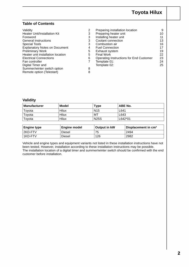
Validity
Vehicle and engine types and equipment variants not listed in these installation instructions have not been tested. However, installation according to these installation instructions may be possible.The installation location of a digital timer and summer/winter switch should be confirmed with the end customer before installation.
Manufacturer Model Type ABE No.Toyota Hilux N15 L641Toyota Hilux MT L643Toyota Hilux N25S L642*01
Engine type Engine model Output in kW Displacement in cm³2KD-FTV Diesel 75 24941KD-FTV Diesel 126 2982
22
Toyota Hilux
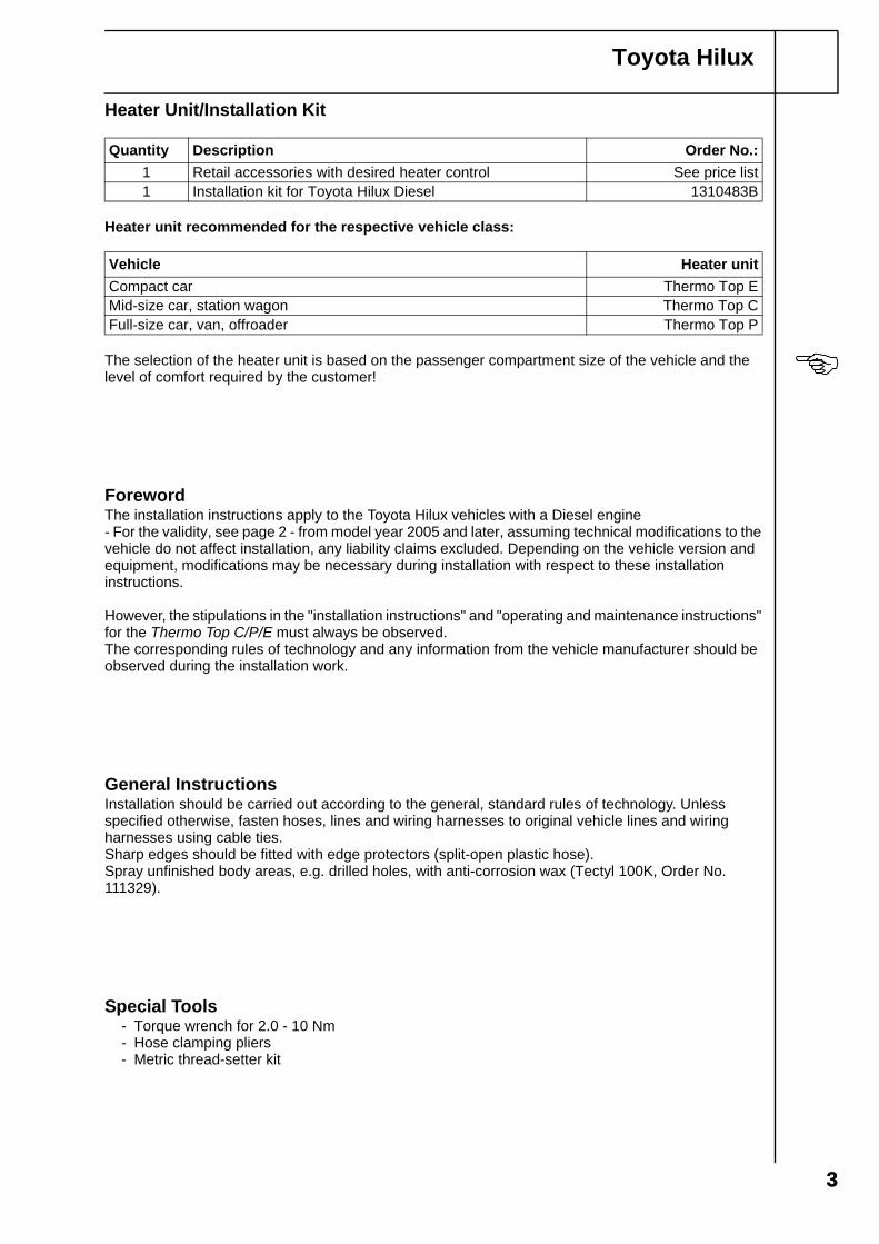
Heater Unit/Installation Kit
Heater unit recommended for the respective vehicle class:
The selection of the heater unit is based on the passenger compartment size of the vehicle and the level of comfort required by the customer!
ForewordThe installation instructions apply to the Toyota Hilux vehicles with a Diesel engine- For the validity, see page 2 - from model year 2005 and later, assuming technical modifications to the vehicle do not affect installation, any liability claims excluded. Depending on the vehicle version and equipment, modifications may be necessary during installation with respect to these installation instructions.
However, the stipulations in the "installation instructions" and "operating and maintenance instructions" for the Thermo Top C/P/E must always be observed.The corresponding rules of technology and any information from the vehicle manufacturer should be observed during the installation work.
General InstructionsInstallation should be carried out according to the general, standard rules of technology. Unless specified otherwise, fasten hoses, lines and wiring harnesses to original vehicle lines and wiring harnesses using cable ties.Sharp edges should be fitted with edge protectors (split-open plastic hose).Spray unfinished body areas, e.g. drilled holes, with anti-corrosion wax (Tectyl 100K, Order No. 111329).
Special Tools- Torque wrench for 2.0 - 10 Nm- Hose clamping pliers- Metric thread-setter kit
Quantity Description Order No.:1 Retail accessories with desired heater control See price list1 Installation kit for Toyota Hilux Diesel 1310483B
Vehicle Heater unitCompact car Thermo Top EMid-size car, station wagon Thermo Top CFull-size car, van, offroader Thermo Top P
33
Toyota Hilux
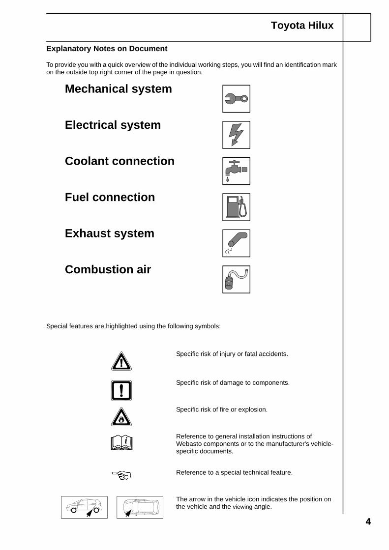
Explanatory Notes on Document
To provide you with a quick overview of the individual working steps, you will find an identification mark on the outside top right corner of the page in question.
44
Special features are highlighted using the following symbols:
Mechanical system
Electrical system
Coolant connection
Fuel connection
Exhaust system
Combustion air
The arrow in the vehicle icon indicates the position on the vehicle and the viewing angle.
Specific risk of injury or fatal accidents.
Specific risk of damage to components.
Specific risk of fire or explosion.
Reference to general installation instructions of Webasto components or to the manufacturer's vehicle-specific documents.
Reference to a special technical feature.
i
Toyota Hilux
Preliminary Work
WARNING!
- Disconnect both batteries.- Depressurize the cooling system.- Copy the factory number from the original type label to the duplicate type label.- Remove years that do not apply from the duplicate label.- Attach the duplicate label (type label) in the appropriate place.- Completely remove the battery on the right.- Remove the coolant reservoir cap on the right.- Open the fuse and relay box.- Open fuel tank cap, ventilate tank- Close the tank cap again.- Remove the lower instrument panel trim on the left.- Remove page 22 "Operating Instructions for End Customer“ and add the operating instructions
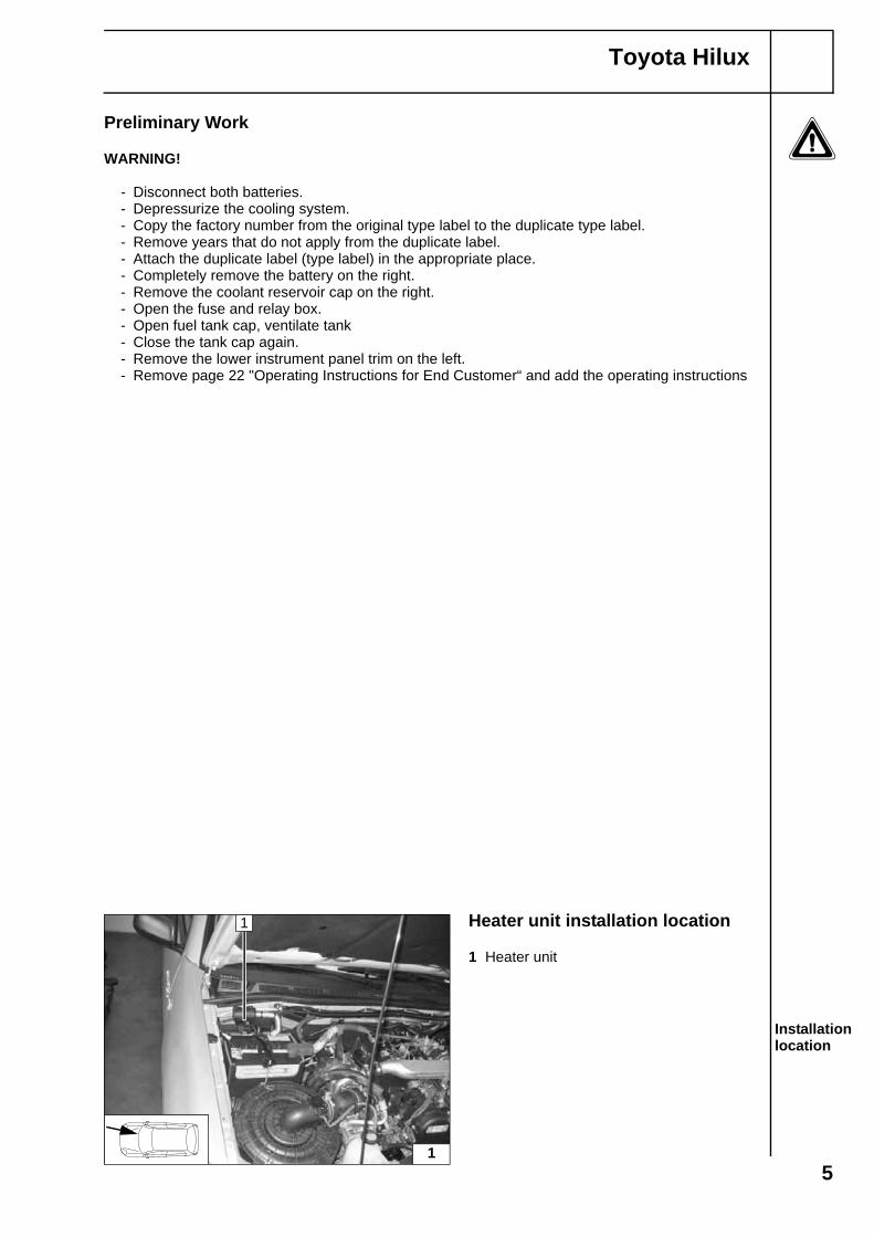
Heater unit installation location
1 Heater unit
Installation location
1
1
5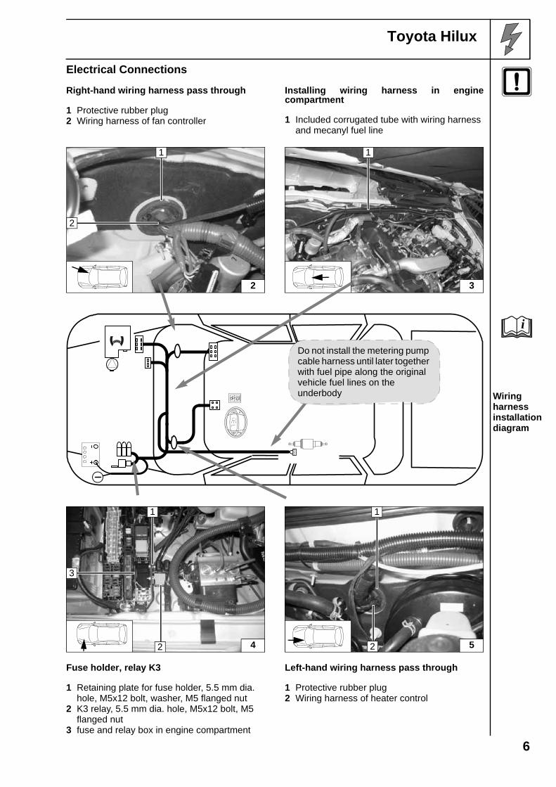
Toyota Hilux
Electrical Connections
Right-hand wiring harness pass through
1 Protective rubber plug2 Wiring harness of fan controller
Installing wiring harness in enginecompartment
1 Included corrugated tube with wiring harness and mecanyl fuel line
Wiring harness installation diagram
Fuse holder, relay K3
1 Retaining plate for fuse holder, 5.5 mm dia. hole, M5x12 bolt, washer, M5 flanged nut
2 K3 relay, 5.5 mm dia. hole, M5x12 bolt, M5 flanged nut
3 fuse and relay box in engine compartment
Left-hand wiring harness pass through
1 Protective rubber plug2 Wiring harness of heater control
2
1
2
3
1
Do not install the metering pump cable harness until later together with fuel pipe along the original vehicle fuel lines on the underbody
i
42
1
3
5
1
2
6
Toyota Hilux
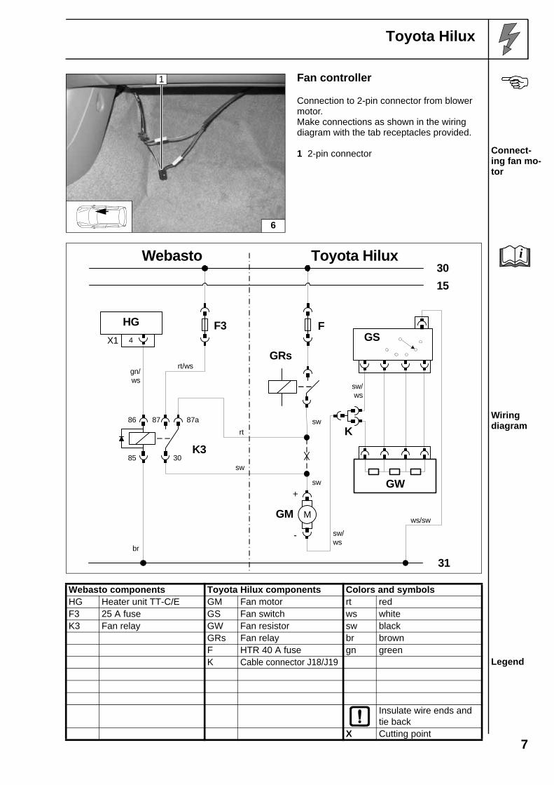
Fan controller
Connection to 2-pin connector from blower motor.Make connections as shown in the wiring diagram with the tab receptacles provided.
1 2-pin connector Connect-ing fan mo-tor
Wiring diagram
Webasto components Toyota Hilux components Colors and symbols
Legend
HG Heater unit TT-C/E GM Fan motor rt redF3 25 A fuse GS Fan switch ws whiteK3 Fan relay GW Fan resistor sw black
GRs Fan relay br brownF HTR 40 A fuse gn greenK Cable connector J18/J19
Insulate wire ends and tie back
X Cutting point
6
1
gn/ws
sw
br
rt/ws
Webasto
31
3015
Toyota Hilux
rt
4
HGX1
F3 F
M
+
-
GM
sw
sw
GRs
K3
87a8786
85 30
sw/ws
GS
GW
sw/ws
ws/sw
K
i
7
Toyota Hilux
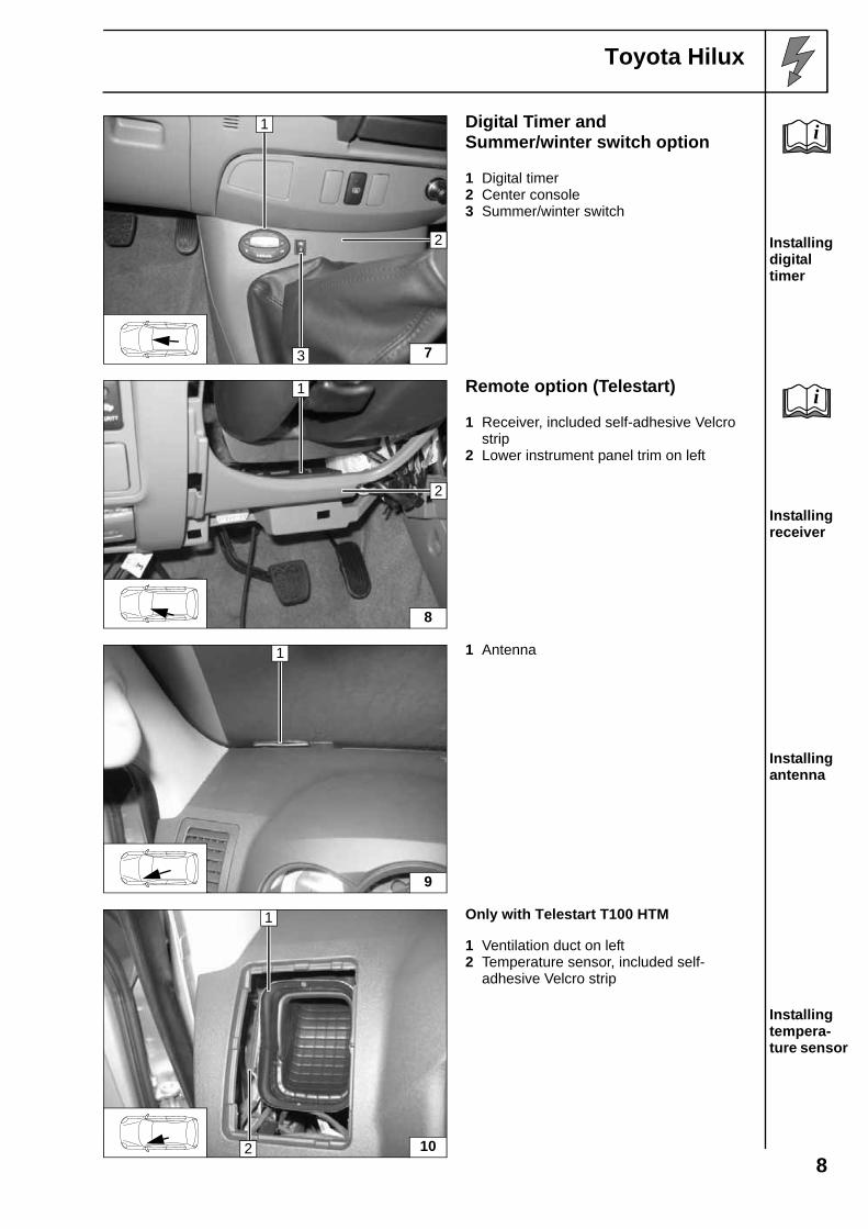
Digital Timer andSummer/winter switch option
1 Digital timer2 Center console3 Summer/winter switch
Installing digital timer
Remote option (Telestart)
1 Receiver, included self-adhesive Velcro strip
2 Lower instrument panel trim on left
Installing receiver
1 Antenna
Installing antenna
Only with Telestart T100 HTM
1 Ventilation duct on left 2 Temperature sensor, included self-
adhesive Velcro strip
Installing tempera-ture sensor
1
3
2
7
i
1
2
8
i
1
9
1
102
8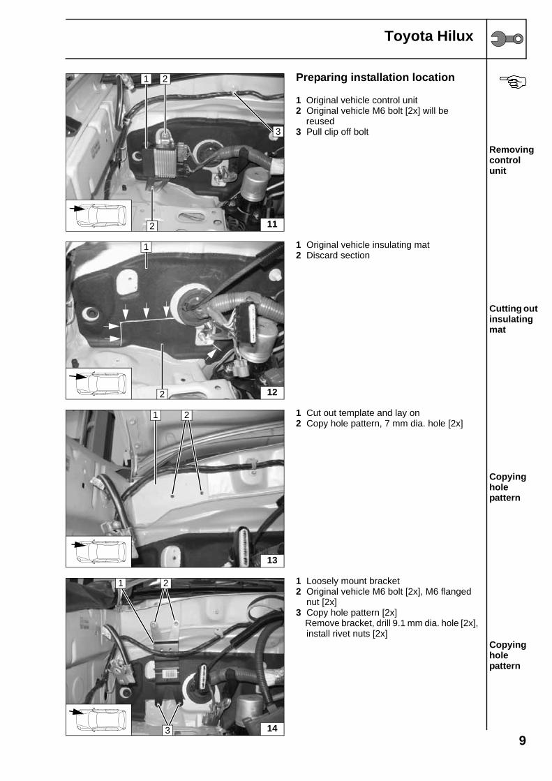
Toyota Hilux
Preparing installation location
1 Original vehicle control unit2 Original vehicle M6 bolt [2x] will be reused3 Pull clip off bolt
Removing control unit
1 Original vehicle insulating mat2 Discard section
Cutting out insulating mat
1 Cut out template and lay on2 Copy hole pattern, 7 mm dia. hole [2x]
Copying hole pattern
1 Loosely mount bracket2 Original vehicle M6 bolt [2x], M6 flanged
nut [2x]3 Copy hole pattern [2x] Remove bracket, drill 9.1 mm dia. hole [2x],
install rivet nuts [2x]Copying hole pattern
11
1 2
2
3
12
1
2
13
1 2
14
1 2
3
9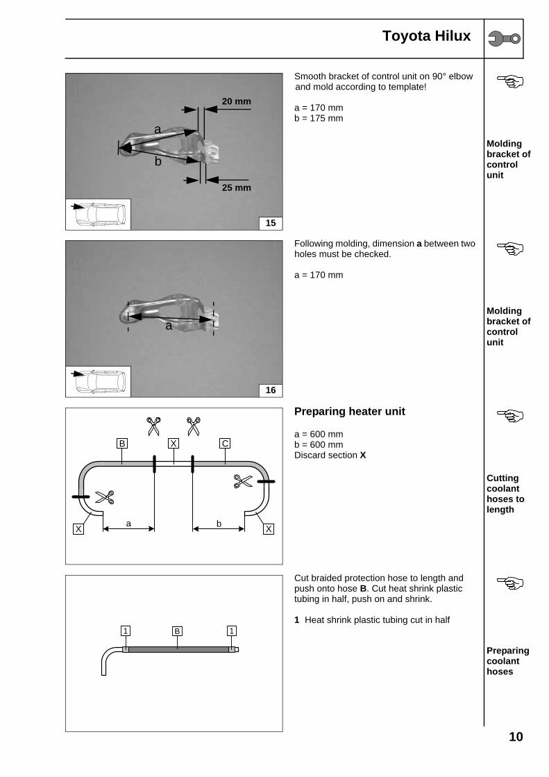
Toyota Hilux
Smooth bracket of control unit on 90° elbow and mold according to template!
a = 170 mmb = 175 mm
Molding bracket of control unit
Following molding, dimension a between two holes must be checked.
a = 170 mm
Molding bracket of control unit
Preparing heater unit
a = 600 mmb = 600 mmDiscard section X
Cutting coolant hoses to length
Cut braided protection hose to length and push onto hose B. Cut heat shrink plastic tubing in half, push on and shrink.
1 Heat shrink plastic tubing cut in half
Preparing coolant hoses
15
20 mm
25 mm
a
b
16
a
a b
B CX
XX
B1 1
10
Toyota Hilux
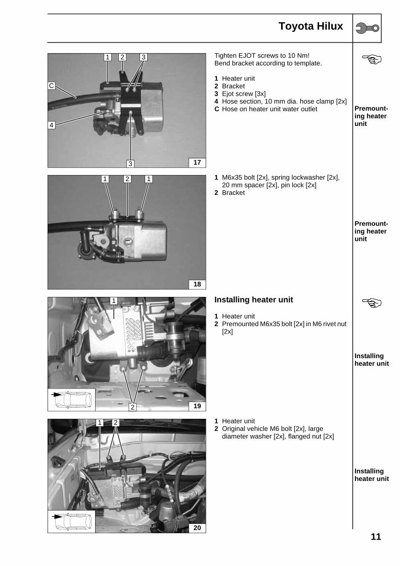
Tighten EJOT screws to 10 Nm!Bend bracket according to template.
1 Heater unit2 Bracket3 Ejot screw [3x]4 Hose section, 10 mm dia. hose clamp [2x]C Hose on heater unit water outlet Premount-
ing heater unit
1 M6x35 bolt [2x], spring lockwasher [2x], 20 mm spacer [2x], pin lock [2x]
2 Bracket
Premount-ing heater unit
Installing heater unit
1 Heater unit2 Premounted M6x35 bolt [2x] in M6 rivet nut
[2x]
Installing heater unit
1 Heater unit2 Original vehicle M6 bolt [2x], large
diameter washer [2x], flanged nut [2x]
Installing heater unit
C
17
1 2
3
3
4
18
1 2 1
19
1
2
20
1 2
11
Toyota Hilux
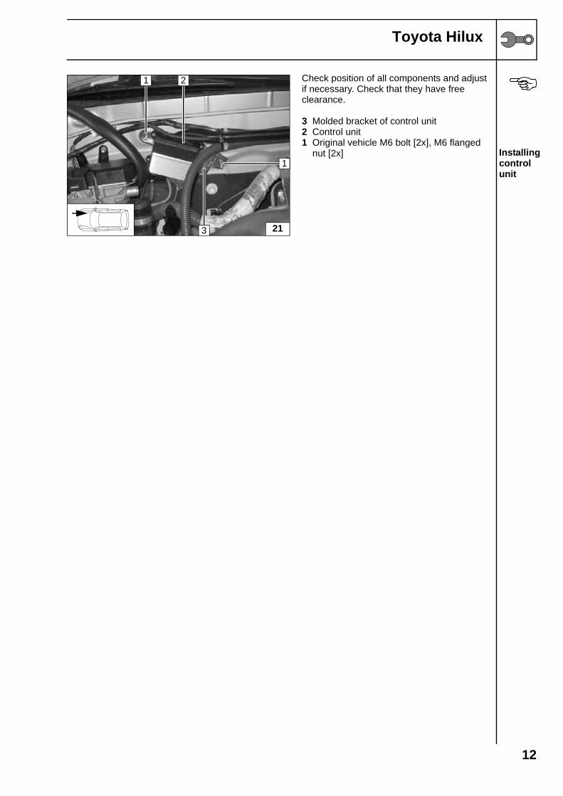
Check position of all components and adjust if necessary. Check that they have free clearance.
3 Molded bracket of control unit2 Control unit1 Original vehicle M6 bolt [2x], M6 flanged
nut [2x] Installing control unit
21
1
1 2
3
12
Toyota Hilux
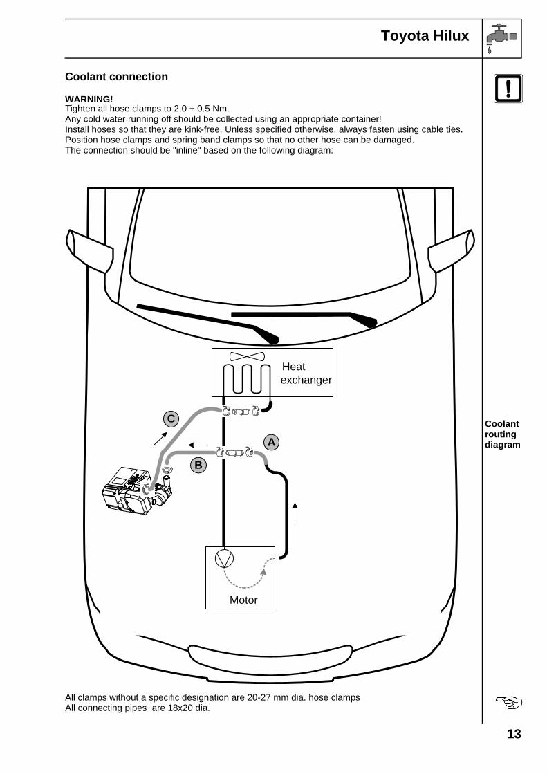
Coolant connection
WARNING!Tighten all hose clamps to 2.0 + 0.5 Nm.Any cold water running off should be collected using an appropriate container!Install hoses so that they are kink-free. Unless specified otherwise, always fasten using cable ties. Position hose clamps and spring band clamps so that no other hose can be damaged.The connection should be "inline" based on the following diagram:
Coolant routing diagram
All clamps without a specific designation are 20-27 mm dia. hose clampsAll connecting pipes are 18x20 dia.
Motor
Heatexchanger
A
B
C
13
Toyota Hilux
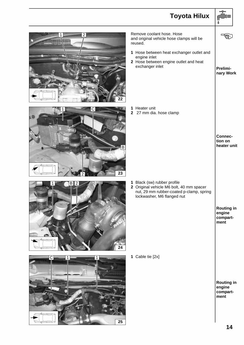
Remove coolant hose. Hoseand original vehicle hose clamps will be reused.
1 Hose between heat exchanger outlet and engine inlet
2 Hose between engine outlet and heat exchanger inlet Prelimi-
nary Work
1 Heater unit2 27 mm dia. hose clamp
Connec-tion on heater unit
1 Black (sw) rubber profile2 Original vehicle M6 bolt, 40 mm spacer
nut, 29 mm rubber-coated p-clamp, spring lockwasher, M6 flanged nut
Routing in engine compart-ment
1 Cable tie [2x]
Routing in engine compart-ment
22
1 2
23
C
B
1
2
24
B1 2
25
C 1 1
14
Toyota Hilux
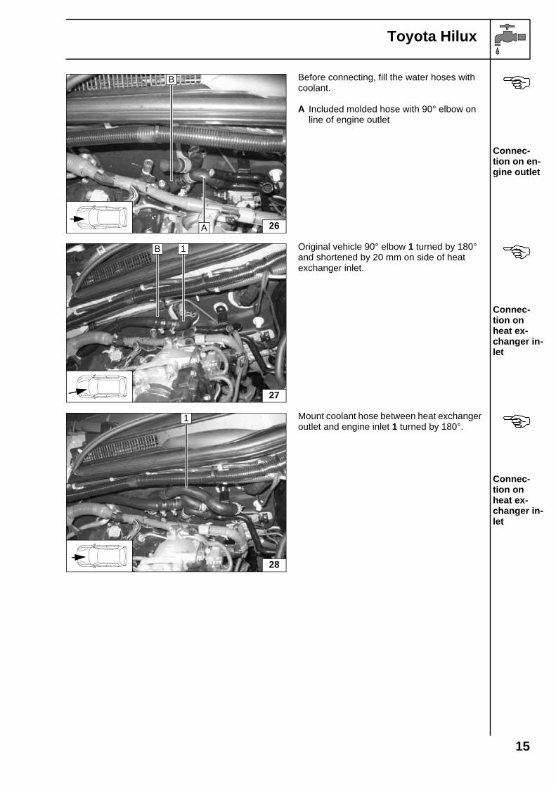
Before connecting, fill the water hoses with coolant.
A Included molded hose with 90° elbow on line of engine outlet
Connec-tion on en-gine outlet
Original vehicle 90° elbow 1 turned by 180°and shortened by 20 mm on side of heatexchanger inlet.
Connec-tion on heat ex-changer in-let
Mount coolant hose between heat exchanger outlet and engine inlet 1 turned by 180°.
Connec-tion on heat ex-changer in-let
26
B
A
27
B 1
28
1
15
Toyota Hilux
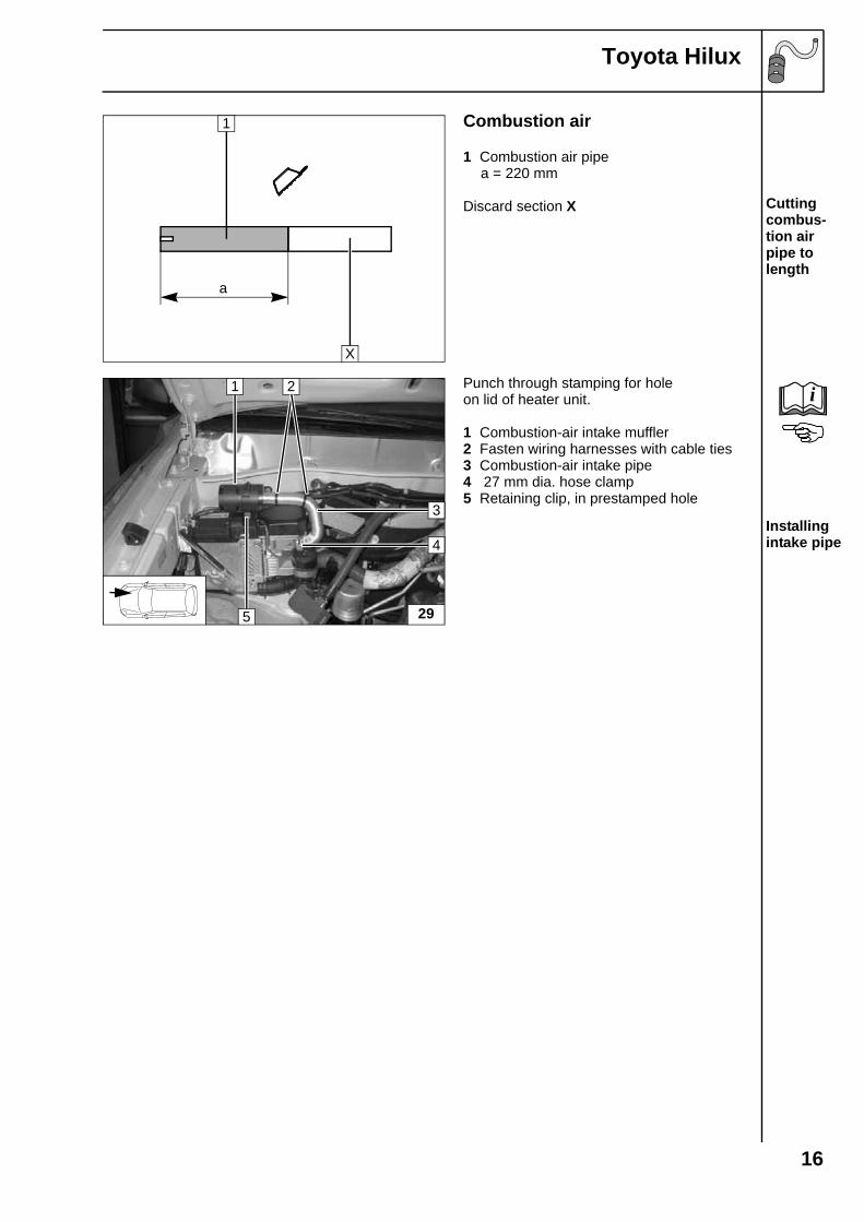
Combustion air
1 Combustion air pipe a = 220 mm
Discard section X Cutting combus-tion air pipe to length
Punch through stamping for holeon lid of heater unit.
1 Combustion-air intake muffler2 Fasten wiring harnesses with cable ties3 Combustion-air intake pipe4 27 mm dia. hose clamp5 Retaining clip, in prestamped hole
Installing intake pipe
a
1
X
29
1 2
5
4
3
i
16
Toyota Hilux
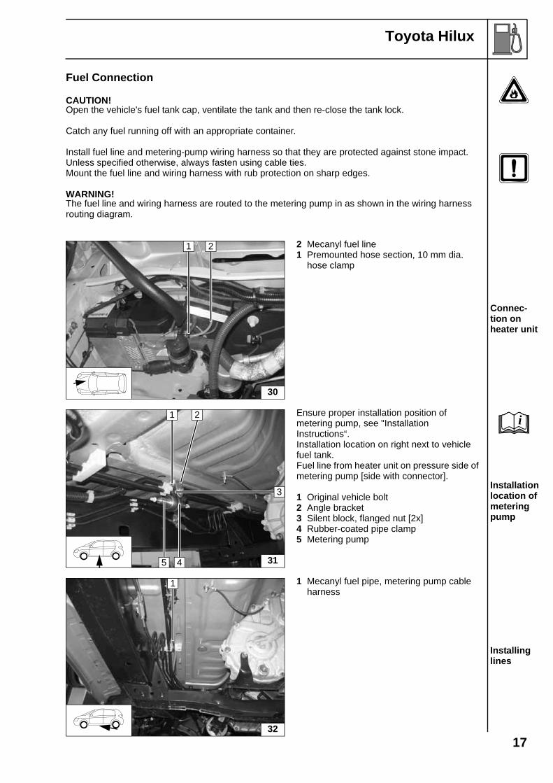
Fuel Connection
CAUTION!Open the vehicle's fuel tank cap, ventilate the tank and then re-close the tank lock.
Catch any fuel running off with an appropriate container.
Install fuel line and metering-pump wiring harness so that they are protected against stone impact. Unless specified otherwise, always fasten using cable ties.Mount the fuel line and wiring harness with rub protection on sharp edges.
WARNING!The fuel line and wiring harness are routed to the metering pump in as shown in the wiring harness routing diagram.
2 Mecanyl fuel line1 Premounted hose section, 10 mm dia.
hose clamp
Connec-tion on heater unit
Ensure proper installation position of metering pump, see "Installation Instructions“.Installation location on right next to vehicle fuel tank.Fuel line from heater unit on pressure side of metering pump [side with connector].
1 Original vehicle bolt2 Angle bracket3 Silent block, flanged nut [2x]4 Rubber-coated pipe clamp5 Metering pump
Installation location of metering pump
1 Mecanyl fuel pipe, metering pump cable harness
Installing lines
30
1 2
31
1 2
5 4
3
i
32
1
17
Toyota Hilux
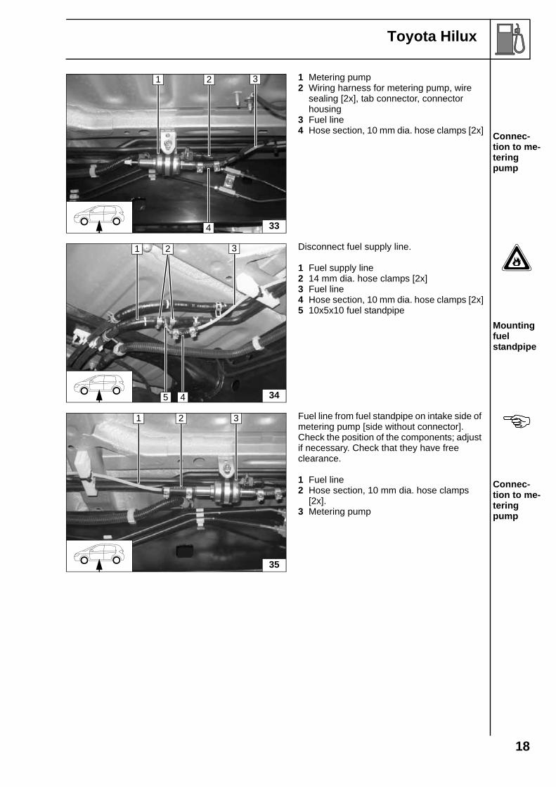
1 Metering pump2 Wiring harness for metering pump, wire
sealing [2x], tab connector, connector housing
3 Fuel line4 Hose section, 10 mm dia. hose clamps [2x] Connec-
tion to me-tering pump
Disconnect fuel supply line.
1 Fuel supply line2 14 mm dia. hose clamps [2x]3 Fuel line4 Hose section, 10 mm dia. hose clamps [2x]5 10x5x10 fuel standpipe
Mounting fuel standpipe
Fuel line from fuel standpipe on intake side of metering pump [side without connector].Check the position of the components; adjust if necessary. Check that they have free clearance.
1 Fuel line2 Hose section, 10 mm dia. hose clamps
[2x].3 Metering pump
Connec-tion to me-tering pump
33
1 2
4
3
34
1 2
45
3
35
1 2 3
18
Toyota Hilux
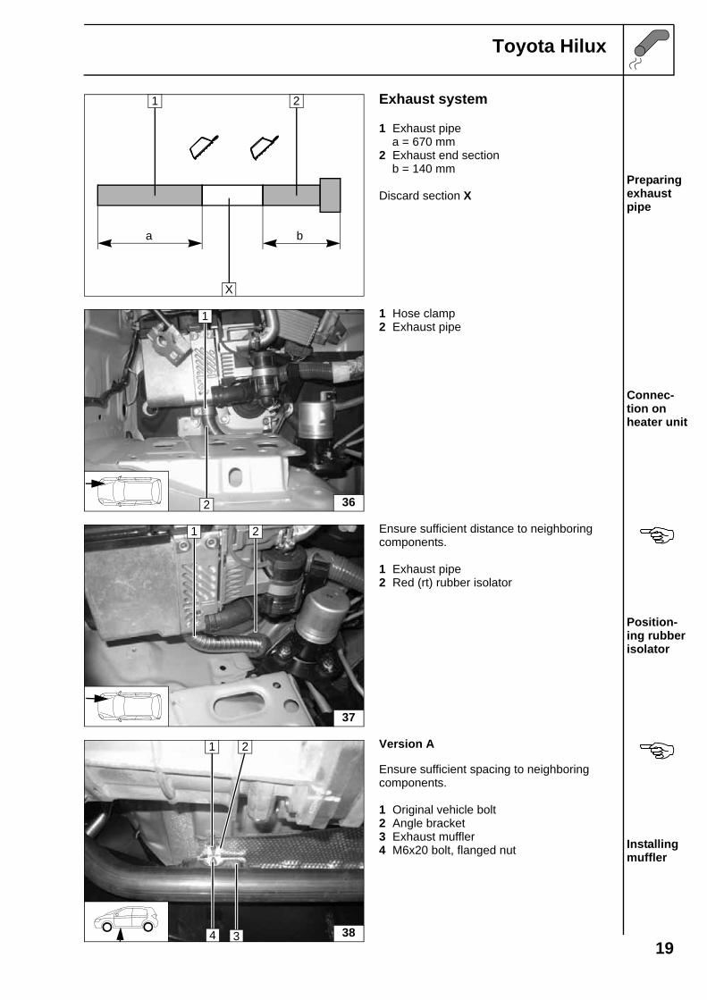
Exhaust system
1 Exhaust pipe a = 670 mm2 Exhaust end section b = 140 mm
Discard section XPreparing exhaust pipe
1 Hose clamp2 Exhaust pipe
Connec-tion on heater unit
Ensure sufficient distance to neighboring components.
1 Exhaust pipe2 Red (rt) rubber isolator
Position-ing rubber isolator
Version A
Ensure sufficient spacing to neighboringcomponents.
1 Original vehicle bolt2 Angle bracket3 Exhaust muffler4 M6x20 bolt, flanged nut Installing
muffler
a b
1 2
X
1
2 36
1 2
37
38
1 2
4 3
19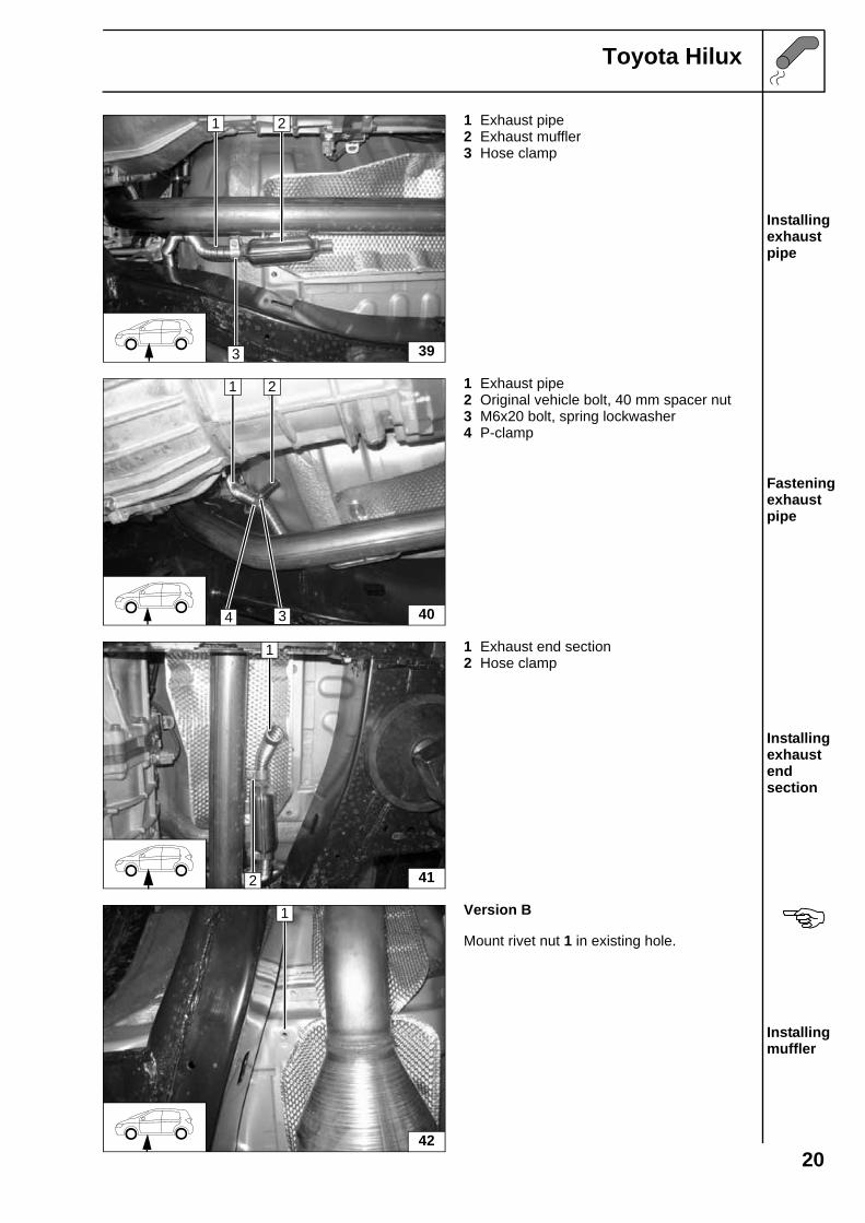
Toyota Hilux
1 Exhaust pipe2 Exhaust muffler3 Hose clamp
Installing exhaust pipe
1 Exhaust pipe2 Original vehicle bolt, 40 mm spacer nut3 M6x20 bolt, spring lockwasher4 P-clamp
Fastening exhaust pipe
1 Exhaust end section2 Hose clamp
Installing exhaust end section
Version B
Mount rivet nut 1 in existing hole.
Installing muffler
1 2
3 39
1 2
4 3 40
1
2 41
42
1
20
Toyota Hilux
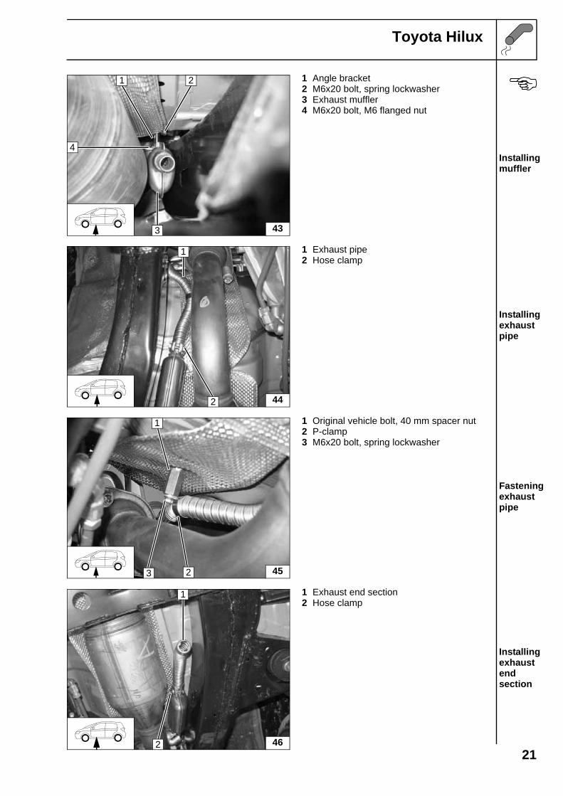
1 Angle bracket2 M6x20 bolt, spring lockwasher3 Exhaust muffler4 M6x20 bolt, M6 flanged nut
Installing muffler
1 Exhaust pipe2 Hose clamp
Installing exhaust pipe
1 Original vehicle bolt, 40 mm spacer nut2 P-clamp3 M6x20 bolt, spring lockwasher
Fastening exhaust pipe
1 Exhaust end section2 Hose clamp
Installing exhaust end section
43
21
4
3
1
2 44
1
3 2 45
1
2 46
21
Toyota Hilux
Final Work
WARNING!Reassemble the disassembled components in reverse order.Check all hoses, hose, spring and Caillau clamps, as well as all electrical connections for firm seating.Secure all loose cables using cable ties.Spray the heater unit components with anti-corrosion wax (Tectyl 100K, Order No. 111329).
- Connect the battery- Start the engine, bleed the coolant circuit according to the instructions of the vehicle manufacturer
and add coolant- Set the digital timer.- Adjust the vehicle heater with automatic air-conditioning or without automatic air-conditioning
according to "Operating Instructions for End Customer".- Check the proper operation of the additional heater, see the operating instructions/installation
instructions.- Attach the "Switch off additional heater before refueling" sticker to the left-hand B-pillar.
i
Webasto AGPostfach 80 - 82132 Stockdorf, Germany - Hotline +49-(0)1805-932278Hotfax +49-(0)395-5592-353 - http://www.webasto.de
Feel the drive
Printed in Germany 10/05Printed by: Steffen
Toyota Hilux
When driving short distances, it is recommended that the rear window defrosternot be used!
Rule of thumb for operating additional heater: driving time = heating time!
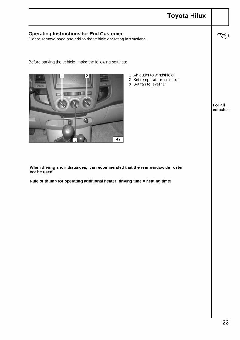
Operating Instructions for End CustomerPlease remove page and add to the vehicle operating instructions.
Before parking the vehicle, make the following settings:
1 Air outlet to windshield2 Set temperature to "max."3 Set fan to level "1"
For all vehicles
47
1 2
3
2323
Toyota Hilux
b
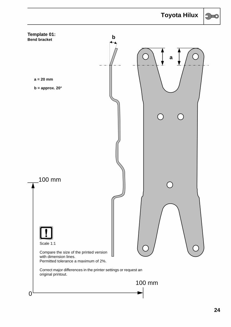
Template 01:Bend bracket24
a
a = 20 mm
b = approx. 20°
0
100 mm
100 mm
Scale 1:1
Compare the size of the printed version with dimension lines.Permitted tolerance a maximum of 2%.
Correct major differences in the printer settings or request an original printout.
Toyota Hilux
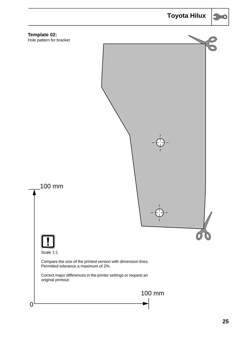
Template 02:Hole pattern for bracket
25
0
100 mm
100 mm
Scale 1:1
Compare the size of the printed version with dimension lines.Permitted tolerance a maximum of 2%.
Correct major differences in the printer settings or request an original printout.