Embed Size (px)
Citation preview

COMPOSITE WOUND AXIAL TURBOMACHINERY IMPELLER FOR GREEN-
RENEWABLE ENERGY: APPLICATIONS AND NUMERICAL STRUCTURAL
ANALYSIS
By
Mohit Shamkant Patil
A DISSERTATION
Submitted to
Michigan State University
in partial fulfillment of the requirements
for the degree of
Mechanical Engineering – Doctor of Philosophy
2014

ABSTRACT
COMPOSITE WOUND AXIAL TURBOMACHINERY IMPELLER FOR GREEN-
RENEWABLE ENERGY: APPLICATIONS AND NUMERICAL STRUCTURAL ANALYSIS
By
Mohit Shamkant Patil
Most of the major types of renewable energy cycles require a piece of turbomachinery. The
novel woven wheel turbo impeller concept has been in research for past few years. Most of the
previous research work focused on the early manufacturing concepts and aerodynamic studies.
The research aims to investigate: (a) feasibility of using the novel woven wheel impeller for
various applications in the energy industry and (b) understanding the mechanical structural and
vibrational behavior of the wound impeller. The application areas include renewable and
sustainable energy solutions like refrigeration using water as refrigerant, flash evaporation
geothermal power plants and tidal and marine power. Preliminary experiments establish the proof
of concept for employing the novel wheel impeller technology to these areas. A prototype single
stage compressor test loop for compressing water vapor was designed and built. Scaled up results
from the prototype testing show that it is possible to achieve the necessary pressure ratio across
multiple stages to compress water vapor using this concept. Application of the woven wheel
technology to tidal turbine applications is explored and proof of concept established with an
experiment in simulated conditions in a tow tank. The woven wheel turbine prototype was able to
generate a maximum of 2.5 KW power at 7 knots water velocity.
A methodology is developed to model these impellers using finite element methods to
structurally understand the mechanical behavior of the wound impellers. The vibrational
characteristics of the bare impeller have been studied and the Campbell plots mapped which

present an overall (or bird’s-eye) view of the regional vibration excitation that can occur on an
operating system. Effect of varying parameters like fiber type, shrouding, blade thickness, blade
twist angle, magnet positioning and magnet filler material on the structural behavior of the impeller
is studied and analyzed leading to an more enhanced design of the integrated rotor. It was found
that adding an additional shroud layer of composite material significantly strengthens the
integrated impeller.

Copyright by
MOHIT SHAMKANT PATIL
2014

v
ACKNOWLEDGEMENTS
I would like to express my deepest gratitude towards my advisor Dr. Norbert Müller, who
has supported me in my research path and my personal growth. I thank him for all the
encouragement, help and support that he has provided me all these years. His advice on both
research and career path has been invaluable. I wish him all the best for his future research and
personal life.
I would also like to thank my committee members Dr. Abraham Engeda, Dr. Elias Strangas
and Dr. Dahsin Liu for serving as my committee members and guiding me with their crucial advice
to improve my work. The work could not have been complete without the help and support of my
fellow lab mates Blake, TJ, Raul, Rohit, Marco and Chris. I thank them all for their help throughout
these years in graduate school.
Finally, I would like to thank my family and friends for their support throughout my
graduate school. A special thanks to my father Dr. Shamkant B. Patil for sparking my interest in
the field of science early on in my life and supporting me in every possible way through college
and graduate school.

vi
TABLE OF CONTENTS
LIST OF TABLES ..................................................................................................................... viii
LIST OF FIGURES ..................................................................................................................... ix
CHAPTER 1: INTRODUCTION AND DISSERTATION ORGANIZATION ..................... 1 1.1 INTRODUCTION .............................................................................................................. 1 1.2 PREVIOUS WORK ........................................................................................................... 2 1.3 RESEARCH OBJECTIVE ................................................................................................... 2
1.4 DISSERTATION ORGANIZATION ...................................................................................... 3
CHAPTER 2: COMPOSITE WOUND AXIAL IMPELLER FOR COMPRESSING
WATER VAPOR .......................................................................................................................... 5 2.1 WATER AS A REFRIGERANT ........................................................................................... 5 2.2 WATER VAPOR REFRIGERATION CYCLE ........................................................................ 8 2.3 AXIAL COMPRESSORS FOR R718 .................................................................................... 9
2.4 COUNTER-ROTATION ................................................................................................... 10 2.5 DESIGN OF TEST IMPELLER AND WEAVING PATTERN .................................................. 12
2.6 INVESTIGATED IMPELLER GEOMETRIES ....................................................................... 15 2.7 MANUFACTURING FACILITY ........................................................................................ 17 2.8 DESIGN AND MANUFACTURING PROCESS .................................................................... 19
2.9 FABRICATION OF WOUND/WOVEN IMPELLER WITH INTEGRATED MOTOR ROTOR
ELEMENTS .............................................................................................................................. 21 2.10 COMPRESSOR TEST LOOP ............................................................................................. 24 2.11 TEST RESULTS ............................................................................................................. 26
2.12 SIMILITUDE CALCULATION FOR PROOF-OF-CONCEPT AND FEASIBILITY ...................... 27 2.13 CHAPTER SUMMARY .................................................................................................... 31
CHAPTER 3: COMPOSITE WOUND AXIAL IMPELLER FOR REMOVAL OF NON
CONDENSABLE GASES .......................................................................................................... 33 3.1 GEOTHERMAL POWER PLANTS ..................................................................................... 33 3.2 NON CONDENSABLE GASES .......................................................................................... 34 3.3 CURRENT NCG REMOVAL TECHNIQUES ....................................................................... 35 3.4 MULTI-STAGE COUNTER-ROTATING AXIAL COMPRESSOR WITH INTEGRATED COMPOSITE
WOUND IMPELLERS FOR NCG REMOVAL................................................................................. 41
CHAPTER 4: STRUCTURAL ANALYSIS OF COMPOSITE WOUND IMPELLER ...... 48 4.1 COMPOSITE WOUND IMPELLER ..................................................................................... 48
4.2 NUMERICAL (FEA) MODEL ......................................................................................... 51 4.3 FEM MESH .................................................................................................................. 52 4.4 MESH CONVERGENCE .................................................................................................. 53 4.5 BOUNDARY CONDITIONS AND LOADING ...................................................................... 54 4.6 FEA SOLVER ............................................................................................................... 55 4.7 STATIC STRESS ANALYSIS AND RESULTS ...................................................................... 57

vii
4.8 DYNAMIC ANALYSIS AND RESULTS .............................................................................. 63
CHAPTER 5: STRUCTURAL OPTIMIZATION OF THE INTEGRATED COMPOSITE
WOUND AXIAL IMPELLER................................................................................................... 72 5.1 INTRODUCTION TO ANSYS ............................................................................................ 72
5.2 FINITE ELEMENT MODEL SETUP .................................................................................... 76 5.3 EFFECT OF FIBER TYPE .................................................................................................. 79 5.4 EFFECT OF ADDITIONAL SHROUD ................................................................................. 79 5.5 EFFECT OF NUMBER OF PLIES ....................................................................................... 81 5.6 EFFECT OF BLADE THICKNESS ...................................................................................... 82
5.7 EFFECT OF BLADE TWIST ANGLE .................................................................................. 82 5.8 OPTIMIZATION OF THE INTEGRATED ROTOR ................................................................. 86 5.9 EFFECT OF MAGNET FILLER MATERIAL ......................................................................... 88
5.10 EFFECT OF MAGNET ROTATION/POSITION ..................................................................... 90 5.11 OPTIMIZATION OF DESIGN ........................................................................................... 95
CHAPTER 6: COMPOSITE WOUND AXIAL IMPELLER FOR TIDAL TURBINE ...... 96 6.1 TIDAL POWER .............................................................................................................. 96 6.2 CURRENT TECHNOLOGY .............................................................................................. 98
6.3 PROPOSED TECHNOLOGY ........................................................................................... 100 6.4 EXPERIMENTAL SETUP AND RESULTS ........................................................................ 104 6.5 RESULTS .................................................................................................................... 110
6.6 FUTURE OF THE PROPOSED TECHNOLOGY .................................................................. 113
CHAPTER 7: CONCLUSIONS .............................................................................................. 115 7.1 SUMMARY .................................................................................................................. 115 7.2 CONTRIBUTIONS ........................................................................................................ 116
7.3 RECOMMENDATIONS AND FUTURE RESEARCH ........................................................... 116
REFERENCES .......................................................................................................................... 119

viii
LIST OF TABLES
Table 2.1 Typical winding patterns for continuous fiber wound impeller ................................... 15
Table 2.2 Six Cases Studied for the Axial Compressor ................................................................ 16
Table 2.3 Summary of performance for each case ....................................................................... 17
Table 2.4 Experimental pressure differences achieved ................................................................. 27
Table 3.1 Efficiencies of typical NCG removal systems .............................................................. 41
Table 4.1 Mechanical properties of composites ........................................................................... 50
Table 4.2 Natural Frequencies with and without the effect of centrifugal loading ...................... 65
Table 5.1 Mechanical properties of the composite layup ............................................................. 77
Table 5.2 Effect of fiber type on the structural strength of the impeller ...................................... 79
Table 5.3 Effect of additional shroud on the structural strength of the impeller .......................... 80
Table 5.4 Effect of number of plies (same total thickness) on the structural behavior of
impeller .................................................................................................................... 82
Table 5.5 Effect of blade twist angle on the structural behavior of the impeller .......................... 84
Table 5.6 Mechanical properties of the magnets and the magnet spacer materials ...................... 89
Table 6.1 Description of the town tank facility .......................................................................... 110
Table 6.2 Summary of the measurements showing the TSR and Power Coefficient ................. 112

ix
LIST OF FIGURES
Figure 1.1 Woven wheel impeller application areas ....................................................................... 1
Figure 2.1 Schematic diameter comparison for axial and centrifugal compressors of same
capacity ...................................................................................................................... 9
Figure 2.2 Power density comparison between conventional unidirectional impeller that
requires stationary guide vanes and counter-rotating impellers that can eliminate
stationary guide vanes and increase power density up to 3 times ........................... 11
Figure 2.3 Alternative Winding Patterns. Left: One Complete Layer of Continuous Fiber
Winding; Left Center: Multiple Complete Layers of Continuous Fiber Winding;
Right Center: Computer Model Wound with Single Continuous Fiber; Right:
Shorter Axial Length Impeller with Smaller Fiber Thickness ..................................... 12
Figure 2.4 (left) Winding pattern computer simulation, (center) wound impeller with mandrel,
(right) wound Kevlar impeller ................................................................................. 14
Figure 2.5 Two separate rotor patterns (8B & 8C) with different hub/tip ratios .......................... 16
Figure 2.6 Layout of filament winding facility ............................................................................. 18
Figure 2.7 8-Slot Pattern Mandrel ................................................................................................ 20
Figure 2.8 Three Ways of Integrating a Motor at the Outer Shroud Three Ways of Integrating a
Motor at the Outer Shroud. Left: Thin Shell or Sleeve Motor Fitted over the Outer
Shroud; Center: Individual Elements located at Inner Diameter of Outer Shroud;
Right: Integrated into the Composite Material ........................................................... 22
Figure 2.9 Top left: Exploded view of the integrated motor rotor with the composite impeller at
the center; Top right: Assembled view of the integrated motor, bearing and the
wound wheel; Bottom left: Permanent Magnet Poles Integrated with Outer Shroud;
Bottom right: Fully Integrated with Impeller ............................................................. 23
Figure 2.10 Test Loop with Counter-Rotating Wound Impellers ................................................. 24
Figure 2.11 Data acquisition system for the test loop ................................................................... 25
Figure 2.12 Wound Kevlar Wheels as seen from inside the loop ................................................. 26
Figure 2.13 Pressure Differences vs Rotational Speed ................................................................. 26
Figure 2.14 Pressure Difference and Pressure Ratio vs Rotating Speed for 10cm Diameter
Impellers .................................................................................................................. 29

x
Figure 2.15 Pressure Difference and Pressure Ratio vs Rotating Speed for 47cm Diameter
Impellers .................................................................................................................. 30
Figure 3.1 Steam jet ejector (Source: Graham-mfg) ..................................................................... 36
Figure 3.2 Geothermal flash power plant with a steam ejector .................................................... 37
Figure 3.3 Liquid ring vacuum pump (LRVP) (Source: Graham-mfg) ........................................ 38
Figure 3.4 GE SRL 903 installed at geothermal power plant in Le Prata, Italy (Source: GE
power systems) ........................................................................................................ 39
Figure 3.5 Cost of electricity production for NCG removal systems (13% NCG) [34] ............... 40
Figure 3.6 Possible installation scheme, Upright configuration ................................................... 42
Figure 3.7 Prototype Composite Integrated Impellers (left) Kevlar/epoxy, (right)
Carbon/epoxy ........................................................................................................... 44
Figure 3.8 Single stage counter rotating setup of the prototype compressor ................................ 45
Figure 3.9 First prototype of 10 stage counter-rotating NCG compressor installed in
geothermal power plant for testing .......................................................................... 46
Figure 3.10 Geothermal power plant upgraded to a multi-stage axial compressor for NCG
removal .................................................................................................................... 47
Figure 4.1 Kevlar wound composite impeller with its dimensions .............................................. 49
Figure 4.2 Specific Strength of Kevlar-49, Carbon and S-Glass fibers ........................................ 50
Figure 4.3 Geometrical model of the impeller showing the material co-ordinate systems .......... 51
Figure 4.4 C3D4 element .............................................................................................................. 52
Figure 4.5 Meshed model showing all the coordinate systems .................................................... 53
Figure 4.6 Mesh Convergence ...................................................................................................... 54
Figure 4.7 Boundary Conditions ................................................................................................... 55
Figure 4.8 Maximum Stresses for different composites at operating conditions ......................... 59
Figure 4.9 Maximum nodal displacements under operating conditions ....................................... 59
Figure 4.10 Maximum Normalized stresses (normalized to failure stress) for different
composites at operating conditions .......................................................................... 60
Figure 4.11 Stress plots. Red color indicates failure zones .......................................................... 62

xi
Figure 4.12 First 10 Mode shapes for a Kevlar-49/Epoxy impeller with no centrifugal loading.
The contours denote the U magnitude. .................................................................... 64
Figure 4.13 Change in modal frequency due to centrifugal stiffening. ....................................... 66
Figure 4.14 Campbell Plot for Kevlar-49/Epoxy impeller ........................................................... 68
Figure 4.15 Campbell Plot for Carbon/Epoxy impeller ................................................................ 69
Figure 4.16 Campbell Plot for S-Glass/Epoxy impeller ............................................................... 70
Figure 5.1 Flowchart summarizing the key analysis steps with ANSYS WB .............................. 75
Figure 5.2 Right: Actual woven wheel impeller, Left: Meshed model of the woven wheel in
ANSYS ACP............................................................................................................ 76
Figure 5.3 Effect of additional shrouding on the deformations of the impeller ........................... 81
Figure 5.4 Meshed impeller for various blade twist angles .......................................................... 83
Figure 5.5 Effect of blade twist angle on the maximum blade deflection .................................... 84
Figure 5.6 Effect of blade twist angle on impeller deflections ..................................................... 85
Figure 5.7 Integrated rotor impeller with dimensions .................................................................. 86
Figure 5.8 Finite element meshed model of the integrated rotor with additional shroud and
outer wrap ................................................................................................................ 87
Figure 5.9 Maximum rotor stress for different magnet spacer materials ...................................... 89
Figure 5.10 Maximum radial deflections of the rotor for different magnet spacer materials ....... 90
Figure 5.11 Effects of magnet position on impeller stresses ........................................................ 91
Figure 5.12 Effect of magnet position on the impeller shroud deflections ................................... 92
Figure 5.13 Effect of magnet position on the impeller blade deflections ..................................... 92
Figure 5.14 0o reference magnet location with respect to the inlet blade tip ................................ 93
Figure 5.15 3o reference magnet location with respect to the inlet blade tip ................................ 93
Figure 5.16 8o reference magnet location with respect to the inlet blade tip ................................ 94
Figure 5.17 24o reference magnet location with respect to the inlet blade tip .............................. 94
Figure 6.1 Open Hydro Open-Centre Turbine .............................................................................. 99

xii
Figure 6.2 Marine life collision contour for a turbine in water .................................................. 102
Figure 6.3 Front view of the Woven wheel turbine inside the tow tank ..................................... 103
Figure 6.4 Woven wheel turbine setup being submerged into the tow tank ............................... 104
Figure 6.5 Side view of the Woven wheel turbine inside the tow tank ...................................... 105
Figure 6.6 Woven wheel turbine with the power transmitting mechanism ................................ 106
Figure 6.7 Load cells used for braking torque measurement ...................................................... 106
Figure 6.8 Top view of the Woven wheel turbine inside the tow tank ....................................... 107
Figure 6.9 Picture showing the end view of the tow tank facility .............................................. 108
Figure 6.10 Disk brake system with load cell underneath for braking torque measurement ...... 109
Figure 6.11 Data acquisition for measuring turbine rotational speed, load cell reading and
moving carriage speed ........................................................................................... 109
Figure 6.12 Plot showing the measured torque, power and carriage speed as a function of the
rotational speed of the turbine as the carriage moves from one end to another .... 111
Figure 6.13 Conceptual design showing stackable modular turbines tethered to seabed. .......... 113
1
CHAPTER 1: INTRODUCTION AND DISSERTATION
ORGANIZATION
1.1 INTRODUCTION
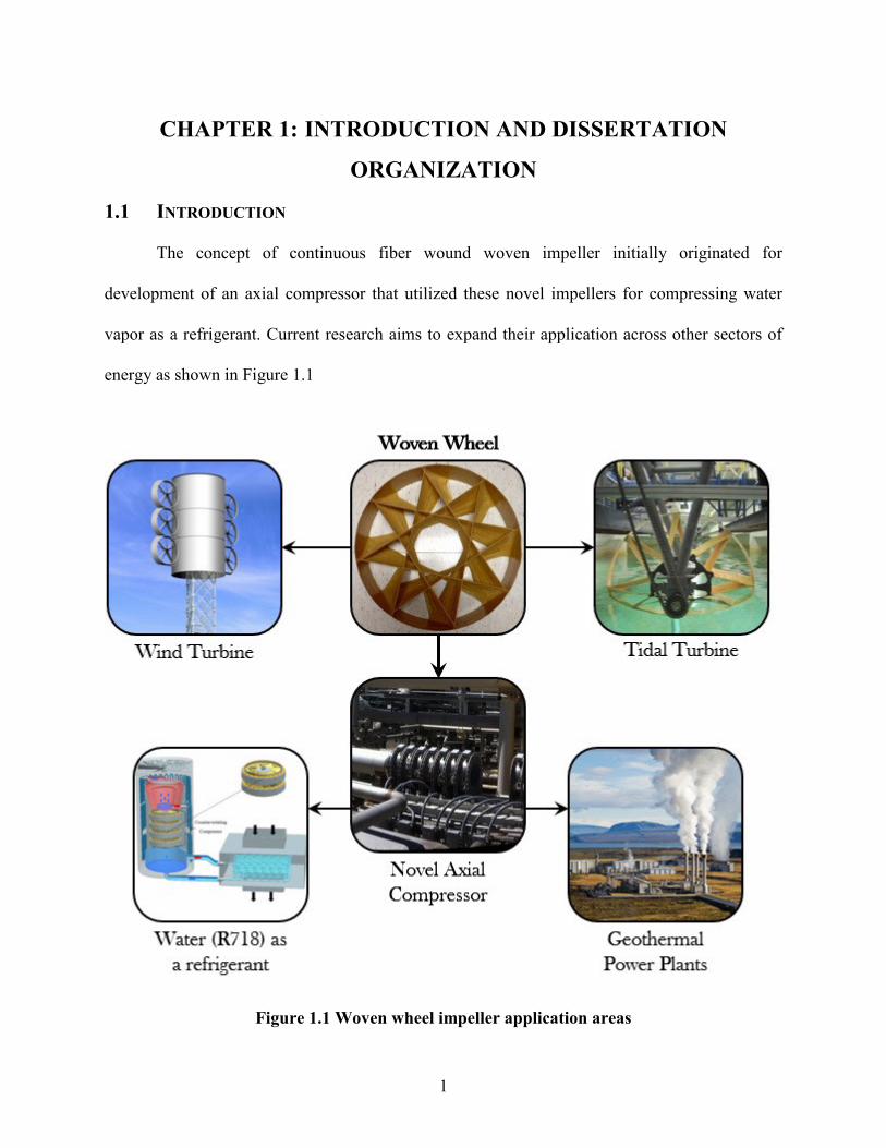
The concept of continuous fiber wound woven impeller initially originated for
development of an axial compressor that utilized these novel impellers for compressing water
vapor as a refrigerant. Current research aims to expand their application across other sectors of
energy as shown in Figure 1.1
Figure 1.1 Woven wheel impeller application areas

2
1.2 PREVIOUS WORK
The previous work associated with the design and development of the novel wound
impeller was mostly relevant to compressing water vapor. A lot of work was done comparing the
theoretical performance of water vapor R718 with other conventional refrigerants. CFD analysis
was done comparing various wound patterns and their aerodynamic performance. Qubo Li [1]
found that the impeller design pattern 8-B was the most promising option for generating higher
pressure ratios.
The relevant previous work is summarized in the bullet points below:
Thermodynamic cycle analysis of water vapor refrigerant
Woven wheel technology for multi stage axial turbo compressor for R718
refrigerant
Manufacturing methodology for bare composite impeller
Mechanical characterization of the woven wheel
Aerodynamic comparison of patterns and flow structure for various hub/tip ratios
1.3 RESEARCH OBJECTIVE
The main goal of the current research is to explore, investigate and establish feasibility of
using the woven wheel technology to not only compressing water vapor as a refrigerant but also
areas like geothermal power and tidal power. This includes researching the current technology in
these fields and proposing a better solution with the woven wheel technology. The feasibly and
viability is established by demonstrating proof of concept experiments. The second goal of the
research is to study the structural behavior of these novel impellers using 3-D Finite Element
Methods. Using FEA the effect of each parameter like fiber type, blade thickness, blade twist angle

3
etc. on the structural integrity of the impeller is studied. The technical objective that the research
aims to fulfill are as below:
1. To demonstrate the feasibility of manufacturing and using a single stage counter-
rotating integrated impeller axial compressor for compressing water vapor using a
prototype experimental setup and similitude calculations.
2. Develop a 3-D FEA model of the impeller to predict the structural and vibrational
response of the impeller at operating conditions.
3. Identify the effect of each geometric parameter on the structural behavior of the
impeller.
4. Using all the data, generate a structurally optimized design of an integrated impeller
with permanent magnets and magnet spacers.
5. To demonstrate the feasibility of using the woven wheel technology for a tidal
turbine application by building a prototype and conducting experiments in
simulated conditions like a tow tank.
1.4 DISSERTATION ORGANIZATION
Chapter 2 demonstrates the feasibility of winding/weaving light-weight, high-strength
composite turbo-impellers with integrated motor and bearings on a commercially available
winding machine. Results from a small scale compressor test loop in conjunction with a similitude
calculation provide a proof of concept and feasibility.
Chapter 3 introduces a novel new technique for removal of non-condensable gases from
flash steam geothermal power plants. A multi stage axial compressor with composite wound
impellers built on the patented woven wheel design approach is employed for the non-condensable
gases removal.

4
Chapter 4 describes the structural analysis procedure using finite element methods for the
wound axial impeller that can be used in a multistage counter rotating axial compressor for
compressing water vapor (R718). Through means of FEA (Finite Element Analysis) method;
stress, displacement and vibration analysis procedure is developed to assess the maximum stress,
change in dimensions and natural frequencies of these impellers under constant operating
conditions
Chapter 5 focuses on structural analysis and design optimization of an integrated rotor.
This design has permanent magnets on the outer shroud of the impeller as a part of the rotor.
Chapter 6 describes the woven wheel tidal turbine. Its merits over the conventional
technology and presents an experimental proof of concept.
Chapter 7 presents the summary of conclusions of the research work with
recommendations for future work.

5
CHAPTER 2: COMPOSITE WOUND AXIAL IMPELLER FOR
COMPRESSING WATER VAPOR
This chapter demonstrates the feasibility of winding/weaving light-weight, high-strength
composite turbo-impellers with integrated motor and bearings on a commercially available
winding machine. This can provide a very much needed scalable and economical multi-stage
counter-rotating axial compressor which uses water (R718) as the refrigerant. The benefits of water
as a natural refrigerant are briefly explained and the current state of art discussed. The design and
various weaving patterns for the wound composite (Kevlar-49) impeller are introduced along with
the manufacturing set up and the fabrication process. Results from a small scale compressor test
loop in conjunction with a similitude calculation provide a proof of concept and feasibility.
2.1 WATER AS A REFRIGERANT
Water has been used as a refrigerant for air-conditioning and for the production of ice using
steam ejectors, large centrifugal compressors, and has been promoted for the use with large high-
speed axial compressors. The future of water as a refrigerant for vapor compression refrigeration
depends either on the innovative designs of the cycle, or the development of high-speed axial
compressors to operate at the very low pressures required for R718 refrigeration.
The key component of a R718 turbochiller is the compressor, since as other components
can be comparably simple and water as a refrigerant has some specific features that complicate its
application in mechanical compression refrigeration plants. Since the cycle works under coarse
vacuum, the volumetric cooling capacity of water vapor is very low. Hence, huge volume flows
have to be compressed with relatively high pressure ratios. Therefore, the use of water (R718) as
a refrigerant, compared to classical refrigerants such as R134a or R12, requires approximately 200
times the volume flow, and about twice the pressure ratio for the same applications. Because of

6
the thermodynamic properties of water vapor, this high pressure ratio requires approximately a
two- to four-times higher compressor tip speed depending on the impeller design, while the speed
of sound is approximately 2.5 times higher. Reynolds numbers are about 300 times lower and the
specific work transmission per unit of mass has to be around 15 times higher.
This states the challenges for the compressor design. Today many of these challenges are
successfully solved in commercial industrial plants that are mainly installed in Europe using
unique high-performance mixed-flow turbocompressors with or without stationary guide vanes.
Other concepts are under investigation, like mixed flow compressors with inducer, pre-runner, or
axial multistage compressors, which promise a higher pressure ratio or a more compact design.
High pressure ratios are obtained by the combination of high rotational speed and large diameter,
where the diameter is primarily limited by the available space in a manufacturing facility and
installation. Since R718 compression systems work under coarse vacuum, the forces on the
impeller blades are mostly due to the centrifugal force generated by its own mass spinning at high
speeds rather than those generated by the fluid’s dynamic action on the blades. This has been
providing the opportunity of more economic, lightweight constructions that have been realized
with extremely thin, mostly straight blades made of special materials like titanium or composites.
These impellers are very much different from usual high-performance impellers. They cannot be
milled: they are comprised of several parts, indicating a challenge for manufacturing and balancing
of the high-speed system. Development of a variable speed direct-drive motor working under
vacuum in a water vapor atmosphere requiring special bearings, cooling, and electrical isolation is
critical to the success of such systems. Furthermore, R718 turbochillers have lower noise emissions
and require no special safety installations concerning drainage and ventilation. R718 turbochillers

7
represent cutting edge technology. They allow a move towards greener technology with a huge
potential for application and manufacturing even outside of Europe.
To offset the continuous threat of global warming and ozone depletion, regulations and
bans of traditional refrigerants have been handed down by governments and agencies. Because of
this, the development of natural refrigerant technologies, such as using water (R718) as a
refrigerant, are necessary. Water is completely benign to the environment and has many
environmental advantages over traditional refrigerants. Practically, it has no global warming
potential (GWP = 0) and no ozone depletion potential (ODP = 0). In addition, it is non-toxic, and
non-flammable. Water can easily be disposed of and needs no manufacturing or extensive refining.
While traditional refrigerants meet today’s restrictions and standards, it is almost inevitable that
these restrictions are bound to change. Water can be guaranteed not to fall under future restrictions.
In addition to its many environmental benefits, R718 also includes several economic
advantages. The first and probably most obvious advantage is the availability of R718. Water
covers roughly two thirds of the Earth’s surface. Special treatments are often not needed.
Municipal tap water can be used, as well as filtered river or stream water. Treated waste water is
another possibility. Since the refrigerant is so readily available and distributed by existing
infrastructure, there would be no need to warehouse and transport bulky refrigerant containers.
The gross cost of the refrigerant is less, since water needs no special manufacturing as well. R718
also reduces safety precautions by working with low pressure differences (less than 1 atm). This
can cut down on insurance premiums as well.
When discussing economic benefits, it is important to include the energy efficiency of
R718 units. Thermodynamically, water can be shown to achieve a high coefficient of performance
(Equation 1). Studies have shown that R718 chiller technology can be 20-30% more energy

8
efficient than conventional refrigerant technology [2]. Unlike other refrigerants, R718 can be used
in direct heat exchangers, increasing efficiency. Furthermore, installed units have shown high
availability, high efficiency, low maintenance, and low operating costs [3].
2.2 WATER VAPOR REFRIGERATION CYCLE
Kilicarslan and Müller [4] showed that water has ideal properties to be used as a refrigerant.
For single stage compression, R718 has a comparable efficiency to certain conventional
refrigerants for a given standard operating temperature range in the evaporator, and temperature
differences between the evaporator and condenser. Considering its environmental friendliness and
availability, they stressed the need to develop suitable multi-stage turbo compressors for a wider
range of applications. Orshovn et al. [5] explored potentials and limitations of water as a refrigerant
for refrigeration and heat pump applications above its freezing point. They showed water can be
used both as a viable refrigerant and as a heat transfer medium for applications such as ice
production. Noting the large diameter of a centrifugal compressor required to handle the decidedly
large volume flow rates, they concluded that innovation is required in vacuum compression
technology to use water as the working fluid in vapor compression refrigeration cycles. Lachner
et al. [6] investigated the economic feasibility of a water-based vapor compression chiller with a
nominal cooling capacity of 1000 tons using component-level modeling to determine the system
performance by simulating various cycle configurations. The capital cost and operating costs of
the system were estimated, as was the payback period predicted for a system that utilizes turbo
compressors. Although, at that time, it was concluded that the use of water as refrigerant was not
feasible, they did not consider that water could be used simultaneously as the refrigerant as well
as the heat transfer medium. Kuhnl [7] discussed the realization of chillers using water as
refrigerant by employing flash evaporation cooling, a direct-contact type of condenser, and chilled

9
water circulation from the evaporator to the cooling points. Kuhnl concluded that due to the small
temperature difference required between the inlet and outlet of direct contact condensers, the
system can have a better performance than systems employing other refrigerants. The
disadvantages again were the huge size of the compressor and its high cost as compared to
conventional systems.
2.3 AXIAL COMPRESSORS FOR R718
The concept of using axial compressors for R718 cycles has been introduced before by
numerous researchers [8]. However, apparently due to the price of axial multistage gas turbine
compressors this has not been commercialized for R718. With the here presented innovative
wound impellers, the use of axial compressors for R718 becomes feasible due to the dramatic cost
reductions. Axial compressors are known for their compactness and high efficiency [9]. Axial
compressors, in general, have much smaller diameter than radial or mix-flow compressors for the
same capacity as illustrated in Figure 2.1.
Radial
guide vanes
(red)
4x d
iam
ete
r of a
xia
l sa
me
ca
pa
city c
om
pre
ssor
Axial Counter-rotating
Figure 2.1 Schematic diameter comparison for axial and centrifugal compressors of same
capacity

10
This is because the suction cross sectional area is approximately the same for both types
for the same capacity. Using the ILK compressor as a reference [10], with an inlet diameter of
approximately 0.5m, 1m wheel diameter, and 2m overall diameter including the radial diffuser, an
axial compressor for same capacity typically would have a constant outer diameter of
approximately 0.5 m, reducing the diameter approximately by ¾ to only 25% of that required for
a radial compressor. The volume reduces with the square of diameter. While this simple approach
gives a volume reduction by an amazingly large factor of 16, it is to be noted that a conventional
axial compressor of same pressure ratio typically has a greater axial length than its centrifugal
compressor counterpart due to the smaller pressure ratio achievable for a single stage, hence the
need for multi-staging. A conservative estimate can still yield an overall volume reduction by a
factor of about 10 when including the motor dimensions required to spin a multi-stage system and
when compared to a centrifugal compressor with motor. This volume reduction is further
guaranteed by utilizing counter-rotation.
2.4 COUNTER-ROTATION
The design of impeller-integrated motors allows for easy implementation of counter-
rotating wheels, which before always has created problems for implementing the drive
mechanically, especially for more than two wheels. The main advantage of counter-rotation is the
possible elimination of stationary guide vanes that are necessary to redirect the flow in uni-
directional rotating stages of conventional design. Two counter-rotating wheels without guide
vanes allow for swirl-free flow before and after such stage. It has already been shown that for state-
of-the-art unidirectional compressors with inlet guide vanes (IGV, then called inducer or pre-
runner) with the same tip speed as the main centrifugal compressor wheel, work transmission can

11
more than double (140%) [11] [12]. Higher work transmission translates directly into higher
pressure ratio, thereby reducing the number of stages required.
Figure 2.2 Power density comparison between conventional unidirectional impeller that
requires stationary guide vanes and counter-rotating impellers that can eliminate
stationary guide vanes and increase power density up to 3 times
Stationary guide vanes do not transmit work, while they add mass, volume, frictional
surfaces, and costs to the system. Further, if they are not adjustable, they can limit the operating
range. Eliminating them can dramatically compact the compressor, while improving performance
and operational flexibility. Figure 2.2 demonstrates schematically how counter-rotation can
enhance volumetric power density by up to three times. The conventional system (Figure 2.2a)
with IGV and diffuser guide vanes has only one work transmitting (rotating) wheel. The counter-
rotating version (Figure 2.2b) with two work transmitting wheels gives double work transmission
at 2/3 volume, and the counter-rotating version (Figure 2.2c) with three work transmitting wheels
results in three times the work transmission within the same volume as the conventional system.
Mass can be expected to be somewhat proportional to volume. With wheel-integrated motors, work
transmitting shafts and their support structures are also eliminated, further reducing, parts, mass,
and costs.

12
2.5 DESIGN OF TEST IMPELLER AND WEAVING PATTERN
One of the major challenges with the use of fiber-reinforced composite materials for the
blades is the mechanical connection of the blades to the torque transmitting elements like the hub
and the shaft. The largest stresses in the impeller are found in the area where the blades connect to
the hub, which in turn connects to the shaft. This poses limits to such designs. Blades also can
break when flexing at this location. The majority of the forces experienced by an R718 compressor
wheel are not from the vapor passing over the blades, but centrifugal forces acting in the radial
direction due to the mass of its own material when rotating at high speeds. Because of this, the
impeller must be constructed of strong and light-weight material. Also, the lighter the impeller is,
the less the safety risks are, and the less the forces are exerted on the bearings. Light weight
constructions also reduce the need for extensive balancing. An integrated composite construction
solves most of these problems. In which case, continuous fibers laid in the force direction allow
the strong fibers to counteract these centrifugal forces without the need for additional mechanical
connections or couplings.
Figure 2.3Alternative Winding Patterns
Left: One Complete Layer of Continuous Fiber Winding
Left Center: Multiple Complete Layers of Continuous Fiber Winding
Right Center: Computer Model Wound with Single Continuous Fiber
Right: Shorter Axial Length Impeller with Smaller Fiber Thickness

13
The mandrel for winding the continuous fiber wheels can be held by a rotating 3-jaw self-
centering chuck of a winding machine (CNC). All winding patterns preferably results in a design
with an outer shroud and fibers in force direction when rotated at high speeds. The outer shroud
widely diminishes issues of blade tip vortices, tip leakage, tip clearance, and adds additional
strength in tangential direction, thus reducing vibrations. It also allows for an integrated motor at
the outer diameter. After the matrix material (resin) is hardened during or after the winding
process, the mandrel can either be removed (with the aid of a previously-applied mold-release
agent), or it can remain in the impeller as a structural element of the impeller especially if the
support is of magnetic material and used as electromagnetic element of an integrated motor or
bearing. Winding patterns like those shown in Figure 2.3 (and like several in Table 2.1) result in a
bladeless inner hub area that can be blocked off or house other elements like an axle, shaft, or hub
motor. These patterns also can provide additional flow guidance in the outer hub area that can aid
in preventing flow separation from the hub. Winding patterns like 6B and 8C (Table 2.1) have
radial-line blading. All patterns allow for curved blades.
There are many advantages to these designs, resulting in greatly reduced production costs:
The impeller can be mass-produced and rapidly prototyped on a readily available
multi-axis winding machine.
Fully automated CAD/CAM production is achievable for varying performance
parameters.
Different types of impellers are possible including mixed-flow impellers in addition
to axial-flow impellers.
The rotor can be built in a single production step without additional assembly.
Construction does not require the use of expensive dies, molds, or tooling.

14
Manufacturing processes also allow the integration of conductive or magnetic
material for an integrated induction or permanent magnet motor.
Furthermore, there are advantages compared to the state of the art that improve efficiency:
The design allows for aerodynamically curved blades, as well as a shaped hub
contour.
The design includes an outer shroud.
Some patterns allow for additional flow guidance, counteracting flow separation
from the hub, insuring a wider range of efficient operation.
A computer code that is universal for several weaving patterns using dimensional inputs
like diameter, blade number (mandrel slots), pattern qualifiers, fiber radius, and fiber thickness can
produce the required input data for manufacturing. With this also a physical model of the impeller
using a rapid prototyping machine as shown in Figure 2.4 was generated. In the figure, the outer
shroud of the impeller is represented as a circle. The points at which the lines start through the
interior to intersect the circle are referred to as nodes or edge points. The basic shape of the
impeller model is created by lines and arcs drawn from one node to another. The preparation of
Figure 2.4 (left) Winding pattern computer simulation, (center) wound impeller with
mandrel, (right) wound Kevlar impeller

15
impeller design through computer code can easily enable an automatic filament winding
manufacturing process through CAD software in the CNC machine. An economical CNC machine
is used to manufacture the impeller.
2.6 INVESTIGATED IMPELLER GEOMETRIES
Table 2.1 summaries typical pattern shapes to weave.
Table 2.1 Typical winding patterns for continuous fiber wound impeller
Number of points on mandrel Shape-A Shape-B Shape-C
5
- -
6
-
7
-
8
9
For aerodynamic comparison, two different initial rotor patterns, 8B and 8C, were selected
(based on ease of winding), and their impeller geometries are shown in Figure 2.5. Different
hub/tip ratios were compared investigating aerodynamic aspects of how these novel impellers in a
multi-stage configuration behave while compressing water vapor as a refrigerant. Table 2.2

16
summarizes all six cases that were investigated. For the comparison, the blade angle at shroud was
kept the same while changing the pattern and the hub/tip ratio.
Table 2.2 Six Cases Studied for the Axial Compressor
Case No Rotor Hub/Shroud radius ratio
1 8B 0.75
2 8B 0.54 3 8B 0.43 4 8C 0.75 5 8C 0.54 6 8C 0.43
The comparison between the six cases outlined in Table 2.3, were performed using the
commercial CFD package FLUENT [13].
Figure 2.5 Two separate rotor patterns (8B & 8C) with different hub/tip
ratios

17
Table 2.3 Summary of performance for each case
Case No Rotor Hub/Shroud radius
ratio Peak ΠC Peak ηC
Normalized Volume Flow
1 8B 0.75 1.162 68% 1.5 2 8B 0.54 1.121 65% 2.5 3 8B 0.43 1.107 64% 3.16 4 8C 0.75 1.163 73% 1 5 8C 0.54 1.124 65% 2.33 6 8C 0.43 1.115 66% 2.66
From these results, the pattern with the largest volume flow has been selected (shown in
gray in Table 2.3). For higher pressure ratios, additional counter-rotating wheels can be added in
multi-staging. Additionally, this pattern was found the easiest to wind, and is highly repeatable;
therefore this pattern was selected for fabrication. While only selected shapes have been
investigated in this study, many other shapes including conventional blade shapes are possible
depending on preference.
2.7 MANUFACTURING FACILITY
The facility to manufacture the composite impeller is similar to one used for traditional
filament winding, which is basically centered around four core pieces of equipment:
1) A computer with software linked to a CNC controller.
2) The winding device (4-axis CNC machine).
3) The computer-controlled, custom-designed epoxy syringe system.
4) The fiber tensioning control system.
The CNC machine is the base of the entire system; the other subcomponents are integrated
on top of it. The facility layout is designed to fit into a limited workspace of approximately 1m by
1m with the ability to weave a maximum 0.15m diameter impeller. Referring to Figure 2.6, the
spools are mounted on the tensioning unit. This allows for taut Kevlar fibers to pass through the
static mixing tip that blends the epoxy with the hardening agent. The fiber tensioning unit consists

18
of a DC motor controlled through the computer, which is to provide constant torque to the fiber
applied opposite to the rotational direction (feed direction). Fiber from the spool then is laid up
onto the rotating mandrel. From start to finish, there are no significant turning angles in the fiber,
thus ensuring that the added force from the rotating mandrel is approximately equal to the constant
tension added on the fiber during the winding process.
As seen in Figure 2.6, the two-component epoxy syringe system plays the same role as a
resin bath in a traditional filament winding machine. In a traditional resin bath the resin has a
limited pot life. Therefore as time passes, the resin can begin to harden before all of the fiber to be
wet-wound has been properly wetted this results in no-homogeneous properties of the final
composite. Thus, in place of the traditional resin bath, a custom designed two-component syringe
system is used to mix the resin with the hardener quasi-continuously from small batches supplied
to the syringes, producing a woven wheel with homogeneous properties. During the winding
process, when the mixed epoxy at the tip of syringe system is nearing depletion, the computer
MTraverse motion
motor
Mandrel motor
Kevlar fiber
motor
DSPPosition feedback
MM
Fiber spool
DSP
Tension control feedback
M
Linear actuator speed control
Two component
Epoxy syringe system
MM
MM
creel
Tensioning
unit
MTraverse motion
motor
Mandrel motor
Kevlar fiber
motor
DSPPosition feedback
MM
Fiber spool
DSP
Tension control feedback
M
Linear actuator speed control
Two component
Epoxy syringe system
MM
MM
creel
Tensioning
unit
MTraverse motion
motor
Mandrel motor
Kevlar fiber
motor
DSPPosition feedback
MM
Fiber spool
DSP
Tension control feedback
M
Linear actuator speed control
Two component
Epoxy syringe system
MM MM MM
MMM
creel
Tensioning
unit
Figure 2.6 Layout of filament winding facility

19
controlled linear actuators push the syringe plungers to inject the desired amount (~0.1ml) into the
static mixer at the tip. By using this approach, the passing fiber is always impregnated with freshly
mixed epoxy, ensuring the quality of the woven composite structure.
2.8 DESIGN AND MANUFACTURING PROCESS
The mandrel is made from aluminum tubing, which is milled using the CNC machine to
create the slots to enable winding. Depending on the impeller design in terms of inlet and outlet
blade angle as well as geometry (see Table 2.1), the CNC can be programmed to create the
appropriate slotting pattern on the mandrel and follow such when the impeller is wound. The
number of slots determines the number of blades possible, and the shape of the circular, elliptical,
or other curve contains the information for impeller inlet and outlet angle. Figure 2.7 shows an
example pattern for an 8-slot curved blade mandrel.
The CNC machine operates via computer control within the confines of four axes:
traversing carriage (x), longitudinal movement (y), height adjustment (z), and rotation within the
x-y plane (θ), while even lesser axii of freedom can be used productively. With these movement
options, the winding path to create one basic layer of the desired pattern can be completed. This
can be achieved by maintaining the same height (z-direction) while the mandrel rotates (θ-
direction), and the tip controlling the exact fiber placement moves in the x-y plane in order to feed
the previously wetted fiber through the slots. For automatic filament winding processes, the
wheel’s pattern is typically generated offline using CAD software (here NX6).

20
During the manufacturing process, the wheels were wound at a tension of about 1N, which
is regulated through the DC motor controller by adjusting the motor torque given the spool radius.
Studies show that increasing winding tension would raise the fiber volume fraction slightly and
therefore may have a significant effect on strength [14]. However, the tension on the fibers is
maintained at magnitude small enough that the issue of strength altering is not considered to be a
factor; the tension was kept mainly to enable clean and consistent windings that are highly
repeatable
The filament wound composite wheels were cured at room temperature overnight and were
kept rotating during the entire curing process to prevent sagging and the dripping of excess resin.
The cured composite impellers are then separated from the mandrel with the aid of a mold release
applied a priori. The resulting wheels were measured and found to have an average internal
diameter of 130.3mm and an average external diameter equal to 131.2mm, which includes the
external resin rich layer outside of the laminate layer. The surface roughness can also be controlled
during manufacturing and adapted to our advantage. The rough surface can act as micro
turbulators, enhancing the flow and controlling the boundary layer separation. Although no study
Figure 2.7 8-Slot Pattern Mandrel

21
has been done to prove the effect of surface roughness on the flow, it is very similar to the micro
scales and micro voids on the surface of shark skin. Scales of fast-swimming sharks have been
implicated in drag reduction [15] [16].
2.9 FABRICATION OF WOUND/WOVEN IMPELLER WITH INTEGRATED MOTOR
ROTOR ELEMENTS
In various ways, the woven design allows for the flexibility of integrating all rotating parts
of the drive into the rotor of the electrical motor. It also totally eliminates the need for a drive shaft.
This reduces parts, mass, and serves to compact the design. In a more conventional design, the
motor is integrated in the hub of a winding pattern. Integrating the motor in the outer shroud
provides several advantages that include:
For the same torque, the tangential forces on the rotor structure driving it are much
smaller due to the larger radius.
The tangential forces act at the outer radius where the radial stresses due to
centrifugal forces are smallest.
The active parts (coils) of the motor can be outside of the water vapor vacuum
atmosphere, dramatically reducing the electrical insulation requirements, hence
reducing costs and failure risks.
Ease of adopting a wide variety of various cooling methods including air cooling.
Better access to components

22
For reduced losses, a permanent magnet type motor is implemented. There are generally three
ways to incorporate the motor elements in the outer shroud of the impeller (Figure 2.8).
1) A thin shell or sleeve motor may be fitted at the outer diameter of the composite
impeller.
2) The motor elements may be located at the inner radius of the outer shroud, which
also can serve as support during winding.
3) The motor elements may be incorporated within the outer shroud. This can be
achieved in either of the following two ways:
I. By interweaving conductive fibers (wires) for an induction type,
II. Incorporating magnetizeable material in the form of fiber or matrix material for
permanent magnet type.
Figure 2.8 Three Ways of Integrating a Motor at the Outer Shroud
Left: Thin Shell or Sleeve Motor Fitted over the Outer Shroud;
Center: Individual Elements located at Inner Diameter of Outer Shroud;
Right: Integrated into the Composite Material

23
Figure 2.9 Top left: Exploded view of the integrated motor rotor with the composite
impeller at the center, Top right: Assembled view of the integrated motor, bearing and the
wound wheel
Bottom left: Permanent Magnet Poles Integrated with Outer Shroud
Bottom right: Fully Integrated with Impeller
In the tested version (Figure 2.9), 12 sets of rotor magnet poles of 4x4 small neodymium
magnets were glued equidistantly onto the surface of the outer metallic shroud made from 0.5 inch
steel tubing. The stator was modified to hold the woven wheel rotor. When integrated with the
filament wound impeller, the mandrel itself can be used as the motor rotor.

24
2.10 COMPRESSOR TEST LOOP
An experimental test loop was setup to demonstrate the performance of these small
impellers at various rotational speeds. Figure 2.9 shows the impeller integrated with the motor.
Figure 2.10 shows the test loop setup. The loop itself was constructed with high quality
shatter-proof clear plastic. The loop was clamped down at all four corners and the counter rotating
impellers for minimal vibrations. The loop was sealed with viton o-rings at the elbows and at the
inlets and outlets of the woven impeller compressor stages. Each of the two counter-rotating
impellers are housed in the black sections of the loop (between the metallic flanges linking the
sections of clear tubing that also hold all of the copper windings required for the permanent magnet
motor to operate). These test impellers have not been optimized aerodynamically. Pitot tubes and
manometers (Figure 2.11) were used to measure pressure differences across the compressor and
throughout the loop. In particular, the total-to-total pressure difference across the counter-rotating
impellers and the static-to-static pressure difference were recorded. Figure 2.12 shows a view of
the counter rotating setup from inside the loop.
Figure 2.10 Test Loop with Counter-Rotating Wound Impellers

25
The actual rotation of the impellers was controlled electrically using two brushless DC
motor controllers (one for each brushless DC motor). Each motor was a 12 pole (6 pole pair)
machine made out of large alternator stators. Each motor was driven by a 24V 60amp brushless
controller made for hobbyist applications. All power electronics to drive a two stage compressor
easily fits in a hand making this ideal for small compressor applications. The system control was
accomplished using an Arduino, a small integrated microprocessor based on the att Mega uC. A
fused variac connected to a simple rectification circuit provides the DC bus voltage and overcurrent
protection. A control system for control of a high speed BLDC motor has been designed and tested
in MATLAB Simulink. This design uses only current sensors for high speed closed loop control
of the motor. This was tested with the woven wheel motor using MATLAB and Labview.
Figure 2.11 Data acquisition system for the test loop

26
Figure 2.12 Wound Kevlar Wheels as seen from inside the loop
2.11 TEST RESULTS
For final setup, the motor controllers were able to spin the two counter rotating wheels at
a maximum speed of 2750rpm. The working fluid was humid air. Table 2.4shows the pressure
readings taken at various rotational speeds. Figure 2.13 shows the data from Table 4 graphically
Figure 2.13 Pressure Differences vs Rotational Speed
0.00
5.00
10.00
15.00
20.00
25.00
30.00
35.00
0 500 1000 1500 2000 2500 3000
Pre
ssu
re D
iffe
ren
ce (
Pa)
Rotational Speed (RPM)
Total-to-Total
Static-to-Static

27
Table 2.4 Experimental pressure differences achieved
Ambient Temperature 71°F 21.67°C
Relative Humidity 16% 16%
Ambient Pressure 29.89mmHg 101.202kPa
RPM Pressure Difference (Pa)
Motor 1 Motor 2 Total-to-Total Static-to-Static
500 -500 0.00 0.00
1000 -1000 2.49 0.00
2000 -2000 4.98 4.98
2100 -2100 9.96 7.47
2200 -2200 14.95 12.45
2750 -2750 32.38 29.89
2.12 SIMILITUDE CALCULATION FOR PROOF-OF-CONCEPT AND FEASIBILITY
The principle of similitude states that if two machines have similar geometries and are to
perform similar, there are dimensionless coefficients that remain constant. According to Potter’s
book Mechanics of Fluids [17] those coefficients include the Reynolds number (Equation 1),
Power coefficient (Equation 2), Pressure coefficient (Equation 3) and Flow coefficient (Equation
4).
lWRe
(1)
53
.
.
D
WC
W
(2)
22D
PCP
(3)
3D
QCQ
(4)

28
At the maximum achieved rotational speed during testing, the manometers recorded a
pressure difference of 32.38Pa (total-to-total) across the counter rotating impellers.
Using the principles of similitude, this data is scaled in different ways. Firstly it was
determined how the counter rotating impellers perform using pure water vapor near-vacuum
pressure (800Pa), rather than the ambient humid air used during testing. Secondly it was
determined how the counter rotating impellers would perform at much higher rotational speeds.
Lastly, it was determined how the counter rotating impellers would perform if their diameters are
scaled-up to working impeller size of approximately one half meter diameter.
In order to determine the pressure rise at the scaled conditions, the Pressure Coefficient in
Equation (3) must first be determined using measured values. Once complete, this can be equated
with the scaled conditions, and a new pressure rise can be determined based on the aforementioned
parameters.
22
_ similitudesimilitudesimilitudeMeasuredPsimilitude DCP (5)
1
1.05
1.1
1.15
1.2
1.25
1
21
41
61
81
101
121
141
161
181
0 20000 40000 60000 80000 100000
Pre
ssu
re R
atio
Pre
ssu
re D
iffe
ren
ce (
Pa)
Rotational Speed (RPM)
Similitude Pressure Difference
Similitude Pressure Ratio

29
Figure 2.14 Pressure Difference and Pressure Ratio vs Rotating Speed for 10cm Diameter
Impellers
For the first case, the pressure rise for the same size counter rotating impeller system was
calculated for pure water vapor under coarse vacuum (800Pa, 5°C) at various rotational speeds
using the maximum achieved pressure difference as the reference point for the measured
performance.
similitudeu
OHsimilitude
similitudesimilitudeMeasuredPsimilitudeTR
MWPDCP 222
_
(6)
Figure 2.14 shows a plot of both the pressure difference and pressure ratio versus rotational
speed. The maximum point on both curves corresponds to a tip speed of just under 450m/s. Again,
this tip speed is well within the mechanical failure limitations of the impellers as per a preliminary
FEA calculations, and it is required to achieve a large enough pressure ratio that a series of counter
rotating impellers could be used to compress water vapor as a refrigerant. However, the rotational
speeds required for this amount of compression is a challenge for impellers of this size.
Therefore, in order to reduce the operating speed of the drive system while maintaining the
required tip speed, the diameter of the impellers can be increased. For instance an impeller
diameter of approximately 0.5m results in much lower rotational speeds, higher volume flow, also
tip speeds below 500m/s, and a size that still would be possible to be automatically wound on a
similar CNC-based setup.

30
Figure 2.15 Pressure Difference and Pressure Ratio vs Rotating Speed for 47cm Diameter
Impellers
Figure 2.15 shows the similitude performance for the 0.47m setup with two counter rotating
wound impellers again in terms of both the pressure difference and pressure ratio achieved across
the compressor. It can be seen that within a rotational speed range of 15000rpm to 20000rpm that
the achieved pressure ratio is between 1.14 and 1.25 with the tip speeds as shown. Again, these tip
speeds are well below the tip speed expected to cause mechanical failure due to excessive
centrifugal force caused by the mass of the impeller rotating at high speed. It is quite feasible for
the system to operate between these rotational speeds with a long lifespan (the tip speed of 450m/s
corresponds to a rotational speed of 18285rpm and a pressure ratio of 1.2).
In order to achieve a high enough overall pressure ratio to compress water vapor under
coarse vacuum as a refrigerant, multiple counter-rotating impeller stages can be installed in series.
Depending on the actual cooling requirements of the refrigeration cycle using R718, the number
1
1.05
1.1
1.15
1.2
1.25
1.3
0
50
100
150
200
250
0 5000 10000 15000 20000 25000
Pre
ssu
re R
atio
Pre
ssu
re D
iffe
ren
ce (
Pa)
Rotational Speed (RPM)
Similitude Pressure Difference
Similitude Pressure Ratio
Tip Speed = 492m/s
Tip Speed = 370m/s

31
of counter-rotating stages using wound impellers can be determined from the standard pressure
ratio equation:
n
totalstage
/1 (7)
where n is the number of counter-rotating stages and is the pressure ratio. Based on the
results in Figure 2.15, the number of stages required for a given cooling requirement (Πtotal) is
stage
totaln
ln
ln
(8)
2.13 CHAPTER SUMMARY
The use of water as a refrigerant (R718) in the refrigeration application shows promise in
vapor compressor plants as water has distinct advantages over traditional refrigerants. However,
some of the difficulties that arise during manufacturing low-cost and high-performance
compressor impellers to compress this natural refrigerant still need to be addressed.
It has been illustrated that a novel manufacturing method similar to filament winding
technology is able to manufacture composite impellers for compressing water-vapor refrigerant at
a low cost. The feasibility of winding/weaving light-weight, high-strength turbo-impellers with
integrated motor and bearings on a commercially available winding machine has been successfully
demonstrated in this research project. These relatively small wheels have proven that an axial
woven impeller is capable of producing a pressure difference and hence pressure ratio across
multiple stages. Therefore, a larger version of the test loop with multiple stages will be able to
quite adequately produce the necessary pressure rise to induce cooling from compressed water

32
vapor. The reported performance data shall be interpreted as a starting point upon which
considerable improvements are possible, rather than a benchmark or ceiling that is already reached.

33
CHAPTER 3: COMPOSITE WOUND AXIAL IMPELLER FOR
REMOVAL OF NON CONDENSABLE GASES
This chapter introduces a novel new technique for removal of non-condensable gases from
flash steam geothermal power plants. A multi stage axial compressor with composite wound
impellers built on the patented woven wheel design approach is employed for the non-condensable
gases removal. This technique can be employed for new flash steam geothermal power plants and
used as an upgrade for current lesser efficient non condensable gases removal techniques like
steam ejectors. Harmful effects of the non-condensable gases are discussed and the current non
condensable gases removal techniques compared. Innovative aspects of the new technology are
explained with their advantages compared to current state-of-art.
3.1 GEOTHERMAL POWER PLANTS
Geothermal energy is primarily utilized by extracting dry steam or high-temperature liquid
water from an aquifer and by using the steam or the vapor of another substance for the production
of power with a turbine. Geothermal power can be produced by dry steam, flashed-steam, binary
and Kalina plants depending on the temperature and state of the geothermal fluid. Flashed-steam
(single and double-flash) geothermal power plants (GPPs) are the most commonly used power
generation systems with a total share of 61% within the installed capacity in the World, mainly
because most geothermal reservoirs are formed by liquid dominated hydrothermal systems [18].
Of this, 59% is single-flash plant [19] [20]. Because the geothermal fluid emanates from the
Earth’s interior and carries other substances, including solids and non-condensable gases, the
design of the equipment of a geothermal power plant poses several challenges, such as the
avoidance of scale in the well and flashing chambers; and the removal of non-condensable gases
from the condenser. The scales are usually formed by the ionic salts (NaCl, KCl, Ca2Cl, Ca2HCO3,

34
and CaCO3) dissolved in the water. If left untreated, the continuous deposition of the salts in the
pipe forms scales which over time will result in pipe restriction and eventual well clogging. In the
heat exchangers, these solids reduce the heat transfer coefficient by a considerable amount. Mild
acids like HCL are often used to dissolve and remove these salts further adding to the corrosive
conditions in a GPP system.
3.2 NON CONDENSABLE GASES
The presence of Non-Condensable Gases NCG (primarily CO2, H2S, CH4, NH3, N2 and
C2H6) has significant effects on the net work the power plant produces and the design of the
condenser. As the name implies, these gases do not condense in the condenser and, hence, may
not be removed by the condensate pump, which carries liquids. The practical problems associated
with elevated levels of non-condensable gases in geothermal steam power systems [21] are:
1. The gases reduce the heat transfer efficiency of the power plant condensers. The
primary effect of this is the increase of the condenser operating pressure, which
reduces turbine power output. As a consequence, overcoming the gas effects
requires bigger condensers with greater total heat transfer area and higher costs.
2. The gases contribute a partial pressure that adds to the backpressure on the turbine
3. If the gas-removal systems (commonly vacuum equipment) underperform, this has
the effect of an under designed condenser, increasing the power turbine
backpressure.
4. Non-condensable gases contain lower recoverable specific energy than steam. The
gases dilute the geothermal steam and reduce specific turbine output in the power
plant.

35
5. However, optimum condenser design and operating conditions are defined; most
geothermal steam sources contain higher concentrations (often by orders of
magnitude) than those seen in conventional fossil-fueled power plants. This causes
proportionally higher capital and operating components for gas-removal in the costs
of electricity from geothermal plants.
6. Acid gases such as carbon dioxide and hydrogen sulfide are highly water-soluble
and contribute to corrosion problems in piping and equipment that contact steam
and condensate.
7. Conversely, when volatile acid gases evolve from flashing geothermal brine, the
pH of the brine increases. This raises the risk of scale formation in brine piping and
equipment, creating a potentially expensive maintenance problem in the process
systems that handle both the steam and spent brine, including brine reinjection
wells. Geothermal steam also entrains brine mist that causes the buildup of scale in
power turbines and in flow systems.
Cooling water consumption also increases per unit of net power output when the NCG
level increases, mainly due to the added cooling needs of the inter and after condensers within the
vacuum system. Thus, the costs of the cooling water system, and the parasitic power losses within
the circulating pump and tower fans will also increase [22]. All of these factors; taken into account,
make NCG removal a crucial process in the geothermal power plant.
3.3 CURRENT NCG REMOVAL TECHNIQUES
Geothermal power plants require large capacity NCG removal systems which play a vital
role in power production occupying large portion of the total plant cost and total auxiliary power
consumption. Therefore the selection of NCG removal system becomes a major concern at

36
planning and basic design stages of geothermal power plant [23] [24]. The conventional gas
removal systems used in geothermal power plants are:
1. Steam jet ejectors (SJE)
2. Liquid ring vacuum pumps (LRVP)
3. Radial blowers and centrifugal compressors, which are mainly used for large flows
of NCG
4. Hybrid systems (any combination of above equipment)
5. Reboilers
Steam jet ejectors are the most common type of NCG removal technique employed
especially for single flash steam GPPs. An ejector is a type of vacuum pump or compressor, which
removes the NCG’s from the condenser. Since an ejector has no valves, rotors, pistons or other
moving parts, it is relatively low-cost component and easy to operate. Figure 3.2 shows a diagram
of a single stage steam ejector. Since the capacity is fixed by its dimension, multiple units may be
needed to produce the necessary compression. The steam ejectors works on the venturi principle
and consume significant amounts of steam that otherwise could be used for power production [25].
They have a very low efficiency of around 10-15, only suitable for low NCG content (<3%) [26]
Figure 3.1 Steam jet ejector (Source: Graham-mfg)

37
[21] [27] and can operate within a certain range of steam pressure. They are highly prone to
corrosion and rusting. Figure 3.2 shows a geothermal flash power plant layout with steam ejector
with its potential shortcomings.
Liquid ring vacuum pump (LRVP’s) belongs to the group of positive displacement pumps.
The energy transfer from the impeller to the fluid pumped takes place via a liquid ring. Figure 3.3
shows a typical LRVP. The LRVP have efficiencies of around 50% but have high capitol cost and
can only be used in low flow applications where large pressure ratios are not required. They are
normally used in series with steam jet ejectors in the so called hybrid systems, in which the first
stage is compressed using a steam ejector and the second using a LRVP [28]. Since these are also
Figure 3.2 Geothermal flash power plant with a steam ejector

38
made up of metallic parts and have a metallic impeller, the problem of corrosion and rust is
omnipresent.
Increasing NCG fraction increases steam consumption of steam jet ejectors and eventually
operational costs become uneconomic. Centrifugal compressors although bulky and expensive to
install and maintain have overall efficiencies in order of 70%. When dealing with high quantities
of NCG’s, this is the preferred option compared to other systems. In some cases, compression of
NCG requires up to 20% of the power produced by the plant. But they are 30% more efficient than
LRVP’s and 250% more efficient than SJE’s [29] [30] [31]. The impeller blades are usually some
Figure 3.3 Liquid ring vacuum pump (LRVP)
(Source: Graham-mfg)

39
steel alloys which are prone to corrosion. Multistage centrifugal compressors (Figure 3.4), usually
used in geothermal power plants to get the necessary pressure ratio and flow rates, have a large
number of parts and are complex.
Reboilers [28] offer the advantage of removing NCG’s from the geothermal steam
upstream of the turbine hence feeding non-corrosive steam to the turbine. In case of high NCG
content, the overall energy conversion process is more efficient [32]. Capitol cost is a major issue
with reboilers and they are rarely an option to upgrade from steam ejectors given the large number
of parts and its upstream location. Major disadvantages faced by reboilers are control/stability
problems, uneconomic for high pressure operation, unsuitable for fouling liquids and not easy to
clean [33]. Pressure drop is also an issue [32].
Besides these, there has been a mention of Biphase Educator Vacuum system in literature
[21] [33]. According to the biphase educator vacuum system concept, energy is recovered from
geothermal brine downstream of the last brine flash stage that provides steam for electrical
generation. That final brine is typically delivered to injection wells, potentially retaining some of
Figure 3.4 GE SRL 903 installed at geothermal power
plant in Le Prata, Italy (Source: GE power systems)

40
the residual energy that is too degraded to provide steam for power turbines. The concept is to
capture some of that unused brine energy.
In a study conducted [34], where turbocompressors were compared with steam jet ejectors
and a Hybrid system with LRVP, it was concluded that the compressor system is the most efficient
and robust system where the influence of the NCG fraction is limited. On the other hand, steam jet
ejectors are highly affected by increasing NCG fraction since motive steam flow rate to the steam
jet ejectors are directly related to NCG fraction. Thus they exhibit as the worst case.
In another study [35] cost of electricity production versus electricity sales price was
compared for four different systems: Multistage centrifugal compressors (CS), Hybrid system
(HS), Steam jet ejectors (SJE’s) and Reboilers (RS). The results in Figure 3.5 show that CS has
lowest electricity production cost per KW.
Figure 3.5 Cost of electricity production for NCG removal systems
(13% NCG) [34]

41
Table 3.1 compares the efficiency of the NCG removal systems. It is evident that
turbocompression is the most energy efficient way of NCG removal. Current turbocompression
technology for NCG removal is limited to big, bulky, complex, and costly multi-stage centrifugal
compressors which limits the use of turbocompression technology. Upgrading from steam ejectors
to centrifugal compressors is also very difficult given the size and cost restrictions. The proposed
technology aims to change this.
Table 3.1 Efficiencies of typical NCG removal systems
Type of NCG removal Efficiency
Steam jet ejector 10-20% Turbocompressor 70-75% Biphase eductor 10-20%
Liquid Ring Vacuum pump 50%
3.4 MULTI-STAGE COUNTER-ROTATING AXIAL COMPRESSOR WITH INTEGRATED
COMPOSITE WOUND IMPELLERS FOR NCG REMOVAL
This technology also uses turbocompression for the NCG removal which has vastly
superior efficiency (70-75%) compared to steam ejectors (10-20%). This axial compressor uses
wound composite impellers which are extremely light and highly resistant to corrosion and sour
gas environment that is common in geothermal flash power plants. The impellers are based on the
patented [36] woven impeller developed at Michigan State University. This axial compressor has
various novel and innovative features that can make it superior to current state of art multi-stage
centrifugal compressors for NCG removal:
Axial compressor
Multistage

42
Counter Rotation
Wound composite impeller
Integrated Brushless DC Electric Motor with Variable Frequency Drives
The first three innovative features have already been discussed in detail in CHAPTER 2:
These features allow for flexible mounting options such as shown in Figure 3.6.
The innovations and benefits of the wound impeller as pertaining to geothermal power
plants are discussed here. The majority of the forces seen by the impeller are not from the gas
passing between the blades (because of low pressures), but centrifugal forces in the radial direction
Figure 3.6 Possible installation scheme,
Upright configuration

43
due to its own mass rotating at high speed. Because of this, the impeller should be constructed
from both lightweight and strong material. The patented [36] composite impeller has an
exceptionally high strength-to-weight ratio. Its light weight reduces forces inflicted on the bearings
during operation, can reduce balancing needs, as well as minimizing safety issues that arise from
spinning heavy materials. The novel winding pattern ensures that stresses in the blades and the
outer shroud are aligned with the fiber direction in order to properly utilize the composite’s
strength. Photographs of such novel lightweight impellers can be seen in Figure 3.7.
This design of the impellers allows for various benefits over the conventional impeller
design:
Can be mass-produced and rapidly prototyped on multi-axis winding machine,
reducing costs
Resistant to corrosion form NCG and acids used for cleaning salt built-up
Unified impeller (hub, blades, shroud) can eliminate additional assembly steps,
thereby reducing costs
Manufacturing can be automated to construct various geometries using computer
modeling which includes curved blades for improved efficiency
Construction can be on relative inexpensive mandrels without the use of expensive
dies, molds, or tooling
Design allows for an outer shroud. An outer shroud adds additional sealing and
strength in the tangential direction, thus allowing for an integrated motor at the
outer diameter, while eliminating tip leakage
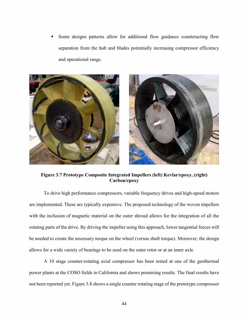
44
Some designs patterns allow for additional flow guidance counteracting flow
separation from the hub and blades potentially increasing compressor efficiency
and operational range.
To drive high performance compressors, variable frequency drives and high-speed motors
are implemented. These are typically expensive. The proposed technology of the woven impellers
with the inclusion of magnetic material on the outer shroud allows for the integration of all the
rotating parts of the drive. By driving the impeller using this approach, lower tangential forces will
be needed to create the necessary torque on the wheel (versus shaft torque). Moreover, the design
allows for a wide variety of bearings to be used on the outer rotor or at an inner axle.
A 10 stage counter-rotating axial compressor has been tested at one of the geothermal
power plants at the COSO fields in California and shows promising results. The final results have
not been reported yet. Figure 3.8 shows a single counter rotating stage of the prototype compressor
Figure 3.7 Prototype Composite Integrated Impellers (left) Kevlar/epoxy, (right)
Carbon/epoxy

45
ready for testing. This 10 stage compressor is indented to replace a steam ejector system at this
single flash geothermal power plant. Figure 3.10 shows a geothermal power plant layout, upgraded
to a multi-stage axial compressor and its possible benefits.
A 10 stage counter-rotating axial compressor (Figure 3.9) has been tested at one of the
geothermal power plants at the COSO fields in California and shows promising results. The final
results have not been reported yet. This 10 stage compressor is indented to replace a steam ejector
system at this single flash geothermal power plant. Figure 3.10 shows a geothermal power plant
layout, upgraded to a multi-stage axial compressor and its possible benefits.
Since the NCG are so harmful, near complete removal is crucial. Most of the current flash
geothermal power plants employ steam jet ejectors which have a low efficiency and consume a
much of the well steam. The proposed technology could be used to upgrade existing GPPs and
Figure 3.8 Single stage counter rotating setup of the
prototype compressor
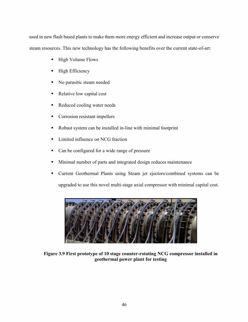
46
used in new flash based plants to make them more energy efficient and increase output or conserve
steam resources. This new technology has the following benefits over the current state-of-art:
High Volume Flows
High Efficiency
No parasitic steam needed
Relative low capital cost
Reduced cooling water needs
Corrosion resistant impellers
Robust system can be installed in-line with minimal footprint
Limited influence on NCG fraction
Can be configured for a wide range of pressure
Minimal number of parts and integrated design reduces maintenance
Current Geothermal Plants using Steam jet ejectors/combined systems can be
upgraded to use this novel multi-stage axial compressor with minimal capital cost.
Figure 3.9 First prototype of 10 stage counter-rotating NCG compressor installed in
geothermal power plant for testing

47
Operational and economic analyses of the complete system of the flash geothermal power
plant should be performed for each projected case to determine the specific economic benefits of
this new technology. This could be the extension and continuation to this study.
Figure 3.10 Geothermal power plant upgraded to a multi-stage axial compressor for
NCG removal

48
CHAPTER 4: STRUCTURAL ANALYSIS OF COMPOSITE
WOUND IMPELLER
This chapter describes the structural analysis procedure using finite element methods for
the wound axial impeller that can be used in a multistage counter rotating axial compressor for
compressing water vapor (R718). Three different fiber types were chosen as suitable materials for
this study (Kevlar-49, S-glass & Carbon fiber) with a standard epoxy resin for the composite
matrix. Through means of FEA (Finite Element Analysis) method; stress, displacement and
vibration analysis procedure is developed to assess the maximum stress, change in dimensions and
natural frequencies of these impellers under constant operating conditions. The finite element
modeling was performed on commercially available software Abaqus. The modeling technique is
explained in detail with regards to static structural and dynamic analysis of the impellers.
Operating stresses, maximum shroud deflections, modal frequencies and effect of centrifugal
stiffening is calculated and discussed in detail along with Campbell plots for each fiber material
type. The study provides critical details about the structural behavior of the impellers and aims to
provide a methodology to the compressor designer to support his decision in choosing the type of
impeller and designing the housing.
4.1 COMPOSITE WOUND IMPELLER
Different impeller designs have been investigated and shown promising results to be used
in a high speed counter rotating axial compressor for compressing water vapor [13] [37]. In this
analysis; one of the patterns (8-B), with curved blades and a Flow Hub/blade tip ratio of 0.54 is
structurally investigated with the help of FEA for three different fiber types:

49
Kevlar-49
Carbon or graphite fiber
S-Glass
Table 4.1. These material properties are used in the numerical model. The three fibers were
chosen because of their high specific strength (ratio of tenacity to density), (Figure 4.2) and history
of being used for filament winding with ease. These fiber composites are also highly resistant to
corrosion in the presence of water vapor. The resulting impellers from this novel filament winding
technique [37] [38] are low cost and easy to manufacture compared to manufacturing and mounting
of titanium alloy or separately manufactured composite blades. These composite impellers can be
much stronger and lighter than Titanium alloy blade impellers.
Figure 4.1 Kevlar wound composite impeller with its dimensions
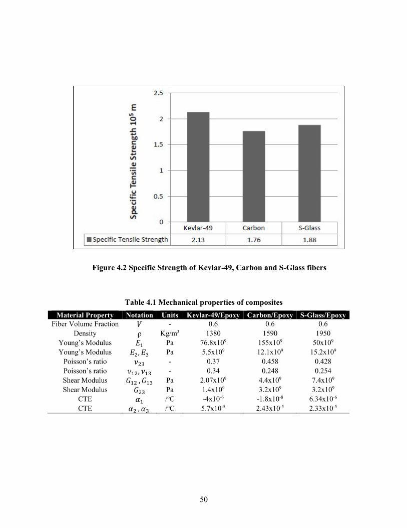
50
Table 4.1 Mechanical properties of composites
Material Property Notation Units Kevlar-49/Epoxy Carbon/Epoxy S-Glass/Epoxy
Fiber Volume Fraction 𝑉 - 0.6 0.6 0.6
Density ρ Kg/m3 1380 1590 1950
Young’s Modulus 𝐸1 Pa 76.8x10⁹ 155x109 50x109
Young’s Modulus 𝐸2, 𝐸3 Pa 5.5x10⁹ 12.1x10⁹ 15.2x10⁹
Poisson’s ratio 𝜈23 - 0.37 0.458 0.428
Poisson’s ratio 𝜈12, 𝜈13 - 0.34 0.248 0.254
Shear Modulus 𝐺12 , 𝐺13 Pa 2.07x10⁹ 4.4x10⁹ 7.4x10⁹
Shear Modulus 𝐺23 Pa 1.4x10⁹ 3.2x10⁹ 3.2x10⁹
CTE 𝛼1 /oC -4x10⁻⁶ -1.8x10⁻⁸ 6.34x10⁻⁶
CTE 𝛼2 , 𝛼3 /oC 5.7x10⁻⁵ 2.43x10⁻⁵ 2.33x10⁻⁵
Figure 4.2 Specific Strength of Kevlar-49, Carbon and S-Glass fibers

51
4.2 NUMERICAL (FEA) MODEL
A 3-Dimensional computer aided design (CAD) model of the impeller was generated in
NX 7.5 software which was exported to Finite Element Method software (Abaqus 6.9) and a
numerical model of the entire impeller was prepared. Since the properties of the composite are
different in all the three perpendicular directions (orthotropic) the model was sectioned into 35
different parts (Outer shroud, flow hub, inner central hub and 8x4 blade sections) each with their
own material coordinate system. Figure 4.3 shows the different sections of the impeller with their
own material co-ordinate system.
Each of the 35 parts is modeled as a single laminated ply with a thickness of 2.8mm and
having all straight (0o) fibers. The outer shroud, flow hub and the inner central hub have straight
Figure 4.3 Geometrical model of the impeller showing the material co-ordinate systems

52
fibers running in parallel to each other along the circumference whereas the blades have straight
fibers running parallel to each other along the blade length. Figure 4.1 gives the dimensions of the
impeller. The inlet blade angle (β1) is 30o and the outlet blade angle (β2) is 90o
4.3 FEM MESH
A free meshing technique was employed with Abaqus default algorithm. A standard 4-
node linear tetrahedron element, C3D4 was used.
Figure 4.4 shows a C3D4 element. Quad and Hex mesh could not be used because of
complex geometry within free meshing, the problematic areas being the intersection of blades and
Figure 4.4 C3D4 element

53
the outer shroud. Mapped tri meshing on bounding faces was employed where appropriate.
Curvature control was turned on with maximum deviation factor (h/L) of 0.1. The numerical (FEA)
model was composed of 81,542 nodes and 249,696 linear tetrahedral elements of type C3D4.
Because of the complex geometry and thin thickness, a very fine mesh size was chosen and further
refined till convergence was obtained. The numerical model (meshed) is shown in Figure 4.5.
4.4 MESH CONVERGENCE
Convergence criterion is important and should be considered before evaluating results. A
stress based convergence criterion is employed for this model. The stabilization of stress
components S11 (along the fiber direction) and S33 (perpendicular to fiber direction) for the
Kevlar-49/Epoxy model is considered as the convergence criterion. The mesh density is increased
Figure 4.5 Meshed model showing all the coordinate systems

54
in a step by step process and the stress value noted. Figure 4.6 shows the results of the convergence
analysis. It is clear that the convergence is obtained after about 110,000 elements. Because of the
complex geometry and thin thickness, a very fine mesh size was chosen and further refined to
about 250,000 elements.
4.5 BOUNDARY CONDITIONS AND LOADING
All nodes at the central hub which connect to a shaft were constrained such that
U3=UR1=UR2=0, where U denotes the displacements of the nodes in global coordinate system
and R denotes the rotational degree of freedom. This is show in Figure 4.7. Since R-718 cycle
works under very low pressures, aerodynamic forces are neglected. Steady state centrifugal load
is applied to the entire model. Thermal load in the form of operating temperature, 90oC is also
applied.
Figure 4.6 Mesh Convergence

55
4.6 FEA SOLVER
A Direct Implicit equation solver with Full Newton solution technique is used for the
analysis. Non linear geometric effects (NLGEOM) were turned on to enable strain measures to
account for higher order terms. Following are some of the assumptions for the numerical model:
Only steady state centrifugal forces are considered on the impeller
The aerodynamics forces due to fluid and the angular acceleration effects are
neglected
The impeller is modeled as an orthotropic elastic material
U3=UR1=UR2=0
Figure 4.7 Boundary Conditions

56
A constant temperature field of 90oC is assumed for the model (operating
temperature)
For modal analysis, free vibrations are assumed with no damping
The stress-strain relations for a laminated composite modeled as orthotropic linear elastic
material can be defined by giving the nine independent elastic stiffness parameters, as functions
of temperature and other predefined fields, if necessary [39] [40]
23
13
12
33
22
11
23
13
12
33
22
11
2323
1313
1212
3333
22332222
113311221111
23
13
12
33
22
11
0
00
000
000
000
elD
D
Dsym
D
D
DD
DDD
(1)
where elD is known as the stiffness matrix. The FEA software requires these nine
independent constants as inputs for each composite material.
The stiffness matrix elD is defined as:
𝐷1111 = 𝐸1 (1 − 𝜈23 𝜈32)𝜆,
(2)
𝐷2222 = 𝐸2 (1 − 𝜈13 𝜈31)𝜆,
(3)
𝐷3333 = 𝐸3(1 − 𝜈12𝜈21)𝜆 ,
(4)
𝐷1122 = 𝐸1 (𝜈21 + 𝜈31𝜈23)𝜆 = 𝐸2 (𝜈12 + 𝜈32𝜈13)𝜆,
𝐷1133 = 𝐸1 (𝜈31 + 𝜈21𝜈32)𝜆 = 𝐸3(𝜈13 + 𝜈12𝜈23)𝜆,
(5)
(6)
𝐷2233 = 𝐸2 (𝜈32 + 𝜈12𝜈31)𝜆 = 𝐸3(𝜈23 + 𝜈21𝜈13)𝜆,
(7)
𝐷1212 = 𝐺12,
(8)
𝐷1313 = 𝐺13,
(9)

57
𝐷2323 = 𝐺23,
(10)
where
13322113313223212 211
1
(11)
A short Matlab code was written to generate these constants for the three composites. The
material properties (Table 4.1) were a user input.
4.7 STATIC STRESS ANALYSIS AND RESULTS
For a linear static structural analysis, the displacements {x} are solved for in the matrix
equation given by the Hooke’s Law:
}{}{ FxK (12)
Static analysis assumptions:
[K] is constant
Small deflection theory is used
Some nonlinear boundary conditions may be included
{F} is statically applied and no time-varying forces are considered
No inertial effects (mass, damping) are included
The static analysis in Abaqus was done in steps. In each subsequent step the rotational
speed was increased by 1000 rotations per minute (rpm). The rpm was increased till the composite
failed. The operating conditions for the impellers are around 10000rpm with a 90oC temperature.
Both centrifugal and thermal effects are taken into account for displacement and stress analysis.
Maximum stress failure criterion for plane-stress has been used for this analysis which states that
[41]:
A fiber-reinforced composite material in a general state of stress will fail when:

58
Either, the maximum stress in the fiber direction equals the maximum stress in a uniaxial
specimen of the same material loaded in the fiber direction when it fails; or, the maximum stress
perpendicular to the fiber direction equals the maximum stress in a uniaxial specimen of the same
material loaded perpendicular to the fiber direction when it fails; or, the maximum shear stress in
the 1-2 plane equals the maximum shear stress in a specimen of the same material loaded in shear
in the 1-2 plane when it fails.
TC
111 (13)
TC
222
(14)
F
1212 (15)
The blade tip clearance or the shroud-housing clearance; in this case, should be kept as low
as possible for higher efficiency and higher pressure ratios in an axial compressor. Figure 4.9
shows the maximum displacement of nodes on the outer edge of the shroud. The figure shows both
the U (displacement) magnitude and the U radial for the impellers. Carbon/Epoxy impeller has the
least U radial due to centrifugal forces (10,000 rpm) and temperature field (90oC) combined. S-
Glass/Epoxy has almost three times the U radial as Carbon/Epoxy. Knowing the correct U radial

59
values for the impeller at operating speed is very crucial in the design process of the compressor
and the housing.
Figure 4.9 Maximum nodal displacements under operating conditions
Figure 4.8 Maximum Stresses for different composites at operating conditions

60
Figure 4.8 gives the maximum values for stresses at 10,000 rpm for the impellers. Kevlar-
49/Epoxy impeller has the maximum 1 or S11 (stress along the direction of fiber) and S-
Glass/Epoxy impeller has the maximum 2 or S33 (stress perpendicular to direction of fiber).
Figure 4.10 gives the normalized value of the maximum stresses at 10,000 with respect to
the failure stresses for each material. Carbon/Epoxy is the strongest and S-Glass/Epoxy is the
weakest with a 2 or S33 of 0.92 suggesting a very low factor of safety. For all the three impellers
the failure mode was T
22 . For Kevlar-49/Epoxy impeller the elements exceed failure stress
at 12,000 rpm. The carbon/Epoxy impeller shows sign of failure starting at 13,000 rpm. The S-
Glass/Epoxy impeller starts to fail around 12,000 rpm. These results also show that the flow hub
is the weakest part in the design and should be strengthened to withstand higher centrifugal forces
Figure 4.10 Maximum Normalized stresses (normalized to failure stress)
for different composites at operating conditions

61
at high speeds. Figure 4.11 shows the failure zones for the three impellers at the corresponding
roational speeds. The red zones in the figure are the maximum limit of T
2 for each composite.
The results from the static stress analysis can further be used to estimate the fatigue life of
these novel wound composite impellers as show in previous preliminary studies [42]

62
Figure 4.11 Stress plots. Red color indicates failure zones

63
4.8 DYNAMIC ANALYSIS AND RESULTS
Governing equation for Modal analysis [43],
}{}{}{}{ FuKuCuM , (16)
Assuming free vibrations and ignoring damping:
}0{}{}{ uKuM (17)
Now assuming harmonic motion:
)sin(}{}{ iii tu (18)
)cos(}{}{ iiii tu (19)
)sin(}{}{ 2
iiii tu (20)
Substituting the above harmonic relations in the equation above and simplifying
(
2
i M + K ) i}{ = }0{ (21)
This equality is satisfied if i}{ =0 (trivial, implies no vibration) or if
}0{)det( 2 MK i (22)
This is an Eigen vector problem which may be solved for up to n eigenvalues, 2
i and n
eigenvectors, i}{ , where n is the number of DOF. Since the equation has one more unknown than
equations; therefore, an additional equation is provided by mode shape normalization. Mode
shapes can be normalized either to the mass matrix 1}{}{ i
T
i M or to unity, where the largest
component of the vector i}{ is set to 1. In this study, the FEA software tool Abaqus displays
results normalized to the mass matrix. Because of the normalization, only the shape of the DOF
solution has real meaning. In order to find the real displacements and stresses additional
experimental investigations have to be carried out like using strain gages on the impeller to get the
actual displacements and stresses. The free vibration with pre-stress analysis is solved, including
the [S] term:
(2
i M + SK ) i}{ = }0{ (23)

64
where the [S] matrix is the global geometric stiffness matrix representing the “Centrifugal
Stiffening effect” which depends on the initial stress distribution.
Fig. 13 shows the first 10 modes for Kevlar-49/Epoxy impeller. Since the FEM solver
normalizes the mode shapes to the mass matrix, all three impellers (Kevlar-49/Epoxy,
Carbon/Epoxy, S-Glass/Epoxy) have the same mode shapes.
Figure 4.12 First 10 Mode shapes for a Kevlar-49/Epoxy impeller with no centrifugal
loading. The contours denote the U magnitude.

65
Table 4.2 Natural Frequencies with and without the effect of centrifugal loading
(10,000 RPM)
Kevlar-49/Epoxy
Mode Natural frequency Natural frequency due to CS effects
Change in frequency due to CS effects
1.0 389.9 392.7 0.7
2.0 577.8 603.1 4.4
3.0 578.1 603.5 4.4
4.0 667.4 685.3 2.7
5.0 838.0 916.4 9.4
6.0 838.7 917.1 9.3
7.0 922.9 1090.8 18.2
8.0 948.6 1093.3 15.3
9.0 954.1 1099.8 15.3
10.0 1006.4 1112.4 10.5
Carbon/Epoxy
Mode Natural frequency Natural frequency due to CS effects
Change in frequency due to CS effects
1.0 475.5 476.4 0.5
2.0 705.3 707.4 2.8
3.0 705.8 707.9 2.8
4.0 816.9 820.0 1.8
5.0 985.0 990.6 7.0
6.0 985.9 991.6 6.9
7.0 1024.7 1031.1 15.0
8.0 1054.8 1061.3 13.5
9.0 1062.3 1068.8 13.0
10.0 1125.2 1131.6 6.8
S-glass/Epoxy
Mode Natural frequency Natural frequency due to CS effects
Change in frequency due to CS effects
1.0 381.6 386.8 1.4
2.0 588.4 613.5 4.3
3.0 589.3 614.1 4.2
4.0 660.3 682.2 3.3
5.0 691.6 825.6 19.4
6.0 708.2 826.0 16.6
7.0 719.2 849.7 18.1
8.0 727.3 854.3 17.5
9.0 728.5 887.7 21.8
10.0 755.7 894.2 18.3
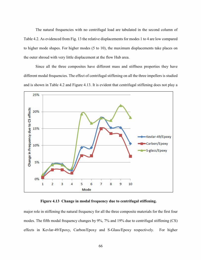
66
The natural frequencies with no centrifugal load are tabulated in the second column of
Table 4.2. As evidenced from Fig. 13 the relative displacements for modes 1 to 4 are low compared
to higher mode shapes. For higher modes (5 to 10), the maximum displacements take places on
the outer shroud with very little displacement at the flow Hub area.
Since all the three composites have different mass and stiffness properties they have
different modal frequencies. The effect of centrifugal stiffening on all the three impellers is studied
and is shown in Table 4.2 and Figure 4.13. It is evident that centrifugal stiffening does not play a
major role in stiffening the natural frequency for all the three composite materials for the first four
modes. The fifth modal frequency changes by 9%, 7% and 19% due to centrifugal stiffening (CS)
effects in Kevlar-49/Epoxy, Carbon/Epoxy and S-Glass/Epoxy respectively. For higher
Figure 4.13 Change in modal frequency due to centrifugal stiffening.

67
frequencies (sixth mode onwards) the effects of centrifugal stiffening are quite pronounced highest
being in S-glass followed by Kevlar-49 and Carbon
The Campbell diagram is one of the most important tools for understanding the
dynamic behavior of a rotating machine. It basically consists of a plot of the natural
frequencies of the system as functions of the spin speed on which the frequencies of the
forcing excitation functions are superimposed. Although based on complete linearity, the
Campbell diagram of the linearized model can yield much important information concerning
a non- linear rotating system. A Campbell diagram or a Campbell plot is an overall (or bird’s-
eye) view of the regional vibration excitation that can occur on an operating system [44]. The
Campbell plots for the present analysis were generated for the first 10 undamped modal
frequencies at different operating speeds from Abaqus. For a multistage axial compressor using a
tight axial gap between the two adjacent blade rows is considered beneficial from an efficiency
viewpoint [45]. A tight gap also means high chances of blade vibration due to the periodic pressure
force generated by the close presence of the adjacent blade row. This makes it important to
consider not only the 1x synchronous frequency but also higher frequencies.
The Campbell plots for the three impellers are shown in Fig. 15, 16 and 17. The red line
represents the operating speed (10,000 rpm) and the black dashed line represents the rotor speed
harmonics. In case of Carbon/Epoxy impeller the fifth rotor harmonic (833.33 Hz) is very close to
the impellers forth modal frequency (831.62 Hz) with difference being only 1.71 Hz. Similarly for
S-Glass/Epoxy impeller the fifth (825.57Hz) and sixth (825.95Hz) modal frequencies are close to
the fifth rotor harmonic (833.33Hz). Kevlar-49/Epoxy impeller is safe for operation at 10,000 rpm.

68
Figure 4.14 Campbell Plot for Kevlar-49/Epoxy impeller
0
200
400
600
800
1000
1200
1400
1600
1800
0 2000 4000 6000 8000 10000 12000 14000 16000
Fre
qu
ency
(H
z)
RPM
Mode 1
Mode 2
Mode 3
Mode 4
Mode 5
Mode 6
Mode 7
Mode 8
Mode 9
Mode 10
1XSynch
2x
3x
4x
5x

69
0
200
400
600
800
1000
1200
1400
1600
1800
0 2000 4000 6000 8000 10000 12000 14000 16000
Fre
qu
ency
(H
z)
RPM
Mode 1
Mode 2
Mode 3
Mode 4
Mode 5
Mode 6
Mode 7
Mode 8
Mode 9
Mode 10
1XSynch
2x
3x
4x
5x
Figure 4.15 Campbell Plot for Carbon/Epoxy impeller

70
0
200
400
600
800
1000
1200
1400
1600
1800
0 2000 4000 6000 8000 10000 12000 14000 16000
Fre
qu
ency
(H
z)
RPM
Mode 1
Mode 2
Mode 3
Mode 4
Mode 5
Mode 6
Mode 7
Mode 8
Mode 9
Mode 10
1XSynch
2x
3x
4x
5x
Figure 4.16 Campbell Plot for S-Glass/Epoxy impeller

71
3-D numerical model of the impeller was generated. Due to the complex geometry and
curved blades the entire model had to be broken up into 35 parts each with its own material co-
ordinate system. The impellers were modeled as orthotropic elastic and material properties were
input into the FEA software. Progressive failure analysis was not performed and Max stress failure
criterion was used to judge the onset of failure
From the static analysis Carbon/Epoxy impeller seems superior in comparison to Kevlar-
49/Epoxy and S-Glass/Epoxy impeller. Carbon/Epoxy impeller fails at 13,000 rpm compared to
12,000 rpm for other two fiber wound impellers. Carbon /Epoxy impeller also has the minimum
change in U radial (0.512 mm) although Kevlar-49/Epoxy is close (0.66 mm). S-Glass/Epoxy
because of its low tensile modulus and high density has a comparatively high U radial (1.76 mm).
Static stress analysis results show that the impeller can be further strengthened if the flow
hub/blade region is strengthened. Effect of Centrifugal stiffening on the natural frequency cannot
be neglected especially at modes greater than 4. From the Campbell plots, Kevlar-49/Epoxy does
not seem to encounter any problematic frequencies at operating conditions and is safe for operation
at 10,000 rpm. Further harmonic analysis needs to be done to check the Carbon/Epoxy and S-
glass/Epoxy impellers behavior at the fifth rotor harmonic 833.33 Hz before they can be used in
operation.
Kevlar has excellent toughness properties but not as strong as carbon fiber. Carbon on the
other hand is brittle and would shatter and fail catastrophically. S-Glass is the cheapest option
among the three fibers. The study has provided critical details about the structural behavior of the
impeller; therefore, the methodology and the results of this study may be used to guide and support
compressor designers in their decision to choose the type of impeller and to design the housing.

72
CHAPTER 5: STRUCTURAL OPTIMIZATION OF THE
INTEGRATED COMPOSITE WOUND AXIAL IMPELLER
The previous chapter had focused on the structural analysis of the original design. This
design had a central power transmitting shaft run by a motor as a part of the axial compressor. This
chapter focuses on structural analysis and design optimization of an integrated rotor. This design
has permanent magnets on the outer shroud of the impeller as a part of the rotor (see chapter 2,
Figure 2.8). The magnet element can be baked along with the fiber wound impeller when it is
undergoing resin curing. The manufacturing details of these integrated impellers would not be
presented in this research work.
This integrated rotor can be used for either water as a refrigerant or for non-condensable
gas removal at a geothermal power plant. The research utilizes the finding from the last chapter
[46] and focuses on the effect of each individual parameter (blade thickness, shroud thickness,
location on magnets etc.) on the impellers strength and mechanical performance. Finally, all the
parameters are considered together and a Design of Experiment type study is conducted for final
design optimization.
5.1 INTRODUCTION TO ANSYS
ANSYS is a well-established, well-verified, and commercially available structural finite
element analysis software package that has been used widely in industry and academia for over 40
years. Over that time it has advanced rapidly to include state-of-the-art physics modeling
capabilities that include structural mechanics, fluid dynamics, explicit dynamics, and
electromagnetics. Additionally, ANSYS has acquired or developed a number of specific structural

73
mechanics modules to handle rigid body dynamics, composite materials, fatigue, and acoustics
analysis.
With its version 12.0 release, ANSYS introduced a newly reengineered form of its
workflow technology tool called the ANSYS Workbench Platform. Workbench is a framework
which hosts a large fraction of ANSYS software products and components in a project schematic
diagram. The project geometry, physics simulation tools, boundary conditions, engineering data
and solution results are all managed from a single page. Geometry, material properties and model
parameters may be reused in other analyses simply by dragging and dropping that information into
a new analysis box.
Workbench features include bi-directional, parametric links to all major CAD systems,
geometry modeling/repair/simplification using ANSYS DesignModeler, highly-automated
meshing, contact detection, and project level parameter variations, to name a few. Parametric
variations include CAD geometry dimensions, material properties, boundary conditions, and
derived results. The ability to perform parametric variations at a project level page is powerful
when considering something as complex as the design and optimization of a turbomachinery blade.
Changes may be made to geometry, material properties, mesh density, boundary conditions,
element types, etc, and the entire suite of physics solutions that have been linked to the blade model
is updated automatically to show the changes in the calculated results. ANSYS DesignModeler,
available within the Workbench Platform, is a geometry modeling tool that approaches the
sophistication of a high-end CAD package such as SolidWorks or Unigraphics. DesignModeler is
a feature based solid modeler which can be used to create a parametric geometry from scratch or
prepare an existing CAD geometry for analysis. Its capabilities uniquely include features and tools
specifically intended to prepare a geometry model for analysis. Therefore, if a model has been

74
imported from a CAD system, it can be appropriately de-featured of extraneous geometry not
necessary for an analysis, and conversely, features may be added that aid in applying loads and
boundary conditions.
Before ANSYS Workbench was available, modeling an impeller in ANSYS Classic (the
conventional ANSYS GUI and solver), would have been time consuming and frustrating. The
reasons for this are many. The amount of information needed to define an impeller in three-
dimensions is non-trivial. Complex geometry inputs and subsequent surface descriptions,
anisotropic material property definitions, and material layup schedules that vary for different blade
regions all combine to make modeling a blade in any detail book-keeping intensive and very time
consuming, with little flexibility in the end to modify parameters for optimization studies.
Although ANSYS Classic includes composite material definition capability, the interface for
describing complex.
With the new add-on module for Workbench version 14.0 and later, defining and
optimization of composite layup has become manageable and easy. Complex impeller geometries
can be imported into ANSYS Workbench and material definition assigned in 3-D. The whole
process of optimization has also been streamlined. Although the current research focusses only on
the structural optimization (because of low fluid forces under operating conditions of low
pressure), fluid-structure optimization is possible. The typical steps involved in the current analysis
using ANSYS WB and ANSYS composite pre-post are summarized in Figure 5.1

75
CAD model designed in Seimens NX software
CAD model designed in Seimens NX software
Import the model in ANSYS WB and edit the geometry in Design Modeler if
needed
Import the model in ANSYS WB and edit the geometry in Design Modeler if
needed
Define the composite layup, fiber orientation and orthotropic mechanical
properties within ANSYS ACP
Define the composite layup, fiber orientation and orthotropic mechanical
properties within ANSYS ACP
Mesh the shell model of the Impeller in ANSYS Mechanical
Mesh the shell model of the Impeller in ANSYS Mechanical
Define the boundary conditions for the setup and select the analysis type eg:
Static Structural and Modal
Define the boundary conditions for the setup and select the analysis type eg:
Static Structural and Modal
Post process the composite results in ANSYS ACP post
Post process the composite results in ANSYS ACP post
Design Optimization Design Optimization
Figure 5.1 Flowchart summarizing the key analysis steps with ANSYS WB

76
5.2 FINITE ELEMENT MODEL SETUP
The composite impeller 3-D shell model is generated in Siemens NX 7.5. Impellers shape
8-B has been used for analysis as in Chapter 4. The new design does not have an inner flow hub,
as it was found out to be a structurally weak element in the design. Each individual blade is
modelled as a composite layup with fibers along the direction of the blade. The shroud is modeled
as a separate composite layer. The blades and the shroud are “stitched” in the 3-D model in NX
which is same as assuming a perfect bond between the blade and the shroud. The model does not
simulate a continuous single or multiple strands of fiber wounds which generate continuous fibers
making the blade and the shroud. Figure 5.2 shows the actual impeller design wound from Kevlar-
49 and epoxy along with the meshed 3-D shell model of the impeller as seen in ANSYS ACP.
Figure 5.2 Right: Actual woven wheel impeller, Left: Meshed model of the woven wheel in
ANSYS ACP
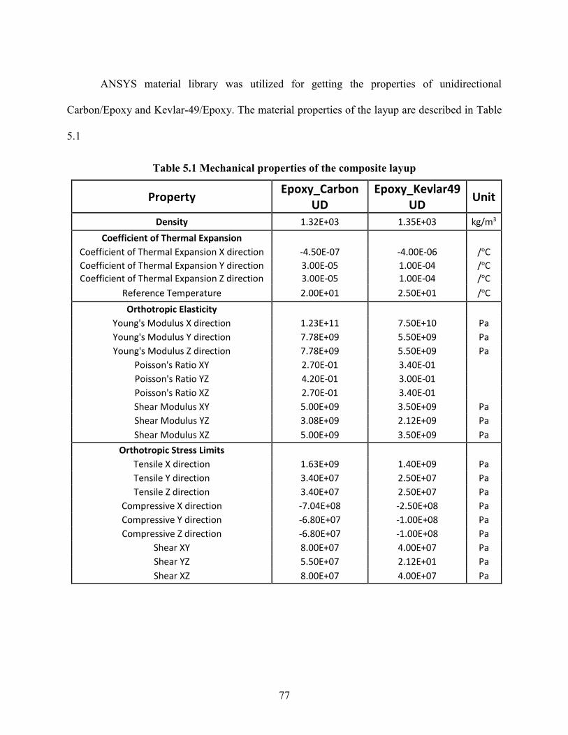
77
ANSYS material library was utilized for getting the properties of unidirectional
Carbon/Epoxy and Kevlar-49/Epoxy. The material properties of the layup are described in Table
5.1
Table 5.1 Mechanical properties of the composite layup
Property Epoxy_Carbon
UD Epoxy_Kevlar49
UD Unit
Density 1.32E+03 1.35E+03 kg/m3
Coefficient of Thermal Expansion
Coefficient of Thermal Expansion X direction -4.50E-07 -4.00E-06 /oC
Coefficient of Thermal Expansion Y direction 3.00E-05 1.00E-04 /oC
Coefficient of Thermal Expansion Z direction 3.00E-05 1.00E-04 /oC
Reference Temperature 2.00E+01 2.50E+01 /oC
Orthotropic Elasticity
Young's Modulus X direction 1.23E+11 7.50E+10 Pa
Young's Modulus Y direction 7.78E+09 5.50E+09 Pa
Young's Modulus Z direction 7.78E+09 5.50E+09 Pa
Poisson's Ratio XY 2.70E-01 3.40E-01
Poisson's Ratio YZ 4.20E-01 3.00E-01
Poisson's Ratio XZ 2.70E-01 3.40E-01
Shear Modulus XY 5.00E+09 3.50E+09 Pa
Shear Modulus YZ 3.08E+09 2.12E+09 Pa
Shear Modulus XZ 5.00E+09 3.50E+09 Pa
Orthotropic Stress Limits
Tensile X direction 1.63E+09 1.40E+09 Pa
Tensile Y direction 3.40E+07 2.50E+07 Pa
Tensile Z direction 3.40E+07 2.50E+07 Pa
Compressive X direction -7.04E+08 -2.50E+08 Pa
Compressive Y direction -6.80E+07 -1.00E+08 Pa
Compressive Z direction -6.80E+07 -1.00E+08 Pa
Shear XY 8.00E+07 4.00E+07 Pa
Shear YZ 5.50E+07 2.12E+01 Pa
Shear XZ 8.00E+07 4.00E+07 Pa

78
The failure criterion used for the analysis was Tsai Hill.
The Tsai Hill is a quadratic stress-based criterion applied to individual composite ply. The
criterion evaluates failure based on combination of stress components designed to take into
consideration a multi-axial stress state and how the combination of different stress components
affect the failure initiation in a composite ply.
𝜎112
𝑆112 −
𝜎11𝜎22
𝑆112 +
𝜎222
𝑆222 +
𝜎122
𝑆122 ≥ 1.0
The coefficients 𝑆𝑖𝑗 of the Tsai-Hill criterion are computer as follows:
𝑆11+ Value of σ11 at longitudinal tensile failure
𝑆11− Value of σ11 at longitudinal compressive failure
𝑆22+ Value of σ22 at longitudinal tensile failure
𝑆22− Value of σ22 at longitudinal compressive failure
𝑆12 Value of σ12 at longitudinal tensile failure
If σ11 ≥ 0, then 𝑆11 = 𝑆11+
If σ11 < 0, then 𝑆11 = 𝑆11−
If σ22 ≥ 0, then 𝑆22 = 𝑆22+
If σ22 < 0, then 𝑆22 = 𝑆22−

79
5.3 EFFECT OF FIBER TYPE
Previous research [46] and analysis conducted suggested that using glass fiber was not
viable because of its low specific strength and high shroud deflections. Three fiber types are
compared here: carbon fiber, Kevlar-49 fiber and a hybrid (½ carbon fiber and ½ Kevlar fiber by
volume). A hybrid fiber was considered keeping in mind the high strength of carbon and high
toughness of Kevlar. The results summarized in Table 5.2, show that an impeller made up of only
Kevlar fiber and epoxy fails structurally at 10,000 rpm, hybrid impeller at 11,000 rpm and carbon
fiber/epoxy impeller at 12,000 rpm. Carbon fiber/epoxy impeller has the lower deflections at its
highest rotational speed. Since carbon fiber/epoxy impeller is the strongest with least amount of
deflections, it’s considered as the base material for design.
Table 5.2 Effect of fiber type on the structural strength of the impeller
Carbon4 Hybrid4 Kevlar4
Failure Rpm 12000 11000 Below 10000
Max radial deflection (Shroud), mm 0.56 0.71 -
Max out of plane deflection (Z), mm 0.60 0.76 -
Max total blade deflection, mm 1.87 2.35 -
5.4 EFFECT OF ADDITIONAL SHROUD
Since the most common failure zone/area was the intersection of the blades with the inner
shroud, effect of further strengthening the shroud is studied. Two design variations are considered.
The first (Carbon4S4) is the base design with an additional layer of shrouding making the total
shroud thickness as 2.8+2.8 = 5.6 mm. The second design variation has an additional 2.8 mm
woven ply instead of straight fibers (Carbon4SW4).

80
Table 5.3 Effect of additional shroud on the structural strength of the impeller
Carbon4 Carbon4S4 Carbon4SW4
Max radial deflection (Shroud), mm 0.56 0.38 0.465
Max out of plane deflection (Z), mm 0.60 0.54 0.54
Max total blade deflection, mm 1.87 1.71 1.69
Failure Rpm 12000 13000 13000
As can be seen from Table 5.3 and Figure 5.3, an additional shroud increases the overall
strength of the impeller. Failure speed is increased from 12,000 rpm to 13,000 rpm. Overall blade
and shroud deflections are also decreased due to the additional shroud. Figure 5.3 also shows that
an additional shroud of straight fibers is more effective than an additional shroud of woven ply.
This is easy to incorporate into manufacturing. After the complete impeller is wound, additional
fiber could be wound around and the thickness can be controlled.

81
5.5 EFFECT OF NUMBER OF PLIES
Keeping the total blade thickness fixed, the number of plies were varied. For a 4 ply
impeller with total blade thickness of 2.8mm, each ply would be 0.7 mm thick. Similarly an 8 ply
design would have 0.35 mm thick plies and so on. In reality larger the number of plies for the same
thickness better the structural strength of the composite layer. But, since the composite pre-post
solver treats the layer as quasi 3-D and perfect bonding is assumed between the layers, changing
the number of plies for the same thickness (and material) did not show any different results.
Impeller(Carbon4)
Impeller withadditional shroud
(Carbon4S4)
Impeller withwoven prepeg(Carbon4SW4)
Max. radial deflection (Shroud) 0.56 0.38 0.465
Max. out of plane deflection (Z) 0.6 0.54 0.54
Max. total blade deformation 1.87 1.71 1.695
0
0.2
0.4
0.6
0.8
1
1.2
1.4
1.6
1.8
2
Def
lect
ion
(m
m)
Effect of additional shroud
Figure 5.3 Effect of additional shrouding on the deformations of the impeller

82
Table 5.4 Effect of number of plies (same total thickness) on the structural behavior of
impeller
Carbon4 Carbon8 Carbon12
Max radial deflection (Shroud), mm 0.56 0.56 0.56
Max out of plane deflection (Z), mm 0.60 0.60 0.60
Max total blade deflection, mm 1.87 1.87 1.87
Failure Rpm 12000 12000 12000
5.6 EFFECT OF BLADE THICKNESS
Although the blade thickness is usually governed by the aerodynamic design of the
impeller, it was found out from analysis that effect of blade thickness cannot be studied alone. It
was connected to the additional shroud thickness and the magnet location. Thin blades meant very
high deformations or blades fanning out. Thick blades means more weight, material and not
aerodynamically preferred. Within the giver margin of blade thickness, the goal was to minimize
the blade thickness.
5.7 EFFECT OF BLADE TWIST ANGLE
The actual blade angle of the impeller is governed mostly by its application and
aerodynamic requirements. Still sometime there is as leeway in design and the design has a fair
margin. In such cases it is important to know how the blade twist angle effects the overall structural
behavior of the impeller. To get a detailed understanding of how the blade twist angles effect the
structural strength of the impeller, 8 designs were compared. The lower end of the design had 4o
blade twist angle (least flow obstruction) and highest with 32o (highest flow obstruction). The
blades in this analysis were straight with no curvature along the flow axis. Figure 5.4 shows the
blade twist variation for a meshed impeller.

83
Blade twist angle 4o Blade twist angle 16o Blade twist angle 28o
Figure 5.4 Meshed impeller for various blade twist angles
Table 5.5 summarizes the blade and shroud deflections along with the failure rpm as a
function of the blade twist angle. The impeller strength seems to increase as the blade twist angle
is increased. Since the analysis conceded rpm increments in 1000, a detailed analysis has to be
conducted to exactly study the relationship. Figure 5.5 shows that the max blade deflection
decreases as the blade twist angle is increased. Figure 5.6 shows the impeller deflections against
the blade twist angle. The max radial deflection of the shroud peaks at 12o and then decreases. The
out of plane blade deflection peaks at 28o. At blade twist angle of 14o both the plots intersect giving
the minimum for both. This shows that the design is parameter sensitive and could be optimized
based on the final design parameters.

84
Table 5.5 Effect of blade twist angle on the structural behavior of the impeller
Blade twist angleo 4 8 12 16 20 24 28 32
Max radial deflection
(Shroud), mm 0.426 0.522 0.567 0.56 0.536 0.5 0.464 0.435
Max out of plane
deflection (Z), mm 0.18 0.35 0.502 0.6 0.666 0.694 0.698 0.687
Max total blade
deflection, mm 2.069 2.081 2.006 1.87 1.724 1.574 1.436 1.314
Failure Rpm 12000 12000 12000 12000 13000 13000 13000 13000
0
0.5
1
1.5
2
2.5
0 5 10 15 20 25 30
De
fle
ctio
n m
m
Blade twist angle
Effect of blade twist angle on Max Total Blade Deflection
Figure 5.5 Effect of blade twist angle on the maximum blade deflection

85
0
0.1
0.2
0.3
0.4
0.5
0.6
0.7
0.8
0 5 10 15 20 25 30
Imp
elle
r d
efl
ect
ion
mm
Blade twist angle
Effect of Blade twist angle on Impeller Deflections
Max Radial Deflection (Shroud)
Max Out of Plane Deflection (Z)
Figure 5.6 Effect of blade twist angle on impeller deflections

86
5.8 OPTIMIZATION OF THE INTEGRATED ROTOR
The integrated rotor builds upon the design of the bare woven wheel. Three additional
components are added to the bare wheel for the integrated design. These are the magnets, the
magnet spacers or filler material and an outer fiber wrap. From the previous analysis it was evident
that carbon fiber/epoxy impeller is structurally strongest with least shroud and blade deflections.
It was also found that adding an additional shroud is beneficial for structural strength. This
additional shroud can be wound after the standard impeller has be wound on the mandrel. Blade
thickness of 5mm has been used in the design. An additional shroud thickness of 5mm was found
to be optimal for this design. In the finite element model the magnets and the magnet spacers are
Figure 5.7 Integrated rotor impeller with dimensions

87
bonded to the additional shroud and the outer fiber warp via contact elements. A perfect bond is
assumed. The rotor is optimized for 8000 RPM. This was the operating speed at which a 10 stage
counter rotating axial compressor for removal of NCG from the geothermal power plant is
designed to operate. Static Structural analysis as described in Chapter 4 at 8000 RPM was
conducted. The central hub is assumed fixed for the analysis. This is one of the enforced boundary
condition in the analysis. A constant temperature of 90o C is applied in the analysis. Automated
meshing algorithm is used in the ANSYS WB analysis.
Figure 5.8 Finite element meshed model of the integrated rotor with additional shroud and
outer wrap

88
5.9 EFFECT OF MAGNET FILLER MATERIAL
The space between the magnets has to be filled with some non-magnetic material to provide
structural rigidity. Six different materials were considered:
1. Aluminum 6061 alloy
2. Stainless Steel 304L
3. Commercially available epoxy resin
4. HoneyComb
5. San Foam
6. Structural Steel
Although structural steel is not an option because of its magnetic nature and lack of
corrosion resistance. It was considered as a standard against which to benchmark other
materials. The mechanical properties of these materials are shown in Table 5.6. Ideal
magnet spacer material would result in lowest stresses and displacements of the integrated
rotor. Figure 5.9 and Figure 5.10 show that Aluminum alloy 6061 would be the best option
followed by epoxy resin. Initially it was assumed that the lightest materials like honeycomb
or san foam would be a good option. It was found out from analysis that these result in very
high deformations of the outer wrap and the shroud which also leads to high stresses owing
to their low modulus and high strains.

89
Table 5.6 Mechanical properties of the magnets and the magnet spacer materials
Al Alloy Structural
Steel
Epoxy
Resin Honeycomb
San
Foam
Stainless
Steel Magnets
Density
(kg/m3) 2770 7850 1250 80 103 7750 6100
Youngs
Modulus
(MPa)
71,000 20,000 4000 255 85 193,000 177
Poissons
Ratio 0.33 0.3 0.39 0.49 0.3 0.31 0.24
Al Alloy(6061)
StructuralSteel
Epoxy Resin Honeycomb San FoamStainless
Steel
S11 489 734 581 672 658 728
S22 62 151 61 69 68 148
0
100
200
300
400
500
600
700
800St
ress
es
(MP
a)
Figure 5.9 Maximum rotor stress for different magnet spacer materials

90
5.10 EFFECT OF MAGNET ROTATION/POSITION
There is no preferred magnet positioning with respect to the impeller blade. Every design
has a different location of the magnets that allows for minimal stresses and deformations. The
effect of magnet positioning can be studied after all other design parameters are finalized. The
results shown in Figure 5.11 through Figure 5.13 are for a carbon fiber/epoxy impeller with inner
diameter of 508mm, width of 133mm and magnet thickness of 16.75mm. The magnet filler
material is Al 6061 alloy. Blade thickness and additional shroud thickness is 5 mm.
Al Alloy(6061)
StructuralSteel
Epoxy Resin Honeycomb San FoamStainless
Steel
TD 1.24 1.53 1.62 1.90 1.85 1.52
ROS 1.17 1.45 1.55 1.85 1.79 1.44
0.00
0.20
0.40
0.60
0.80
1.00
1.20
1.40
1.60
1.80
2.00
De
fle
ctio
ns
(mm
)
Figure 5.10 Maximum radial deflections of the rotor for different magnet spacer materials

91
Figure 5.14 shows the 0o reference position of the magnets. In this position the edge of the
blade inlet and the edge of the magnet are coincident. It should be noted that due to the
symmetric nature of the integrated impeller after every 45o of the magnet rotation the pattern
essentially repeats. Figure 5.11 shows the maximum stresses in the impeller (S11 and S22) as
a function of the magnet location. At +3o location, the impeller has minimum S11 stress of
about 486 MPa and at +24o location has the maximum S11 stress of 560 MPa. The S11 stress
variation is 15% . The S22 stress has its own maxima and minima location. At +8o location,
the impeller has maximum S22 stress of 63 MPa and at + 35o location has the minimum of 32
MPa. The S22 variation is almost 100%
Figure 5.11 Effects of magnet position on impeller stresses

92
The +3o location as per Figure 5.12, also has the minimum shroud deflections. This is
important for keeping a tight clearance between the rotor and the housing.
The maximum axial blade deflection at inlet and outlet as function of magnet location does
not change more than 5%. So the effect of magnet location on axial blade deflection is not
considerable.
Figure 5.12 Effect of magnet position on the impeller shroud deflections
Figure 5.13 Effect of magnet position on the impeller blade deflections

93
Figure 5.14 0o reference magnet location with respect to the inlet blade tip
Figure 5.15 3o reference magnet location with respect to the inlet blade tip

94
Figure 5.17 24o reference magnet location with respect to the inlet blade tip
Figure 5.16 8o reference magnet location with respect to the inlet blade tip

95
5.11 OPTIMIZATION OF DESIGN
Impeller fiber type Carbon fiber, straight fiber
Magnet filler material Al 6061
Additional inner shroud Carbon fiber (5 mm), straight fiber
Impeller/blade thickness 5mm
Magnet rotation location 3o
Outer fabric wrap Carbon fiber (4mm), straight fiber
It should be noted above that the material of the impeller and outer wrap is carbon
fiber/epoxy (fiber volume ratio of 0.7).

96
CHAPTER 6: COMPOSITE WOUND AXIAL IMPELLER FOR
TIDAL TURBINE
6.1 TIDAL POWER
The tide is the source of "marine current" or "tidal stream" energy. Marine currents refer
to a moving mass of water. Tides and tidal currents are generated by gravitational forces of the sun
and moon on the earth's waters. Due to its proximity to the earth, the moon exerts roughly twice
the tide raising force of the sun. The gravitational forces of the sun and the moon create two
"bulges" in the earth’s oceans: one closest to the moon, and other on the opposite side of the globe.
These "bulges" result in the two tides (high water to low water sequence) a day - the dominant
tidal pattern in most of the world's oceans [47].
The increasing price of oil and fossil fuels along with the growing concerns of global
warming has sparked interest in renewable energy around the world. The search for clean,
sustainable energy to generate electricity is again in the forefront of the news, and the race to
develop ocean power at a competitive price is important. Among several ocean-energy resources,
marine-current energy is one of the most promising options for massive ocean-energy generation
in the near future [48], Marine currents offer a huge untapped potential to produce large amount
of sustainable power [49]. Marine currents are generated from tidal movements and ocean
circulation. Outflow of rivers and differences in temperature and salinity levels may also affect the
local currents. The kinetic energy contained within these marine currents can be harnessed using
various technologies. The basic physics is similar to that of wind energy, where the power available
at any particular site is proportional to the fluid density and the cube of its velocity. The biggest
difference between the two resources is the density of the working fluid. The density of seawater

97
is much greater than the density of air (approximately 1000 times greater). Therefore the power
output from a marine current turbine is higher than a wind energy device of similar dimensions
assuming similar fluid velocities. Useful energy can be extracted from marine currents using
submerged turbines and hydrofoil devices.
However, the marine environment is considerably more hostile than the low-level
atmospheric conditions encountered by wind turbines. Underwater rotors are subject to very high
root bending moments; their wind turbine counter parts benefit from a phenomenon known as
centrifugal relief, which reduces this moment, but does not occur in marine turbines. The structure
of the system and its anchoring must be designed to resist these forces and not fail. Traditionally
steel and other metal alloys have been used for the rotor production; these are typically expensive,
heavy, and prone to problems like premature failure due to fatigue. Seawater is a saline solution
so any metallic components will have to be protected from the water [50]. This has attracted the
use of advanced composite materials [51]. Composites are typically light weight, strong, corrosion
resistant and enjoy a long fatigue life. The current state of the art uses composite materials for
turbine blade fabrication. Although the cost of composite materials (fibers and resin) is not much,
the associated costs of manual layup, curing, assembly of the blades to the hub, shaft and shroud,
and final balancing of the impeller makes the finished product very expensive. Most modern tidal
turbines have exposed blade tips with a central shaft that exacerbates the problem of lubrication
and sealing. The exposed tips have a detrimental impact on marine creatures, which is compounded
in the case of an oil/lubricant leak.

98
6.2 CURRENT TECHNOLOGY
The tidal industry has been in the search for an economical and efficient technology for the
past two decades. This search has led engineers to two main approaches that have been taken to
address the many issues that arise when adapting turbine technology for the marine environment.
These are vertical axis turbines and horizontal axis turbines where each has its own set of pros and
cons.
The major benefit of vertical axis turbines is that they are axis-symmetric and therefore not
reliant on any specific flow direction to operate. However, their main downfall is that they require
higher flow speeds than other types of turbines to be able to generate useful amounts of electricity,
so much so that they can require the use of an electric starter motor to initiate rotation [52]. They
are also continually subjected to cyclical loading causing fatigue stress, which reduces the
operational life of the turbine. Additionally, for a given swept area, a vertical axis turbine requires
significantly more structure than that of horizontal machines, thereby having larger costs
associated with manufacturing. It appears that in general horizontal axis turbines have yielded
higher efficiencies than vertical axis machines.
Many horizontal axis marine turbines have their designs based on modern wind turbines
which have been studied significantly more in depth. This results in two main types of horizontal
axis marine turbines; those that are un-shrouded, which more closely resemble wind turbine
designs, and those that are shrouded.
One company that is researching un-shrouded marine turbines is Marine Current Turbines
(MCT) and their SEAGEN S device. It is rated at 1.2MW (~1000 homes) at a flow speed of greater
than 2.4 m/s and “was the first marine renewable energy project to be accredited by the OFGEM
(Office of Gas and Electricity Markets) as a commercial power station and regularly runs at full
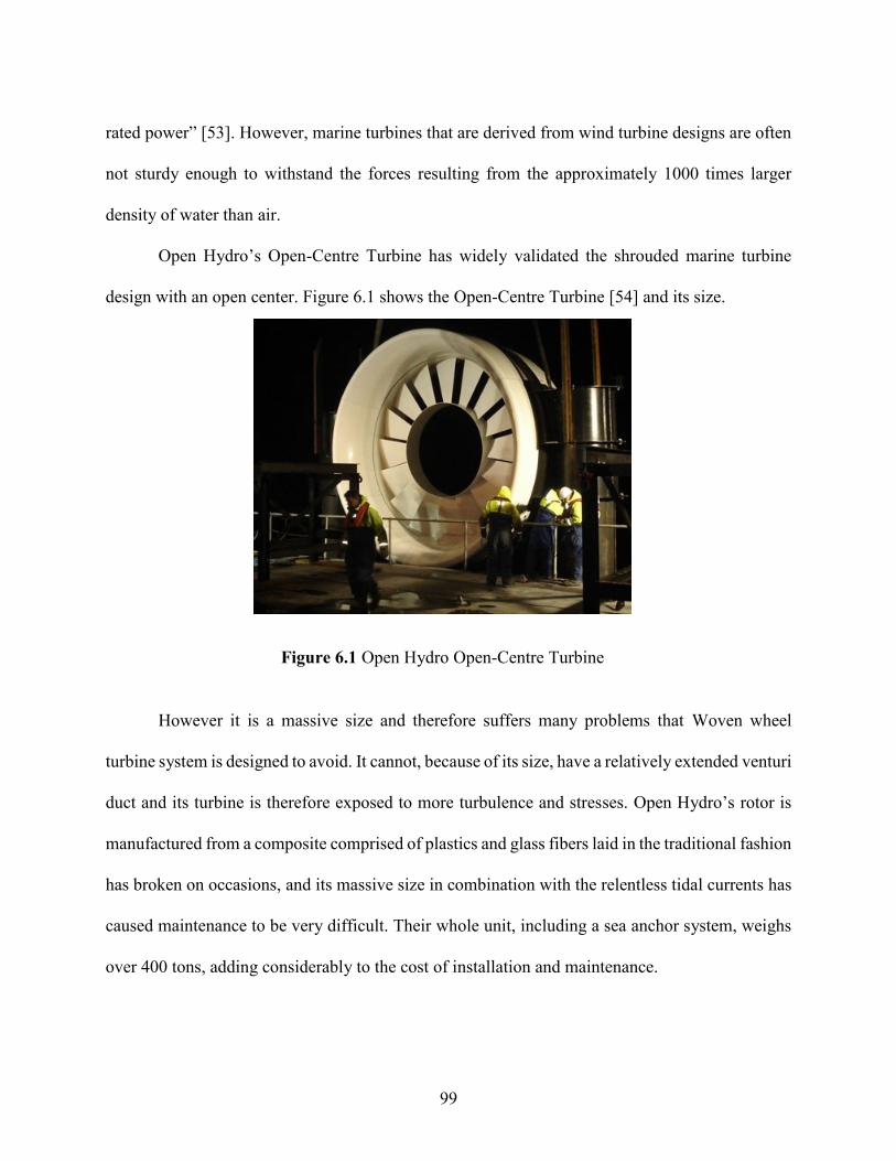
99
rated power” [53]. However, marine turbines that are derived from wind turbine designs are often
not sturdy enough to withstand the forces resulting from the approximately 1000 times larger
density of water than air.
Open Hydro’s Open-Centre Turbine has widely validated the shrouded marine turbine
design with an open center. Figure 6.1 shows the Open-Centre Turbine [54] and its size.
However it is a massive size and therefore suffers many problems that Woven wheel
turbine system is designed to avoid. It cannot, because of its size, have a relatively extended venturi
duct and its turbine is therefore exposed to more turbulence and stresses. Open Hydro’s rotor is
manufactured from a composite comprised of plastics and glass fibers laid in the traditional fashion
has broken on occasions, and its massive size in combination with the relentless tidal currents has
caused maintenance to be very difficult. Their whole unit, including a sea anchor system, weighs
over 400 tons, adding considerably to the cost of installation and maintenance.
Figure 6.1 Open Hydro Open-Centre Turbine
100
6.3 PROPOSED TECHNOLOGY
One of the major challenges with the use of traditional fiber-reinforced composite materials
for the blades is the mechanical connection of the blades to the torque transmitting elements like
the hub and the shaft. The largest stresses in the impeller are found in the area where the blades
connect to the hub, which in turn connects to the shaft. This configuration limits variations in the
design. Blades also can break when flexing at this location. The proposed technology builds on
the patented Woven Wheel design for turbomachinery, which has proven its structural integrity in
light-weight and high-strength axial compressor impellers.
The majority of the forces experienced by a woven compressor wheel are from the fluid
passing over the blades and centrifugal forces acting in the radial direction due to its own rotating
mass. However, in a marine environment the centrifugal forces are greatly reduced due to the
significantly reduced rotating speed. Therefore the main forces of consideration in marine turbines
are caused by the fluid moving over the blades and it is because of this that the impeller benefits
from being constructed from a strong and light-weight material. The lighter the impeller is, the
more easily it can rotate when flow passes through. It also reduces the safety risks are associated
with construction, transportation, and installation. Lighter weight also means that less force is
exerted on the bearings, and hence less maintenance.
All winding patterns result in a design with an outer shroud and with fibers aligned in the
direction of the forces associated with rotation. The outer shroud widely diminishes issues of blade
tip vortices, tip leakage, tip clearance, and adds additional strength in the tangential direction, thus
reducing vibrations. It also allows for an integrated generator at the outer diameter.
After the matrix material (resin) has cured, the mandrel can either be removed (with the
aid of a previously-applied mold-release agent), or it can remain in the impeller as a structural

101
element of the impeller especially if it is of magnetic material and used as an electromagnetic
element of an integrated motor/generator or bearing. Winding patterns like those shown in Table
2.1 (Chapter 2) were initially developed for use as a compressor, however many of the same
principles hold true for the design of a woven turbine. As be seen in the table, there are winding
patterns in which the fibers are aligned to form radial blades that cross through the center of the
axis of rotation (to bear the centrifugal force load associated with a high speed compressor). The
patterns that do not pass through the axis of rotation (hence non-radially aligned fibers) result in
unconventional blade shapes, but provide an opening in the center. These patterns can also provide
additional flow guidance near the hub area which can aid in preventing flow separation. All
patterns allow for curved or straight blades. There are currently several different methods to affix
the turbines in the tidal flow. These include seabed mounted (physically attached to the sea floor),
gravity base (using the shear mass of the structure to hold it in place), pile mounted (similar to
land based wind turbines – mounted on a large pole that goes beneath the surface of the seabed),
and tethered (including flexible mooring, rigid mooring, and floating structure tethering).
Although the Woven wheel turbines are flexible enough to use any of these, tethering is the best
option since it utilizes the neutral buoyancy inherent to the Woven wheel turbines due to their very
light weight.
Using a combination of these winding techniques, it is also possible to have radially aligned
blades with an open center through which wildlife can harmlessly pass. A study called “Marine
life interaction with tidal turbines” [55] done in Scotland modified the bird strike model developed
by Tucker in 1996 [56] for wind turbines to determine the likelihood of fish and marine mammals
colliding with marine turbines.
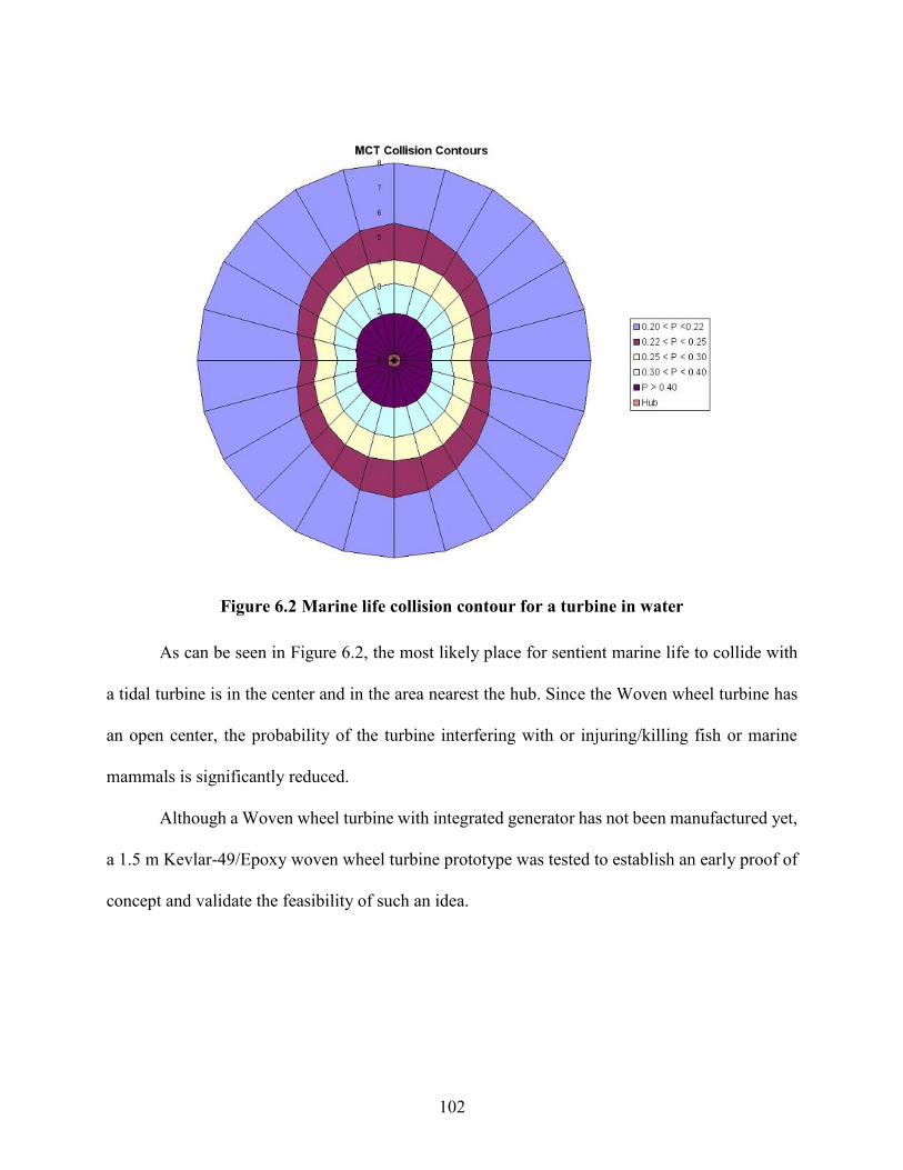
102
As can be seen in Figure 6.2, the most likely place for sentient marine life to collide with
a tidal turbine is in the center and in the area nearest the hub. Since the Woven wheel turbine has
an open center, the probability of the turbine interfering with or injuring/killing fish or marine
mammals is significantly reduced.
Although a Woven wheel turbine with integrated generator has not been manufactured yet,
a 1.5 m Kevlar-49/Epoxy woven wheel turbine prototype was tested to establish an early proof of
concept and validate the feasibility of such an idea.
Figure 6.2 Marine life collision contour for a turbine in water

103
Figure 6.3 Front view of the Woven wheel turbine inside the tow tank

104
6.4 EXPERIMENTAL SETUP AND RESULTS
A prototype Woven wheel turbine (axial configuration) with a 1.5m diameter rotor was
tested successfully in a tow tank at the Marine Hydrodynamic Lab, University of Michigan (Figure
6.4). The tow tank facility is shown in Figure 6.9, with the facility description summarized in Table
6.1. The rotor was made of wound Kevlar-49/Epoxy. During testing, the turbine was able to extract
about 0.5kW (15rpm at 3 knots), 1.1 kW (13rpm at 5 knots), and 2.5 kW (20 rpm at 7 knots).
Figure 6.3 shows the front view of the turbine setup in the tow tank. Figure 6.5 shows the
side view of the turbine setup and Figure 6.8 shows the top view setup.
Figure 6.4 Woven wheel turbine setup being submerged into the tow tank

105
Figure 6.5 Side view of the Woven wheel turbine inside the tow tank

106
Figure 6.6 Woven wheel turbine with the power transmitting mechanism
Figure 6.7 Load cells used for braking torque
measurement

107
A test frame was designed to support the turbine taking into consideration the thrust that
the frame would endure and the maximum torque that the shaft would transmit for a flow velocity
of 6.17m/s. The turbine was tested by mounting it in a moving carriage and driving it at a steady
speed, as far as possible, in still water (Figure 6.4). This is equivalent to mounting the turbine
under a fixed pontoon in moving water, but it has the advantage that the relative velocity between
the water and the turbine can be controlled. During testing, the rotational speed of the turbine was
recorded in RPM using a laser tachometer. To measure the torque, a disk brake system of a mid-
sized car was used (Figure 6.10). A button load cell (88964N, 20,000 lbs) was fixed under the
Figure 6.8 Top view of the Woven wheel turbine inside the tow tank

108
brake caliper, which is free to move along the disk. The load cell used is shown in Figure 6.7. As
the brake force is applied, the turbine slows to the desired rotational speed. The force associated
with this braking is directly taken from the load cell readout as the caliper presses on it. Zero load
reading is recorded for each run and an average value is subtracted from the total load cell force
reading. This force is then multiplied by the “moment arm”, or the length from the center of the
brake disk to the approximate center of the brake pad to determine the Torque. The Power
generated by the turbine is then calculated by multiplying the rotational speed by Torque. A chain
ratio of 19:9 is used to double the angular velocity at the RPM sensor. Furthermore, a reflective
tape with seven equidistant lines is stuck onto the surface of the shaft so that the actual RPM of
the turbine is RPM = (Sensor display)/7x (9/19). The data acquisition system mounted on the
moving carriage is show in Figure 6.11
Figure 6.9 Picture showing the end view of the tow tank facility

109
Figure 6.10 Disk brake system with load cell underneath for braking torque measurement
Figure 6.11 Data acquisition for measuring turbine rotational speed, load cell reading and
moving carriage speed

110
6.5 RESULTS
The measured length of the moment arm was 116 mm. A total of 42 test runs were made
within a span of 6-8 hours for moving carriage speeds of 3, 5 and 7 knots. Due to the acceleration
and deceleration of the carriage with given limited distance it could traverse limited by the length
of the tow tank, the steady state range was very narrow. The data was collected throughout the test
run and post processing of the data for the steady state range was then used for results. Figure 6.12
shows the post processed data for a standard run. As can be seen from the figure there is an evident
lag in the torque against the carriage speed. This could be because of the lag in gathering the brake
torque, as the process was manual and human error was involved. This run was one of the best
runs which generated a rotor power of about 2.5 KW at 7 knots (3.6 m/s). Since the goal of the
experiment was to establish the proof of concept, the impeller design was not necessarily
optimized. This is evident from a low power coefficient, indicating low efficiency.
Table 6.1 Description of the town tank facility

111
-0.50
0.00
0.50
1.00
1.50
2.00
2.50
3.00
3.50
4.00
-100.00
0.00
100.00
200.00
300.00
400.00
500.00
600.00
0.0
0.0
6.3
7.7
9.8
9.6
14
.0
17
.1
22
.8
19
.7
19
.6
20
.0
17
.6
11
.0
6.3
2.4
1.2
0.8
0.6
0.5
0.3
Po
wer
(K
W)
Wat
erSp
eed
(m
/s)
Torq
ue
(Nm
)
RPM
Chronological Torque and Power vs RPM #36
Torque Power Extracted Water Speed
Steady State
Figure 6.12 Plot showing the measured torque, power and carriage speed as a function of
the rotational speed of the turbine as the carriage moves from one end to another

112
Table 6.2 Summary of the measurements showing the TSR and Power Coefficient

113
6.6 FUTURE OF THE PROPOSED TECHNOLOGY
These underwater turbines will not only reduce air pollution compared to terrestrial power
stations, but it will also eliminate noise pollution. The use of light weight composite materials will
enable the turbine to have positive buoyancy. These turbine modules will have the potential to be
tethered to the seabed (using advanced oil industry semi-submersible technology) with the turbines
then held in place below the surface. This may be essential in locations such as Florida where the
main current is far above the seabed and therefore not exploitable by bottom-mounted devices.
Also this keeps the turbines out of the way of heavy debris on the sea bed or floating debris. The
design has a caisson and venturi surrounding the rotor. The caisson is designed to enhance the
power output for smaller wheel size. More importantly, the caisson protects the rotor by reducing
the lateral forces that might otherwise impinge on the wheels, further reducing the fluctuations in
forces, and hence fatigue, and therefore chances of failure.
The design is highly customizable to location. Modular, stackable, interlocking caissons
within a honeycomb structure will facilitate the nesting of units into concentrated arrays, the shape
of which would also be customized to the location and allow installation in infrastructure such as
Figure 6.13 Conceptual design showing stackable modular turbines tethered to seabed.

114
bridges and causeways. The fabrication method allows customized blade profiles, an effective
system of tuning, which may therefore be designed to suit site-specific flow characteristics. Woven
wheel turbine rotor design will work in currents slower than other marine energy technologies,
demonstrating the potential to generate electricity in a 1.5m/sec (approx 3 knots) and below current
velocity. The ability to operate in slow currents opens up more potential deployment locations for
the turbine systems, including those closer to population centers and grid connections. Costs for
installation and maintenance problems also diminish where current flow speeds are less.

115
CHAPTER 7: CONCLUSIONS
7.1 SUMMARY
The feasibility of winding/weaving light-weight, high-strength turbo-impellers
with integrated motor and bearings on a commercially available winding machine
has been successfully demonstrated. This method of manufacturing the impellers
results in dramatic cost reductions, and allows for the possibility of automation.
A prototype single stage compressor test loop for compressing water vapor is
designed and built. Scaled up results from the prototype testing show that it is
possible to achieve the necessary pressure ratio across multiple stages to compress
water vapor using this concept.
3-D finite element model of the impeller is generated and modeled with orthotropic
elastic material properties. Static structural analysis of impellers at 10,000 rpm (tip
speed = 252 m/s) and 90o C shows that carbon/epoxy impeller is structurally
superior in comparison to kevlar-49/epoxy and s-glass/epoxy impeller.
The vibrational characteristics of the bare impeller have been studied and the
Campbell plots mapped which present an overall (or bird’s-eye) view of the
regional vibration excitation that can occur on an operating system.
Effect of varying parameters like fiber type, shrouding, blade thickness, blade twist
angle, magnet positioning and magnet filler material on the structural behavior of
the impeller is presented leading to an optimized design of the integrated rotor.
Application of the woven wheel technology to tidal turbine applications is explored
and proof of concept established with an experiment in simulated conditions in a

116
tow tank. The woven wheel turbine prototype was able to generate a maximum of
2.5 KW power at 7 knots water velocity.
7.2 CONTRIBUTIONS
A major contribution to this research includes the manufacturing concept of the integrated
woven impeller. The feasibility of winding integrated rotors with permanent magnets is
established. This includes designing and performing first experimental setup for a single stage
counter rotating impellers as a part of an axial compressor. A new methodology for evaluating the
structural and vibrational behavior of the impeller is also established. The research isolates each
individual parameter and establishes its effect of the structural integrity of the impeller. A
technique for structural optimization of the integrated impellers is also developed. Other
contributions include exploring the application areas for the novel impeller including the concept
of a multi-stage counter rotating axial compressor for removal of non-condensable gases from a
geothermal power plant. The feasibility of using these impellers for tidal turbine applications is
explored and proof of concept established with a preliminary experiment in tow tank.
7.3 RECOMMENDATIONS AND FUTURE RESEARCH
The manufacturing approach could be enhanced with tighter quality control and
using techniques like vacuum bagging to reduce the voids and increase the fiber
volume fraction.
A multi-physics simulation approach should be considered which includes inputs
from fluid mechanics, structural analysis and motor design. With the advent of new
software’s like ANSYS WB it is possible to a single simulation that includes the
effects from CFD and they can be set as an input for FEA structural. This approach

117
also allows the possibility for automated design optimization using a design of
experiments type approach.
It would be a great step towards optimization if the 3-D modeling of the impellers
is parameterized. This save a lot of time, if the geometric design parameters need
to be changed later in the design or if geometry is a parameter in optimization.
Depending upon the support system of the integrated impeller, develop a numeric
rotordynamic model of the complete impeller, shaft (if any) and bearing assembly
with spring damper elements. The stiffness and damping of these elements could
be found from installing accelerometers on the actual system.
Conduct in-situ experiments on the impeller to find displacements and stresses
using strain gages or full-filed optical methods like digital image correlation,
interferometry or reflective photoelasticity.
To compare the performance improvement of a geothermal power plant using the
novel axial compressor over other methods, an exergetic analysis of the whole
thermodynamic system should be performed.

118
REFERENCES

119
REFERENCES
[1] Q. Li, "Design and Analysis of a Novel Composite Axial Impeller for Compressing Water
Vapor as Refrigerant," in PhD Thesis, Michigan State University, 2010.
[2] A. Kharazi, P. Akbari and N. Müller, "Analysis and performance prediction of an R-718
compression cycle with a 3-port condensing wave rotor," Journal of energy resources
technology, vol. 128, pp. 325-334, 2006.
[3] W. S.E, Y. T., L. D. B.A. and D. N. C., "The efficiency limits of water vapor compressors
suitable for air-conditioning applications," 2000.
[4] A. Kilicarslan and N. Müller, "COP's of R718 in comparison with other modern
refrigerants," in First Cappadocia Int. Mechanical Engineering, Cappadocia, Turkey,
2004.
[5] D. V. Orshoven, S. A. Klein and W. A. Beckman, "Investigation of water as a Refrigerant,"
Journal of Energy Resources Technology, vol. 115, no. 4, pp. 257-263, 1993.
[6] B. Lachner, G. Nellis and D. Reindl, "The commercial feasibility of the use of water vapor
as a refrigerant," International journal of refrigeration, vol. 30, no. 4, pp. 699-708, June
2007.
[7] J. Kühnl-Kinel, "new age water chillers with water as refrigerant," CERN -European
Organization for Nuclear Research, Geneva.
[8] P. J. and W. M.-J., "District cooling with water as refrigerant combined with energy storage
systems," Science et technique du froid, pp. 82-92, 1998.
[9] R. H. Aungier, "Axial-Flow compressions : A stretegy for aerodynamic design and
analysis," New York, ASME Press, 2003, p. Chapter 1.
[10] B. Burandt, "Technische Information R718-Turbo-Kaltwassersatz R718 chiller: technical
information.," 2004.
[11] N. Müller, ", “Entwurf von Laufrädern mit Radialfaserschaufeln für Diagonalverdichter
mit getrennt angetriebenen Vorläufer und Hauptläufer” (Design of mixed-flow
compressors with separately driven pre- and main runner with radial-line blading)," 1999.
[12] N. Müller, "Design of compressor impellers for water as a refrigerant," ASHRAE
Transactions, vol. 107, pp. 214-222, 2001.

120
[13] Q. G. Li and N. Müller, "Using filament winding approach to manufacture composite
impellers for water chiller," Journal of Advanced materials, vol. 42, no. 4, pp. 45-55, 2010.
[14] D. Cohen, S. Mantel and L. Zhao, "The effect of fiber volume fraction on filament wound
composite pressure vessel strength," Composites Engineering, vol. 32, no. 5, pp. 413-429,
2001.
[15] W. Raschi and C. Tabit, "Functional aspects of placoid scales: a review and update," Aust.
J. Mar. Freshwat. , vol. 43, pp. 123-147, 1992.
[16] W. E. Relf, "Morphogenesis and function of the squamation in sharks: Comparative
functional morphology of shark scales and ecology of scales," Neues. Jah. Geol. Palaeon.
Abh. , vol. 164, pp. 172-183, 1982.
[17] M. C. Potter and D. C. Wiggert, Mechanics of Fluids, CL-Engineering, 2001.
[18] R. Bertani, "Geothermal power generation in the world 2005-2010 update report," in World
geothermal congress, Bali, Indonesia, 2010.
[19] R. Bertani, "World geothermal power generation in the period 2001-2005," Geothermics,
pp. 651-669, 2005.
[20] H.Gupta and S.Roy, Worldwide status of geothermal resource utilization in geothermal
energy, an alternative resource for the 21st century, 1st, Ed., Oxford: Elsevier, 2007.
[21] M. Vorum and E. A. Fritzler, "Comparative Analysis of alternative means for removing
noncondensable gases from flash-steam geothermal power plants," NREL (National
Renewable Energy Laboratory), 2000.
[22] G. Cory, H. Guillen and D. Cruz, "Geothermal noncondensable gas removal from turbine
inlet steam," in Energy Conversion Engineering Conference, 1996.
[23] S.Tajima and M.Nomura, "Optimization of noncondensable gas removal in geothermal
power plant," Geothermal Resources Council Transactions, vol. 7, pp. 397-400, 1982.
[24] J.W.Hankin, G.F.Cochrane and V. d. Mast, "Geothermal power plant design for steam with
high noncondensable gas," Geothermal Resources Council Transactions, vol. 8, pp. 65-70,
1984.
[25] R. Perry, Chemical engineering handbook, 8th ed., McGraw Hill, 2008.
[26] H.Hamano, "Design of a geothermal power plant with high non-condensable gas content,"
Geothermal Resources Council Transactions, vol. 7, pp. 15-18, 1983.

121
[27] R.B.Swandaru, "Thermodynamic analysis of preliminary design of power plant unit I
Patuha, West Java Indonesia," Reykjavik, Iceland, 2006.
[28] N. Hall, "Gas extraction system in M.G. Dunstall," 1996.
[29] M.Forsha, K.E.Nichols and J.W.Shull, "Development and operation of a turbocompressor
for non-condensable gas removal at geothermal power plants," Geothermal Resources
Councill Transactions, vol. 23, pp. 59-63, 1999.
[30] Barber-Nichols Inc., "Barber Nichols home page," 2010. [Online]. Available:
http://www.barber-nichols.com/sites/default/files/wysiwyg/images/non-
condensable_gas_turbocompressor.pdf. [Accessed 2012].
[31] M.Forsha and K.Lankford, "Turbine driven compressor noncondensable gas removal at
geothermal steam power plants," Geothermal Resources COuncil Transactions , vol. 18,
pp. 523-529, 1994.
[32] L. Awerbuch, V. Van Der Mast and R. Soo-Hoo, "Review of upstream reboiler concept,"
Transactions geothermal Resources Council, pp. 21-26, 1984.
[33] G. G. Gunerhan, "An upstream reboiler design for removal of noncondensable gases from
geothermal steam for kizildere geothermal power plant, Turkey," Geothermics, pp. 739-
757, 1999.
[34] N. Y. Ozcan and G. Gokcen, "Thermodynamic assesment of gas removal systems for a
single-flash geothermal power plants," Applied Thermal Engineering, pp. 3246-3253,
2009.
[35] N. Y. Ozcan, "Modeling, simulation and optimization of flashed-steam geothermal power
plants from the point of view of noncondensable gas removal systems," Izmir Institute of
Technology [PhD Thesis], Turkey, 2010.
[36] N. Mueller, "Woven Turbomachine Impeller". USA Patent US 7,938,627 B2, 2011.
[37] Q. Li, J. Piechna and N. Müller, "Design of a novel axial impeller as a part of counter-
rotating axial compressor to compress water vapor as refigerant," Applied Energy, pp.
3156-3168, 2011.
[38] Q. Li, J. Wang and N. Müller, "On the realization of filament wound composite impeller
for water refrigerant," in IMECE, 2009.
[39] M. W. Hyer, Stress analysis of fiber-reinforced composite materilas, DEStech Publications,
Inc, 2009.

122
[40] I. M. Daniel and O. Ishai, Engineering mechanics of Composite Materials, 3rd ed., Oxford
University Press, 2005.
[41] "Failure Theories for Fiber-Reinforced Materials," in Stress Analysis of Fiber-Reinforced
Composite Materials, DEStech Publication, Inc, 2009, pp. 395-396.
[42] Q. Li, J. Piechna and N. Müller, "Simulation of fatigue failure in composite axial
compressor blades," Materials and Design, vol. 32, pp. 2058-2065, 2011.
[43] "Abaqus Documentation 6.9".
[44] M. P. Boyce, Gas Turbine Engineering Handbook, 3rd ed., Gulf Professional Publishing.
[45] N. D'Orsi, S. WIght and T. Yoshinaka, "Design point performance trends for water vapor
compressors," in IMECE, 2001.
[46] M. Patil and N. Mueller, "Structural analysis of continuous fiber wound composite
impellers of a multistage high-speed counter rotating axial compressor for compressing
water vapor (R-718) as refrigerant using Finite Element Analysis," Materials & Design,
vol. 50, pp. 683-693, 2013.
[47] F. Akwensivie, P. Chandra, C. McAlister, R. Murray and N. Sullivan, "Marine Current
Energy Baseload Supply Strategy for Scotland," University of Strathclyde, 2003-2004.
[48] P. F.L.Ponta, "Marine current power generation by diffuser-augmented floating hydro-
turbines," Renewable Energy, vol. 33, pp. 2205-2211, 2008.
[49] A.S.Bahaj, W.M.J.Batten and G.McCann, "Experimental verification of numerical
predictions for the hydrodynamic performance of horizontal axis marine current turbines,"
Renewable Energy, vol. 32, pp. 2479-2490, 2007.
[50] A.S.Bahaj and L.E.Myers, "Fundamental application to the utilization of marine current
turbines for energy production," Renewable Energy, pp. 2205-2211, 2003.
[51] G. Marsh, "Wave and tidal power-an emerging new market for composites," Reinforced
plastics, pp. 20-24, June/July 2009.
[52] "Energy System Research Unit : Marine Current Resource and Technology Methodology,"
University of Strathclyde. [Online]. [Accessed 2013].
[53] "Performance: Marine Current Turbines," SeaGen-Technology, [Online]. Available:
http://www.marineturbines.com/SeaGen-Technology/Performance. [Accessed 2013].
[54] "Open Hydro Tidal Technology," openhydro, [Online]. Available: www.openhydro.com.

123
[55] B. Henry, N. Koronka, R. Turbet and J. Meason, "Marine Life Interaction with Tidal
Turbines," Marine Environmental Consultant Services, Glasgow UK.
[56] V. Tucker, "A Mathematicl model of bird collisions with wind turbine rotors," journal of
solar engineering, vol. 118, no. 4, pp. 252-262, 1996.