Embed Size (px)
Citation preview
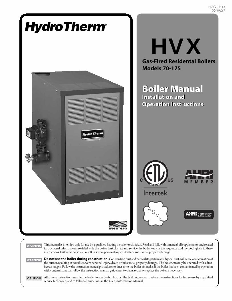
Boiler ManualInstallation and Operation Instructions
This manual is intended only for use by a qualified heating installer/technician. Read and follow this manual, all supplements and relatedinstructional information provided with the boiler. Install, start and service the boiler only in the sequence and methods given in theseinstructions. Failure to do so can result in severe personal injury, death or substantial property damage.
Do not use the boiler during construction. Construction dust and particulate, particularly drywall dust, will cause contamination ofthe burner, resulting in possible severe personal injury, death or substantial property damage. The boiler can only be operated with a dust-free air supply. Follow the instruction manual procedures to duct air to the boiler air intake. If the boiler has been contaminated by operationwith contaminated air, follow the instruction manual guidelines to clean, repair or replace the boiler if necessary.
Affix these instructions near to the boiler/water heater. Instruct the building owner to retain the instructions for future use by a qualifiedservice technician, and to follow all guidelines in the User’s Information Manual.
HVXGas-Fired Residental BoilersModels 70-175
Boiler ManualInstallation and Operation Instructions
HVX2-031322-HVX2

2
TABLE OF CONTENTS
USING THIS MANUAL 3A. INSTALLATION SEQUENCE . . . . . . . . . . . . .3B. SPECIAL ATTENTION BOXES . . . . . . . . . . . .3
1. PREINSTALLATION 4
A. ACCESSIBILITY CLEARANCES . . . . . . . . . . .4B. CLEARANCE FROM COMBUSTIBLE
CONSTRUCTION . . . . . . . . . . . . . . . . . . . . . .4C. AIR FOR COMBUSTION AND
VENTILATION . . . . . . . . . . . . . . . . . . . . . . . . .5
D. PLANNING THE LAYOUT . . . . . . . . . . . . . . . .8
E. MASSACHUSETTS INSTALLATIONS . . . . . .8
2. BOILER SET-UP 8
3. WATER PIPING AND CONTROLS 9A. BOILER SUPPLY AND RETURN . . . . . . . . . . .9B. SAFETY RELIEF VALVE . . . . . . . . . . . . . . . .10C. PIPING FOR ZONED SYSTEMS . . . . . . . . . .11D. EXPANSION TANK . . . . . . . . . . . . . . . . . . . .12E. INDIRECT-FIRED WATER HEATER . . . . . . . .12F. FREEZE PROTECTION . . . . . . . . . . . . . . . . .12
4. VENTING 13A. GENERAL . . . . . . . . . . . . . . . . . . . . . . . . . . .13B. CHIMNEY VENTING . . . . . . . . . . . . . . . . . . .13C. DIRECT EXHAUST
HORIZONTAL VENTING- . . . . . . . . . . . . . . .13D. DIRECT EXHAUST
VERTICAL VENTING . . . . . . . . . . . . . . . . . .16E. BOILER REMOVAL FROM
COMMON VENTING SYSTEM . . . . . . . . . .17
5. GAS PIPING 18
6. ELECTRICAL 20A. WIRING . . . . . . . . . . . . . . . . . . . . . . . . . . . . .20B. ZONED SYSTEM WIRING . . . . . . . . . . . . . .20C. CONTROLS . . . . . . . . . . . . . . . . . . . . . . . . . .20D. BOILER SEQUENCE OF OPERATION . . . . .22
7. START-UP PROCEDURES 22A. COMPLETING THE INSTALLATION . . . . . . .22B. CONTROL DESCRIPTIONS . . . . . . . . . . . . .26C. ADJUSTMENT OF GAS PRESSURE
REGULATOR . . . . . . . . . . . . . . . . . . . . . . . . .26D. CHECKING BURNER INPUT . . . . . . . . . . . . .26E. CHECK-OUT PROCEDURE . . . . . . . . . . . . . .27
8. TROUBLESHOOTING 29A. SHUT-DOWN CAUSED BY PILOT OUTAGE,
PRESSURE SWITCH OR FLAME ROLL-OUT SAFETY SHUT-OFF SWITCH . . . . . . . . . . . .29
B. TROUBLESHOOTING GUIDES . . . . . . . . . .29C. MEASURING SUCTION PRESSURE . . . . . .29
9. MAINTENANCE 32A. GENERAL . . . . . . . . . . . . . . . . . . . . . . . . . . .33B. DAILY (WITH BOILER IN USE) . . . . . . . . . . .33C. WEEKLY (WITH BOILER IN USE) . . . . . . . . .33D. MONTHLY (WITH BOILER IN USE) . . . . . . .33E. ANNUALLY (BEFORE START OF HEATING
SEASON) . . . . . . . . . . . . . . . . . . . . . . . . . . .34
10. BOILER DIMENSIONS & RATINGS 35
11. REPAIR PARTS 36A. BLOCK/BASE/FLOOR PAN
JACKET/FLUE COLLECTOR . . . . . . . . . . . . .36B. BASE/BURNERS/MANIFOLD . . . . . . . . . . . .38
TABLE OF CONTENTS
3
USING THIS MANUAL
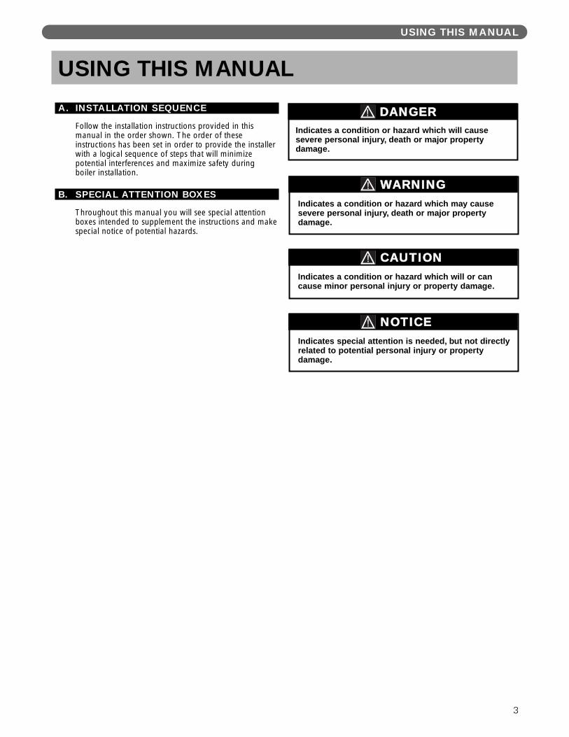
A. INSTALLATION SEQUENCE
Follow the installation instructions provided in thismanual in the order shown. The order of theseinstructions has been set in order to provide the installerwith a logical sequence of steps that will minimizepotential interferences and maximize safety duringboiler installation.
B. SPECIAL ATTENTION BOXES
Throughout this manual you will see special attentionboxes intended to supplement the instructions and makespecial notice of potential hazards.
Indicates special attention is needed, but not directlyrelated to potential personal injury or propertydamage.
NOTICE
Indicates a condition or hazard which will or cancause minor personal injury or property damage.
CAUTION
DANGERIndicates a condition or hazard which will causesevere personal injury, death or major propertydamage.
USING THIS MANUAL
Indicates a condition or hazard which may causesevere personal injury, death or major propertydamage.
WARNING
A. ACCESSIBILITY CLEARANCESInstall boiler not less than 24″ (610 mm) between the leftside, top, and front of the boiler and adjacent wall orother appliance, when access is required for servicing.
B. CLEARANCE FROM COMBUSTIBLE CONSTRUCTIONThe design of this boiler is certified for closet installationwith the following clearances:
1. 6″ (152 mm) between sides, rear and front andcombustible construction.
2. 24″ (610 mm)between top of jacket and combustible construction.
3. 2″ (51 mm) between vent pipe and combustibleconstruction.
PREINSTALLATION
1. PREINSTALLATIONRead carefully, study these instructions before beginning work.
This boiler must be installed by a qualified contractor.
The boiler warranty can be voided if the boiler is not installed, maintained and serviced correctly.
The equipment must be installed in accordance with those installation requirements of the authority having jurisdiction or, in the absence of such requirements, to the current edition of the National Fuel Gas Code, ANSIZ223.1/NFPA 54 and/or CAN/CSA B149.1, Natural Gas and Propane Installation Code.
Where required by the authority having jurisdiction, the installation must conform to American Society ofMechanical Engineers Safety Code for Controls and Safety Devices for Automatically Fired Boilers, ANSI/ASME CSD-1.
NOTICE
Do not install this boiler on carpeting. Boilerinstallation on carpeting is a fire hazard. Install thisboiler on non-combustible flooring or use acombustible floor pan to install this boiler on othernon-carpeted flooring.
DANGER
Do not install this boiler on combustible flooringunless it is installed on a special combustible floorpan. Boiler installation on combustible flooringwithout the special pan is a fire hazard.
To order combustible floor pan, use the 5-digit stockcodes listed in Section 11 of this manual.
DANGER
In accordance with Section 325 (f) (3) of the Energy Policy and Conservation Act, this boiler is equipped with afeature that saves energy by reducing the boiler water temperature as the heating load decreases. This feature isequipped with an override which is provided primarily to permit the use of an external energy managementsystem that serves the same function.
THIS OVERRIDE MUST NOT BE USED UNLESS AT LEAST ONE OF THE FOLLOWING CONDITIONS IS TRUE:
• An external energy management system is installed that reduces the boiler water temperature as theheating load decreases.
• This boiler is not used for any space heating
• This boiler is part of a modular or multiple boiler system having a total input of 300,000 BTU/hr or greater.
• This boiler is equipped with a tankless coil.
IMPORTANT
4
C. AIR FOR COMBUSTION ANDVENTILATION
1. Adequate combustion air and ventilation air must beprovided in accordance with section 5.3, Air forCombustion and Ventilation, of the National FuelGas Code, ANSI Z223.1/NFPA 54, or Sections 7.2,7.3 or 7.4 of CAN/CSA B149.1, Natural Gas andPropane Installation Code or applicable provisions ofthe local building code. Subsections 2 through 8 asfollows are based on the National Fuel Gas Coderequirements.
2. Required Combustion Air Volume: The total requiredvolume of indoor air is to be the sum of the requiredvolumes for all appliances located within the space.Rooms communicating directly with the space inwhich the appliances are installed and throughcombustion air openings sized as indicated inSubsection 3 are considered part of the requiredvolume. The required volume of indoor air is to bedetermined by one of two methods.
a. Standard Method: The minimum requiredvolume of indoor air (room volume) shall be 50cubic feet per 1000 BTU/Hr (4.8 m3/kW). Thismethod is to be used if the air infiltration rate isunknown or if the rate of air infiltration is knownto be greater than 0.6 air changes per hour. Asan option, this method may be used if the airinfiltration rate is known to be between 0.6 and0.4 air changes per hour. If the air infiltration rateis known to be below 0.4 then the Known AirInfiltration Rate Method must be used. If thebuilding in which this appliance is to be installedis unusually tight, we recommend that the airinfiltration rate be determined.
b. Known Air Infiltration Rate Method: Wherethe air infiltration rate of a structure is known,the minimum required volume of indoor air forthe Boiler and other fan assisted appliances shallbe determined as follows:
where:Ifan = Input of the fan assisted appliances in
Btu/hrACH = air change per hour (percent of the
volume of the space exchanged perhour, expressed as a decimal)
For appliances other than fan assisted, calculatethe required volume of air using the followingequation:
Iother = Input of appliances other than fanassisted in Btu/hr
Note: These calculations are not to be used forinfiltration rates greater than 0.60 ACH.
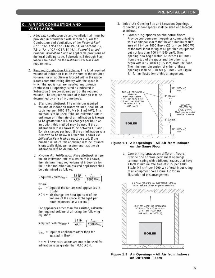
3. Indoor Air Opening Size and Location: Openingsconnecting indoor spaces shall be sized and locatedas follows:a. Combining spaces on the same floor:
Provide two permanent openings communicatingwith additional spaces that have a minimum freearea of 1 in2 per 1000 Btu/hr (22 cm2 per 1000 W)of the total input rating of all gas fired equipmentbut not less than 100 in2 (645 cm2). Oneopening is to begin within 12 inches (305 mm)from the top of the space and the other is tobegin within 12 inches (305 mm) from the floor.The minimum dimension of either of theseopenings shall be 3 inches (76 mm). See Figure1.1 for an illustration of this arrangement.
b. Combining spaces on different floors:Provide one or more permanent openingscommunicating with additional spaces that havea total minimum free area of 2 in2 per 1000Btu/hr (44 cm2 per 1000 W) of total input ratingof all equipment. See Figure 1.2 for anillustration of this arrangement.
PREINSTALLATION
Figure 1.1: Air Openings – All Air from Indoorson the Same Floor
Figure 1.2: Air Openings – All Air from Indoorson Different Floors
15 ft3 I fan
ACH 1000Btu/hrRequired Volumefan = ( )
21 ft3 I other
ACH 1000Btu/hrRequired Volumeother = ( )
5
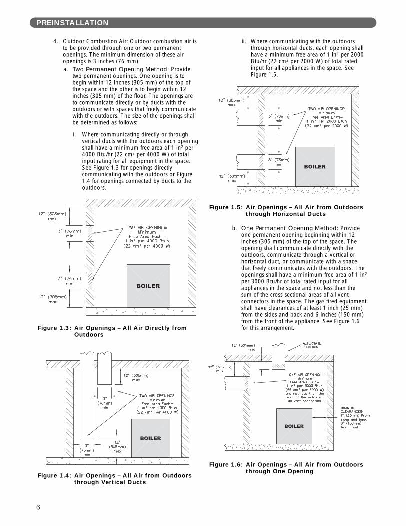
4. Outdoor Combustion Air: Outdoor combustion air isto be provided through one or two permanentopenings. The minimum dimension of these airopenings is 3 inches (76 mm).a. Two Permanent Opening Method: Provide
two permanent openings. One opening is tobegin within 12 inches (305 mm) of the top ofthe space and the other is to begin within 12inches (305 mm) of the floor. The openings areto communicate directly or by ducts with theoutdoors or with spaces that freely communicatewith the outdoors. The size of the openings shallbe determined as follows:
i. Where communicating directly or throughvertical ducts with the outdoors each openingshall have a minimum free area of 1 in2 per4000 Btu/hr (22 cm2 per 4000 W) of totalinput rating for all equipment in the space.See Figure 1.3 for openings directlycommunicating with the outdoors or Figure1.4 for openings connected by ducts to theoutdoors.
ii. Where communicating with the outdoorsthrough horizontal ducts, each opening shallhave a minimum free area of 1 in2 per 2000Btu/hr (22 cm2 per 2000 W) of total ratedinput for all appliances in the space. SeeFigure 1.5.
b. One Permanent Opening Method: Provideone permanent opening beginning within 12inches (305 mm) of the top of the space. Theopening shall communicate directly with theoutdoors, communicate through a vertical orhorizontal duct, or communicate with a spacethat freely communicates with the outdoors. Theopenings shall have a minimum free area of 1 in2
per 3000 Btu/hr of total rated input for allappliances in the space and not less than thesum of the cross-sectional areas of all ventconnectors in the space. The gas fired equipmentshall have clearances of at least 1 inch (25 mm)from the sides and back and 6 inches (150 mm)from the front of the appliance. See Figure 1.6for this arrangement.
Figure 1.5: Air Openings – All Air from Outdoorsthrough Horizontal Ducts
Figure 1.6: Air Openings – All Air from Outdoorsthrough One Opening
Figure 1.4: Air Openings – All Air from Outdoorsthrough Vertical Ducts
PREINSTALLATION
Figure 1.3: Air Openings – All Air Directly fromOutdoors
6
5. Combination Indoor and Outdoor Combustion Air:If the required volume of indoor air exceeds theavailable indoor air volume, outdoor air openings orducts may be used to supplement the availableindoor air provided:a. The size and location of the indoor openings
comply with Subsection 3.
b. The outdoor openings are to be located inaccordance with Subsection 4.
c. The size of the outdoor openings are to be sizedas follows:
where:Areq = minimum area of outdoor openings.Afull = full size of outdoor openings calculated
in accordance with Subsection 4.Vavail = available indoor air volumeVreq = required indoor air volume
6. Engineered Installations: Engineered combustion airinstallations shall provide an adequate supply ofcombustion, ventilation, and dilution air and shall beapproved by the authority having jurisdiction.
7. Mechanical Combustion Air Supply:
a. In installations where all combustion air isprovided by a mechanical air supply system, thecombustion air shall be supplied from theoutdoors at the minimum rate of 0.35 ft3/min per1000 Btu/hr (0.034 m3/min per 1000 W) of thetotal rated input of all appliances in the space.
b. In installations where exhaust fans are installed,additional air shall be provided to replace theexhaust air.
c. Each of the appliances served shall beinterlocked to the mechanical air supply toprevent main burner operation where themechanical air supply system is not in operation.
d. In buildings where the combustion air is providedby the mechanical ventilation system, the systemshall provide the specified combustion air rate inaddition to the required ventilation air.
8. Louvers & Grills:a. The required size of openings for combustion,
ventilation, and dilution air shall be based on thenet free area of each opening.
i. Where the free area through a louver or grilleis known, it shall be used in calculating theopening size required to provide the free areaspecified.
ii. Where the free area through a louver or grilleis not known, it shall be assumed that woodenlouvers will have 25% free area and metallouvers and grilles will have 75% free area.
iii. Nonmotorized dampers shall be fixed in theopen position.
b. Motorized dampers shall be interlocked with theequipment so that they are proven in the fullopen position prior to ignition and duringoperation of the main burner.
i. The interlock shall prevent the main burnerfrom igniting if the damper fails to openduring burner startup.
ii. The interlock shall shut down the burner ifthe damper closes during burner operation.
9. Combustion Air Ducts:a. Ducts shall be constructed of galvanized steel or
an equivalent corrosion- resistant material.
b. Ducts shall terminate in an unobstructed space,allowing free movement of combustion air to theappliances.
c. Ducts shall serve a single space.
d. Ducts shall not serve both upper and lowercombustion air openings where both suchopenings are used. The separation between ductsserving upper and lower combustion airopenings shall be maintained to the source ofcombustion air.
e. Ducts shall not be screened where terminating inan attic space.
f. Horizontal upper combustion air ducts shall notslope downward toward the source of thecombustion air.
g. The remaining space surrounding a chimneyliner, gas vent, special gas vent, or plastic pipinginstalled within a masonry, metal, or factory builtchimney shall not be used to supply combustionair.
h. Combustion air intake openings located on theexterior of buildings shall have the lowest side ofthe combustion air intake opening at least 12inches (305 mm) above grade.
Liquefied Petroleum (LP) is heavier than air and maycollect or “pool” in a low area in the event of a leakfrom defective equipment. This gas may then ignite,resulting in a fire or explosion.
WARNING
PREINSTALLATION
Vavail1 – Vreq
Areq = Afull x ( )
7
1. Provide a sound, level foundation. Locate boiler asnear to the chimney or outside wall as possible andcentralized with respect to the heating system.
2. Locate boiler in front of installation position before removing crate.
3. If using combustible floor pan, position pan onfoundation or flooring.
4. Separate the wood shipping pallet from the boilerbase by removing two (2) hold-down bolts at eachend of the boiler base.
5. Move boiler into final position. If using combustiblefloor pan, install boiler on pan as outlined in theinstructions included with the pan.
2. BOILER SET-UP
PREINSTALLATION
8
D. PLANNING THE LAYOUTPrepare sketches and notes of the layout to minimize thepossibility of interferences with new or existingequipment, piping, venting and wiring.
E. MASSACHUSETTS INSTALLATIONS
Massachusetts requires manufacturers of Side WallVented boilers to provide the following informationfrom the Massachusetts code:
• A hard wired carbon monoxide detector with analarm and battery back-up must be installed onthe floor level where the gas equipment is to beinstalled AND on each additional level of thedwelling, building or structure served by the sidewall horizontal vented gas fueled equipment.
• In the event that the side wall horizontally ventedgas fueled equipment is installed in a crawl spaceor an attic, the hard wired carbon monoxidedetector with alarm and battery back-up may beinstalled on the next adjacent floor level.
• Detector(s) must be installed by qualified licensedprofessionals.
• APPROVED CARBON MONOXIDEDETECTORS: Each carbon monoxide detectorshall comply with NFPA 720 and be ANSI/UL2034 listed and IAS certified.
• SIGNAGE: A metal or plastic identification plateshall be permanently mounted to the exterior ofthe building at a minimum height of eight (8) feetabove grade directly in line with the exhaust ventterminal for the horizontally vented gas fueledheating appliance or equipment. The sign shallread, in print size no less than one-half (1/2) inchin size, “GAS VENT DIRECTLY BELOW.KEEP CLEAR OF ALL OBSTRUCTIONS”.
• EXEMPTIONS to the requirements listed above:
° The above requirements do not apply if theexhaust vent termination is seven (7) feet ormore above finished grade in the area of theventing, including but not limited to decksand porches.
° The above requirements do not apply to aboiler installed in a room or structure separatefrom the dwelling, building or structure usedin whole or in part for residential purposes.See the latest edition of Massachusetts Code248 CMR for complete verbage and also foradditional (non-vent related) requirements(248 CMR is available online).
If your installation is NOT in Massachusetts, pleasesee your authority of jurisdiction for requirementsthat may be in effect in your area. In the absence ofsuch requirements, follow the National Fuel GasCode, ANSI Z223.1/NFPA 54 and/or CAN/CSAB149.1, Natural Gas and Propane Installation Code.
Venting System Installation Instructions – Seeboiler manual and instructions provided with theVenting System components. Additional copies maybe obtained from the Venting System Manufacturerby visiting the following web addresses:
Heat-Fab – www.selkirkcorp.com/heatfabZ-Flex – www.NovaFlex.comPro-Tech – www.protechinfo.comMetal-Fab – www.mtlfab.com
WATER PIPING AND CONTROLS
9
A. BOILER SUPPLY AND RETURN
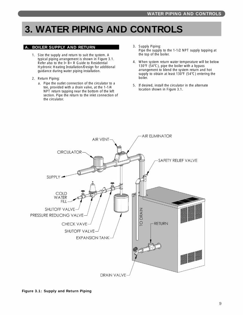
1. Size the supply and return to suit the system. Atypical piping arrangement is shown in Figure 3.1.Refer also to the I=B=R Guide to ResidentialHydronic Heating Installation/Design for additionalguidance during water piping installation.
2. Return Piping:a. Pipe the outlet connection of the circulator to a
tee, provided with a drain valve, at the 1-1/4NPT return tapping near the bottom of the leftsection. Pipe the return to the inlet connection ofthe circulator.
3. Supply Piping:Pipe the supply to the 1-1/2 NPT supply tapping atthe top of the boiler.
4. When system return water temperature will be below130°F (54°C), pipe the boiler with a bypassarrangement to blend the system return and hotsupply to obtain at least 130°F (54°C) entering theboiler.
5. If desired, install the circulator in the alternatelocation shown in Figure 3.1.
3. WATER PIPING AND CONTROLS
Figure 3.1: Supply and Return Piping
6. Install this boiler so that the gas ignition systemcomponents are protected from water (dripping,spraying, etc.) during appliance operation andservice (circulator replacement, condensate trap,control replacements, etc.).
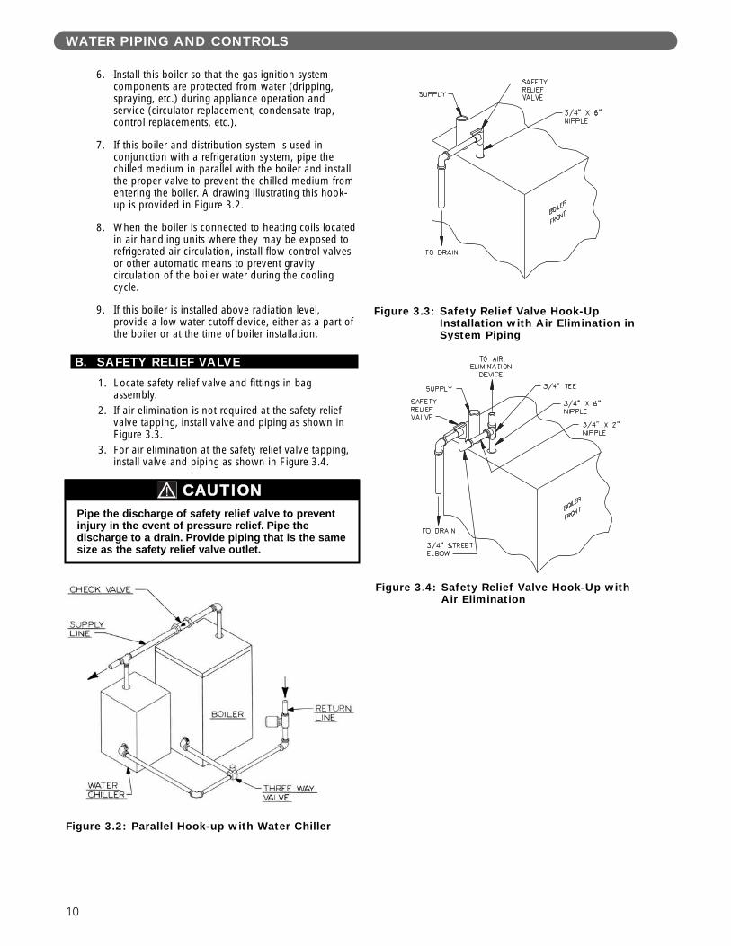
7. If this boiler and distribution system is used inconjunction with a refrigeration system, pipe thechilled medium in parallel with the boiler and installthe proper valve to prevent the chilled medium fromentering the boiler. A drawing illustrating this hook-up is provided in Figure 3.2.
8. When the boiler is connected to heating coils locatedin air handling units where they may be exposed torefrigerated air circulation, install flow control valvesor other automatic means to prevent gravitycirculation of the boiler water during the coolingcycle.
9. If this boiler is installed above radiation level,provide a low water cutoff device, either as a part ofthe boiler or at the time of boiler installation.
B. SAFETY RELIEF VALVE
1. Locate safety relief valve and fittings in bagassembly.
2. If air elimination is not required at the safety reliefvalve tapping, install valve and piping as shown inFigure 3.3.
3. For air elimination at the safety relief valve tapping,install valve and piping as shown in Figure 3.4.
Pipe the discharge of safety relief valve to preventinjury in the event of pressure relief. Pipe thedischarge to a drain. Provide piping that is the samesize as the safety relief valve outlet.
CAUTION
Figure 3.4: Safety Relief Valve Hook-Up withAir Elimination
Figure 3.3: Safety Relief Valve Hook-UpInstallation with Air Elimination in System Piping
Figure 3.2: Parallel Hook-up with Water Chiller
WATER PIPING AND CONTROLS
10
WATER PIPING AND CONTROLS
11
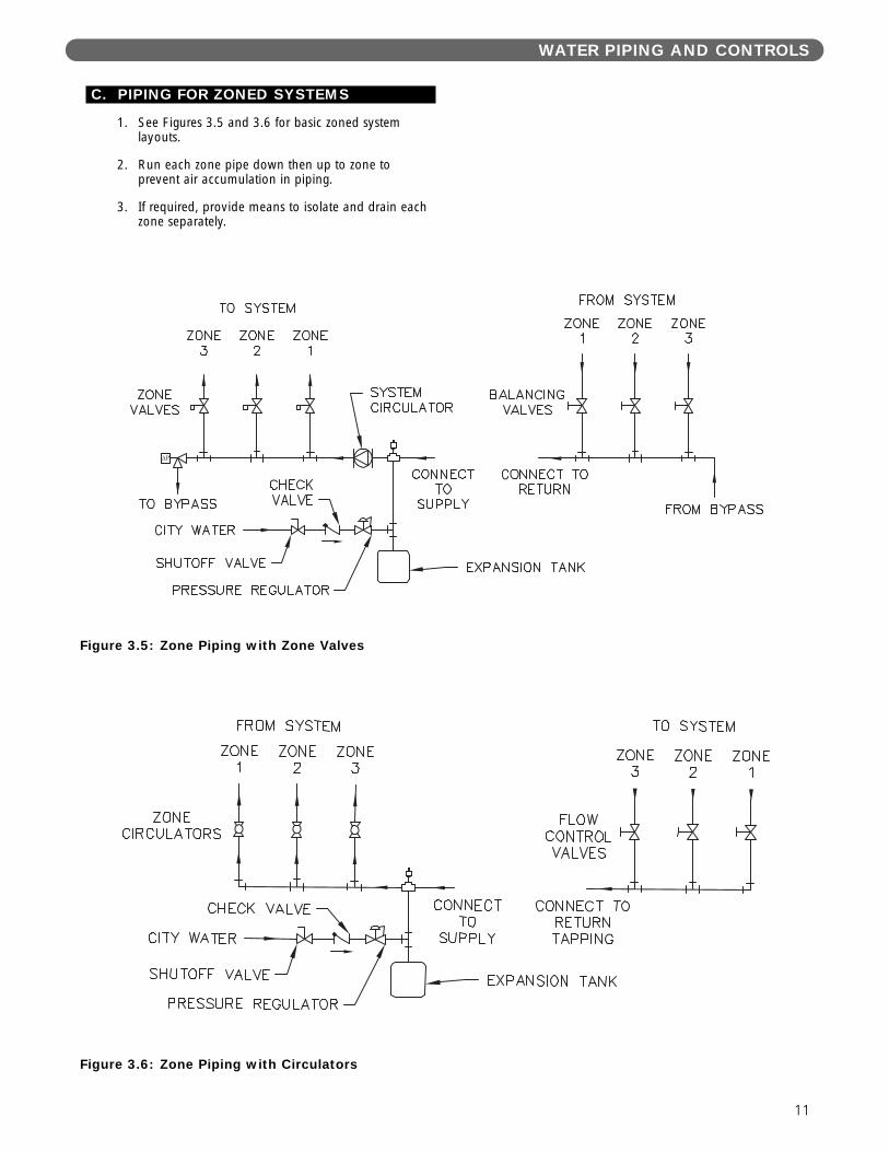
C. PIPING FOR ZONED SYSTEMS
1. See Figures 3.5 and 3.6 for basic zoned systemlayouts.
2. Run each zone pipe down then up to zone toprevent air accumulation in piping.
3. If required, provide means to isolate and drain eachzone separately.
Figure 3.5: Zone Piping with Zone Valves
Figure 3.6: Zone Piping with Circulators
D. EXPANSION TANK
1. Consult the tank manufacturer’s instructions forspecific information relating to tank installation. Sizethe expansion tank for the required system volumeand capacity. See Table 10.2 in Section 10 for boilerwater capacity.
2. Expansion tanks are available with built-in fill valvesand check valves for reducing supply water pressureand maintaining minimum system pressure. Checkthe design features of the tank and provide valves asnecessary.
Refer back to Figure 3.1 for typical expansion tank piping.
E. INDIRECT-FIRED WATER HEATER
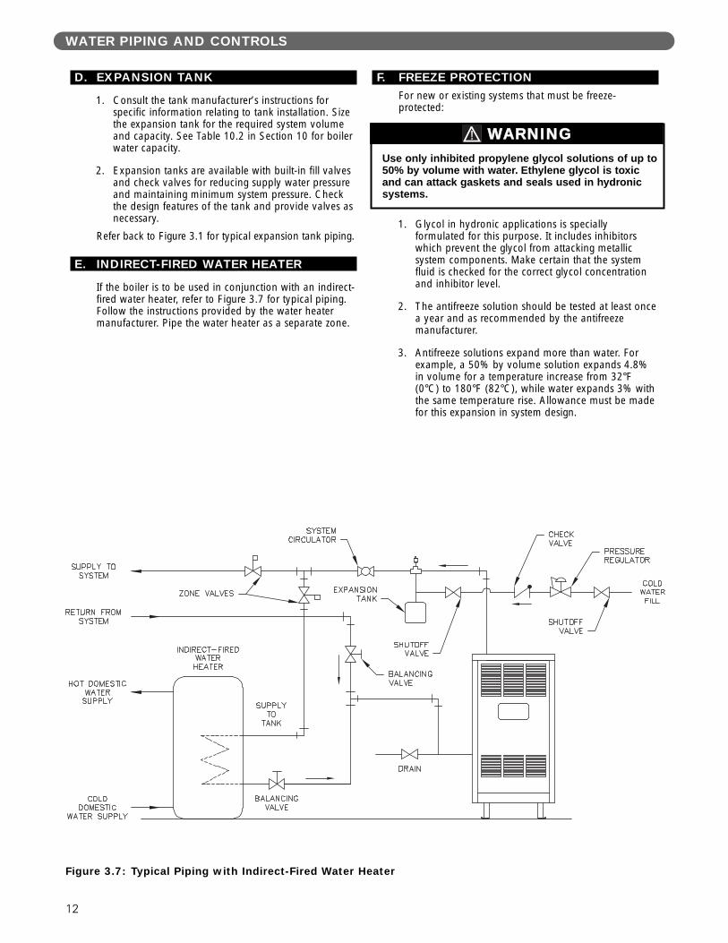
If the boiler is to be used in conjunction with an indirect-fired water heater, refer to Figure 3.7 for typical piping.Follow the instructions provided by the water heatermanufacturer. Pipe the water heater as a separate zone.
F. FREEZE PROTECTIONFor new or existing systems that must be freeze-protected:
1. Glycol in hydronic applications is speciallyformulated for this purpose. It includes inhibitorswhich prevent the glycol from attacking metallicsystem components. Make certain that the systemfluid is checked for the correct glycol concentrationand inhibitor level.
2. The antifreeze solution should be tested at least oncea year and as recommended by the antifreezemanufacturer.
3. Antifreeze solutions expand more than water. Forexample, a 50% by volume solution expands 4.8%in volume for a temperature increase from 32°F(0°C) to 180°F (82°C), while water expands 3% withthe same temperature rise. Allowance must be madefor this expansion in system design.
Figure 3.7: Typical Piping with Indirect-Fired Water Heater
Use only inhibited propylene glycol solutions of up to50% by volume with water. Ethylene glycol is toxicand can attack gaskets and seals used in hydronicsystems.
WARNING
WATER PIPING AND CONTROLS
12
VENTING
13
A. GENERAL
1. Install vent system in accordance with the “Ventingof Equipment” Chapter of the National Fuel GasCode, ANSI Z223.1/NFPA 54, the “Venting Systemsand Air Supply for Appliances” Section of theCAN/CSA B149.1, Natural Gas and PropaneInstallation Code. or applicable provisions of thelocal building codes.
2. Do not connect vent connectors serving appliancesvented by natural draft into any portion ofmechanical draft systems operating under positivepressure.
3. Refer to the following venting options to determinewhich method is applicable.ON –
B. CHIMNEY VENTING
If venting into a masonry chimney; chimney must belined with a fire clay tile liner or corrosion resistant metalliner. Type B vent may also be used as a lining system oras a stand alone chimney vent.
1. The vent system, when installed per the followinginstructions, will operate with a negative pressure (draft).
2. Horizontal portions of the vent pipe shall slopeupward from the boiler towards the vertical vent notless than 1/4" per foot (21 mm per meter). Supporthorizontal portions of the venting system to preventsagging by use of metal strapping or equivalentmeans. Locate supports at no more than 4 foot (1.2meter) intervals.
Parties horizontales de l'évent doit pente ascendantede la chaudière vers la cheminée verticale d'aumoins 1/4 "par pied (21 mm par mètre). Fournir unsupport à toute portion horizontale du systèmed’évacuation à l’aide de courroies de metal ou uneméthode équivalente afin de l’empêcher des’affaisser. Placer les supports à des intervalles nedépassant pas cent vingt deux (122) centimètres (4po), ou en suivant les recommandations d’installation du fabricant.
3. Locate fan adapter, silicone, hardware and fanadapter gasket in boiler miscellaneous parts box and attach to blower outlet flange. Refer to Fig. 4.1for details.
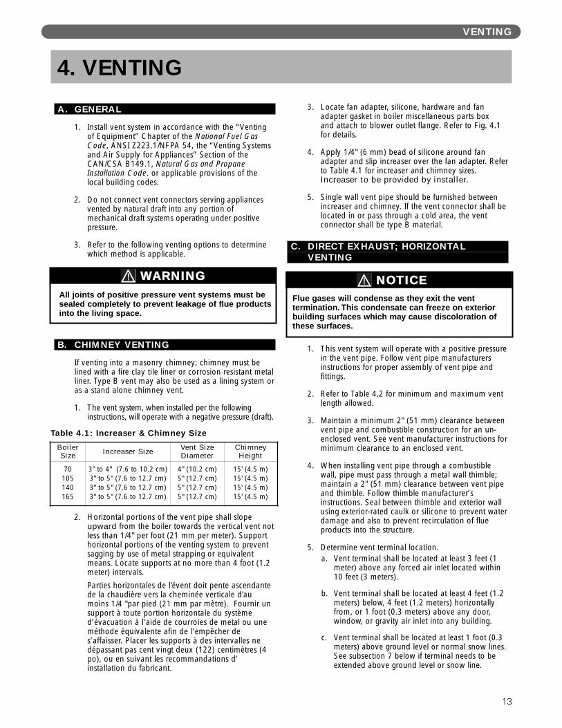
4. Apply 1/4" (6 mm) bead of silicone around fanadapter and slip increaser over the fan adapter. Referto Table 4.1 for increaser and chimney sizes.Increaser to be provided by installer.
5. Single wall vent pipe should be furnished betweenincreaser and chimney. If the vent connector shall belocated in or pass through a cold area, the ventconnector shall be type B material.
C. DIRECT EXHAUST; HORIZONTALVENTING
1. This vent system will operate with a positive pressurein the vent pipe. Follow vent pipe manufacturersinstructions for proper assembly of vent pipe andfittings.
2. Refer to Table 4.2 for minimum and maximum ventlength allowed.
3. Maintain a minimum 2" (51 mm) clearance betweenvent pipe and combustible construction for an un-enclosed vent. See vent manufacturer instructions forminimum clearance to an enclosed vent.
4. When installing vent pipe through a combustiblewall, pipe must pass through a metal wall thimble;maintain a 2" (51 mm) clearance between vent pipeand thimble. Follow thimble manufacturer’sinstructions. Seal between thimble and exterior wallusing exterior-rated caulk or silicone to prevent waterdamage and also to prevent recirculation of flueproducts into the structure.
5. Determine vent terminal location.a. Vent terminal shall be located at least 3 feet (1
meter) above any forced air inlet located within10 feet (3 meters).
b. Vent terminal shall be located at least 4 feet (1.2meters) below, 4 feet (1.2 meters) horizontallyfrom, or 1 foot (0.3 meters) above any door,window, or gravity air inlet into any building.
c. Vent terminal shall be located at least 1 foot (0.3meters) above ground level or normal snow lines.See subsection 7 below if terminal needs to beextended above ground level or snow line.
4. VENTING
Table 4.1: Increaser & Chimney Size
BoilerSize Increaser Size Vent Size
DiameterChimney Height
70105140165
3" to 4" (7.6 to 10.2 cm)3" to 5" (7.6 to 12.7 cm)3" to 5" (7.6 to 12.7 cm)3" to 5" (7.6 to 12.7 cm)
4" (10.2 cm)5" (12.7 cm)5" (12.7 cm)5" (12.7 cm)
15' (4.5 m)15' (4.5 m)15' (4.5 m)15' (4.5 m)
All joints of positive pressure vent systems must besealed completely to prevent leakage of flue productsinto the living space.
WARNING
Flue gases will condense as they exit the venttermination. This condensate can freeze on exteriorbuilding surfaces which may cause discoloration ofthese surfaces.
NOTICE

d. Vent terminal shall not be located over publicwalkways where condensate could create anuisance or hazard.
e. When adjacent to a public walkway, ventterminal shall be at least 7 feet (2.1 meters)above grade.
f. Vent terminal shall be located at least 4 feet (1.2meters) horizontally from electric meters, gasmeters, regulators and relief equipment. InCanada, this dimension must be 6 feet (2 meters).
g. Vent terminal should not be located directlyunder roof overhangs to prevent icicles fromforming.
6. Vent Pipe Assembly:a. Horizontal portions of the vent pipe shall slope
downward from the boiler to the venttermination elbow, not less than 1/4" per foot(21 mm per meter). If any horizontal portions ofthe vent pipe instead slope toward boiler, providea horizontal drain tee as per instructions insection D. Direct Exhaust; Vertical Venting.
Parties horizontales de l'évent doit s'incliner versle bas de la chaudière à la terminaison deventilation (coude), pas moins de 1/4 "par pied(21 mm par mètre).
Si les parties horizontales de l'évent au lieu pentevers la chaudière, prévoir un tee drain horizontalen suivant les instructions de la section D.échappement direct, évacuation verticale.
b. Support horizontal portions of the venting systemto prevent sagging by use of metal strapping orequivalent means. Do not screw into the vent pipe.
Fournir un support à toute portion horizontale dusystème d’évacuation à l’aide de courroies demetal ou une méthode équivalente afin del’empêcher de s’affaisser. Ne pas visser dans letuyau de ventilation.
• Horizontal portions of the vent pipe must besupported at intervals no greater than fourfeet to prevent sagging/separation.
Parties horizontales du conduit d'évacuationdoit être soutenu à intervalles ne dépassantpas quatre pieds pour éviter tout affaissement /séparation.
• Secure vent pipe to the thimble/wall toprevent possible movement from incidentalcontact on the vent terminal.
c. Type vent material approved is AL29-4C, 3 inch(76 mm) diameter stainless steel; manufacturedby Heat-Fab® (Saf-T-Vent); Z-Flex® (Z-Vent);ProTech (FasNSeal™); Flex-L (StaR-34); Metal-Fab (Corr/Guard).
d. Attach the fan adapter to blower outlet flangeusing gasket and 1/4" (6 mm) -20 nuts andwashers, (parts located in miscellaneous partsbox).
e. Refer to Figure 4.3 that lists special vent adaptersfor connection to boiler fan adapter. Thesespecial adapters are not supplied with boiler.
f. Attach vent pipe adapter to boiler fan adapter byapplying a 1/4" (6 mm) bead of high temperaturesilicone around diameter of fan adapter and slipvent pipe adapter over the fan adapter. Fill inany voids with silicone and smooth out withmoistened finger or flat tool.
g. If using Z-Flex® pipe, slide vent pipe over the first 2-1/2" (64 mm) of the fan adapter and securejoint connection with the Z-Flex® looking bandsmaking sure that locking band has contact withfan adapter at boiler end and vent pipe.
h. Attach remaining pipe and fittings permanufacturer’s vent instructions. Use only thesilicone recommended by the vent pipemanufacturer.
Figure 4.1: Chimney Venting
VENTING
14
VENTING
15
i. The only approved vent termination is a 3" (76mm) 90° elbow. Refer to Figure 4.4. Vent pipemust be sealed to the thimble (or outside wall if-non-combustible construction) using silicone toprevent recirculation of flue products into thestructure.
*Maximum Vent Length to be reduced by 5 feet (1.5meters) for each 90° elbow added that ismanufactured by Z-Flex®, Heat-Fab® and Protech.
*Maximum Vent Length to be reduced by 7-1/2 feet(2.3 meters) for each 90° elbow added that ismanufactured by Flex-L.
The outside vent terminal (90° Elbow) is notincluded in Equivalent Vent Length.
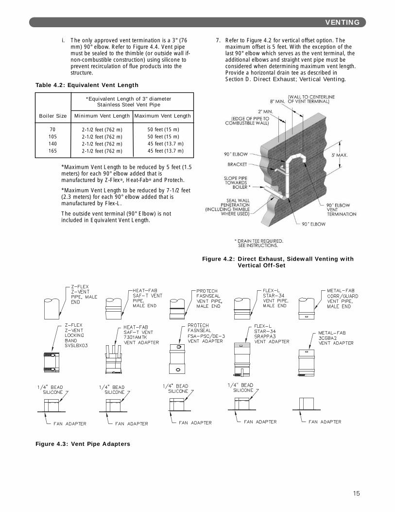
7. Refer to Figure 4.2 for vertical offset option. Themaximum offset is 5 feet. With the exception of thelast 90° elbow which serves as the vent terminal, theadditional elbows and straight vent pipe must beconsidered when determining maximum vent length.Provide a horizontal drain tee as described inSection D. Direct Exhaust; Vertical Venting.
Figure 4.2: Direct Exhaust, Sidewall Venting withVertical Off-Set
Figure 4.3: Vent Pipe Adapters
50 feet (15 m)50 feet (15 m)45 feet (13.7 m)45 feet (13.7 m)
70105140165
Boiler Size
2-1/2 feet (762 m)2-1/2 feet (762 m)2-1/2 feet (762 m)2-1/2 feet (762 m)
Table 4.2: Equivalent Vent Length
*Equivalent Length of 3" diameterStainless Steel Vent Pipe
Minimum Vent Length Maximum Vent Length
16
VENTING
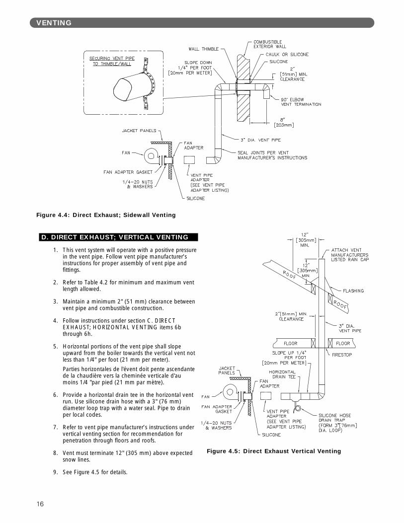
Figure 4.4: Direct Exhaust; Sidewall Venting
D. DIRECT EXHAUST; VERTICAL VENTING
1. This vent system will operate with a positive pressurein the vent pipe. Follow vent pipe manufacturer’sinstructions for proper assembly of vent pipe andfittings.
2. Refer to Table 4.2 for minimum and maximum ventlength allowed.
3. Maintain a minimum 2" (51 mm) clearance betweenvent pipe and combustible construction.
4. Follow instructions under section C. DIRECTEXHAUST; HORIZONTAL VENTING items 6bthrough 6h.
5. Horizontal portions of the vent pipe shall slopeupward from the boiler towards the vertical vent notless than 1/4" per foot (21 mm per meter).
Parties horizontales de l'évent doit pente ascendantede la chaudière vers la cheminée verticale d'aumoins 1/4 "par pied (21 mm par mètre).
6. Provide a horizontal drain tee in the horizontal ventrun. Use silicone drain hose with a 3" (76 mm)diameter loop trap with a water seal. Pipe to drainper local codes.
7. Refer to vent pipe manufacturer’s instructions undervertical venting section for recommendation forpenetration through floors and roofs.
8. Vent must terminate 12" (305 mm) above expectedsnow lines.
9. See Figure 4.5 for details.
Figure 4.5: Direct Exhaust Vertical Venting
17
VENTING
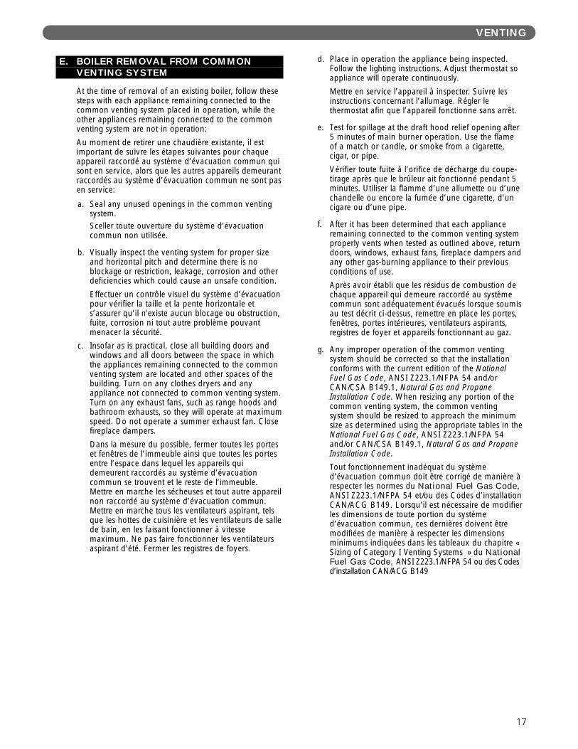
E. BOILER REMOVAL FROM COMMONVENTING SYSTEM
At the time of removal of an existing boiler, follow thesesteps with each appliance remaining connected to thecommon venting system placed in operation, while theother appliances remaining connected to the commonventing system are not in operation:
Au moment de retirer une chaudière existante, il estimportant de suivre les étapes suivantes pour chaqueappareil raccordé au système d’évacuation commun quisont en service, alors que les autres appareils demeurantraccordés au système d’évacuation commun ne sont pasen service:
a. Seal any unused openings in the common ventingsystem.Sceller toute ouverture du système d’évacuationcommun non utilisée.
b. Visually inspect the venting system for proper sizeand horizontal pitch and determine there is noblockage or restriction, leakage, corrosion and otherdeficiencies which could cause an unsafe condition.
Effectuer un contrôle visuel du système d’évacuationpour vérifier la taille et la pente horizontale ets’assurer qu’il n’existe aucun blocage ou obstruction,fuite, corrosion ni tout autre problème pouvantmenacer la sécurité.
c. Insofar as is practical, close all building doors andwindows and all doors between the space in whichthe appliances remaining connected to the commonventing system are located and other spaces of thebuilding. Turn on any clothes dryers and anyappliance not connected to common venting system.Turn on any exhaust fans, such as range hoods andbathroom exhausts, so they will operate at maximumspeed. Do not operate a summer exhaust fan. Closefireplace dampers.
Dans la mesure du possible, fermer toutes les porteset fenêtres de l’immeuble ainsi que toutes les portesentre l’espace dans lequel les appareils quidemeurent raccordés au système d’évacuationcommun se trouvent et le reste de l’immeuble.Mettre en marche les sécheuses et tout autre appareilnon raccordé au système d’évacuation commun.Mettre en marche tous les ventilateurs aspirant, telsque les hottes de cuisinière et les ventilateurs de sallede bain, en les faisant fonctionner à vitessemaximum. Ne pas faire fonctionner les ventilateursaspirant d’été. Fermer les registres de foyers.
d. Place in operation the appliance being inspected.Follow the lighting instructions. Adjust thermostat soappliance will operate continuously.
Mettre en service l’appareil à inspecter. Suivre lesinstructions concernant l’allumage. Régler lethermostat afin que l’appareil fonctionne sans arrêt.
e. Test for spillage at the draft hood relief opening after5 minutes of main burner operation. Use the flameof a match or candle, or smoke from a cigarette,cigar, or pipe.
Vérifier toute fuite à l’orifice de décharge du coupe-tirage après que le brûleur ait fonctionné pendant 5minutes. Utiliser la flamme d’une allumette ou d’unechandelle ou encore la fumée d’une cigarette, d’uncigare ou d’une pipe.
f. After it has been determined that each applianceremaining connected to the common venting systemproperly vents when tested as outlined above, returndoors, windows, exhaust fans, fireplace dampers andany other gas-burning appliance to their previousconditions of use.
Après avoir établi que les résidus de combustion dechaque appareil qui demeure raccordé au systèmecommun sont adéquatement évacués lorsque soumisau test décrit ci-dessus, remettre en place les portes,fenêtres, portes intérieures, ventilateurs aspirants,registres de foyer et appareils fonctionnant au gaz.
g. Any improper operation of the common ventingsystem should be corrected so that the installationconforms with the current edition of the NationalFuel Gas Code, ANSI Z223.1/NFPA 54 and/orCAN/CSA B149.1, Natural Gas and PropaneInstallation Code. When resizing any portion of thecommon venting system, the common ventingsystem should be resized to approach the minimumsize as determined using the appropriate tables in theNational Fuel Gas Code, ANSI Z223.1/NFPA 54and/or CAN/CSA B149.1, Natural Gas and PropaneInstallation Code.
Tout fonctionnement inadéquat du systèmed’évacuation commun doit être corrigé de manière àrespecter les normes du National Fuel Gas Code,ANSI Z223.1/NFPA 54 et/ou des Codes d’installationCAN/ACG B149. Lorsqu’il est nécessaire de modifierles dimensions de toute portion du systèmed’évacuation commun, ces dernières doivent êtremodifiées de manière à respecter les dimensionsminimums indiquées dans les tableaux du chapitre «Sizing of Category I Venting Systems » du NationalFuel Gas Code, ANSI Z223.1/NFPA 54 ou des Codesd’installation CAN/ACG B149

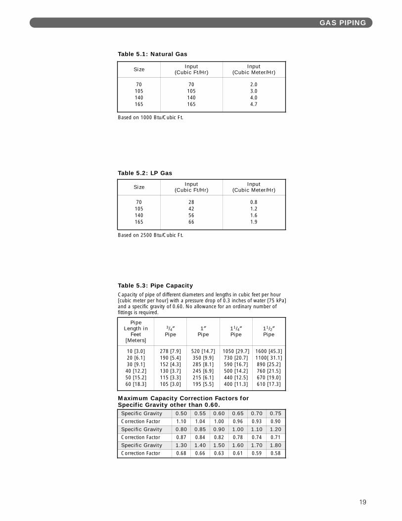
1. Size and install the gas supply piping properly inorder to provide a supply of gas sufficient to meetthe maximum demand without undue loss ofpressure between the meter and the boiler.
2. Determine the volume of gas to be provided to theboiler in cubic feet per hour. To obtain this value,divide the Btu per hour rating (on the boiler ratingplate) by the heating value of the gas in Btu percubic feet. Obtain the heating value of the gas fromthe gas supplier. As an alternative, use Table 5.1 or5.2 on the next page to obtain the volume of gas tobe provided to the boiler.
3. Use the value obtained above as the basis for pipingsizing. Size the gas piping in accordance with Table5.3. Consult the National Fuel Gas Code ANSIZ223.1/NFPA 54 and or CAN/CSA B149.1, NaturalGas and Propane Installation Code for proper sizingoptions.
4. Locate the drop pipe adjacent to, but not in front ofthe boiler.
5. Install a sediment trap. See Figure 5.1. Locate a teein the drop pipe at same elevation as the gas inletconnection to the boiler. Extend the drop pipe to apipe cap.
6. Install a ground joint union ahead of the gas controlassembly to permit servicing of the control. Somelocal codes require an additional service valve whenusing the combination gas controls. If your coderequires such a valve, a suggested location is shownin Figure 5.1.
7. Check piping for leaks.
Use an approved gas detector, a non-corrosive leakdetection fluid or other leak detection method. Ifleaks are found, turn off all gas flow and repair asnecessary.
8. Disconnect the boiler and its individual shut-off valvefrom the gas supply piping system during anypressure testing of that system at test pressure inexcess of 1/2 psig (3.5 kPa).
Isolate the boiler from the gas supply piping systemby closing its individual service valve during anypressure testing of the gas supply piping system attest pressure equal to or less than 1/2 psig (3.5 kPa).
9. Minimum permissible supply pressure for purposes ofinput adjustment:
Natural Gas 5.0″ W.C. (1.2 kPa)LP Gas 11.0″ W.C. (2.7 kPa)
Maximum permissible supply pressure to the boiler(Inches Water Column):
Natural Gas 13.5″ W.C. (3.4 kPa)LP Gas 13.5″ W.C. (3.4 kPa)
5. GAS PIPING
Figure 5.1: Gas Connection to Boiler
When checking for leaks, do not use matches,candles, open flames or other methods that provide asource of ignition. This can ignite a gas leak,resulting in fire or explosion.
WARNING
Use a pipe joint sealing compound that is resistant tothe action of liquefied petroleum gas. A non-resistantcompound may lose sealing ability in the presence ofthis gas, resulting in a gas leak and fire or explosionpotential.
WARNING
Do not subject the gas valve to more than 1/2 psi (3.5 kPa) pressure. Doing so may damage the valve.
CAUTION
GAS PIPING
18
GAS PIPING
19
Table 5.3: Pipe CapacityCapacity of pipe of different diameters and lengths in cubic feet per hour[cubic meter per hour] with a pressure drop of 0.3 inches of water [75 kPa]and a specific gravity of 0.60. No allowance for an ordinary number of fittings is required.
Table 5.1: Natural Gas
Based on 1000 Btu/Cubic Ft.
Table 5.2: LP Gas
Based on 2500 Btu/Cubic Ft.
Size Input(Cubic Ft/Hr)
Input(Cubic Meter/Hr)
70105140165
70105140165
2.03.04.04.7
Size Input(Cubic Ft/Hr)
Input(Cubic Meter/Hr)
70105140165
28425666
0.81.21.61.9
PipeLength in
Feet [Meters]
3/4″Pipe
1″Pipe
11/4″Pipe
11/2″Pipe
10 [3.0]20 [6.1]30 [9.1]
40 [12.2]50 [15.2]60 [18.3]
278 [7.9]190 [5.4]152 [4.3]130 [3.7]115 [3.3]105 [3.0]
520 [14.7]350 [9.9]285 [8.1]245 [6.9]215 [6.1]195 [5.5]
1050 [29.7]730 [20.7]590 [16.7]500 [14.2]440 [12.5]400 [11.3]
1600 [45.3]1100[ 31.1]890 [25.2]760 [21.5]670 [19.0]610 [17.3]
Specific Gravity 0.50 0.55 0.60 0.65 0.70 0.75Correction Factor 1.10 1.04 1.00 0.96 0.93 0.90
Specific Gravity 0.80 0.85 0.90 1.00 1.10 1.20Correction Factor 0.87 0.84 0.82 0.78 0.74 0.71
Specific Gravity 1.30 1.40 1.50 1.60 1.70 1.80Correction Factor 0.68 0.66 0.63 0.61 0.59 0.58
Maximum Capacity Correction Factors forSpecific Gravity other than 0.60.
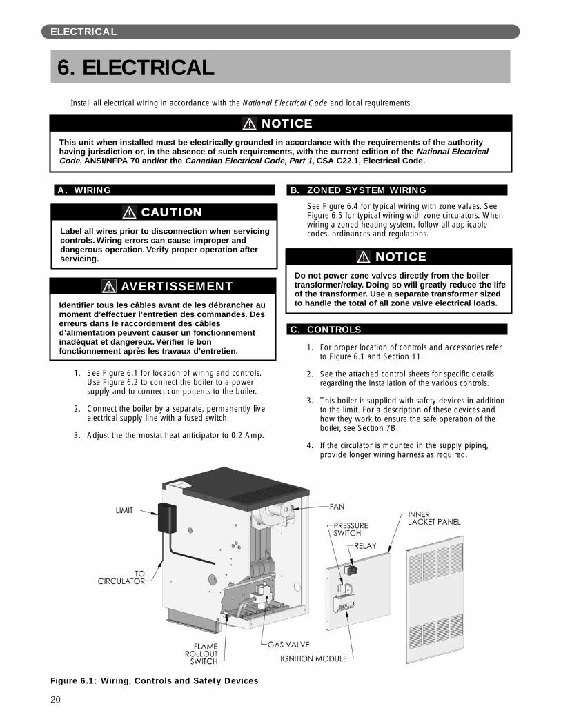
A. WIRING
1. See Figure 6.1 for location of wiring and controls.Use Figure 6.2 to connect the boiler to a powersupply and to connect components to the boiler.
2. Connect the boiler by a separate, permanently liveelectrical supply line with a fused switch.
3. Adjust the thermostat heat anticipator to 0.2 Amp.
B. ZONED SYSTEM WIRING
See Figure 6.4 for typical wiring with zone valves. SeeFigure 6.5 for typical wiring with zone circulators. Whenwiring a zoned heating system, follow all applicablecodes, ordinances and regulations.
C. CONTROLS
1. For proper location of controls and accessories referto Figure 6.1 and Section 11.
2. See the attached control sheets for specific detailsregarding the installation of the various controls.
3. This boiler is supplied with safety devices in additionto the limit. For a description of these devices andhow they work to ensure the safe operation of theboiler, see Section 7B.
4. If the circulator is mounted in the supply piping,provide longer wiring harness as required.
6. ELECTRICAL
This unit when installed must be electrically grounded in accordance with the requirements of the authorityhaving jurisdiction or, in the absence of such requirements, with the current edition of the National ElectricalCode, ANSI/NFPA 70 and/or the Canadian Electrical Code, Part 1, CSA C22.1, Electrical Code.
NOTICE
Figure 6.1: Wiring, Controls and Safety Devices
Install all electrical wiring in accordance with the National Electrical Code and local requirements.
Do not power zone valves directly from the boilertransformer/relay. Doing so will greatly reduce the lifeof the transformer. Use a separate transformer sizedto handle the total of all zone valve electrical loads.
NOTICE
ELECTRICAL
20
Label all wires prior to disconnection when servicingcontrols. Wiring errors can cause improper anddangerous operation. Verify proper operation afterservicing.
CAUTION
Identifier tous les câbles avant de les débrancher aumoment d’effectuer l’entretien des commandes. Deserreurs dans le raccordement des câblesd’alimentation peuvent causer un fonctionnementinadéquat et dangereux. Vérifier le bonfonctionnement après les travaux d’entretien.
AVERTISSEMENT
ELECTRICAL
21
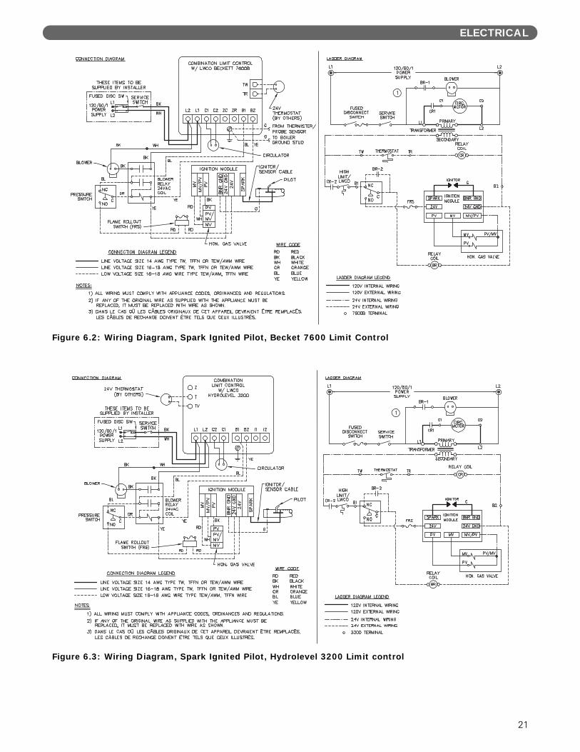
Figure 6.2: Wiring Diagram, Spark Ignited Pilot, Becket 7600 Limit Control
Figure 6.3: Wiring Diagram, Spark Ignited Pilot, Hydrolevel 3200 Limit control
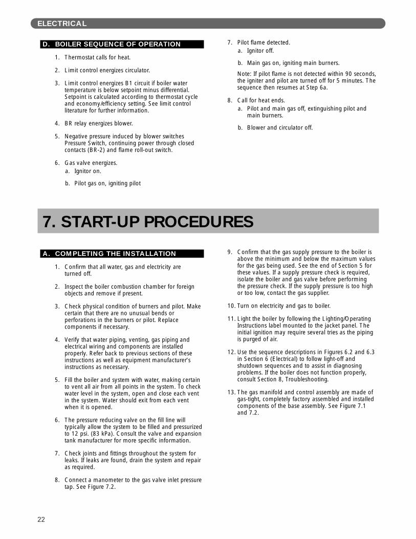
D. BOILER SEQUENCE OF OPERATION
1. Thermostat calls for heat.
2. Limit control energizes circulator.
3. Limit control energizes B1 circuit if boiler watertemperature is below setpoint minus differential.Setpoint is calculated according to thermostat cycleand economy/efficiency setting. See limit controlliterature for further information.
4. BR relay energizes blower.
5. Negative pressure induced by blower switchesPressure Switch, continuing power through closedcontacts (BR-2) and flame roll-out switch.
6. Gas valve energizes.a. Ignitor on.
b. Pilot gas on, igniting pilot
7. Pilot flame detected.a. Ignitor off.
b. Main gas on, igniting main burners.
Note: If pilot flame is not detected within 90 seconds,the igniter and pilot are turned off for 5 minutes. Thesequence then resumes at Step 6a.
8. Call for heat ends.a. Pilot and main gas off, extinguishing pilot and
main burners.
b. Blower and circulator off.
ELECTRICAL
22
A. COMPLETING THE INSTALLATION
1. Confirm that all water, gas and electricity areturned off.
2. Inspect the boiler combustion chamber for foreignobjects and remove if present.
3. Check physical condition of burners and pilot. Makecertain that there are no unusual bends orperforations in the burners or pilot. Replacecomponents if necessary.
4. Verify that water piping, venting, gas piping andelectrical wiring and components are installedproperly. Refer back to previous sections of theseinstructions as well as equipment manufacturer’sinstructions as necessary.
5. Fill the boiler and system with water, making certainto vent all air from all points in the system. To checkwater level in the system, open and close each ventin the system. Water should exit from each ventwhen it is opened.
6. The pressure reducing valve on the fill line willtypically allow the system to be filled and pressurizedto 12 psi. (83 kPa). Consult the valve and expansiontank manufacturer for more specific information.
7. Check joints and fittings throughout the system forleaks. If leaks are found, drain the system and repairas required.
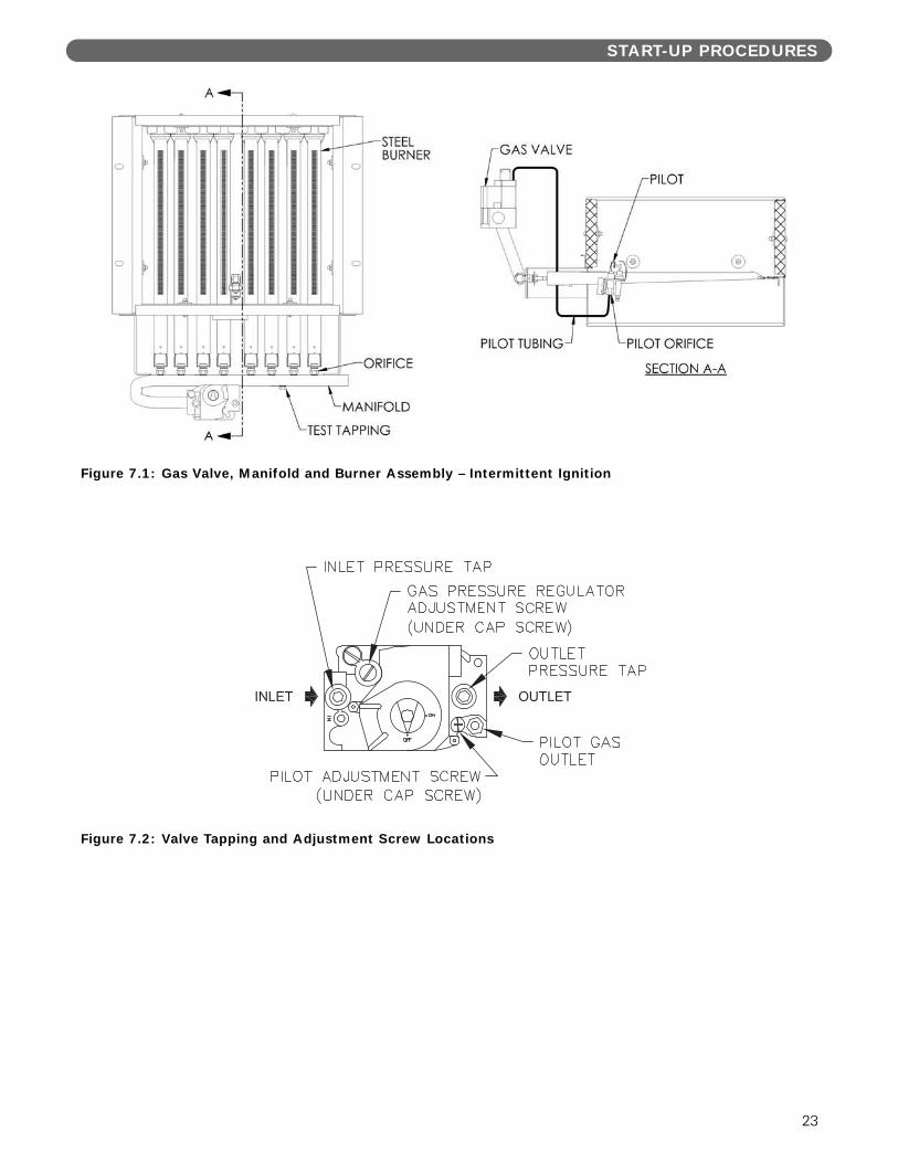
8. Connect a manometer to the gas valve inlet pressuretap. See Figure 7.2.
9. Confirm that the gas supply pressure to the boiler isabove the minimum and below the maximum valuesfor the gas being used. See the end of Section 5 forthese values. If a supply pressure check is required,isolate the boiler and gas valve before performingthe pressure check. If the supply pressure is too highor too low, contact the gas supplier.
10. Turn on electricity and gas to boiler.
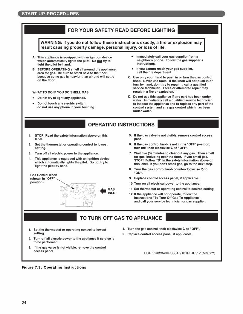
11. Light the boiler by following the Lighting/OperatingInstructions label mounted to the jacket panel. Theinitial ignition may require several tries as the pipingis purged of air.
12. Use the sequence descriptions in Figures 6.2 and 6.3in Section 6 (Electrical) to follow light-off andshutdown sequences and to assist in diagnosingproblems. If the boiler does not function properly,consult Section 8, Troubleshooting.
13. The gas manifold and control assembly are made ofgas-tight, completely factory assembled and installedcomponents of the base assembly. See Figure 7.1and 7.2.
7. START-UP PROCEDURES
START-UP PROCEDURES
23
Figure 7.1: Gas Valve, Manifold and Burner Assembly – Intermittent Ignition
Figure 7.2: Valve Tapping and Adjustment Screw Locations
START-UP PROCEDURES
Figure 7.3: Operating Instructions
24

25
Figure 7.4: Operating Instructions
START-UP PROCEDURES

26
B. CONTROL DESCRIPTIONSSee Figure 6.1 in Section 6 (Electrical) for locations ofthese devices.
1. FLAME ROLL-OUT SAFETY SHUT-OFF SWITCH(FLAME ROLL-OUT SWITCH) – A thermallyactivated switch located between the first burnerfrom the left and the manifold bracket. The flameroll-out safety shut-off switch will sense excessivetemperature caused by continued flame roll-out andshut down main burner gas. This is a non-recyclingswitch that must be replaced once it has beenactivated and the cause of the roll-out eliminated.
2. PRESSURE SWITCH – A pressure sensing devicethat is located in the jacket vestibule. This controlsenses a suction pressure when fan is energized on acall for heat. Switch contacts close allowing controlcircuit to energize ignition system.
3. LIMIT (AQUASTAT) – A thermally activated,manually adjustable switch located on the left side ofthe boiler, towards the top and rear. The temperaturesensing element is placed in the supply and will shutdown main burner gas if the supply water exceedsthe preset temperature limit. This is a recycling switchthat will automatically reset when the supply waterfalls below the preset temperature.
4. LOW WATER CUT-OFF (FOR GRAVITY SYSTEMSOR HOT WATER BOILERS INSTALLED ABOVERADIATION LEVEL) – A level-sensing device (floator probe) located in supply piping near the boiler. Ifwater level in the system drops below the control’sposition, it will shut down main burner gas. Thecontrol will automatically reset once the water levelrises above its position.
C. ADJUSTMENT OF GAS PRESSUREREGULATOR
1. Connect a manometer to 1/8 N.P.T. tapping on gasmanifold, set manifold pressure as follows for variousgases.a. Natural Gas . . . . . . . . . .3.5″ W.C. (0.9 kPa)
b. LP Gas . . . . . . . . . . . . .10.0″ W.C. (2.5 kPa)
2. To adjust gas pressure, turn adjusting screw of gaspressure regulator counterclockwise to decreasepressure, clockwise to increase pressure. Refer toFigure 7.2 for location of gas pressure regulator.Replace the cap screw when adjustment is complete.
3. In no case should the final manifold pressure varymore than ±0.3 inches water column (0.07 kPa)from the above specified pressures. Any necessarymajor changes in the flow should be made bychanging the size of the burner orifice spuds.
4. When adjustment is complete, turn off boiler, gasflow and electricity to boiler. Remove manometerconnection from valve and plug tapping with plugprovided. Turn utilities back on and resumecheckout.
D. CHECKING BURNER INPUT
1. Refer to rating label mounted on the jacket top panelto obtain the rated BTU per hour input. In no caseshall the input to the boiler exceed the value shownon the rating label.
2. Check input by use of the following formula (suggest reading meter for 2 Cu.Ft. [0.0566 cubicmeter]):
U.S. Customary Units:Input (BTU/Hr.)= 3600 x F x H
TWhere:3600 – Seconds per hour
F – Cubic Feet of Gas Registered on MeterH – Heat Value of Gas in BTU/Cubic FeetT – Time in Seconds the Meter is Read
SI Metric UnitsInput (kW)= 3600 x F x H
T x 3.6Where:3600 – Seconds per hour
3.6 – Megajoule (MJ) per kilowatt hour (kwhr)F – Cubic Meters of Gas Registered on MeterH – Heating Value of Gas in MJ/Cubic MeterT – Time in Seconds the Meter is Read
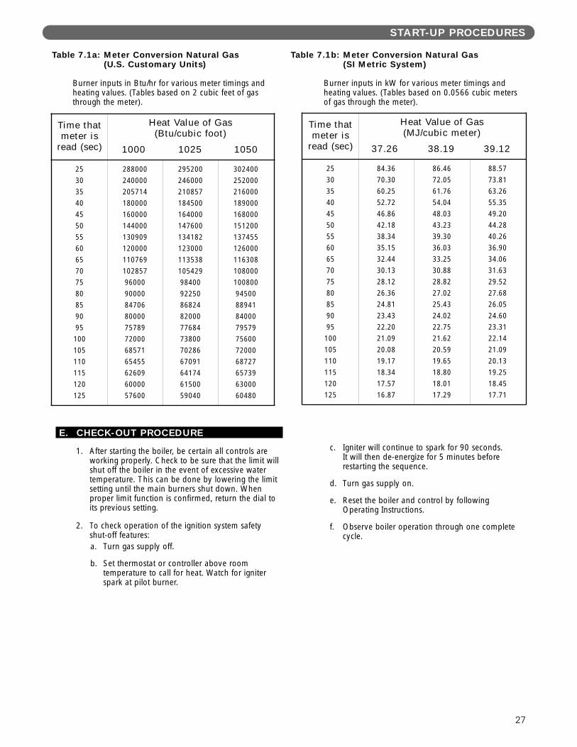
3. As an alternative, use Table 7.1a and 7.1b. Use theheating value provided by gas supplier. Use astopwatch to record the time it takes for 2 cubic feet(0.0566 cubic meter) of gas to pass through themeter. Read across and down to determine rate.
START-UP PROCEDURES
27
E. CHECK-OUT PROCEDURE
1. After starting the boiler, be certain all controls areworking properly. Check to be sure that the limit willshut off the boiler in the event of excessive watertemperature. This can be done by lowering the limitsetting until the main burners shut down. Whenproper limit function is confirmed, return the dial toits previous setting.
2. To check operation of the ignition system safetyshut-off features:a. Turn gas supply off.
b. Set thermostat or controller above roomtemperature to call for heat. Watch for igniterspark at pilot burner.
c. Igniter will continue to spark for 90 seconds. It will then de-energize for 5 minutes beforerestarting the sequence.
d. Turn gas supply on.
e. Reset the boiler and control by followingOperating Instructions.
f. Observe boiler operation through one completecycle.
START-UP PROCEDURES
Table 7.1a: Meter Conversion Natural Gas (U.S. Customary Units)
Table 7.1b: Meter Conversion Natural Gas (SI Metric System)
Burner inputs in kW for various meter timings andheating values. (Tables based on 0.0566 cubic metersof gas through the meter).
Burner inputs in Btu/hr for various meter timings andheating values. (Tables based on 2 cubic feet of gasthrough the meter).
Time thatmeter is
read (sec)
Heat Value of Gas(MJ/cubic meter)
37.26 38.19 39.12
253035404550556065707580859095
100105110115120125
84.3670.3060.2552.7246.8642.1838.3435.1532.4430.1328.1226.3624.8123.4322.2021.0920.0819.1718.3417.5716.87
86.4672.0561.7654.0448.0343.2339.3036.0333.2530.8828.8227.0225.4324.0222.7521.6220.5919.6518.8018.0117.29
88.5773.8163.2655.3549.2044.2840.2636.9034.0631.6329.5227.6826.0524.6023.3122.1421.0920.1319.2518.4517.71
Time thatmeter is
read (sec)
Heat Value of Gas(Btu/cubic foot)
1000 1025 1050
253035404550556065707580859095
100105110115120125
2880002400002057141800001600001440001309091200001107691028579600090000847068000075789720006857165455626096000057600
2952002460002108571845001640001476001341821230001135381054299840092250868248200077684738007028667091641746150059040
30240025200021600018900016800015120013745512600011630810800010080094500889418400079579756007200068727657396300060480
28
3. Low Water Cut-Off (if used) – Consult themanufacturer’s instructions for the low water cut-offoperational check procedure.
4. Check the system to make sure there are no leaks oroverfilling problems which might cause excessivemake-up water to be added. Make-up water causesliming in the boiler and brings in oxygen. Oxygencan cause severe damage to the boiler throughoxygen corrosion pitting.
5. Check the expansion tank and automatic fill valve (ifused) to confirm that they are operating correctly. Ifeither of these components causes high pressure inthe system, the boiler relief valve will weep or open,allowing fresh water to enter the system.
6. Do not allow the system controls to subject the boilerto excessively low water temperatures, which wouldcause condensation of flue gases and corrosion ofthe boiler. Operate the boiler at a temperature above130°F (55°C). Adjust the boiler limit as required tomaintain boiler temperature above this level.
7. Check the general condition of the system includingpiping support, joints, etc. Check cleanliness of theradiators, baseboard units and/or convectors. Cleanthem to the extent possible. If radiators do not heatevenly, vent any remaining air from them.
8. Review operation and User’s Information Manualwith end-user.
9. Hang the Installation, Operation and MaintenanceManual and User’s Information Manual in anaccessible position near the boiler.
START-UP PROCEDURES
29
A. SHUT-DOWN CAUSED BY PILOT OUTAGE, PRESSURE SWITCH ORFLAME ROLL-OUT SAFETY SHUT-OFF SWITCHIn the event of a shut-down caused by a pilot outage,action of the pressure switch or flame roll-out safetyshut-off switch effecting a shut-down of the mainburners:
a. Refer to the Operating Instructions in Figure 7.3 toproperly turn off the gas to the boiler.
b. Turn off all electric power to the boiler.c. Call a qualified heating service organization or local
gas company and have the cause of the shut-downinvestigated and corrected.
d. Refer to Operating Instructions tore-start boiler.
B. TROUBLESHOOTING GUIDES
Use Table 8.2 to assist in determining causes andproviding corrective actions to boiler problems. Referalso to Figure 8.2 to troubleshoot the IntermittentIgnition System Control. These guides must be usedonly by qualified service technicians. These individualsmust follow all applicable codes and regulations in repairof any boiler problems.
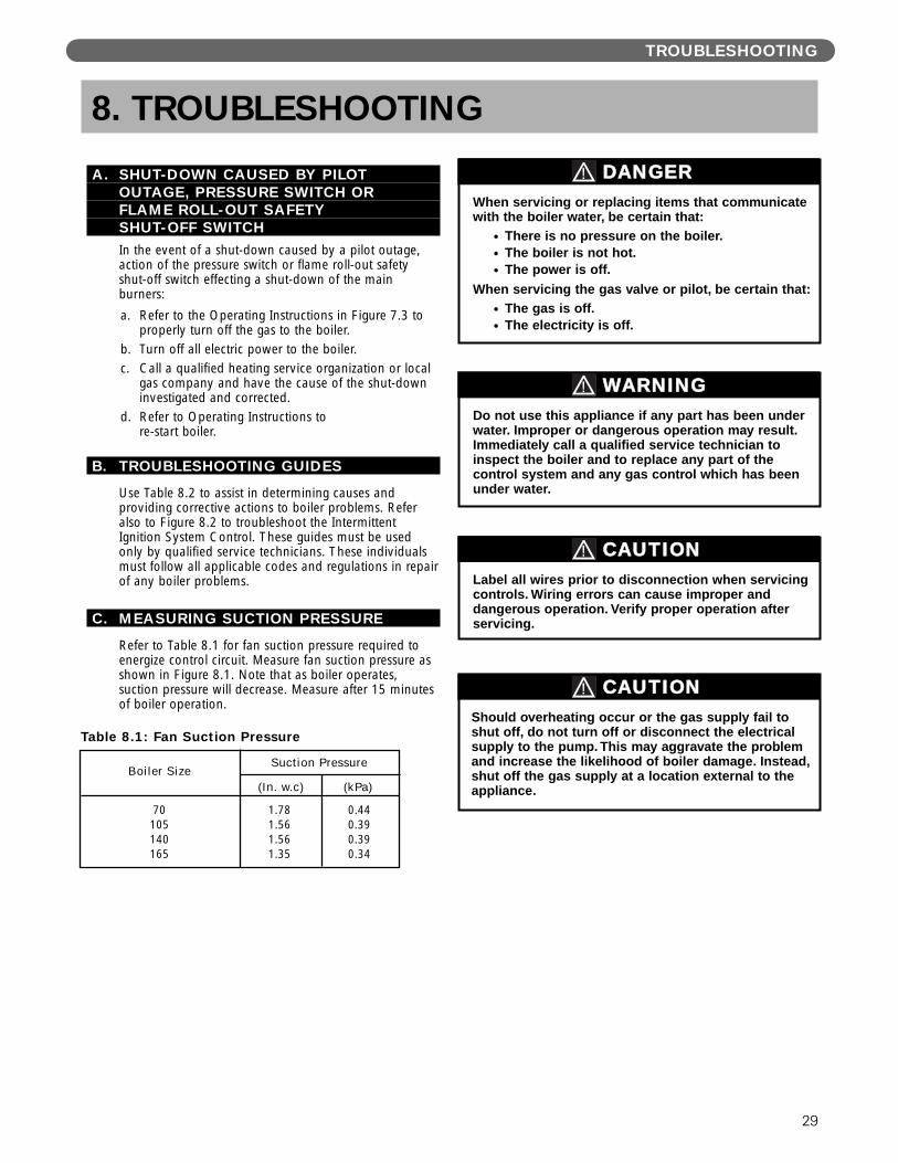
C. MEASURING SUCTION PRESSURE
Refer to Table 8.1 for fan suction pressure required toenergize control circuit. Measure fan suction pressure asshown in Figure 8.1. Note that as boiler operates,suction pressure will decrease. Measure after 15 minutesof boiler operation.
TROUBLESHOOTING
8. TROUBLESHOOTING
Should overheating occur or the gas supply fail toshut off, do not turn off or disconnect the electricalsupply to the pump. This may aggravate the problemand increase the likelihood of boiler damage. Instead,shut off the gas supply at a location external to theappliance.
CAUTION
Do not use this appliance if any part has been underwater. Improper or dangerous operation may result.Immediately call a qualified service technician toinspect the boiler and to replace any part of thecontrol system and any gas control which has beenunder water.
WARNING
Label all wires prior to disconnection when servicingcontrols. Wiring errors can cause improper anddangerous operation. Verify proper operation afterservicing.
CAUTION
When servicing or replacing items that communicatewith the boiler water, be certain that:
● There is no pressure on the boiler.● The boiler is not hot.● The power is off.
When servicing the gas valve or pilot, be certain that:● The gas is off.● The electricity is off.
DANGER
Table 8.1: Fan Suction Pressure
70105140165
Boiler SizeSuction Pressure
1.781.561.561.35
0.440.390.390.34
(In. w.c) (kPa)
30
TROUBLESHOOTING
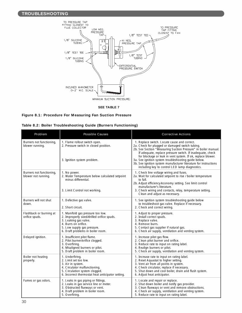
Figure 8.1: Procedure For Measuring Fan Suction Pressure
SEE TABLE 7
Table 8.2: Boiler Troubleshooting Guide (Burners Functioning)
Problem Possible Causes Corrective Actions
Burners not functioning,blower running.
1. Flame rollout switch open.2. Pressure switch in closed position.
3. Ignition system problem.
1. Replace switch. Locate cause and correct.2a. Check for plugged or damaged switch tubing.2b. See Section “Measuring Suction Pressure” in boiler manual.
If adequate, replace pressure switch. If inadequate, check for blockage or leak in vent system. If ok, replace blower.
3a. See ignition system troubleshooting guide below.3b. See ignition system manufacturer literature for instructions
including key to control LED lamp diagnostics.
Burners not functioning,blower not running.
1. No power.2. Water Temperature below calculated setpoint
minus differential.
3. Limit Control not working.
1. Check line voltage wiring and fuses.2a. Wait for calculated setpoint to rise / boiler temperature
to fall.2b. Adjust efficiency/economy setting. See limit control
manufacturer’s literature.3. Check wiring and contacts, relay, temperature setting.
Clean and adjust as necessary.
Burners will not shutdown.
1. Defective gas valve.
2. Short circuit.
1. See ignition system troubleshooting guide below to troubleshoot gas valve. Replace if necessary.
2. Check and correct wiring.
Flashback or burning atorifice spuds.
1. Manifold gas pressure too low.2. Improperly sized/drilled orifice spuds.3. Leaking gas valve.4. Burrs on orifice.5. Low supply gas pressure.6. Draft problems in boiler room.
1. Adjust to proper pressure.2. Install correct spuds.3. Replace valve.4. Remove burrs.5. Contact gas supplier if natural gas.6. Check air supply, ventilation and venting system.
Delayed ignition. 1. Insufficient pilot flame.2. Pilot burner/orifice clogged.3. Overfiring.4. Misaligned burners or pilot.5. Draft problem in boiler room.
1. Increase pilot gas flow.2. Clean pilot burner and orifice.3. Reduce rate to input on rating label.4. Realign burners or pilot.5. Check air supply, ventilation and venting system.
Boiler not heating properly.
1. Underfiring.2. Limit set too low.3. Air in system.4. Circulator malfunctioning.5. Circulation system clogged.6. Incorrect thermostat heat anticipator setting.
1. Increase rate to input on rating label.2. Reset Aquastat to higher setting.3. Vent air from all points in system.4. Check circulator, replace if necessary.5. Shut down and cool boiler, drain and flush system.6. Adjust heat anticipator.
Fumes or gas odors. 1. Leaks in gas piping or fittings.2. Leaks in gas service line or meter.3. Obstructed flueways or vent.4. Draft problem in boiler room.5. Overfiring.
1. Locate and repair or replace.2. Shut down boiler and notify gas provider.3. Clean flueways or vent and remove obstructions.4. Check air supply, ventilation and venting system.5. Reduce rate to input on rating label.
31
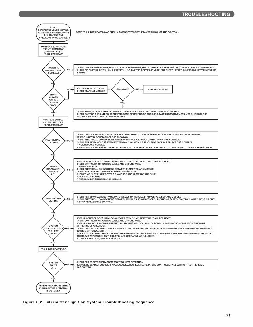
TROUBLESHOOTING
Figure 8.2: Intermittent Ignition System Troubleshooting Sequence
NOTE: “CALL FOR HEAT” 24 VAC SUPPLY IS CONNECTED TO THE 24 V TERMINAL ON THE CONTROL.
TURN GAS SUPPLY OFF,TURN THERMOSTAT(CONTROLLER) TO“CALL FOR HEAT.”
POWER TOMODULE? (24 V
NOMINAL)
SPARKACROSS IGNITER/SENSOR
GAP?
PILOT BURNERLIGHTS?
SPARKSTOPS WHEN
PILOT ISLIT?
SYSTEMSHUTSOFF?
SYSTEMRUNS UNTIL “CALL
FOR HEAT”ENDS?
MAIN BURNERLIGHTS?
TURN GAS SUPPLY ON AND RECYCLE “CALL FOR HEAT.”
“CALL FOR HEAT” ENDS
CHECK LINE VOLTAGE POWER, LOW VOLTAGE TRANSFORMER, LIMIT CONTROLLER, THERMOSTAT (CONTROLLER), AND WIRING ALSO.CHECK AIR PROVING SWITCH ON COMBUSTION AIR BLOWER SYSTEM (IF USED) AND THAT THE VENT DAMPER END SWITCH (IF USED)IS MADE.
CHECK IGNITION CABLE, GROUND WIRING, CERAMIC INSULATOR, AND SPARK GAP ARE CORRECT.CHECK BOOT OF THE IGNITION CABLE FOR SIGNS OF MELTING OR BUCKLING, TAKE PROTECTIVE ACTION TO SHIELD CABLEAND BOOT FROM EXCESSIVE TEMPERATURES.
CHECK THAT ALL MANUAL GAS VALVES ARE OPEN, SUPPLY TUBING AND PRESSURES ARE GOOD, AND PILOT BURNERORIFICE IS NOT BLOCKED (PILOT GAS FLOWING).CHECK ELECTRICAL CONNECTIONS BETWEEN MODULE AND PILOT OPERATOR ON GAS CONTROL.CHECK FOR 24 VAC ACROSS PV-MV/PV TERMINALS ON MODULE. IF VOLTAGE IS OKAY, REPLACE GAS CONTROL. IF NOT, REPLACE MODULE.NOTE: IT MAY BE NECESSARY TO RECYCLE THE ‘CALL FOR HEAT” MORE THAN ONCE TO CLEAR THE PILOT SUPPLY TUBES OF AIR.
NOTE: IF CONTROL GOES INTO LOCKOUT OR RETRY DELAY, RESET THE “CALL FOR HEAT.”CHECK CONTINUITY OF IGNITION CABLE AND GROUND WIRE.CLEAN FLAME ROD.CHECK ELECTRICAL CONNECTIONS BETWEEN FLAME ROD AND MODULE.CHECK FOR CRACKED CERAMIC FLAME ROD INSULATOR.CHECK THAT PILOT FLAME COVERS FLAME ROD AND IS STEADY AND BLUE.ADJUST PILOT FLAME.IF PROBLEM PERSISTS REPLACE MODULE.
CHECK FOR 24 VAC ACROSS PV-MV/PV TERMINALS ON MODULE. IF NO VOLTAGE, REPLACE MODULE.CHECK ELECTRICAL CONNECTIONS BETWEEN MODULE AND GAS CONTROL INCLUDING SAFETY CONTROLS WIRED IN THE CIRCUIT. IF OKAY, REPLACE GAS CONTROL.
NOTE: IF CONTROL GOES INTO LOCKOUT OR RETRY DELAY, RESET THE “CALL FOR HEAT.”CHECK CONTINUITY OF IGNITION CABLE AND GROUND WIRE.NOTE: IF GROUND IS POOR OR ERRATIC, SHUTDOWNS MAY OCCUR OCCASIONALLY EVEN THOUGH OPERATION IS NORMALAT THE TIME OF CHECKOUT.CHECK THAT PILOT FLAME COVERS FLAME ROD AND IS STEADY AND BLUE, PILOT FLAME MUST NOT BE MOVING AROUND DUE TOOUTSIDE AIR FLOWS, ETC.ADJUST PILOT FLAME. CHECK GAS PRESSURE MEETS APPLIANCE SPECIFICATIONS WHILE APPLIANCE MAIN BURNER ON AND ALLOTHER GAS APPLIANCES ON THE SUPPLY ARE OPERATING AT FULL RATE.IF CHECKS ARE OKAY, REPLACE MODULE.
CHECK FOR PROPER THERMOSTAT (CONTROLLER) OPERATION.REMOVE MV LEAD AT MODULE, IF VALVE CLOSES, RECHECK TEMPERATURE CONTROLLER AND WIRING. IF NOT, REPLACEGAS CONTROL.
YES
YES
YES
YES
YES
NO
NO
NO
NO
NO
YES
YES
NO PULL IGNITION LEAD ANDCHECK SPARK AT MODULE.
SPARK OK? NO REPLACE MODULE
YES
STARTBEFORE TROUBLESHOOTING, FAMILIARIZE YOURSELF WITH
THE STARTUP AND CHECKOUT PROCEDURES.
REPEAT PROCEDURE UNTILTROUBLE FREE OPERATION
IS OBTAINED.
NO
32
9. MAINTENANCE
WARNING
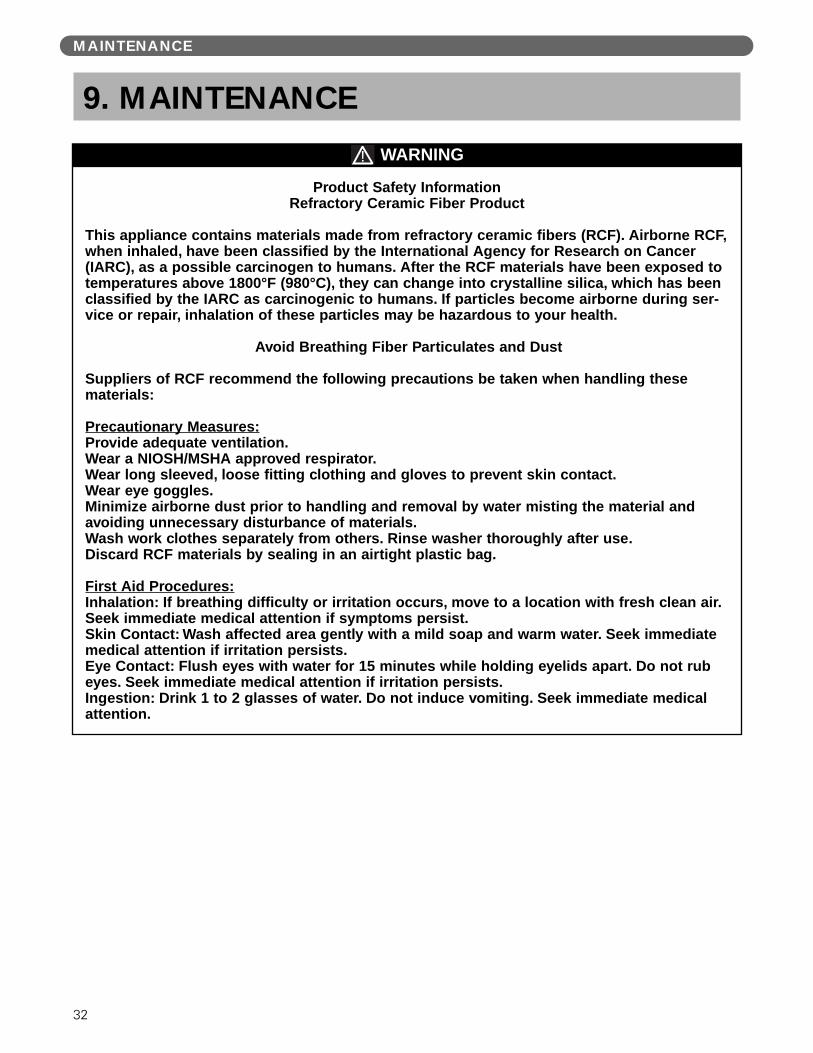
Product Safety InformationRefractory Ceramic Fiber Product
This appliance contains materials made from refractory ceramic fibers (RCF). Airborne RCF,when inhaled, have been classified by the International Agency for Research on Cancer(IARC), as a possible carcinogen to humans. After the RCF materials have been exposed totemperatures above 1800°F (980°C), they can change into crystalline silica, which has beenclassified by the IARC as carcinogenic to humans. If particles become airborne during ser-vice or repair, inhalation of these particles may be hazardous to your health.
Avoid Breathing Fiber Particulates and Dust
Suppliers of RCF recommend the following precautions be taken when handling these materials:
Precautionary Measures:Provide adequate ventilation.Wear a NIOSH/MSHA approved respirator.Wear long sleeved, loose fitting clothing and gloves to prevent skin contact.Wear eye goggles.Minimize airborne dust prior to handling and removal by water misting the material andavoiding unnecessary disturbance of materials. Wash work clothes separately from others. Rinse washer thoroughly after use.Discard RCF materials by sealing in an airtight plastic bag.
First Aid Procedures:Inhalation: If breathing difficulty or irritation occurs, move to a location with fresh clean air.Seek immediate medical attention if symptoms persist.Skin Contact: Wash affected area gently with a mild soap and warm water. Seek immediatemedical attention if irritation persists.Eye Contact: Flush eyes with water for 15 minutes while holding eyelids apart. Do not rubeyes. Seek immediate medical attention if irritation persists.Ingestion: Drink 1 to 2 glasses of water. Do not induce vomiting. Seek immediate medicalattention.
MAINTENANCE

33
MAINTENANCE
A. GENERAL
1. Disconnect this boiler from the gas supply pipingduring any pressure testing of the gas system.
2. Check pipes adjacent to cold walls or in unheatedspaces. Insulate and tape them if necessary to besure they can’t freeze up. Keeping the water movingat all times will reduce the likelihood of freezing. SeeSection 3 for antifreeze instructions.
3. If there is considerable foreign matter in the boilerwater, the boiler should be shut down and allowed tocool, then drained and thoroughly flushed out. Usethe drain valve at the bottom of the returnconnection to drain the boiler. Pipe the drain cock toa suitable drain or containment device if antifreeze isused. Flush the system to remove remaining matter.If there is evidence that hard scale has formed on theinternal surfaces, the boiler should be cleaned bychemical means as prescribed by a qualified watertreatment specialist.
4. There must not be signs of continuous wetness at thechimney. If signs of continuous wetness areobserved, a qualified service agency must beconsulted to modify the vent configuration to preventthe formation of condensate.
B. DAILY (WITH BOILER IN USE)Daily boiler observation can be performed by the owner.If any potential problems are found, a qualified installeror service technician/agency must be notified.
1. Remove any combustible materials, gasoline andother flammable liquids and substances that generateflammable vapors from the area where the boiler iscontained. Make certain that the boiler area hasample air for combustion and ventilation and thatthere are no obstructions to the free flow of air toand from the boiler.
2. Observe general boiler conditions (unusual noises,vibrations, etc.)
3. Observe operating temperature and pressure on thecombination gauge located on the left side of theboiler. Boiler pressure should never be higher than 5 psi (35 kPa) below the rating shown on the safetyrelief valve (25 psig [172 kPa] maximum for a 30psig [207 kPa] rating, 45 psig [310 kPa] maximumfor a 50 psig [345 kPa] rating). The valve rating can be found on the top of the safety relief valve(see Figure 3.1 for location of the safety relief valve).Boiler temperature should never be higher than 250° F (121°C).
4. Check for water leaks in boiler and system piping.
5. Smell around the appliance area for gas. If you smellgas, follow the procedure listed in the OperatingInstructions in Section 7.
C. WEEKLY (WITH BOILER IN USE)
1. Flush float-type low-water cut-off (if used) to removesediment from the float bowl as stated in themanufacturer’s instructions.
D. MONTHLY (WITH BOILER IN USE)
1. Check boiler room floor drains for properfunctioning.
2. Check function of the safety relief valve (monthlyunless specified otherwise by manufacturer) byperforming the following test:a. Check valve piping to determine that it is
properly installed and supported.
b. Check boiler operating temperature and pressure.
c. Lift the try lever on the safety relief valve to thefull open position and hold it for at least fiveseconds or until clean water is discharged.
d. Release the try lever and allow the valve to close.If the valve leaks, operate the lever two or threetimes to clear the valve seat of foreign matter. Itmay take some time to determine if the valve hasshut completely.
e. If the valve continues to leak, it must be replacedbefore the boiler is returned to operation.
f. Check that operating pressure and temperaturehave returned to normal.
g. Check again to confirm that valve has closedcompletely and is not leaking.
3. Test low-water cut-off (if used) as described by themanufacturer.
4. Test limit as described in Section 7E, “Check-OutProcedure.”
5. Test function of gas safety shut-off features asdescribed by gas valve and ignition controlmanufacturer.
34
MAINTENANCE
E. ANNUALLY (BEFORE START OF HEATINGSEASON)
1. Check flueways and burners for cleanliness andclean if necessary. Use the following procedure ifcleaning is required:
a. Refer to the Operating Instructions in Figure 7.3to properly turn off the gas to the boiler.
b. Turn off all electrical power to the boiler.
c. Remove burners and brush gas outlet portslightly using a soft bristle brush.
d. Remove the vent pipe from fan adapter, topjacket panel, flue collector/fan assembly and fluebaffles.
e. Brush flueways with wire brush.
f. To the extent possible, inspect inside of vent pipefor obstructions. Remove or replace as necessary.
g. Re-install baffles. When replacing the fluecollector/fan assembly, be certain that the blanketseal between the flue collector and top sectionmakes a tight seal to prevent leakage of theproducts of combustion.
h. Re-install the top jacket panel and vent pipe.
i. Re-install burners.
2. Inspect entire venting system for corrosion, supportand joint integrity. Repair as necessary. Inspect venttermination for any obstruction that may hinderproper venting.
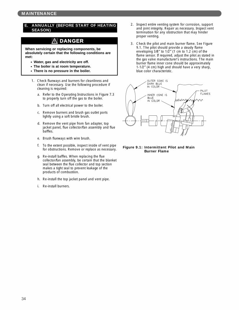
3. Check the pilot and main burner flame. See Figure9.1. The pilot should provide a steady flameenveloping 3/8″ to 1/2″ (1 cm to 1.2 cm) of theflame sensor. If required, adjust the pilot as stated inthe gas valve manufacturer’s instructions. The mainburner flame inner cone should be approximately 1-1/2″ (4 cm) high and should have a very sharp,blue color characteristic.
When servicing or replacing components, beabsolutely certain that the following conditions aremet:
● Water, gas and electricity are off.● The boiler is at room temperature.● There is no pressure in the boiler.
DANGER
Figure 9.1: Intermittent Pilot and MainBurner Flame
35
BOILER DIMENSIONS & RATINGS
10. BOILER DIMENSIONS & RATINGS
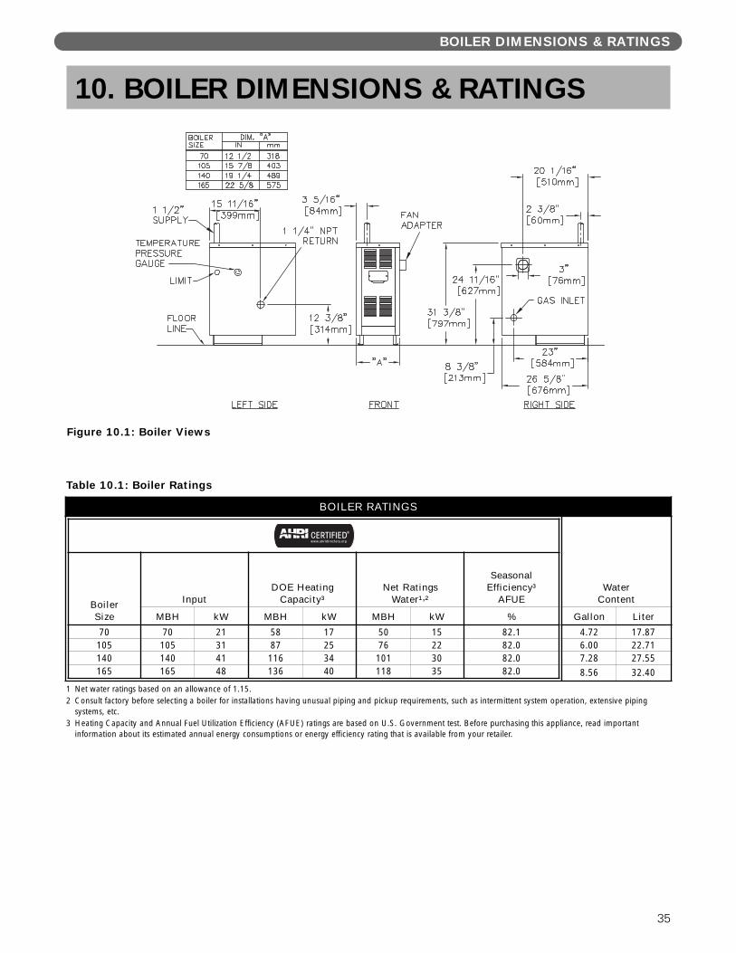
Figure 10.1: Boiler Views
Table 10.1: Boiler Ratings
1 Net water ratings based on an allowance of 1.15.2 Consult factory before selecting a boiler for installations having unusual piping and pickup requirements, such as intermittent system operation, extensive piping
systems, etc.3 Heating Capacity and Annual Fuel Utilization Efficiency (AFUE) ratings are based on U.S. Government test. Before purchasing this appliance, read important
information about its estimated annual energy consumptions or energy efficiency rating that is available from your retailer.
BOILER RATINGS
BoilerSize
InputDOE Heating
Capacity³Net Ratings
Water¹,²
SeasonalEfficiency³
AFUE
MBH kW MBH kW MBH kW %
70 70 21 58 17 50 15 82.1105 105 31 87 25 76 22 82.0140 140 41 116 34 101 30 82.0165 165 48 136 40 118 35 82.0
Water Content
Gallon Liter
4.72 17.876.00 22.717.28 27.558.56 32.40
36
REPAIR PARTS
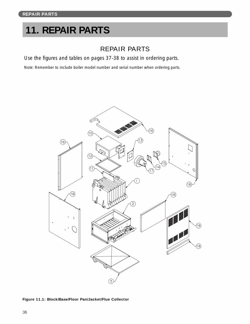
Figure 11.1: Block/Base/Floor Pan/Jacket/Flue Collector
REPAIR PARTSUse the figures and tables on pages 37-38 to assist in ordering parts.
Note: Remember to include boiler model number and serial number when ordering parts.
11. REPAIR PARTS

37
Table 11.1: Repair Parts – Block/Base/Floor Pan Jacket/Flue Collector (see note)
REPAIR PARTS
DescriptionQuantityRequired
StockCode
1
Block Assembly – 70 – 90419
Block Assembly – 105 – 90420
Block Assembly – 140 – 90421
Block Assembly – 165 – 90422
2
Assembled Steel Base – 70 – 7800
Assembled Steel Base – 105 – 7801
Assembled Steel Base – 140 – 7802
Assembled Steel Base – 165 – 7803
3 OBS CVR Door – 70 thru 165 – 51771
4 Base Blanket Seal (specify size) – 50867
5
Combustible Floor Pan Assembly – 70 – 90700
Combustible Floor Pan Assembly – 105 – 90701
Combustible Floor Pan Assembly – 140 – 90702
Combustible Floor Pan Assembly – 165 – 90703
6 Steel Burner w/ Pilot Clip 1 51539
–
Steel Burner – 70 3 51537
Steel Burner – 105 5 51537
Steel Burner – 140 7 51537
Steel Burner – 165 9 51537
7
Gas Manifold – 70 – 50978
Gas Manifold – 105 – 50979
Gas Manifold – 140 – 50980
Gas Manifold – 165 – 50981
8
Orifice Spud, #48 Natural Gas – 70 4 50894
Orifice Spud, #48 Natural Gas – 105 6 50894
Orifice Spud, #48 Natural Gas – 140 8 50894
Orifice Spud, #49 Natural Gas – 165 10 50895
Orifice Spud, #56 LP Gas – 70 4 50899
Orifice Spud, #56 LP Gas – 105 6 50899
Orifice Spud, #56 LP Gas – 140 8 50899
Orifice Spud, #56 LP Gas – 165 10 50899
9 Flame Rollout Safety Shut Off Switch – 51587
10
Flue Collector/Fan Mount – 70 – 90195
Flue Collector/Fan Mount – 105 – 90196
Flue Collector/Fan Mount – 140 – 90197
Flue Collector/Fan Mount – 165 – 90198
11 Flue Baffle - 8" (specify qty.) 1 51584
12 Flue Collector Blanket Seal (specify length) – 50866
13 Fan Gasket – 50204
14 Fan Adapter Gasket – 50203
15 Fan Adapter – 90199
16
Jacket Assembly – 70 – 6126
Jacket Assembly – 105 – 6127
Jacket Assembly – 140 – 6128
Jacket Assembly – 165 – 6129
17 Fan Fasco-702110992 – Blower 70 thru 165 – 50212

38
REPAIR PARTS
Figure 11.2: Base/Burners/Manifold
Table 11.2: Repair Parts – Base/Burners/Manifold (see note)
DescriptionQuantityRequired
StockCode
– Honeywell VR8204A-2013 Spark Gas Valve – LP Gas – 70 thru 140 – 50584
– Honeywell VR8304M-4010 Spark Gas Valve – LP Gas – 165 – 50590
– Honeywell VR8204A-2001 Spark Gas Valve – Natural Gas – 70 thru 140 – 50583
– Honeywell VR8304M-4002 Spark Gas Valve – Natural Gas – 165 – 50589
– Honeywell Q348A-1358 Pilot – LP Gas Spark – 70 thru 165 – 51814
– Honeywell Q348A-1002 Pilot – Natural Gas Spark – 50558
– Ignition Control Spark – Honeywell S8610M-1003 – 50672
– Cleveland NS2 1104-03 Switch – 1.68" W.C. Set Point Pink – 50038
– Cleveland NS2 1104-02 Switch – 1.47" W.C. Set Point Purple – 50037
– Cleveland NS2 1104-01 Switch – 1.27" W.C. Set Point Brown – 50036
– Safety Relief Valve 30 PSI Conbraco 10-408-05 – 50501
– Temperature Pressure Gauge – 51774
– Conversion Kit (To Nat from LP) – 165 – 91148
– Conversion Kit (To Nat from LP) – 70 thru 140 – 91147
– Conversion Kit (To LP from Nat) – 70 thru 165 – 90776
– Limit Control, Beckett AquaSmart 7600B – 50335
– Immersion Well, Beckett 7600T – 50341
– Immersion Sensor, Beckett 7600P – 50339
– Limit Control, Hydrolevel HydroStat 3200 – 50334
– Immersion Well, Hydrolevel – 50723
– Ignition Cable – 50640
– Relay, 24VAC Coil, DPST – 50726

39

LIFETIME LIMITED WARRANTYResidential Cast Iron Water Boilers
First Through Tenth YearThe “Manufacturer” warrants to the original owner at the original installation site that the cast iron sections ofthe Residential Cast Iron Water Boilers (the “Product”) will be free from defects in material or workmanship forten (10) years from the date of installation. If upon examination by the Manufacturer the Product is shown tohave a defect in material or workmanship during the warranty period, the Manufacturer will repair or replace,at its option, that part of the Product which is shown to be defective.
Eleventh Year and AboveThe Manufacturer warrants that the cast iron sections of its residential cast iron water boilers will remain free of defects in material or workmanship under normal usage for the lifetime of the original owner at the originalinstallation site. Should any sections be found to be defective, the Manufacturer will repair or replace, at itsoption, the original cast iron sections upon the payment of a proportionate charge based on the time thedefective section was in service. The proportionate charge will be equal to the appropriate percentage of thetrade price of the section at the time the warranty claim is made, determined as follows:
Year 11 12 13 14 15 16 17 18 19 20 21 22 23 24 25 & Above% ofTrade 5 10 15 20 25 30 35 40 45 50 55 60 65 70 75Price
This limited warranty does not apply:(a) if the Product has been subjected to misuse or neglect, has been accidentally or intentionally damaged,
has not been installed, maintained or operated in accordance with the furnished written instructions, or hasbeen altered or modified in any way.
(b) to any expenses, including labor or material, incurred during removal or reinstallation of the Product or parts thereof.
(c) to any other cast iron parts of the boiler.(d) to burners, jackets, controls, and other auxiliary equipment furnished by the Manufacturer, but
manufactured by others. Any warranties for such items shall be limited to those warranties offered by theoriginal equipment manufacturer.
(e) to damage as a result of settlement, distortion, collapse, or cracking of any foundation area, beams or pipes surrounding the Product.
(f) to any workmanship of any installer of the Product; or to Products installed outside the continental UnitedStates or Canada.
This limited warranty is conditional upon:(a) shipment, to the Manufacturer, of that part of the Product thought to be defective. Goods can only be
returned with prior written approval from the Manufacturer. All returns must be freight prepaid.(b) determination, in the reasonable opinion of the Manufacturer, that there exists a defect in material or
workmanship(c) the residential water boiler having been installed in a single–family or two–family residential dwelling.
Repair or replacement of any part under this Limited Warranty shall not extend the duration of the warrantywith respect to such repaired or replaced part beyond the stated warranty period.
THIS LIMITED WARRANTY IS IN LIEU OF ALL OTHER WARRANTIES, EITHER EXPRESS OR IMPLIED,AND ALL SUCH OTHER WARRANTIES, INCLUDING WITHOUT LIMITATION IMPLIED WARRANTIES OF MERCHANTABILITY OR FITNESS FOR A PARTICULAR PURPOSE, ARE HEREBY DISCLAIMED AND EXCLUDED FROM THIS LIMITED WARRANTY. IN NO EVENT SHALL THE MANUFACTURER BE LIABLE IN ANY WAY FOR ANY CONSEQUENTIAL, SPECIAL, OR INCIDENTAL DAMAGES OF ANYNATURE WHATSOEVER, OR FOR ANY AMOUNTS IN EXCESS OF THE SELLING PRICE OF THEPRODUCT OR ANY PARTS THEREOF FOUND TO BE DEFECTIVE. THIS LIMITED WARRANTY GIVES THE ORIGINAL OWNER OF THE PRODUCT SPECIFIC LEGAL RIGHTS. YOU MAY ALSO HAVE OTHERRIGHTS WHICH MAY VARY BY EACH JURISDICTION.
IN CANADA: 7555 TRANMERE DRIVE
MISSISSAUGA, ONT. L5S 1L4 TEL (905) 670-5888 FAX (905) 670-5782
IN UNITED STATES: 260 NORTH ELM ST.
WESTFIELD, MA 01085 TEL (413) 564-5515 FAX (413) 568-9613
www.hydrotherm.com