Embed Size (px)
Citation preview

Aerospace Systems Design Laboratory School of Aerospace Engineering • Georgia Institute of Technology
Atlanta, Georgia
Dr. Simon Briceno
NDIA 17th Annual Systems Engineering Conference October 27-30, 2014
A Virtual Simulation Platform for the Design, Testing, and Verification of Unmanned Aerial Vehicle Designs

2
Virtual Prototyping: Experience and Motivation
Des
ign,
Inte
grat
ion,
and
Te
stin
g Ti
me
Complexity
Next-Gen Aero Platforms
• Growth in systems complexity has increased risk and development time to unacceptable levels over the past 50 years
Aerospace and Military Systems (8-12% cost growth per year)
Automobiles (4% cost growth per year)
Integrated Circuits (IC) (~0% cost growth per year)
• Rapidly changing environments require systems to be designed with higher degrees of adaptability
Requirements
Conceptual Preliminary Detailed
Allocated Baseline
Production & Support
Detailed Baseline
Production Baseline
Manufacturing Considerations
• Parametric • 1st Level Analysis • Optimization
• General Performance • General Internal Layout
Traditional Paradigm Top-Down Approach
Sequential
Build
Redesign
• GT ASDL has developed a virtual prototyping framework supporting efficient design, manufacturing, product life-cycle analysis and verification of complex systems before physical prototyping
How can we collapse this gap?
• Can we learn from other walks of life to help manage the ever-growing complexity that is inherent in next-generation systems?

3
Virtual Prototyping: New Paradigm
• The answer is yes… – Rethinking systems design by pulling
“detailed” design aspects forward in design process
– Leveraging latest systems engineering methodologies and computational capabilities
– Focusing on virtual design and testing (limiting physical prototyping)
– Enabling completely integrated design platforms and transparent requirements traceability Industry Best
Practices (Knowledge)
Emerging Techniques &
Methods (Academia,
R&D)
Software Solutions
Probabilistic Analysis
Component-Based Virtual Engineering
Requirements
Physical Prototype
Bottom-Up Approach
System Composition
Components Context Library
• Multi-fidelity • Multi-Domain • Manufacturing • Ontology • Failure Modes
Virtual Prototyping, Testing, and Verification
Virtual Test Beds
• KPP’s • Scenario • Parameterization • Parameter • Uncertainty
• ‘Ilities’ • Behavior • Confidence • Thresholds
Certification
Concurrent

4
Systems Design Challenges
Does the customer
know what they
want?
What is the underlying problem?
How is it done today?
What difference can we make if successful?
How will we know if
we are successful?
What are the requirements?
Do we understand the requirements?
How do we quantify success?
Do we have the right
resources?
What are the critical functions?
What are our alternatives?
How to we manage
concept space? Are we exploring
all possible concepts?
Which concepts offer promising
solutions?
How to we make the leap from conceptual
to physical?
Does this require M&S?
Can I leverage existing models?
Do we have a verification plan?
Have we captured critical aspects?
What tests are needed?
What are the unknowns?
Can we meet requirements?
Is it worth
building?
Have we captured enough
information?
Define Conceptualize Prototype Test & Certify
Customer Centric
Understand
5
Needs
Opportunity
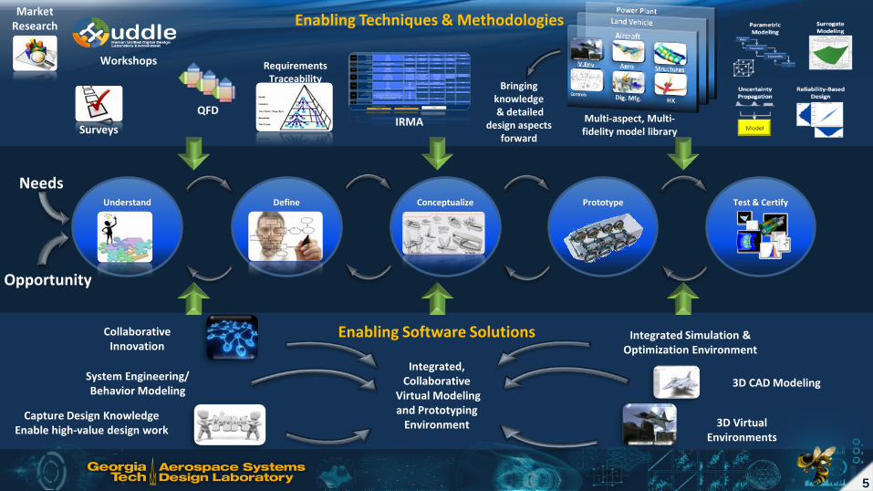
Define Conceptualize Prototype Test & Certify Understand
Enabling Techniques & Methodologies
QFD IRMA
Surveys
Workshops
Market Research
Multi-aspect, Multi-fidelity model library
Requirements Traceability
Bringing knowledge & detailed
design aspects forward
Enabling Software Solutions
System Engineering/ Behavior Modeling
Capture Design Knowledge Enable high-value design work
Integrated Simulation & Optimization Environment
3D Virtual Environments
Collaborative Innovation
Integrated, Collaborative
Virtual Modeling and Prototyping
Environment
3D CAD Modeling

6
3D CAD
• Capture Design Knowledge • Enable high-value design work
Integrated Simulation & Optimization Environment
3D Virtual Environments
Collaborative Innovation
Needs
Opportunity
CATIA DBM
Define Conceptualize Prototype Test & Certify Understand
Enabling Techniques & Methodologies
QFD IRMA
Surveys
Workshops
Market Research
Multi-aspect, Multi-fidelity model library
Requirements Traceability
Bringing knowledge & detailed
design aspects forward
Enabling Software Solutions

7
Enabling Completely Integrated Design Platforms and Transparent Requirements Traceability
Platform requirements:
• Model Based Enterprise foundation to capture descriptive & computational models across program lifecycle
• Ensure that the data is available in the right place, at the right time, and in the right format
Summarize, index, store and retrieve previous exploration information systematizing process & product data for reuse
Manage and visualize the virtual validation & verification workflow to
• Capture fully models, scenarios & results
• Understand the steps that led to a decision
• Provide full traceability and impact analysis to analyze and understand impacts of decisions and potentials for improvement
The Winning Program
8
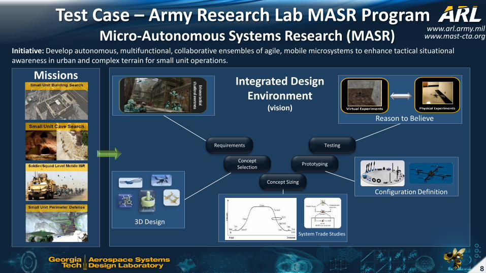
Concept Selection
Concept Sizing
Prototyping
Testing Requirements
Integrated Design Environment
(vision)
Test Case – Army Research Lab MASR Program
Missions
Initiative: Develop autonomous, multifunctional, collaborative ensembles of agile, mobile microsystems to enhance tactical situational awareness in urban and complex terrain for small unit operations.
System Trade Studies
Configuration Definition
3D Design
Reason to Believe
www.arl.army.mil Micro-Autonomous Systems Research (MASR) www.mast-cta.org

9
Translating Requirements: Operational Functions, Test Missions, and Measures of Effectiveness
Top-Level Goals
Mission Types
Test Mission
Mission MoEs Requirements
Operational Functions
GT ASDL Atrium
Program Planning & Control
Requirements
Concept Selection
Concept Sizing
Prototyping
Testing
1.2 Sense 1.1 Deploy & Startup
1.3 Create/Update
Geom. Rep.
1.4 Transfer Geom. Data
1.5 Navigate to next point
1.6 Move to next point
1.7 Evaluate for stopping
point
1.8 Shutdown

10
Define Concept Space
Given a set of requirements and potential technologies, which concepts can be explored?
Requirements
Top-Level Goals Mission Types
Test Mission
Mission MoEs
Operational Functions
Candidate Technologies/Concepts Component Library
• Library consists of multi-fidelity, multi-domain, cyber-physical models • Extensible & reusable – allows organizations to leverage internal knowledge
Morphological Analysis (IRMA)
Requirements
Concept Selection
Concept Sizing
Prototyping
Testing

11
Interactive Reconfigurable Matrix of Alternatives (IRMA)
• Purpose – A structured methodology to integrate
objective and implicit information into the concept selection process
• Objectives
– Functional Decomposition – Allows exploration and traceable reduction of
the design space from an astronomical number of combinations to a manageable set
• Characteristics – Bottom-up approach – Flexible, reconfigurable, and collaborative – Multi-level mappings – Mission scenario evaluation to score and rank
alternatives – Compatibility relations – Calculation of number of alternatives – Multi-Attribute Decision Making – Metadata Filters
Requirements
Concept Selection
Concept Sizing
Prototyping
Testing

12
Filtered IRMA for Concept Sizing
• A set of filters applied to the MASR IRMA provides a starting point for concept sizing and virtual prototyping
• TRL of 9 (mature technologies)
• Must be composed of components off-the-shelf (COTS)
Option 1 Option 2 Option 3 Option 4 Option 5 Option 6
Locomotion Wall Crawler Quadrotor yes Slither/Serpent Hopper Flapping Wing Lighter than
Air Communication Wifi yes Bluetooth Optical Wired Acoustic
Power Battery yes Capacitor Fuel Cells
Sensor - Mapping Microphone LIDAR yes Chemical Sensor SONAR RADAR Stereo video
Processing - Nav. Panda Board yes PIC Custom board Offboard PC
Processing - Movement
Ardupilot Open Pilot yes
Sensor - Location GPS Gyros Magnetometer IMU yes
Apply filters
Requirements
Concept Selection
Concept Sizing
Prototyping
Testing

13
IRMA Concept Selection
Tech 1
Tech 2
Tech 3
Tech n
Crawler, Quadrotor, Ornithopter…
Capacitor, Li-Po, Fuel Cells…
Microphone, LIDAR, SONAR…
Technology Attributes
Mass, power required, processing, memory, scaling, cost… Maneuverability, endurance/range, speed… Noise, stability, safety, terrain index… Strength, deformability, morphability, self-healing… Energy density, specific mass…
Operational functions vs. Technology Attributes
Operational Functions Perform system warmup Deploy/Startup Sense Receive/Retrieve Create/Update Geo. Data Navigate Generate planned path
2 8 9 8 5 6 7
WOF X
Generate score for each
technology
Evaluate All Possible
Alternatives
Ranked List of Concepts
Technology Attributes vs. Sub-system Technologies
Subject-matter Expert Inputs
Requirements
Concept Selection
Concept Sizing
Prototyping
Testing

14
Concept Sizing
• Concept optimized to meet requirements/constraints
– Ability to sustain flight at 50% throttle
– Doorway entry width constraint – Off-the-shelf components – Etc.
Parameter Optimal Chord 0.03 m Pitch 4.1 degree
Angular velocity 15,000 RPM Thrust 4.1 N
Power required 75 W Radius 0.104 m
Component Identification
Parameter Identification
Sizing & Optimization
Requirements
Concept Selection
Concept Sizing
Prototyping
Testing
Calculate Thrust and
Power Required
Component Weight
Estimates
Blade Geometry
Motor RPM
& Battery Specs
Inputs
Total Weight
Motor/ Propeller
Sizing
Thrust Required
Sizing
Sizing Iteration
Loop

15
System Prototyping Parameter Optimal
Chord 0.03 m Pitch 4.1 degree
Angular velocity 15,000 RPM Thrust 4.1 N Power required 75 W Radius 0.104 m
Behavior Models. CAD. Etc.
Requirements
Concept Selection
Concept Sizing
Prototyping
Testing

16
Mission Simulation
• Multi-domain physical modeling (Modelica)
• Sends distance and position data to Simultaneous Localization and Mapping (SLAM) software
• Update positions and behaviors • Detect obstacles and evaluate
distance • Return sensor information
New positions and behaviors
sent by FMI
SONAR and LIDAR data
returned by FMI
Requirements
Concept Selection
Concept Sizing
Prototyping
Testing

17
Simulation Results Test Mission:
Weber 2nd Floor Atrium, ASDL
Start
Finish
Physical Experiment
Coverage Area Full coverage
Coverage Time 4-5min
Obstacles Identified Objects = 5
Entrance Points Identified 5
Attribute R Target Value Unit
R1 Surface of floor explored > 90 %
R2 Discover obstacles --- --- ---
R3 Mission time < 10 min
R4 Reserve time = 2 min
R5 Noise at furthest point in room
< 50 dB
R6 Noise around vehicle < 70 dB
R7 Number of operators = 2 ---
R8 Deployment time < 5 min
C1 Size of the vehicle < doorway ft
Location Peak(dB) Peak(dB)
Noise at furthest point 73.9 71.9
Noise near vehicle 93.0 91.4
Mission Requirements Review
Noise level measurement
Maximum noise level is encountered at Take-Off
Measures of Effectiveness
Virtual Experiment
• Goal was to provide a comparable mapping result with physical experiments
• Captured most of the requirements • Noise was not tested in virtual environment • Test-bench improvements:
• Navigation effectiveness • Mapping effectiveness
Requirements
Concept Selection
Concept Sizing
Prototyping
Testing

18
Results and Decision Support Advances in numerical simulation techniques and computational methods have allowed for significant amounts of data to be generated, collected, and analyzed
Runtime Gateway (Isight Decision Support Tool) • Directly integrated in V6 platform for analyzing data to support decision-making • Supports intelligent exploration of data and promotes innovation through discovery of new design possibilities and early design trade-offs
Design Space Visualization Data Mining Real-time plots
Statistical processing Design parameter correlation
Robustness / Reliability
Surrogate Model Visualization
Integrated Analysis Framework
Requirements
Concept Selection
Concept Sizing
Prototyping
Testing
19
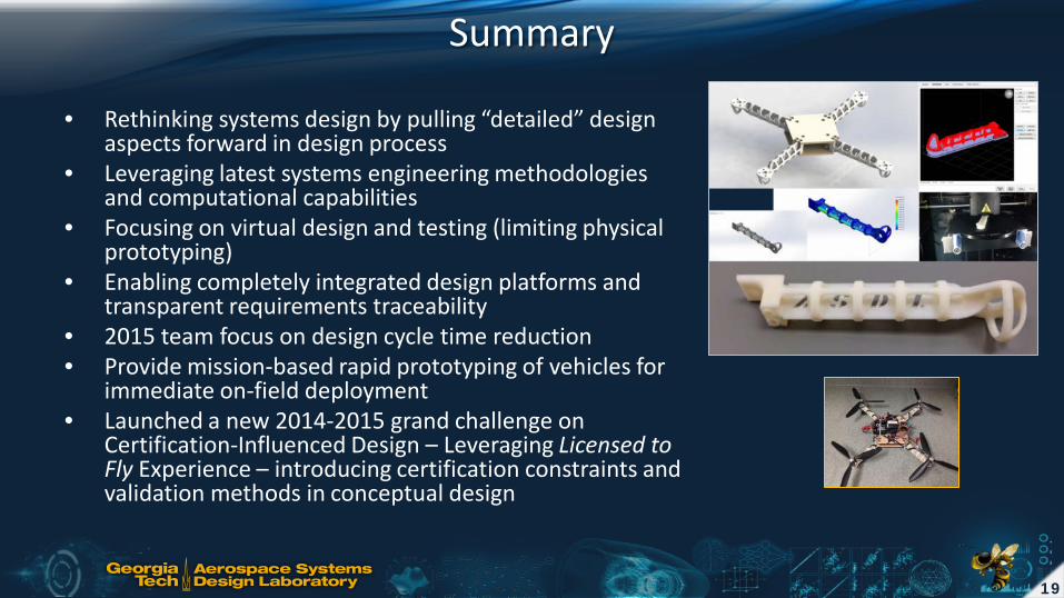
Summary
• Rethinking systems design by pulling “detailed” design aspects forward in design process
• Leveraging latest systems engineering methodologies and computational capabilities
• Focusing on virtual design and testing (limiting physical prototyping)
• Enabling completely integrated design platforms and transparent requirements traceability
• 2015 team focus on design cycle time reduction • Provide mission-based rapid prototyping of vehicles for
immediate on-field deployment • Launched a new 2014-2015 grand challenge on
Certification-Influenced Design – Leveraging Licensed to Fly Experience – introducing certification constraints and validation methods in conceptual design

20
Thank you GT Team Acknowledgements:
Etienne Demers Bouchard
Simon Briceno
Daniel Cooksey
Antoine Engerand
Evan Harrison
Christopher Jenista
Hernando Jimenez
Blaine Laughlin
Peter Mangum
Zohaib Mian
Jongki Moon
Olivia Pinon
Contact Info: Simon Briceno [email protected] Tel: 404-894-8055 http://www.asdl.gatech.edu Image references: http://www.arl.army.mil/www/default.cfm?page=332 https://alliance.seas.upenn.edu/~mastwiki/wiki/index.php?n=Repository.SeminarsAndPresentations


![Virtual Health Platform [05 Cr2 Cabrer Platform]](https://img.pdfslide.us/doc/110x75/55493080b4c9054c498c3535/virtual-health-platform-05-cr2-cabrer-platform.jpg)