Embed Size (px)
Citation preview
522
A HOMEMADE FALLOUT METER, THE KFMzr;
HOW TO MAKE AND USE ITgv! 5
FOLLOWING THESE INSTRUCTIONS MAY SAVE YOUR LIFE -
I. The Need for Accurate and Dependable Fallout Meters II. Survival Work Priorities During a Crisis
If a nuclear war ever strikes the United States, survivors of the blast and fire effects Before building a KFM, persons expecting a nuclear attack within a few hours or
would need to have reliable means of knowing when the radiation in the days and already in the place where they intend to await attack should work with
environment around their shelters had dropped enough to let them venture safelyoutside. Civil defense teams could use broadcasts of surviving radio stations to
the following priorities: (1) build or improve a high-protection-factor shelter (if
give listeners a general idea of the fallout radiation in some broadcast areas.possible, a shelter covered with 2 or 3 feet of earth and separate from flammable
However, the fallout radiation would vary widely from point to point and thebuildings); (2) make and install a KAP (a homemade shelter-ventilating pump) --
measurements would be made too far from most shelters to make them accurateif instructions and materials are available; (3) store at least 15 gallons of water for
enough to use safely. Therefore, each shelter should have some dependableeach shelter occupant -- if containers are available; (4) assemble all materials forone or two KFM’s; and (5) make and store the drying agent (by heating wallboard
method of measuring the changing radiation dangers in its own area. gypsum, as later described) for both the KFM and its dry-bucket.
During a possible nuclear crisis that was rapidly worsening, or after a nuclearattack, most unprepared Americans could not buy or otherwise obtain a falloutmeter -- an instrument that would greatly improve their chances of surviving anuclear war. The fact that the dangers from fallout radiation -- best expressed interms of the radiation dose rate, roentgens per hour (R/hr) -- quite rapidly decreaseduring the first few days, and then decrease more and more slowly, makes it veryimportant to have a fallout meter capable of accurately measuring the unseen,unfelt and changing fallout dangers. Occupants of a fallout shelter should be ableto control the radiation doses they receive. In order to effectively control theradiation doses, a dependable measuring instrument is needed to determine thedoses they receive while they are in the shelter and while they are outside foremergency tasks, such as going out to get badly needed water. Also, such aninstrument would permit them to determine when it is safe to leave the shelter forgood.
III. How to Use These Instructions to Best Advantage
1. Read ALOUD all of these instructions through Section VII, “Tools Needed,”before doing anything else.
2. Next assemble all of the needed materials and tools.
3. Then read ALOUD ALL of each section following Section VII before beginningto make the part described in that section. 2
=I
Untrained families, guided only by these written instructions and using only lowcost materials and tools found in most homes, have been able to make a KFM byworking 3 or 4 hours. By studying the operating sections of these instructions forabout 1 1/2 hours, average untrained families have been able to successfully use thisfallout meter to measure dose rates and to calculate radiation doses received,permissible times of exposure, etc.
A FAMILY THAT FAILS TO READ ALOUD ALL OF EACH z
SECTION DESCRIBING HOW TO MAKE A PART, BEFOREBEGINNING TO MAKE THAT PART, WILL MAKE AVOID-
?
ABLE MISTAKES AND WILL WASTE TIME.wh)
The KFM (Kearny Fallout Meter) was developed at Oak Ridge National Laboratory.It is understandable, easily repairable, and as accurate as most civil defense falloutmeters. In the United States in 1976 a commercially available ion chamber falloutmeter that has as high a range as a KFM for gamma radiat ion dose-ratemeasurements retailed for $600.
4. Have different workers, or pairs of workers, make the parts they are bestqualified to make. For example, a less skilled worker should start making thedrying agent (as described in Section VIII) before other workers start makingother parts. The most skilled worker should make and install thealuminum-foil leaves (Sections X and XI).
5. Give workers the sections of the instructions covering the parts they are tobuild--so they can follow the step-by-step instructions, checking off with apencil each step as it is completed.
Before a nuclear attack occurs is the best time to build, test and learn how to use aKFM. However, this instrument is so simple that it could be made even afterfallout arrives provided that all the materials and tools needed (see lists given inSections V, VI, and VII) and a copy of these instructions have been carried into theshelter.
6. Discuss the problems that arise. The head of the family often can give betteranswers if he first discusses the different possible interpretations of someinstructions with other family members, including teenagers.
7. After completing one KFM and learning to use it, if time permits make asecond KFM--that should be a better instrument.
A KFM is a simple electroscope fallout meter withwhich fallout radiation can be measured accurately.To use a KFM, an electrostatic charge must first beplaced on its two separate aluminum-foil leaves.These leaves are insulated by being suspendedseparately on clean, dry insulating threads.
To take accurate readings, the air inside a KFM mustbe kept very dry by means of drying agents such asdehydrated gypsum (easily made by heating gypsumwallboard, “sheetrock”) or silica gel. (Do not usecalcium chloride or other salt.) Pieces of drying agentare placed on the bottom of the ionization chamber(the housing can) of a KFM.
An electrostatic charge is transferred from a homemade electrostatic chargingdevice to the two aluminum-foil leaves of a KFM by means of its charging-wire.The charging-wire extends out through the transparent plastic cover of the KFM.
When the two KFM leaves are charged electrostati-cally, their like charges (both positive or bothnegative) cause them to be forced apart. When falloutgamma radiation (that is similar to X rays but moreenergetic) strikes the air inside the ionization chamberof a KFM, it produces charged ions in this enclosedair. These charged ions cause part or all of theelectrostatic charge on the aluminum-foil leaves to bedischarged. As a result of losing charge, the twoKFM leaves move closer together.
,
To read the separation of the lower edges of the twoKFM leaves with one eye, look straight down on theleaves and the scale on the clear plastic cover. Keepthe reading eye 12 inches above the SEAT. The KFM ----i-- _=should be resting on a horizontal surface. To be sure the reading eye is always at
this exact distance, place the lower end of a 12-inch ruler on the SEAT, while theupper end of the ruler touches the eyebrow above the reading eye. It is best tohold the KFM can with one hand and the ruler with the other. Using a flashlight
makes the reading more accurate.
If a KFM is made with the specified dimensions and of the specified materials, itsaccuracy is automatically and permanently established. Unlike most radiationmeasuring instruments, a KFM never needs to be calibrated or tested with aradiation source, if made and maintained as specified and used with the followingtable that is based on numerous calibrations made at Oak Ridge National Labor-atory.
The millimeter scale is cut out and attached (see photo illustrations on the followingpage) to the clear plastic cover of the KFM so that its zero mark is directly above thetwo leaves in their discharged position when the KFM is resting on a horizontalsurface. A reading of the separation of the leaves is taken by noting the number ofmillimeters that the lower edge of one leaf appears to be on, on one side of the zeromark on the scale, and almost at the same time noting the number of millimetersthe lower edge of the other leaf appears to be on, on the other side of the zero mark.The sum of these two apparent positions of the lower edges of the two leaves iscalled a KFM reading. The drawing appearing after the photo illustrations showsthe lower edges of the leaves of a KFM appearing to be 9 mm on the right and zeroand 10 on the left, giving a KFM reading of 19 mm. (Usually the lower edges of the 2
leaves are not at the same distance from the zero mark.) 2
ZAs will be fully explained later, the radiation dose rate is determined 2by:
ps 1-G) TABLE USED TO FIND DOSE RATES (R/HR) Z!cn
1. charging and reading the KFM beforeF R O M KFY READINGS
wfWE”~WEE ,eTw.m THE 11mmw3 ,WO”.? EXms”“.5 ;dexposure; *MD WC *.$*0,yG *FTEI CX?os”“.C ,~~“*IwoI*o-
FOIL LEA “CS, or;:D,F F : I N T IM E I N T E R V A L O F A N EXPOSURE
R E A D - ,S S E C ,MI N 4 M I N 1 6 M I N 1 H R.z
2. exposing it to radiation for a specifiedtime in the location where measure-
INGS R / H R R / H R R / H R R / H R R / H R
2 m m 6 .2 1 .6 0 .4 0 .1 0 .0 3ment of the dose rate is needed -- when 4 m m 1 2 . 3 .1 0 .8 0 .2 0 .0 6outdoors, holding the KFM about 3 ft. 6 m m 1 9. 4 .6 1 .2 0 .3 0 .0 8
above the ground; 8 m m 2 5 . 6 .2 1 .6 0 .4 0 .1 0 10 m m 3 1 . 7 .7 2 .0 0 .5 0 .1 31 2 m m 3 7. 9 .2 2 .3 0 .6 0 .1 5
3. reading the KFM after its exposure; 1 4 m m 4 3. 1 1 . 2.7 0 .7 0 .1 8
4. calculating, by subtraction, the difference between the reading taken beforeexposure and the reading taken after exposure;
5. using this table to find what the dose rate was during the exposure -- as will bedescribed later.
Instructions on how to use a KFM are given after those detailing how to make andcharge this fallout meter.
To get a clearer idea of the construction and use of a KFM, look carefully at thefollowing photos and read their captions.
A.
B.
An Uncharged KFM. The charging wire has been pulled to one side by itsadjustment-thread. Thisphoto was taken lookings t r a i g h t d o w n a t t h eupper edges of the twoflat , 8-ply aluminumleaves. At this angle theleaves are barely visible,hanging vertically side byside directly under thezero mark, touching eachother and with their endseven. Their suspension-threads insulate the
leaves. These threadsare almost parallel andtouch (but do not cross)each other where theyextend over the top of therim of the can.
Charging a KFM by a Spark-Gap Discharge from a Tape That Has BeenElectrostatically Charged by Being Unwound Quickly. Note that the chargedtape is moved so that itssurface is perpendicularto the charging-wire.
The high-voltage electro-static charge on the un-wound tape (that is aninsulator) jumps thespark-gap between thetape and the upper end ofthe charging-wire, andthen flows down thecharging-wire to chargethe insulated aluminum-foil leaves of the KFM.(Since the upper edges ofthe two leaves are 3/4 inchbelow the scale and thisis a photo taken at anangle, both leaves appearto be under the right sideof the scale.)
C.
D.
A Charged KFM. Notethe separat ion of theupper edges of its t w oleaves. T h e charging-wire has been raised toan almost horizontal pos-ition so that its lower endis too far above the alu-minum leaves to permitelectrical leakage fromthe leaves back up thecharging-wire and intothe outside air.
Also note the SEAT, apiece of pencil taped tothe right side of the can,opposite the chargingwire.
Reading a KFM. A 12-inch ruler rests on theSEAT and is held vert-ical, while the reader’seyebrow touches theupper end of the ruler.The lower edge of theright leaf is under 8 onthe scale and the loweredge of the left leaf isunder 6 on the scale,giving a KFM reading of14.
For accurate radiationmeasurements , a KFMshould be placed on anapproximately horizontalsurface, but the chargeson i ts two leaves andtheir displacements donot have to be equal.
INS
TR
UC
TIO
NS
, P
age
5
f214.h
. A
DJ
US
TM
EN
T
TH
RE
AD
(NY
LO
N
IS B
ES
T)
‘/.-I”.
T
AP
E
,“E
RT
ICA
L,
RE
MO
VA
BL
E
TR
AN
SP
AR
EN
TC
OV
ER
AN
D
CH
AR
GIN
G
WIR
E
AN
D
mEC
UR
Eb
ET
AIL
)
TO
F
IT
OV
ER
S
EA
T
ON
C
AN
‘/,-In.
TA
PE
AR
OV
NO
E
DG
E
OF
S
KIR
T
OF
C
OV
ER
THREAD
TIE
D
TO
TO
P
VIE
WT
OG
GL
E
(SM
AL
L
SL
IVE
R(C
OV
ER
A
ND
C
HA
RG
ING
W
IRE
N
OT
S
HO
WN
)
OF
W
OO
D
=b
in. L
ON
G1
TA
PE
T
OG
GL
E
TO
OU
TS
IDE
O
F
CA
Nt-k
in.1
f%
2
48
)
bO
TT
OM
OF
C
AN
INS
IDE
D
AY
2 G/qG
in
.
(Th
is is M a F
ull S
cale Dm
win
g).
V. Materials Needed 10. An ordinary wooden pencil and a small toothpick (or split a small sliver ofwood).
A . F o r the KFM: (In the following list, when more than one alternative materialis given, the best material is listed first.)
1. Any type metal can, approximately 2-9/16 inches in diameter inside and2-7/8 inches high inside, washed clean with soap. (This is the size of astandard 8-ounce can. Since most soup cans, pop cans, and beer cans alsoare about 2-9/16 inches in diameter inside, the required size of can canalso be made by cutting down the height of more widely available cans --as described in Section IX of these instructions.)
2.
3.
4.
5.
6.
7.
8.
9.
Standard aluminum foil -- 2 square feet. (In 1977, 2 square feet of a typicalAmerican aluminum foil weighed about 8.2 grams -- about 0.29 OZ.) (Ifonly “Heavy Duty” or “Extra Heavy Duty” aluminum foil is available,make 5-ply leaves rather than 8-ply leaves of standard foil; the resultantfallout meter will be almost as accurate.)
Doorbell-wire, or other light insulated wire (preferably but not necessarilya single-strand wire inside the insulation) -- 6 inches.
Any type of lightweight thread (preferably but not necessarily nylon).(Best is twisted nylon thread; next best, unwaxed lightweight nylon dentalfloss; next best, silk; next best, polyester.) -- 3 feet. (Thread should beCLEAN, preferably not having been touched with fingers. Monofilamentnylon is too difficult to see, handle, and mark.)
A piece of clear plastic -- a 6 x 6 inch square. Strong polyethylene (4 milsthick) used for storm-proofing windows is best, but any reasonably stoutand rather clear plastic will serve. The strong clear plastic used to wrap
pieces of cheese, if washed with hot water and soap, is good. Do not use
weak plastic or cellophane.
Cloth duct tape (“silver tape”), or masking tape, or freezer tape, orScotch-type tape -- about 10 square inches. (Save at least 10 feet of ScotchMagic Transparent Tape for the charging device.)
Band-Aid tape, or masking tape, or freezer tape, or Scotch transparenttape, or other thin and very flexible tapes -- about 2 square inches.
Gypsum wallboard (sheetrock) -- about l/2 square foot, best about 1 /2inch thick. (To make the essential drying agent.)
Glue -- not essential, but useful to replace Band-Aid and other thin tapes.“One hour” epoxy is best. Model airplane cement is satisfactory.
11. Two strong rubber bands, or string.
B. For the Charging Devices:
1. Most hard plastic rubbed on dry paper. This is the best method.
a. Plexiglas and most other hard plastics, such as are used in drafts-men’s triangles, common smooth plastic rulers, etc. -- at least 6 incheslong.
b. Dry paper -- Smooth writing or typing paper. Tissue paper, news-paper, or facial tissue such as Kleenex, or toilet paper are satisfactoryfor charging, but not as durable.
2. Scotch Magic Transparent Tape (3/4 inch width is best), or Scotch 2. Transparent Tape, or P.V.C. (Polyvinyl chloride) insulating electrical 2
tapes, or a few of the other common brands of Scotch-type tapes. (Some 2plastic tapes do not develop sufficiently high-voltage electrostatic chargeswhen unrolled quickly.) This method cannot be used for charging a KFM
2
inside a dry-bucket, needed for charging when the air is very humid.5
5
C. For Determining Dose Rates and Recording Doses Received: 2%
1. A watch -- preferably with a second hand. Q1
2. A flashlight or other light, for reading the KFM in a dark shelter or atnight.
3. Pencil and paper -- preferably a notebook.
D. For the Dry-Bucket: (A KFM must be charged inside a dry-bucket if the air isve ry humid , a s i t o f t en i s i n s ide a c rowded ,long-occupied shelter lacking adequate forced vent-ilation.)
1. A large bucket, pot, or can, preferably with a top diameter of at least 11inches.
2. Clear plastic (best is 4-mil-thick clear plastic used for storm windows). Asquare piece 5 inches wider on a side than the diameter of the bucket to beused.
3. Cloth duct tape, one inch wide and 8 feet long (or 4 ft., if 2 inches wide).Or 16 ft. of freezer tape one inch wide.
4.
5.
6.
7.
8.
Two plastic bags 14 to 16 inches in circumference, such as ordinary plasticbread bags. The original length of these bags should be at least 5 inchesgreater than the height of the bucket.
About one square foot of wall board (sheetrock), to make anhydrite dryingagent.
Two l-quart Mason jars or other airtight containers, one in which to storeanhydrite and another in which to keep dry the KFM charging devices.
Strong rubber bands -- enough to make a loop around the bucket. Orstring.
Four square feet of aluminum foil, to make a vapor-proof cover -- useful,but not essential.
VI. Useful but not Essential Materials--Which Could be Obtained Before a Crisis--
1. An airtight container (such as a large peanut butter jar) with a mouth at least 4inches wide, in which to keep a KFM, along with some drying agent, when it isnot being used. Keeping a KFM very dry greatly extends the time duringwhich the drying agent inside the KFM remains effective.
2. Commercial anhydrite with a color indicator, such as the drying agent Drierite.This granular form of anhydrite remains light blue as long as it is effective as adrying agent. Obtainable from laboratory supply sources.
VII. Tools Needed
Small nail - sharpenedStick, or a wooden tool handle
(best 2 - 2 1/2 inch diameter and at least 12 inches long)HammerPliersScissorsNeedle - quite a large sewing needle, but less than 2 1/2 inches longKnife with a small blade -- sharpRuler (12 inches)
VIII. Make the Drying Agent
-- The Easiest Part to Make, but Time Consuming --
For a KFM to measure radiation accurately, the air inside its ionizationchamber must be kept very dry. An excellent drying agent (anhydrite) can bemade by heating the gypsum in ordinary gypsum wallboard (sheetrock). DoNOT use calcium chloride.
Take a piece of gypsum wallboard approximately 12 inches by 6 inches, andpreferably with its gypsum about 3/8 inches thick. Cut off the paper and glue,easiest done by first wetting the paper. [Since water vapor from normal airpenetrates the plastic cover of a KFM and can dampen the anhydrite and makeit ineffective in as short a time as two days, fresh batches of anhydrite must bemade before the attack and kept ready inside the shelter for replacement. Theuseful life of the drying agent inside a KFM can be greatly lengthened bykeeping the KFM inside an airtight container (such as a peanut butter jar witha 4-inch-diameter mouth) with some drying agent, when the KFM is not beingused.] 5Z
Y
Break the white gypsum filling into small pieces and make the Zlargest no more than l/2 in. across. (The tops of pieces larger “‘:-..‘. I+, 2than this may be too close to the aluminum foil leaves.) If the jf/R.lny:
gypsum is dry, using a pair of pliers makes breaking it easier.D”
s: 2 .:. 5 :,7.:5.;. L’ E
Make the largest side of the largest pieces no bigger than this.v,
?
Dry gypsum is not a drying agent. To drive the water out of the gypsum %
molecules and produce the drying agent (anhydrite), heat the gypsum in an qoven at its highest temperature (which should be above 400 degrees F) for onehour. Heat the gypsum after placing the small pieces no more than two piecesdeep in a pan. Or heat the pieces over a fire for 20 minutes or more in a pan orcan heated to a dull red.
If sufficient aluminum foil and time are available, it is best to heat the gypsumand store the anhydrite as follows:
a.
b.
So that the right amount of anhydrite can be taken quickly out of itsstorage jar, put enough pieces of gypsum in a can with the same diameteras the KFM, measuring out a batch of gypsum that almost covers thebottom of the can with a single layer.
Cut a piece of aluminum foil about 8 in. x 8 in. square, and fold up itsedges to form a bowl-like container in which to heat one batch of gypsumpieces.
C. Measure out 10 or 12 such batches, and put each batch in its aluminum foil“bowl.”
d. Heat all of these filled “bowls” of gypsum in hottest oven for one hour.
6.
7.
8.
e. As soon as the aluminum foil is cool enough to touch, fold and crumplethe edges of each aluminum foil “bowl” together, to make a roughaluminum-covered “ball” of each batch of anhydrite.
f. Promptly seal the batches in airtight jars or other airtight containers, andkeep containers closed except when taking out an aluminum-covered“ball.”
Since anhydrite absorbs water from the air very rapidly, quickly put it in a dryairtight container while it is still quite hot. A Mason jar is excellent.
To place anhydrite in a KFM, drop in the pieces one by one, being careful notto hit the leaves or the stop-threads. The pieces should almost cover thebottom of the can, with no piece on top of other pieces.To remove anhydrite from a KFM, use a pair of scissors or tweezers as
forceps, holding them in a vertical position and not touching the leaves.
IX. Make the Ionization Chamber of the KFM(To Avoid Mistakes and Save Time,
Read All of This Section ALOUD Before Beginning Work.)
Remove the paper label (if any) from an ordinary 8-ounce can from which thetop has been smoothly cut. Wash the can with soap and water and dry it. (An8-ounce can has an inside diameter of about 2-9/16 inches and an inside heightof about 2-7/8 inches.)
Skip to step 3 if an 8-ounce can is available. If an 8-ounce can is not available,reduce the height of any other can having an inside diameter of about 2-9/16inches (such as most soup cans, most pop cans, or most beer cans). To cut offthe top part of a can, first measure and mark the line on which to cut. Then tokeep from bending the can while cutting, wrap newspaper tightly around astick or a round wooden tool handle, so that the wood is covered with 20 to 30thicknesses of paper and the diameter (ideally) is only slightly less than thediameter of the can.
One person should hold the can over the paper-covered stick while a secondperson cuts the can little by little along the marked cutting line. If leathergloves are available, wear them. To cut the can off smoothly, use a file, or usea hacksaw drawn backwards along the cutting line. Or cut the can with asharp, short blade of a pocketknife by: (1) repeatedly stabbing downwardvertically through the can into the paper, and (2) repeatedly making a cut aboutl/4 inch long by moving the knife into a sloping position, while keeping itspoint still pressed into the paper covering the stick.
Next, smooth the cut edge, and cover it with small pieces of freezer tape orother flexible tape.
3.
4.
5.
6.
Cut out the PAPER PATTERN TO WRAP AROUND KFM CAN. (Cutone pattern out of the following Pattern Page A.) Glue (or tape) thispattern to the can, starting with one of the two short sides of the pattern.Secure this starting short side directly over the side seam of the can.Wrap the pattern snugly around the can, gluing or taping it securely as itis being wrapped. (If the pattern is too wide to fit flat between the rimsof the can, trim a little off its lower edge.)
Sharpen a small nail, by filing or rubbing on concrete, for use as a punchto make the four holes needed to install the stop-threads in the ionizationchamber (the can). (The stop-threads are insulators that stop thecharged aluminum leaves from touching the can and being discharged.)
Have one person hold thecan over a horizontal stick ora round wooden tool-handle,that ideally has a diameterabout as large as the dia-meter of the can. Then asecond person can use thesharpened nail and a ham-mer to punch four very smallholes through the sides ofthe can at the points shownby the four crosses on thepattern. Make these holesjust large enough to run aneedle through them, andthen move the needle in theholes so as to bend back theobstructing points of metal.
PUNCH SMALL
SHARPENEDSMALL NAIL
HANDLE INSIDE
__---J
The s top-threads can beinstalled by using a needleto thread a single threadthrough all four holes. Usea very clean thread, prefer-ably nylon, and do not touchthe parts of this thread that
TO NEEDLE
SMALL
TOGGLE
TIED TO
END OF
THREAD
TOGGLE
THIS SMALL
TlEDm
1/2 in. FROM
CAN; LATER
THREAD IS
will be inside the can andwill serve as the insulating STOP-stop-threads. Soiled threads THREADare poor insulators.(See illustrations.)
SIDE OF CAN
SINGLE THREAD THREADED THROUGH 4 HOLES
TO MAKE 2 STOP-THREADS
CUT EXACTL Y ON SIDE LINES \
$ H O L E
G F O R
STOP-
THREAD
TABLE USED TO FIND DOSE RATES (R/HR)FROM KFM READINGS
‘DIFFERENCE BETWEEN THE READING BEFORE EXPOSURE
AND THE READlNG AFTER EXPOSURE (8-PL Y STANDARD.
FOIL LEAVES,
DIFF.* IN TIME INTERVAL OF AN EXPOSURE
READ- 15SEC.11 MIN.14MIN.hGMIN.I 1 HR.
I N G S R/HR R/HR R/HR R/HR R/HR
2 mm 1 6.2 1 1.6 1 0.4 1 0.1 1 0.034mm 12. 3.1 ~ 0.8 0.2 0.06
6mm 19. 4.6 1.2 0.3 0.08
8mm 25. 6.2 1.6 0.4 0.10
10 mm 31. 7.7 2.0 0.5 0.1312mm 37. 9.2 2.3 0.6 0.1514 mm 43. 11. 2.7 0.7 0.18
TOP OF CAN (BELOW LIP)
FASTEN THREADS HOLDING ALUMINUM LEAVES HERE
/TOP OF l-IN. PENCIL (FOR RULER REST)
SEAT
FOR 9STOP- 2
T H R E A D a
t!
HOLES FOR STOP-THREAD
BOTTOM OF CAN (ABOVE LIP)
CUT EXACTL Y ON SIDE LINES \ “9 5_-_!_g
TOP OF CAN IBELOWLIPI
FASTEN THREADS HOLDING ALUMINUM LEAVES HERE
03gE:
:i
tIz_
TABLE USED TO FIND DOSE RATES (R/HR)
FROM KFM READINGSw
$3
‘DIFFERENCE BETWEEN THE READING BEFORE EXPOSURE
AND THE READING AFTER EXPOSURE (8 PL Y STANDARD
FOIL LEA VE
1-
/TOP OF I-IN. PENCIL (FOR RULER REST)
HOLE
FOR
STOP-
THREAD
10 mm12mm14 mm
S)
TIME INTERVAL OF AN EXPOSUREz
15 SEC. 1 MIN. 4MIN. 16MIN. 1 HR.s
R/HR R/HR R/HR R/HR R/HR
6.2 1.6 0.4 0.1 0.03 HOLES FOR STOP-THREAD :
12. 3.1 0.8 0.2 0.06 FOR 2 ci19. 4.6 1.2 0.3 0.08 STOP-
25. 6.2 1.6 0.4 0.10 THREAD :
31. 7.7 2.0 0.5 0.13 f!
37. 9.2 2.3 0.6 0.151 43. 1 11. 1 2.7 1 0.7 10.18 BOTTOM OF CAN (ABOVE LIP)
PAPER PATTERN TO WRAP AROUND KFM CAN (GLUE OR TAPE SECURELY TO CAN)
CUT OUT THESE PATTERNS, EACH OF WHICH IS THE EXACT SIZE FOR A KFM.
PATTERN PAGE (A) CAUTION: XEROX COPIES OF THESE PATTERNS WILL BE TOO LARGE.
Before threading the thread through the four holes, tie a small toggle (see thepreceding sketch) to the long end of the thread. (This toggle can easily be madeof a very small sliver of wood cut about 3/8 in. long.) After the thread has beenpulled through the four holes, attach a second toggle to the thread, about l/2 inchfrom the part of the thread that comes out of the fourth hole. Then the thread canbe pulled tightly down the side of the can and the second small toggle can betaped securely in place to the side of the can. (If the thread is taped down withouta toggle, it is likely to move under the tape.)
The first toggle and all of the four holes also should be covered with tape, toprevent air from leaking into the can after it has been covered and is being usedas an ionization chamber.
pp d--(14)
X.. ‘Make Two Separate 8-Ply Leaves of Standard[Not Heavy Duty*] Aluminum Foil
Proceed as follows to make each leaf:1.
2.
3.
4.
5.
6.
Cut out a piece of standard aluminumfoil approximately 4 inches by 8 inches.
Fold the aluminum foil to make a 2-ply(= 2 thicknesses) sheet approximately 4inches by 4 inches.
Fold this 2-ply sheet to make a 4-plysheet approximately 2 inches by 4inches.t
z
THE SQUARE ka
CORNER
8-PLYSHEET
THIRD-FOLD EDGE
Fold this 4-ply sheet to make an 8-ply sheet (8 sheets thick) approximately 2inches by 2 inches, being sure that the two halves of the second-fold edge areexactly together. This third folding makes an 8-ply aluminum foil sheet withone comer exactly square.
Cut out the FINISHED-LEAF PATTERN, found on the following Pattern PageB. Note that this pattern is NOT a square and that it is smaller than the 8-plysheet. Flatten the 8 thicknesses of aluminum foil with the fingers until theyappear to be a single thin, flat sheet.
Hold the FINISHED-LEAF PATTERN on top of the 8-ply aluminum foilsheet, with the pattern’s THIRD-FOLD EDGE on top of the third-fold edge ofthe 8-ply a luminum sheet . Be sure that one lower corner of theFINISHED-LEAF PATTERN is on top of the exactly square corner of the8-ply aluminum sheet.
7.
8.
9.
10.
11.
While holding a straight edgealong the THREAD LINE of thepattern, press with a sharp pencilso as to make a shallow groove forthe THREAD LINE on the 8-plyaluminum sheet. Also using asharp pencil, trace around the topand side of the pattern, so as toindent (groove) the 8-ply foil.
Remove the pattern, and cut outthe 8-ply aluminum foil leaf.
While holding a straight edgealong the indented THREADLINE, lift up the OPEN EDGE ofthe 8-ply sheet (keeping all 8 pliestogether) until this edge is ver-tical, as illustrated. Remove thestraight edge, and fold the 8-plyaluminum along the THREADLINE so as to make a flat-foldedhem.
Open the flat-folded hem of thefinished leaf until the 8-ply leaf isalmost flat again, as shown by thepat tern, f rom which the FIN-ISHED-LEAF PATTERN has al-ready been cut.
Prepare to attach the aluminum-foil leaf to the thread that willsuspend it inside the KFM.
THREAD
L I N E -
THE
SQUARE
CORNER
OF 8-PLY
SHEET
THIRD-FOLD EDGE
OF 8-PLY SHEET
*If only heavy duty aluminum foil (sometimes called “extra heavy duty”) isavailable, make 5-ply leaves of the same size, and use the table for the 8-ply KFMto determine radiation dose rates. To make a 5-ply leaf, start by cutting out apiece of foil approximately 4 inches by 4 inches. Fold it to make a 4-ply sheetapproximately 2 inches by 2 inches, with one corner exactly square. Next from asingle thickness of foil cut a square approximately 2 inches by 2 inches. Slip thissquare into a 4-ply sheet, thus making a 5-ply sheet. Then make the 5-ply leaf,using the FINISHED-LEAF PATTERN, etc. as described for making an 8-ply leaf.
INS
TR
UC
TIO
NS
, Page 1
1
PA
TT
ER
N F
OR
CLE
AR
-PLA
ST
IC C
OV
ER
FO
R K
FM
CA
N
TH
E P
AP
ER
SC
ALE
TO
TH
E C
OV
ER
OF
CA
N,
TH
E K
FM
LE
AV
ES
SH
OR
T S
IDE
OP
EN
E
DG
E
CU
T A
LO
NG
wL3T
HR
EA
D LIN
EE
ND
S O
F M
AR
KS-
IIII~
IllI~llII~
llII~llll~
Illl~llIl~
lIIl~llIl~
Illl
3j
AL
SO
CU
T O
N2
0
15
1
0
5
0
5
10
1
5
20
-
s!
TH
IS
LIN
E
8-P
LY
LE
AF
sC
UT
AL
ON
G
EN
DS
OF
MA
RK
S-
IIII~
lIII~IIlI~
IIII~IIIl~
IIlI/IIII~IIIl~
lIII/IIIl
TH
IRD
-FO
LD
ED
GE
AL
SO
CU
T O
N2
0
15
1
0
5
0
5
10
1
5
20
-
TH
IS
LIN
E
FIN
ISH
ED
-LE
AF
PA
TT
ER
N
(CU
T O
UT
EX
AC
TL
Y O
N S
IDE
LIN
ES
) P
AP
ER
SC
ALE
(TO
BE
CU
T O
UT
)
CA
UT
ION
: X
ER
OX
C
OP
IES
O
F T
HE
F
INIS
HE
D-L
EA
F A
ND
T
HE
PA
TT
ER
N P
AG
E (B
)S
CA
LE
PA
TT
ER
NS
WIL
L B
E S
LIG
HT
LY
TO
O L
AR
GE
.
If no epoxy glue* is available to hold down the hem and prevent thethread from slipping in the hem, cut two pieces of tape (Band-Aid tape isbest; next best is masking or freezer tape; next best, Scotch tape). Afterfirst peeling off the paper backing of Band-Aid tape, cut each piece oftape l/8 inch by 1 inch long. Attach these two pieces of tape to thefinished 8-ply aluminum leaf with the sticky sides up, except for theirends. As shown by the pattern on the following pattern page, secure l/8inch of one end of a tape strip near one corner of the 8-ply aluminum foilleaf by first turning under this l/8-inch end; that is, with this end’ssticky side down. Then turn under the other l/8-inch-long end, andattach this end below the THREAD LINE. Slant each tape strip asillustrated on Pattern (C).
Be sure you have read through step 18 before you do anything else.
12.
13.
14.
15.
16.
Cut an 8-l/2-inch piece of fine, unwaxed, very clean thread. (Nylontwisted thread, unwaxed extra-fine nylon dental floss, or silk thread arebest in this order. Nylon monofilament “invisible” thread is an excellentinsulator but is too difficult for most people to handle.)
Cut out Pattern (C), the guide sheet used when attaching a leaf to itssuspending thread. Then tape Pattern (C) to the top of a work table.Cover the two “TAPE HERE” rectangles on Pattern (C) with pieces oftape, each piece the size of the rectangle. Then cut two other pieces oftape each the same size and use them to tape the thread ONTO the guidesheet, on top of the “TAPE HERE” rectangles.
Be very careful not to touch the two l-inch parts of the thread next to theoutline of the finished leaf, since oil and dirt even on clean fingers willreduce the electrical insulating value of the thread between the leaf andthe top rim of the can.
With the thread still taped to the paper pattern and while slightly liftingthe thread with a knife tip held under the center of the thread, slip thefinished leaf under the thread and into position exactly on the top of theleaf outlined on the pattern page. Hold the leaf in this position with twofingers.
While keeping the thread straight between its two taped-down ends,lower the thread so that it sticks to the two plastic strips. Then press thethread against the plastic strips.
With the point of the knife, hold down the center of the thread againstthe center of the THREAD LINE of the leaf. Then, with two fingers,carefully fold over the hem and press it almost flat. Be sure that thethread comes out of the corners of the hem. Remove the knife, and pressthe hem down completely flat against the rest of the leaf.
Make small marks on the thread at the two points shown on the patternpage. Use a ballpoint pen if available.
17.
18.
Loosen the second two small pieces of tape from the pattern paper, but leavethese tapes stuck to the thread.
Cut 5 pieces of Band-Aid tape, each approximatelyl/8 inch by l/4 inch, this small. n
Use 3 of these pieces of tape to secure the centers of the side edges of the leaf.Place the 5 pieces as illustrated in the SIDE VIEW sketch below.
O R N L D W G 7 6 .6 5 4 2
5 PIECES OF
I1/8 IN. X 1/4 IN.
I 3
I
: AND LATER TO CAN m
SIDE VIEW END VIEW
S H O WI N G T H E T W O L E A V E S C H A R G E D
(W H E N N O T C H A R G E D , T H E L E A V E S H A N G
P E R P E N DI C U L A R A N D T O U C H I N G .)
*If using epoxy or other glue, use only a very little to hold down the hem, toattach the thread securely to the leaf and to glue together any open edges of theplied foil. Most convenient is “one hour” epoxy, applied with a toothpick. Modelairplane cement requires hours to harden when applied between sheets ofaluminum foil. To make sure no glue stiffens the free thread beyond the uppercorners of the finished leaf, put no glue within l/4 inch of a point where thread willgo out from the folded hem of the leaf.
The instructions in step 11 are for persons lacking “one hour” epoxy or the timerequired to dry other types of glue. Persons using glue instead of tape to attach theleaf to its thread should make appropriate use of the pattern on the following pageand of some of the procedures detailed in steps 12 through 18.
COVER THE TWO "TAPE HERE" RECTANGLES WITH SAME-SIZED PIECES
OF TAPE, IN ORDER TO KEEP FROM TEARING THIS PAPER WHENREMOVING TWO ADDITIONAL PIECES OF TAPE. THEN, BY PUTTINGTWO OTHER PIECES OF TAPE THIS SAME SIZE ON TOP OF THE FIRST
TWO PIECES, TAPE THE THREAD ONTO THIS GUIDE SHEET, AND LATERATTACH A LEAF TO THE TAPED-DOWN THREAD.
IL TAPE HERE TO HOLD
THREAD SECURELY
OVER THREAD LINE
USE BALLPOINT PEN TO
MARK THREAD HEREf
MARK THREAD HERE
TAPE T A P E J
/- H E R E 4 THREAD LINEI I& , c / THREAD LINE HERE
DO NOT TOUCH DO NOT TOUCH
OR MARK THISOF THREAD
THIS I-INCH PART
l-INCH PART
OF THE THREADOF FINISHED L BAND-AID PLASTIC (1/8” X 1”)
ALUMINUM-F0I L WITH STICKY SIDE UP AND
I LEAFI
ENDS FOLDED UNDER SO AS
DC;: %-(23I 1
TO STICK TO ALUMINUM
(OR USE A VERY LITTLE EPOXY.)
PATTERN (C)(Cut out this guide along its border lines and tape to the top of a work table.)
WARNING: The parts of the thread that will be inside the can and on which the leaf will
be suspended must serve to insulate the high-voltage electrical charges to be placed on the leaf.
Therefore, the suspended parts of the thread must be kept very clean.
4.
XI. Install the Aluminum-Foil Leaves 5.
Use the two small pieces of tape stuck to the ends of a leaf-suspending threadto attach the thread to the outside of the can. Attach the tapes on oppositesides of the can, so as to suspend the leaf inside the can. See END VIEWsketch. Each of the two marks on the attached thread MUST rest exactly onthe top of the rim of the can, preferably in two very small notches filed in thetop of the rim of the can. Each of these two marks on a thread should bepositioned exactly above one of the two points shown on the pattern wrappedaround the can. Be sure that the hem-side of each of the two leaves facesoutward. See END VIEW sketch.
Next, the suspending thread of the first leaf should be taped to the top of therim. Use a piece of Band-Aid only about l/8 in. x l/4 in., sticking it to the rimof the can so as barely to cover the thread on the side where the second leaf willbe suspended. Make sure no parts of the tapes are inside the can.
Position and secure the second leaf, being sure that:
a.
b.
C.
d.
e.
f.
g.
The smooth sides of the two leaves are smooth (not bent) and face eachother and are flush (= “right together”) when not charged. See ENDVIEW sketch and study the first photo illustration, “An UnchargedKFM”.
The upper edges of the two leaves are suspended side by side and at thesame distance below the top of the can.
The leaf-suspending threads are taped with Band-Aid to the top of the rimof the can (so that putting the cover on will not move the threads).
No parts of the leaf-suspending threads inside the can are taped down tothe can or otherwise restricted.
The leaf-suspending parts of the threads inside the can do not cross over,entangle or restrict each other.
The threads come together on the top of the rim of the can, and that theleaves are flat and hang together as shown in the first photo illustration,“An Uncharged KFM.”
If the leaves do not look like these photographed leaves, make new, betterleaves and install them.
Cover with tape the parts of the threads that extend down the outside of thecan, and also cover with more tape the small pieces of tape near the ends of thethreads on the outside of the can.
6.
To make the SEAT, cut a piece of a wooden pencil, or a stick, about one inch
long and tape it securely to the side of the can along the center line markedSEAT on the pattern. Be sure the upper end of this piece of pencil is at thesame position as the top of the location for the SEAT outlined on the pattern.The top of the SEAT is 3/4 inch below the top of the can. Be sure not to coveror make illegible any part of the table printed on the paper pattern.
Cut out one of the “Reminders for Operators” and glue and/or tape it to theunused side of the KFM. Then it is best to cover all the sides of the finishedKFM with clear plastic tape or varnish. This will keep sticky-tape on the end ofan adjustment thread or moisture from damaging the “Reminders” or thetable.
XII. Make the Plastic Cover
Cut out the paper pattern for the cover from the Pattern Page (B).
From a piece of clear, strong plastic, cut a circle approximately the same sizeas the paper pattern. (Storm-window polyethylene plastic, 4 mils thick, isbest.)
Stretch the center of this circular piece of clear plastic over the open end of thecan, and pull it down close to the sides of the can, making small tucks in the“skirt,” so that there are no wrinkles in the top cover. Hold the lower part ofthe “skirt” in place with a strong rubber band or piece of string. (If anothercan having the same diameter as the KFM can is available, use it to make thecover -- to avoid the possibility of disturbing the leaf-suspending threads.)
Make the cover so it fitssnugly, but can be taken
I+ &-_!23\
rCOVER
off and replaced readily. (CLEARKEEP THIS SMALL PART PLASTIC)
Just below the top of therim of the can, bind thecovering plastic in placew i t h a l/4-inch-widepiece of strong tape.(Cloth duct tape is best. Ifonly freezer or maskingtape is available, use twothicknesses.)
Keep vertical the smallpar t of the tape thatpresses against the rim ofthe can while pulling the
OF THE 1/4 IN. TAPE
VERTICAL YWHILE PULLING TAPE INSIDEAROUND RIM OF CAN OF CAN
RUBBERBAND
O R
-%:STRING
EDGE 1OF PLASTIC
I
COVER
length of the tape horizontally around the can so as to bind the top of the plasticcover snugly to the rim. If this small part of the tape is kept vertical, the loweredge of the tape will not squeeze the plastic below the rim of the can to such asmall circumference as to prevent the cover from being removed quite easily.
INSTRUCTIONS
PAGE 15
REMINDERS FOR OPERATORS
THE DRYING AGENT INSIDE A KFM
IS O.K. IF, WHEN
THE CHARGED
KFM IS NOT EXPOSED TO RADIA-
TION, ITS READINGS DECREASE
BY 1 MM OR LESS IN 3 HOURS.
READING: WITH THE READING EYE
12 INCHES VERTICALLY ABOVE THE
SEAT, NOTE ON THE MM SCALE THE
SEPARATION OF THE LOWER EDGES
OF THE LEAVES.
IF THE RIGHT
LE
AF
IS AT 10 MM AND THE LEFT
LEAF IS AT 7 MM, THE KFM READS
17 MM. NEVER TAKE A READING
WHILE A LEAF IS TOUCHING A
STOP-THREAD. NEVER USE A KFM
READING THAT IS LESS THAN 5MM.
REMINDERS FOR OPERATORS
FINDING HOW LONG IT TAKES TO
THE DRYING AGENT INSIDE A KFM
GET
A CERTAIN R DOSE: IF THE
IS O.K.,= THE CHARGED
DOSE RATE IS 1.6 R/HR OUTSIDE
KFM IS NOT EXPOSED TO RADIA-
AND A PERSON IS WILLING TO
TION, ITS READINGS DECREASE
TAKE A 6 R DOSE, HOW LONG CAN
BY 1 MM OR LESS IN 3 HOURS.
HE REMAIN OUTSIDE?
ANSWER:
FINDING HO" LONG IT TAKES TO
GE
T
ACE
RT
AI
N R
AI
NDOSE RATE IS I"6 R/HR OUTSIh
AND A PERSON IS WILLING TO
TAKE A 6 R DOSE, HOW LONG CAN
HE REMAIN OUTSIDE?
ANSWER:
6 R + 1.6 R/HR = 3.75 HR =
3 HOURS AND 45 MINUTES.
FINDING A DOSE RATE: IF
BE
FO
RE
XPOSURE A KFM READS 17 MM AND
IF AFTER A l-MINUTE EXPOSURE
IT READS 5 MM, THE DIFFERENCE
IN READINGS IS 12 MM, THE AT-
TACHED TABLE SHOWS THE DOSE
RATE WAS 9.6 R/HR DURING THE
EXPOSURE.
FINDING A DOSE: IF A PERSON
WORKS OUTSIDE FOR 3 HOURS
WHERE THE DOSE RATE IS 2 R/HR,
WHAT IS HIS RADIATION DOSE?
ANSWER 3 HR x 2 R/HR = 6 R.
6 R + 1.6 R/HR = 3.75 HR =
3 HOURS AND 45 MINUTES.
FALLOUT RADIATION GUIDES
FO
RKIOUS-
LY EXPOSED TO A TOTAL RADIA-
TION DOSE OF MORE THAN 100 R
DURING A 2-WEEK PERIOD
6 R PER DAY CAN BE TOLERATED
FOR UP TO TW0 MONTHS WITHOUT
LOSING THE ABILITY TO
WO
RK
.II
EXPOSURE A KFM R
FINDING A DOSE RATE IF BEFORE
EADSS
17 MM AND
IF AFTER A l-MINUTE EXPOSURE
100 R IN A WEEK OR LESS IS NOT
IT READS 5 MM, THE DIFFERENCE
LIKELY TO SERIOUSLY SICKEN.
IN READINGS IS 12 MM, THE AT-
TACHED TABLE SHOWS THE DOSE
350 IN A FEW DAYS IS LIKELY
RATE WAS 9.6 R/HR DURING THE
TO PROVE FATAL UNDER POST-
EXPOSURE.
ATTACK CONDITIONS.
FINDING A DOSE: IF A PERSON
WORKS OUTSIDE FOR 3 HOURS
600 R IN A WEEK OR LESS IS
AKNIS CERTAIN TO CAUSE DEATH
WHERE THE DOSE RATE IS 2 R/HR,
WHAT IS HIS RADIATION DOSE?
WITHIN A FEW WEEKS.
ANSWER 3 HR x 2 R/HR = 6 R.
FALLOUT RADIATION GUIDES FOR
~VIOUS-
LY EXPOSED TO A TOTAL RADIA-
TION DOSE OF MORE THAN 100 R
DURING A 2-WEEK PERIOD:
6 R PER DAY CAN SE TOLERATED
FOR UP TO TWO MONTHS WITHOUT
LOSING THE ABILITY TO WORK.
100 IN A WEEK OR LESS IS NOT
LIKELY TO SERIOUSLY SICKEN.
350 R IN A FEW DAYS IS LIKELY
TO PROVE FATAL UNDER POST-
ATTACK CONDITIONS.
600 A IN A WEEK OR LESS IS
-T
CERTAIN TO CAUSE DEATH
WITHIN A FEW WEEKS.
EXACT SIZE5. With scissors, cut off the “skirt” of the plastic cover until it extends only aboutone inch below the top of the rim of the can.
6. Make a notch in the “skirt,” about one inch wide, where it fits over the pencilSEAT attached to the can. The “skirt” in this notched area should be onlyabout 5/8 of an inch long, measured down from the top of the rim of the can.
7. Remove the plastic cover, and then tape the lower edges of the “skirt,” insideand out, using short lengths of l/4-inch-wide tape. Before securing each shortpiece of tape, slightly open the tucks that are being taped shut on their edges,so that the “skirt” flares slightly outward and the cover can be readilyremoved.
8. Put the plastic cover on the KFM can. From the Pattern Page (B) cut out the
SCALE. Then tape the SCALE to the top of the plastic cover, in the positionshown on the pattern for the cover, and also by the drawings. Preferably usetransparent tape.
Be careful not to cover with tape any of the division lines on the SCALEbetween 20 on the right and 20 on the left of 0.
9. Make the charging-wire by following the pattern given below which is exactlythe right size.
Doorbell wire with an outside diameter of about l/l6 inch is best, but anylightweight insulated wire, such as part of a lightweight two-wire extensioncord split in half, will serve. The illustrated wire is much thicker than bellwire. To stop tape from possibly slipping up or down the wire, use a very littleglue. I e Ir.r’Q r_ ,_
If a very thin plastic has been used for the cover, a sticky piece of tape mayneed to be attached to the end of the bare-ended adjustment thread, SO boththreads can be used to hold the charging wire in a desired position.
The best tape to attach to an end of one of the adjustment-threads is cloth ducttape. A square piece 3/4 inch by 3/4 inch is the sticky base. To keep this tapesticky (free of paper fibers), the paper on the can should be covered withtransparent tape or varnish. A piece about l/8 inch by 3/4 inch serves to stickunder one end of the sticky base, to hold the adjustment-thread. A 3/4 inch byl-1/4 inch rectangular piece of tape is used to make the finger hold --important for making adjustments inside a dry-bucket.
With a needle or pin, make a hole in the plastic cover l/2 inch from the rim ofthe can and directly above the upper end of the CENTER LINE between thetwo leaves. The CENTER LINE is marked on the pattern wrapped around thecan. Carefully push the CHARGING-WIRE through this hole (thus stretchingthe hole) until all of the CHARGING-WIRE below its Band-Aid-tape stop isinside the can.
TIE POINT FOR
ONE THREAD
WHOSE TWO- BARE-ENDED
ENDS ARE THE USTMENT-THREAD
ADJUSTMENT-
THREADSFINGER HOLD
TAPE SECUREL
INSULATION BAND-AID-TAPE
L END OF 2-1/2 IN.
THREADTHIS PART
INSULATIONGOES INSIDE STICKY-ENDED ADJUSTMENT-THREAD
THE KFM CAN (ACTUAL SIZE)
BARE WIRE vp p_ 7;
CHARGING-WIRE
(= L~B”E1’,l~~~~~~B’E~RE’ S T I C K Y - E N D E D A D J U S T M E N T - T H R E A D(OVERSIZED DRAWING)
XIII. Two ways to Charge a K F M
1. Charging a KFM with Hard Plastic Rubbed on Dry Paper.
a. Adjust the charging-wire sothat its lower end is aboutl/16 inch above the upperedges of the aluminum-foilleaves. Use the sticky-tapeat the end of one adjust-ment-thread to hold thecharging-wire in thisposition. Stick this tapeapproximately in line withthe threads suspending theleaves, either on the side ofthe can or on top of theplast ic cover. ( If thecharging-wire is held loose-ly by the cover, it may benecessary to put a piece of
sticky-tape on the end of each adjustment-thread in order to adjust thecharging-wire securely. If a charging-wire is not secure, its lower end maybe forced up by the like charge on the leaves before the leaves can be fullycharged.)
b. Select a piece of Plexiglas, a draftsman’s plastic triangle, a smooth plasticruler, or other piece of hard, smooth plastic. (Unfortunately, not all typesof hard plastic can be used to generate a sufficient electrostatic charge.)Be sure the plastic is dry.
For charging a KPM inside a dry-bucket, cut a rectangular piece of hardplastic about 1-1/2 by 5 inches. Sharp corners and edges can be smoothedby rubbing on concrete. To avoid contaminating the charging end withsweaty, oily fingers, it is best to mark the other end with a piece of tape.
C. Fold DRY paper (typing paper, writing paper, or other smooth, cleanpaper) to make an approximate square about 4 inches on a side and about20 sheets thick. (This many sheets of paper lessens leakage to the fingersof the electrostatic charges to be generated on the hard plastic and on therubbed paper.)
d.
e .
f.
g.
Fold the square of paper in themiddle, and move the h a r dplastic rapidly back and forthso that it is rubbed vigorouslyon the paper in the middle ofthis folded square -- while theoutside of this folded square ofpaper is squeezed f irmlybetween thumb and the endsof two fingers.discharging the charge on theplastic to the fingers, keepthem away from the edges ofthe paper. See photo.
Move the electrostat ical lycharged part of the rubbedplastic rather slowly past theupper end of the charging-wire, while looking straightdown on the KFM. Keep thehard plastic approximately perpendicular to the charging-wire and about1/4 to 1/2 inch away from its upper end. The charge jumps the spark gapsand charges the leaves of the KFM.
Pull down on an insulating adjustment-thread to raise the lower end of thecharging-wire. (If the charging-wire has been held in its charging positionby its sticky-ended adjustment-thread being stuck to the top of the clearplastic cover, to avoid possibly damaging the threads: (1) pull down a littleon the bare-ended adjustment-thread; and (2) detach, pull down on, andsecure the sticky-ended adjustment-thread to the side of the can, so as toraise and keep the lower end of the charging-wire close to the underside ofthe clear plastic cover.) Do not touch the charging-wire.
Put the charging paper and the hard plastic in a container where they willbe kept dry -- as in a Mason jar with some drying agent.
2. Charging a KFM from a Quickly Unwound Roll of Tape. (Quick unwindingproduces a harmless charge of several thousand volts on the tape.)
a. Adjust the charging-wire so that its lower end is about 1/16 inch above theupper edges of the aluminum-foil leaves. Use the sticky-tape at the end ofone adjustment-thread to hold the charging-wire in this position. Stick thistape approximately in line with the leaves, either on the side of the can oron the plastic cover. (If the plastic cover is weak, it may be necessary toput a piece of sticky-tape on the end of each adjustment-thread, in order tohold the charging-wire securely. If a charging-wire is not secure, its lowerend may be forced up by the like charge on the leaves before the leaves canbe fully charged.)
b.
C.
d.
The sketch shows the “GETSET” position, preparatory tounrolling the Scotch MagicTransparent Tape, P.V.C. elec-trical tape, or other tape. Besure to first remove the roll fromits dispenser. Some of the otherkinds of tape will not produce ahigh enough voltage.
QUICKLY unroll 10 to 12 inchesof tape by pulling its end withthe left hand. while the riehthand allows the roll to unwindwhile remaining in about thesame “GET SET” position onlyan inch or two away from theKFM.
“GET SET” POSITION\
While holding the unwound tape tight, about perpendicular to thecharging-wire, and about l/4 inch away from the end of the charging-wire,promptly move both hands and the tape to the right rather slowly -- takingabout 2 seconds to move about 8 inches. The electrostatic charge on theunwound tape “jumps” the spark gaps from the tape to the upper end ofthe charging-wire and from the lower end of the charging-wire to thealuminum leaves, and charges the aluminum leaves.
Be sure neither leaf is touching a stop-thread.
Try to charge the leaves enough to spread them far enough apart to give areading of at least 15 mm.
e. Pull down on an insulating adjustment-thread to raise the lower end of thecharging-wire. If the charging-wire has been held in charging position by
its sticky-ended adjustment-thread being stuck to the top of the clear
plastic cover, it is best first top u l l d o w n a l i t t l e o n t h ebare-ended adjustment-thread,and then to move, pull down on,and secure the sticky-endedadjustment-thread to the side ofthe can so that the lower part ofthe charging-wire is close to theunderside of the clear plasticcover.
TRANSFERRlNG CHARGE
DO not touch the charging-wire.
f. Rewind the tape tight on its roll, for future use when other tape may not
be available. 2
2
z
2g
XIV. Make and Use a Dry-Bucket
By charging a KFM while it isinside a dry-bucket with atransparent plastic cover (seeillustration), this fallout metercan be charged and used evenif the relative humidity is100% outside the dry-bucket.The air inside the dry-bucket iskept very dry by a dryingagent placed on its bottom.About a cupful of anhydriteserves very well. The pieces ofthis dehydrated gypsum neednot be as uniform in size as isbest for use inside a KFM, butdo not use powdered anhy-drite.
A dry-bucket can be readilymade in about an hour byproceeding as follows:
1. Remove the handle of a large bucket, pot, or can preferably with atop diameter of at least 11 inches. A 4-gallon bucket having a topdiameter of about 14 inches is ideal. If the handle-supports interferewith stretching a piece of clear plastic film across the top of thebucket, remove them, being sure no sharp points remain.
2. Cut out a circular piece of clear plastic with a diameter about 5 incheslarger than the diameter of the top of the bucket. Clear polyethylene4 mils thick, used for storm windows, etc., is best. Stretch theplastic smooth across the top of the bucket, and tie it in place,preferably with strong rubber bands looped together to form a circle.
3. Make a plastic top that fits snugly but is easily removable, by tapingover and around the plastic just below the top of the bucket.One-inch-wide cloth duct tape, or one-inch-wide glass-reinforcedstrapping tape, serves well. When taping, do not permit the loweredge of the tape to be pulled inward below the rim of the bucket.
i in.-j 23/4 in. j-
A CENTER PIECE ABOUTl-l/Z in. BY 1 in. IS FIRSTCUT OUT OF THE CLEARPLASTIC COVER. THEN
CUTS ARE MADE TOPRODUCE FLAPS, INDICATED BY THE DOTTED
IFLAPS BEFORE BEING
TURNED UP TO VERTICAL POSlTION
\ TAPING
4.
5.
6.
7.
8.
9.
10.
11.
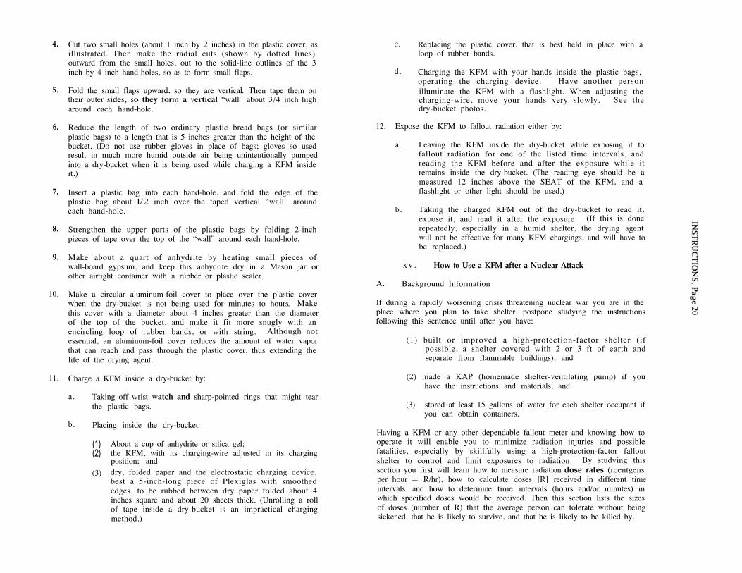
Cut two small holes (about 1 inch by 2 inches) in the plastic cover, asillustrated. Then make the radial cuts (shown by dotted lines)outward from the small holes, out to the solid-line outlines of the 3inch by 4 inch hand-holes, so as to form small flaps.
Fold the small flaps upward, so they are vertical. Then tape them ontheir outer sides, so they form a vertical “wall” about 3/4 inch higharound each hand-hole.
Reduce the length of two ordinary plastic bread bags (or similarplastic bags) to a length that is 5 inches greater than the height of thebucket. (Do not use rubber gloves in place of bags; gloves so usedresult in much more humid outside air being unintentionally pumpedinto a dry-bucket when it is being used while charging a KFM insideit.)
Insert a plastic bag into each hand-hole, and fold the edge of theplastic bag about l/2 inch over the taped vertical “wall” aroundeach hand-hole.
Strengthen the upper parts of the plastic bags by folding 2-inchpieces of tape over the top of the “wall” around each hand-hole.
Make about a quart of anhydrite by heating small pieces ofwall-board gypsum, and keep this anhydrite dry in a Mason jar orother airtight container with a rubber or plastic sealer.
Make a circular aluminum-foil cover to place over the plastic coverwhen the dry-bucket is not being used for minutes to hours. Makethis cover with a diameter about 4 inches greater than the diameterof the top of the bucket, and make it fit more snugly with anencircling loop of rubber bands, or with string. Although notessential, an aluminum-foil cover reduces the amount of water vaporthat can reach and pass through the plastic cover, thus extending thelife of the drying agent.
Charge a KFM inside a dry-bucket by:
a. Taking off wrist watch and sharp-pointed rings that might tearthe plastic bags.
b. Placing inside the dry-bucket:
(1)(2)
(3)
About a cup of anhydrite or silica gel;the KFM, with its charging-wire adjusted in its chargingposition; and
dry, folded paper and the electrostatic charging device,best a 5-inch-long piece of Plexiglas with smoothededges, to be rubbed between dry paper folded about 4inches square and about 20 sheets thick. (Unrolling a rollof tape inside a dry-bucket is an impractical chargingmethod.)
C. Replacing the plastic cover, that is best held in place with aloop of rubber bands.
d. Charging the KFM with your hands inside the plastic bags,operating the charging device. Have another person
illuminate the KFM with a flashlight. When adjusting thecharging-wire, move your hands very slowly. See thedry-bucket photos.
12. Expose the KFM to fallout radiation either by:
a. Leaving the KFM inside the dry-bucket while exposing it tofallout radiation for one of the listed time intervals, andreading the KFM before and after the exposure while itremains inside the dry-bucket. (The reading eye should be ameasured 12 inches above the SEAT of the KFM, and aflashlight or other light should be used.)
b. Taking the charged KFM out of the dry-bucket to read it,expose it, and read it after the exposure. (If this is done
repeatedly, especially in a humid shelter, the drying agentwill not be effective for many KFM chargings, and will have tobe replaced.)
x v . How to Use a KFM after a Nuclear Attack
A. Background Information
If during a rapidly worsening crisis threatening nuclear war you are in theplace where you plan to take shelter, postpone studying the instructionsfollowing this sentence until after you have:
(1) built or improved a high-protection-factor shelter (ifpossible, a shelter covered with 2 or 3 ft of earth andseparate from flammable buildings), and
(2) made a KAP (homemade shelter-ventilating pump) if youhave the instructions and materials, and
(3) stored at least 15 gallons of water for each shelter occupant ifyou can obtain containers.
Having a KFM or any other dependable fallout meter and knowing how tooperate it will enable you to minimize radiation injuries and possiblefatalities, especially by skillfully using a high-protection-factor falloutshelter to control and limit exposures to radiation. By studying thissection you first will learn how to measure radiation dose rates (roentgensper hour = R/hr), how to calculate doses [R] received in different timeintervals, and how to determine time intervals (hours and/or minutes) inwhich specified doses would be received. Then this section lists the sizesof doses (number of R) that the average person can tolerate without beingsickened, that he is likely to survive, and that he is likely to be killed by.
Most fortunately for the future of all living things, the decay ofradioactivity causes the sandlike fallout particles to become less and lessdangerous with the passage of time. Each fallout particle acts much like atiny X ray machine would if it were made so that its rays, shooting outfrom it like invisible light, became weaker and weaker with time.
Contrary to exaggerated accounts of fallout dangers, the radiation doserate from fallout particles when they reach the ground in the areas of theheaviest fallout will decrease quite rapidly. For example, consider thedecay of fallout from a relatively nearby, large surface burst, at a placewhere the fallout particles are deposited on the ground one hour after theexplosion. At this time one hour after the explosion, assume that theradiation dose rate (the best measure of radiation danger at a particulartime) measures 2,000 roentgens per hour (2,000 R/hr) outdoors. Sevenhours later the dose rate is reduced to 200 R/hr by normal radioactivedecay. Two days after the explosion, the dose rate outdoors is reduced byradioactive decay to 20 R/hr. After two weeks, the dose rate is less than 2R/hr. When the dose rate is 2 R/hr, people can go out of a good shelterand work outdoors for 3 hours a day, receiving a daily dose of 6 roentgens,without being sickened.
In places where fallout arrives several hours after the explosion, theradioactivity of the fallout will have gone through its time period of mostrapid decay while the fallout particles were still airborne. If you are in alocation so distant from the explosion that fallout arrives 8 hours after theexplosion, two days must pass before the initial dose rate measured atyour location will decay to 1/10 its initial intensity.
B. Finding the Dose Rate
1. Reread Section IV, “What a KFM Is and How It Works. ”Also reread Section XIII, “Two Ways to Charge a KFM,”and actually do each step immediately after reading it.
2. Charge the KFM, raise the lower end of its charging-wireand read the apparent separation of the lower edges of itsleaves while the KFM rests on an approximately horizontalsurface. Never take a reading while a leaf is touching astop-thread.
3. Expose the KFM to fallout radiation for one of the timeintervals shown in the vertical columns of the table attachedto the KFM. (Study the following table.) If the dose rate isnot known even approximately, first expose the fullycharged KFM for one minute. For dependablemeasurements outdoors, expose the charged KFM aboutthree feet above the ground. For most exposures, connectthe KFM to a stick or pole (best done with two rubberbands), and expose it about three feet above the ground. Becareful not to tilt the KFM too much.
4.
5.
6.
7.
8.
9.
Read the KFM after the exposure, while the KFM rests onan approximately horizontal surface.
Find the time interval that gives a dependable reading -- byexposing the fully charged KFM for one or more of the listedtime intervals until the reading after the exposure is:
(a)
(b)
Not less than 5 mm.
At least 2 mm less than the reading before theexposure.
Calculate by simple subtraction the difference in theapparent separation of the lower edges of the leaves beforethe exposure and after the exposure. An example: If thereading before the exposure is 18 mm and the reading afterthe exposure is 6 mm, the difference in readings is 18mm -6 mm = 12 mm.
If an exposure results in a difference in readings of less than2 mm, recharge the KFM and expose it again for one of thelonger time intervals listed. (If there appears to be nodifference in the readings taken before and after anexposure for one minute, this does not prove there isabsolutely no fallout danger.)
If an exposure results in the reading after the exposurebeing less than 5 mm, recharge the KFM and expose itagain for one of the shorter time intervals listed.
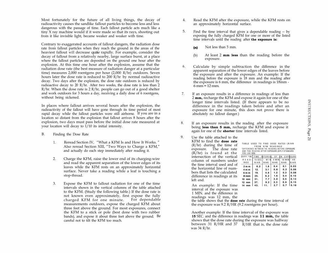
Use the table attached to theKFM to find the dose rate(R/hr) during the time ofexposure. The dose rate(R/hr) i s found at the
T A B L E U S E D T O F I N D D O S E R A T E S ( R / H RF R O M K F M R E A D I N G S
*D I F F E R E N C E B E T W E E N T H E R E A D l N G B E F O R E EXPOSUREA N D T H E R E A D I N G A F T E R EXPOSURE (8-PLY ST A NDARDF OlL LEA VES)
DIF F.*IN T I M E I N T E R V A L O F A N E X P O S U R E
R E A D - 1 5 S E C. 1 M I N 4 MIN 16 MIN 1 H RI N G S R / H R R/H R R/H R R/H R R / H R
2 m m 6.2 1.6 0.4 0.1 0 .03
4 m m 12. 3.1 0 .8 0 .2 0 .06
6 m m 19. 4 .6 1.2 0.3 0 .08
8 mm 25. 6 .2 1.6 0.4 0 .10
10 mm 31. 7 .7 2 .0 0.5 0 .13
12 mm 37. 9 .2 2.3 0 .6 0 .15
14 mm 43. 11. 2.7 0 .7 0 .18
intersection of the verticalcolumn of numbers underthe time interval used and ofthe horizontal line of num-bers that lists the calculateddifference in readings at itsleft end.
An example: If the timeinterval of the exposure was1 MIN. and the difference inreadings was 12 mm, thethe table shows that the dose rate during the time interval ofthe exposure was 9.2 R/HR (9.2 roentgens per hour).
Another example: If the time interval of the exposure was15 SEC. and the difference in readings was 11 mm, the tableshows that the dose rate during the exposure was halfwaybetween 31 R/HR and 37 R/HR that is, the dose ratewas 34 R/hr.
10.
11.
Note in the table that if an exposure for one of the listed timeintervals causes the difference in readings to be 2 mm or 3mm, then an exposure 4 times as long reveals the same doserate. An example: If a l - min exposure results in adifference in readings of 2 mm, the table shows the dose ratewas 1.6 R/hr; then if the KFM is exposed for 4 minutes atthis same dose rate of 1.6 R/hr, the table shows that theresultant difference in readings is 8 mm.
T h e l o n g e r e x p o s u r e r e s u l t s i n a m o r e a c c u r a t edetermination of the dose rate.
If the dose rate is found to be greater than 0.2 R/hr and timeis available, recharge the KFM and repeat the dose-ratemeasurement -- to avoid possible mistakes.
C. Calculating the Dose Received
The dose of fallout radiation -- that is, the amount of fallout radiationreceived -- determines the harmful effects on men and animals. Beingexposed to a high dose rate is not always dangerous -- provided theexposure is short enough to result in only a small dose being received. Forexample, if the dose rate outside an excellent fallout shelter is 1200 R/hrand a shelter occupant goes outside for 30 seconds, he would be exposedfor 1/2 of 1 minute, or 1/2 of 1/60 of an hour, which equals 1/120 hour.Therefore, since the dose he would receive if he stayed outside for 1 hourwould be 1200 R, in 30 seconds he would receive l/l20 of 1200, whichequals 10 R (1200 R divided by 120 = 10 R). A total daily dose of 10 R (10roentgens) will not cause any symptoms if it is not repeated day after dayfor a week or more.
In contrast, if the average dose rate of an area were found to be 12 R/hrand if a person remained exposed in that particular area for 24 hours, hewould receive a dose of 288 R (12 R/hr x 24 hr = 288 R). Even assumingthat this person had been exposed previously to very little radiation, therewould still be a serious risk that this 288 R dose would be fatal under thedifficult conditions that would follow a heavy nuclear attack.
Another example: Assume that three days after an attack the occupantsof a dry, hot cave giving almost complete protection against fallout are indesperate need of water. The dose rate outside is found to be 20 R/hr. Tobackpack water from a source 3 miles away is estimated to take 2-1/2hours. The cave occupants estimate that the water backpackers willreceive a dose in 2-1/2 hours of 50 R (2.5 hr x 20 R/hr = 50 R). A dose of50 R will cause only mild symptoms (nausea in about 10% of personsreceiving a 50 R dose) for persons who previously have received only verysmall doses. Therefore, one of the cave occupants makes a rapid radiationsurvey for about 1-1/2 miles along the proposed route, stopping to chargeand read a KFM about every quarter of a mile. He finds no dose ratesmuch higher than 20 R/hr. ,
So, the cave occupants decide the risk is small enough to justify some ofthem leaving shelter for about 2-1/2 hours to get water.
D. Estimating the Dangers from Different Radiation Doses
Fortunately, the human body -- if given enough time -- can repair most ofthe damage caused by radiation. An historic example: A healthy man
2
accidently received a daily dose of 9.3 R (or somewhat more) of2
fallout-type radiation each day for a period of 106 days. His total2
accumulated dose was at least 1000 R. A dose of one thousand roentgens, 3
if received in a few days, is almost three times the dose likely to kill theaverage man if he receives the whole dose in a few days and after a
E_m
nuclear attack cannot get medical treatment, adequate rest, etc.However, the only symptom this man noted was serious fatigue.
7w
The occupants of a high-protection-factor shelter (such as a trench sheltercovered with 2 or 3 feet of earth and having crawlway entrances) wouldreceive less than 1/200 of the radiation dose they would receive outside.Even in most areas of very heavy fallout, persons who remain continouslyin such a shelter would receive a total accumulated dose of less than 25 Rin the first day after the attack, and less than 100 R in the first two weeks.At the end of the first two weeks, such shelter occupants could startworking outside for an increasing length of time each day, receiving adaily dose of no more than 6 R for up to two months without beingsickened.
M
To control radiation exposure in this way, each shelter must have a falloutmeter, and a daily record must be kept of the approximate total dosereceived each day by every shelter occupant, both while inside and outsidethe shelter. The long-term penalty which would result from a dose of 100R received within a few weeks is much less than many Americans fear. If100 average persons received an external dose of 100 R during and shortlyafter a nuclear attack, the studies of the Japanese A-bomb survivorsindicate that no more than one of them is likely to die during the following30 years as a result of this 100 R radiation dose. These delayed radiationdeaths would be due to leukemia and other cancers. In the desperatecrisis period following a major nuclear attack, such a relatively smallshortening of life expectancy during the following 30 years should notkeep people from starting recovery work to save themselves and theirfellow citizens from death due to lack of food and other essentials.
A healthy person who previously has received a total accumulated dose ofno more than 100 R distributed over a 2-week period should realize that:
100 R, even if all received in a day or less, is unlikely to requiremedical care--provided during the next 2 weeks a total additionaldose of no more than a few R is received.
350 R received in a few days or less is likely to prove fatal after a largenuclear attack when few survivors could get medical care, sanitarysurroundings, a well-balanced diet, or adequate rest.
600 R received in a few days or less is almost certain to cause deathwithin a few days.
E. Using a KFM to Reduce the Doses Received Inside a Shelter
Inside most shelters, the dose received by an occupant variesconsiderably, depending on the occupant’s location. For example, insidean expedient covered-trench shelter the dose rate is higher near theentrance than in the middle of the trench. In a typical basement shelterthe best protection is found in one corner. Especially during the firstseveral hours after the arrival of fallout, when the dose rates and dosesreceived are highest, shelter occupants should use their fallout meters todetermine where to place themselves to minimize the doses they receive.They should use available tools and materials to reduce the doses theyreceive, especially during the first day, by digging deeper (if practical1and reducing the size of openings by partially blocking them with earth,water containers, etc. -- while maintaining adequate ventilation. Togreatly reduce the danger from fallout particles entering the body throughnose or mouth, shelter occupants should at least cover their nose andmouth with a towel or other cloth while the fallout is being depositedoutside their shelter.
The air inside an occupied shelter often becomes very humid. If a good gflow of outdoor air is flowing into a shelter -- especially if pumped bybriefly operating a KAP or other ventilating pump -- a KFM usually can be
g
charged at the air intake of the shelter room without putting it inside a2
dry-bucket. However, if the air to which a KFM is exposed has a relative s
humidity of 90% or higher, the instrument cannot be charged, even by _gquickly unrolling a roll of tape. 7
auIn extensive areas of heavy fallout, the occupants of most home Lbasements, that provide inadequate shielding against heavy fallout wradiation, would be in deadly danger. By using a dependable falloutmeter, occupants would find that persons lying on the floor in certainlocations would receive the smallest doses, and that, if they improviseadditional shielding in these locations, the doses received could be greatlyreduced. Additional shielding can be provided by placing a double layerof doors, positioned about two feet above the floor and strongly supportednear their ends, and by putting books, containers full of water and otherheavy objects on top of these doors. Or, if tools are available, breakingthrough the basement floor and digging a shelter trench will greatlyincrease available protection against radiation. If a second expedientventilating pump, a KAP, is made and used as a fan, such an extremely
cramped shelter inside a shelter usually can be occupied by several timesas many persons.
END OF INSTRUCTIONS