Embed Size (px)
Citation preview

Excellent Treatment
PD0313-7 AUGUST 2005
PAGE 1
INSTALLATION, OPERATING & MAINTENANCE GUIDELINES FOR CLASS 1 AND CLASS 2
BYPASS SEPARATORS This manual covers the following equipment
NSB 3-NSB 18
HEALTH & SAFETY
These warnings are provided in the interest of safety. You must read them carefully before installing or using the equipment. It is important that this document is retained with the equipment for future reference. Should the equipment be transferred to a new owner, always ensure that all relevant documents are supplied in order that the new owner can be acquainted with the functioning of the equipment and the relevant warnings.
Installation should only be carried out by a suitably experienced contractor, following these guidelines.
We recommend the use of a dust mask and gloves when cutting GRP components.
Electrical work should be carried out by a qualified electrician.
Contaminated surface water can contain substances harmful to human health. Any person carrying out maintenance on the equipment should wear suitable protective clothing, including gloves. Good hygiene practice should also be observed.
Access covers should be selected with reference to the location of the unit and traffic loads to be accommodated. These are not (normally) part of the Separator supply.
When covers are removed precautions must be taken against personnel falling into the unit.
Should you wish to inspect the operation of the equipment, please observe all necessary precautions, including those listed below, which apply to maintenance procedures.
Ensure that you are familiar with the safe working areas and accesses. Ensure that the working area is adequately lit.
Take care to maintain correct posture, particularly when lifting. Use appropriate lifting equipment when necessary. Keep proper footing and balance at all times. Avoid any sharp edges.
OIL ALARM SYSTEMS PPG3 recommends that that the oil level alarm be fitted, tested and commissioned by a competent Installer This is to ensure that the excessive oil probe is calibrated correctly, raising an alarm when 90% of the recommended maximum oil storage volume is reached. Should the oil level alarm fail to provide an early warning, excessive oil could pass through the separator, thus polluting the environment. This could result in substantial cleanup costs and legal action being taken under the water resources act 1991.
MAINTENANCE The correct ongoing maintenance is essential for the proper operation of the equipment. Operators who rely on oil level alarms to prompt them to service separators between maintenance intervals run the risk of polluting should the alarms not work, hence the ongoing functional assessment of the oil alarm systems is fundamental if pollution incidents are to be avoided. The removal of sediment and retained oil/grease should be carried out by a contractor holding the relevant permits to transport and dispose of such waste. The contractor must refer to the guidelines in this document.
Klargester Environmental
College Road North, Aston Clinton, Aylesbury, Buckinghamshire, HP22 5EW
Tel: +44 (0) 1296 633033 Fax: +44 (0) 1296 633001
Website: www.klargester.com Email: [email protected]

PD0313-7 AUGUST 2005
PAGE 2
CONTENTS Page
Health & Safety..........................................................................................................................................1
1. Introduction..........................................................................................................................................2
2. Handling & Storage..............................................................................................................................2
3. Site Planning .......................................................................................................................................3
4. Installation - General............................................................................................................................3
Concrete Specification........................................................................................................................4
5. Separator Installation...........................................................................................................................4
6. Alarm Installation................................................................................................................................. 5
7. Operation.............................................................................................................................................6
8. Maintenance........................................................................................................................................6
9. Emergencies........................................................................................................................................8
Appendices Separator Maintenance Log
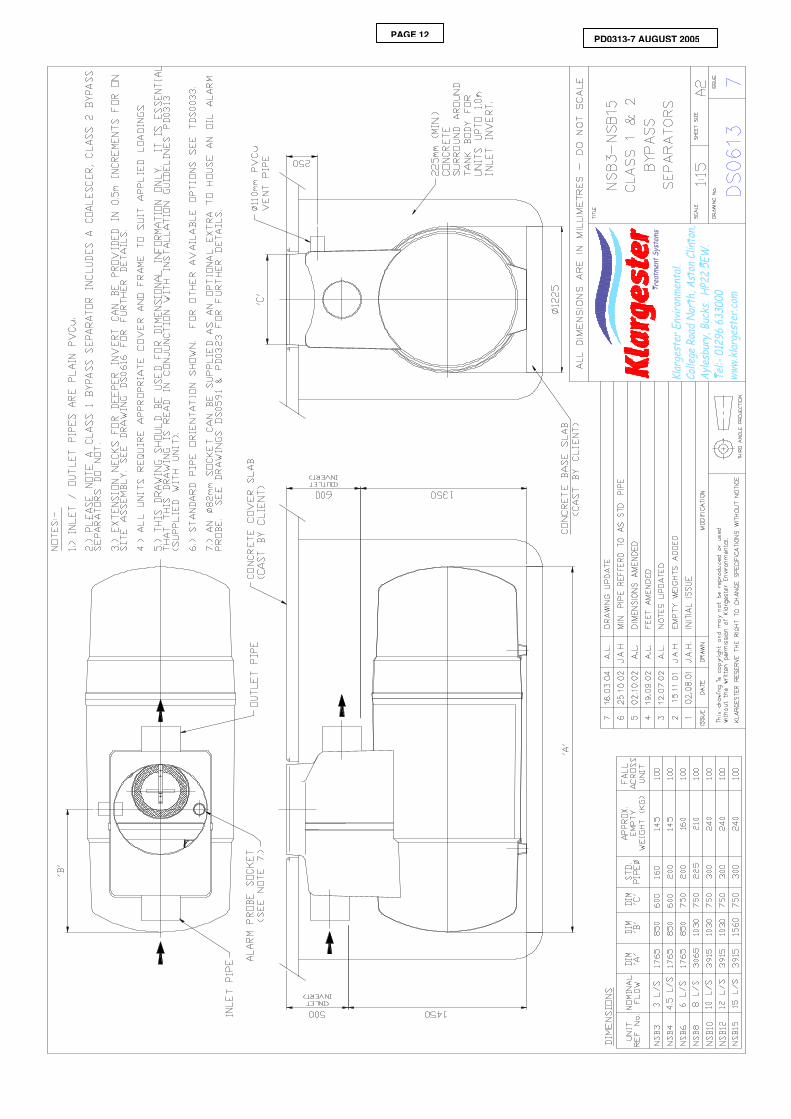
NSB 3-15 Drawing No. DS0613
Extension & Handle Fitting Details Drawing No. DS0616
Normal and Bypass Flow routes Drawing No. DS0560 & DS0561
Oil probe-fitting details
1.0 Introduction These Guidelines represent Best Practice for the installation of the above Klargester Separator Units. Many years of specialist experience has led to the successful installation of thousands of separator units. It must be noted, however, that these Guidelines are necessarily of a general nature. It is the responsibility of others to verify that they are appropriate for the specific ground conditions and in-service loads of each installation. Similarly, any information or advice given by employees or agents of Klargester regarding the design of an installation must be verified by a qualified specialist (e.g. Civil engineering consultant).
For guidance of Separator selection and application, please refer to the most recent issue of Environment Agency Guidelines pollution prevention guidelines No. 3 (PPG3).and En 858 A range of our units has been independently tested by the British Standard Institute and certified as meeting the PPG3 guidelines
2.0 Handling & Storage 2.1. Care must be taken to ensure that units are not damaged during delivery and handling on site.
Please take care and place unit so that it cannot fall and become damaged
2.2. The design requirements of Klargester products will frequently mean that the centre of gravity of the unit is “offset”. Care must therefore be taken to ensure that the unit is stable when lifting. Rainwater may also collect inside units, particularly if they have been stored on site prior to installation, adding weight and increasing instability. Check units before lifting and pump out any excess water.
2.3. When lifting units, use webbing slings of a suitable specification. Do not use chains.
2.4. A suitable spreader bar should be used to ensure that units are stable and that loads are evenly distributed during lifting. When lifting separators, a spreader bar should be used where the slings would otherwise be at an angle > 30 degrees to the vertical.
2.5. Lifting equipment should be selected by taking into account the unit weight, length and the distance of lift required on site.
2.6. Klargester Environmental accepts no responsibility for the selection of lifting equipment.
2.7. Whenever Klargester units are stored or moved on site, ensure that the storage location is free of rock, debris and any sharp objects, which may damage the unit. The units must be placed on ground, which is flat, and level and the unit orientated onto its side with even support. Do not roll separators.

PD0313-7 AUGUST 2005
PAGE 3
3.0 Site Planning The following points should be considered before installation of the equipment:
3.1. The discharge must have the consent of the relevant Environmental Regulator.
3.2. The installation should have Planning and Building Control approval.
3.3. Consider installing flow cut-off valves to isolate the separator in an emergency or during site cleaning operations. See Environment Agency Guidelines PPG3.
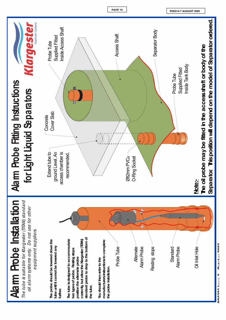
3.4. When requested at the time of purchase, Klargester will fit a tube to receive the alarm probe. This tube provides protection and ensures that the probe is positioned at the correct level to sense the oil build up. The tube design and probe level setting assumes the use of Klargester standard oil alarm system and may not be suitable for other alarm supplier’s equipment. The probe tube may be fitted either within the neck or within the body of the unit. It should be extended to ground level when fitted in the body of the tank and you should make provision to extend the tube to the required height before backfilling. Consult the alarm supplier’s instructions for they’re detailed fitting installation instructions.
3.5. Consider installation of a sampling point downstream of the separator. There is no suitable facility to effectively sample the wastewater from inside the unit. EN 858 Pt 1.
3.6. Uncontaminated run off such as roof water should be excluded from separators. (EA Guidelines PPG3.)
3.7. Ground conditions and water table level should be assessed. If the water table will be above the base of the units at any time of the year, adequate concrete backfill must be provided to avoid flotation. In poorly draining ground, consideration should also be given to the likelihood of flotation due to surface water collecting in the backfill, and an appropriate installation method devised to avoid this.
3.8. If the discharge is to a soakaway, a porosity test should be carried out as part of the assessment of suitability for sub-soil drainage.
3.9. The separator must be installed at a level, which will allow connection to the incoming drain and a free discharge at the system outlet. The water table must be below the discharge outlet.
3.10. Do not install the unit deeper than necessary, ensure that you purchase extension shafts and handles. The minimum invert depth of the unit is shown on the customer drawing.
3.11. Adequate access must be provided for routine maintenance. Vehicles should not be permitted within a distance equal to the depth of the unit, unless suitable structural protection is provided to the installation.
3.12. There must be at least 1 metre of clear, level ground all around the access covers to allow for routine maintenance.
3.13. It is essential that a mains water supply is accessible for routine cleansing and refilling after removal of waste material and liquid.
3.14. Provide electrical supply for alarm system. (If required)
3.15. Installation should only be carried out by suitably qualified and experienced contractors in accordance with current Health and Safety Regulations. Electrical work should be carried out by a qualified electrician, working to the latest edition of IEE.
4.0 Installation – General 4.1. When units are installed in unstable ground conditions where movement of the surrounding material
and/or unit may occur, the connecting pipework should be designed to minimise the risk of damage from differential movement of the unit(s) and/or surrounding material.
4.2. For separators with burial depths greater than 1000mm from cover level to the top of the unit, specific site conditions should be taken into consideration and the backfill designed to bear any loads which may be applied during and after installation to prevent the tank being subjected to these loads.
4.3. The excavation must be deep enough to provide bedding and cover depth as determined by the type of surface pavement and loading. Asphalt and concrete pads should extend a minimum of 300mm horizontally beyond the unit in all directions.
4.4. In situations where the excavation will not maintain a vertical wall, it will be necessary to shore up the sidewalks of the excavation with suitable trench sheets and bracing systems to maintain a vertical wall from the bottom to the top of the excavation. DO NOT completely remove the shoring system until the backfilling is complete, but before the concrete fully hardens.

PD0313-7 AUGUST 2005
PAGE 4
4.5. In areas where the water table is above the bottom of the excavation and/or the excavation is liable to flood, the excavation should be dewatered using suitable pumping equipment and this should continue until the installation is complete.
4.6. During installation care must be taken to ensure that the body of the unit is uniformly supported so that point loads through the unit are avoided.
4.7. Concrete Specification SK296 is a general specification. It is not a site-specific installation design.
CONCRETE SPECIFICATION SK296 IN ACCORDANCE WITH BS 5328 PARTS 1,2,3 AND 4
TYPE OF MIX DESIGN PERMITTED TYPE OF CEMENT BS 12 (OPC): BS 12 (RHPC): BS 4027 (SRPC) PERMITTED TYPE OF AGGREGATE (coarse & fine)
BS 882
NOMINAL MAXIMUM SIZE OF AGGREGATE 20 mm GRADES: GRADES: C30 (30 N/mm2)
C30 (30 N/mm2)
C20 (20 N/mm2)
REINFORCED & ABOVE GROUND WITH HOLDING DOWN BOLTS REINFORCED (EG. FOR HIGH WATER TABLE) UNREINFORCED (NORMAL CONDITIONS)
MINIMUM CEMENT CONTENT
C30 C20
270 - 280 Kg/M3 220 - 230 Kg/M3
SLUMP (NOT IN ACCORDANCE WITH BS 5328) 25mm RATE OF SAMPLING READY MIX CONCRETE SHOULD BE SUPPLIED
COMPLETE WITH APPROPRIATE DELIVERY TICKET IN ACCORDANCE WITH BS 5328 PART 3
NOTE: STANDARD MIXES SHOULD NOT BE USED WHERE SULPHATES OR OTHER AGGRESSIVE CHEMICALS EXIST IN GROUND WATER
5.0 Separator Installation 5.9. Excavate a hole of sufficient length and width to accommodate the tank and a minimum 225mm
concrete surround and to a depth, which allows for the burial depth of the unit plus concrete base slab and haunch.
5.2. Construct a suitable concrete base slab appropriate to site conditions. Ensure that the slab is flat and level.
5.3. When the concrete base slab has set enough to support the installed load, add a concrete haunch so as to provide even support under the unit, then lower the unit onto the haunch using suitable webbing slings and lifting equipment.
5.4. Pour no more than 300-mm depth of clean water into the unit, avoiding shock loads. For units with more than one chamber, add water to each chamber simultaneously. DO NOT OVERFILL, the unit is not designed to hold water whilst unsupported.
5.5. Place concrete backfill to approximately 300mm depth under and to the sides of the tank ensuring good compaction to remove voids. DO NOT use vibrating pokers. Continue adding concrete backfill, simultaneously keeping the internal water level no more than 200 mm above the backfill level at all times, until the backfill is just below the underside of the outlet drain, giving sufficient room to connect the inlet and outlet pipework.
5.6. Connect inlet and outlet drains and vent pipes when safe access to the backfill can be gained. PIPEWORK CONNECTIONS In all cases, ensure that the outlet pipework level is maintained for correct operation. (Unless specified on the order, the fall across the unit will be as per the customer drawings). Small units are generally fitted with PVCu spigots to both the outlet and the inlet. Connect using the same size PVCu socket or a suitable reducer.

PD0313-7 AUGUST 2005
PAGE 5
Larger units are generally fitted with Klargester GRP manufactured sockets. The connecting pipework should be pushed into the socket and a joint made to fill in the gap using rope/hemp with a cement mortar or bonding mix. Ensure that the seal is secure and watertight before backfilling the pipe. Alternatively, proprietary flex seal couplings can be obtained to fit over the outside of the site pipework and the outside of the GRP socket. When using this connection method, please be aware that the outside GRP laminate is not perfectly regular and that you may need to use a sealant on the outside diameter of the GRP. Take care not to over tighten the coupling when connecting to the GRP and ensure that the seal is secure before backfilling the pipe. Drawing DS0185 provides the ID of our GRP sockets. The OD is variable, as the wall thickness can be up to 15-20 mm. If purchasing a flexseal coupling for use with clay /concrete, we suggest that a size 110 mm larger than the ID is selected.
5.7. OIL LEVEL ALARM NECK FITTING When requested at the time of purchase, Klargester will fit a tube to receive the oil alarm probe. This provides protection and ensures that the probe is positioned at the correct level to sense oil build up. The probe level is set assuming Klargester standard supply alarm equipment. Adjust for alternative alarm equipment.
5.8. See alarm supplier information and ensure that the probe is placed within the tube and can be accessed from ground level.
5.9. Continue backfilling with concrete over the tank body to the required level. Build up a shell of concrete, minimum 225mm thick, around the access shaft(s). Temporarily strut the access shaft to avoid distortion.
5.10. Where Klargester supply an extension shaft to meet a deeper invert requirement, a coalescer extension handle is also provided with the shaft for Class 1 units. If there is a coalescer, remove it from the unit before adding the extension shaft. Remove the pre-fitted handle, add the extension piece and replace the handle, bolting it securely in place. Replace the handle so that it can be bolted near to the top of the extension neck. When refitting, ensure that the coalescer tube is correctly pushed onto the base fitting. Class 2 units do not require an extension handle.
5.11. It is advisable to seal the joints on the extension shafts (particularly on sites with high ground water) with proprietary sealant or by GRP lamination. Temporarily strut the extension neck(s) to avoid distortion during back filling. Where more than one neck section is required to suit a deep invert, consider back-filling section by section. If the extension neck is too long, it can be trimmed using a fine-toothed saw. The original fixing hole bolting the coalsecer in place to the neck should be sealed.
5.12. Ensure that the vent socket if cut out, is replaced elsewhere. The maximum recommended inlet invert is 2000mm (using 500mm long extension sections). If you are installing a unit deeper than this then you must make your own arrangements for removing and replacing the coalescer. Consideration must be given to the depth of lift involved.
5.13. Continue back-filling, ensuring minimum 225mm concrete thickness around the access shaft/ extension neck and alarm access tube (as applicable).
5.14. Mains powered Alarm Systems. See alarm suppliers installation instructions. Lay 82mm diameter PVCu underground ducting between the alarm panel location and the alarm probe position. The ducting should be 500mm below ground level and fitted with a drawstring for later cable insertion. Any changes of direction should be by long radius bend. If necessary, drill a suitable hole in the access shaft adjacent to the alarm probe terminal box, to accept the ducting. Seal.
5.15. In traffic areas a suitable top slab must be constructed. The top slab should bear on a suitable foundation to prevent superimposed loads being transmitted to the unit and access shafts. Loads applied to covers and frames must bear on the top slab, not the access shaft.
5.16. The unit should be filled with clean water up to the invert level of the outlet pipe. Ensure the unit identification is placed/ marked inside the neck for future information. The unit is now ready for use.

PD0313-7 AUGUST 2005
PAGE 6
6.0 Alarm Installation 6.1 Install the alarm probe and control panel, as per the Suppliers Alarm Installation Guidelines. Ensure
that the probe is positioned correctly for the required storage of oil. The table below indicates the maximum volume of oil to be stored and the depth of floating oil expected in the separation chamber.
Unit Recommended Maximum Oil Storage volume litres
Max. (100%)Depth of floating oil (Static)
NSB3 45 litres 205mm
NSB4.5 60 litres 230mm
NSB6 90 litres 270mm
NSB8 120 litres 215mm
NSB10 150 litres 220mm
NSB12 180 litres 225mm
NSB15 225 litres 280mm
NSB18 270litres 145mm
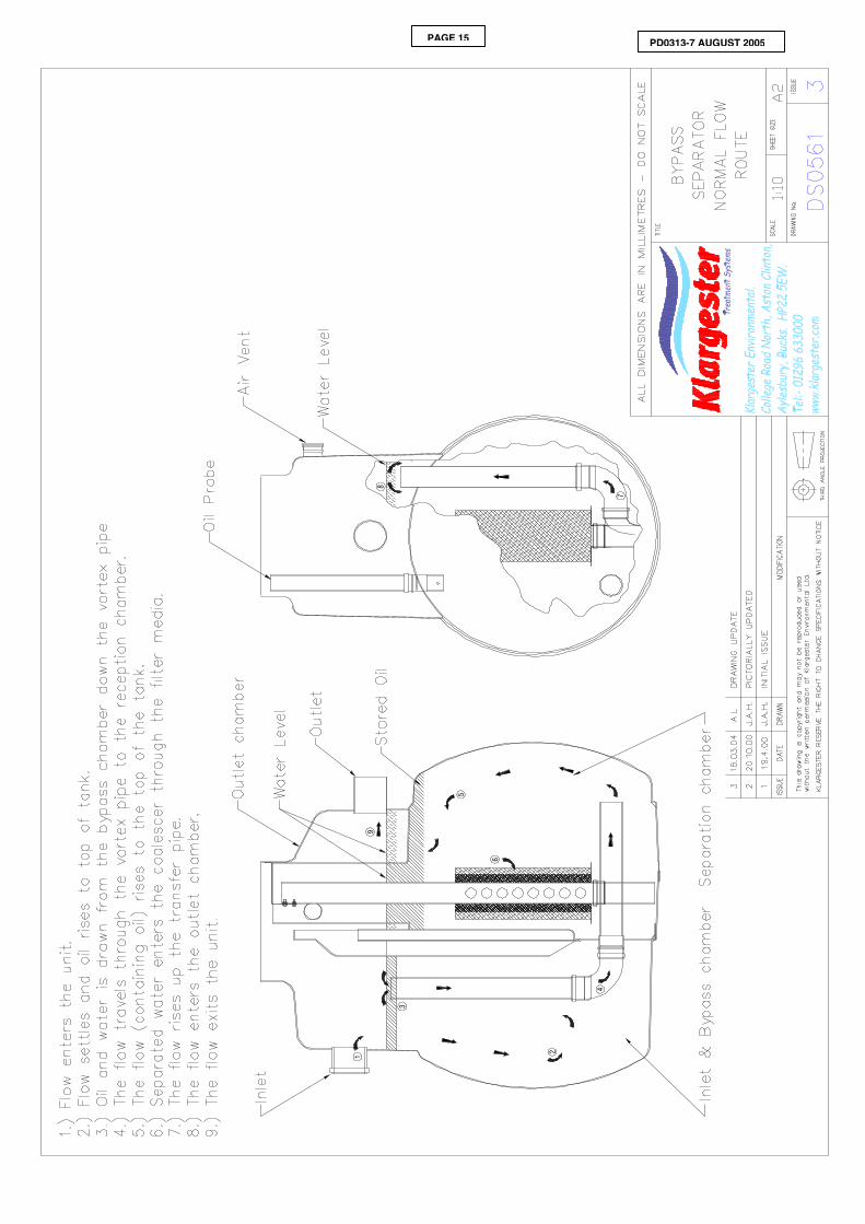
7.0 Operation The unit is sized on treating a defined area and rainfall (5 mm/hour) EN.858 Part 1 and using the factor provided in the Environment agency guidelines PPG3. The unit will treat the entire flow i.e. NSB 3 will treat a flow of 3 litres per second, If the flow is greater than this then the excess flow will bypass the main treatment chamber. A NSB 3 unit will work in bypass mode over 3 and up to 30 litres per second. Flows in excess of this will back up on to the site. During a storm, the rain falls and flushes any surface debris, silt or oil into the tank. This first flush, up to the maximum rated flow is fully treated. As the severity of the storm increases, so does the rate of flow increase. The liquid entering the separator after the first flush tends to be cleaner and so, in less risky applications is allowed to bypass the oil separation chamber for directly discharge.
7.1 The bypass unit has three chambers. The entire flow up to the units listed flow rating is fully treated and passes through all chambers. (E.g. NSB 3 treats 3 litres per second.)
7.2 Flows in excess of this rating will bypass the separation chamber and the liquid passes untreated to the outlet chamber.
7.3 The first chamber will accumulate silt and grit. The maximum volume that can be retained is the rating x 100 e.g. a NSB 003 is capable of holding 300 litres of silt.
7.4 The second / separating chamber is sized to separate oil at the rated flow rate and to accumulate the required oil storage volume. A NSB 3 maximum oil storage volume is 45 litres. An oil probe can be positioned which will detect the accumulation of oil when there is no or low flow conditions. The probe should be positioned so that the alarm operates at 90% of the rated oil storage volume.
7.5 In bypass flow conditions, the flow moves directly from the inlet to the outlet chamber avoiding the separating chamber.
7.6 Separators can be purchased either as Class 2, or as Class 1. A Class 1 Bypass Separator is fitted with a removable coalescer which also includes media to further improve the discharge quality. The coalescer media requires maintenance.
7.7 Bypass Class 1 & Class 2 Separators are not effective for the removal of soluble or emulsified pollutants such as oil/detergent mixes found in vehicle wash effluents. With permission such discharges should be drained to the foul sewer. Consult Klargester technical department for Separation equipment to meet these applications.
7.8 See drawings, which indicate the flow route of normal and bypass flow conditions.

PD0313-7 AUGUST 2005
PAGE 7
8.0 Maintenance Waste Removal and Servicing 8.1. Separated light liquid must be removed from separator when the oil capacity has been reached.
8.2. An oil level alarm system is available for purchase which gives warning when the separated light liquid/water interface level reaches 90% of the maximum recommended oil storage volume.
8.3. Separators should be inspected at least every six months or more frequently if experience dictates. A log should be maintained detailing the depth of oil found, any oil volume removed and any silt removal or cleaning carried out. A specimen maintenance log is included in the appendices.
8.4. Every site is different, in respect to the amount and type of silt generated by the drain design and installation. Frequently, the construction programme itself generates large and perhaps unusual quantities of silt and grit. We do recommend that following the initial installation, an inspection of the separator contents be made to check that building rubble has not entered the unit. Further inspections at 3 and 6 months should be made so as to be able to assess the volumes of silt and oil accumulated. The inspection and emptying programme can then be defined following the first 6 months site experience. We recommend leaving a maximum interval between inspections of 6 months.
8.5. Alarm probes should be removed and cleaned with water whenever waste material is removed from the separator. Please note the alarm may alert until the liquid level is replaced.
8.6. Separator waste is a “special waste” under the terms of The Waste Management Code of Practice. The Code imposes a duty of care on the waste producer to ensure that the Cleansing contractor is registered with the Environment Agency and that the final disposal of the waste is to a licensed facility.
8.7. You should consider the purchase of a maintenance service, which includes bi-annual inspections, removal of oil and silt, cleaning of the alarm probe and cleaning or replacement of the coalescer (where appropriate).
Waste Removal Procedure – Oil & Silt Oil can only be effectively removed when there is no flow entering the unit. Isolate the unit and prevent flow from entering. Always remove the oil before attempting to remove the coalescer. If this is not done, when the coalescer is withdrawn the oil can coat the media surface and when replaced the oil may be forced through the media, contaminating the effluent. 8.8. Remove the access cover and lower the desludging hose in to the separation chamber. Draw off the
surface oil. 8.9. Lower the desludging hose to the base of the tank and withdraw any grit or sludge that may be
present. Do not remove more water than is necessary. Ensure that you access and clean both compartments.
8.10. Remove the alarm probe, if fitted, clean with water and replace. 8.11. Consider the period of time that the coalescer has been installed and consider removing and
inspecting (cleaning or replacing) the coalescer media. If removed, ensure that it is correctly replaced and secured into position. Replace the access covers. It is best to lower the water level to aid re-fitting.
8.12. Re-fill the separator with clean water up to the outlet level. If an alarm is fitted, it will display an alarm condition until the separator is re-filled. Check alarm operation when unit full.
Checking the Coalescer Assembly 8.13. Coalescers, where fitted, may be cleaned periodically to maintain efficiency. Coalescers should be
checked following a major incident and replaced if necessary. Please contact Klargester if you wish to purchase the coalescer media.
8.14. Identify the type and size of separator (shown on labels inside the access neck). 8.15. Assemblies weighing less than 25 Kg may be removed by hand. Heavier assemblies should be lifted
by mechanical means. Any lifting device employed must be capable of lifting:
• In excess of the maximum assembly weight.
• The assembly completely out of the access shaft.
PD0313-7 AUGUST 2005
PAGE 8
• Giving a smooth and controlled lift.
• Swinging the assembly to one side clear of the access shaft.
PD0313-7 AUGUST 2005
PAGE 9
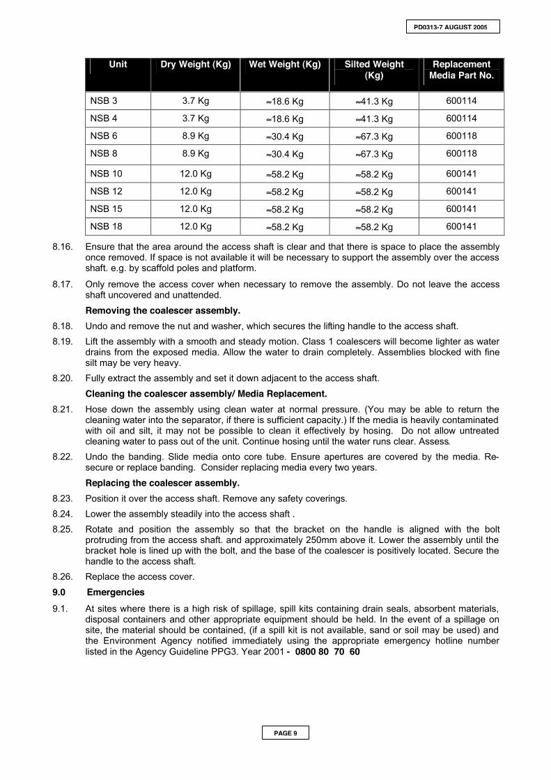
Unit Dry Weight (Kg) Wet Weight (Kg) Silted Weight (Kg)
Replacement Media Part No.
NSB 3 3.7 Kg ≈18.6 Kg ≈41.3 Kg 600114
NSB 4 3.7 Kg ≈18.6 Kg ≈41.3 Kg 600114
NSB 6 8.9 Kg ≈30.4 Kg ≈67.3 Kg 600118
NSB 8 8.9 Kg ≈30.4 Kg ≈67.3 Kg 600118
NSB 10 12.0 Kg ≈58.2 Kg ≈58.2 Kg 600141
NSB 12 12.0 Kg ≈58.2 Kg ≈58.2 Kg 600141
NSB 15 12.0 Kg ≈58.2 Kg ≈58.2 Kg 600141
NSB 18 12.0 Kg ≈58.2 Kg ≈58.2 Kg 600141
8.16. Ensure that the area around the access shaft is clear and that there is space to place the assembly once removed. If space is not available it will be necessary to support the assembly over the access shaft. e.g. by scaffold poles and platform.
8.17. Only remove the access cover when necessary to remove the assembly. Do not leave the access shaft uncovered and unattended.
Removing the coalescer assembly. 8.18. Undo and remove the nut and washer, which secures the lifting handle to the access shaft. 8.19. Lift the assembly with a smooth and steady motion. Class 1 coalescers will become lighter as water
drains from the exposed media. Allow the water to drain completely. Assemblies blocked with fine silt may be very heavy.
8.20. Fully extract the assembly and set it down adjacent to the access shaft.
Cleaning the coalescer assembly/ Media Replacement. 8.21. Hose down the assembly using clean water at normal pressure. (You may be able to return the
cleaning water into the separator, if there is sufficient capacity.) If the media is heavily contaminated with oil and silt, it may not be possible to clean it effectively by hosing. Do not allow untreated cleaning water to pass out of the unit. Continue hosing until the water runs clear. Assess.
8.22. Undo the banding. Slide media onto core tube. Ensure apertures are covered by the media. Re-secure or replace banding. Consider replacing media every two years.
Replacing the coalescer assembly. 8.23. Position it over the access shaft. Remove any safety coverings. 8.24. Lower the assembly steadily into the access shaft . 8.25. Rotate and position the assembly so that the bracket on the handle is aligned with the bolt
protruding from the access shaft. and approximately 250mm above it. Lower the assembly until the bracket hole is lined up with the bolt, and the base of the coalescer is positively located. Secure the handle to the access shaft.
8.26. Replace the access cover.
9.0 Emergencies 9.1. At sites where there is a high risk of spillage, spill kits containing drain seals, absorbent materials,
disposal containers and other appropriate equipment should be held. In the event of a spillage on site, the material should be contained, (if a spill kit is not available, sand or soil may be used) and the Environment Agency notified immediately using the appropriate emergency hotline number listed in the Agency Guideline PPG3. Year 2001 - 0800 80 70 60
PAGE 10 PD0313-7 AUGUST 2005
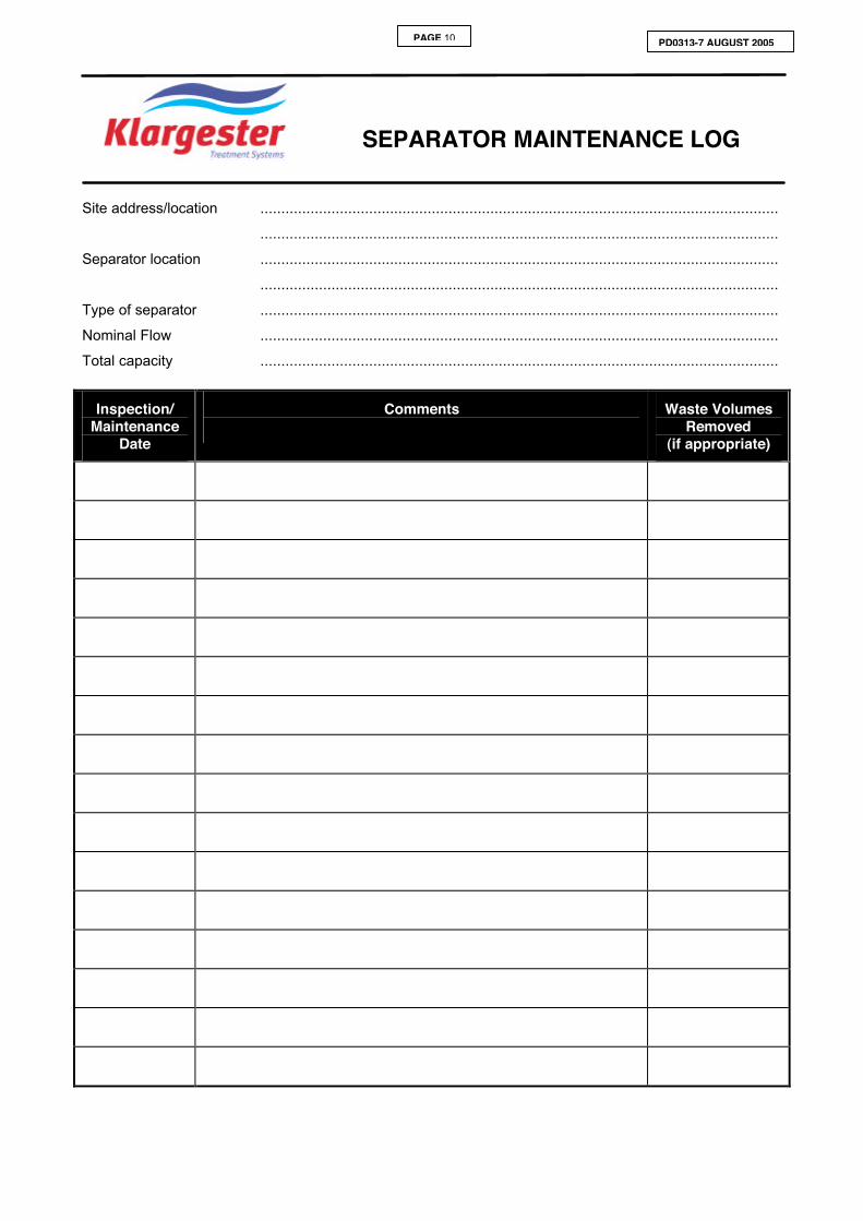
SEPARATOR MAINTENANCE LOG
Site address/location ............................................................................................................................
............................................................................................................................
Separator location ............................................................................................................................
............................................................................................................................
Type of separator ............................................................................................................................
Nominal Flow ............................................................................................................................
Total capacity ............................................................................................................................
Inspection/ Maintenance
Date
Comments
Waste Volumes Removed
(if appropriate)

PAGE 11 PD0313-7 AUGUST 2005
PAGE 12 PD0313-7 AUGUST 2005

PAGE 13 PD0313-7 AUGUST 2005
750

PAGE 14 PD0313-7 AUGUST 2005
34
2
1
PAGE 15 PD0313-7 AUGUST 2005
4
2
3
5
7
1
98
6
PAGE 16 PD0313-7 AUGUST 2005
Sepa
rator
Bod
y
Acce
ss S
haft
Prob
e Tub
eSu
pplie
d Fitte
dIns
ide A
cces
s Sha
ft
Ø82m
m PV
CuO-
Ring
Soc
ket
Exten
d tub
e to
grou
nd Le
vel. A
nac
cess
cham
ber is
reco
mme
nded
.
Alter
nate
Alar
m Pr
obe
Prob
e Tub
e
Resti
ng s
tops
Stan
dard
Alar
m Pr
obe
Oil In
let H
ole
Conc
rete
Cove
r Slab
Prob
e Tub
eSu
pplie
d Fitte
dIn
side T
ank B
ody
Note
:-Th
e oi
l pro
be m
ay b
e fit
ted
in th
e ac
cess
shaf
t or b
ody
of th
eSe
para
tor.
This
posit
ion
will d
epen
d on
the
mod
el o
f Sep
arat
or o
rder
ed.
The
prob
e sh
ould
be
lowe
red
down
the
tube
unt
il it c
anno
t be
lowe
red
any
furth
er.
The
tube
is d
esig
ned
to a
ccom
mod
ate
two
type
s of p
robe
. Re
sting
stop
s po
sitio
n th
e al
tern
ate
prob
eco
rrect
ly, b
ut a
llow
the
Klar
geste
r (TIT
AN)
stand
ard
prob
e to
dro
p to
the
botto
m o
f th
e tu
be.
You
shou
ld th
en re
fer t
o th
e m
anuf
actu
rers
instr
uctio
ns to
com
plet
e th
e pr
obe
insta
llatio
n.
The
tub
e is
sui
tabl
e fo
r Kla
rges
ter (
TITA
N) s
tand
ard
oil a
larm
sys
tem
s on
ly. D
o no
t use
for
othe
r eq
uipm
ent s
uppl
iers
.