Embed Size (px)
Citation preview

PCM100230V automation central unit
for sliding gate
ITA
LIA
NO
EMC 89/336 CEE
USER MANUALFor PCB circuits 425ama-2.00
Made in Italy
EN
GL
ISH

Index
Chapter 1 Introduction 4
1.1 Central Unit description.....................................................................................41.2 Central Unit Overview .......................................................................................41.3 Technical Features ............................................................................................4
Chapter 2 Installation 5
2.1 Board description ..............................................................................................52.2 Example of installation ......................................................................................62.3 Connections ......................................................................................................7
2.3.1 Power supply, flasher, geared-motor, controls .......................................82.3.2 Relay photocells connection ..................................................................92.3.3 Photocells with autodiagnosis connection .............................................9
3.1 Dip-switch........................................................................................................10
3.2 Electronic clutch adjustment (trimmer A).........................................................133.3 Time of pause adjustment ............................................................13
Chapter 4 Maintenance 16
4.1 Gate .............................................................................................................164.2 Fuses .............................................................................................................16
Chapter 3 Setup 10
3.1.1 AUTOMATIC FOR PARK operating .....................................................113.1.2 AUTOMATIC operating ........................................................................113.1.3 STEP-BY-STEP WITH AUTOMATIC RECLOSING operating .............123.1.4 MANUAL STEP-BY-STEP WITH STOP operating...............................12
(trimmer B)3.4 Electronic brake / Slowing down (trimmer C) ..................................................133.5 Control LEDs...................................................................................................133.6 Remote-control receiver setup ........................................................................143.7 Remote-control setup......................................................................................15
PCM100 - User Manual
2 3
Introduction
Important Safeguards! Please read this manual carefully before the installation and keep it for future reference.! Installation, electrical connections and adjustements must comply with technical and safety standards
in force. (UNI 8612).! HILTRON Srl cannot be held responsible for failure to observe technical standards in the construction of gates, or for
any deformation of gates which may occur during the use.! This product has been designed and manufactured only for the use stated in this manual. Any other use not expressly
set forth will affect the reliability of the product and/or could be source of hazard.! HILTRON Srl cannot be held responsible for any damage caused by improper use or different from the use for wich the
autamtion system is destined to.! Do not use this device in areas subject to explosion: the presence of flammable gas or fumes is a serious hazard.! Before carrying out any operations, turn off the system’s main switch.! An omnipower switch shall be provided for the installation with an opening distance of the contacts of 3 mm or more.
Alternatively, use a 6A thermomagnetic breaker with a multi-pole switching.! Ensure that there is a differential switch up-line of the electrical system, with a trip threshold of 0.03A.! Check that the earthing plant is in perfect condition and connect it to the metallic parts. Also earth the Yellow/Green
wire of the operator.! The end-user must avoid any attempt to repair or adjust the automation personally. These operations must be carried
out only by qualified personnel.! For maintenance operations, use only CIA original spare parts produced by HILTRON Srl. Do not carry out any
modifikeptcations to automation components. Packaging materials (plastic, cardboard, etc.) are a potential hazard and must be out of reach of children.
! The installer must supply all informations regarding manual operation of the system in the event of an emergency and provide the end-user with this manual attached to the product.
! The automation is fitted with an anti-crush safety system that is a torque control device.! In any case, HILTRON Srl suggests the
installation of others safety devices, in accordance with standards in force, system operating logic and weight and dimension of the gate.
! The safety devices (i.e.: photocells, pneumatic edges, etc...) protect areas wherethere is a mechanical movement hazard (i.e.: crushing, entrapment and cutting). Each installation must be fitted with at least one flashing light (i.e.: item LAMP12FG) or with at signalling plate (i.e.: item TRG CIA) fixed to the gate.
! HILTRON Srl cannot be held responsible regarding safety and correct operation of the automation in the event that parts other than CIA or ig inal par ts (produced by HILTRON Srl).
Il prodotto sopra descritto risulta conforme ai requisiti prescritti nelle seguenti norme:
NORMA APPLICATA TITOLO
EN50081-1 (1992) NORMA GENERICA DI EMISSIONEClasse della norma generica: domestico,commerciale ed industriale leggero.
EN50082-1 (1992) NORMA GENERICA DI IMMUNITA’Classe della norma generica: domestico,commerciale ed industriale leggero.
EN60335-1 (1996) NORMA PER LA SICUREZZA DEGLIAPPARECCHI ELETTRICI D'USODOMESTICO E SIMILARE
La conformita' e' stata valutata sulla base di prove eseguite su campione e con allestimento che rispecchia la configurazione funzionale prevista per la sua utilizzazione allestita interamente con prodotti CIA di produzione HiLTRON S.r.l. .Pertanto il prodotto soddisfa i requisiti della direttiva EMC 89/336/CEE e BT 73/23/CEE.
Napoli, 17 Marzo 1999
L’ AMMINISTRATORE DELEGATO
COSTRUTTORE: HiLTRON S.r.l.
INDIRIZZO: Via Caserta al Bravo, 218 Napoli
DESCRIZIONE DEL PRODOTTO: CENTRALE DI AUTOMAZIONE PER CANCELLO SCORREVOLE
CODICE PRODOTTO: PCM100
DICHIARAZIONE DI CONFORMITA’SECONDO LE NORME ISO/IEC GUIDA 22 EN 45014
MARCHIO UTILIZZATO:
®
PROGETTAZIONI E PRODUZIONI ELETTRONICHE
4 5
Installation
1 Introduction
1.1 Central Unit Description
1.2 Central Unit Overview
!
!
!
!
!
!
!
!
!
!
!
!
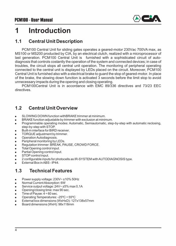
PCM100 Central Unit for sliding gates operates a geared-motor 230Vac 700VA max, as MS100 or MS200 producted by CIA, by an electrical clutch, realized with a microprocessor of last generation. PCM100 Central Unit is furnished with a sophisticated circuit of auto-diagnosis that controls costantly the operation of the system and connected devices; in case of troubles, the circuit stops all central unit operation. The monitoring of peripheral operating connected to the central unit is displayed by LEDs placed on the circuit. Moreover, PCM100 Central Unit is furnished also with a electrical brake to guard the stop of geared-motor. In place of the brake, the slowing down function is activated 3 seconds before the limit stop to avoid unnecessary impacts during the opening and closing operating.
PCM100Central Unit is in accordance with EMC 89/336 directives and 73/23 EEC directives.
SLOWING DOWN function withBRAKE trimmer at minimum.BRAKE function adjustable by trimmer with exclusion at minimum.Programmable operating modes: Automatic, Semiautomatic, step-by-step with automatic reclosing, step-by-step with STOP.Built-in interface for BIRD receiver.TORQUE adjustment by trimmer.Operation Autodiagnosis.Peripheral monitoring by LEDs.Regulation trimmer: BREAK, PAUSE, CROWD FORCE.Total Opening control input.Partial Opening control input.STOP control input.2 configurable inputs for photocells as IR-SYSTEM with AUTODIAGNOSIS type.
! External Box in ABS - IP44.
1.3 Technical Features
! Power supply voltage: 230V~ ±10% 50Hz! Normal Current Absorption: 6W ! Service output voltage: 24V~ ±5% max 0,1A! Opening/closing time: max 90 sec.! Time of Pause: 4 ÷ 60 sec.! Operating Temperatures: -25ºC ÷ 55ºC! External box dimensions (WxHxD): 127x138x57mm! Board dimensions (WxH): 98x118mm
Voltage fuse (250Vac 3,15A)
Trimmer A: electronic clutch
Trimmer B: time of pause
Trimmer C: electr. brake / slowing down
P1: total opening
P2: partial opening
LED Button P1
LED Button P2
LED photocell 1 status
LED photocell 2 status
LED opening limit stop status
LED closing limit stop status
LED STOP Status
LED microprocessor diagnosis
Setup Dip-Switch
Opening/closing limit stop connector, to use when central unit is installed inside motor.
230Vac power supply clamps
Flasher and motor clamps
BIRD and commands clamps
Photocells and 24 Vac clamps
Opening/closing limit stop clamps, to use when central unit is installed outside motor.
PCM100 - User Manual
2 Installation2.1 Board Description
17 18 19 20
1
42 3
14
15
6
5
7
8
10
11
9
12
13
21
16
7
2
3
8
9
6
1
4
5
10
11
12
13
14
15
16
17
18
19
20
21
autoapprendimentocodice radiocomando

4 5
Installation
1 Introduction
1.1 Central Unit Description
1.2 Central Unit Overview
!
!
!
!
!
!
!
!
!
!
!
!
PCM100 Central Unit for sliding gates operates a geared-motor 230Vac 700VA max, as MS100 or MS200 producted by CIA, by an electrical clutch, realized with a microprocessor of last generation. PCM100 Central Unit is furnished with a sophisticated circuit of auto-diagnosis that controls costantly the operation of the system and connected devices; in case of troubles, the circuit stops all central unit operation. The monitoring of peripheral operating connected to the central unit is displayed by LEDs placed on the circuit. Moreover, PCM100 Central Unit is furnished also with a electrical brake to guard the stop of geared-motor. In place of the brake, the slowing down function is activated 3 seconds before the limit stop to avoid unnecessary impacts during the opening and closing operating.
PCM100Central Unit is in accordance with EMC 89/336 directives and 73/23 EEC directives.
SLOWING DOWN function withBRAKE trimmer at minimum.BRAKE function adjustable by trimmer with exclusion at minimum.Programmable operating modes: Automatic, Semiautomatic, step-by-step with automatic reclosing, step-by-step with STOP.Built-in interface for BIRD receiver.TORQUE adjustment by trimmer.Operation Autodiagnosis.Peripheral monitoring by LEDs.Regulation trimmer: BREAK, PAUSE, CROWD FORCE.Total Opening control input.Partial Opening control input.STOP control input.2 configurable inputs for photocells as IR-SYSTEM with AUTODIAGNOSIS type.
! External Box in ABS - IP44.
1.3 Technical Features
! Power supply voltage: 230V~ ±10% 50Hz! Normal Current Absorption: 6W ! Service output voltage: 24V~ ±5% max 0,1A! Opening/closing time: max 90 sec.! Time of Pause: 4 ÷ 60 sec.! Operating Temperatures: -25ºC ÷ 55ºC! External box dimensions (WxHxD): 127x138x57mm! Board dimensions (WxH): 98x118mm
Voltage fuse (250Vac 3,15A)
Trimmer A: electronic clutch
Trimmer B: time of pause
Trimmer C: electr. brake / slowing down
P1: total opening
P2: partial opening
LED Button P1
LED Button P2
LED photocell 1 status
LED photocell 2 status
LED opening limit stop status
LED closing limit stop status
LED STOP Status
LED microprocessor diagnosis
Setup Dip-Switch
Opening/closing limit stop connector, to use when central unit is installed inside motor.
230Vac power supply clamps
Flasher and motor clamps
BIRD and commands clamps
Photocells and 24 Vac clamps
Opening/closing limit stop clamps, to use when central unit is installed outside motor.
PCM100 - User Manual
2 Installation2.1 Board Description
17 18 19 20
1
42 3
14
15
6
5
7
8
10
11
9
12
13
21
16
7
2
3
8
9
6
1
4
5
10
11
12
13
14
15
16
17
18
19
20
21
autoapprendimentocodice radiocomando
6
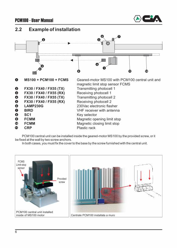
2.2 Example of installation
MS100 + PCM100 + FCMS Geared-motor MS100 with PCM100 central unit and magnetic limit stop sensor FCMS
FX30 / FX40 / FX55 (TX) Transmitting photocell 1FX30 / FX40 / FX55 (RX) Receiving photocell 1FX30 / FX40 / FX55 (TX) Transmitting photocell 2FX30 / FX40 / FX55 (RX) Receiving photocell 2LAMP230G 230Vac electronic flasherBIRD VHF receiver with antennaSC1 Key selectorFCMM Magnetic opening limit stopFCMM Magnetic closing limit stopCRP Plastic rack
PCM100 central unit can be installed inside the geared-motor MS100 by the provided screw, or it be fixed at the wall by two screw anchors.
In both cases, you must fix the cover to the base by the screw furnished with the central unit.
7
2
3
8
6
1
4
5
1
2 3
7
8
45
6
PCM100 - User Manual
9 10
9
10
11
11
2.3 Connections
7
Installation
Providedscrew
PCM100 central unit installedinside of MS100 motor Centrale PCM100 installata a muro
FCMSLimit-stop
sensor
1 2 3 4 5 6 7 8 9 10 11 12 13 14 15 16 17 18 19
20
21
22
NOTE: If it should be necessary to invert the limit-stop wires, invert the
and magnets at page 6.9 10
Use this connector only if central unit board is installed inside of the geared-motor.
Limit-stopconnector
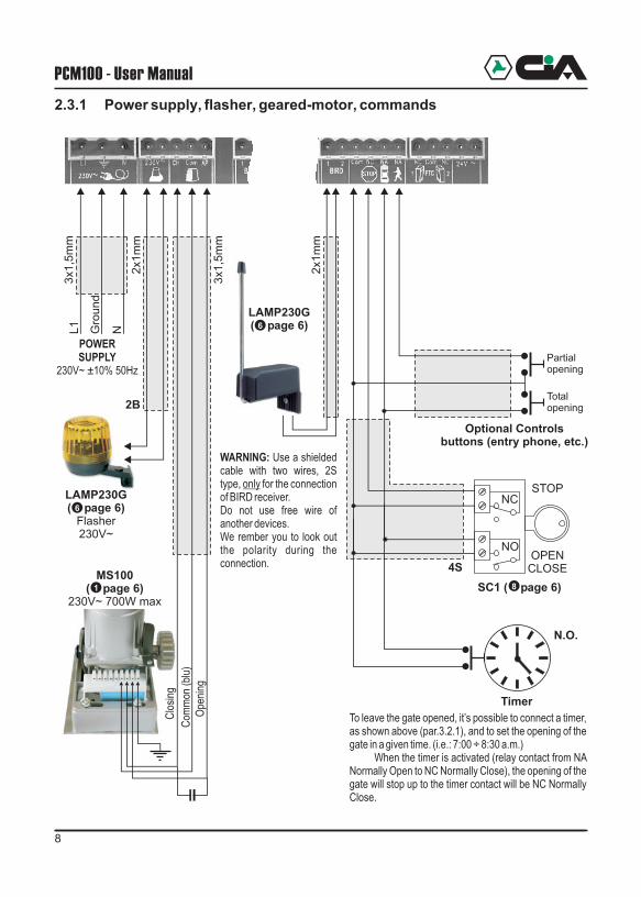
11 - Common12 - Pulse STOP (NC)13 - Pulse A (NO)14 - Pulse B (NO)
COMMANDS
15 - NC16 - Common17 - NC18 - 24V~ max 100mA19 - 24V~ max 100mA
1 - L12 - Ground3 - N
POWER SUPPLY 230V~ ±10% 50Hz
6 - Closing7 - Common (blu wire)8 - Opening
GEARED MOTOR230V~ 700W max
4 - Pole 15 - Pole 2
ELECTRONIC FLASHER 230V~
PHOTOCELLS(FX30 - FX40 - FX55)
9 - Pole 1 (clamp 1 BIRD)10 - Pole 2 (clamp 2 BIRD)
BIRD ANTENNA
20 - Opening limit-stop21 - Limit-stop common22 - Closing limit-stop
LIMIT-STOP
Use this clamps only if central unit board is installed outside of the geared-motor.

6
2.2 Example of installation
MS100 + PCM100 + FCMS Geared-motor MS100 with PCM100 central unit and magnetic limit stop sensor FCMS
FX30 / FX40 / FX55 (TX) Transmitting photocell 1FX30 / FX40 / FX55 (RX) Receiving photocell 1FX30 / FX40 / FX55 (TX) Transmitting photocell 2FX30 / FX40 / FX55 (RX) Receiving photocell 2LAMP230G 230Vac electronic flasherBIRD VHF receiver with antennaSC1 Key selectorFCMM Magnetic opening limit stopFCMM Magnetic closing limit stopCRP Plastic rack
PCM100 central unit can be installed inside the geared-motor MS100 by the provided screw, or it be fixed at the wall by two screw anchors.
In both cases, you must fix the cover to the base by the screw furnished with the central unit.
7
2
3
8
6
1
4
5
1
2 3
7
8
45
6
PCM100 - User Manual
9 10
9
10
11
11
2.3 Connections
7
Installation
Providedscrew
PCM100 central unit installedinside of MS100 motor Centrale PCM100 installata a muro
FCMSLimit-stop
sensor
1 2 3 4 5 6 7 8 9 10 11 12 13 14 15 16 17 18 19
20
21
22
NOTE: If it should be necessary to invert the limit-stop wires, invert the
and magnets at page 6.9 10
Use this connector only if central unit board is installed inside of the geared-motor.
Limit-stopconnector
11 - Common12 - Pulse STOP (NC)13 - Pulse A (NO)14 - Pulse B (NO)
COMMANDS
15 - NC16 - Common17 - NC18 - 24V~ max 100mA19 - 24V~ max 100mA
1 - L12 - Ground3 - N
POWER SUPPLY 230V~ ±10% 50Hz
6 - Closing7 - Common (blu wire)8 - Opening
GEARED MOTOR230V~ 700W max
4 - Pole 15 - Pole 2
ELECTRONIC FLASHER 230V~
PHOTOCELLS(FX30 - FX40 - FX55)
9 - Pole 1 (clamp 1 BIRD)10 - Pole 2 (clamp 2 BIRD)
BIRD ANTENNA
20 - Opening limit-stop21 - Limit-stop common22 - Closing limit-stop
LIMIT-STOP
Use this clamps only if central unit board is installed outside of the geared-motor.
STOP
OPENCLOSE
Partialopening
Totalopening
Optional Controls buttons (entry phone, etc.)
NC
NO
SC1 ( page 6)8
4S
2.3.2 Relay photocells (FX40, FX55)
8 9
Installation
2.3.1 Power supply, flasher, geared-motor, commands
PCM100 - User Manual
NC
NC
24V~ 24V~
24V~ 24V~
2
5
RX( page 6)
3
Photocell 2
Photocell 1
2B2 2B
Photocell 2
+-
+-
+-
+-Photocell 1
2.3.3 Photocells with autodiagnosis (FX30)
2B2B
2B
TX( page 6)
TX( page 6)
RX( page 6)
4
RX( page 6) 4 5
TX( page 6)2
TX( page 6)
RX( page 6)3
2BTimer
N.O.
3x1
,5m
m
POWERSUPPLY
230V~ ±10% 50Hz
L1
Gro
un
d
N
LAMP230G( page 6)
Flasher230V~
2B
6
Ope
ning
Com
mon
(bl
u)
Clo
sing
MS100( page 6)
230V~ 700W max1
3x1
,5m
m
2x1
mm
To leave the gate opened, it’s possible to connect a timer, as shown above (par.3.2.1), and to set the opening of the gate in a given time. (i.e.: 7:00 ÷ 8:30 a.m.)
When the timer is activated (relay contact from NA Normally Open to NC Normally Close), the opening of the gate will stop up to the timer contact will be NC Normally Close.
2x1
mm
WARNING: Use a shielded cable with two wires, 2S type, only for the connection of BIRD receiver.Do not use free wire of another devices.We rember you to look out the polarity during the connection.
LAMP230G( page 6)6
ONDIP1
SW4=ON
ONDIP1
SW4=OFF

10 11
SetupPCM100 - User Manual
3 Setup
3.1 Operating mode
The operating mode and the various options are settable by the switches 1, 2 and 3 of the dip-switch present on the board ( a page 5). The switch 4 can set the installed photocell model (see previous page). Here's a summary of all options:
To learn about operating logics see next paragraph.
ATTENTION: The DIP- SWITCH setting up has to be made with central unit switched off.
15
Automatic for Parkoperating
OFF OFF
Automatic operating ON OFF
Step by step with automatic closing
OFF ON
Step by stepwith STOP
ON ON
Locking enabled
Locking disabled
Switch 1 and 2:Operating
Switch 3:Opening locking
on photocells
interruption
SWITCH 4:Tipo di
fotocellula installata
ON
ON
ON
ON
ON
OFF
ON
ON
ON
OFF
ON
ON
FX30 (autodiagnosis)
FX40 - FX55
OPEN IN PAUSE
CLOSING
The reclosing is stopped and at the end of the pause, it restores other 5 sec. up to the reset
The gate stops and it opens immediately. Stops operation and the gate opens immediately
IN STOPRestarts the operating procedure before the
STOP (closing or opening)The pulses A and B will be ignored.
The opening or closing operation are locked
GATESTATUS
PULSE A PULSE B STOP PHOTOCELL 1 PHOTOCELL 2
CLOSE
OPENING
PARTIALOPEN
IN PAUSE
CLOSING
3.1.1 AUTOMATIC FOR PARKS (SW1=OFF - SW2=OFF)
One pulse allows : opening , pause , automatic closing .During the opening operation, other pulses will be ignored. During the closing operation,
possible pulses stop and reverse the movement of gate immediately.A contact closed on PULSE A ( Clock function ) allows to open the gate up to the setted pause
and it be open up to the opening of the contact.
3.1.2 AUTOMATIC operating ( SW1=ON - SW2=OFF)
One pulse allows :opening, pause, automatic closing.During opening and closing procedures, every pulse stops and reverse the movement of the
gate immediately.During the pause, a pulse recloses the gate immediately.
operating
Total Opening and reclosing after the time
of pause
No effect if the opening is started by the
PULSE A
No Effect
Stops operation and switches to
STOP mode
No Effect
The reclosing is stopped and at the end of the pause, it restores other 5 sec. up to the reset
The reclosing is stopped and at the end of the pause, it restores other 5 sec. up to the reset
A total opening is possible.
The closing is stopped and the gate opens again immediately
Stops operation and the gate opens immediately
Restarts the operating procedure before the STOP (closing or opening)
The pulses A and B will be ignored.The opening or closing operation are locked
Partial Opening and closing operation after
the time of pause
Total Opening if the opening is started by
the PULSE B
GATESTATUS
PULSE A PULSE B STOP
CLOSE
OPENING
Total Opening and reclosing after the time
of pauseSee SWITCH 3 pages 9 and 10
Stops operation and switches to
STOP mode
No effect
Partial Opening and reclosing after the time
of pause
The gate stops and it recloses immediately.
The gate recloses immediately
PHOTOCELL 1 PHOTOCELL 2
TOTALOPEN
IN PAUSE
Total Opening
The reclosing is stopped and at the end of the
pause it restores other 5 sec. up to the reset
The reclosing is stopped and at the end of the pause, it restores other 5 sec. up to the reset
Disables A and B pulses and disable opening
Disables A and B pulses and disable opening
ON
ON
See SWITCH 3 pages 9 and 10
IN STOP
12 13
PCM100 - User Manual
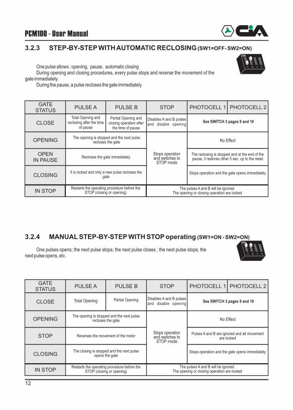
3.2.3 STEP-BY-STEP WITH AUTOMATIC RECLOSING (SW1=OFF- SW2=ON)
One pulse allows : opening, pause, automatic closingDuring opening and closing procedures, every pulse stops and reverse the movement of the
gate immediately.During the pause, a pulse recloses the gate immediately.
3.2.4 MANUAL STEP-BY-STEP WITH STOP operating (SW1=ON - SW2=ON)
One pulses opens; the next pulse stops; the next pulse closes ; the next pulse stops; the next pulse opens, etc .
OPEN IN PAUSE
CLOSING
The reclosing is stopped and at the end of the pause, it restores other 5 sec. up to the reset
Stops operation and the gate opens immediately
IN STOPRestarts the operating procedure before the
STOP (closing or opening)The pulses A and B will be ignored.
The opening or closing operation are locked
GATESTATUS
PULSE A PULSE B STOP
CLOSE
OPENING
Total Opening and reclosing after the time
of pause
Stops operation and switches to
STOP mode
No Effect
Partial Opening and closing operation after
the time of pause
The opening is stopped and the next pulse recloses the gate
Recloses the gate immediately
It is locked and only a new pulse recloses the gate
STOP
CLOSING
Pulses A and B are ignored and all movement are locked
Stops operation and the gate opens immediately
IN STOPRestarts the operating procedure before the
STOP (closing or opening)The pulses A and B will be ignored.
The opening or closing operation are locked
GATESTATUS
PULSE A PULSE B STOP
CLOSE
OPENING
Total Opening
Stops operation and switches to
STOP mode
No Effect
Partial Opening
The opening is stopped and the next pulse recloses the gate
Reverses the movement of the motor
The closing is stopped and the next pulse opens the gate
PHOTOCELL 1 PHOTOCELL 2
PHOTOCELL 1 PHOTOCELL 2
Disables A and B pulses and disable opening
Disables A and B pulses and disable opening
3.2 Electronic clutch adjustment (trimmer A)
This adjustment works on the thrust force of geared-motor: this force must cause the moving of the gate, and it’s closely dependent on the weight of its structure.
During the movement, also the gate acquires a thrust force.Under provisions of the law, the adjustment must be made so that the thrust force of the
gate is equal to 15Kg; it means that a force equal to 15Kg, in opposition to the movement of the gate, must stop the gate during its movement.
To set this adjustment, we suggest you to use an instrument called linear dynamometer.
3.3 Time of pause adjustment (trimmer B)
If the central unit is setted on Automatic operating or Automatic operating for Parks, you must adjust the time of pause that must elapse between the end of the opening and the start of the closing of the gate.
3.4 Electronic Brake / Slowing Down (trimmer C)
3.5 Control LEDs
Here's a summary of the signallings LEDs present on the board:
Turned in anticlockwise direction:Electronic brake: disabledSlowing down: enabled at the end of opening / closing
Turned in clockwise direction:Electronic brake: enabled, reduces the movement after the limit/stop is
activated.Slowing down: disabled
OFF
Photocell 1 engaged
STOP command active
Pulse on input A(total opening)
Pulse on input B(partial opening)
st/bygreen
yellow
red
red Photocell 2 engaged
st/by
red
red
Opening limit-stopengaged
Closing limit-stop engaged
green Normal operating Anomaly
green
LED BLINKINGON
Anomaly
COLOR
st/by
/
/
/
/
st/by
st/by
st/by
st/by
/
/
/
12
9
7
10
8
13
11
14
DIP1
ON
ON
Setup
See SWITCH 3 pages 9 and 10
See SWITCH 3 pages 9 and 10

12 13
PCM100 - User Manual
3.2.3 STEP-BY-STEP WITH AUTOMATIC RECLOSING (SW1=OFF- SW2=ON)
One pulse allows : opening, pause, automatic closingDuring opening and closing procedures, every pulse stops and reverse the movement of the
gate immediately.During the pause, a pulse recloses the gate immediately.
3.2.4 MANUAL STEP-BY-STEP WITH STOP operating (SW1=ON - SW2=ON)
One pulses opens; the next pulse stops; the next pulse closes ; the next pulse stops; the next pulse opens, etc .
OPEN IN PAUSE
CLOSING
The reclosing is stopped and at the end of the pause, it restores other 5 sec. up to the reset
Stops operation and the gate opens immediately
IN STOPRestarts the operating procedure before the
STOP (closing or opening)The pulses A and B will be ignored.
The opening or closing operation are locked
GATESTATUS
PULSE A PULSE B STOP
CLOSE
OPENING
Total Opening and reclosing after the time
of pause
Stops operation and switches to
STOP mode
No Effect
Partial Opening and closing operation after
the time of pause
The opening is stopped and the next pulse recloses the gate
Recloses the gate immediately
It is locked and only a new pulse recloses the gate
STOP
CLOSING
Pulses A and B are ignored and all movement are locked
Stops operation and the gate opens immediately
IN STOPRestarts the operating procedure before the
STOP (closing or opening)The pulses A and B will be ignored.
The opening or closing operation are locked
GATESTATUS
PULSE A PULSE B STOP
CLOSE
OPENING
Total Opening
Stops operation and switches to
STOP mode
No Effect
Partial Opening
The opening is stopped and the next pulse recloses the gate
Reverses the movement of the motor
The closing is stopped and the next pulse opens the gate
PHOTOCELL 1 PHOTOCELL 2
PHOTOCELL 1 PHOTOCELL 2
Disables A and B pulses and disable opening
Disables A and B pulses and disable opening
3.2 Electronic clutch adjustment (trimmer A)
This adjustment works on the thrust force of geared-motor: this force must cause the moving of the gate, and it’s closely dependent on the weight of its structure.
During the movement, also the gate acquires a thrust force.Under provisions of the law, the adjustment must be made so that the thrust force of the
gate is equal to 15Kg; it means that a force equal to 15Kg, in opposition to the movement of the gate, must stop the gate during its movement.
To set this adjustment, we suggest you to use an instrument called linear dynamometer.
3.3 Time of pause adjustment (trimmer B)
If the central unit is setted on Automatic operating or Automatic operating for Parks, you must adjust the time of pause that must elapse between the end of the opening and the start of the closing of the gate.
3.4 Electronic Brake / Slowing Down (trimmer C)
3.5 Control LEDs
Here's a summary of the signallings LEDs present on the board:
Turned in anticlockwise direction:Electronic brake: disabledSlowing down: enabled at the end of opening / closing
Turned in clockwise direction:Electronic brake: enabled, reduces the movement after the limit/stop is
activated.Slowing down: disabled
OFF
Photocell 1 engaged
STOP command active
Pulse on input A(total opening)
Pulse on input B(partial opening)
st/bygreen
yellow
red
red Photocell 2 engaged
st/by
red
red
Opening limit-stopengaged
Closing limit-stop engaged
green Normal operating Anomaly
green
LED BLINKINGON
Anomaly
COLOR
st/by
/
/
/
/
st/by
st/by
st/by
st/by
/
/
/
12
9
7
10
8
13
11
14
DIP1
ON
ON
Setup
See SWITCH 3 pages 9 and 10
See SWITCH 3 pages 9 and 10

14
PCM100 - User Manual
15
Setup
2.6 Remote-control receiver setup
Visualization of the programmed code
! Keep pressed P1 and P2 buttons ( and at page 5) for at least 2 seconds and not more than 5 seconds, up to the two LEDs ( and at page 5) light on.
! Pressing the P1 button it will be displayed the 12-bit code of "A" channel by a sequence of blinkings of the LEDs:! one blink of LED indicates dip switch ON! one blink of LED indicates dip switch OFF
! At the end of the sequence, it will exit automatically the setup mode.
NOTE: If no buttons is pressed in 5 seconds, the produre is stopped and no code will be displayed.
NOTE: To visualize the code of the “B” channel, repeat the same procedure using the P2 button.
Auto-learning of the remote-control code
! Keep pressed P1 and P2 buttons ( and at page 5) for at least 5 seconds up to the two LEDs start to blink ( and at page 5).
! Press P1 button, only LED starts to blink.! During the blinking, within 5 seconds press the "A" button of the remote-control to let
acquire the code.! The LED starts a sequence of blinkings to indicate that the code has been acquired and
it will exit automatically the setup mode.
NOTE: If no remote-control is activated in 10 seconds, the setup is stopped and no code will be programmed.
NOTE: For the acquisition of the code of the channel "B” of the remote-control, repeat the procedure using P2 buttons and LED .
Summary of setup accessing times
5 6
7 8
7
8
5 6
7 8
7
7
8
0 sec. 2 sec. 5 sec.
LED “1” and “2”light
LED “1” and “2”blink
Time of simultaneous pressure of P1 e P2 buttons:
LED “1” and “2”turn off
Release P1 and P2 buttons to enter in Code
Display Mode.
Release P1 and P2 buttons to enter in
Auto-acquisition Code Mode
LED Status
Function No action
2.7 Remote-control setup
The TWIN allows the independent set-up for each of 2 channels; memorize a different code on each button, and a channel to select (A, B, C, or D) also if they are not on the same code. The set-up operation has to be repeated for each of the 2 buttons of the radio-control.
In order to start the set-up phase you have to push both the buttons for some seconds
+ For insert a new code you have to access with the following sequence: "1" - "1" - "0" - "0”
& During the insert of each code the LED will switch off for some seconds.! Insert the
quadri-channelsquadri-channels
! The LED switch off at the end of the set-up.
* For example, to duplicate the left button (channel A) of a previous TWIN version that has the dip-switch set as following:
You have to digit the following buttons sequence:
1 1 0 0 1 0 0 1 1 0 1 0 0 1 1 0 (fast flash of the LED) 1Access code channel A assigned to left button
+ For read the code you have to digit the following sequence:"1" - "0" - "1" -"0"! Push on the button that you want to know the code! The LED switch off and it start one series of 12 flashes:
? A brief flash means ? A long flash means
During the set-up, if you don’t push on any button for at least 5 seconds the LED switch off and the setting phase finish automatically.
It’s possible to
, until the LED remains on, then you have to leave them:
! Insert the 10 digit of the code using:
? “0” (right button ): It means dip-switch "OFF" for the previous TWIN versions*? “1” (left button): It means dip-switch "ON" for the previous TWIN versions*
2 digit of the channel using:
? Channel A "1" - "0": It means the left button for the previous TWIN versions? Channel B "1" - "1": It means the right button for the previous TWIN versions? Channel C "0" - "0": to use together with receivers ? Channel D "0" - "1": to use together with receivers
! Push the button that you want to assign at the code.
"0""1”
Unscrew the screw on the bottom of the radio-control to open the plastic cover, take off the old battery and insert a new one according with the polarities indicated on the plastic cover.
Check the correct operation of the two buttons after to close the plastic cover.
ON
OFF
1 2 3 4 5 6 7 8 9 10

4 Maintenance
F1 3,15A 250V VOLTAGE Fuse This fuse allows the protection from overloads of the central unit transformer, from voltage drops of the flasher and of the geared-motor.
4.1 Gate
It`s suggested to carry out periodic checks on the structure of the gate and in particular it`s suggested to verify verificare the perfect condition of gears, ruck and all mechanical elements.
4.2 Fuses
16 425ADE-3.00
PCM100 - User Manual


![· RAPPORTO DI AUDIT kiwa Partner for progress ... OSGSSL ( BS OHSAS 18001; a SGE (a ISO 50001; a C] SGSA( ISO 22000; a Integrato Organizzazione valutata](https://img.pdfslide.us/doc/110x75/5b5808357f8b9a6a5d8b79aa/-rapporto-di-audit-kiwa-partner-for-progress-osgssl-bs-ohsas-18001-a-sge.jpg)