Embed Size (px)
Citation preview

NEW-222-1 (09/2017)PAGE 1 OF 15
PCD & CBN Tangential MillingTEDIFEED is the newest line of mill with tangential inserts available with PCD and CBN inserts, single, double and full cutting edges. TEDIFEED is designed for machining operations from heavy roughing to superfinishing. Availa-ble with all holders, with cylindrical shank, monoblock or shell type config-urations. A wide range of diameters, lengths and number of cutting edges guarantee the best results in every applications.
Features:• Suitable for high feed machining • Low cutting forces• Insert available with single tip, double tip and full edge• High number of cutting edges for high productivity
DiametersMetric: 25.0 mm – 250 mmInch: 1.0” – 10.0”
BodiesCylindricalShell TypeIntegral on request
UPDATED
845 South Lyford Road, Rockford, IL 61108Tel: 815.387.6600, Fax: 815.387.6968
NEW-222-1 (09/2017)PAGE 2 OF 15
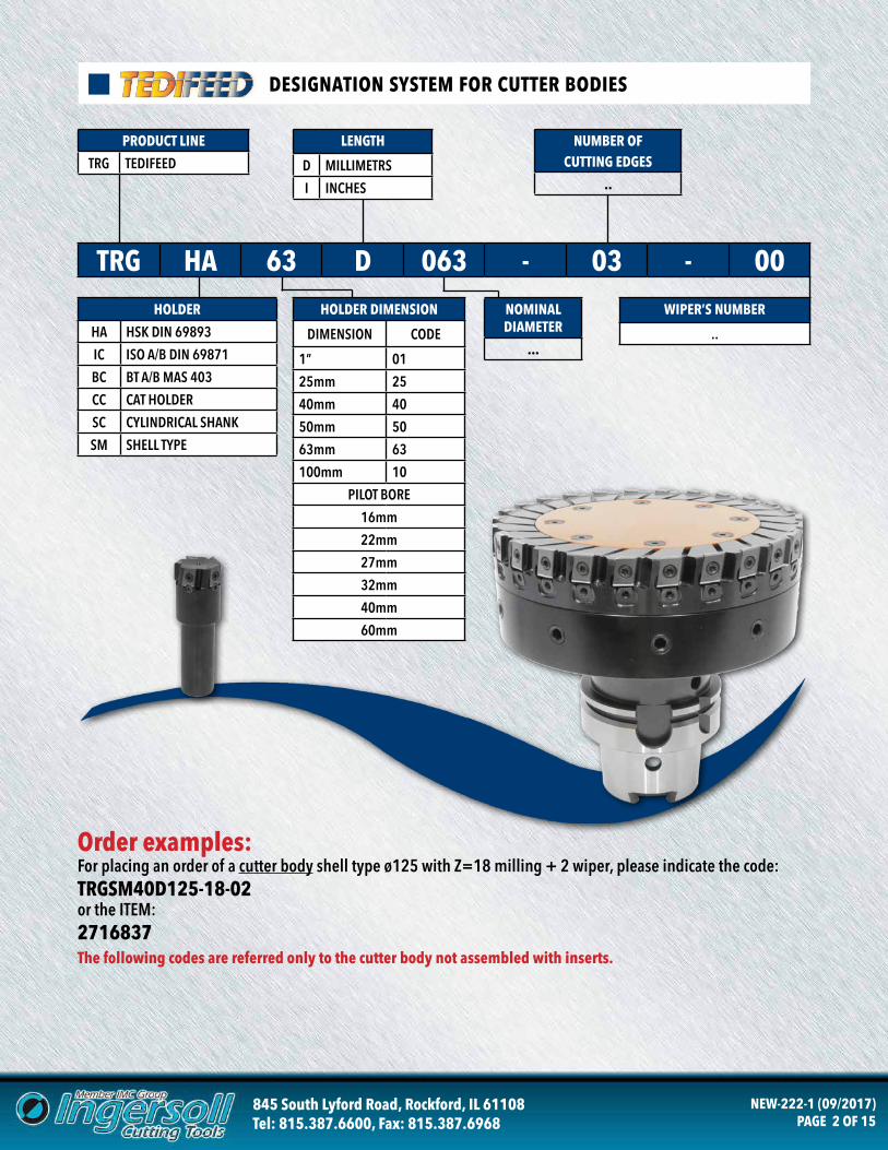
DESIGNATION SYSTEM FOR CUTTER BODIES
PRODUCT LINE
TRG TEDIFEED
LENGTH
D MILLIMETRS
I INCHES
NUMBER OF CUTTING EDGES
..
HOLDER
HA HSK DIN 69893
IC ISO A/B DIN 69871
BC BT A/B MAS 403
CC CAT HOLDER
SC CYLINDRICAL SHANK
SM SHELL TYPE
HOLDER DIMENSION
DIMENSION CODE
1” 01
25mm 25
40mm 40
50mm 50
63mm 63
100mm 10
PILOT BORE
16mm
22mm
27mm
32mm
40mm
60mm
TRG HA 63 D 063 - 03 - 00NOMINAL DIAMETER
...
WIPER’S NUMBER
..
Order examples:For placing an order of a cutter body shell type ø125 with Z=18 milling + 2 wiper, please indicate the code:TRGSM40D125-18-02or the ITEM:2716837The following codes are referred only to the cutter body not assembled with inserts.
845 South Lyford Road, Rockford, IL 61108Tel: 815.387.6600, Fax: 815.387.6968
NEW-222-1 (09/2017)PAGE 3 OF 15
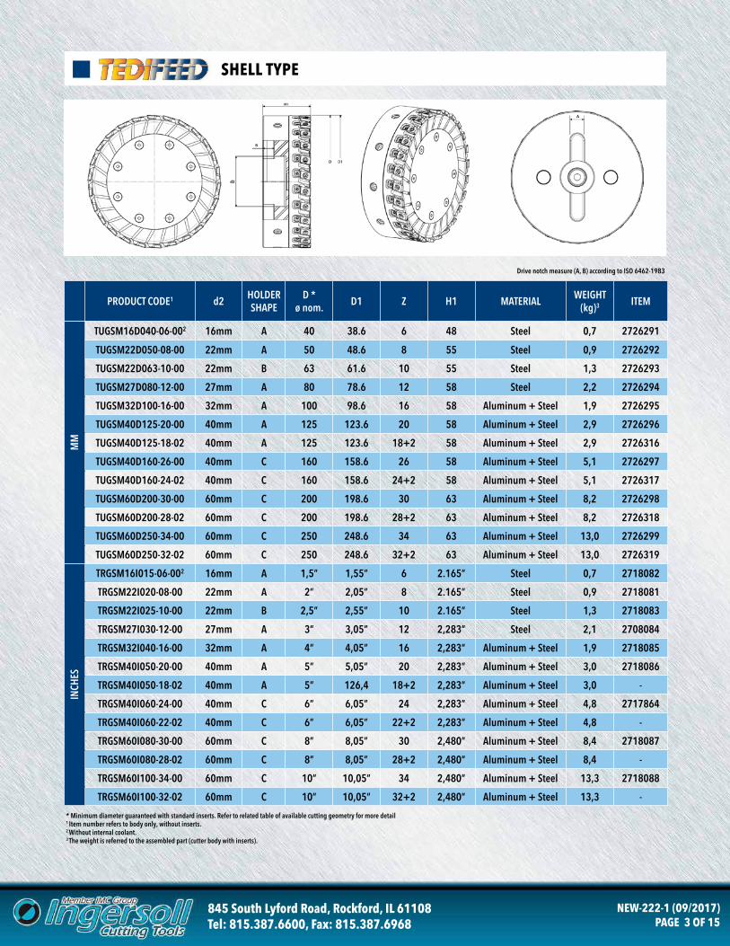
SHELL TYPE
* Minimum diameter guaranteed with standard inserts. Refer to related table of available cutting geometry for more detail1 Item number refers to body only, without inserts.2 Without internal coolant.3 The weight is referred to the assembled part (cutter body with inserts).
Drive notch measure (A, B) according to ISO 6462-1983
PRODUCT CODE1 d2 HOLDER SHAPE
D *ø nom. D1 Z H1 MATERIAL WEIGHT
(kg)3 ITEM
TUGSM16D040-06-002 16mm A 40 38.6 6 48 Steel 0,7 2726291
TUGSM22D050-08-00 22mm A 50 48.6 8 55 Steel 0,9 2726292
TUGSM22D063-10-00 22mm B 63 61.6 10 55 Steel 1,3 2726293
TUGSM27D080-12-00 27mm A 80 78.6 12 58 Steel 2,2 2726294
TUGSM32D100-16-00 32mm A 100 98.6 16 58 Aluminum + Steel 1,9 2726295
TUGSM40D125-20-00 40mm A 125 123.6 20 58 Aluminum + Steel 2,9 2726296
TUGSM40D125-18-02 40mm A 125 123.6 18+2 58 Aluminum + Steel 2,9 2726316
TUGSM40D160-26-00 40mm C 160 158.6 26 58 Aluminum + Steel 5,1 2726297
TUGSM40D160-24-02 40mm C 160 158.6 24+2 58 Aluminum + Steel 5,1 2726317
TUGSM60D200-30-00 60mm C 200 198.6 30 63 Aluminum + Steel 8,2 2726298
TUGSM60D200-28-02 60mm C 200 198.6 28+2 63 Aluminum + Steel 8,2 2726318
TUGSM60D250-34-00 60mm C 250 248.6 34 63 Aluminum + Steel 13,0 2726299
TUGSM60D250-32-02 60mm C 250 248.6 32+2 63 Aluminum + Steel 13,0 2726319
TRGSM16I015-06-002 16mm A 1,5” 1,55” 6 2.165” Steel 0,7 2718082
TRGSM22I020-08-00 22mm A 2” 2,05” 8 2.165” Steel 0,9 2718081
TRGSM22I025-10-00 22mm B 2,5” 2,55” 10 2.165” Steel 1,3 2718083
TRGSM27I030-12-00 27mm A 3” 3,05” 12 2,283” Steel 2,1 2708084
TRGSM32I040-16-00 32mm A 4” 4,05” 16 2,283” Aluminum + Steel 1,9 2718085
TRGSM40I050-20-00 40mm A 5” 5,05” 20 2,283” Aluminum + Steel 3,0 2718086
TRGSM40I050-18-02 40mm A 5” 126,4 18+2 2,283” Aluminum + Steel 3,0 -
TRGSM40I060-24-00 40mm C 6” 6,05” 24 2,283” Aluminum + Steel 4,8 2717864
TRGSM40I060-22-02 40mm C 6” 6,05” 22+2 2,283” Aluminum + Steel 4,8 -
TRGSM60I080-30-00 60mm C 8” 8,05” 30 2,480” Aluminum + Steel 8,4 2718087
TRGSM60I080-28-02 60mm C 8” 8,05” 28+2 2,480” Aluminum + Steel 8,4 -
TRGSM60I100-34-00 60mm C 10” 10,05” 34 2,480” Aluminum + Steel 13,3 2718088
TRGSM60I100-32-02 60mm C 10” 10,05” 32+2 2,480” Aluminum + Steel 13,3 -
MM
INCH
ES
845 South Lyford Road, Rockford, IL 61108Tel: 815.387.6600, Fax: 815.387.6968
NEW-222-1 (09/2017)PAGE 4 OF 15
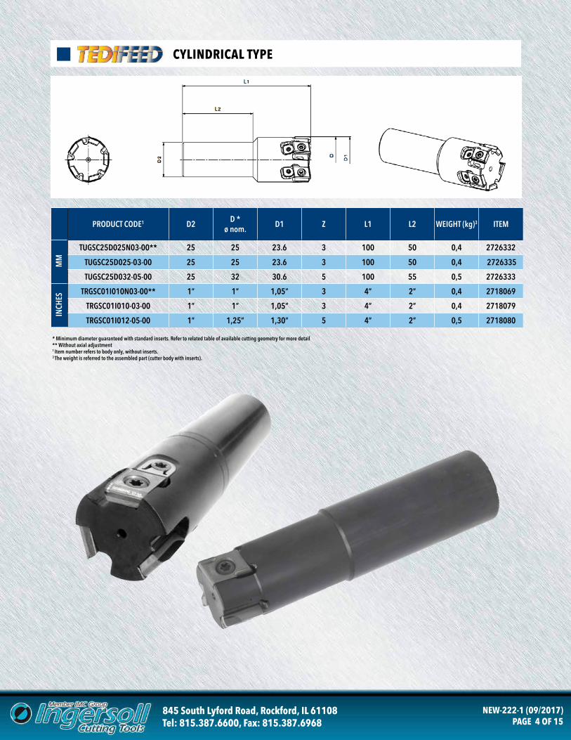
CYLINDRICAL TYPE
* Minimum diameter guaranteed with standard inserts. Refer to related table of available cutting geometry for more detail** Without axial adjustment1 Item number refers to body only, without inserts.3 The weight is referred to the assembled part (cutter body with inserts).
PRODUCT CODE1 D2 D *ø nom. D1 Z L1 L2 WEIGHT (kg)3 ITEM
TUGSC25D025N03-00** 25 25 23.6 3 100 50 0,4 2726332
TUGSC25D025-03-00 25 25 23.6 3 100 50 0,4 2726335
TUGSC25D032-05-00 25 32 30.6 5 100 55 0,5 2726333
TRGSC01I010N03-00** 1” 1” 1,05” 3 4” 2” 0,4 2718069
TRGSC01I010-03-00 1” 1” 1,05” 3 4” 2” 0,4 2718079
TRGSC01I012-05-00 1” 1,25” 1,30” 5 4” 2” 0,5 2718080
MM
INCH
ES
845 South Lyford Road, Rockford, IL 61108Tel: 815.387.6600, Fax: 815.387.6968
NEW-222-1 (09/2017)PAGE 5 OF 15
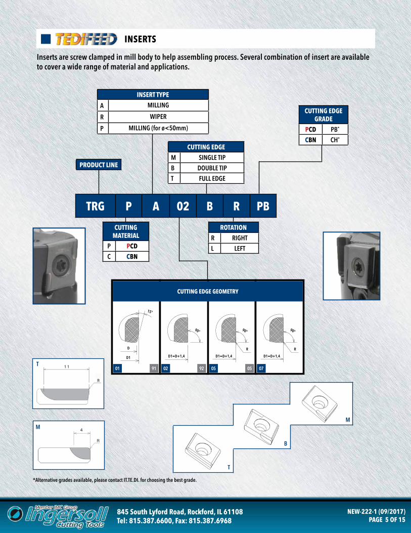
INSERTS
Inserts are screw clamped in mill body to help assembling process. Several combination of insert are available to cover a wide range of material and applications.
TRG P A 02 B R PB
CUTTINGMATERIAL
P PCD
C CBN
CUTTING EDGE GRADE
PCD PB*
CBN CH*
PRODUCT LINE
CUTTING EDGE
M SINGLE TIP
B DOUBLE TIP
T FULL EDGE
ROTATION
R RIGHT
L LEFT
01 0502 07
D
D1=D+1,4 D1=D+1,4 D1=D+1,4
R R
D1
15°
90° 90° 90°
CUTTING EDGE GEOMETRY
9291 05
INSERT TYPE
A MILLING
R WIPER
P MILLING (for ø<50mm)
T
M
*Alternative grades available, please contact IT.TE.DI. for choosing the best grade.
T
B
M
845 South Lyford Road, Rockford, IL 61108Tel: 815.387.6600, Fax: 815.387.6968
NEW-222-1 (09/2017)PAGE 6 OF 15
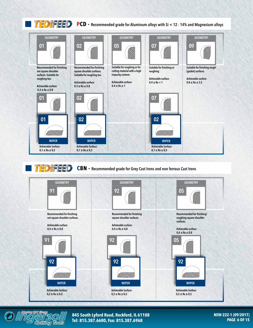
PCD - Recommended grade for Aluminum alloys with Si < 12 - 14% and Magnesium alloys
CBN - Recommended grade for Grey Cast Irons and non ferrous Cast Irons
GEOMETRY GEOMETRY
91 92 05
GEOMETRY
Recommended for finishing not square shoulder surfaces.
Achievable surface: 0,4 ≤ Ra ≤ 0,8
Recommended for finishing square shoulder surfaces.
Achievable surface: 0,4 ≤ Ra ≤ 0,8
Recommended for finishing/roughing square shoulder surfaces.
Achievable surface: 0,4 ≤ Ra ≤ 0,8
91 92 05
WIPER WIPER WIPER
92 92 92
Achievable Surface:0,2 ≤ Ra ≤ 0,5
Achievable Surface:0,2 ≤ Ra ≤ 0,5
Achievable Surface:0,2 ≤ Ra ≤ 0,5
Recommended for finishing not square shoulder surfaces. Suitable for roughing too.
Achievable surface: 0.3 ≤ Ra ≤ 0.8
Recommended for finishing square shoulder surfaces. Suitable for roughing too.
Achievable surface: 0.3 ≤ Ra ≤ 0.8
Suitable for finishing or roughing
Achievable surface: 0.4 ≤ Ra < 1
Suitable for finishing rough (gasket) surfaces
Achievable surface: 0.8 ≤ Ra ≤ 3.2
01 02 07 09
GEOMETRY GEOMETRY GEOMETRY GEOMETRY
Achievable Surface:0,1 ≤ Ra ≤ 0,5
01
WIPER
01
02
WIPER
Achievable Surface:0,1 ≤ Ra ≤ 0,5
02
07
WIPER
Achievable Surface:0,1 ≤ Ra ≤ 0,5
02
Suitable for roughing or for cutting material with a high impurity content.
Achievable surface: 0.4 ≤ Ra ≤ 1
05
GEOMETRY
845 South Lyford Road, Rockford, IL 61108Tel: 815.387.6600, Fax: 815.387.6968
NEW-222-1 (09/2017)PAGE 7 OF 15
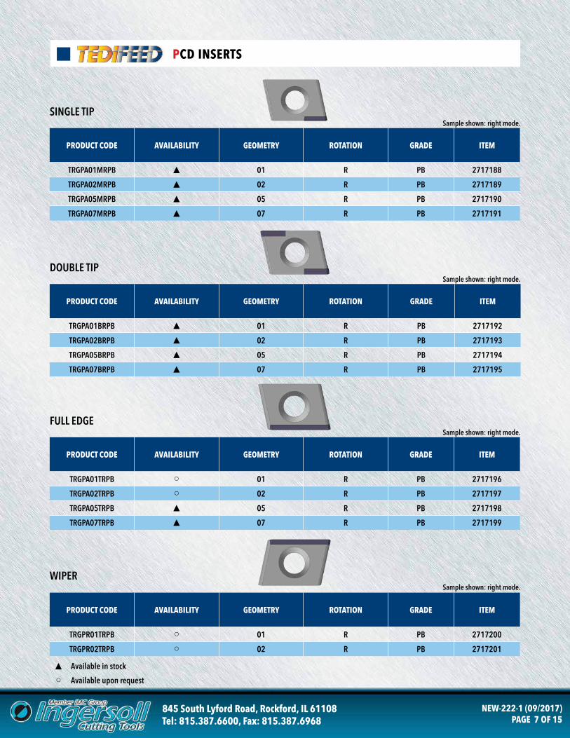
PCD INSERTS
PRODUCT CODE AVAILABILITY GEOMETRY ROTATION GRADE ITEM
TRGPA01MRPB ▲ 01 R PB 2717188
TRGPA02MRPB ▲ 02 R PB 2717189
TRGPA05MRPB ▲ 05 R PB 2717190
TRGPA07MRPB ▲ 07 R PB 2717191
PRODUCT CODE AVAILABILITY GEOMETRY ROTATION GRADE ITEM
TRGPA01BRPB ▲ 01 R PB 2717192
TRGPA02BRPB ▲ 02 R PB 2717193
TRGPA05BRPB ▲ 05 R PB 2717194
TRGPA07BRPB ▲ 07 R PB 2717195
SINGLE TIP
DOUBLE TIP
Sample shown: right mode.
Sample shown: right mode.
PRODUCT CODE AVAILABILITY GEOMETRY ROTATION GRADE ITEM
TRGPA01TRPB ○ 01 R PB 2717196
TRGPA02TRPB ○ 02 R PB 2717197
TRGPA05TRPB ▲ 05 R PB 2717198
TRGPA07TRPB ▲ 07 R PB 2717199
FULL EDGESample shown: right mode.
PRODUCT CODE AVAILABILITY GEOMETRY ROTATION GRADE ITEM
TRGPR01TRPB ○ 01 R PB 2717200
TRGPR02TRPB ○ 02 R PB 2717201
WIPERSample shown: right mode.
▲ Available in stock
○ Available upon request
845 South Lyford Road, Rockford, IL 61108Tel: 815.387.6600, Fax: 815.387.6968
NEW-222-1 (09/2017)PAGE 8 OF 15
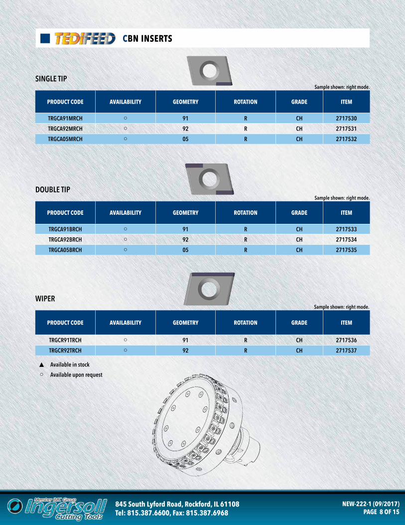
CBN INSERTS
▲ Available in stock
○ Available upon request
PRODUCT CODE AVAILABILITY GEOMETRY ROTATION GRADE ITEM
TRGCA91MRCH ○ 91 R CH 2717530
TRGCA92MRCH ○ 92 R CH 2717531
TRGCA05MRCH ○ 05 R CH 2717532
PRODUCT CODE AVAILABILITY GEOMETRY ROTATION GRADE ITEM
TRGCA91BRCH ○ 91 R CH 2717533
TRGCA92BRCH ○ 92 R CH 2717534
TRGCA05BRCH ○ 05 R CH 2717535
SINGLE TIP
DOUBLE TIP
Sample shown: right mode.
Sample shown: right mode.
PRODUCT CODE AVAILABILITY GEOMETRY ROTATION GRADE ITEM
TRGCR91TRCH ○ 91 R CH 2717536
TRGCR92TRCH ○ 92 R CH 2717537
WIPERSample shown: right mode.
845 South Lyford Road, Rockford, IL 61108Tel: 815.387.6600, Fax: 815.387.6968
NEW-222-1 (09/2017)PAGE 9 OF 15
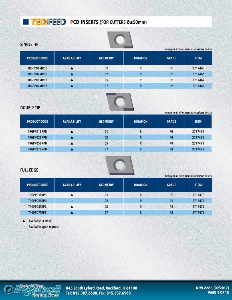
PCD INSERTS (FOR CUTTERS Ø≤50mm)
▲ Available in stock
○ Available upon request
PRODUCT CODE AVAILABILITY GEOMETRY ROTATION GRADE ITEM
TRGPP01MRPB ▲ 01 R PB 2717465
TRGPP02MRPB ▲ 02 R PB 2717466
TRGPP05MRPB ▲ 05 R PB 2717467
TRGPP07MRPB ▲ 07 R PB 2717468
PRODUCT CODE AVAILABILITY GEOMETRY ROTATION GRADE ITEM
TRGPP01BRPB ▲ 01 R PB 2717469
TRGPP02BRPB ▲ 02 R PB 2717470
TRGPP05BRPB ▲ 05 R PB 2717471
TRGPP07BRPB ▲ 07 R PB 2717472
Immagine di riferimento: rotazione destra
Immagine di riferimento: rotazione destra
PRODUCT CODE AVAILABILITY GEOMETRY ROTATION GRADE ITEM
TRGPP01TRPB ▲ 01 R PB 2717473
TRGPP02TRPB ○ 02 R PB 2717474
TRGPP05TRPB ▲ 05 R PB 2717475
TRGPP07TRPB ▲ 07 R PB 2717476
Immagine di riferimento: rotazione destra
SINGLE TIP
DOUBLE TIP
FULL EDGE
845 South Lyford Road, Rockford, IL 61108Tel: 815.387.6600, Fax: 815.387.6968
NEW-222-1 (09/2017)PAGE 10 OF 15
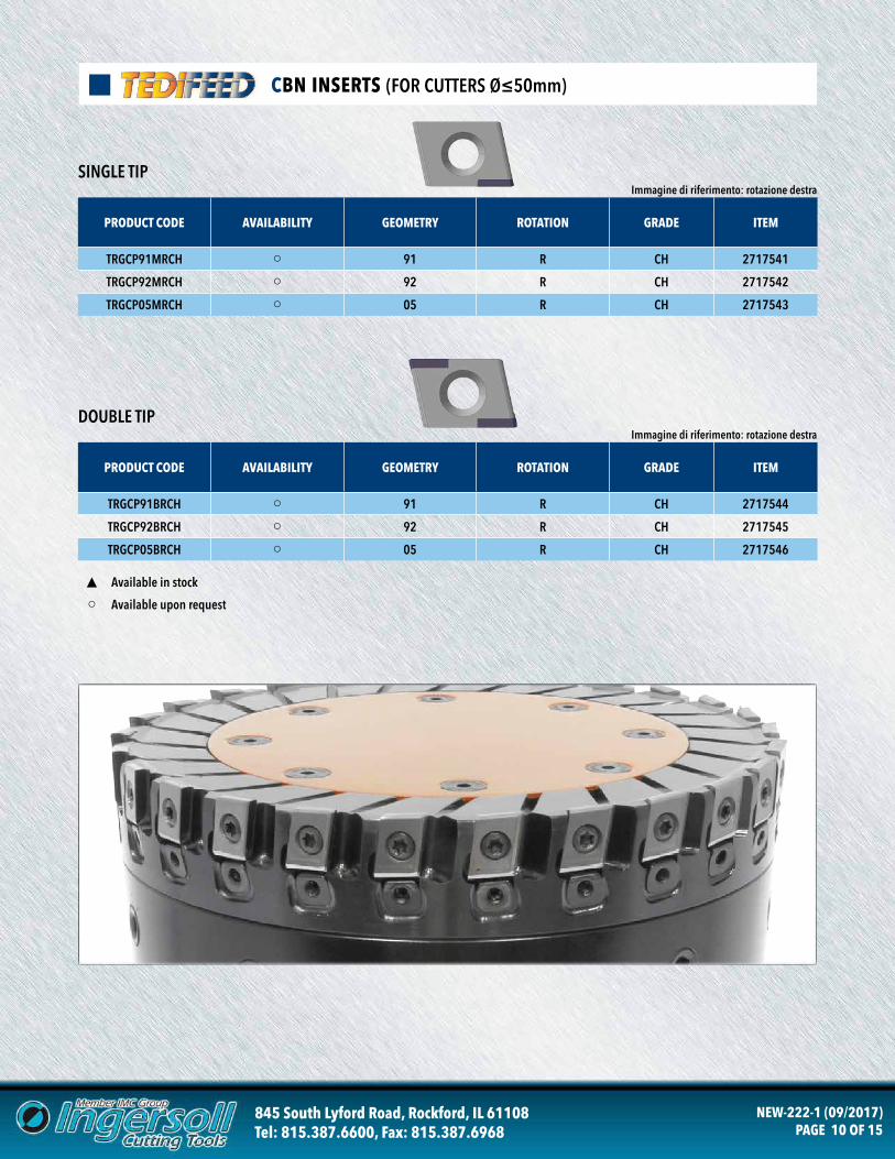
CBN INSERTS (FOR CUTTERS Ø≤50mm)
▲ Available in stock
○ Available upon request
PRODUCT CODE AVAILABILITY GEOMETRY ROTATION GRADE ITEM
TRGCP91MRCH ○ 91 R CH 2717541
TRGCP92MRCH ○ 92 R CH 2717542
TRGCP05MRCH ○ 05 R CH 2717543
PRODUCT CODE AVAILABILITY GEOMETRY ROTATION GRADE ITEM
TRGCP91BRCH ○ 91 R CH 2717544
TRGCP92BRCH ○ 92 R CH 2717545
TRGCP05BRCH ○ 05 R CH 2717546
Immagine di riferimento: rotazione destra
Immagine di riferimento: rotazione destra
SINGLE TIP
DOUBLE TIP
845 South Lyford Road, Rockford, IL 61108Tel: 815.387.6600, Fax: 815.387.6968
NEW-222-1 (09/2017)PAGE 11 OF 15
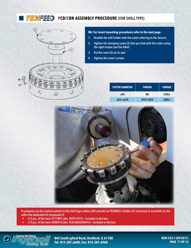
PCD/CBN ASSEMBLY PROCEDURE (FOR SHELL TYPE)
5
6
To properly use the coolant system on the shell type cutters ø50 and ø63 on TEDIMILL’s holder, it’s necessary to assemble on the cutter the dedicated kit composed of:• n°2 pcs. of the item 2717081 (des. RSFTC1012) - included in the box• n°2 pcs. of the item 4300414 (des. VC010642I04015) - included in the box
NB: For insert mounting procedures refer to the next page
1. Asseble the mill holder with the cutter referring to the drivers;
2. Tighten the clamping screw (5) that you find with the cutter using the right torque (see the label)
3. Put the cover (6) on its seat
4. Tighten the cover’s screws
CUTTER DIAMETER THREAD TORQUE
ø40 M6 23Nm
ø50÷ø250 M10÷M20 60Nm
845 South Lyford Road, Rockford, IL 61108Tel: 815.387.6600, Fax: 815.387.6968
NEW-222-1 (09/2017)PAGE 12 OF 15
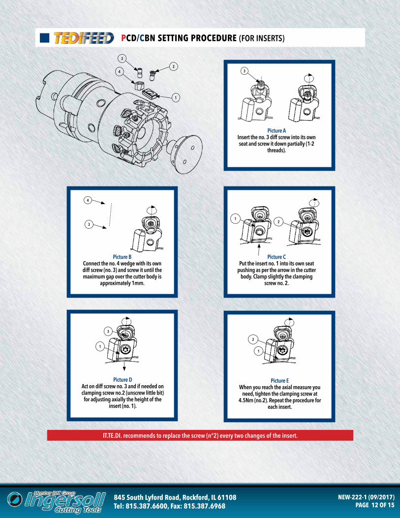
PCD/CBN SETTING PROCEDURE (FOR INSERTS)
1
2
3
4
4
3
3
1
IT.TE.DI. recommends to replace the screw (n°2) every two changes of the insert.
3
Picture AInsert the no. 3 diff screw into its own seat and screw it down partially (1-2
threads).
Picture BConnect the no. 4 wedge with its own diff screw (no. 3) and screw it until the maximum gap over the cutter body is
approximately 1mm.
Picture DAct on diff screw no. 3 and if needed on clamping screw no.2 (unscrew little bit) for adjusting axially the height of the
insert (no. 1).
1
2
Picture EWhen you reach the axial measure you
need, tighten the clamping screw at 4.5Nm (no.2). Repeat the procedure for
each insert.
12
Picture CPut the insert no. 1 into its own seat
pushing as per the arrow in the cutter body. Clamp slightly the clamping
screw no. 2.
845 South Lyford Road, Rockford, IL 61108Tel: 815.387.6600, Fax: 815.387.6968
NEW-222-1 (09/2017)PAGE 13 OF 15
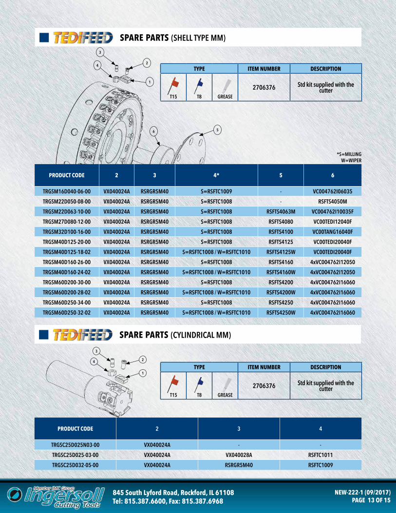
SPARE PARTS (SHELL TYPE MM)
1
2
3
4
PRODUCT CODE 2 3 4
TRGSC25D025N03-00 VX040024A - -
TRGSC25D025-03-00 VX040024A VX040028A RSFTC1011
TRGSC25D032-05-00 VX040024A RSRGR5M40 RSFTC1009
1
2
3
4
56
TYPE ITEM NUMBER DESCRIPTION
T15 T8 GREASE
2706376 Std kit supplied with the cutter
TYPE ITEM NUMBER DESCRIPTION
T15 T8 GREASE
2706376 Std kit supplied with the cutter
*S=MILLING W=WIPER
SPARE PARTS (CYLINDRICAL MM)
PRODUCT CODE 2 3 4* 5 6
TRGSM16D040-06-00 VX040024A RSRGR5M40 S=RSFTC1009 - VC004762I06035
TRGSM22D050-08-00 VX040024A RSRGR5M40 S=RSFTC1008 - RSFTS4050M
TRGSM22D063-10-00 VX040024A RSRGR5M40 S=RSFTC1008 RSFTS4063M VC004762I10035F
TRGSM27D080-12-00 VX040024A RSRGR5M40 S=RSFTC1008 RSFTS4080 VC00TEDI12040F
TRGSM32D100-16-00 VX040024A RSRGR5M40 S=RSFTC1008 RSFTS4100 VC00TANG16040F
TRGSM40D125-20-00 VX040024A RSRGR5M40 S=RSFTC1008 RSFTS4125 VC00TEDI20040F
TRGSM40D125-18-02 VX040024A RSRGR5M40 S=RSFTC1008 / W=RSFTC1010 RSFTS4125W VC00TEDI20040F
TRGSM40D160-26-00 VX040024A RSRGR5M40 S=RSFTC1008 RSFTS4160 4xVC004762I12050
TRGSM40D160-24-02 VX040024A RSRGR5M40 S=RSFTC1008 / W=RSFTC1010 RSFTS4160W 4xVC004762I12050
TRGSM60D200-30-00 VX040024A RSRGR5M40 S=RSFTC1008 RSFTS4200 4xVC004762I16060
TRGSM60D200-28-02 VX040024A RSRGR5M40 S=RSFTC1008 / W=RSFTC1010 RSFTS4200W 4xVC004762I16060
TRGSM60D250-34-00 VX040024A RSRGR5M40 S=RSFTC1008 RSFTS4250 4xVC004762I16060
TRGSM60D250-32-02 VX040024A RSRGR5M40 S=RSFTC1008 / W=RSFTC1010 RSFTS4250W 4xVC004762I16060
845 South Lyford Road, Rockford, IL 61108Tel: 815.387.6600, Fax: 815.387.6968
NEW-222-1 (09/2017)PAGE 14 OF 15
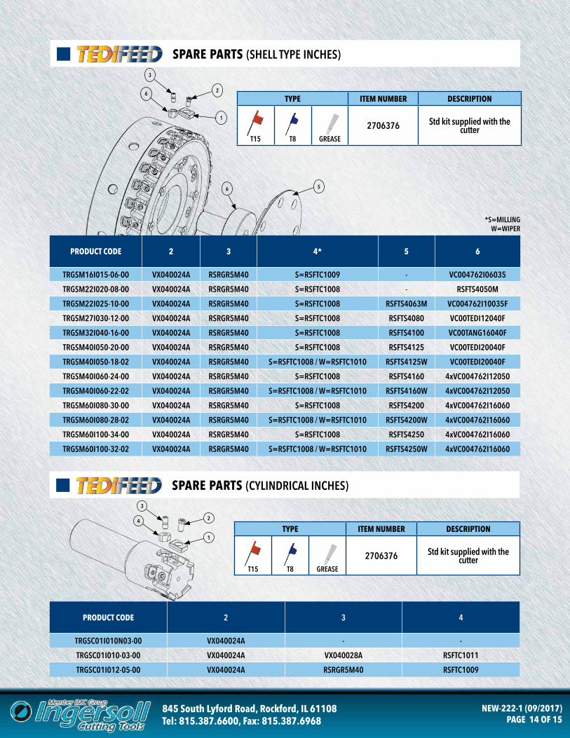
SPARE PARTS (SHELL TYPE INCHES)
SPARE PARTS (CYLINDRICAL INCHES)
1
2
3
4
PRODUCT CODE 2 3 4
TRGSC01I010N03-00 VX040024A - -
TRGSC01I010-03-00 VX040024A VX040028A RSFTC1011
TRGSC01I012-05-00 VX040024A RSRGR5M40 RSFTC1009
1
2
3
4
56
TYPE ITEM NUMBER DESCRIPTION
T15 T8 GREASE
2706376 Std kit supplied with the cutter
TYPE ITEM NUMBER DESCRIPTION
T15 T8 GREASE
2706376 Std kit supplied with the cutter
*S=MILLING W=WIPER
PRODUCT CODE 2 3 4* 5 6
TRGSM16I015-06-00 VX040024A RSRGR5M40 S=RSFTC1009 - VC004762I06035
TRGSM22I020-08-00 VX040024A RSRGR5M40 S=RSFTC1008 - RSFTS4050M
TRGSM22I025-10-00 VX040024A RSRGR5M40 S=RSFTC1008 RSFTS4063M VC004762I10035F
TRGSM27I030-12-00 VX040024A RSRGR5M40 S=RSFTC1008 RSFTS4080 VC00TEDI12040F
TRGSM32I040-16-00 VX040024A RSRGR5M40 S=RSFTC1008 RSFTS4100 VC00TANG16040F
TRGSM40I050-20-00 VX040024A RSRGR5M40 S=RSFTC1008 RSFTS4125 VC00TEDI20040F
TRGSM40I050-18-02 VX040024A RSRGR5M40 S=RSFTC1008 / W=RSFTC1010 RSFTS4125W VC00TEDI20040F
TRGSM40I060-24-00 VX040024A RSRGR5M40 S=RSFTC1008 RSFTS4160 4xVC004762I12050
TRGSM40I060-22-02 VX040024A RSRGR5M40 S=RSFTC1008 / W=RSFTC1010 RSFTS4160W 4xVC004762I12050
TRGSM60I080-30-00 VX040024A RSRGR5M40 S=RSFTC1008 RSFTS4200 4xVC004762I16060
TRGSM60I080-28-02 VX040024A RSRGR5M40 S=RSFTC1008 / W=RSFTC1010 RSFTS4200W 4xVC004762I16060
TRGSM60I100-34-00 VX040024A RSRGR5M40 S=RSFTC1008 RSFTS4250 4xVC004762I16060
TRGSM60I100-32-02 VX040024A RSRGR5M40 S=RSFTC1008 / W=RSFTC1010 RSFTS4250W 4xVC004762I16060
845 South Lyford Road, Rockford, IL 61108Tel: 815.387.6600, Fax: 815.387.6968
NEW-222-1 (09/2017)PAGE 15 OF 15
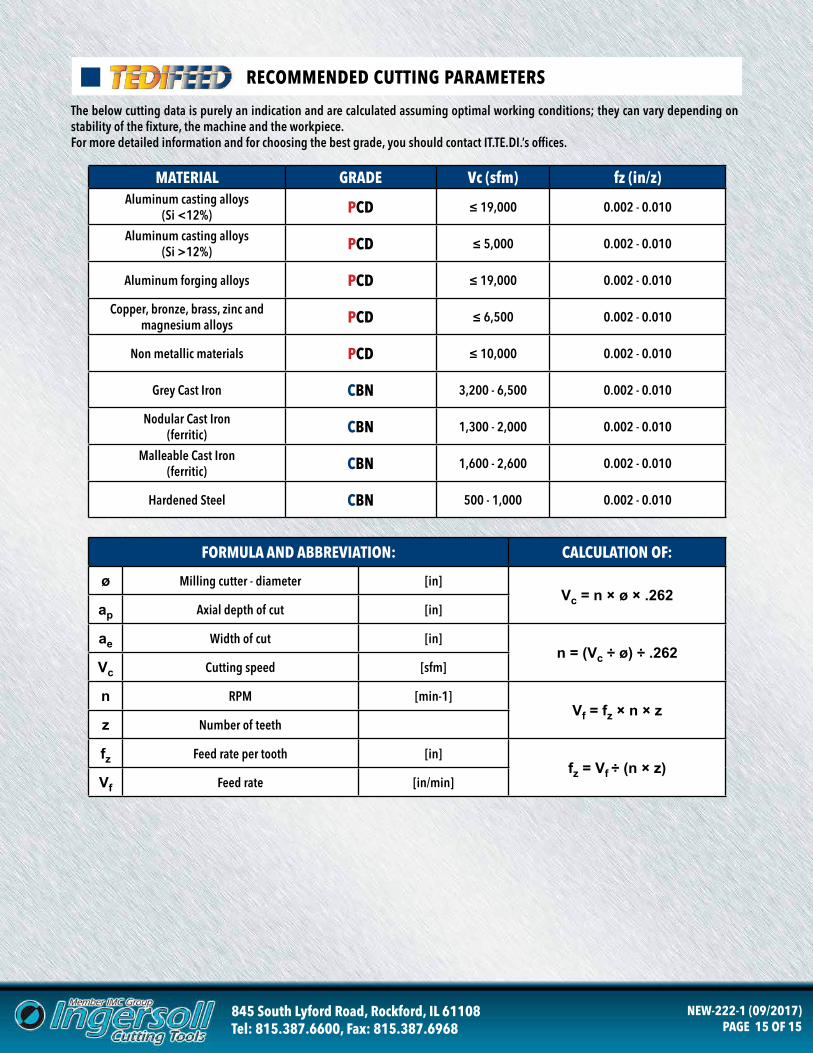
RECOMMENDED CUTTING PARAMETERS
MATERIAL GRADE Vc (sfm) fz (in/z)Aluminum casting alloys
(Si <12%) PCD ≤ 19,000 0.002 - 0.010
Aluminum casting alloys(Si >12%) PCD ≤ 5,000 0.002 - 0.010
Aluminum forging alloys PCD ≤ 19,000 0.002 - 0.010
Copper, bronze, brass, zinc and magnesium alloys PCD ≤ 6,500 0.002 - 0.010
Non metallic materials PCD ≤ 10,000 0.002 - 0.010
Grey Cast Iron CBN 3,200 - 6,500 0.002 - 0.010
Nodular Cast Iron(ferritic) CBN 1,300 - 2,000 0.002 - 0.010
Malleable Cast Iron(ferritic) CBN 1,600 - 2,600 0.002 - 0.010
Hardened Steel CBN 500 - 1,000 0.002 - 0.010
The below cutting data is purely an indication and are calculated assuming optimal working conditions; they can vary depending on stability of the fixture, the machine and the workpiece.For more detailed information and for choosing the best grade, you should contact IT.TE.DI.’s offices.
FORMULA AND ABBREVIATION: CALCULATION OF:
ø Milling cutter - diameter [in]Vc = n × ø × .262
ap Axial depth of cut [in]
ae Width of cut [in]n = (Vc ÷ ø) ÷ .262
Vc Cutting speed [sfm]
n RPM [min-1]Vf = fz × n × z
z Number of teeth
fz Feed rate per tooth [in]fz = Vf ÷ (n × z)
Vf Feed rate [in/min]