Embed Size (px)
Citation preview
PC Construction and Maintenance
Week 3
The Processing System
CPU, Motherboard, RAM and the BIOS
Motherboards
• The motherboard (a.k.a mainboard) is the main large circuit board within the computer
• The type and configuration of the motherboard is crucial to the performance of the computer
• Most motherboards comply with many different standards, allowing interchangeable components and upgrading
• Practically, all other components inside the PC connect to the motherboard. It interconnects devices
Motherboard features
• Many features common to all motherboards• Important to have an understanding of the
function of each feature, and how to identify them
• Most important feature is probably the CPU socket, or slot
• Type of board dictates what brand of processors can fit in it
Power Connectors
• The motherboard is powered directly from the PSU
• The PSU provides a selection of different voltages –12v, -5v, +5v, +12v etc
• ATX motherboards have a 20-pin connector that allows insertion of plug only the correct way round
• AT boards use two separate 6-pin connectors. Must be connected with black wires adjacent to each other, in the centre
Memory Slots - DIMM
• DIMM slots are the most common• DIMM RAM available in a range of
different capacities• RAM also has a speed rating, the maximum
speed it can run as• Example speeds are PC100, PC133 etc.• Fast RAM can be used on slow boards, but
not the other way round
Memory slots – SIMM
• SIMM slots are found on older boards• SIMM memory is slower than DIMM• On many boards, SIMM RAM has to be
populated in pairs• The two main types of SIMM memory are
standard, and EDO• EDO is faster, and can be used on all SIMM
enabled boards
On-board Jumpers
• Jumpers are used to configure some motherboards
• Some newer boards are ‘jumperless’, they allow configuration via the system BIOS instead
• Care must be taken to ensure that jumper settings are correct, before powering up the machine
Northbridge Chipset
• The northbridge chipset is central to the operation of the PC. It is also referred to as the system bus controller
• The northbridge chipset often runs quite hot, and usually has a heatsink. Newer boards have a fan attached to this chip
• The Northbridge chipset controls the flow of data to and from the system memory
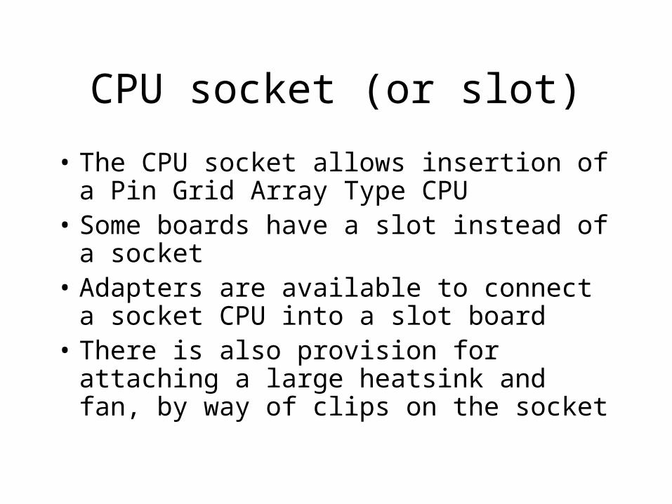
CPU socket (or slot)
• The CPU socket allows insertion of a Pin Grid Array Type CPU
• Some boards have a slot instead of a socket• Adapters are available to connect a socket
CPU into a slot board• There is also provision for attaching a large
heatsink and fan, by way of clips on the socket
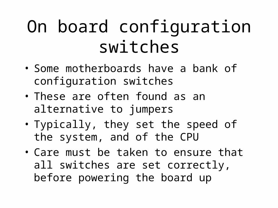
On board configuration switches
• Some motherboards have a bank of configuration switches
• These are often found as an alternative to jumpers• Typically, they set the speed of the system, and of
the CPU• Care must be taken to ensure that all switches are
set correctly, before powering the board up
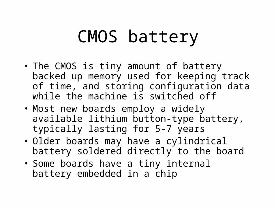
CMOS battery
• The CMOS is tiny amount of battery backed up memory used for keeping track of time, and storing configuration data while the machine is switched off
• Most new boards employ a widely available lithium button-type battery, typically lasting for 5-7 years
• Older boards may have a cylindrical battery soldered directly to the board
• Some boards have a tiny internal battery embedded in a chip
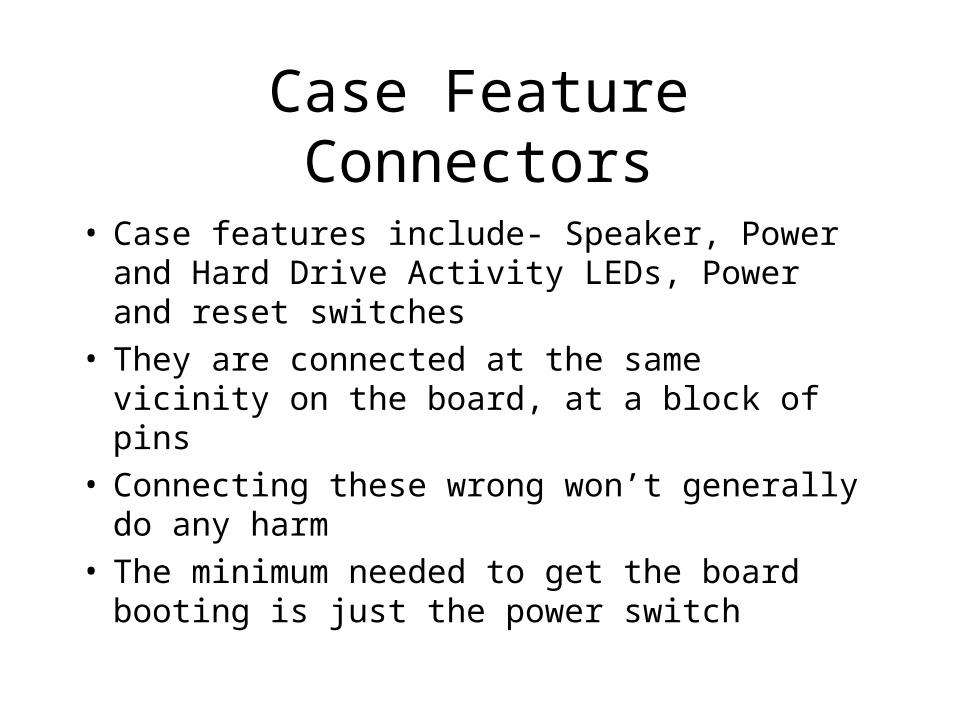
Case Feature Connectors
• Case features include- Speaker, Power and Hard Drive Activity LEDs, Power and reset switches
• They are connected at the same vicinity on the board, at a block of pins
• Connecting these wrong won’t generally do any harm
• The minimum needed to get the board booting is just the power switch
BIOS chip
• This chip contains the low-level software (firmware) that controls the basic features of the machine
• The user can enter the BIOS software at boot time, typically by pressing the delete key
• The BIOS software can often be upgraded (flashed) via a small DOS program
• The most common BIOS software in current use is the ‘AWARD’ BIOS
• There are many different BIOS manufacturers (AMIBIOS, Intel etc..)
ISA slots
• These slots run at a very slow speed by today's standards
• Typically used for older peripheral devices• Extended variant of ISA still found on some old
machines, known as VESA local bus (VLB). That standard has been made obsolete by the newer and better PCI standard
• New motherboards may not have ISA slots, although a single slot is common
PCI slots
• These slots are used for most current peripheral devices
• Expect to find between 3 and 6 of these slots on most boards
• Each card plugged into a slot uses a ‘resource’• Resources are limited, so there is no guarantee that
every slot can be used at the same time (this is becoming less true for new hardware)

AGP slot
• The Advanced Graphics Processor slot accepts video cards
• Although PCI video cards are also available, AGP cards are faster
• AGP has become the standard for fast graphics devices
• Motherboards typically only have a single AGP slot• Some cheap motherboards have ‘on-board AGP
graphics’. Generally, to be avoided, as these boards often lack an AGP slot
IDE Hard Disk connectors
• Most motherboards have two IDE HDD connectors. Each connector accepts a two-way or three way cable
• Each connector provides one IDE channel• A single IDE channel can support two IDE devices.
One is master, the other slave• Therefore, most boards support up to 4 IDE devices.
Boards that accept less are rare• Some new boards support 4 IDE channels (8
devices). Average home user probably wouldn’t need this many
IDE hard disk connectors
• The IDE connectors have 40-pins.• The connecting lead must be inserted the correct way
round• In PC building, red usually indicates ‘pin 1’• Ensure the red part of the lead lines up with pin one on
the motherboard• New IDE leads have 80 conductors instead of 40, but
still have 40 pins.• 40 pin connectors will work with any IDE device, but
fast hard drives will suffer a speed penalty unless 80-conductor cables are used.
Floppy Drive connector
• All boards have a Floppy Drive connector (FDC)• The standard connector has 34 pins and supports
two floppy type devices• One device is designated A:, and one B:• Floppy cables have a twist in them. Device A: is
always plugged in at the very end of the cable, beyond the twist. Device B: is connected in the middle, before the twist
• Pin 1 must be correctly aligned, or the drive won’t work
Other Connectors
• Most new ATX boards have external PS/2 keyboard, PS/2 mouse, serial and parallel I/O connections directly on the board.
• Older boards have internal connections on the board that must be connected to external backplates via a variety of ribbon cables
• In each case, pin 1 must be aligned correctly• Some old motherboards have serial connections that
are wired differently than others, and therefore must be supplied with the correct backplate.
The central processing unit
• The processor must be compatible with the motherboard
• Physical compatibility is essential, but is only half the story
• The Motherboard must be capable of supplying the correct voltages to the CPU
• The motherboard must be able to run at the correct speeds for the CPU
CPU Parameters - Speed
• Clock Speed – This is rating of the maximum speed that the core of the CPU can run at reliably
• Speed is measured in MHz (becoming GHz), meaning millions (or billions) of cycles per second
• The motherboard controls the speed the CPU runs at, and can regulate this speed
• The CPU should not be run at higher than the specified speed (known as overclocking) or, permanent damage can result
CPU paramters - FSB
• The Front side Bus (FSB) is the CPUs interface with the motherboard
• The speed of the FSB is measured in MHz, and is always lower than the CPU core speed.
• The motherboard uses a device known as a ‘clock multiplier’ to derive the CPU core speed from the FSB speed
The clock multiplier
• The speed of the core and the FSB of any CPU are related by the following expression.
CORESPEED=FSBSPEED*MULTIPLIER
Because of the electronic nature of the frequency multiplying circuitry, the value of the multiplier is usually a whole number, or a whole number and a
half
Clock multiplier settings
• The clock multiplier is normally set by motherboard jumpers, switches, or in new machines in a BIOS submenu
• Typical values for the multiplier settings are x2,x2.5,x3 etc..
• The multiplier settings must be set correctly such that the chip runs at the designed speed
Other CPU Parameters
• Power consumption is another factor that is important, and becoming increasingly so
• The PSU must be able to supply enough power to the CPU plus motherboard and all peripheral devices
• Modern processors can consume 55watts of power• Most of this energy is dissipated as heat• The cooling system must be capable of dissipating
this heat, or the machine will likely crash
CPU Parameters
• Operating temperature of the CPU is an important factor• Different manufacture’s chips run at different
temperaturs• In general Faster=Hotter• A typical modern day CPU may run at around 55 deg. C• Anything above 70 deg. C could result in damage to the
chip• Typically the running temperature can be observed via
the BIOS software
CPU parameters
• Form factor describes the shape of the chip, and how it connects to the motherboard
• The two most common types are PGA, Pin Grid Array (a.k.a the socket type) and Slot type chips
• Even different types of PGA chips can have different numbers of pins (in general, newer=more pins), but processors of the same generation are expected to have the same number of pins
Form Factor Considerations
• A form factor of a chip that is compatible with a particular motherboard does not guarantee compatibility between board and chip
• E.g Intel’s Slot 1 and AMD’s slot A are physically identical, but are electrically incompatible
• Because different manufacturer’s chips, and different generations of chips run at different voltages etc.. it is often necessary to buy a new motherboard when upgrading the CPU
CPU voltages
• In general newer chips contain larger numbers of components etched onto the sillicon wafer
• This calls for scaling down of the “feature size” of the CPUs over time
• Smaller feature size calls for lower voltages• The operating voltage of the components inside the CPU
is known as the “Core Voltage”• The core voltage is controlled by the motherboard BIOS,
and must be set correct for the CPU to function correctly• Most new machines configure this automatically

CPU – the market
• Two or three manufactures dominate the CPU market
• The big two are Intel and AMD• Recommend the AMD athlon processor at the
moment• Athlon far cheaper than Intel’s Pentium 4• Best Buy ‘Swings like a pendulum’, sometimes
AMD chips lag behind Intel chips in terms of performance.
Introducing the BIOS
• Enter the BIOS by pressing delete on most computers (F1 or F2 key on some machines – notably laptops)
• Using the BIOS, you can set the system time and configure hardware parameters
• The current BIOS settings are preserved in a special area called the CMOS, a battery backed area of memory
The main menu
• The main BIOS menu contains a dozen submenus
• Navigation around menus is via Arrow keys. There are some Function key shortcuts available
• The “page up” and “page down” keys are used to change BIOS settings
• A mouse is not needed at this stage
The Award BIOS
• AWARD currently develop most of the worlds BIOS software
• Most of the features found in the AWARD BIOS are common to all BIOS types
• AWARD BIOS has a user friendly but powerful interface
• Standard methods are used to update the AWARD BIOS when needed
Standard CMOS Setup
• Use this menu to set the on board system clock. Usually this needs to be done after purchasing a brand new motherboard, or after failure of a battery
• This menu is also used to view/change hard drive parameters
• Floppy drive devices are configured here. It is very rare though, that these parameters are changed
• Finally, Video mode for the BIOS itself can be selected as well as the halt conditions. Again, these parameters are not usually altered
SpeedEasy CPU setup
• For motherboards that do not use jumpers or switches on the board, the speed of the CPU can be set here. Either directly, or via setting FSB speed and multiplier explicitly
• Some BIOS versions have these settings under the “chipset features” menu instead
• Another setting here is that of the RAM. The RAM speed can typically run at the same speed as the FSB, but depending on the type, it may be set to run faster than the FSB.
BIOS features setup
• Most of these feature can be left as the factory defaults
• Important settings are “Boot sequence” which determines the order of devices that the machine will attempt to boot from
• Often, the BIOS password can be set between two modes, setup and system. Setup means that a password is required to change BIOS settings. System means that a password is required to use the computer
Chipset features setup
• Here, you can alter the memory timing parameters. It is possible to get a small extra burst of speed by playing around with these parameters. Normally, probably best to leave them at default settings
• AGP and USB settings can also be found here Again, unless there is a reason to change the defaults, probably best to leave alone
Power management setup
• These options allow the extent and modes of power saving
• All modern computers have the facility to shut down various systems after periods of idleness, in order to conserve power
• The behaviour of the power button can be changed here also, from instant-off to several-second delay.
PnP/PCI Configuration
• This menu is important when using legacy hardware
• Normally, the default setting of “Resources controlled by Auto” works with modern “Plug’n’Play” hardware
• Some older operating systems do not support PnP, so turn it off in that case
• For windows 95/98/2000 set “PNP OS installed” to Yes
Load Setup defaults
• Sometimes, when tweaking settings in the BIOS, it is possible to accidentally mess things up. This setting allows the factory defaults to be restored
• Loading the default parameter set will not run the computer in its most optimal mode, but will provide the most stable and reliable mode of operation
Integrated peripherals menu
• This menu enables/disables and configures the peripheral devices that are directly on the motherboard
• IDE channels, Parallel and Serial ports can be enabled/disabled here
• Normally, all the device should be enabled, but may occasionally have to be disable due to conflicts with add-on hardware etc. E.g. older modems can conflict with the on-board serial ports
System Monitor
• Newer computer tend to use faster chips that generate a lot of unwanted heat, and consume a lot of power
• This menu allows you to monitor the temperature of the CPU, motherboard etc.
• This is useful if overheating is suspected• System voltages are also displayed in this menu,
and so overloading of the PSU would reveal itself here
Password Setting
• You can allocate a password to prevent unauthorized tampering
• This is not water-tight, as software programs exists that ‘crack’ the password
• To reset an unknown password, change a motherboard jumper to reset the CMOS, or knock the battery out for a couple of minutes
IDE HDD Auto detection
• This menu is typically used after installing a hard drive for the first time, or adding a new hard drive
• Hard drives have many operating parameters that need to be set right for the drive to function properly
• On very old computers, this info had to be entered into the BIOS by hand, but all modern systems support autodetection, making things a lot easier for the PC builder.
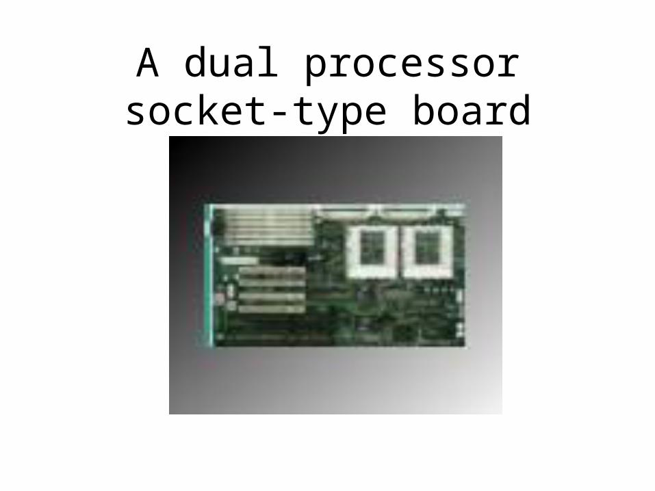
A dual processor socket-type board
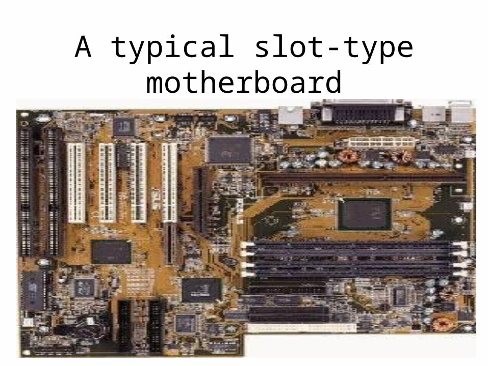
A typical slot-type motherboard