Embed Size (px)
Citation preview
HP WMT-LX Manual 1
WMT-LXIntel® 850 ATX Motherboard
Manual
SPECIFICATIONS AND INFORMATION CONTAINED IN THIS MANUAL ARE FURNISHEDFOR INFORMATIONAL USE ONLY, AND ARE SUBJECT TO CHANGE AT ANY TIME WITH-OUT NOTICE, AND SHOULD NOT BE CONSTRUED AS A COMMITMENT BY ASUSTeKCOMPUTER INC. ASUS ASSUMES NO RESPONSIBILITY OR LIABILITY FOR ANYERRORS OR INACCURACIES THAT MAY APPEAR IN THIS MANUAL, INCLUDING THEPRODUCTS AND SOFTWARE DESCRIBED IN IT.
Copyright © 2001 ASUSTeK COMPUTER INC. All Rights Reserved.
Product Name: HP WMT-LX
Release Date: 2001
+001-006 WMT_01.p65 3/22/01, 4:28 PM1

2 HP WMT-LX Manual
1. FEATURES1.1 WMT-LX Motherboard Layout
RJ-45Top:
24.4cm (9.60in)
24.4
cm (
9.6i
n)
PS/2KBMST: MouseB: Keyboard
PCI1
PCI2
PCI3 PANEL
FLO
PP
Y
SE
CO
ND
AR
Y ID
E
PR
IMA
RY
IDE
Intel I/OController
Hub(ICH2)
WMT-LX
Accelerated Graphics Port (AGP)
CR2032 3VLithium Cell
CMOS Power
Socket 423
COM1
PAR
AL
LE
L P
OR
T
RIM
MB
2 (16/18 bit, 184-pin module)
RIM
MB
1 (1
6/1
8 b
it, 18
4-p
in m
od
ule
)
AT
X P
ower
Con
nect
or
RIM
MA
2 (16/18 bit, 184-pin module)
RIM
MA
1 (1
6/1
8 b
it, 18
4-p
in m
od
ule
)
MultiI/O
ATX12V
Intel 850Memory
ControllerHub (MCH)
USB1USB2
Top:
RealtekRTL8139C
CPU_FAN
PWR_FAN
USB2/3CLRTC
HPBIOS
WOLCON
1394 HEAD
IEEE1394
1394Physical
LayerChip
1394Link
LayerChip
RJ-45Bottom:
Grayed components are available only on certain models at the time of purchase.
+001-006 WMT_01.p65 3/22/01, 4:28 PM2

HP WMT-LX Manual 3
1.2 Layout ContentsExpansion1) RIMMA1/A2/B1/B2 p. 5 184-Pin System Memory Support2) CPU p. 7 Central Processing Unit3) PCI1/2/3/ p. 12 32-bit PCI Bus Expansion Slots4) AGPPRO p. 13 Accelerated Graphics Port Slot
Connectors1) PS2MS p.14 PS/2 Mouse Connector (Green 6-pin female)2) PS2KB p.14 PS/2 Keyboard Connector (Purple 6-pin female)3) PRINTER p.15 Parallel Port Connector (Burgundy 25-pin female)4) COM1 p.15 Serial Port Connectors (Turquoise 10-1 pin male)5) 1394_CON p.15 IEEE-1394 Controller Interface Connector (6-pin male)6) USB p.16 Universal Serial Bus Ports (Black two 4-pin female)7) RJ45 p.16 Fast-Ethernet Port Connector (female)8) PRIMARY/SECONDARY IDE p.17 Primary/Secondary IDE Connectors (Two 40-1pin)9) FLOPPY p.18 Floppy Disk Drive Connector (34-1pin)10) 1394HEAD2/1394HEAD3 p.18 IEEE-1394 Headers (8-pin)11) CPU_FAN, PWR_FAN p.19 POWER, CPU Fan Connectors (3 pin)12) WOL p.20 Wake-On-LAN Connector (3 pin)13) USB2/3 p.20 USB Header (10-1 pin)14) ATXPWR, AUXPWR, p.21 ATX 12V Power Supply Connectors
ATX12V15) PWR (PANEL) p.22 ATX Power / Soft-Off Switch Lead (2 pin)16) IDELED (PANEL) p.22 IDE Activity LED (2 pin)17) PLED (PANEL) p.22 System Power LED Lead (3-1 pin)18) RESET (PANEL) p.22 Reset Switch Lead (2 pin)19) MLED (PANEL) p.22 System Message LED (2 pin)20) KEYLOCK (PANEL) p.22 Keyboard Lock Switch Lead (2 pin)21) SMI (PANEL) p.22 System Management Interrupt Switch Lead (2 pin)22) SPEAKER (PANEL) p.22 System Warning Speaker Connector (4 pin)23) RTC p.23 Real Time Clock Jumper
1. FEATURES
+001-006 WMT_01.p65 3/22/01, 4:28 PM3

4 HP WMT-LX Manual
2. HARDWARE SETUP2.1 Getting StartedIMPORTANT: Due to Pentium 4 CPU’s power consumption requirement, anATX12V power supply is recommended for this motherboard. For typical systemconfigurations, an ATX12V power supply that can supply at least 230W and at least8.5A on the +12V lead is required. For heavily-loaded configurations, an ATX12Vpower supply that can supply at least 300W is required.
Before using your computer, you must complete the following steps:
• Check Motherboard Settings• Install Memory Modules• Install the Central Processing Unit (CPU)• Install Expansion Cards• Connect Ribbon Cables, Panel Wires, and Power Supply
WARNING! Computer motherboards and expansion cards contain very delicateIntegrated Circuit (IC) chips. To protect them against damage from static electric-ity, you should follow some precautions whenever you work on your computer.
1. Unplug your computer when working on the inside.2. Use a grounded wrist strap before handling computer components. If you do
not have one, touch both of your hands to a safely grounded object or to a metalobject, such as the power supply case.
3. Hold components by the edges and try not to touch the IC chips, leads or con-nectors, or other components.
4. Place components on a grounded antistatic pad or on the bag that came with thecomponent whenever the components are separated from the system.
5. Ensure that the ATX power supply is switched off before you plug in orremove the ATX power connector on the motherboard.
WARNING! Make sure that you unplug your power supply when adding orremoving system components. Failure to do so may cause severe damage toyour motherboard, peripherals, and/or components. The onboard LED whenlit acts as a reminder that the system is in suspend or soft-off mode and notpowered OFF.
+001-006 WMT_01.p65 3/22/01, 4:28 PM4

HP WMT-LX Manual 5
2. HARDWARE SETUP2.2 System MemoryNOTE: No hardware or BIOS setup is required after adding or removing memory.This motherboard has four 184-pin Rambus Inline Memory Modules (RIMM) sockets.These sockets support 64Mbit, 128Mbit, and 256Mbit Direct RDRAM technologies.
IMPORTANT1. The memory configuration of channel A (RIMMA1 and RIMMA2) and chan-
nel B (RIMMB1 and RIMMB2) must be identical (see below).2. C-RIMMs (Continuity RIMM) must be used to complete the sockets that are
not populated by RDRAMs. A C-RIMM is necessary to avoid breaking thesignal lines, which are a serial connection in a Rambus interface, such asused in this motherboard. This assures the electrical integrity of a Rambusinterface.
3. When C-RIMMs are required, it is recommended that they be inserted intoRIMMA2 and RIMMB2.
RIMMA1RIMMA2
RIMMB1RIMMB2
128MB RDRAM
128MB RDRAMC-RIMM
C-RIMM
a.
RIMMA1RIMMA2
RIMMB1RIMMB2
128MB RDRAM
128MB RDRAM
128MB RDRAM
128MB RDRAMc.
RIMMA1RIMMA2
RIMMB1RIMMB2
128MB RDRAM
128MB RDRAMC-RIMM
C-RIMM
b.
Location Memory Module Subtotal
RIMMA1 RDRAM x 1(Rows 0&1) C-RIMM (use when socket will not be populated)
RIMMA2 RDRAM x 1(Rows 2&3) C-RIMM (use when socket will not be populated)
RIMMB1 RDRAM x 1(Rows 4&5) C-RIMM (use when socket will not be populated)
RIMMB2 RDRAM x 1(Rows 6&7) C-RIMM (use when socket will not be populated)
TOTAL SYSTEM MEMORY =(2GB Max)
NOTE: When using only two memory modules,it is recommended that you use configuration a.
+001-006 WMT_01.p65 3/22/01, 4:28 PM5

6 HP WMT-LX Manual
2. HARDWARE SETUP2.2.1 Installing MemoryThe memory module (RIMM/C-RIMM) will fit in only one orientation.
IMPORTANT: Do not touch the memory module’s connectors. Handle the mod-ule only by the edges.
1. Make sure that the notch keys in the module are aligned with the small ribsinside the RIMM sockets.
NOTCH KEYS
CONNECTORS
RDRAM (with heat spreader)MOUNTING NOTCH
RIBS (inside socket)EJECTOR(TOP VIEW)
2. With the ejectors in the open position (as shown), push down gently but firmlyon the memory module until it snaps into place. The guides on the socket’sejectors should go through the two mounting notches on the module and theejectors should close. If necessary, push the ejectors inward to secure the mod-ule in place.
Removing MemoryTo release a memory module, push both ejectors outward and pull the module straightup and out of the RIMM sockets.
WARNING! RIMM modules become extremely hot during operation. To re-duce the risk of personal injury from hot surfaces, allow the modules to cool offbefore removing them.
RJ-45Top:
WMT-LX
WMT-LX 184-Pin RIMM Sockets RIM
M S
ocke
ts
RIM
M w
ith H
eat S
prea
der
C-R
IMM
+001-006 WMT_01.p65 3/22/01, 4:28 PM6

7
2. HARDWARE SETUP
HP WMT-LX User’s Manual
2.3 Central Processing Unit (CPU)The motherboard provides a ZIF Socket for the P4 CPU. The CPU that came withthe motherboard should have a fan attached to it to prevent overheating. If this is notthe case, then purchase a fan before you turn on your system.
RJ-45Top:
WMT-LX
WMT-LX Socket 423
Gold Arrow
Socket 423 Pentium 4
Gold Arrow
Before you start, you should check to see that you have the following items:
Rubber Pad Metal Baseboard
2 Metal heatsink retaining clips
4 Copper captive nuts
4 Pan Head screws
2 Heatsink support bases
4 Washers

8 HP WMT-LX User’s Manual
2. HARDWARE SETUP
3.5.1 CPU Installation
Step 1: Install the BaseboardA metal baseboard is required to install the heatsink to the motherboard. A rubberpad is placed between the metal board and motherboard to provide insulation toprevent shorting.
Place the four washers over the fourscrews on the baseboard.
Mothe
rboard
Washer
Tighten the four copper captivenuts over the washers.
Rubber Pad Metal Baseboard
Align the rubber pad overthe metal baseboard so thatthe holes match. Align themotherboard over the rub-ber pad and metal base-board so that the screws onthe baseboard match upwith the motherboard’sscrew holes.
IMPORTANT:This step is a MUST! The washersare necessary to prevent shorting.
Washer
Copper captive nut
®
Motherboard
9
2. HARDWARE SETUP
HP WMT-LX User’s Manual
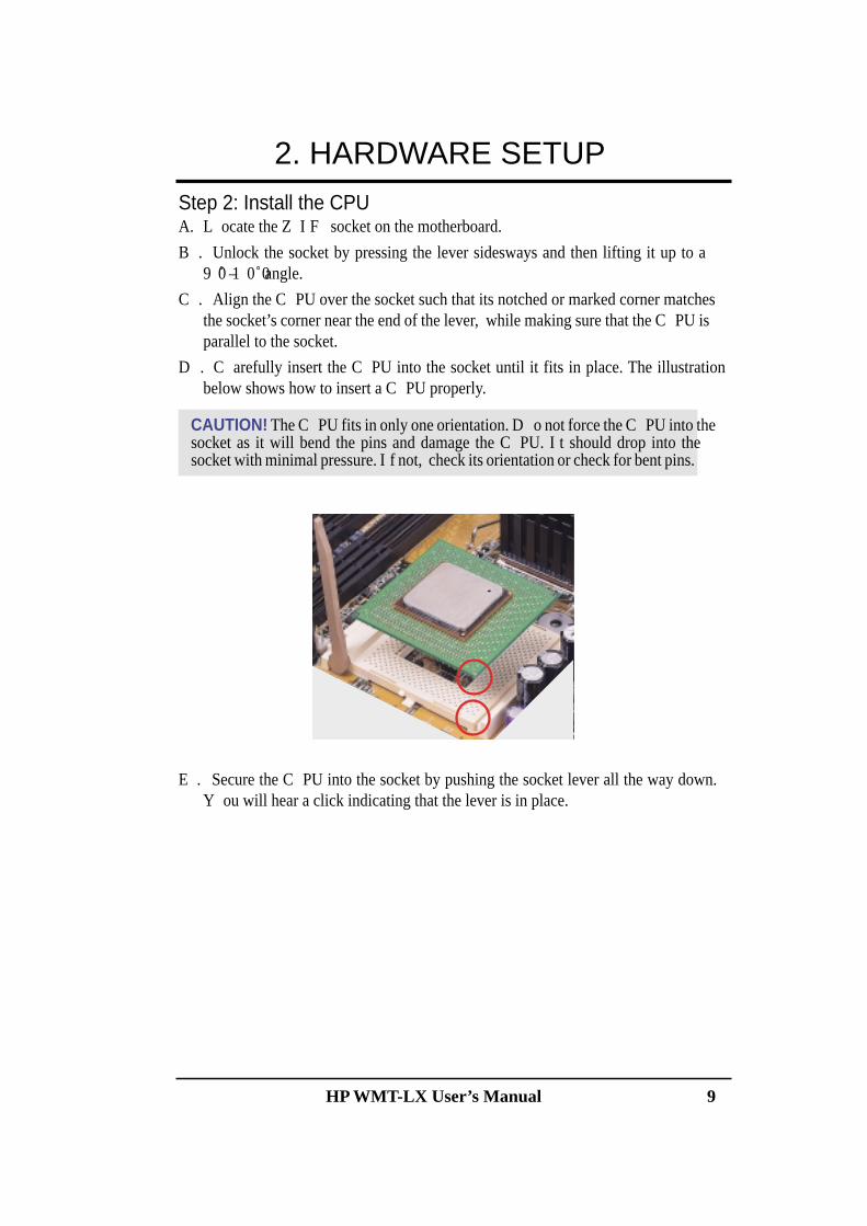
Step 2: Install the CPUA. L ocate the Z I F socket on the motherboard.
B . Unlock the socket by pressing the lever sidesways and then lifting it up to a9 0̊ –1 0 0˚ angle.
C . Align the C PU over the socket such that its notched or marked corner matchesthe socket’s corner near the end of the lever, while making sure that the C PU isparallel to the socket.
D . C arefully insert the C PU into the socket until it fits in place. The illustrationbelow shows how to insert a C PU properly.
CAUTION! The C PU fits in only one orientation. D o not force the C PU into thesocket as it will bend the pins and damage the C PU. I t should drop into thesocket with minimal pressure. I f not, check its orientation or check for bent pins.
E . Secure the C PU into the socket by pushing the socket lever all the way down.Y ou will hear a click indicating that the lever is in place.
10 HP WMT-LX User’s Manual
2. HARDWARE SETUP
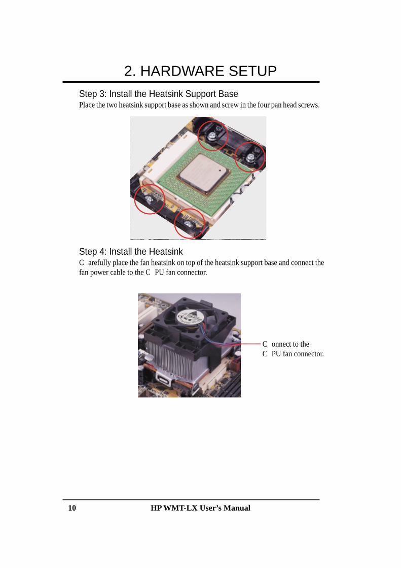
Step 3: Install the Heatsink Support BasePlace the two heatsink support base as shown and screw in the four pan head screws.
Step 4: Install the HeatsinkC arefully place the fan heatsink on top of the heatsink support base and connect thefan power cable to the C PU fan connector.
C onnect to theC PU fan connector.
HP WMT-LX Manual 11
2. HARDWARE SETUP2.4 Expansion Cards
WARNING! Unplug your power supply when adding or removing expansioncards or other system components. Failure to do so may cause severe damage toboth your motherboard and expansion cards (see 3.3 Hardware Setup Proce-dure for more information).
2.4.1 Expansion Card Installation Procedure1. Read the documentation for your expansion card and make any necessary hard-
ware or software settings for your expansion card, such as jumpers.2. Remove your computer system’s cover and the bracket plate on the slot you
intend to use. Keep the bracket for possible future use.3. Carefully align the card’s connectors and press firmly.4. Secure the card on the slot with the screw you removed above.5. Replace the computer system’s cover.6. Set up the BIOS if necessary
(such as IRQ xx Used By ISA: Yes in PNP AND PCI SETUP)7. Install the necessary software drivers for your expansion card.
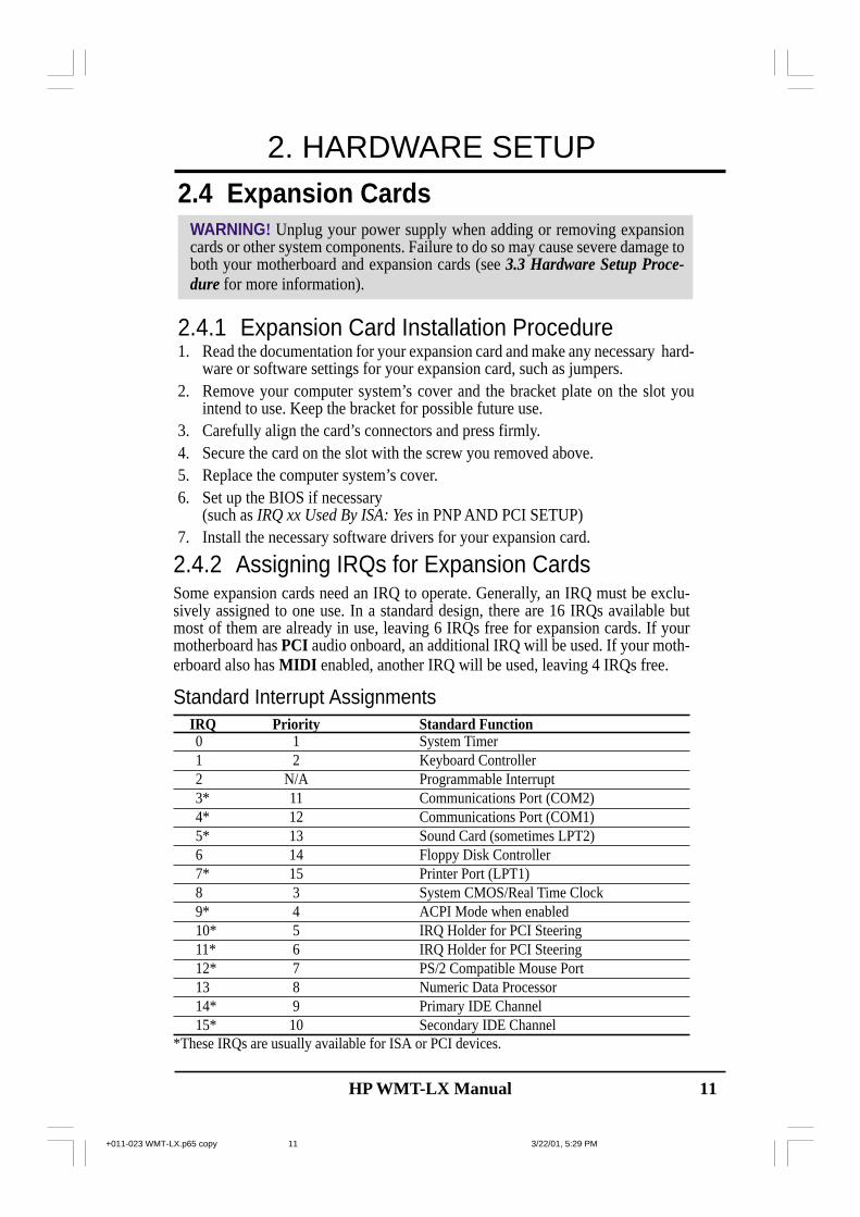
2.4.2 Assigning IRQs for Expansion CardsSome expansion cards need an IRQ to operate. Generally, an IRQ must be exclu-sively assigned to one use. In a standard design, there are 16 IRQs available butmost of them are already in use, leaving 6 IRQs free for expansion cards. If yourmotherboard has PCI audio onboard, an additional IRQ will be used. If your moth-erboard also has MIDI enabled, another IRQ will be used, leaving 4 IRQs free.
Standard Interrupt AssignmentsIRQ Priority Standard Function0 1 System Timer1 2 Keyboard Controller2 N/A Programmable Interrupt3* 11 Communications Port (COM2)4* 12 Communications Port (COM1)5* 13 Sound Card (sometimes LPT2)6 14 Floppy Disk Controller7* 15 Printer Port (LPT1)8 3 System CMOS/Real Time Clock9* 4 ACPI Mode when enabled10* 5 IRQ Holder for PCI Steering11* 6 IRQ Holder for PCI Steering12* 7 PS/2 Compatible Mouse Port13 8 Numeric Data Processor14* 9 Primary IDE Channel15* 10 Secondary IDE Channel
*These IRQs are usually available for ISA or PCI devices.
+011-023 WMT-LX.p65 copy 3/22/01, 5:29 PM11

12 HP WMT-LX Manual
2. HARDWARE SETUP
IMPORTANT: If using PCI cards on shared slots, make sure that the drivers sup-port “Share IRQ” or that the cards do not need IRQ assignments. Conflicts will arisebetween the two PCI groups that will make the system unstable or cards inoperable.
2.4.3 Accelerated Graphics Port (AGP) Pro SlotThis motherboard provides an accelerated graphics port (AGP) pro slot to support anew generation of AGP graphics cards with ultra-high memory bandwidth.
WMT-LX Accelerated Graphics Port (AGP)
RJ-45Top:
WMT-LX
CAUTION! The AGP Pro slot is shipped with a warning label over the 20-pin bay.DO NOT remove this label and the safety tab underneath it if you will be using anAGP card without a retention notch. Removing may cause thecard to shift and may cause damage to your card, slot, and moth-erboard. Remove ONLY when you will be using an AGP Procard. Use a rigid tip, such as a pen tip, to dislodge and removethe tab from the bay.
Removing the tab
Interrupt Request Table for this MotherboardINT-A INT-B INT-C INT-D INT-E INT-F INT-G INT-H
PCI slot 1 — — — — — shared — —PCI slot 2 — — — — — — used —PCI slot 3 — — — — — — — sharedAGP slot used — — — — — — —USB HC0 — — — used — — — —USB HC1 — — — — — — — sharedSMB — shared — — — — — —AC’97 — shared — — — — — —LAN (8139C) — — — — — shared — —
+011-023 WMT-LX.p65 copy 3/22/01, 5:29 PM12
HP WMT-LX Manual 13
2.5 External Connectors
WARNING! Some pins are used for connectors or power sources. These areclearly distinguished from jumpers in the Motherboard Layout. Placing jumpercaps over these connector pins will cause damage to your motherboard.
IMPORTANT: Ribbon cables should always be connected with the red stripe toPin 1 on the connectors. Pin 1 is usually on the side closest to the power connec-tor on hard drives and CD-ROM drives, but may be on the opposite side onfloppy disk drives. Check the connectors before installation because there maybe exceptions. IDE ribbon cables must be less than 46 cm (18 in.), with thesecond drive connector no more than 15 cm (6 in.) from the first connector.
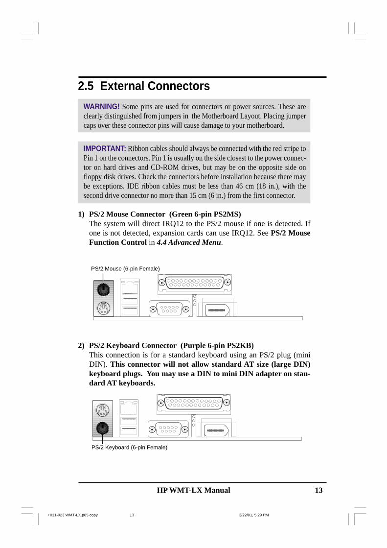
1) PS/2 Mouse Connector (Green 6-pin PS2MS)The system will direct IRQ12 to the PS/2 mouse if one is detected. Ifone is not detected, expansion cards can use IRQ12. See PS/2 MouseFunction Control in 4.4 Advanced Menu.
2) PS/2 Keyboard Connector (Purple 6-pin PS2KB)This connection is for a standard keyboard using an PS/2 plug (miniDIN). This connector will not allow standard AT size (large DIN)keyboard plugs. You may use a DIN to mini DIN adapter on stan-dard AT keyboards.
PS/2 Keyboard (6-pin Female)
PS/2 Mouse (6-pin Female)
+011-023 WMT-LX.p65 copy 3/22/01, 5:29 PM13

14 HP WMT-LX Manual
3) Parallel Port Connector (Burgundy 25-pin PRINTER)You can enable the parallel port and choose the IRQ through OnboardParallel Port (see 4.4.2 I/O Device Configuration).NOTE: Serial printers must be connected to the serial port.
5) IEEE-1394 Controller Interface Connector (6-pin 1394_CON)This connector supports external digital devices.
Serial Port (9-pin Male) COM 1
4) Serial Port Connectors (Teal/Turquoise 9-pin COM1)One serial port is ready for a mouse or other serial devices. A secondserial header is available using a serial port bracket connected from themotherboard to an expansion slot opening. See Onboard Serial Port1/2 in 4.4.2 I/O Device Configuration for settings.
Parallel (Printer) Port (25-pin Female)
IEEE 1394 (6-pin Male)
+011-023 WMT-LX.p65 copy 3/22/01, 5:29 PM14

HP WMT-LX Manual 15
7) Fast-Ethernet Port Connector (RJ45)The RJ45 connector is optional at the time of purchase and is located ontop of the USB connectors. The connector allows the motherboard toconnect to a Local Area Network (LAN) through a network hub.
6) Universal Serial Bus Ports (Black two 4-pin USB)Two USB ports are available for connecting USB devices. For addi-tional USB ports, you can use the USB headers (see USB Headers laterin this section).NOTE: USB Function (see 4.4.3 PCI Configuration) must be Enabledto use these ports.
Universal Serial Bus (USB) 2
USB 1
RJ-45
+011-023 WMT-LX.p65 copy 3/22/01, 5:29 PM15

16 HP WMT-LX Manual
2. HARDWARE SETUP8) Primary (Blue) / Secondary IDE Connectors (Two 40-1pin IDE)
These connectors support the IDE hard disk ribbon cable. Connect thecable’s blue connector to the motherboard’s primary (recommended) orsecondary IDE connector, and then connect the gray connector to yourUltraDMA/100 slave device (hard disk drive) and the black connectorto your UltraDMA/100 master device. It is recommended that non-UltraDMA/100 devices be connected to the secondary IDE connector.If you install two hard disks, you must configure the second drive toSlave mode by setting its jumper accordingly. Please refer to your harddisk documentation for the jumper settings. BIOS now supports specificdevice bootup (see 4.6 Boot Menu). (Pin 20 is removed to preventinserting in the wrong orientation when using ribbon cables withpin 20 plugged).
TIP: You may configure two hard disks to be both Masters with tworibbon cables – one for the primary IDE connector and another for thesecondary IDE connector. You may install one operating system on anIDE drive and another on a SCSI drive and select the boot disk through4.6 Boot Menu.
IMPORTANT: UltraDMA/100 IDE devices must use a 40-pin 80-conductor IDEcable for 100MByte/sec transfer rates.
WMT-LX IDE Connectors
NOTE: Orient the red markings(usually zigzag) on the IDEribbon cable to PIN 1.
Sec
onda
ry ID
E C
onne
ctor
PIN 1
Prim
ary
IDE
Con
nect
or
RJ-45Top:
WMT-LX
+011-023 WMT-LX.p65 copy 3/22/01, 5:29 PM16

HP WMT-LX Manual 17
9) Floppy Disk Drive Connector (34-1pin FLOPPY)This connector supports the provided floppy drive ribbon cable. Afterconnecting the single end to the board, connect the two plugs on theother end to the floppy drives. (Pin 5 is removed to prevent insertingin the wrong orientation when using ribbon cables with pin 5plugged).
10) IEEE-1394 Headers (8-pin 1394HEAD2/1394HEAD3)These headers support an IEEE-1394 serial connector cable set that mountsto a standard expansion slot in the computer case. 1394-compliant inter-nal fixed disk drives may also be connected to these headers.
RJ-45Top:
WMT-LX
WMT-LX IEEE-1394 Headers
1394HEAD2
GroundGroundTPA2+TPA2-
TPB2-TPB2+
Ground+12V
1394HEAD3
+12VGroundTPB3-TPB3+
TPA3+TPA3-
GroundGround
NOTE: Orient the red markings onthe floppy ribbon cable to PIN 1.
WMT-LX Floppy Disk Drive Connector
PIN 1
FLOPPYRJ-45Top:
WMT-LX
+001-023 WMT-LX.p65 copy 3/23/01, 9:32 AM17
18 HP WMT-LX Manual
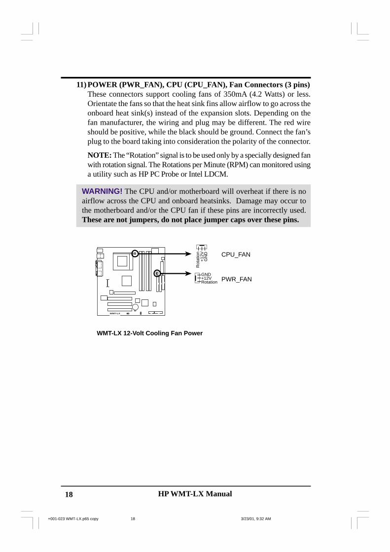
11) POWER (PWR_FAN), CPU (CPU_FAN), Fan Connectors (3 pins)These connectors support cooling fans of 350mA (4.2 Watts) or less.Orientate the fans so that the heat sink fins allow airflow to go across theonboard heat sink(s) instead of the expansion slots. Depending on thefan manufacturer, the wiring and plug may be different. The red wireshould be positive, while the black should be ground. Connect the fan’splug to the board taking into consideration the polarity of the connector.
NOTE: The “Rotation” signal is to be used only by a specially designed fanwith rotation signal. The Rotations per Minute (RPM) can monitored usinga utility such as HP PC Probe or Intel LDCM.
WARNING! The CPU and/or motherboard will overheat if there is noairflow across the CPU and onboard heatsinks. Damage may occur tothe motherboard and/or the CPU fan if these pins are incorrectly used.These are not jumpers, do not place jumper caps over these pins.
RJ-45Top:
WMT-LX
WMT-LX 12-Volt Cooling Fan Power
PWR_FAN
CPU_FAN
GND
Rotation+12V
GN
D
Rot
atio
n+
12V
+001-023 WMT-LX.p65 copy 3/23/01, 9:32 AM18
HP WMT-LX Manual 19
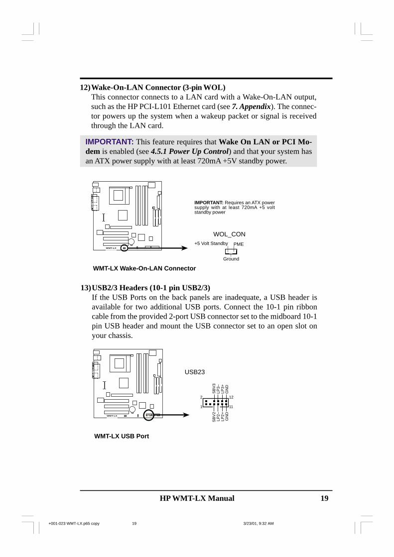
13)USB2/3 Headers (10-1 pin USB2/3)If the USB Ports on the back panels are inadequate, a USB header isavailable for two additional USB ports. Connect the 10-1 pin ribboncable from the provided 2-port USB connector set to the midboard 10-1pin USB header and mount the USB connector set to an open slot onyour chassis.
WMT-LX USB Port
RJ-45Top:
WMT-LX
1
2
11
12
GN
DG
ND
LP2–
LP2+
SB
V2
LP3–
LP3+
SB
V3
USB23
12)Wake-On-LAN Connector (3-pin WOL)This connector connects to a LAN card with a Wake-On-LAN output,such as the HP PCI-L101 Ethernet card (see 7. Appendix). The connec-tor powers up the system when a wakeup packet or signal is receivedthrough the LAN card.
IMPORTANT: This feature requires that Wake On LAN or PCI Mo-dem is enabled (see 4.5.1 Power Up Control) and that your system hasan ATX power supply with at least 720mA +5V standby power.
RJ-45Top:
WMT-LX
WMT-LX Wake-On-LAN Connector
IMPORTANT: Requires an ATX powersupply with at least 720mA +5 voltstandby power
+5 Volt Standby PME
Ground
WOL_CON
+001-023 WMT-LX.p65 copy 3/23/01, 9:32 AM19

20 HP WMT-LX Manual
14)Power Supply Connectors (20-pin block ATXPWR)(6-pin AUXPWR)(4-pin ATX12V)
These connectors connect to an ATX 12V power supply. Each plug fromthe power supply will only insert in one orientation because of the dif-ferent hole sizes. Find the proper orientation and push down firmly mak-ing sure that the pins are aligned. An auxiliary power supply may beneeded depending on your system configuration.
IMPORTANT: Make sure that your ATX 12V power supply (minimumrecommended wattage: 230 watts; 300W for a fully-configured system)can supply at least 20 amperes on the +5-volt lead and at least 720mA onthe +5-volt standby lead (+5VSB). Your system may become unstable/unreliable and may experience difficulty in powering up if your powersupply is inadequate. For Wake-On-LAN support, your ATX power sup-ply (minimum recommended wattage: 230watts) must supply at least720mA +5VSB.
RJ-45Top:
WMT-LX
WMT-LX ATX &Auxiliary Power Connectors
ATX12V
Pin 1
ATXPWR
+3.3VDC-12.0VDCCOMPS_ON#
COMCOM
COM-5.0VDC+5.0VDC+5.0VDC
PWR_OK
+12.0VDC
+3.3VDC+3.3VDC
COM
+5.0VDCCOM
+5.0VDC
COM
+5VSB
+12V DCCOM
+12V DCCOM
Pin 1
+001-023 WMT-LX.p65 copy 3/23/01, 9:32 AM20

HP WMT-LX Manual 21
WMT-LX System Panel Connectors
RJ-45Top:
WMT-LX
* Requires an ATX power supply.
IDE
LED
-K
eylo
ck
+5V
Spe
aker
SpeakerConnector
Power LED
Gro
und
Reset SW
IDELED
Message LED
Ext
SM
I#
Res
etG
roun
d
Gro
und
Keyboard Lock
ATX PowerSwitch*
PW
RB
TN
Gro
und
IDE
LED
+
PW
RLE
D+
PW
RLE
D-
PW
RLE
DB
-
MS
GLE
D+
MS
GLE
D-
Gro
und
SMI Lead
The following diagram is for items 15–22
15) ATX Power Switch Lead (2 pin PWR)The system power is controlled by a momentary switch connectedto this lead. Pressing the button once will switch the system be-tween ON and SOFT OFF. Pushing the switch while in the “ONmode” for more than 4 seconds turns the system off. The systempower LED shows the status of system power.
16) IDE Activity LED (2 pin IDELED)This connector supplies power to the cabinet’s IDE activity LED.Reading and writing activity by devices connected to the Primary/Secondary IDE causes the LED to light up.
17) System Power LED Lead (3-1 pin PLED)This 3-1 pin connector supplies the system power LED, which lightswhen the system is powered on and blinks in sleep or soft-off mode.
18) Reset Switch Lead (2 pin RESET)This 2 pin connector powers the case-mounted reset switch forrebooting without having to turn off the power switch. Use thereset switch to prolong the life of the power supply.
19) System Message LED Lead (2 pin MLED)This LED indicates an incoming of message from a fax/modem.The LED will remain lit when there is no signal and blink whendata is received. This LED requires an ACPI OS and a driver.
20) Keyboard Lock Switch Lead (2 pin KEYLOCK)This 2-pin connector connects to the case-mounted key switch toallow keyboard locking.
21) System Management Interrupt Switch Lead (2 pin SMI)This is a system power switch that allows the user to put thesysteminto suspension to save electricity and prolong the life ofcertain components. The connector supports a 2 pin case-mountedswitch.
22) System Warning Speaker Connector (4 pin SPEAKER)This 4-pin connector supplies the case-mounted speaker. Twosources (LINE_OUT and SPEAKER) support system beeps andwarnings. Only this SPEAKER connector supports system beepsbefore the integrated audio has been properly initialized.
+001-023 WMT-LX.p65 copy 3/23/01, 9:32 AM21

22 HP WMT-LX Manual
23) Erasing the CMOS Real Time Clock (RTC) RAM
A Note about PasswordsBIOS Setup programs allow you to specify passwords in the Main menu.The passwords control access to the BIOS during system startup. Thepasswords are not case sensitive. The BIOS Setup program allows youto specify two separate passwords: a Supervisor password and a Userpassword. When disabled, anyone may access all BIOS Setup programfunctions. When enabled, the Supervisor password is required for enteringthe BIOS Setup program and having full access to all configuration fields.
Forgot the Password?If you forgot the password, you can clear the password by erasing the CMOSReal Time Clock (RTC) RAM. The RAM data containing the passwordinformation is powered by the onboard button cell battery. To erase the RTCRAM: (1) Unplug your computer, (2) Move jumpers from Normal [2-3] toClear CMOS [1-2], then immediately return the jumper cap to the Normalposition [2-3], (3) Turn ON your computer, (4) Hold down <Delete> duringbootup and enter BIOS setup to re-enter user preferences.
RJ-45Top:
WMT-LX
WMT-LX Clear RTC RAM
CLRTC
NormalClear CMOS
1
2 23
+001-023 WMT-LX.p65 copy 3/23/01, 9:32 AM22