Embed Size (px)
Citation preview
Author: Dr. Alex Arrillaga
Pau, France, 17th Dec 2014
BIOSOURCE-COMP
DESIGN, MANUFACTURING AND
CHARACTERIZATION OF POLYMER
COMPOSITES DERIVED FROM
BIODEGRADABLE RESOURCES, FOR THE USE
IN AUTOMOTIVE STRUCTURAL APPLICATIONS

Project CONSORTIUM;
Contact details of the partners
Project Leader;
Lea Artibai Ikastetxea S.Coop.
Dr. Alex Arrillaga; [email protected]; +(34)94 616 9171
www.leartiker.com
Dr. Gonzalo Guerrica-echevarria; [email protected]; +(34)943 015 443
www.ehu.es
Dr. Ahmed Allal; [email protected] ; +(33) 5 59 40 77 03
http://iprem-ecp.univ-pau.fr/live/
Claire Lacquet-Lassus; [email protected] ; +(33) 5 59 30 37 38
www.apesa.fr

To develop and produce polymeric composites produced from natural sources, and use
these materials to manufacture automotive structural parts, substituting traditional
polymer composites derived from fossil (oil) resources
Specific objetives are:
� Define and characterize the properties of the polymer composites used today for similar purposes
� Select the most suitable automotive structural parts to be developed on the new biocomposite materials
� Develop the biocomposite formulations on lab scale
� Test and validate the biocomposite formulations on industrial scale manufacturing process
� Develop new applications for the automotive industry
� Evaluate the recyclability/biodegradation ratios of the developed formulations
� Disseminate project results and promote the use of the developed biocomposites in other products/aplliactions
Project Objetives

Contextualization of the project (1/3)
Automotive industry has an important role on the Spain-France border area, generating
an important contribution to the economical activity both in terms of production and
employment
Indicators Spain France
Production 45.000,00 189.000,00
Employment 162.000 283.000
European Ranking
3º 1º
1 million of euros
Source: French Comité of car Manufacturers (2011 year)
Industry challenges
� Enhance energy efficiency
� Develop alternative energy
sources
� Reduction of environmental
pressure
� Reduce dependence of
today raw materials (mostly
derived from oil)
Economic data of automotive industry

Contextualization of the project (2/3)
Polymer composites are day to day materials in automotive industry, associated to the
lightweight strategy
Anyway, today polymer composites are dependant on oil, and their production requires
high energy consumption
Average composition of a car
Possitive issues
� Weight reduction and
comfort enhancement
� Reduction of energy
consumption of the car
Negative issues
� Dependence on the price
variation of oil
� High energy consumption
the process of generation
the polymers from oil
� Environmental pollution1 Volkswagen Sustainability report 2012
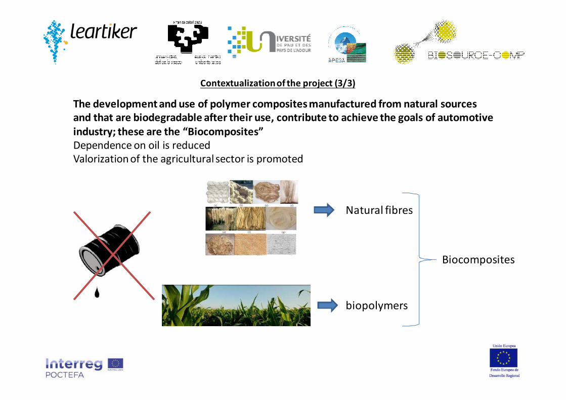
Contextualization of the project (3/3)
The development and use of polymer composites manufactured from natural sources
and that are biodegradable after their use, contribute to achieve the goals of automotive
industry; these are the “Biocomposites”
Dependence on oil is reduced
Valorization of the agricultural sector is promoted
Natural fibres
biopolymers
Biocomposites
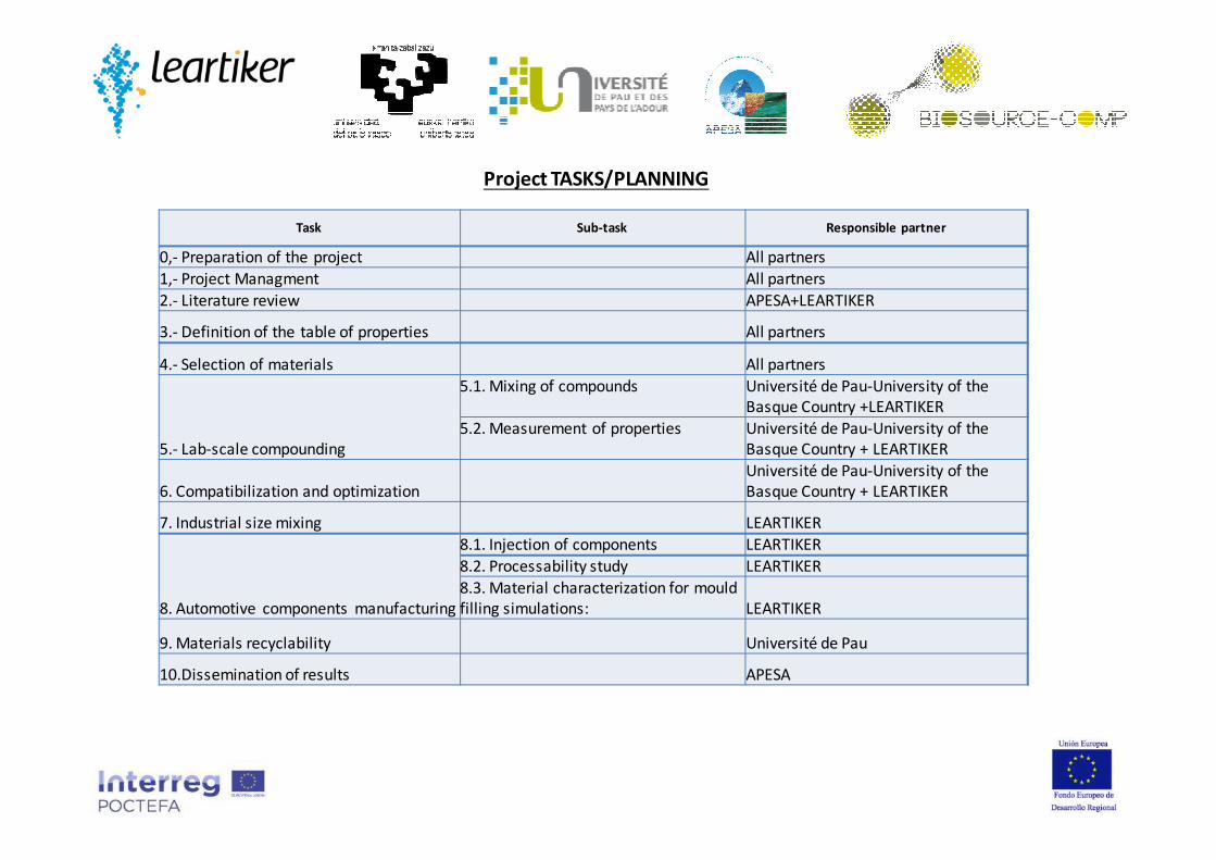
Project TASKS/PLANNING
Task Sub-task Responsible partner
0,- Preparation of the project All partners
1,- Project Managment All partners
2.- Literature review APESA+LEARTIKER
3.- Definition of the table of properties All partners
4.- Selection of materials All partners
5.- Lab-scale compounding
5.1. Mixing of compounds Université de Pau-University of the
Basque Country +LEARTIKER
5.2. Measurement of properties Université de Pau-University of the
Basque Country + LEARTIKER
6. Compatibilization and optimization
Université de Pau-University of the
Basque Country + LEARTIKER
7. Industrial size mixing LEARTIKER
8. Automotive components manufacturing
8.1. Injection of components LEARTIKER
8.2. Processability study LEARTIKER
8.3. Material characterization for mould
filling simulations: LEARTIKER
9. Materials recyclability Université de Pau
10.Dissemination of results APESA

TASK 2; Literature review
bioPE, bioPP, bioPET, bioPA
BIOPLASTICS
PLA, PHA, TPS
Conventional(PE, PS, PP,
PET)
PCL, PBS,PBAT
BiodegradableNON biodegradable
Biobasedmaterial
Petrochemicals
Definition of “Bioplastics”
Source: European bioplastics
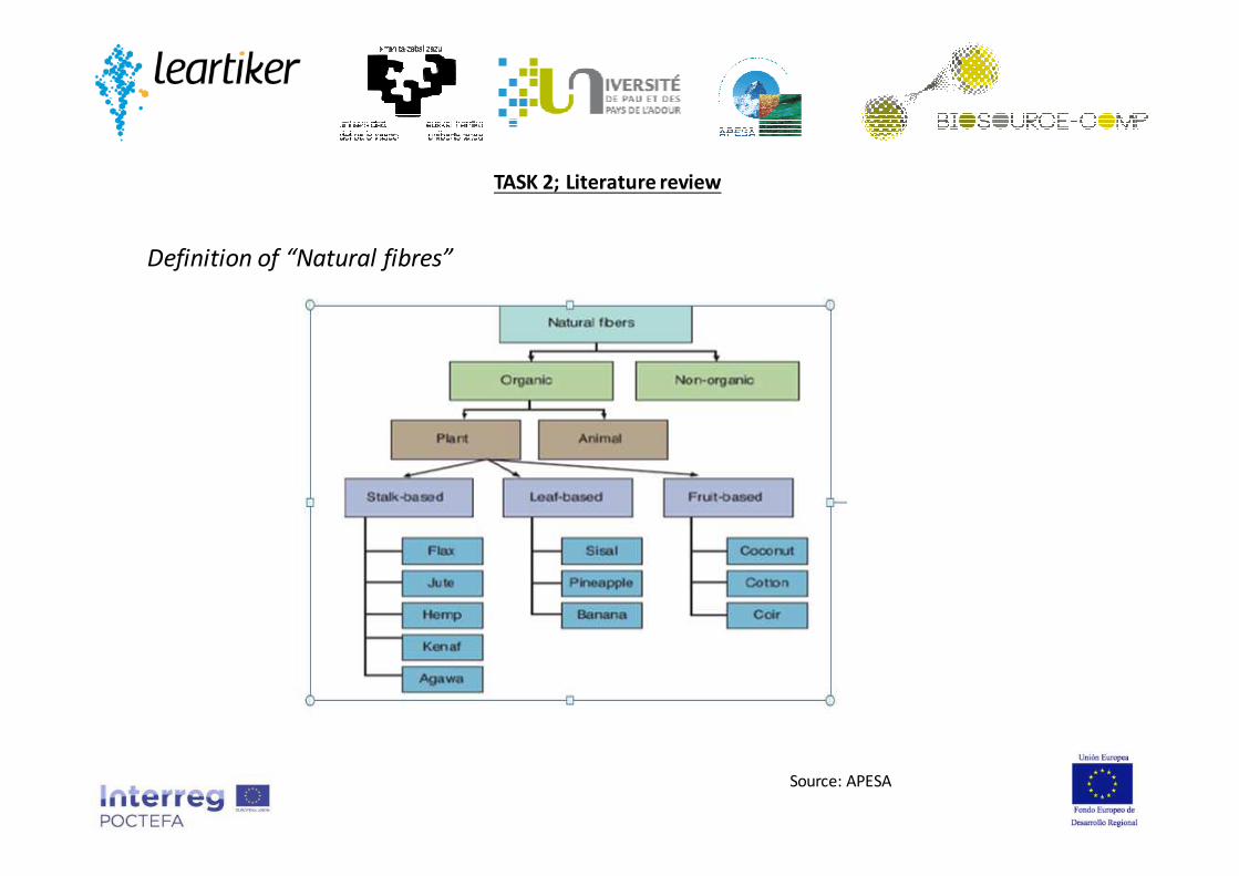
Definition of “Natural fibres”
TASK 2; Literature review
Source: APESA
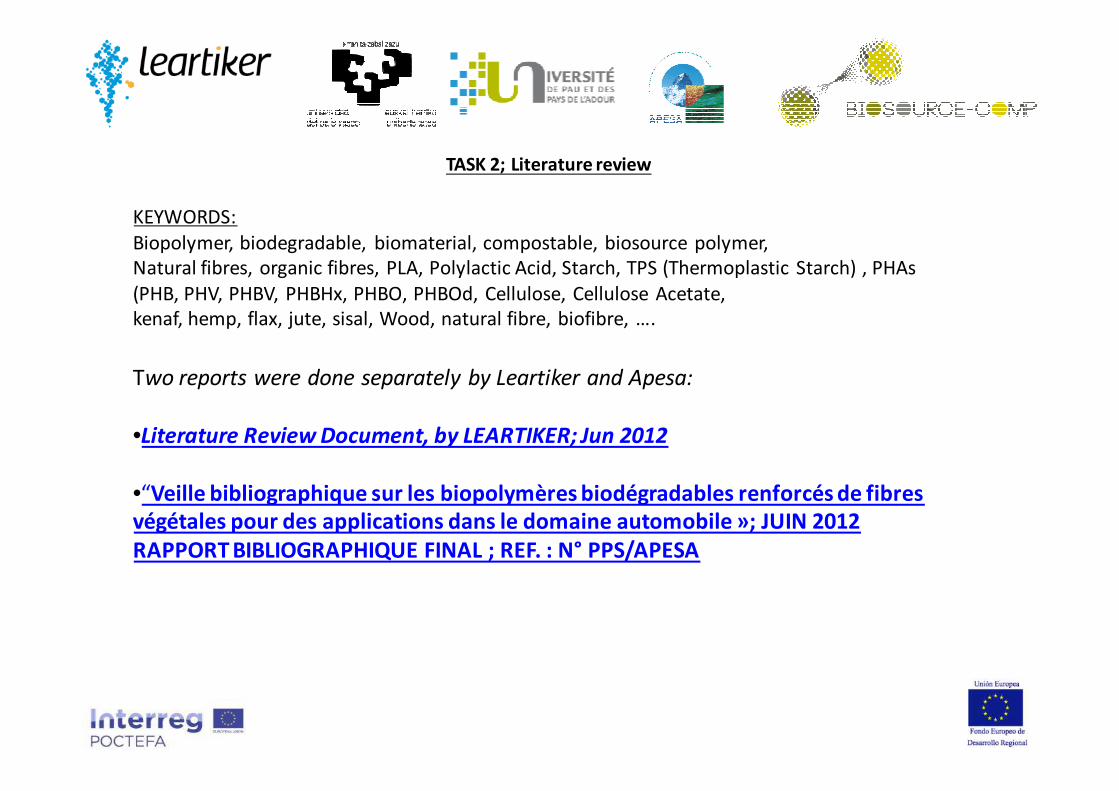
KEYWORDS:
Biopolymer, biodegradable, biomaterial, compostable, biosource polymer,
Natural fibres, organic fibres, PLA, Polylactic Acid, Starch, TPS (Thermoplastic Starch) , PHAs
(PHB, PHV, PHBV, PHBHx, PHBO, PHBOd, Cellulose, Cellulose Acetate,
kenaf, hemp, flax, jute, sisal, Wood, natural fibre, biofibre, ….
Two reports were done separately by Leartiker and Apesa:
•Literature Review Document, by LEARTIKER; Jun 2012
•“Veille bibliographique sur les biopolymères biodégradables renforcés de fibres
végétales pour des applications dans le domaine automobile »; JUIN 2012
RAPPORT BIBLIOGRAPHIQUE FINAL ; REF. : N° PPS/APESA
TASK 2; Literature review

TASK 3; Definition of the technical properties
of polymers used in Automotive Industry.
Individual reports were prepared by Leartiker, EHU and UPPA;
UPPA; COMPOSITES FIBRES VEGETALES VF.pdf
LEARTIKER; BIOSOURCECOMP-Definición de las propiedades y aplicaciones de los polímeros
empleados en automoción LEARTIKER.pdf
EHU: Report of UPV.pdf

Door module (carrier)
High Thermal
and
Mechanical
requirements Battery box
Front end carrier
Track control arm (LINKS); Gearshift Linkage
TASK 3; Definition of the technical properties
of polymers used in Automotive Industry.
Pre-selected components were:

Medium
Mechanical
requirements
Hatchback doors Floor covering panels
Dashboard
Spare Wheel Well Parking BrakesPedal boxes
TASK 3; Definition of the technical properties
of polymers used in Automotive Industry.
Pre-selected components were:

Floor covering panels Pedal boxesTrack control arm
(LINKS); Gearshift Linkage
-Big parts, big moulds and
machines
-Exposure to environment
(humidity)
-High properties (alternative to
PA+50-60%GF)
-Critical part Selected module!!!
Preliminary selection of parts-Components
TASK 3; Definition of the technical properties
of polymers used in Automotive Industry.

General considerations:
Use Tº: From -40°C to +80°C.
Brake pedal
It is the pedal with the highest technical specifications, so there are just only very few developments based on
polymer composites.
Maximum deflection of 15 mm with a force of 2700 N
General recomendación: E> 14000 Mpa; σ>211 MPa
Lanxess developed an hybrid insert + overmoulded part. Insert can be metalic or thermoformed PA+47 % Glass
sheet, and the overmoulded material is Durethan® BKV 30 H2.0. Trelleborg Automotive has a similar development
with a metall ic insert.
Clutch pedal
It is the pedal with intermediate specifications.
Maximum deflection of 20 mm with a force of 1000 N
General recomendación: E> 9000 Mpa; σ>136 MPa
Developments done with Ticona’s PA6,6 with 30% glass fiber (σ=135 MPa). Volkswagen produces also these pedals
using Ticona’s PP with 40% Glass fiber (E:8500 Mpa; σ: 110 Mpa and Charpy impact strength at 23 °C: 52 kJ/m2)
Pedal module
TASK 3; Definition of the technical properties
of polymers used in Automotive Industry.
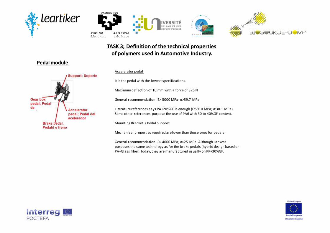
Accelerator pedal
It is the pedal with the lowest specifications.
Maximum deflection of 10 mm with a force of 375 N
General recommendation: E> 5000 MPa; σ>59.7 MPa
Literature references says PA+20%GF is enough (E:5910 MPa; σ:38.1 MPa).
Some other references purpose the use of PA6 with 30 to 40%GF content.
Mounting Bracket / Pedal Support
Mechanical properties required are lower than those ones for pedals.
General recommendation: E> 4000 MPa; σ>25 MPa; Although Lanxess
purposes the same technology as for the brake pedals (hybrid design based on
PA+Glass fiber), today, they are manufactured usually on PP+30%GF.
Pedal module
TASK 3; Definition of the technical properties
of polymers used in Automotive Industry.

A meeting was done between LEARTIKER and Batz S.Coop. company.
Batz S.Coop. purposed to develop an alternative material for the Clutch pedal.
Example of the Clutch pedal + its support manufactured by Batz S.Coop. for VW Polo model:
Clutch Pedal on: PA+40%GF.
Support or brake on: PP+30%GF;
Selection of the final component
As a result, clutch pedal was selected as the part to be developed on the present project
TASK 3; Definition of the technical properties
of polymers used in Automotive Industry.

Tensile modulus 23ºC: > 8000 MPa
Tensile strength (break) 23ºC: > 100 MPa
Tensile elongation (break) 23ºC: > 3 %
Tensile modulus -20ºC: > 8000 MPa
Tensile strength (break) -20ºC: > 100 MPa
Tensile modulus -60ºC: > 6500 MPa
Tensile strength (break): > -60ºC
Flexural modulus 23ºC: > 5000 MPa
Flexural strength 23ºC: >100 MPa
HDT (1.80 MPa): > 90ºC
Vicat Softening Tº B(50N): > 80ºC
Use temperature range: - 40 to 60ºC.
Charpy impact strength, unnotched (+23°C): > 40
Charpy impact strength, unnotched (-20°C): > 40
Charpy impact strength, notched (+23°C): > 20
Charpy impact strength, notched (-20°C): > 20
Melt flow rate, under 2.16 kg, at inj. tem. Range: > 5 gr/10min
Density: < 1.5 gr/cm3
General
requirements for
the Clutch pedal
*Collapse load > 2000N.
*Stiffness:
-Frontal load of 900 N can lead to a maximum
deformation of 25 mm.
-Side load of 200 N can lead to a maximum
deformation of 30 mm.
*Durability: Dynamic loads in the range -40ºC to 80ºC
* Annealing: not defined yet.
* Other: Resistance to solvents, etc, not defined yet.
Selection of the final component; Mechanical and thermal requirements to be fulfilled by the biocomposite
TASK 3; Definition of the technical properties
of polymers used in Automotive Industry.

TASK 4; Material selection.
Considering part specifications, and various factors such as availability, price, and performance of
different biopolymers and natural fibres:
- PLA was selected as suitable matrix
- Hemp and Flax fibres as reinforcing
Selection of PLA
Two PLAs were acquired, of different “D-lactide” content:
- 3052D; Medium “D” content
-6201D; Low “D” content
Short flax
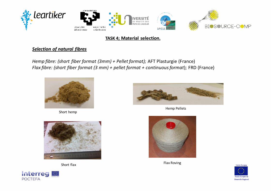
Selection of natural fibres
Hemp fibre: (short fiber format (3mm) + Pellet format); AFT Plasturgie (France)
Flax fibre: (short fiber format (3 mm) + pellet format + continuous format); FRD (France)
TASK 4; Material selection.
Short hempHemp Pellets
Flax Roving

TASK 5; Lab scale Compounding
PLA polymer and the compact fibre pellets were initially dry blended, dropped into the extruder
hopper, and fed into the extruder. Material was processed at a average temperature of 180ºC,
cooled into a conventional water bath and then pelletized.
Formulations of PLA 6201D and 3052D with 10, 20, 30, 40 and 50 Flax and Hemp were
manufactured. Then, samples were injection moulded (to 2 and 4 mm samples)
Initial compounding trials were done using “Procedure A” (EHU procedure).
It was not possible to feed properly “short format fibres” into the extruder, so Compact
fibre pellets were used.
Collin twin screw extruder from EHU was used. Collin ZK25 extruder, with L/D=30

TASK 5; Lab scale Compounding, procedure A
DSC Results
No Tg shift when adding fibres
PLA 6201 has higher Tm than PLA 3201 (lower “D” content)
Tc decreases as we incorporate more fibre
Fibres show a nucleating effect a low fractions; Hemp has more nucleating effect than flax, and it is better seen for PLA6201 than for 3052.
When adding more and more flax, cristallinity goes down, whereas for Hemp it goes increasing a l ittle.

TASK 5; Lab scale Compounding, procedure A
DMA Results
Sample PLA 3052 PLA 6201
Tg Tg
PLA 64.3 ± 0.1 64.2 ± 0.1
PLA extruido 64.4 ± 0.2 64.7 ± 0.1
PLA/10% Flax 64.3 ± 0.4 64.0 ± 0.1
PLA/10% Hemp 63.9 ± 0.5 63.6 ± 1.9
PLA/20% Flax 65.6 ± 0.3 66.0 ± 0.6
PLA/20% Hemp 64.5 ± 0.2 65.2 ± 0.1
PLA/30% Flax 65.1 ± 0.1 66.4 ± 0.4
PLA/30% Hemp 65.7 ± 0.7 65.9 ± 0.2
PLA/40% Flax 66.9 ± 0.1 67.5 ± 0.6
PLA/40% Hemp 66.3 ± 0.2 65.9 ± 0.2
PLA/50% Flax 67.2 ± 0.9 -
PLA/50% Hemp 67.4 ± 0.3 66.1 ± 0.6
Higher fibre % means higher Tº, but the increase is low
No big differences among the two PLA types
No big differences among the two fibres
Objective: 80ºC
Sample PLA 3052 PLA 6201
T T
PLA 57.8 ± 0.4 60.5 ± 0.3
PLA extruido 58.0 ± 0.5 61.0 ± 0.4
PLA/10% Flax 65.0 ± 1.3 61.7 ± 0.3
PLA/10% Hemp 59.0 ± 0.2 61.9 ± 0.2
PLA/20% Flax 64.1 ± 1.0 65.7 ± 0.4
PLA/20% Hemp 59.9 ± 1.1 62.7 ± 0.3
PLA/30% Flax 67.1 ± 1.7 66.9 ± 0.6
PLA/30% Hemp 60.2 ± 0.4 63.6 ± 0.5
PLA/40% Flax 74.1 ± 2.3 72.0 ± 2.6
PLA/40% Hemp 63.7 ± 1.2 66.7 ± 0.8
PLA/50% Flax 77.1 ± 0.9 -
PLA/50% Hemp 71.6 ± 0.7 72.7 ± 0.6
Higher fibre % means higher Tº, more in case of flax than for Hemp (21ºC vs 12ºC)
PLA 6201 gives higher values than PLA3052 (mainly with hemp, but not with flax)
Vicat Results

TASK 5; Lab scale Compounding, procedure A
HDT A Results
No big changes on HDT with fibre concentration.
Comparing both PLAs, when fibre % is low (bellow 30-40), the 6201
exhibits higher HDT A than 3052 (associated to PLA’s
crystallization), but then not.
Results varies as a function of injection parameters (packaging
pressures); for those samples with high % content it was necessary
to apply a higher packaging pressure, so this can make increase the
HDT A value
PLA 3052 PLA 6201
PLA Comercial 43,05 ± 0,2 49,75 ± 0,07
PLA Extruido 48,8 ± 0 49,65 ± 0,07
PLA +10 % hemp 47,3 ± 0 49,75 ± 0,07
PLA +20 % hemp 47,1 ± 0 48,95 ± 0,07
PLA +30 % hemp 47,4 ± 0 50,5 ± 0,14
PLA +40 % hemp 46,3 ± 0,99 48,45 ± 0,64
PLA +50 % hemp 49,35 ± 0,35 50,15 ± 0,35
PLA +50 % hemp + High packaging
51,65 ± 0,21 51,45 ± 0,07
PLA 3052 PLA 6201
PLA Comercial 43,05 ± 0,2 49,75 ± 0,07
PLA Extruido 48,8 ± 0 49,65 ± 0,07
PLA +10 % flax 44,6 ± 0,57 48,25 ± 0,21
PLA +20 % flax 49 ± 0,85 48,9 ± 0,14
PLA +30 % flax 50 ± 0,14 50,35 ± 0,07
PLA +40 % flax 51,45 ± 0,64 51,10 ± 0,14
PLA +50 % flax 51,95 ± 0,21
PLA 3052 +17,5 % flax (Procedure B UPPA) 47,55 ± 0,49
Objective: 80ºC
TASK 5; Lab scale Compounding, procedure A
Muestra Young´s modulus (MPa) EHU
Young´s modulus(MPa) Leartiker
Yield stress (MPa) EHU Break stress (MPa) Ehu Break stress (MPa) Leartiker
Ductility (%) EHU Ductility (%) Leartiker
PLA 3052 PLA 6201 PLA 3052 PLA 6201 PLA 3052 PLA 6201 PLA 3052 PLA 6201 PLA 3052 PLA 6201 PLA 3052 PLA 6201 PLA 3052 PLA 6201
PLA 3305 ± 57 3396 ± 39 3593±45 3493±152 71.2 ± 0.4 73.7 ± 0. 9 67.8 ± 1.3 70.1 ± 1.2 59,5 ± 0,6 61,5 ± 0,4 2.8 ± 0.1 2.9 ± 0 .1 2,2565 ± 0,1 2,446 ± 0,1
Extruded PLA 3313 ± 30 3368 ± 70 3433±43 3579±75 70.2 ± 0. 6 71.9 ± 0.5 63.4 ± 1.9 66.7 ±1.6 58,7 ± 1,3 61,4 ± 1,6 3.3 ± 0.4 3.0 ± 0.3 2,3655 ± 0,3 2,504 ± 0,2
PLA/10% Flax 4975 ± 283 4826 ± 380 4300±144 4556±78 63.6 ± 0.5 63.4 ± 0.3 61.7 ± 1.1 61.2 ± 0.7 54,6 ± 0,5 54,7 ± 0,43 2.5 ± 0.2 2.5 ± 0.2 3,431 ± 0,3 3,48 ± 0,16
PLA/10% Hemp 3874 ± 166 4684 ± 218 4177±277 4260±58 60.8 ± 0.6 59.4 ± 0.6 59.3 ± 0.9 59.0 ± 0.6 54,9 ± 1,1 54,4 ± 1,5 2.1 ± 0.2 1.7 ± 0.1 1,814 ± 0,09 1,752 ± 0,12
PLA/20% Flax 6361 ± 285 5380 ± 447 5738±104 5387±228 68.5 ± 0.3 67.9 ± 0.4 68.1 ± 0.3 67.7 ± 0.4 59,9 ± 0,72 56,7 ± 4,78 2.0 ± 0.1 2.1 ± 0.1 2,621 ± 0,27 2,306 ± 0,58
PLA/20% Hemp 4402 ± 103 4588 ± 126 4787±100 4806±65 58.8 ± 0.3 58.7 ± 0.7 58.1 ± 0.6 58.6 ± 0.7 50,6 ± 0,4 48,1 ± 2,0 1.7 ± 0.1 1.6 ± 0.1 1,476 ± 0,04 1,468 ± 0,20
PLA/30% Flax 7360 ± 46 7423 ± 301 6988±165 6813±667 72.0 ± 1.1 74.7 ± 0.7 71.5 ± 1.1 74.9 ± 0.8 63,3 ± 0,74 64,3 ± 2,82 1.7 ± 0.1 1.6 ± 0.1 2,399 ± 0,15 1,727 ± 0,43
PLA/30% Hemp 5639 ± 197 5632 ± 177 5662±86 5338±405 60.9 ± 0.5 62.3 ± 0.9 60.6 ± 0.7 62.3 ± 0.8 51,9 ± 0,8 50,6 ± 1,7 1.5 ± 0.1 1.51 ± 0.1 1,205 ± 0,04 1,284 ± 0,11
PLA/40% Flax 9211 ± 149 9061 ± 377 8113±121 7862±156 80.2 ± 1.9 80.0 ± 1.2 80.1 ± 1.8 80.5 ± 1.2 72,4 ± 0,72 72,2 ± 0,97 1.3 ± 0.1 1.3 ± 0.1 1,81 ± 0,15 1,53 ± 0,09
PLA/40% Hemp 6484 ± 52 6812 ±3030)
6547±310 6578±290 66.0 ± 1.0 64.4 ± 1.2 65.7 ± 1.0 64.4 ± 1. 1 54,3 ± 1,0 52,8 ± 1,6 1.4 ± 0.1 1.3 ± 0.1 1,206 ± 0,05 1,223 ± 0,13
PLA/50% Flax 8915 ± 303 - 8420±220 - 79.3 ± 2.9 - 79.3 ± 2.9 - 70,5 ± 1,33 ± 1.3 ± 0.1 - 1,369 ± 0,13 ±
PLA/50% Hemp 7352 ± 145 7658 ± 356 7834±292 7351±335 69.2 ± 0.7 65.4 ± 1.6 69.0 ± 0.8 65.5 ± 1.5 57,3 ± 1,4 54,6 ± 1,6 1. 3 ± 0.1 1.3 ± 0.1 1,068 ± 0,11 1,069 ±0,09
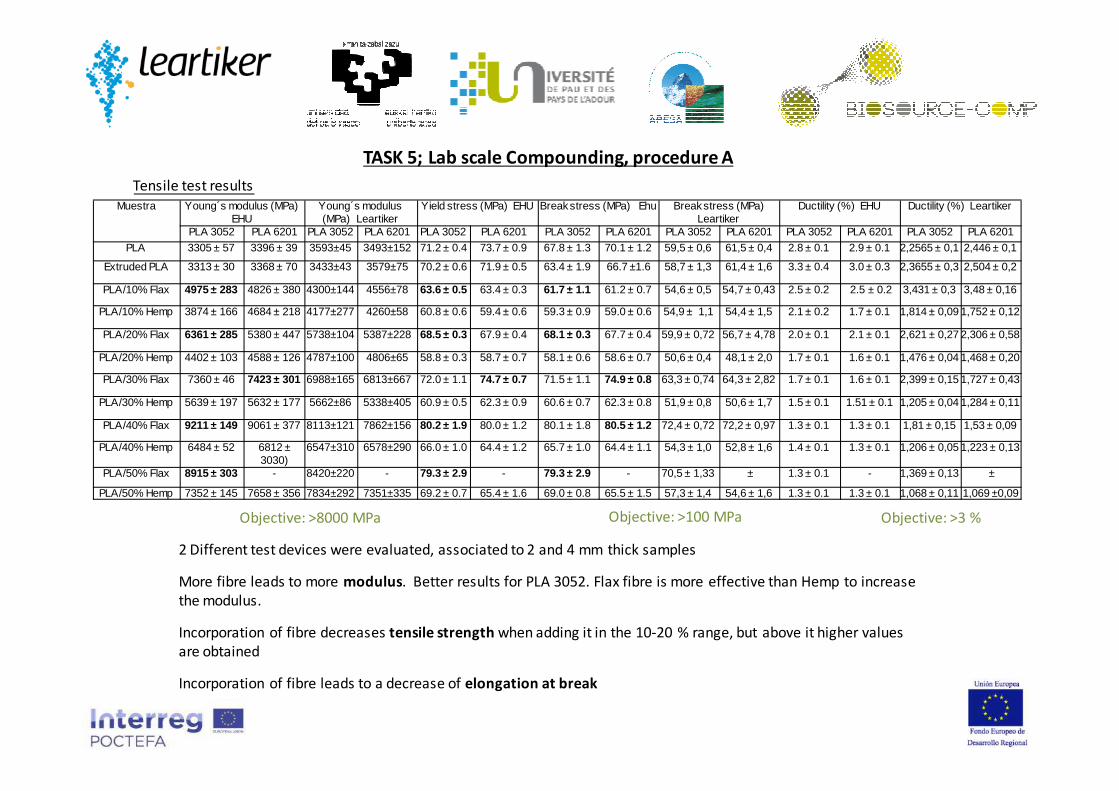
2 Different test devices were evaluated, associated to 2 and 4 mm thick samples
More fibre leads to more modulus. Better results for PLA 3052. Flax fibre is more effective than Hemp to increase
the modulus.
Incorporation of fibre decreases tensile strength when adding it in the 10-20 % range, but above it higher values
are obtained
Incorporation of fibre leads to a decrease of elongation at break
Objective: >8000 MPa Objective: >100 MPa Objective: >3 %
Tensile test results

Sample Notched(J/m) Unnoched (J/m)
PLA 3052 PLA 6201 PLA 3052 PLA 6201
PLA 21.8 ± 5.0 25.1 ± 0.1 207.2 ± 5.2 218.4 ± 13.1
PLA extruido 20.3 ± 6.02.57± 0.5 KJ/m2 *
25.1 ± 0.1 210.2 ± 12.114± 4.46 KJ/m2 *
222.2 ± 11.9
PLA/10% Flax 50.8 ± 1.1 50.0 ± 1.0 223.1 ± 10.9 204.1 ± 14.2
PLA/10% Hemp 24.0 ± 4.8 26.3 ± 2.7 152.0 ±17.9 147.6 ± 12. 9
PLA/20% Flax 56.4 ± 0.8 61.0 ± 1.1 201.7 ± 6.7 200.3 ± 14.3
PLA/20% Hemp 20.9 ± 1.9 24.5 ± 2.9 149.7 ± 15.3 141.7 ± 11. 4
PLA/30% Flax 50.8 ± 2.3 55.0 ± 1.1 156.6 ± 11.5 165.9 ± 10.8
PLA/30% Hemp 19.4 ± 1.1 22.6 ± 0.3 131.3 ± 3.7 118.5 ± 11.3
PLA/40% Flax 53.0 ± 3.53.15± 0.1 KJ/m2 *
49.3 ± 0.9 157.0 ± 9.817.4± 3.51 KJ/m2*
154.5 ± 10.4
PLA/40% Hemp 19.4 ± 0.11.4± 0.2 KJ/m2*
22.6 ± 1.8 128.6 ± 3.63.31± 1.28 KJ/m2*
129.0 ± 14.0
PLA/50% Flax 50.3 ± 2.7 - 146.2± 8.6 -
PLA/50% Hemp 21.8 ± 2.9 20.7 ± 1.1 135.5 ± 12.5 116.8 ± 10. 8
Objective ISO179;
>20 KJ/m2
Objective ISO179;
>40 KJ/m2
Best results for PLA3052 + Flax system
10
20
30
40
50
60
0 10 20 30 40 50 60
Hem pFlax
Not
ched
imp
act
stre
ngt
h (J
/m)
% F iber
120
140
160
180
200
220
240
0 10 20 30 40 50 60
HempFlax
Un
notc
hed
im
pa
ct s
tre
ng
th (
J/m
)
% Fiber
TASK 5; Lab scale Compounding, procedure A
Impact test results
TASK 5; Lab scale Compounding, procedure A
Summarize of results:
•Poor impact resistance; best value of impact resistance was 3,15 KJ/m2 and 17,4 kJ/m2 for notched and un-notched PLA-
40Flax formulation
• Tensile tests show that stiffness of 9 GPa can be achieved when adding 40 % Flax, but maximum tensile strength is set to
80 MPa
•Thermal resistance, measured mainly by HDT A criteria, is very poor.
•Flax fibre is more effective than Hemp
•When incorporating huge quantities of fibre (weight fraction), the purity of PLA does not have influence, so the cheapest
PLA (3052) is preferred.
•PLA 3052 + Flax formulation, on a 60/40 ratio, seems the most suitable formulation to go on

TASK 5; Lab scale Compounding, procedure B
“Procedure B” (UPPA procedure).
It consists on a coating of flax roving by the PLA into a single screw extruder (Haake
Rheomex 252p) Die, and further pelletizing. Because of technical reasons, same
samples of biocomposite were re-extruded in a Labtech LTE 16-40 Twin Screw
extruder.
Samples were injection moulded (to 4 mm thick samples)
Initial injection trials with PLA + 17,5 and 35 Flax content were bad (it was not possible to use
more fibre content, due to a bad coating of the fibres and the bad pelletizing) , as there was
not a uniform material feeding associated to long pellets. PLA and flax fibre need to be well-
dried to avoid bubbles on the surface of the enducted fibre. PLA doesn’t enter the fibre but
stays at its surface (microscopy). Then formulations with 10/20/30 flax pellets were prepared,
with reduced pellet size; Still problems with those formulations with > 20 % fibre content, so
formulations were re-extruded
PLA 3052/ 17.5 FlaxFlax fibre

TASK 5; Lab scale Compounding, procedure B
“Procedure B” (UPPA procedure).
Results are similar to those obtained by Procedure A, that is poor impact resistance and tensile strength. It is confirmed that as fibre
content increases, the stiffness and tensile strength increases, but not the impact resistance.
Additional formulations were done to study the influence of the 2 different PLA degrees and the presence of a plasticizer such as
PEG.
Charpy; Iso 179; 4J Tensile Test MTS Insight ISO 527; 1 mm/minResilience (kJ/m²) Modulus (Mpa) Peak Stress (MPa) Strain at Break (%)
PLA 3052 + 10% FLAX (NO-REEXTRUDED)
2,93 ± 0,225 4292,43 ± 117 57,6 ± 0,74 2,077 ± 0,053
PLA 3052 + 10% FLAX (RE-EXTRUDED)2,85 ± 0,171 3813,5 ± 106 55,1 ± 0,42 2,216 ± 0,08
PLA 3052 + 20% FLAX (RE-EXTRUDED)3,19 ± 0,163 4855,8 ± 144 61,4 ± 0,18 2,48 ± 0,13
PLA 3052 + 30% FLAX (RE-EXTRUDED)3,09 ± 0,223 5266,9 ± 156 62,3 ± 0,59 2,28 ± 0,12

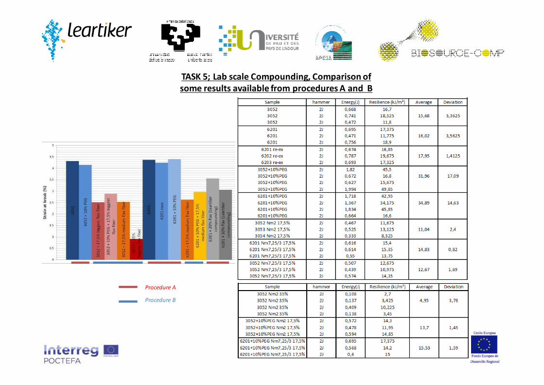
TASK 5; Lab scale Compounding, Comparison of
some results available from procedures A and B
Procedure A
Procedure B
TASK 5; Lab scale Compounding, Comparison of
some results available from procedures A and B
Procedure A
Procedure B

“Procedure C” (Leartiker procedure), is defined as the process were there is a direct
feeding of the natural fibre, in roving format
Brabender DSE 20/40D twin screw extruder from Leartiker was used. L/D=40
PLA polymer was feed at the initial stage of the extruder by a gravimetric feeder (DDW-
MD2-DSR28-10), and the natural fibber roving was fed into the last lateral side entrance.
Material was then cooled into a conventional water bath, and pelletized.
Previous results concluded to focus just on PLA 3052 and Flax fibre
For comparative purposes, a more “pure” fibre was evaluated, that is a “pure” cellulose
fibre, also in roving format. Also, the influence an impact modifier, incorporated at 10 %
was studied.
TASK 5; Lab scale Compounding, procedure C
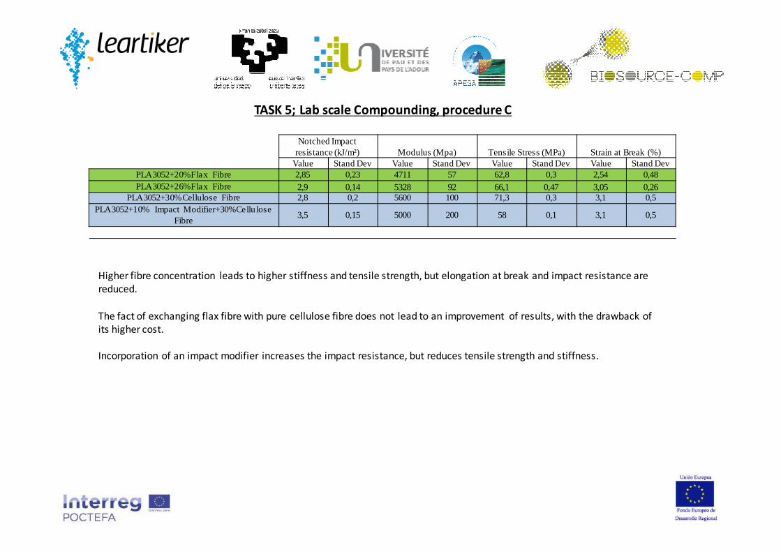
Notched Impact resistance (kJ/m²) Modulus (Mpa) Tensile Stress (MPa) Strain at Break (%)
Value Stand Dev Value Stand Dev Value Stand Dev Value Stand DevPLA3052+20%Flax Fibre 2,85 0,23 4711 57 62,8 0,3 2,54 0,48PLA3052+26%Flax Fibre 2,9 0,14 5328 92 66,1 0,47 3,05 0,26
PLA3052+30%Cellulose Fibre 2,8 0,2 5600 100 71,3 0,3 3,1 0,5PLA3052+10% Impact Modifier+30%Cellu lose
Fibre3,5 0,15 5000 200 58 0,1 3,1 0,5
TASK 5; Lab scale Compounding, procedure C
Higher fibre concentration leads to higher stiffness and tensile strength, but elongation at break and impact resistance are
reduced.
The fact of exchanging flax fibre with pure cellulose fibre does not lead to an improvement of results, with the drawback of
its higher cost.
Incorporation of an impact modifier increases the impact resistance, but reduces tensile strength and stiffness.
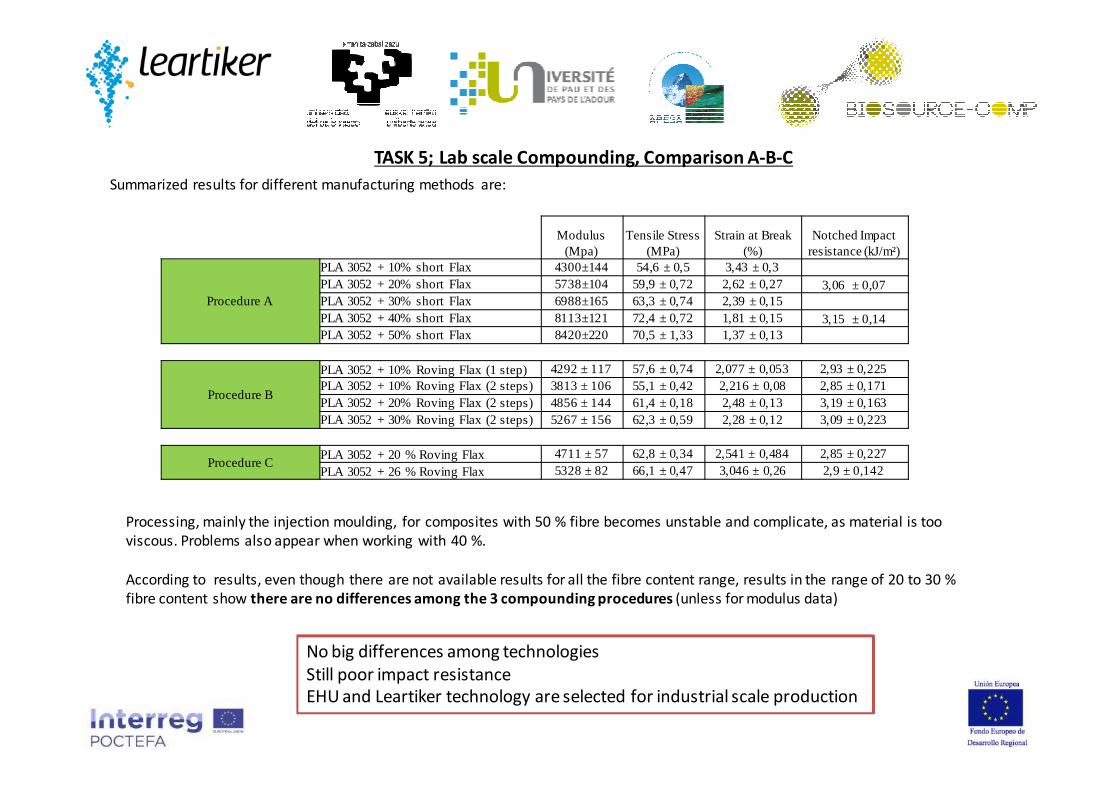
Summarized results for different manufacturing methods are:
TASK 5; Lab scale Compounding, Comparison A-B-C
Modulus (Mpa)
Tensile Stress (MPa)
Strain at Break (%)
Notched Impact resistance (kJ/m²)
Procedure A
PLA 3052 + 10% short Flax 4300±144 54,6 ± 0,5 3,43 ± 0,3PLA 3052 + 20% short Flax 5738±104 59,9 ± 0,72 2,62 ± 0,27 3,06 ± 0,07PLA 3052 + 30% short Flax 6988±165 63,3 ± 0,74 2,39 ± 0,15PLA 3052 + 40% short Flax 8113±121 72,4 ± 0,72 1,81 ± 0,15 3,15 ± 0,14PLA 3052 + 50% short Flax 8420±220 70,5 ± 1,33 1,37 ± 0,13
Procedure B
PLA 3052 + 10% Roving Flax (1 step) 4292 ± 117 57,6 ± 0,74 2,077 ± 0,053 2,93 ± 0,225PLA 3052 + 10% Roving Flax (2 steps) 3813 ± 106 55,1 ±0,42 2,216 ± 0,08 2,85 ± 0,171PLA 3052 + 20% Roving Flax (2 steps) 4856 ± 144 61,4 ±0,18 2,48 ± 0,13 3,19 ± 0,163PLA 3052 + 30% Roving Flax (2 steps) 5267 ± 156 62,3 ±0,59 2,28 ± 0,12 3,09 ± 0,223
Procedure CPLA 3052 + 20 % Roving Flax 4711 ± 57 62,8 ± 0,34 2,541 ± 0,484 2,85 ± 0,227PLA 3052 + 26 % Roving Flax 5328 ± 82 66,1 ± 0,47 3,046 ± 0,26 2,9 ± 0,142
Processing, mainly the injection moulding, for composites with 50 % fibre becomes unstable and complicate, as material is too
viscous. Problems also appear when working with 40 %.
According to results, even though there are not available results for all the fibre content range, results in the range of 20 to 30 %
fibre content show there are no differences among the 3 compounding procedures (unless for modulus data)
No big differences among technologies
Still poor impact resistance
EHU and Leartiker technology are selected for industrial scale production

TASK 5; Lab scale Compounding, Capillary rheometer
35
10
100
1000
100 1000 10000
Vis
cosi
ty(P
a.s
)
Shear Velocity (1/s)
3052 reex 180°
Rabinovitch +
Bagley3052 reex 190°
Rabinovitch +
Bagley3052 30% 180°
R+B
3052 com 190°
Rabinovitch +
Bagley3052 reex 200°
Rabinovitch +
Bagley3052 10% 190°
R+B
3052 50% 180°
R+B
PLA 3052D + Hemp; procedure A; Capillary rheology results
Illogical results : Problems with fibre loaded materials ; high pressure variations due to fibre accumulations in the
1mm die. Solution: fabrication of a 2mm diameter die.

TASK 5; Lab scale Compounding, Parallel plate
rheometer
PLA 3052D and 6201D + Hemp; procedure A; parallel plate results
Uncertainty
zoneUncertainty
zone
Similar behaviour at 190ºC and 200ºC
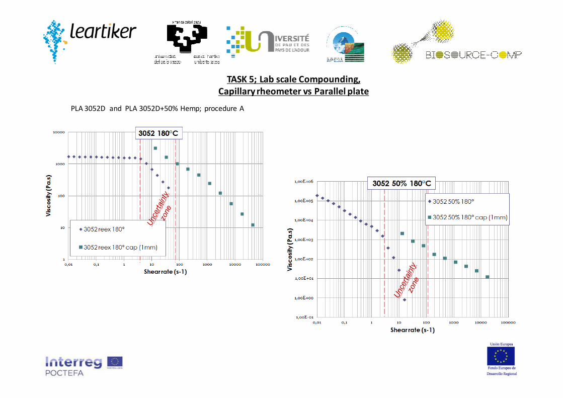
TASK 5; Lab scale Compounding,
Capillary rheometer vs Parallel plate
PLA 3052D and PLA 3052D+50% Hemp; procedure A

TASK 5; Lab scale Compounding,
Capillary rheometer and Parallel plate
PLA + Flax formulations; procedure A and B
Similar behaviour at 190ºC and 200ºC
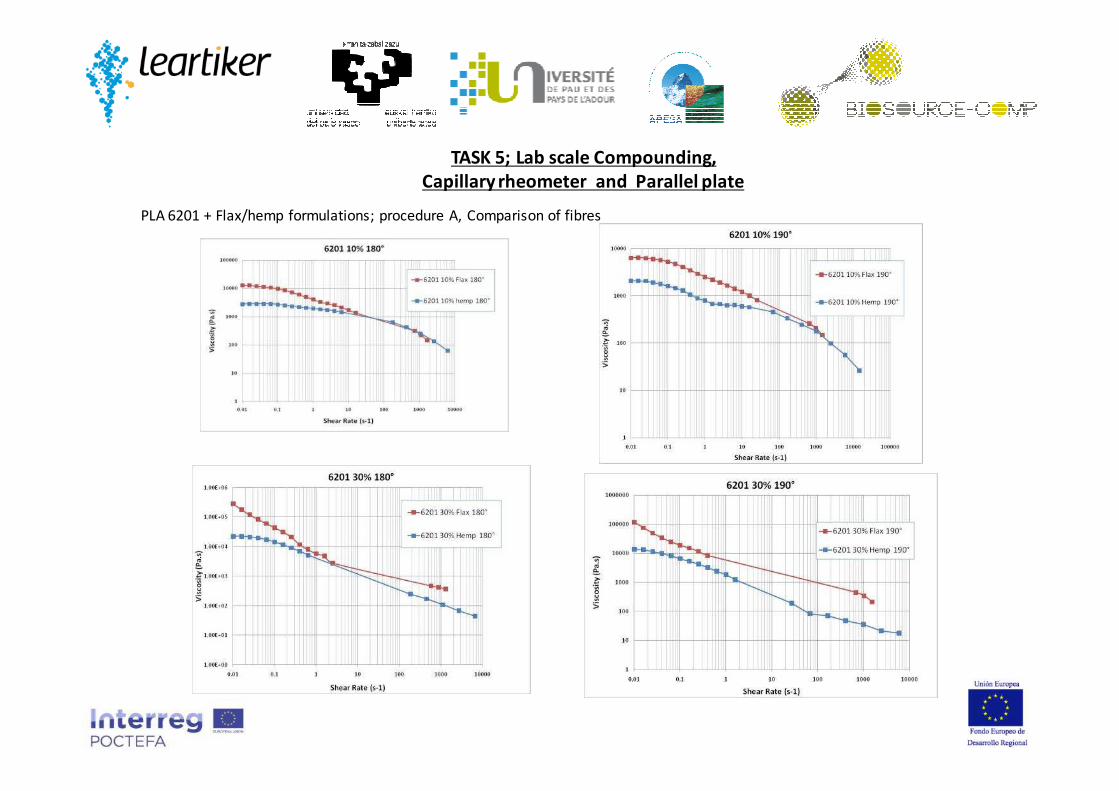
PLA 6201 + Flax/hemp formulations; procedure A, Comparison of fibres
TASK 5; Lab scale Compounding,
Capillary rheometer and Parallel plate

� Disolving in Chloroform
(70°C with agitation, 3h)
� Drying
� Filtration
� Optical microscopy analyses ;
(Zoom 5x)
200 measurements (ImageJ software) for each material :
3052 30% Compacted Flax Compounds
Compounds tested were:
PLA 3052 10,20,30,40% Compacted Flax Compounds, procedure A
PLA 3052 20% Re-extruded Drifted Flax Compound, procedure B
Limitations : biggest and shortest fibers are under-evaluated
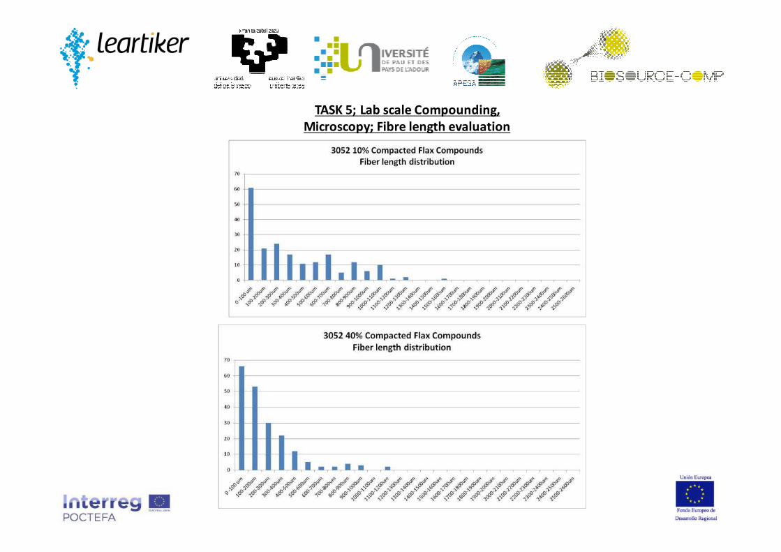
TASK 5; Lab scale Compounding,
Microscopy; Fibre length evaluation
TASK 5; Lab scale Compounding,
Microscopy; Fibre length evaluation

TASK 5; Lab scale Compounding,
Microscopy; Fibre length evaluation
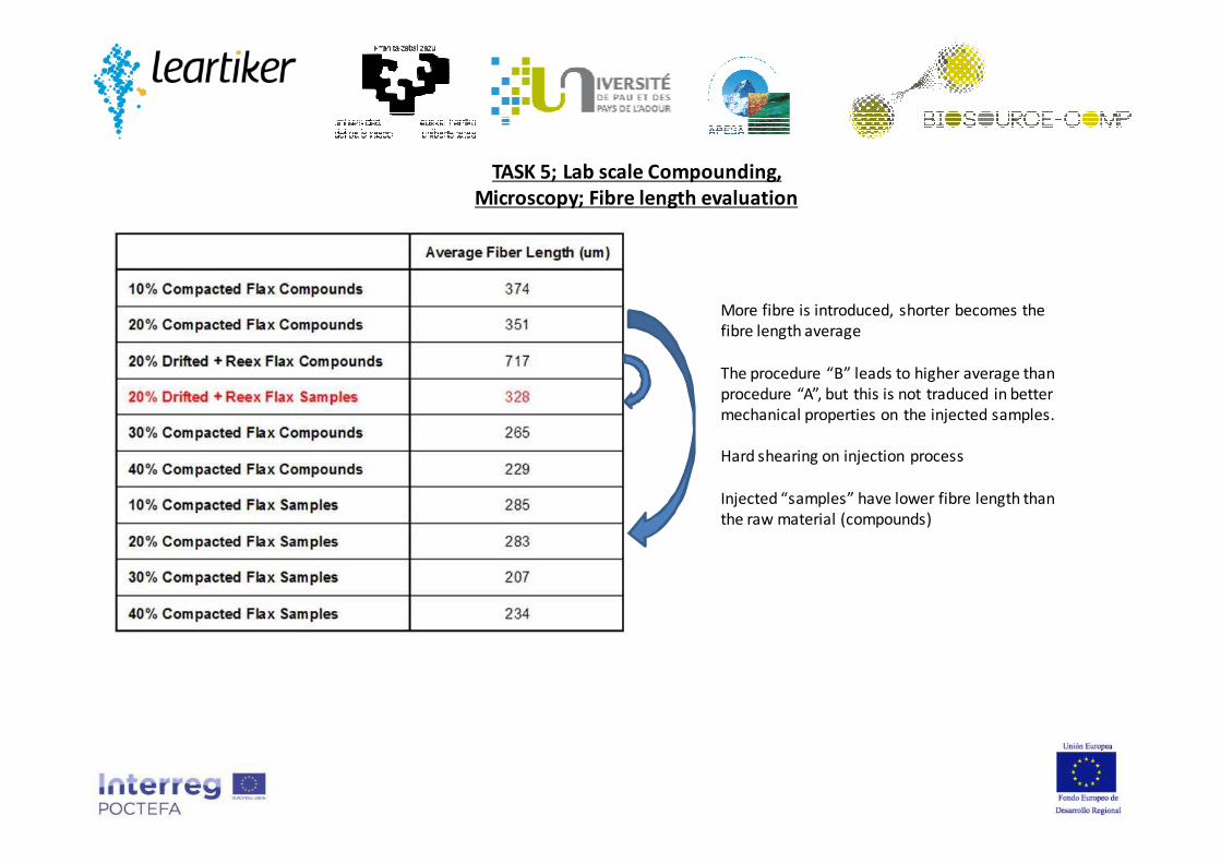
TASK 5; Lab scale Compounding,
Microscopy; Fibre length evaluation
More fibre is introduced, shorter becomes the
fibre length average
The procedure “B” leads to higher average than
procedure “A”, but this is not traduced in better
mechanical properties on the injected samples.
Hard shearing on injection process
Injected “samples” have lower fibre length than
the raw material (compounds)

TASK 6; Compatibilization and optimization,
a) Trial A: the use of a “home-made” PLA-g-Ma (Maleic anhydride grafted PLA)
Manufactured on the twin screw extruder from EHU, maleinizated PLA was manufactured from PLA 3052, at different
concentrations and processing conditions. Then, this PLA-g-Ma was mixed at 60 % content with 40 % Crushed Compact
Flax Pellets (Procedure A) , and extruded and pelletized, for later injection moulding.
tensile test Impact test
Youngsmodulus
(MPa) EHUYoungs modulus(MPa) Leartiker
Yieldstress (MPa) EHU
Break stress (MPa) Ehu
Break stress (MPa)
Leartiker
Elongationat break (%)
EHU
Elongationat break (%) Leartiker
Notched Impactresistance(J/m) EHU
Un-NotchedImpactresistance(J/m) EHU
NotchedImpactresistance(KJ/m2) EHU
Un-NotchedImpactresistance(KJ/m2) EHU
PLA 3052 3305 ± 57 3593 ± 45 71,2 ± 0,4 67,8 ± 1,3 59,5 ± 0,6 2,8 ± 0,1 2,256 ± 0,1 21,8 ± 5,0 207,2 ± 5,2 1,7 ± 0,4 16,6 ± 0,4
PLA 3052 + 40% Flax 9211 ± 149 8113 ± 121 80,2 ± 1,9 80,1 ± 1,8 72,4 ± 0,72 1,3 ±0,1 1,81 ± 0,15 53,0 ± 3,5 157,0 ± 9,8 4,2 ± 0,3 12,6 ± 0,8
PLA 3052 2,5 % Maleinizated + 40% flax 8158 ± 372 7610 ± 131 78,3 ± 1,7 78,3 ± 1,7 66,7 ± 1,72 1,3 ± 0,1 1,33 ± 0,12 18,2 ± 1,2 156,4 ± 18,6 1,8 ± 0,1 12,3 ± 1,5
PLA 3052 5 % Maleinizated + 40% flax 8143 ± 261 7857 ± 79 76,1 ± 1,2 76,0 ± 1,0 64,3 ± 1,06 1,2 ±0,1 1,14 ± 0,04 16,0 ± 2,2 132,9 ± 14,7 1,6 ± 0,2 10,5 ± 1,2
PLA 3052 2 % Maleinizated + 40 % flax; 150 rpm screwspeed
7683 ± 369 6632 ± 773 76,8 ± 2,3 76,7 ± 2,1 67,3 ± 1,77 1,4 ±0,1 1,632 ± 0,148 2,0 ± 0,1 14,1 ± 2,0
PLA 3052 2 % Maleinizated+ 40 % flax; 50 rpm screwspeed
7898 ± 440 6881 ± 232 72,9 ± 3,7 70,7 ± 9,3 67,45 ± 1,14 1,3 ± 0,3 1,8195 ± 0,113 2,1 ± 0,2 11,7 ± 2,3
PLA 6201 + 30 % Flax 7423 ± 301 6813 ± 667 74,7 ± 0,7 74,9 ± 0,8 64,3 ± 2,82 1,6 ±0,1 1,727 ± 0,43 55,0 ± 1,1 165,9 ± 10,8 3,95 ± 0,1 12,4 ± 0,8
PLA 6201 2,5 % Maleinizated+ 30 % Flax, injectedat 170ºC
6920 ± 381 6725 ± 119 65,8 ± 0,4 65,6 ± 0,5 58,2 ± 1,23 1,2 ± 0,1 1,417 ± 0,03 19,7 ± 2,7 119,3 ± 7,6 2,0 ± 0,3 10,4 ± 0,5
PLA 6201 5 % Maleinizated+ 30 % Flax, injectedat170ºC
6465 ± 311 5935 ± 80 63,1 ± 1,2 62,0 ± 2,1 51,5 ± 0,802 1,2 ± 0,1 1,097 ± 0,042 15,4 ± 0,9 131,9 ± 5,9 1,5 ± 0,1 9,4 ± 0,6
PLA 6201 5 % Maleinizated+ 30 % Flax, injectedat 180ºC
6359 ± 313 5917 ± 150 61,1 ± 3,3 60,4 ± 3,1 48,7 ± 0,424 1,1 ± 0,1 1,043 ± 0,049 15,0 ± 0 143,7 ± 9,5 1,5 11,3 ± 0,7
Results show no enhancement of properties.

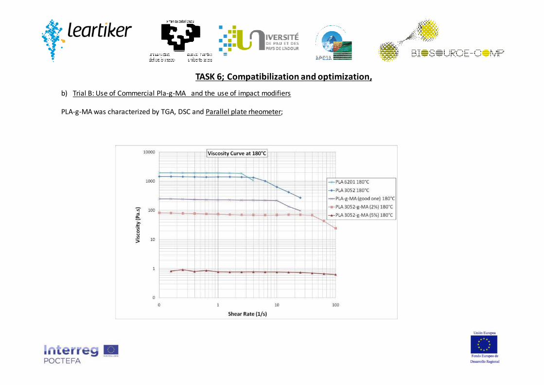
TASK 6; Compatibilization and optimization,
b) Trial B: Use of Commercial Pla-g-Ma and the use of impact modifiers
Maleinization degree (grafting) was of 0.8 %. This material was mixed and extruded with raw PLA 3052 and Flax fiber (roving),
using Leartiker’s compounding procedure (Procedure C). Properties are next:
Presence of PLA-g-Ma gives higher impact resistance, better modulus and better strain. Tensile strength is keep equal. So
technology works!!!! But PLA-g-Ma cost is too high!!!
Incorporation of an impact modifier increases the impact resistance, but reduces tensile strength and stiffness.
PLA-g-Ma was characterized by TGA, DSC and Capillary rheometer.
Notched Impact resistance (kJ/m²) Modulus (Mpa) Tensile Stress (MPa) Strain at Break (%)
Value Stand Dev Value Stand Dev Value Stand Dev Value Stand Dev
PLA3052+20%Flax Fibre 2,85 0,23 4711 57 62,8 0,3 2,54 0,48
PLA3052+30%Cellulose Fibre 2,8 0,2 5600 100 71,3 0,3 3,1 0,5
PLA3052D+PLA-g-MA (90/10) + 20%Flax fibre 3,3 0,1 5100 67 62,7 0,2 3,4 0,8
PLA3052D+PLA-g-MA (90/10) + 30%Cellulose
fibre 3,5 0,2 6000 85 72,4 1,2 2 0,4
PLA3052D+PLA-g-MA (90/10)+Impact modif
(90/10)+ 20%Flax fibre 4,3 0,6 4300 80 50 0,7 5,3 1,1
PLA3052D+PLA-g-MA (90/10)+Impact modif
(80/20)+ 20%Flax fibre 5,9 0,3 4000 120 42 0,4 6 0,7

TASK 6; Compatibilization and optimization,
b) Trial B: Use of Commercial Pla-g-MA and the use of impact modifiers
PLA-g-MA was characterized by TGA, DSC and Parallel plate rheometer
PLA-g-MA
PLA 6201
TASK 6; Compatibilization and optimization,
b) Trial B: Use of Commercial Pla-g-MA and the use of impact modifiers
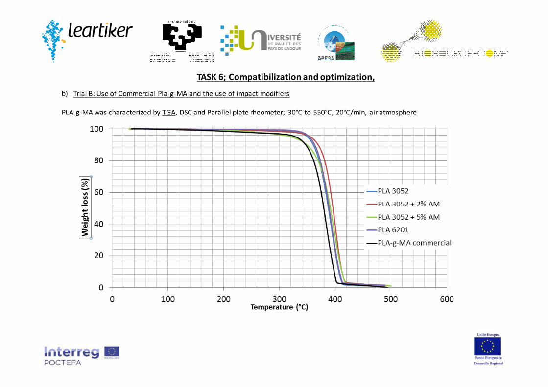
PLA-g-MA was characterized by TGA, DSC and Parallel plate rheometer; 30°C to 550°C, 20°C/min, air atmosphere
TASK 6; Compatibilization and optimization,
b) Trial B: Use of Commercial Pla-g-MA and the use of impact modifiers
PLA-g-MA was characterized by TGA, DSC and Parallel plate rheometer;

TASK 6; Compatibilization and optimization,
c) Trial C: Use of Arkema’s M53 PMMA-PBA copolymer into pure PLA
PLA 6201 / 3052 � Extrusion (190°C) with granulation (1mm)
� Blend with (0 / 2,5 / 5 / 7,5 / 10 / 12,5 / 15 / 20) wt % copolymer (Arkema M53 PMMA-PBA copolymer)
� Extrusion (190°C) with granulation (3mm)
16 Blends were evaluated:
DSC results show the presence of the copolymer reduces PLA’s capability to crystallize; TGA results show thermal stability is
increased when adding the copolymer. Parallel plate rheology tests show the copolymer increases the viscosity of the formulation.
Mechanical tests shows that as much copolymer is added, stiffness and tensile strength are reduced, whereas elongation at
break and impact resistance does not change.
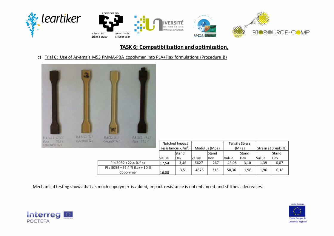
TASK 6; Compatibilization and optimization,
c) Trial C: Use of Arkema’s M53 PMMA-PBA copolymer into PLA+Flax formulations (Procedure B)
Notched Impact
resistance (kJ/m²) Modulus (Mpa)
Tensile Stress
(MPa) Strain at Break (%)
Value
Stand
Dev Value
Stand
Dev Value
Stand
Dev Value
Stand
Dev
Pla 3052 + 22,4 % flax 17,54 3,46 5627 267 43,08 3,10 1,39 0,07
Pla 3052 + 22,4 % flax + 10 %
Copolymer 16,083,51 4676 216 50,36 1,96 1,96 0,18
Mechanical testing shows that as much copolymer is added, impact resistance is not enhanced and stiffness decreases.

TASK 7; Industrial Size mixing,
Industrial scale up was made in Leartiker’s 26 mm twin screw line, with capability to produce polymer compounds at a ratio
of 50 kg/hour (maximum).
Initial set up trials were carried on January 2014, with a 80PLA3052/20 Compacted Flax pellets formulation.
Then, on February 2014, according to Procedure A, formulations of PLA 3052 with 10/20/30 % flax fibre were manufactured.
It was not possible to manufacture formulations with 40 % Flax, because of flow instabilities (to high fibre volume). Melt
flow Tº increases a lot when adding more and more fibre (shearing).
On March/April 2014 , according to Procedure C, formulations of PLA 3052 with 13/15/20,4 and 23,1 % Flax fibre were
manufactured. It was not possible to manufacture with higher fibre content, as there were too much roving's to work with,
and trials based on Procedure A show there was a loose of mechanical performance on such high concentrations. Melt flow
Tº increases a lot when adding more and more fibre (shearing).
Productivity rates were set on 23-25 kg/hour, both working with fibre in pellets or roving format.

Notched Impact
resistance (kJ/m²) Modulus (MPa)
Tensile Stress
(MPa) Strain at Break (%)
Value
Stand
Dev Value
Stand
Dev Value
Stand
Dev Value
Stand
Dev
PLA 3052 +10% Flax Fibre (Procedure
A)2,94 0,1 3200 72 53 0,4 5,1 1,5
PLA 3052 +20% Flax Fibre (Procedure
A)3,2 0,1 4300 55 55 0,6 3 0,2
PLA 3052 +30% Flax Fibre (Procedure
A)3,4 0,1 3200 620 45 7 2,8 0,6
Results show there was a decay in Modulus for the formulation with 30 % fibre, so it is concluded the fibre does not get inside
properly, or there is a fibre damage, as lab scale trials show that as much fibre we introduce higher becomes the modulus.
Screw configuration and fibre feeding (entrance) point were changed in order to “break” less the fibre, but all trials lead to similar
material performance. Conclusion: Even though the compounding procedure is optimized to damage as less as possible the fibre,
the injection moulding process damages definitely the fibre. If the PLA and the fibre are not correctly mixed (too short screw
length), then more processing problems appear (Flow instabilities of the wire to be pelletized).
TASK 7; Industrial Size mixing;
Procedure A Scale up,

TASK 7; Industrial Size mixing;
Procedure C Scale up,
Results are in coherence (same values) with the values obtained in the scale up of the procedure A;
So, there is no criteria to chose Procedure A o C, according to final performance. For a more simple work, procedure A will have more
sense.

TASK 8; Automotive Components manufacturing
Original pedal
According to the original part geometry (courtesy of company Batz S.Coop., and used in the Volkswagen Polo model), a mould
was designed to inject biocomposite samples on it.
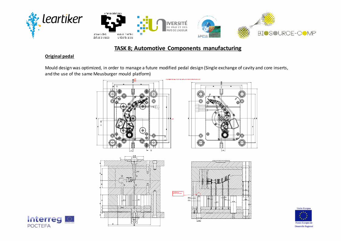
Original pedal
Mould design was optimized, in order to manage a future modified pedal design (Single exchange of cavity and core inserts,
and the use of the same Meusburger mould platform)
TASK 8; Automotive Components manufacturing
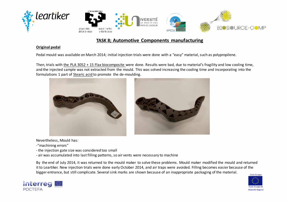
Pedal mould was available on March 2014; initial injection trials were done with a “easy” material, such as polypropilene.
Then, trials with the PLA 3052 + 15 Flax biocomposite were done. Results were bad, due to material’s fragility and low cooling time,
and the injected sample was not extracted from the mould. This was solved increasing the cooling time and incorporating into the
formulations 1 part of Stearic acid to promote the de-moulding.
Nevertheless, Mould has:
-“machining errors”
- the injection gate size was considered too small
- air was accumulated into last filling patterns, so air vents were necessary to machine
By the end of July 2014, it was returned to the mould maker to solve these problems. Mould maker modified the mould and returned
it to Leartiker. New injection trials were done early October 2014, and air traps were avoided. Filling becomes easier because of the
bigger entrance, but still complicate. Several sink marks are shown because of an inappropriate packaging of the material.
TASK 8; Automotive Components manufacturing
Original pedal

TASK 8; Automotive Components manufacturing
Modified (new) pedal, CAE validation of original design
Using the today part design, some preliminary simulations have been done to measure the mechanical behaviour of the part using
ANSYS-WORKBENCH tool. Initial simulations were done with the PA Akulon (reference material); The simulation validates that
applying the frontal and lateral loads, the pedal does not bend over the imposed limits, and the maximum values of stress and strain
the material can stand up are not achieved.
Colapse test; PA Akulon; Deformations Colapse test; PA Akulon; Stress level
Max: 105 MPaMax: 38,7 mm (x,y,z summatory)
TASK 8; Automotive Components manufacturing
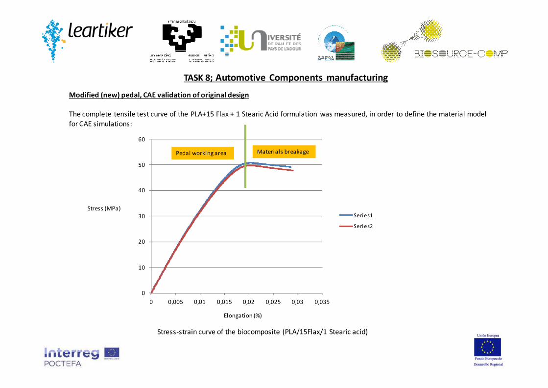
Modified (new) pedal, CAE validation of original design
The complete tensile test curve of the PLA+15 Flax + 1 Stearic Acid formulation was measured, in order to define the material model
for CAE simulations:
0
10
20
30
40
50
60
0 0,005 0,01 0,015 0,02 0,025 0,03 0,035
Series1
Series2
Elongation (%)
Stress (MPa)
Pedal working area Materials breakage
Stress-strain curve of the biocomposite (PLA/15Flax/1 Stearic acid)

TASK 8; Automotive Components manufacturing
Modified (new) pedal, CAE validation of original design
Simulations on the original design, with biocomposite material lead to:
Lateral load test is not a problem, but on the frontal load test, the maximum allowable stress is achieved, so the pedal could
get into plasticity area, breaking or/and not recovering initial shape.
-Frontal load of 900 N can lead to a
maximum deformation of 25 mm.
-Side load of 200 N can lead to a
maximum deformation of 30 mm.

Modified (new) pedal, design development + Structural CAE validation
Evolution of the design (July-August 2014).
TASK 8; Automotive Components manufacturing
Initial design Design V3; thicker ribs Design V4; Frontal increase Design V5; Lateral increase 1 Design V4; Back increase
Design V10; Lateral increase 2
Design V12; Lateral increase 3
Frontal load gives a maximum stress of 36
MPa, and max strain of 0,008 %, so below
material limit of the biocomposite
Design need to be optimized to be injectable!!!

TASK 8; Automotive Components manufacturing
Modified (new) pedal, design development + Structural CAE validation
September-October 2014; Simulations with the optimized (processable) pedal design were done. Pedal design was modified
in different versions, to fulfil the requirement of no material breakage.
CAD; Design V12 + Process validated; Validation date: 8th Oct 2014)
Bending on (frontal
loading): < 17 mm
Maximum stress level on
the part (frontal loading):
46 MPa
Video
Video
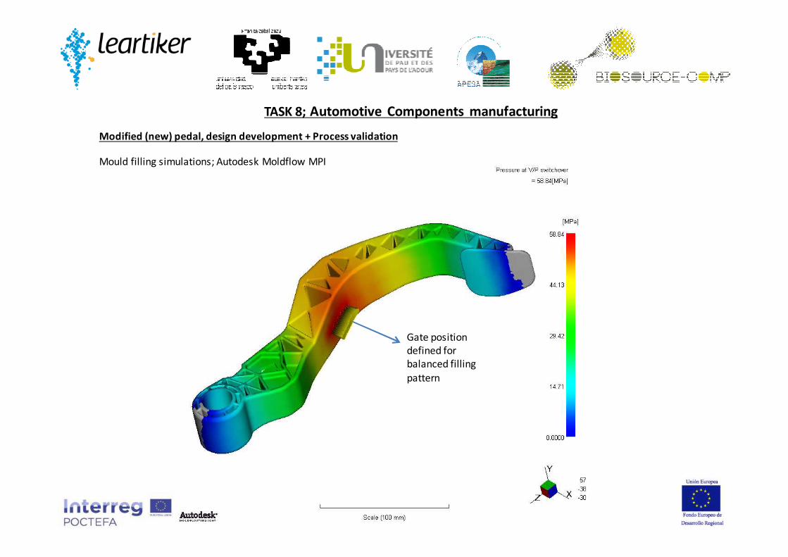
Gate position
defined for
balanced filling
pattern
TASK 8; Automotive Components manufacturing
Modified (new) pedal, design development + Process validation
Mould filling simulations; Autodesk Moldflow MPI
TASK 8; Automotive Components manufacturing
Modified (new) pedal
New pedal design was delivered to mould maker.
Estimate date for new mould reception in Leartiker is set to the 2nd week of January 2015
Then, injection trials will be done with the same biocomposite tested on before trials.
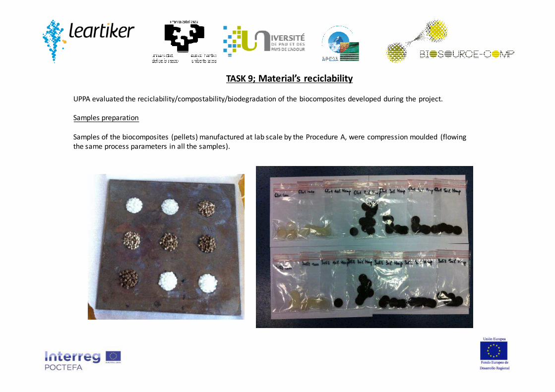
UPPA evaluated the reciclability/compostability/biodegradation of the biocomposites developed during the project.
Samples preparation
Samples of the biocomposites (pellets) manufactured at lab scale by the Procedure A, were compression moulded (flowing
the same process parameters in all the samples).
TASK 9; Material’s reciclability

Test procedure
Samples preparation (12% H.R Stabilisation)
Drying (103°C, 72h) and Conditioning(sterilization UV : 1h, 20°C for each side)
Confrontation with fungi (25°C, 70% H.R, during 16 weeks)
Weighting (M2)
Coriolus versicolor
Coniophora Puteana
Standard 15534-1. « Testing method for wood polymer composites
caracterisation ».
Weighting (Mo)
Cleaning of the samples surface
Weighting (M1)
Drying (103°C, 72h)
Weight Loss(%) = 100x(M0-M2)/M0
2 control samples
TASK 9; Material’s reciclability

TASK 9; Material’s reciclability
0
1
2
3
4
5
6
7
8
9
10
Com Reex 10% 20% 30% 40% 50%
6201
3052% W
eig
ht -
los
s
Com Reex 10% 20% 30% 40% 50%
PLA 6201 0,25 0,29 1,13 2,26 3,43 5,70 6,58
PLA 3052 1,15 1,1800 1,66 2,57 2,89 4,22 7,59
PLA-Hemp Biocomposites (Procedure A); weight loss and humidity control, Comparison to control sample (wood)
0
5
10
15
20
25
30
35
1 2 3 4 5 6 7
ReexCom
10%20%
30%40%
50%
(%)
we
igh
t-lo
ss
Control

TASK 9; Material’s reciclability
PLA-Flax Biocomposites (Procedure A); weight loss and humidity control, Comparison to control sample (wood)
0
1
2
3
4
5
6
7
8
9
10% 20% 30% 40% 50%
% Fiber
% W
eig
ht lo
ss
6201
3052
10% 20% 30% 40% 50%
PLA 6201 1,592 3,747 3,225 4,428 *
PLA 3052 1,405 * 5,804 * 7,019
(%) weight-loss of the control = 52,646 %
(*) : not tested because there were no 2 mm thick samples
0,00
2,00
4,00
6,00
8,00
10,00
12,00
10% 20% 30% 40% 50%
% Fibe r
% H
umid
ity
6201
3052
% Humidity of the control = 61,27 %
(*) : not tested because there were no 2 mm thick samples

0
2
4
6
8
10
12
14
16
3052Nm 2 35% 3052Nm 2 17,5% 3052+10% PEG
% H
% weight-loss
3052Nm2 35% 3052Nm2 17,5% 3052+10% PEG
% Humidity 14,06 ± 0,62 7,12 ± 0,75 10,53 ± 0,18
% weight-loss 6,21 ± 0,11 2,59 ± 0,31 8,74 ± 0,89
TASK 9; Material’s reciclability
PLA –Flax Biocomposites (manufactured by Procedure B); weight loss and humidity control, Comparison to control sample (wood)
Similar results to procedure A
TASK 9; Material’s reciclability
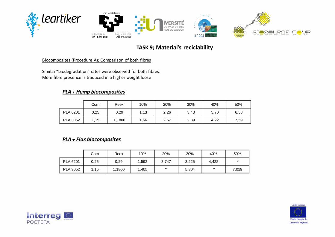
Com Reex 10% 20% 30% 40% 50%
PLA 6201 0,25 0,29 1,13 2,26 3,43 5,70 6,58
PLA 3052 1,15 1,1800 1,66 2,57 2,89 4,22 7,59
PLA + Hemp biocomposites
PLA + Flax biocomposites
Com Reex 10% 20% 30% 40% 50%
PLA 6201 0,25 0,29 1,592 3,747 3,225 4,428 *
PLA 3052 1,15 1,1800 1,405 * 5,804 * 7,019
Biocomposites (Procedure A); Comparison of both fibres
Similar “biodegradation” rates were observed for both fibres.
More fibre presence is traduced in a higher weight loose

TASK 10; Dissemination of results
Presence on the most important European trade fairs:
- Fakuma 2014, October 2014; Friedrichshafen, Germany
- FIP Solution 2014, June 2014; Lyon, France
- Equiplast 2014; October 2014; Barcelona, Spain
Preparation of technical/scientific papers
- Effect of the compounding process on the final properties of a PLA/flax composite for automotive industry. (In preparation)
Technical/scientific posters conferences:
-“Influence of the compounding procedure on the manufacturing of polylactic Acid (PLA) and natural fibre biocomposites. Evaluation
of biocomposite performance (BIOSOURCE-COMP project).” JEC Technical posters; ICS Innovative Composites Summit; JEC Asia
(Singapore 17-19 Nov 2014) and JEC America (Atlanta USA 13-15 May 2014 and Boston USA 28-29 Oct 2014)
- “Development of Natural fiber-Polylactic Acid biocomposites, for automotive clutch pedal”; Refused as JEC Plenary lecture on JEC
Europe 2014, and will try again on JEC Europe 2015
- “Development of Natural fiber-Polylactic Acid biocomposites, for automotive clutch pedal”; Marrakech ICFPAM ; 30 March - 02 April
2015 (http://www.icfpam2015.com/)
- “Effets de la méthode d’introduction de la fibre de lin dans le procédé d’extrusion-injection de composites PLA/lin sur les propriétés
physiques d’une pédale d’embrayage d’automobile” 19èmes Journées Nationales sur les Composites; 29 juin-1 juil. 2015 ;
Villeurbanne (France) http://jnc2015.sciencesconf.org/
Technical/scientific magazines
-Boletin Grupo Español de Reologia, nº 12, April –june 2014;
-IZARO news platform: http://www.izaro.com/contenidos/ver.php?id=es&se=2&su=21&co=1392127151&utm_medium=ema
+ Today presentation!!!

Future contact:
LEARTIKER; Lea Artibai Ikastetxea S.Coop.
Dr. Alex Arrillaga; [email protected]; +(34) 94 616 9171
www.leartiker.com
Thank you!!!