Embed Size (px)
Citation preview
PASSPORT ACTIVITY WALL(current) 5-2015
Tools Required and Initial Notes
Tools Required For Assembly
• 2 -3 People
• Phillips Head Screwdriver
• Drill with #2 Phillips bit
• Allen wrench set
• 5/32” Allen bit for a drill
• ¼” Allen bit for drill or screw driver
• Level
• Rubber Mallet
• Hardware Included
• Connector Bolts
• MDP track (If MDP unit included)
• Wire manager
Initial Notes
• Pictures in instructions may not represent the exact table being installed.
• Read all instructions thoroughly prior to beginning the installation.
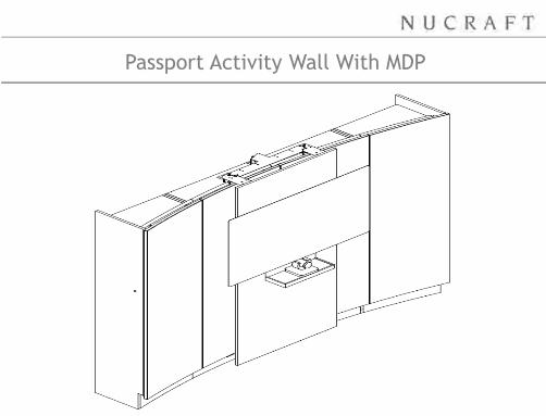
Passport Activity Wall With MDP
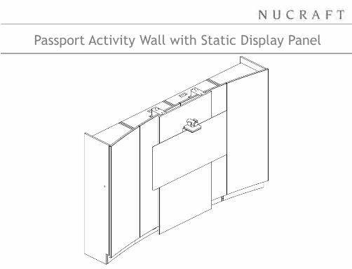
Passport Activity Wall with Static Display Panel
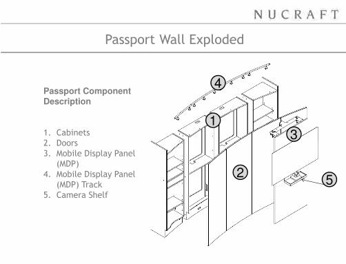
Passport Wall Exploded
Passport Component
Description
1. Cabinets
2. Doors
3. Mobile Display Panel
(MDP)
4. Mobile Display Panel
(MDP) Track
5. Camera Shelf
1
2
3
4
5
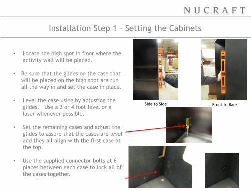
Installation Step 1 – Setting the Cabinets
• Locate the high spot in floor where the
activity wall will be placed.
• Be sure that the glides on the case that
will be placed on the high spot are run
all the way in and set the case in place.
• Level the case using by adjusting the
glides. Use a 2 or 4 foot level or a
laser whenever possible.
• Set the remaining cases and adjust the
glides to assure that the cases are level
and they all align with the first case at
the top.
• Use the supplied connector bolts at 6
places between each case to lock all of
the cases together.
Side to Side Front to Back
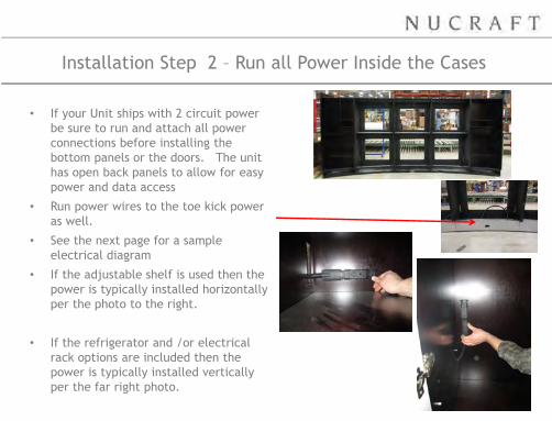
Installation Step 2 – Run all Power Inside the Cases
• If your Unit ships with 2 circuit power
be sure to run and attach all power
connections before installing the
bottom panels or the doors. The unit
has open back panels to allow for easy
power and data access
• Run power wires to the toe kick power
as well.
• See the next page for a sample
electrical diagram
• If the adjustable shelf is used then the
power is typically installed horizontally
per the photo to the right.
• If the refrigerator and /or electrical
rack options are included then the
power is typically installed vertically
per the far right photo.
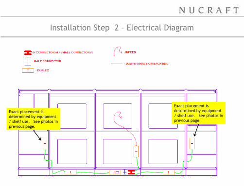
Installation Step 2 – Electrical Diagram
Exact placement is
determined by equipment
/ shelf use. See photos in
previous page.
Exact placement is
determined by equipment
/ shelf use. See photos in
previous page.
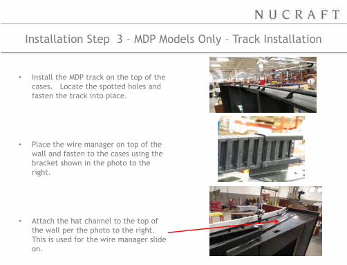
Installation Step 3 – MDP Models Only – Track Installation
• Install the MDP track on the top of the
cases. Locate the spotted holes and
fasten the track into place.
• Place the wire manager on top of the
wall and fasten to the cases using the
bracket shown in the photo to the
right.
• Attach the hat channel to the top of
the wall per the photo to the right.
This is used for the wire manager slide
on.
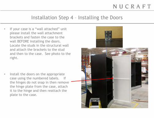
Installation Step 4 – Installing the Doors
• If your case is a “wall attached” unit
please install the wall attachment
brackets and fasten the case to the
wall BEFORE installing the doors.
Locate the studs in the structural wall
and attach the brackets to the stud
and then to the case. See photo to the
right.
• Install the doors on the appropriate
case using the numbered labels. If
the hinges do not snap in then remove
the hinge plate from the case, attach
it to the hinge and then reattach the
plate to the case.
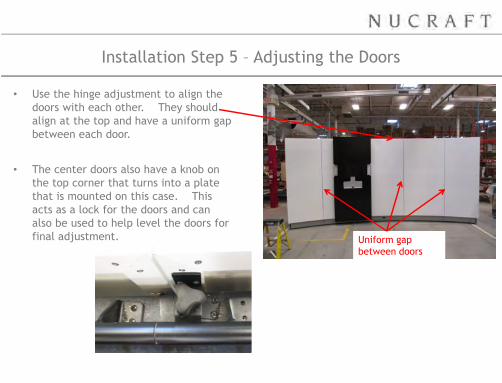
Installation Step 5 – Adjusting the Doors
• Use the hinge adjustment to align the
doors with each other. They should
align at the top and have a uniform gap
between each door.
• The center doors also have a knob on
the top corner that turns into a plate
that is mounted on this case. This
acts as a lock for the doors and can
also be used to help level the doors for
final adjustment. Uniform gap
between doors
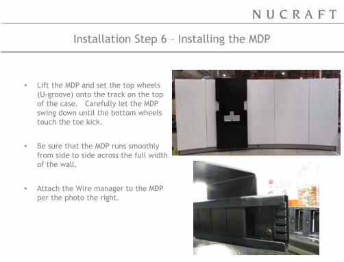
Installation Step 6 – Installing the MDP
• Lift the MDP and set the top wheels
(U-groove) onto the track on the top
of the case. Carefully let the MDP
swing down until the bottom wheels
touch the toe kick.
• Be sure that the MDP runs smoothly
from side to side across the full width
of the wall.
• Attach the Wire manager to the MDP
per the photo the right.
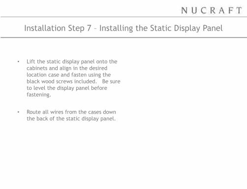
Installation Step 7 – Installing the Static Display Panel
• Lift the static display panel onto the
cabinets and align in the desired
location case and fasten using the
black wood screws included. Be sure
to level the display panel before
fastening.
• Route all wires from the cases down
the back of the static display panel.
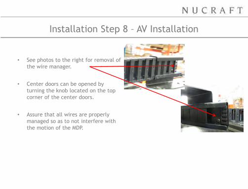
Installation Step 8 – AV Installation
• See photos to the right for removal of
the wire manager.
• Center doors can be opened by
turning the knob located on the top
corner of the center doors.
• Assure that all wires are properly
managed so as to not interfere with
the motion of the MDP.