Embed Size (px)
Citation preview
Consult | Components | Logistics | Support
Committed to excellence
Passive Components
Ceramic Capacitors
2
Overview Ceramic Capacitors
Overview MLCC
High Cap MLCC
Stacked MLCC
Tantalum Replacement
MLCC Crack &
Short Circuit Protection
High Temperature
Save Space
High Voltage MLCC
Safety & Suppression Capacitors
High Frequency &
RF Microwave Chips
Low Inductance
Feedthru & X2Y
Capacitor Technology
Comparison & Main Functions
04/05
06/07
08
09
10/11
12-14
15
16/17
18
19
20
21
22
23
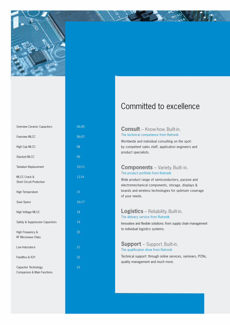
Committed to excellence
Consult – Know-how. Built-in. The technical competence from Rutronik
Worldwide and individual consulting on the spot:
by competent sales staff, application engineers and
product specialists.
Components – Variety. Built- in. The product portfolio from Rutronik
Wide product range of semiconductors, passive and
electromechanical components, storage, displays &
boards and wireless technologies for optimum coverage
of your needs.
Logistics – Reliability. Built-in. The delivery service from Rutronik
Innovative and flexible solutions: from supply chain management
to individual logistics systems.
Support – Support. Built-in.The qualification drive from Rutronik
Technical support: through online services, seminars, PCNs,
quality management and much more.
3
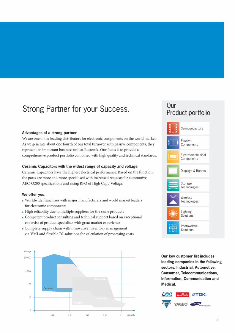
Advantages of a strong partner We are one of the leading distributors for electronic components on the world market. As we generate about one fourth of our total turnover with passive com ponents, they represent an important business unit at Rutronik. Our focus is to provide a comprehensive product portfolio combined with high quality and technical standards. Ceramic Capacitors with the widest range of capacity and voltageCeramic Capacitors have the highest electrical performance. Based on the function, the parts are more and more specialised with increased requests for automotive AEC-Q200 specifications and rising RFQ of High Cap / Voltage.
We offer you: Worldwide franchises with major manufacturers and world market leaders
for electronic components High reliability due to multiple suppliers for the same products Competent product consulting and technical support based on exceptional expertise of product specialists with great market experience
Complete supply chain with innovative inventory management via VMI and flexible DI solutions for calculation of processing costs
Our key customer list includes leading companies in the following sectors: Industrial, Automotive, Consumer, Telecommunications, Information, Communication and Medical.
Strong Partner for your Success.
Voltage
10,000
1,000
100
10
Capacity
1
1 pF 1 nF 1 µF 1 mF 1 F
Film
Tantalum
Electrolytic
Supercap
Ceramic
®
Semiconductors
PassiveComponents
ElectromechanicalComponents
Storage Technologies
Displays & Boards
WirelessTechnologies
PhotovoltaicSolutions
LightingSolutions
OurProduct portfolio
4
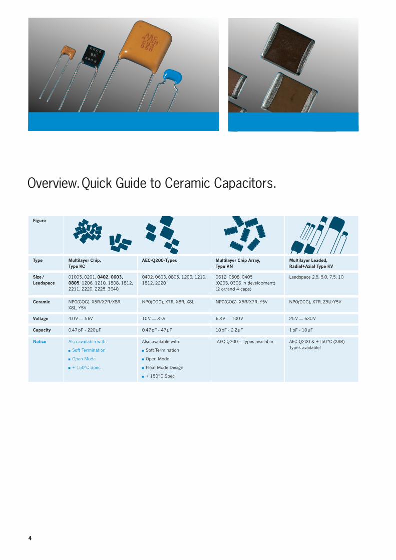
Figure
Type Multilayer Chip, Type KC
AEC-Q200-Types Multilayer Chip Array, Type KN
Multilayer Leaded, Radial+Axial Type KV
Size /Leadspace
01005, 0201, 0402, 0603, 0805, 1206, 1210, 1808, 1812, 2211, 2220, 2225, 3640
0402, 0603, 0805, 1206, 1210, 1812, 2220
0612, 0508, 0405 (0203, 0306 in development)(2 or/and 4 caps)
Leadspace 2.5, 5.0, 7.5, 10
Ceramic NP0(COG), X5R/X7R/X8R, X8L, Y5V
NP0(COG), X7R, X8R, X8L NP0(COG), X5R/X7R, Y5V NP0(COG), X7R, Z5U/Y5V
Voltage 4.0 V .... 5 kV 10 V .... 3 kV 6.3 V .... 100 V 25 V .... 630 V
Capacity 0.47 pF - 220 μF 0.47 pF - 47 μF 10 pF - 2.2 μF 1 pF - 10 μF
Notice Also available with:
Soft Termination
Open Mode
+ 150°C Spec.
Also available with:
Soft Termination
Open Mode
Float Mode Design
+ 150° C Spec.
AEC-Q200 – Types available AEC-Q200 & +150 °C (X8R) Types available!
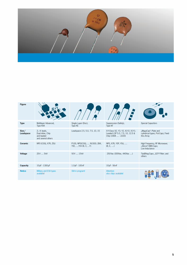
Overview. Quick Guide to Ceramic Capacitors.
5
Figure
Type Multilayer Advanced, Type KVA
Single Layer (Disc), Type KE
Suppression (Safety), Type KF
Special Capacitors
Size /Leadspace
2-, 4- leads,Dual inline, Chipand leadedand several others
Leadspace 2.5, 5.0, 7.5, 10, 15 X-Y-Class X2, Y3, Y2, X1Y2, X1Y1;Leaded LSP 5.0, 7.5, 10, 12.5 & Chip (1808 .... - 2220)
„MegaCap“; Plate and cylindrical types; Pot-Caps; Feed-thru Array
Ceramic NP0 (COG), X7R, Z5U P100, NP0(COG), .... N1500; 2B4, Y5E, ....Y5V (B, C, .. F)
NP0, X7R, Y5P, Y5U, .... (B, E, ....)
High Frequency, RF Microwave;„Silicon“-SMD-Caps; Low Inductance
Voltage 25 V .... 5 kV 50 V .... 15 kV 250 Vac (300Vac, 440Vac ....) Tip&Ring-Caps; „X2Y“-Filter; and others
Capacity 10 pF - 1300 μF 1.0 pF - 100 nF 10 pF - 56 nF
Notice Military and ESA types available!
Still in program! Attention: also chips available!
6
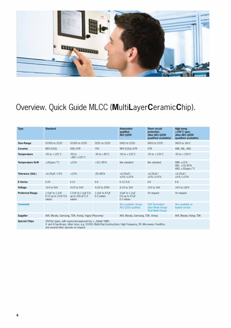
Overview. Quick Guide MLCC (MultiLayerCeramicChip).
Type Standard Automotive qualified AEC-Q200
Short circuit protection (Also AEC-Q200 qualified available)
High temp. +150˚C spec. (Also AEC-Q200 qualified available)
Size-Range 01005 to 2220 01005 to 2220 0201 to 2220 0402 to 2220 0603 to 2220 0603 to 1812
Ceramic NP0 (COG) X5R / X7R Y5V NP0 (COG) / X7R X7R X8R, X8L, X8G
Temperature -55 to + 125 ̊ C -55 to + 85 / +125 ̊ C
-30 to + 85˚C -55 to + 125˚C -55 to + 125˚C -55 to + 150˚C
Temperature Drift ±30 ppm / °C ±15 % +22 / -85 % like standard like standard X8R: ±15 % X8L: +15/-40 %X8G: ±30 ppm / °C
Tolerance (Std.) ±0.25 pF / ±5 % ±10 % -20+80 % ±0.25 pF /±5 % / ±10 %
±0.25 pF /±5 % / ±10 %
±0.25 pF / ±5 % / ±10 %
E-Series E-24 E-12 E-6 E-12 / E-6 E-6 E-6
Voltage 10 V to 5 kV 4.0 V to 5 kV 4.0 V to 250V 6.3 V to 3 kV 10 V to 3 kV 16 V to 100 V
Preferred Range 1.0 pF to 1.0 nF E-12 up to 10 nF E-6 values
1.0 nF to 1.0 µF E-6 up to 220 µF E-3 values
1.0 µF to 47 µF E-3 values
10 pF to 1.0 µF E-6 up to 47 µF E-3 values
On request On request
Comment Also available: Arrays AEC-Q200 qualified
Soft TerminationOpen Mode DesignFloat Mode Design
Also available as leaded version
Supplier AVX, Murata, Samsung, TDK, Vishay, Yageo (Phycomp) AVX, Murata, Samsung, TDK, Vishay AVX, Murata, Vishay, TDK
Special Chips 250 Vac types, with supression-approval too = „Safety“-SMD; 2- and 4-Cap-Arrays; other sizes, e.g. 01005; Multi-Chip-Constructions; High Frequency, FR, Microwave; Feedthru; and several other specials on request
7
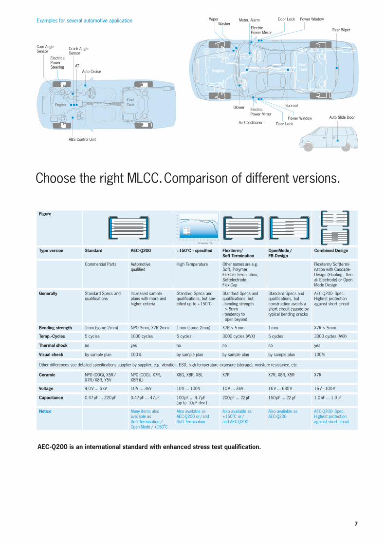
Choose the right MLCC. Comparison of different versions.
Examples for several automotive application
Cam Angle Sensor
Crank Angle Sensor
AT
EngineFuelTank
FuelTankEngine
ElectricalPower Steering
ABS Control Unit
Auto Cruise
WiperWasher
Meter, Alarm
Electric Power Mirror
Door Lock Power Window
Rear Wiper
SunroofBlower
Air Conditioner
Electric Power Mirror
Door LockPower Window Auto Slide Door
AEC-Q200 is an international standard with enhanced stress test qualification.
Figure
Type version Standard AEC-Q200 +150ºC - specified Flexiterm/Soft Termination
OpenMode / FR-Design
Combined Design
Commercial Parts Automotive qualified
High Temperature Other names are e.g. Soft, Polymer, Flexible Termination, Softelectrode, FlexiCap
Flexiterm/ Softtermi-nation with Cascade-Design (Floating-, Seri-al- Electrode) or Open Mode Design
Generally Standard Specs and qualifications
Increased sample plans with more and higher criteria
Standard Specs and qualifications, but spe-cified up to +150˚C
Standard Specs and qualifications, but:- bending strength > 5mm- tendency to open beyond
Standard Specs and qualifications, but construction avoids a short circuit caused by typical bending cracks
AEC-Q200- Spec.Highest protection against short circuit
Bending strength 1mm (some 2 mm) NPO 3mm, X7R 2mm 1 mm (some 2 mm) X7R > 5 mm 1 mm X7R > 5 mm
Temp.-Cycles 5 cycles 1000 cycles 5 cycles 3000 cycles (AVX) 5 cycles 3000 cycles (AVX)
Thermal shock no yes no no no yes
Visual check by sample plan 100 % by sample plan by sample plan by sample plan 100 %
Other differences see detailed specifications supplier by supplier, e.g. vibration, ESD, high temperature exposure (storage), moisture resistance, etc.
Ceramic NP0 (COG), X5R / X7R / X8R, Y5V
NP0 (COG), X7R, X8R (L)
X8G, X8R, X8L X7R X7R, X8R, X5R X7R
Voltage 4.0 V ... 5 kV 10 V ... 3 kV 10 V ... 100 V 10 V ... 3 kV 16 V ... 630 V 16 V - 100 V
Capacitance 0.47 pF ... 220 µF 0.47 pF ... 47 µF 100 pF ... 4.7 µF (up to 10 µF dev.)
200 pF ... 22 µF 150 pF ... 22 µF 1.0 nF ... 1.0 µF
Notice Many items also available as Soft Termination /Open Mode / +150ºC
Also available as AEC-Q200 or / andSoft Termination
Also available as +150ºC or / and AEC-Q200
Also available as AEC-Q200
AEC-Q200- Spec.Highest protection against short circuit
20
100
–10
–20
–30
–40
–50
–60 –40 –20 0 20 40 60 80 100 120 140 160
Temperature [°C]
X8L
X8R
X8G
8
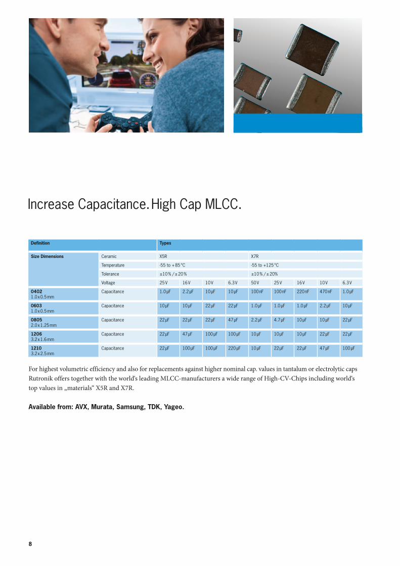
Increase Capacitance. High Cap MLCC.
For highest volumetric efficiency and also for replacements against higher nominal cap. values in tantalum or electrolytic caps Rutronik offers together with the world‘s leading MLCC-manufacturers a wide range of High-CV-Chips including world‘s top values in „materials“ X5R and X7R.
Available from: AVX, Murata, Samsung, TDK, Yageo.
Definition Types
Size Dimensions Ceramic X5R X7R
Temperature -55 to + 85 °C -55 to +125 °C
Tolerance ±10 % / ± 20 % ±10 % / ± 20%
Voltage 25 V 16 V 10 V 6.3 V 50 V 25 V 16 V 10 V 6.3 V
04021.0 x 0.5 mm
Capacitance 1.0 µF 2.2 µF 10 µF 10 µF 100 nF 100 nF 220 nF 470 nF 1.0 µF
06031.0 x 0.5 mm
Capacitance 10 µF 10 µF 22 µF 22 µF 1.0 µF 1.0 µF 1.0 µF 2.2 µF 10 µF
08052.0 x 1.25 mm
Capacitance 22 µF 22 µF 22 µF 47 µF 2.2 µF 4.7 µF 10 µF 10 µF 22 µF
12063.2 x 1.6 mm
Capacitance 22 µF 47 µF 100 µF 100 µF 10 µF 10 µF 10 µF 22 µF 22 µF
12103.2 x 2.5 mm
Capacitance 22 µF 100 µF 100 µF 220 µF 10 µF 22 µF 22 µF 47 µF 100 µF
9
Series Structure Capaci-tance
Voltage Number of Stacked MLCC
MegaCap (TDK)
47 nF - 100 µF
16 V - 630 V 1 - 2
KRM + KCM 330 nF - 47µF
25 V - 630 V 1 - 2
RH (AVX)
47nF - 47µF 50V - 500 V 1 - 2
Stacked MLC SM + RM (AVX)
10nF - 1300 µF
50V - 500 V 1 - 5
TurboCap (AVX)
820nF - 220 µF
25V - 100 V (500 V in dev.)
3, 5, 10
MH (AVX)
1.0 µF - 22 µF
25 V - 100 V 1
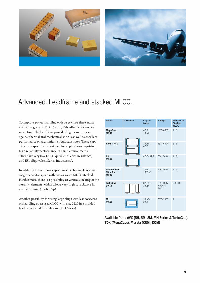
Advanced. Leadframe and stacked MLCC.
To improve power handling with large chips there exists a wide program of MLCC with „J“-leadframe for surfacemounting. The leadframe provides higher robustness against thermal and mechanical shocks as well as excellent performance on aluminium circuit substrates. These capa-citors are specifically designed for applications requiring high reliability performance in harsh environments. They have very low ESR (Equivalent Series Resistance) and ESL (Equivalent Series Inductance).
In addition to that more capacitance is obtainable on one single capacitor space with two or more MLCC stacked. Furthermore, there is a possibility of vertical stacking of the ceramic elements, which allows very high capacitance in a small volume (TurboCap).
Another possiblity for using large chips with less concerns on handling stress is a MLCC with size 2220 in a molded leadframe tantalum style case (MH Series).
Available from: AVX (RH, RM, SM, MH Series & TurboCap), TDK (MegaCaps), Murata (KRM + KCM)
10
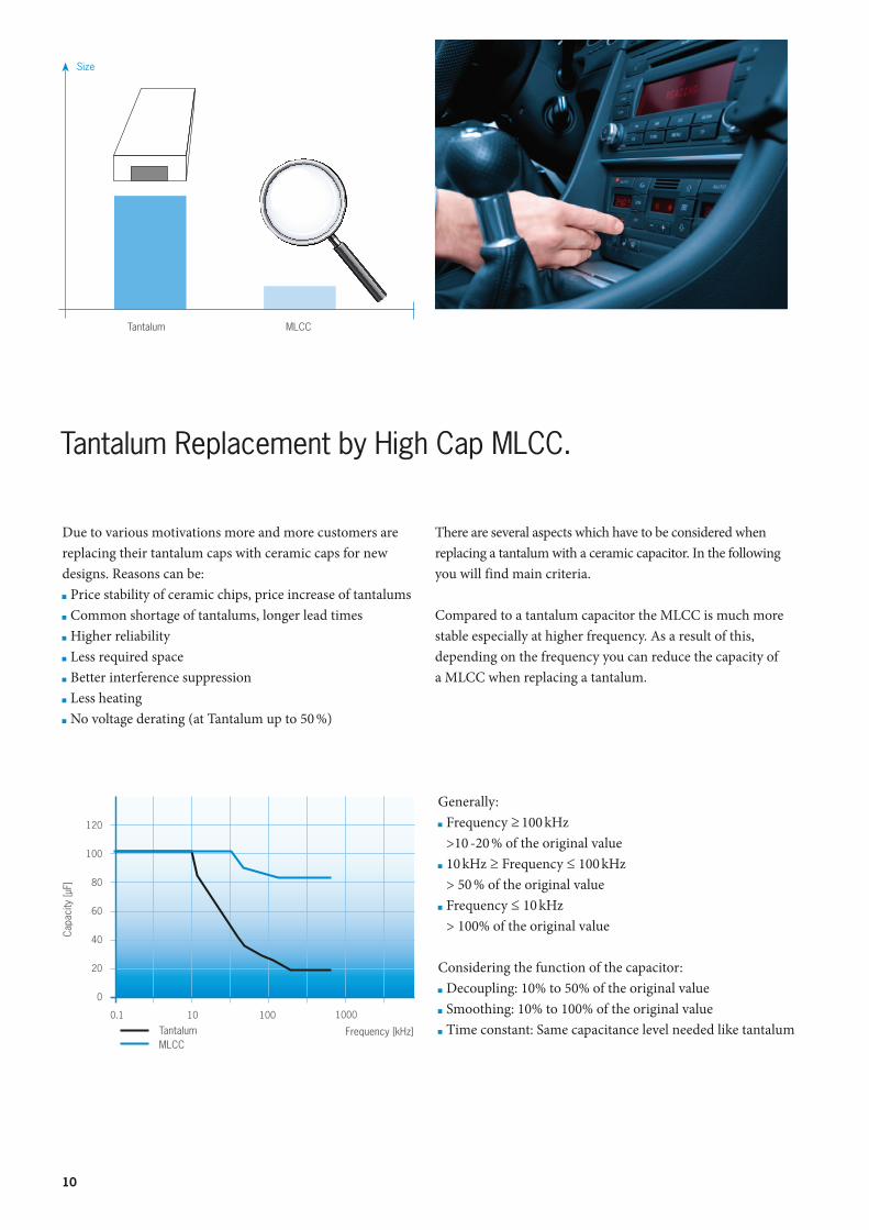
Due to various motivations more and more customers are replacing their tantalum caps with ceramic caps for new designs. Reasons can be: Price stability of ceramic chips, price increase of tantalums Common shortage of tantalums, longer lead times Higher reliability Less required space Better interference suppression Less heating No voltage derating (at Tantalum up to 50 %)
Tantalum Replacement by High Cap MLCC.
There are several aspects which have to be considered when replacing a tantalum with a ceramic capacitor. In the following you will find main criteria.
Compared to a tantalum capacitor the MLCC is much more stable especially at higher frequency. As a result of this, depending on the frequency you can reduce the capacity of a MLCC when replacing a tantalum.
Generally: Frequency ≥ 100 kHz
>10 -20 % of the original value 10 kHz ≥ Frequency ≤ 100 kHz
> 50 % of the original value Frequency ≤ 10 kHz
> 100% of the original value
Considering the function of the capacitor: Decoupling: 10% to 50% of the original value Smoothing: 10% to 100% of the original value Time constant: Same capacitance level needed like tantalum
120
100
80
60
40
20
0
0.1 10 100 1000
Frequency [kHz]
Capa
city
[µF]
TantalumMLCC
Size
Tantalum MLCC
11
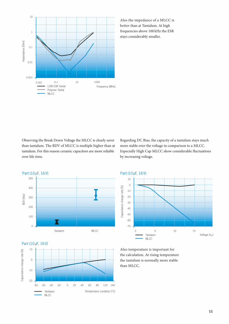
Observing the Break Down Voltage the MLCC is clearly saver than tantalum. The BDV of MLCC is multiple higher than at tantalum. For this reason ceramic capacitors are more reliable over life time.
1
0.1
0.01
0.001
0.001 0.1 10 1000
Frequency [MHz]
Impe
ndan
ce [O
hm]
LOW ESR TantalPolymer TantalMLCC
Regarding DC Bias, the capacity of a tantalum stays much more stable over the voltage in comparison to a MLCC. Especially High Cap MLCC show considerable fluctuations by increasing voltage.
Also the impedance of a MLCC is better than at Tantalum. At high frequencies above 100 kHz the ESR stays considerably smaller.
Also temperature is important for the calculation. At rising temperature the tantalum is normally more stable than MLCC.
10
500
400
300
200
100
0
MLCC
BDV
[Vdc
]
Tantalum
Part (10 µF, 16 V)
0
-20
-30
-40
-50
-60
-70
0 5 10 15
Voltage [Vdc ]
Capa
cita
nce
chan
ge r
ate
[%]
TantalumMLCC
-10
10
Part (10 µF, 16 V) 10
0
-10
-20Capa
cita
nce
chan
ge r
ate
[%]
-80 -60 -40 -20 0 20 40 60 80 120 140
TantalumMLCC
Temperature condition [°C]
Part (10 µF, 16 V)
12
board
ceramic-terminal joing point
solder
terminal electrode
A
B
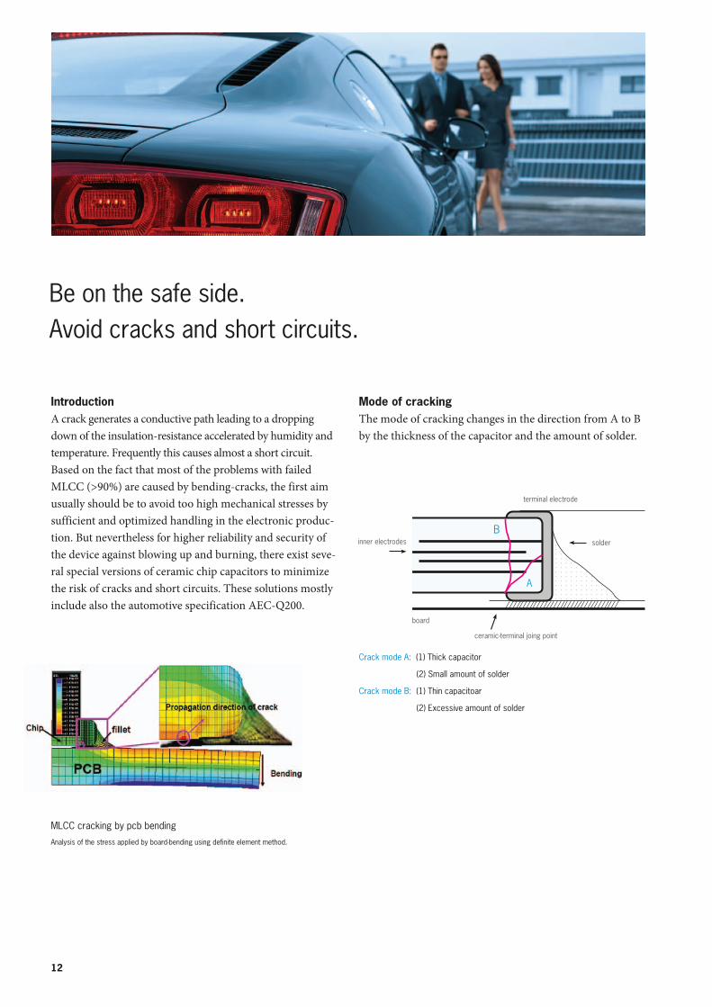
IntroductionA crack generates a conductive path leading to a dropping down of the insulation-resistance accelerated by humidity and temperature. Frequently this causes almost a short circuit.Based on the fact that most of the problems with failed MLCC (>90%) are caused by bending-cracks, the first aim usually should be to avoid too high mechanical stresses by sufficient and optimized handling in the electronic produc-tion. But nevertheless for higher reliability and security of the device against blowing up and burning, there exist seve-ral special versions of ceramic chip capacitors to minimize the risk of cracks and short circuits. These solutions mostly include also the automotive specification AEC-Q200.
Mode of crackingThe mode of cracking changes in the direction from A to B by the thickness of the capacitor and the amount of solder.
Crack mode A: (1) Thick capacitor
(2) Small amount of solder
Crack mode B: (1) Thin capacitoar
(2) Excessive amount of solder
MLCC cracking by pcb bending
Analysis of the stress applied by board-bending using definite element method.
Be on the safe side.Avoid cracks and short circuits.
inner electrodes
13
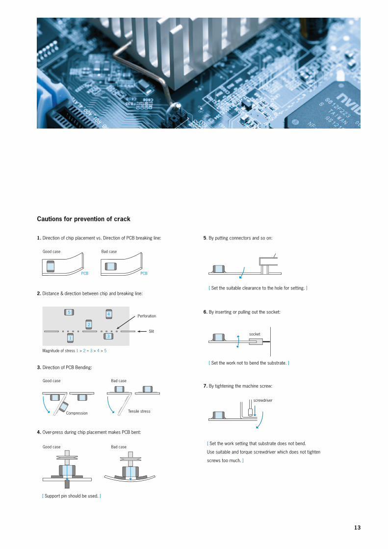
Cautions for prevention of crack
1. Direction of chip placement vs. Direction of PCB breaking line:
2. Distance & direction between chip and breaking line:
3. Direction of PCB Bending:
4. Over-press during chip placement makes PCB bent:
5. By putting connectors and so on:
6. By inserting or pulling out the socket:
7. By tightening the machine screw:
[ Support pin should be used. ]
[ Set the work setting that substrate does not bend.
Use suitable and torque screwdriver which does not tighten
screws too much. ]
Good case Bad case
Compression Tensile stress
Good case Bad case
Bad case
Perforation
Magnitude of stress 1 > 2 ≈ 3 > 4 > 5
Slit
Good case
PCB PCB
[ Set the work not to bend the substrate. ]
[ Set the suitable clearance to the hole for setting. ]
socket
screwdriver
11
2
5 4
311
2
5 4
311
2
5 4
311
2
5 4
311
2
5 4
311
2
5 4
311
2
5 4
3
14
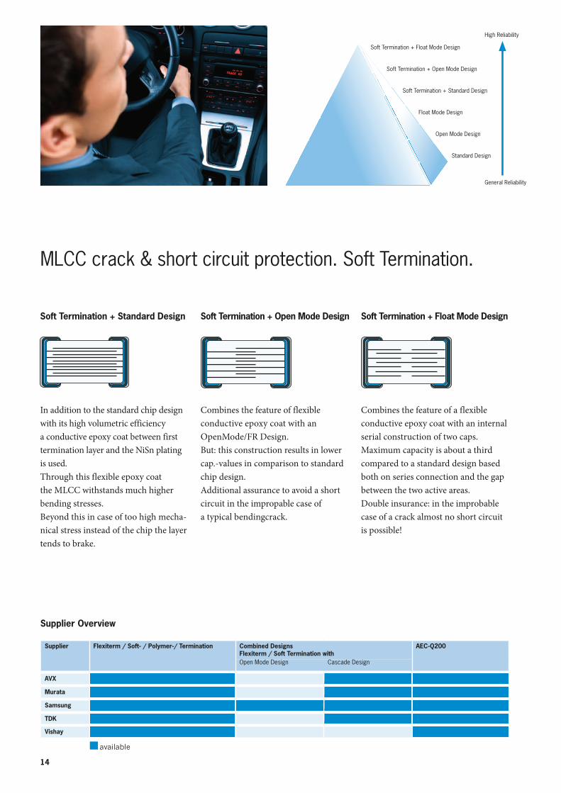
Soft Termination + Standard Design
In addition to the standard chip design with its high volumetric efficiency a conductive epoxy coat between first termination layer and the NiSn plating is used.Through this flexible epoxy coat the MLCC withstands much higher bending stresses.Beyond this in case of too high mecha-nical stress instead of the chip the layer tends to brake.
Soft Termination + Open Mode Design
Combines the feature of flexible conductive epoxy coat with an OpenMode/FR Design.But: this construction results in lower cap.-values in comparison to standard chip design.Additional assurance to avoid a short circuit in the impropable case of a typical bendingcrack.
Soft Termination + Float Mode Design
Combines the feature of a flexibleconductive epoxy coat with an internal serial construction of two caps.Maximum capacity is about a third compared to a standard design based both on series connection and the gap between the two active areas.Double insurance: in the improbable case of a crack almost no short circuit is possible!
MLCC crack & short circuit protection. Soft Termination.
Supplier Overview
Soft Termination + Float Mode Design
Soft Termination + Open Mode Design
Soft Termination + Standard Design
Float Mode Design
Open Mode Design
Standard Design
General Reliability
High Reliability
Supplier Flexiterm / Soft- / Polymer-/ Termination Combined Designs Flexiterm / Soft Termination with
AEC-Q200
Open Mode Design Cascade Design
AVX
Murata
Samsung
TDK
Vishay
available
15
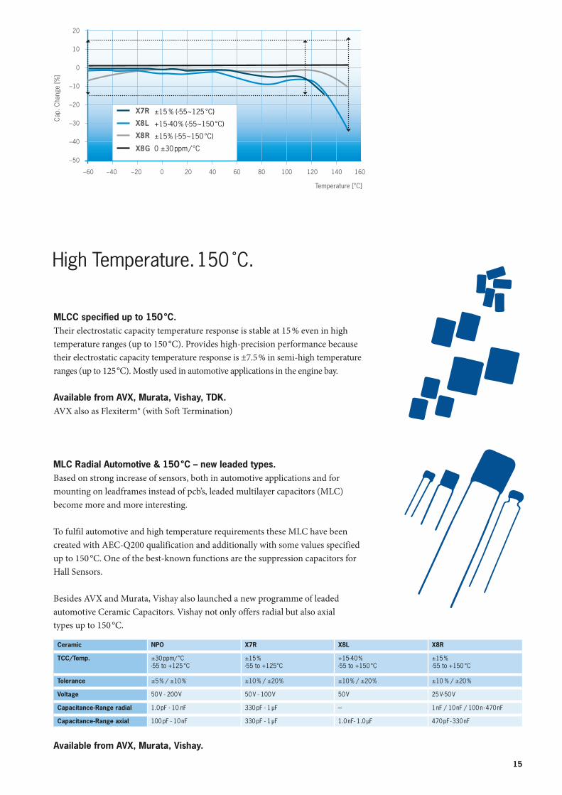
Ceramic NPO X7R X8L X8R
TCC/Temp. ±30 ppm/ °C-55 to +125 °C
±15 %-55 to +125°C
+15-40 %-55 to +150 °C
±15 %-55 to +150 °C
Tolerance ±5 % / ±10 % ±10 % / ±20 % ±10 % / ±20 % ±10 % / ±20 %
Voltage 50 V - 200 V 50 V - 100 V 50 V 25 V-50 V
Capacitance-Range radial 1.0 pF - 10 nF 330 pF - 1 µF --- 1 nF / 10 nF / 100 n - 470 nF
Capacitance-Range axial 100 pF - 10 nF 330 pF - 1 µF 1.0 nF- 1.0 µF 470 pF - 330 nF
MLCC specified up to 150 °C.Their electrostatic capacity temperature response is stable at 15 % even in high temperature ranges (up to 150 °C). Provides high-precision performance because their electrostatic capacity temperature response is ±7.5 % in semi-high temperature ranges (up to 125 °C). Mostly used in automotive applications in the engine bay.
Available from AVX, Murata, Vishay, TDK.AVX also as Flexiterm® (with Soft Termination)
MLC Radial Automotive & 150 °C – new leaded types.Based on strong increase of sensors, both in automotive applications and for mounting on leadframes instead of pcb’s, leaded multilayer capacitors (MLC) become more and more interesting.
To fulfil automotive and high temperature requirements these MLC have been created with AEC-Q200 qualification and additionally with some values specified up to 150 °C. One of the best-known functions are the suppression capacitors for Hall Sensors.
Besides AVX and Murata, Vishay also launched a new programme of leaded automotive Ceramic Capacitors. Vishay not only offers radial but also axial types up to 150 °C.
High Temperature. 150 ̊C.
Available from AVX, Murata, Vishay.
20
10
0
–10
–20
–30
–40
–50
–60 –40 –20 0 20 40 60 80 100 120 140 160
Temperature [°C]
X7R
X8L
X8R
X8G
±15 % (-55~125 °C)
+15-40 % (-55~150 °C)
±15% (-55~150 °C)
0 ±30 ppm / °C
Cap.
Cha
nge
[%]
16
0
10
20
30
40
50
60
70
80
90
100
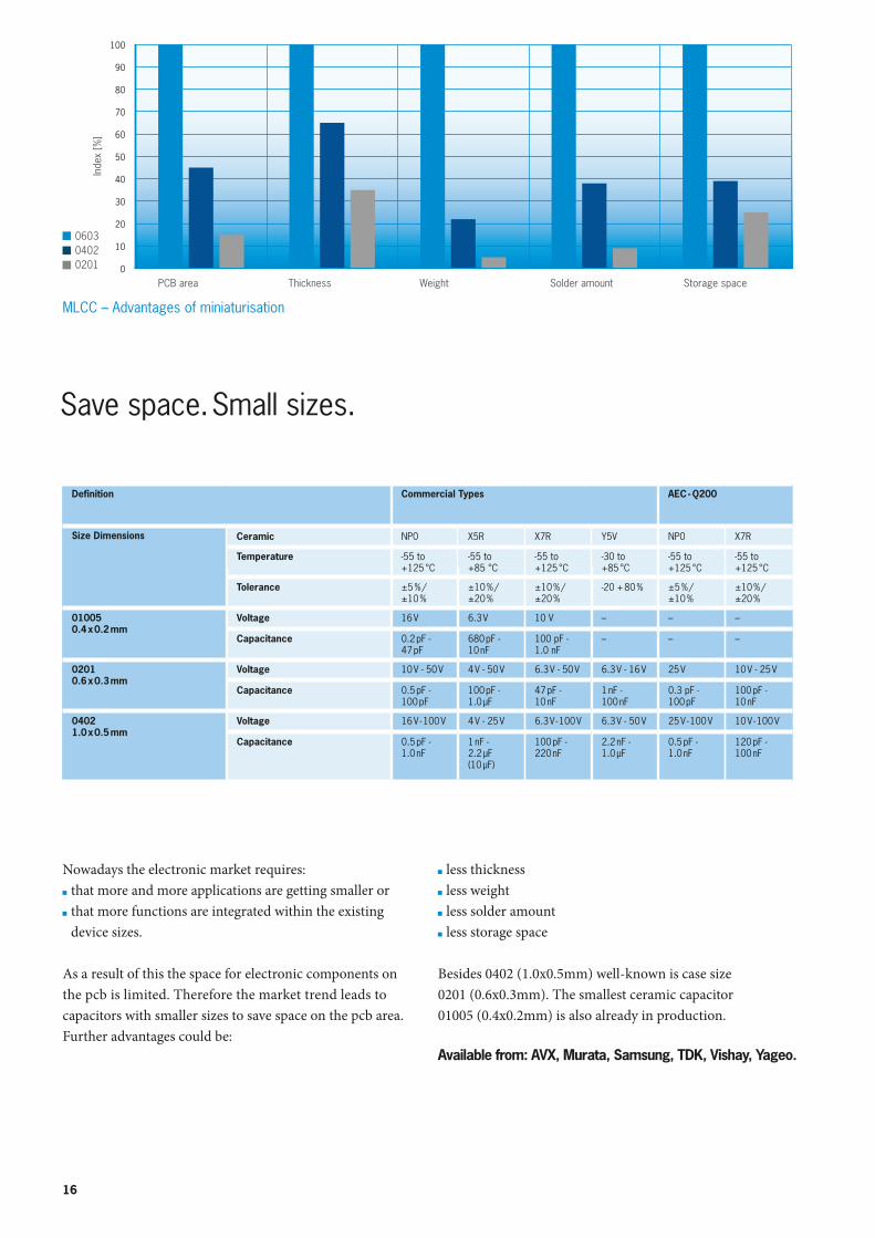
Save space. Small sizes.
Definition Commercial Types AEC - Q200
Size Dimensions Ceramic NP0 X5R X7R Y5V NP0 X7R
Temperature -55 to +125 °C
-55 to +85 °C
-55 to +125 °C
-30 to +85 °C
-55 to +125 °C
-55 to +125 °C
Tolerance ±5 % / ±10 %
±10 % / ±20 %
±10 % / ±20 %
-20 + 80 % ±5 % / ±10 %
±10 % / ±20 %
010050.4 x 0.2 mm
Voltage 16 V 6.3 V 10 V – – –
Capacitance 0.2 pF - 47 pF
680 pF - 10 nF
100 pF -1.0 nF
– – –
02010.6 x 0.3 mm
Voltage 10 V - 50 V 4 V - 50 V 6.3 V - 50 V 6.3 V - 16 V 25 V 10 V - 25 V
Capacitance 0.5 pF - 100 pF
100 pF - 1.0 µF
47 pF - 10 nF
1 nF - 100 nF
0.3 pF - 100 pF
100 pF - 10 nF
04021.0 x 0.5 mm
Voltage 16 V - 100 V 4 V - 25 V 6.3 V - 100 V 6.3 V - 50 V 25 V - 100 V 10 V - 100 V
Capacitance 0.5 pF - 1.0 nF
1 nF - 2.2 µF (10 µF)
100 pF - 220 nF
2.2 nF - 1.0 µF
0.5 pF - 1.0 nF
120 pF - 100 nF
Nowadays the electronic market requires: that more and more applications are getting smaller or that more functions are integrated within the existing device sizes.
As a result of this the space for electronic components on the pcb is limited. Therefore the market trend leads to capacitors with smaller sizes to save space on the pcb area. Further advantages could be:
less thickness less weight less solder amount less storage space
Besides 0402 (1.0x0.5mm) well-known is case size 0201 (0.6x0.3mm). The smallest ceramic capacitor 01005 (0.4x0.2mm) is also already in production.
Available from: AVX, Murata, Samsung, TDK, Vishay, Yageo.
Inde
x [%
]
PCB area Thickness Weight Solder amount Storage space
060304020201
MLCC – Advantages of miniaturisation
17
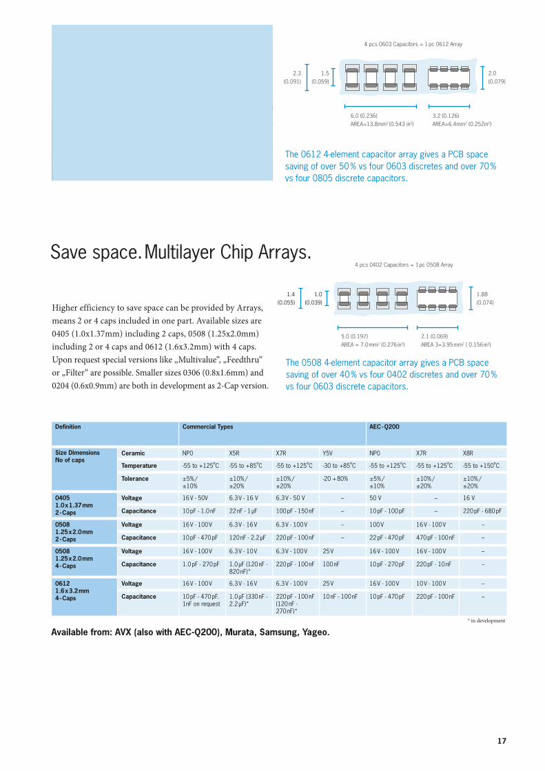
Higher efficiency to save space can be provided by Arrays, means 2 or 4 caps included in one part. Available sizes are 0405 (1.0x1.37mm) including 2 caps, 0508 (1.25x2.0mm) including 2 or 4 caps and 0612 (1.6x3.2mm) with 4 caps.Upon request special versions like „Multivalue“, „Feedthru“ or „Filter“ are possible. Smaller sizes 0306 (0.8x1.6mm) and 0204 (0.6x0.9mm) are both in development as 2-Cap version.
Save space. Multilayer Chip Arrays.
Definition Commercial Types AEC - Q200
Size DimensionsNo of caps
Ceramic NP0 X5R X7R Y5V NP0 X7R X8R
Temperature -55 to +125ºC -55 to +85ºC -55 to +125ºC -30 to +85ºC -55 to +125ºC -55 to +125ºC -55 to +150ºC
Tolerance ±5% / ±10%
±10% / ±20%
±10% / ±20%
-20 + 80% ±5% / ±10%
±10% / ±20%
±10% / ±20%
04051.0 x 1.37 mm2 - Caps
Voltage 16 V - 50V 6.3 V - 16 V 6.3 V - 50 V – 50 V – 16 V
Capacitance 10 pF - 1.0 nF 22 nF - 1 µF 100 pF - 150 nF – 10 pF - 100 pF – 220 pF - 680 pF
05081.25 x 2.0 mm2 - Caps
Voltage 16 V - 100 V 6.3 V - 16 V 6.3 V - 100 V – 100 V 16 V - 100 V –
Capacitance 10 pF - 470 pF 120 nF - 2.2 µF 220 pF - 100 nF – 22 pF - 470 pF 470 pF - 100 nF –
05081.25 x 2.0 mm4 - Caps
Voltage 16 V - 100 V 6.3 V - 10 V 6.3 V - 100 V 25 V 16 V - 100 V 16 V - 100 V –
Capacitance 1.0 pF - 270 pF 1.0 µF (120 nF - 820 nF)*
220 pF - 100 nF 100 nF 10 pF - 270 pF 220 pF - 10 nF –
06121.6 x 3.2 mm4 - Caps
Voltage 16 V - 100 V 6.3 V - 16 V 6.3 V - 100 V 25 V 16 V - 100 V 10 V - 100 V –
Capacitance 10 pF - 470 pF. 1nF on request
1.0 µF (330 nF - 2.2 µF)*
220 pF - 100 nF (120 nF - 270 nF)*
10 nF - 100 nF 10 pF - 470 pF 220 pF - 100 nF –
Available from: AVX (also with AEC-Q200), Murata, Samsung, Yageo.* in development
The 0612 4-element capacitor array gives a PCB space saving of over 50 % vs four 0603 discretes and over 70 % vs four 0805 discrete capacitors.
4 pcs 0603 Capacitors = 1 pc 0612 Array
2.3(0.091)
1.5(0.059)
6.0 (0.236)AREA=13.8mm2 (0.543 in2)
3.2 (0.126)AREA=6.4mm2 (0.252in2)
2.0(0.079)
The 0508 4-element capacitor array gives a PCB space saving of over 40 % vs four 0402 discretes and over 70 % vs four 0603 discrete capacitors.
4 pcs 0402 Capacitors = 1 pc 0508 Array
1.88(0.074)
2.1 (0.069)AREA 3=3.95 mm2 ( 0.156 in2)
5.0 (0.197)AREA = 7.0 mm2 (0.276 in2)
1.4(0.055)
1.0(0.039)
18
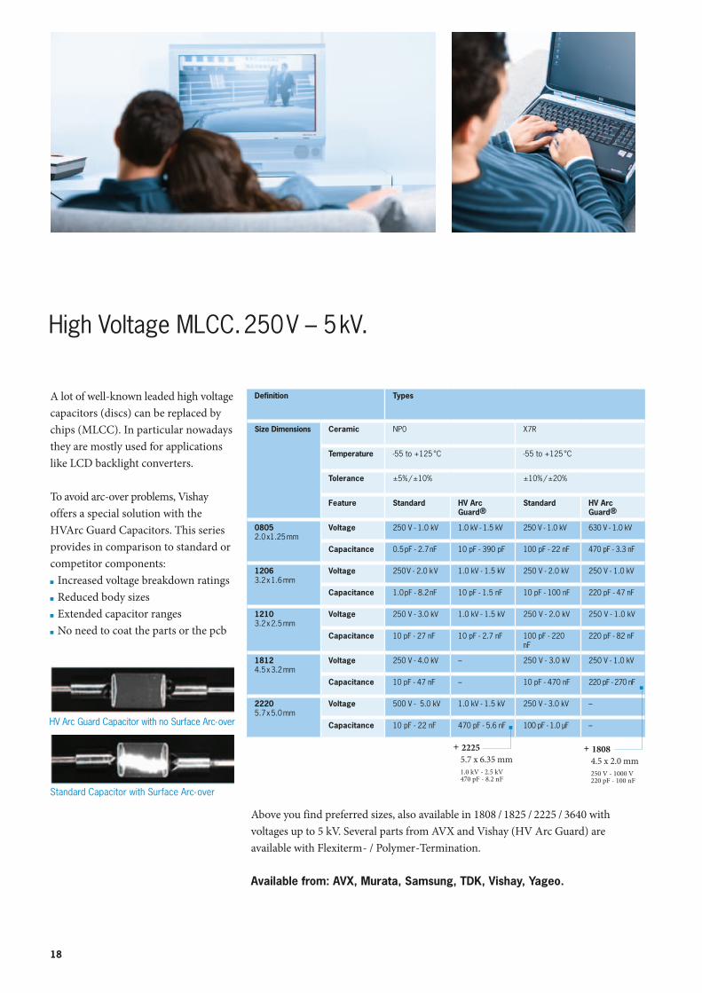
High Voltage MLCC. 250 V – 5 kV.
A lot of well-known leaded high voltage capacitors (discs) can be replaced by chips (MLCC). In particular nowadays they are mostly used for applications like LCD backlight converters.
To avoid arc-over problems, Vishay offers a special solution with the HVArc Guard Capacitors. This series provides in comparison to standard or competitor components: Increased voltage breakdown ratings Reduced body sizes Extended capacitor ranges No need to coat the parts or the pcb
Above you find preferred sizes, also available in 1808 / 1825 / 2225 / 3640 with voltages up to 5 kV. Several parts from AVX and Vishay (HV Arc Guard) are available with Flexiterm- / Polymer-Termination.
Available from: AVX, Murata, Samsung, TDK, Vishay, Yageo.
Standard Capacitor with Surface Arc-over
HV Arc Guard Capacitor with no Surface Arc-over
Definition Types
Size Dimensions Ceramic NP0 X7R
Temperature -55 to +125 °C -55 to +125 °C
Tolerance ±5% / ±10% ±10% / ±20%
Feature Standard HV Arc Guard®
Standard HV Arc Guard®
08052.0 x1.25 mm
Voltage 250 V - 1.0 kV 1.0 kV - 1.5 kV 250 V - 1.0 kV 630 V - 1.0 kV
Capacitance 0.5 pF - 2.7 nF 10 pF - 390 pF 100 pF - 22 nF 470 pF - 3.3 nF
12063.2 x 1.6 mm
Voltage 250 V - 2.0 k V 1.0 kV - 1.5 kV 250 V - 2.0 kV 250 V - 1.0 kV
Capacitance 1.0 pF - 8.2 nF 10 pF - 1.5 nF 10 pF - 100 nF 220 pF - 47 nF
12103.2 x 2.5 mm
Voltage 250 V - 3.0 kV 1.0 kV - 1.5 kV 250 V - 2.0 kV 250 V - 1.0 kV
Capacitance 10 pF - 27 nF 10 pF - 2.7 nF 100 pF - 220 nF
220 pF - 82 nF
18124.5 x 3.2 mm
Voltage 250 V - 4.0 kV – 250 V - 3.0 kV 250 V - 1.0 kV
Capacitance 10 pF - 47 nF – 10 pF - 470 nF 220 pF - 270 nF
2220 5.7 x 5.0 mm
Voltage 500 V - 5.0 kV 1.0 kV - 1.5 kV 250 V - 3.0 kV –
Capacitance 10 pF - 22 nF 470 pF - 5.6 nF 100 pF - 1.0 µF –
+ 18084.5 x 2.0 mm
250 V - 1000 V220 pF - 100 nF
+ 2225 5.7 x 6.35 mm 1.0 kV - 2.5 kV 470 pF - 8.2 nF
19
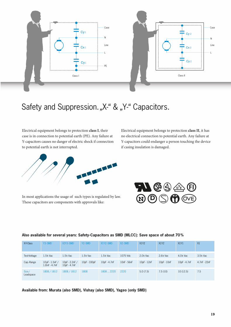
Safety and Suppression. „X-“ & „Y-“ Capacitors.
Electrical equipment belongs to protection class I, their case is in connection to potential earth (PE). Any failure at Y-capacitors causes no danger of electric shock if connection to potential earth is not interrupted.
Also available for several years: Safety-Capacitors as SMD (MLCC): Save space of about 70 %
Available from: Murata (also SMD), Vishay (also SMD), Yageo (only SMD)
Case
N
Line
L
PE
N
Line
L
Case
Class I Class II
1
1
1
2
2
2
Electrical equipment belongs to protection class II, it has no electrical connection to potential earth. Any failure at Y-capacitors could endanger a person touching the device if casing insulation is damaged.
In most applications the usage of such types is regulated by law.These capacitors are components with approvals like:
X-Y- Class Y3 - SMD X2Y3 - SMD Y2 - SMD X1Y2 - SMD X2 - SMD X1Y2 X1Y2 X1Y1 X1
Test-Voltage 1.5 k Vac 1.5 k Vac 1.5 k Vac 1.5 k Vac 1075 Vdc 2.0 k Vac 2.6 k Vac 4.0 k Vac 3.5 k Vac
Cap.-Range 10 pF - 1.5nF / 1.8 nF - 4.7nF
10pF - 2.2nF / 10pF - 4.7nF
10pF - 330pF 10pF - 4.7nF 10nF - 56nF 10pF - 12nF 10pF - 10nF 10pF - 4.7nF 4.7nF - 22nF
Size / Leadspace
1808 / 1812 1808 / 1812 1808 1808 … 2220 2220 5.0 (7.5) 7.5 (10) 10 (12.5) 7.5
20
Application examples are: Wireless systems
(e.g. keyless entry system, alarm system, etc.) Communication market
(Mobile Phones, Telephone Networks, etc.) Navigation systems TV systems (Satellite, Cable) Test & Measurement Equipment Radar systems GPS, GSM SMART Metering
Typical series from our suppliers are:
AVX: SLC, U, Accu-P, SQ (former AQ) and HQ Series
Murata: GJM, GQM, ERB, GMA Series
Vishay: VJ HiFreq RF Serie
Samsung: High Frequency Series
Yageo: Microwave
Series:
U, Accu-P, GJM, GQM,
ERB, VJ HiFreq RF, High
Frequency, Microwave
SQ, HQ SLC, GMA
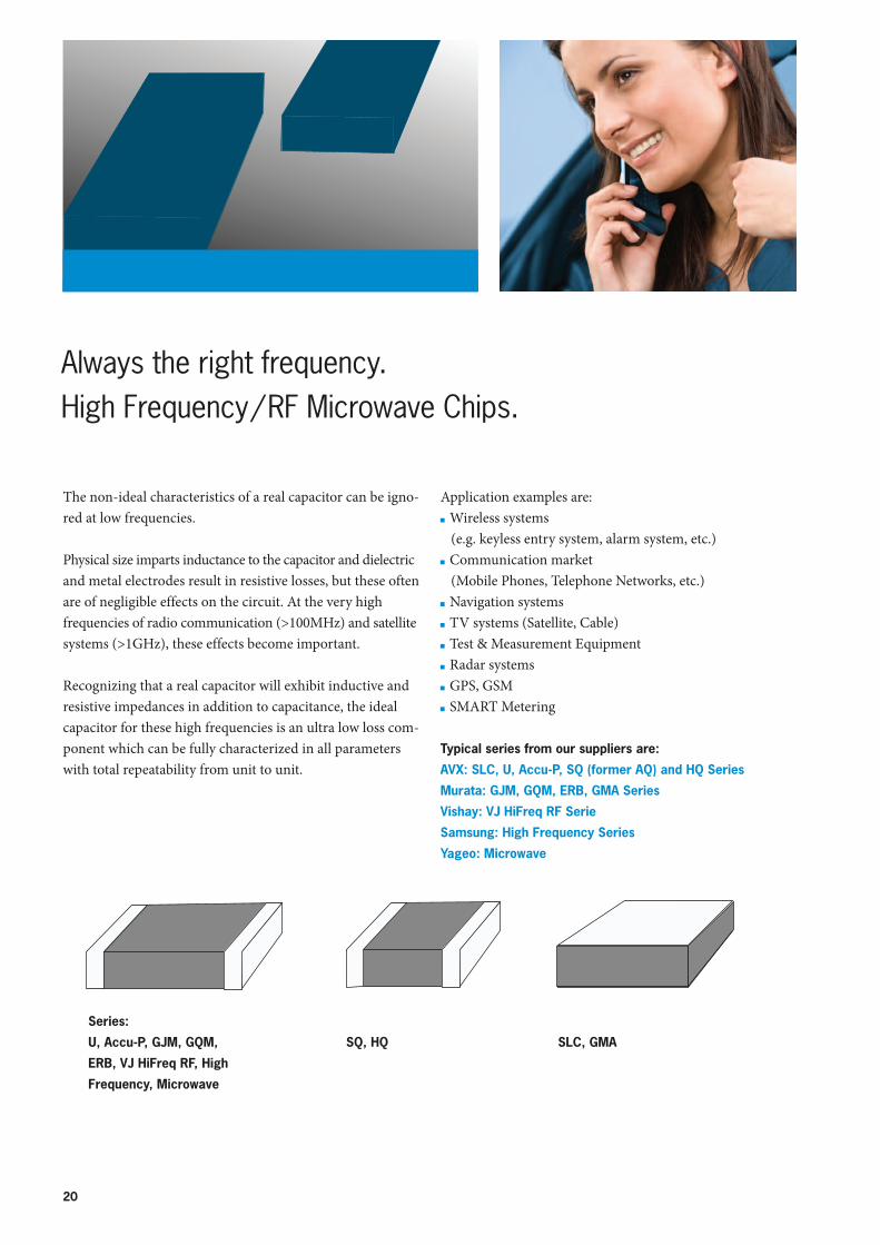
The non-ideal characteristics of a real capacitor can be igno-red at low frequencies.
Physical size imparts inductance to the capacitor and dielectric and metal electrodes result in resistive losses, but these often are of negligible effects on the circuit. At the very high frequencies of radio communication (>100MHz) and satellite systems (>1GHz), these effects become important.
Recognizing that a real capacitor will exhibit inductive and resistive impedances in addition to capacitance, the ideal capacitor for these high frequencies is an ultra low loss com-ponent which can be fully characterized in all parameters with total repeatability from unit to unit.
Always the right frequency. High Frequency / RF Microwave Chips.
21
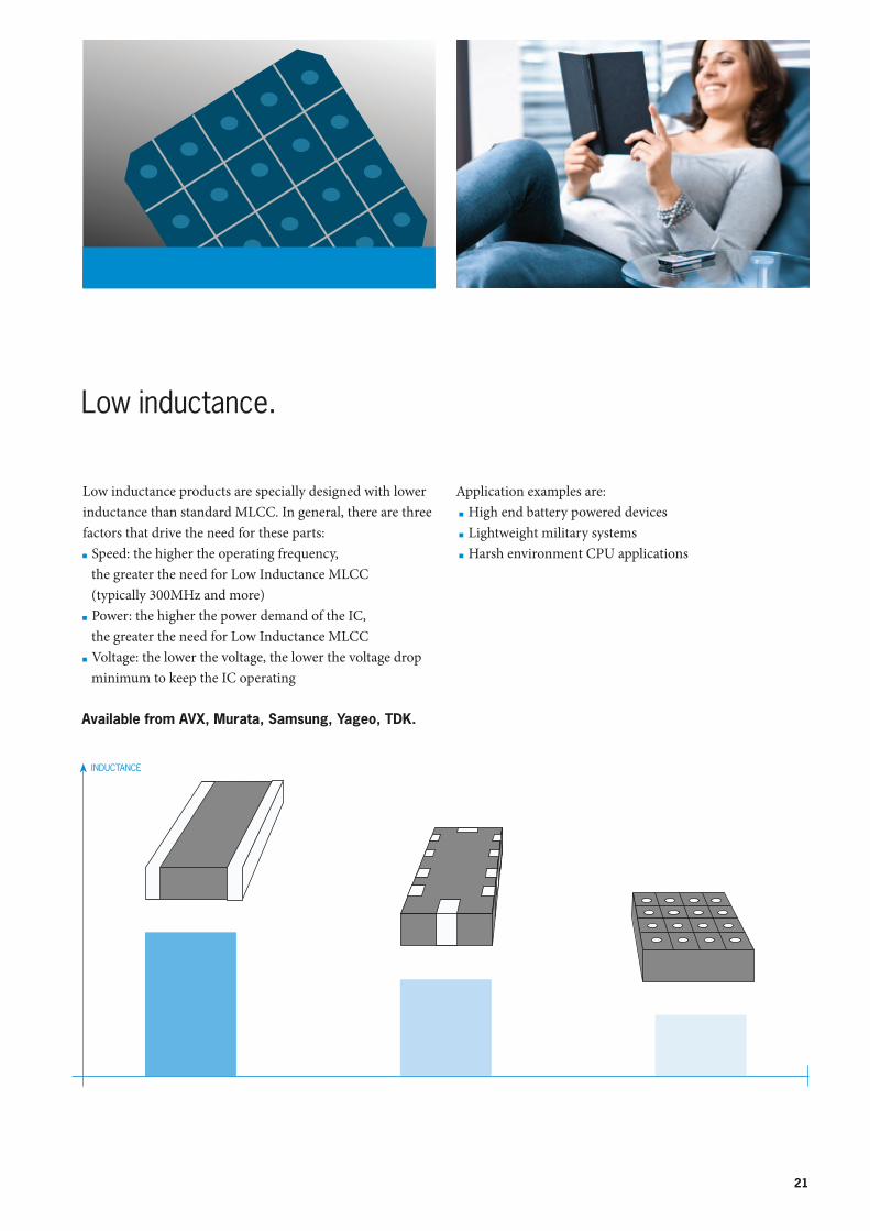
Application examples are: High end battery powered devices Lightweight military systems Harsh environment CPU applications
Low inductance products are specially designed with lower inductance than standard MLCC. In general, there are three factors that drive the need for these parts: Speed: the higher the operating frequency, the greater the need for Low Inductance MLCC (typically 300MHz and more)
Power: the higher the power demand of the IC, the greater the need for Low Inductance MLCC
Voltage: the lower the voltage, the lower the voltage drop minimum to keep the IC operating
Low inductance.
Available from AVX, Murata, Samsung, Yageo, TDK.
22
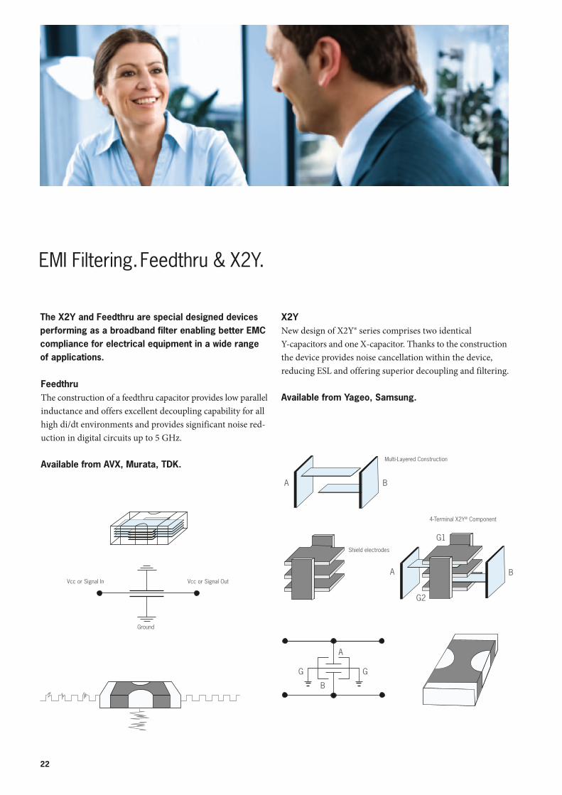
The X2Y and Feedthru are special designed devices performing as a broadband filter enabling better EMC compliance for electrical equipment in a wide range of applications.
FeedthruThe construction of a feedthru capacitor provides low parallel inductance and offers excellent decoupling capability for all high di/dt environments and provides significant noise red-uction in digital circuits up to 5 GHz.
Available from AVX, Murata, TDK.
X2YNew design of X2Y® series comprises two identical Y-capacitors and one X-capacitor. Thanks to the construction the device provides noise cancellation within the device, reducing ESL and offering superior decoupling and filtering.
Available from Yageo, Samsung.
Vcc or Signal In Vcc or Signal Out
Ground
EMI Filtering. Feedthru & X2Y.
Multi-Layered Construction
A B
A B
4-Terminal X2Y® Component
G1
G2
A
G G
B
Shield electrodes
23
Input Power Logic IC(Load)
V
t t
VV
t0 AC Noise
Power Logic IC
With Capacitor
MLCC Disccharge Current
Power Logic IC
Without Capacitor
Minimum Required VoltageCurrent Voltage
IC Shutdown
With CapacitorWithout Capacitor
High Freq. Signal Pass
Low Freq. Signal V outV in
Pass
Low HighFrequency
C
Low Freq. Signal Pass
High Freq. Signal V outV in
Pass
Low HighFrequency
L
C
High Pass FilterLow Pass Filter
Polarity High Cap Range Impedance / ESR characteristics
Temperature characteristics
High Voltage Resistance (overload)
Reliability
Electrolytic
Polymer
Ceramic
Film
Tantalum
Niobium
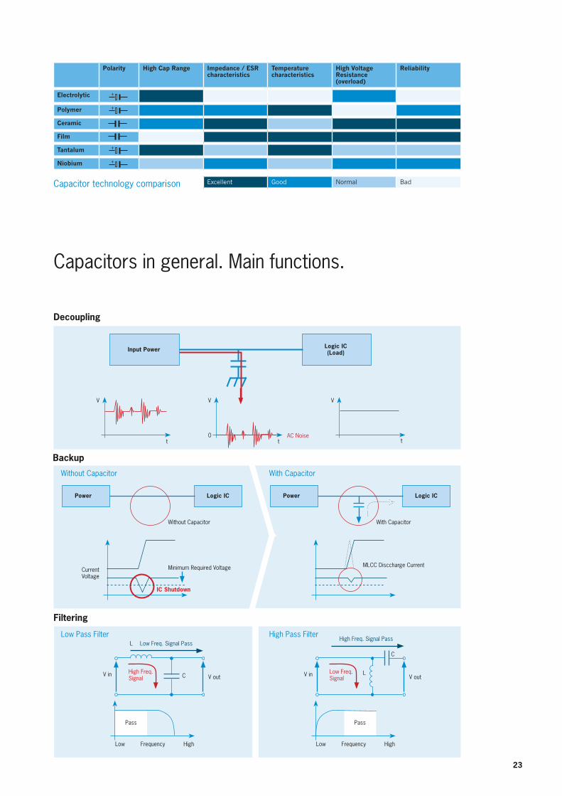
Excellent Good Normal BadCapacitor technology comparison
Capacitors in general. Main functions.
Decoupling
Backup
Filtering
L
+
+
+
+
M10
EN
G |
OIP
| S
peci
ficat
ions
subj
ect t
o ch
ange
with
out n
otic
e. Pl
ease
not
e, th
ere
coul
d be
som
e lim
itatio
ns fo
r som
e fr
anch
ised
prod
uct l
ines
in se
vera
l Eur
opea
n co
untr
ies.
For m
ore
info
rmat
ion,
ple
ase
cont
act o
ur sa
les t
eam
.
Germany – Headquarters
Rutronik Elektronische Bauelemente GmbH | Industriestraße 2 | 75228 Ispringen / PforzheimTel. +49 (0) 7231 801-0 | Fax +49 (0) 7231 82282 | E-Mail: [email protected] | www.rutronik.com
BerlinJustus-von-Liebig-Straße 712489 BerlinTel. +49 30 8 09 27 16-0Fax +49 30 8 09 27 16-16
DortmundZum Lonnenhohl 4044319 DortmundTel. +49 231 9 50 36-0Fax +49 231 9 50 36-31
DresdenRadeburger Straße 17201109 DresdenTel. +49 351 20 53 30-0Fax +49 351 20 53 30-10
ErfurtFlughafenstraße 499092 ErfurtTel. +49 361 2 28 36-30Fax +49 361 2 28 36-31
FrankfurtFrankfurter Straße 151 c63303 DreieichTel. +49 6103 2 70 03-0Fax +49 6103 2 70 03-20
FreiburgBasler Landstraße 879111 FreiburgTel. +49 761 61 16 77-0Fax +49 761 61 16 77-11
HamburgNeue Gröningerstraße 1020457 HamburgTel. +49 40 3 59 60 06-20Fax +49 40 3 59 60 06-50
MannheimAmselstraße 3368307 MannheimTel. +49 621 76 21 26-0Fax +49 621 76 21 26-17
MünchenLandsberger Straße 47881241 MünchenTel. +49 89 88 99 91-0Fax +49 89 88 99 91-19
NürnbergSüdwestpark 10/1290449 NürnbergTel. +49 911 6 88 68-0Fax +49 911 6 88 68-90
OstwestfalenBrockweg 13333332 GüterslohTel. +49 5241 2 32 71-0 Fax +49 5241 2 32 71-29
RatingenGothaer Straße 240880 RatingenTel. +49 2102 99 00-0Fax +49 2102 99 00-19
Photovoltaic & Lighting SolutionsRUSOL GmbH & Co. KGIndustriestraße 2, 75228 IspringenTel. +49 (0) 7231 801-2910Fax +49 (0) 7231 [email protected]
PortugalRutronik ElektronischeBauelemente GmbHAv. General Humberto DelgadoPorta 8, 1ºAndar, Sala R4760-012 V. N. FamalicãoTel. +351 252 3 12-336
RomaniaRutronik ElektronischeBauelemente GmbHGrigore T. Popa Strasse nr. 81, etage 8300291 TimişoaraTel. +40 25 64 01 240
BucureştiTel. +40 314 25 38 39
RussiaRutronikBeteiligungsgesellschaft mbHLeningradskoje Chaussee 16Building 3, Office 403125171 MoscowTel. +7 495 7 86 28 02
SerbiaRutronik ElektronischeBauelemente GmbHYUBC Bul. Mihajla Pupina 10z/IV, 11070 BeogradTel. +381 11 311 33 66-3
SlovakiaRutronik ElektronischeBauelemente GmbH, o.z.Lazovná 1197401 Banská BystricaTel. +421 48 4 72 23-00
SloveniaRutronik ElektronischeBauelemente GmbHMotnica 5, 1236 TrzinTel. +386 1 5 61 09 80
SpainRutronik España S.L.BarcelonaC/ Marqués de Sentmenat 54 - 58, 3a Planta - 1o, 08029 BarcelonaTel. +34 93 4 44 24 12
FranceRutronik S.A.S6, Mail de l’Europe78170 La Celle St CloudTel. +33 1 30 08 33 [email protected]. +33 5 57 26 40 00GrenobleTel. +33 4 76 61 00 90Le MansTel. +33 2 43 78 16 97LyonTel. +33 4 72 76 80 00PoitiersTel. +33 5 49 52 88 88RennesTel. +33 2 23 45 14 40
StrasbourgTel. +33 3 88 78 12 12
HungaryRutronik Magyarország Kft.Fehérvári út 89-95, 1119 BudapestTel. +36 1 371 06 66
ItalyRutronik Italia S.r.l.21, Via CalderaCentro Direzionale S.Siro20153 Milano (MI)Tel. +39 02 4 09 [email protected]
AnconaVia 1° Maggio, 150/B60131 Ancona (AN)Tel. +39 071 2 91 62 18
BolognaVia Gazzani, 8/2 - Z.I. Bargellino40012 Calderara di Reno (BO)Tel. +39 051 6 46 32 00
FlorenceVia V. Emanuele, 3350041 Calenzano (FI)Tel. +39 055 8 82 73 32
NaplesVia Arcora, 110, Palazzo Gecos80013 Casalnuovo di Napoli (NA)Tel. +39 081 5 22 87 09
AustriaRutronik ElektronischeBauelemente Ges. m. b. H.Durisolstraße 14600 WelsTel. +43 7242 4 49 01
BelgiumRutronik ElektronischeBauelemente GmbHKeppekouter 1Ninovesteenweg 1989320 Erembodegem-AalstTel. +32 53 60 65 90
BulgariaRutronik ElektronischeBauelemente GmbHZheko Voyvoda street no. 51756 SofiaTel. +359 2 9 74 86-46
Czech RepublicRutronik ElektronischeBauelemente CZ s.r.o.
BrnoSlavičkova 1a, 63800 BrnoTel. +420 5 4 54 24-681
PraguePapírenská 1160 00 PrahaTel. +420 2 33 34 31 20
DenmarkRutronik ElektronischeBauelemente GmbHHerstedøstervej 27-292620 AlbertslundTel. +45 7020 19 63
EstoniaRutronik ElektronischeBauelemente GmbHVaksali 17A, 50410 TartuTel. +372 7370951
FinlandRutronik ElektronischeBauelemente GmbHKirkonkyläntie 300700 HelsinkiTel. +358 9 32 91 22 00
MadridCtra. Canillas 134 - 1a Planta - 9B28043 MadridTel. +34 91 3 00 55 28San SebastiánPo Ubarburu, 71 - 1oE 20115 AstigarragaTel. +34 943 40 45 28
SwedenRutronik Nordic ABKista Science TowerFärögatan 33, 16451 KistaTel. +46 8 50 55 49 00
SwitzerlandRutronik ElektronischeBauelemente AG
VolketswilHölzliwisenstr. 5, 8604 VolketswilTel. +41 44 9 47 37 37
Yverdon-les-BainsRue Galilée 15, 1400 Yverdon-les-BainsTel. +41 24 4 23 91 40
TurkeyPartner of Rutronik group:Elektro Elektronik San. Tic. A.S.Burhaniye Mah. BahcelerSokak No:10Beylerbeyi 34676 Uskudar/IstanbulTel. +90 216 557 67 00
United Kingdom & IrelandRutronik UK Ltd.Deakins Business Park,Blackburn Road, EgertonBL7 9RP Bolton, LancashireTel. +44 1204 60 22 00
PaduaVia Savelli, 6235129 Padova (PD)Tel. +39 049 8 69 78 00
RomeVia Del Maggiolino, 12500155 Roma (RO)Tel. +39 06 228 782-1
TurinStrada Torino, 43/45Europalace10043 Orbassano (TO)Tel. +39 011 9 02 20 00
LithuaniaRutronik ElektronischeBauelemente GmbHRaudondvario pl.7647182 KaunasTel. +370 37 26 17 80
NorwayRutronik ElektronischeBauelemente GmbHOlav Helsets vei 6 0694 OsloTel. +47 22 76 79 20
NetherlandsRutronik ElektronischeBauelemente GmbHPapland 4a 4206 CL GorinchemTel. +31 183 64 60-50
PolandRutronik Polska Sp. z o.o.ul. Bojkowska 37 44-101 GliwiceTel. +48 32 4 61 20 00
Gdyniaul. Batorego 28-3281-366 GdyniaTel. +48 58 7 83 20-20
Warsawul. Patriotów 11004-844 WarszawaTel. +48 22 3 32 73-70
International branches:
European branches:
ShanghaiRoom 621, Building 2, No. 11 Lane 225, Jin Xiang RoadPudong New District, ShanghaiTel. +86 216 8869 910
Hong KongRutronik Electronics Asia HK Ltd.
Hong Kong51/F, Hopewell Centre 183 Queens Road East Wan Chai Tel. +852 3602 3135
MexicoRutronik Mexico S.A. DE C.V.
Ecuador Nº 4Lomas de Queretaro76190 QueretaroTel. +52 442 242 5361
ChengduRoom no. 407, 4FNo. 31 Zong Fu Street610016 ChengduTel. +86 28 8651 2214
TaiwanRutronik Electronics Asia HK Ltd.
Taipei (Taiwan branch)13F.-2, No.27, Lane 169, Kangning St., Xizhi District221 New Taipei CityTel. +886 (2) 2692 7041
ChinaRutronik Electronics SZ Ltd.
ShenzhenRoom 3E, Tong Tai BldgBagua Road 4th Futian District, ShenzhenTel. +86 755 8240 7106


![Product Selection Further Information - Rutronik...Tol. Pitch [mm] Vishay PN Y1 220 ± 10% 10.0 VY1221K31Y5SG6UV0 470 ± 20% 10.0 VY1471M31Y5UG6UV0 1,000 ± 20% 10.0 VY1102M35Y5UG6UV0](https://img.pdfslide.us/doc/110x75/5f2ae92601a9a934ca7965ee/product-selection-further-information-rutronik-tol-pitch-mm-vishay-pn-y1.jpg)