Embed Size (px)
Citation preview
Aerospace Fasteners
G784HYDRO-SHIFT CHERRYLOCK® RIVETER
NSN 5130-00-935-4681
MA
NU
AL
Instruction ManualPass on to user to read and keep for reference
Part No. 195A137
TABLE OF CONTENTS
Description . . . . . . . . . . . . . . . . . . . . . . . . . . . . . . . . . . . . . . . . . . . . . . . . . . . . . . . . . . . . . . . . . . . . . . .1
Specifications for G784 . . . . . . . . . . . . . . . . . . . . . . . . . . . . . . . . . . . . . . . . . . . . . . . . . . . . . . . . . . . . . .1
Safety Warnings . . . . . . . . . . . . . . . . . . . . . . . . . . . . . . . . . . . . . . . . . . . . . . . . . . . . . . . . . . . . . . . . . . .2
How to Use the G784 . . . . . . . . . . . . . . . . . . . . . . . . . . . . . . . . . . . . . . . . . . . . . . . . . . . . . . . . . . . . . . .3
Maintenance and Repair . . . . . . . . . . . . . . . . . . . . . . . . . . . . . . . . . . . . . . . . . . . . . . . . . . . . . . . . . . . . .3
Fill and Bleed Instructions . . . . . . . . . . . . . . . . . . . . . . . . . . . . . . . . . . . . . . . . . . . . . . . . . . . . . . . . . . . .4
Trouble Shooting . . . . . . . . . . . . . . . . . . . . . . . . . . . . . . . . . . . . . . . . . . . . . . . . . . . . . . . . . . . . . . . . . . .4
Overhaul . . . . . . . . . . . . . . . . . . . . . . . . . . . . . . . . . . . . . . . . . . . . . . . . . . . . . . . . . . . . . . . . . . . . . . . . .5
Air Valve . . . . . . . . . . . . . . . . . . . . . . . . . . . . . . . . . . . . . . . . . . . . . . . . . . . . . . . . . . . . . . . . . . . .5
Head Sub-Assembly . . . . . . . . . . . . . . . . . . . . . . . . . . . . . . . . . . . . . . . . . . . . . . . . . . . . . . . . .6-7
Handle Sub-Assembly . . . . . . . . . . . . . . . . . . . . . . . . . . . . . . . . . . . . . . . . . . . . . . . . . . . . . . . . .8
Adjustment Instructions . . . . . . . . . . . . . . . . . . . . . . . . . . . . . . . . . . . . . . . . . . . . . . . . . . . . . . . . . . . . . .9
Shift Point Setting . . . . . . . . . . . . . . . . . . . . . . . . . . . . . . . . . . . . . . . . . . . . . . . . . . . . . . . . . . . . .9
Shift Piston Check . . . . . . . . . . . . . . . . . . . . . . . . . . . . . . . . . . . . . . . . . . . . . . . . . . . . . . . . . . . .9
Pulling Heads . . . . . . . . . . . . . . . . . . . . . . . . . . . . . . . . . . . . . . . . . . . . . . . . . . . . . . . . . . . . . . . . . . . .10
Tool Capacity Charts . . . . . . . . . . . . . . . . . . . . . . . . . . . . . . . . . . . . . . . . . . . . . . . . . . . . . . . . .10
Installing H681 Series Pulling Heads on Riveter . . . . . . . . . . . . . . . . . . . . . . . . . . . . . . . . . . . . .10
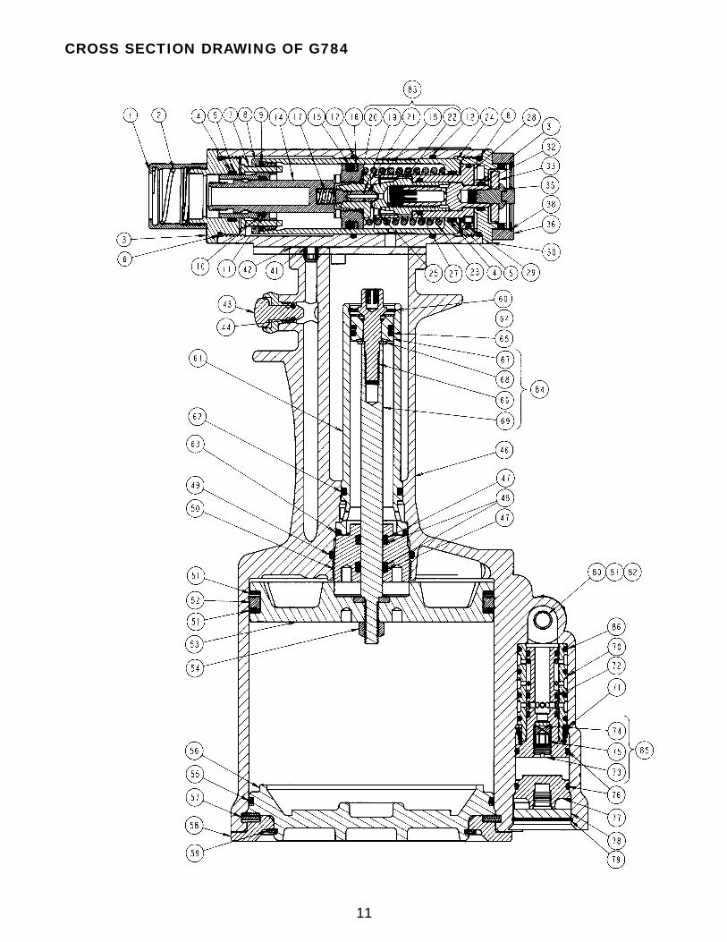
Cross Section Drawing of G784 . . . . . . . . . . . . . . . . . . . . . . . . . . . . . . . . . . . . . . . . . . . . . . . . . . . . . .11
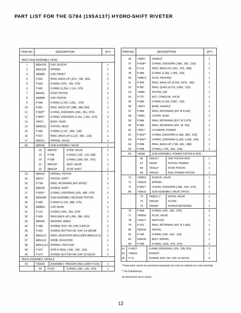
Parts List for G784 Riveter . . . . . . . . . . . . . . . . . . . . . . . . . . . . . . . . . . . . . . . . . . . . . . . . . . . . . . . . . .12
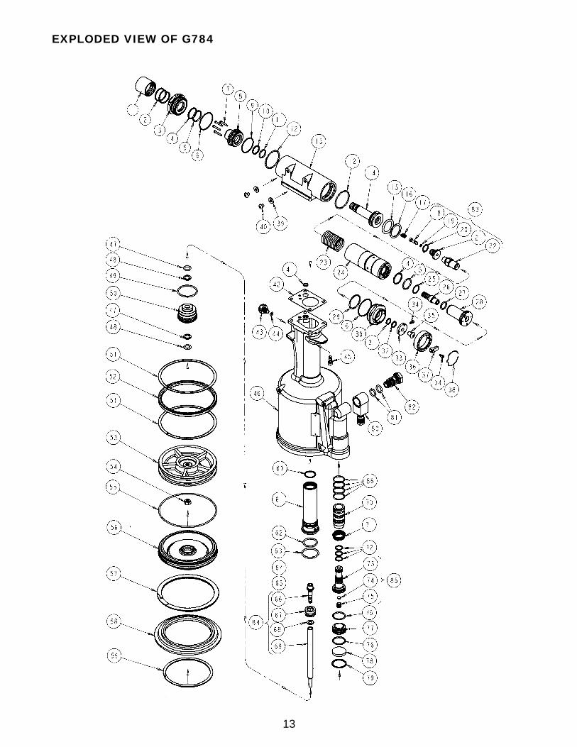
Exploded View of G784 . . . . . . . . . . . . . . . . . . . . . . . . . . . . . . . . . . . . . . . . . . . . . . . . . . . . . . . . . . . . .13
Declaration of Conformity . . . . . . . . . . . . . . . . . . . . . . . . . . . . . . . . . . . . . . . . . . . . . . . . . . . .Back Cover
THE G784 HYDRO-SHIFT RIVETER
1
Textron Aerospace Fasteners’ (TAF) policy is one of continuousdevelopment. Specifications shown in this document may be sub-ject to change which may be introduced after publication. For thelatest information always consult TAF.
➤
➤
➤
➤➤
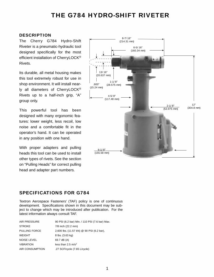
4-5/8"(117.48 mm)
8-7/16"(214.31 mm)
➤
➤
12"(304.8 mm)
6-1/8"(155.58 mm)
➤
➤
6-5/16"(160.34 mm) ➤
➤
➤ ➤
➤
➤
➤ ➤
13/16"(20.637 mm)
➤
1-1/8"(28.575 mm)
2-1/8"(53.975 mm)
.600"(15.24 mm)
DESCRIPTIONThe Cherry G784 Hydro-Shift
Riveter is a pneumatic-hydraulic tool
designed specifically for the most
efficient installation of CherryLOCK®
Rivets.
Its durable, all metal housing makes
this tool extremely robust for use in
shop environment. It will install near-
ly all diameters of CherryLOCK®
Rivets up to a half-inch grip, “A”
group only.
This powerful tool has been
designed with many ergonomic fea-
tures: lower weight, less recoil, low
noise and a comfortable fit in the
operator’s hand. It can be operated
in any position with one hand.
With proper adapters and pulling
heads this tool can be used to install
other types of rivets. See the section
on “Pulling Heads” for correct pulling
head and adapter part numbers.
AIR PRESSURE 90 PSI (6.2 bar) Min. / 110 PSI (7.6 bar) Max.
STROKE 7/8 inch (22.2 mm)
PULLING FORCE 2,600 lbs. (11.57 kN) @ 90 PSI (6.2 bar),
WEIGHT 8 lbs. (3.63 kg)
NOISE LEVEL 69.7 dB (A)
VIBRATION less than 2.5 m/s2
AIR CONSUMPTION .27 SCF/cycle (7.65 L/cycle)
SPECIFICATIONS FOR G784
THE G784 HYDRO-SHIFT RIVETER
2
SAFETY WARNINGS• Approved eye protection should be worn when operating, repairing, or overhauling this tool.
• Do not use beyond the design intent.
• Do not use substitute components for repair.
• Any modification to the tool, pulling heads, accessories or any component supplied by TAF/Cherry, or their representatives, shall be the customer’s entire responsibility. TAF/Cherry will be pleased to advise on any proposed modification.
• The tool must be maintained in a safe working condition at all times and examined at regular intervals for damage.
• Before disassembling the tool for repair, refer to the maintenance instructions. All repairs shall be undertaken only by personnel trained in TAF/Cherry installation tools. Contact TAF/Cherry with your training requirement.
• Always disconnect the air line from the tool inlet before attempting to service, adjust, fit or remove any accessory.
• Do not operate the tool when it is directed at any person.
• Ensure that the vent holes do not become blocked or covered and that air line hoses are always in good condition.
• Excessive contact with the hydraulic oil should be avoided to minimize the possibility of rashes. Care should be takento wash thoroughly.
• Operating air pressure should not exceed 110 psi (7.6 bar).
• Do not operate the tool without the pulling head in place.
• Do not operate the tool unless the handle base (56) is fully secured by the retaining ring (57).
• All retaining rings, screwed end caps, air fittings, trigger valves and pulling heads should be attached securely and examined at the end of each working shift.
• Do not pull rivet in the air.
• The precautions to be used when using this tool must be explained by the customer to all operators. Any questionregarding the correct operation of the tool and operator safety should be directed to TAF/Cherry.
• Do not pound on the rear of the tool head to force rivets into holes as this will damage the tool.
• Do not depress the trigger while disconnecting the air bleeder and replacing the cap screws (40) when bleeding the tool.
• Do not release the trigger after installing a CherryLOCK® rivet until the tool is positioned away from the structure orpersonnel. Upon release of the trigger the stem will eject from the front of the pulling head with moderate force.
3
DEXRON III OIL SAFETY DATAFIRST AID
Skin: Wash thoroughly with soap and water as soon as possible. Casual contact requires no immediate attention.If irritation develops, consult a physician.
Ingestion: Seek medical attention immediately. DO NOT INDUCE VOMITING.
Eyes: Flush with copious amounts of water. If irritation develops, consult a physician.
Inhalation: No significant adverse health effects are expected to occur on short term exposure. Remove from contaminated area.Apply artificial respiration if needed. If unconscious, consult physician.
FIRE
Suitable extinguishing media: CO2, dry powder, foam or water fog. DO NOT use water jets.
ENVIRONMENT
Waste Disposal: In accordance with local, state and federal regulations.
Spillage: Prevent entry into drains, sewers and water courses. Soak up with diatomaceous earth or other inert material. Store in appropriate container for disposal.
HANDLING
Eye protection required. Protective gloves recommended. Chemically resistant boots and apron recommended. Use in well ventilated area.
COMBUSTIBILITY
Slightly combustible when heated above flash point. Will release flammable vapor which can burn in open or be explosive in confined spaces if exposed to source of ignition.
STORAGE
Avoid storage near open flame or other sources of ignition.
PROPERTIES
Specific gravity 0.863
Weight per gallon 7.18 lbs.
Open flash point >200°C (392°F)
Use automatic transmission fluid Type “A” (no substitutes). Textron Aerospace Fasteners recommends using ATF, Dexron III oil.
HOW TO USE THE G784Select the proper pulling head and attach it securely to the G784. For proper installation of the pulling head, see thepulling head tool sheet. Connect the air line to the tool.
Insert the rivet into the application. Place the pulling head over the rivet stem, pushing the tool until the pulling head isin contact with the rivet head. This will ensure full engagement between the jaws and the rivet stem. When pushingdown on the rivet stem, make certain the tool is perpendicular to the application.
After activating the trigger, the tool will cycle, installing the rivet. After the stem breaks, point the tool toward an appro-priate receptacle and release the trigger. The stem will eject from the front of the tool with a moderate force.
MAINTENANCE AND REPAIRThe G784 has been manufactured to give maximum service with minimum care. In order that this may be accom-plished, the following recommendations should be followed:
1. The hydraulic system should be full of oil and free from air at all times.
2. Keep excessive moisture and dirt out of air supply to prevent wear of air valve, air cylinder and air piston.
3. Tool should be routinely inspected for oil leaks. Oil leaking around screws (40) indicates that a screw is loose or a Stat-O-Seal (39) needs replacing.
4
1. Check the air line for correct pressure at the tool. It must be90 to 110 PSI (6.2 to 7.6 bar).
2. Check for oil leakage:• Oil leaking around the cap screws (40) in the head
indicates that a screw is loose or a Stat-O-Seal (39) needs replacing.
• If oil should leak through the by-pass hole at the base ofthe handle (46) the O-ring (63) is worn or damaged.
• Oil leaking from the front of the head (13) indicates that O-rings (5 and 11) are worn or damaged; replace.
3. Check for excessive air leakage from the air valve:• If spring (71) is broken or dislodged, air will bleed
directly through the bottom of the air valve and the headpiston retreats to its full stroke without returning. See airvalve instructions on Page 5.
• If O-ring (76) on valve plug (77) is worn or damaged, replace.
• If O-rings (72) on valve spool sub-assembly (85) are worn or damaged, replace.
4. Check movement of the head piston (14). If it does not movefreely or is slow in operation:
• Valve stem (18) may be held off its seat (21) by contaminants, allowing oil to by-pass. Drain gun, flush thoroughly and refill with fresh oil.
• O-rings (65) and (15) may be damaged and require replacement.
• Head piston (14) may be mechanically locked due to damaged parts.
• Muffler (78) or air filter (74) inside valve spool sub-assembly (85) may be plugged with dirt. Clean themthoroughly with normal solvent and back-blow with compressed air.
• Hole in metering screw (75) in valve spool sub-assembly(85) may be blocked or damaged. Hole diameter shouldbe .028" (.7112 mm). Clear and size or replace valve spool sub-assembly (85). Metering screw (75), filter (74)and valve spool (73) are not sold separately.
5. Check movement of shift piston (24). If it does not move freely:• Small holes in screen in release piston sub-assembly
(28) may be plugged preventing oil flow. Drain gun, flushthoroughly and refill with fresh oil. See Fill and Bleed Instructions.
• Hole through shift valve (18) may be plugged by contaminants. Drain gun, flush thoroughly and refill withfresh oil.
• Pulling head components need maintenance.Disassemble the pulling head, clean and replace worn parts. Reassemble following pulling head instructions on page 10.
TROUBLESHOOTING
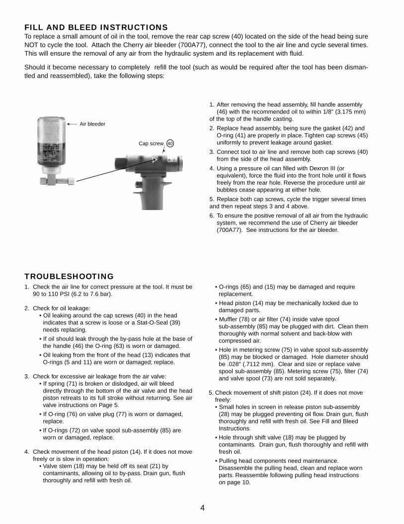
FILL AND BLEED INSTRUCTIONSTo replace a small amount of oil in the tool, remove the rear cap screw (40) located on the side of the head being sureNOT to cycle the tool. Attach the Cherry air bleeder (700A77), connect the tool to the air line and cycle several times.This will ensure the removal of any air from the hydraulic system and its replacement with fluid.
Should it become necessary to completely refill the tool (such as would be required after the tool has been disman-tled and reassembled), take the following steps:
Air bleeder
Cap screw
➤
➤
40
1. After removing the head assembly, fill handle assembly (46) with the recommended oil to within 1/8" (3.175 mm)
of the top of the handle casting.
2. Replace head assembly, being sure the gasket (42) and O-ring (41) are properly in place. Tighten cap screws (45)uniformly to prevent leakage around gasket.
3. Connect tool to air line and remove both cap screws (40)from the side of the head assembly.
4. Using a pressure oil can filled with Dexron III (or equivalent), force the fluid into the front hole until it flows freely from the rear hole. Reverse the procedure until air bubbles cease appearing at either hole.
5. Replace both cap screws, cycle the trigger several times and then repeat steps 3 and 4 above.
6. To ensure the positive removal of all air from the hydraulicsystem, we recommend the use of Cherry air bleeder (700A77). See instructions for the air bleeder.
5
AIR VALVE• To disassemble, first disconnect tool from its air source.
• Remove retaining ring (79) and muffler (78). Insert a valve plug extractor (P1178) or 5/16-18 threaded rod or
bolt into end of valve plug (77) and pull it out. Using the same procedures, pull out valve spool sub-assembly
(85).
• Muffler (76) inside valve spool sub-assembly (85) may be plugged with dirt. Clean it thoroughly with normal
solvent and back-blow with compressed air.
NOTE: It should never be necessary to remove valve sleeve (70) unless the ports in the sleeve have become
plugged from contaminated air. The O-rings on this sleeve are static and hence do not wear.
• If it is suspected that the ports are plugged, use needle nose pliers to grasp end of spring (71), turn clockwise
and pull to dislodge from groove in handle.
• With spring removed, valve sleeve (70) can be pulled out using the valve sleeve removal tool (837B740).
To re-assemble, reverse the above procedures being certain that all O-rings are properly lubricated. To avoid damag-
ing the O-rings (72), carefully install sleeve (70) with your fingers. Gently push and wiggle sleeve to allow O-rings to
slip past inner ports. Spring (71) is best installed using a valve spring installation tool (836B740) to push the large diam-
eter coil into the groove. This requires care as the tool will not operate if this spring is not anchored firmly.
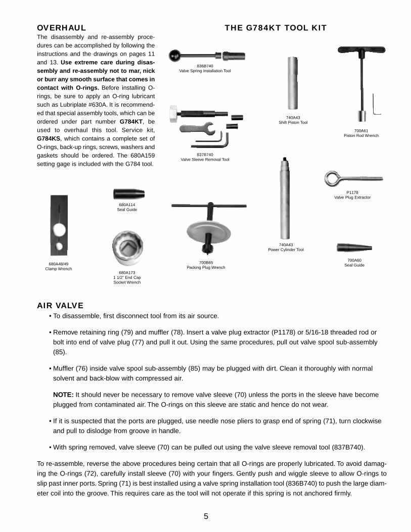
OVERHAULThe disassembly and re-assembly proce-dures can be accomplished by following theinstructions and the drawings on pages 11and 13. Use extreme care during disas-sembly and re-assembly not to mar, nickor burr any smooth surface that comes incontact with O-rings. Before installing O-rings, be sure to apply an O-ring lubricantsuch as Lubriplate #630A. It is recommend-ed that special assembly tools, which can beordered under part number G784KT, beused to overhaul this tool. Service kit,G784KS, which contains a complete set ofO-rings, back-up rings, screws, washers andgaskets should be ordered. The 680A159setting gage is included with the G784 tool.
THE G784KT TOOL KIT
836B740Valve Spring Installation Tool
837B740Valve Sleeve Removal Tool
700B65Packing Plug Wrench
740A43Power Cylinder Tool
P1178Valve Plug Extractor
700A60Seal Guide
700A61Piston Rod Wrench
680A1731 1/2" End Cap Socket Wrench
680A114Seal Guide
680A48/49Clamp Wrench
740A43Shift Piston Tool
6
HEAD SUB-ASSEMBLY• Always remove the complete pulling head from the tool before attempting disassembly of the head assembly.
Disconnect tool from air source.
• Remove the four socket head cap screws (45). Lift head sub-assembly from the handle (46). Remove O-ring (41) and gasket (42). Empty the oil into a container by pouring from the handle.
• Remove cap screws (40) and Stat-O-Seals (39), and drain the hydraulic system. Dispose of the oil according to environmental regulations.
• Select a work table with a good vise. Place the head cylinder (13) in the vise with the front end cap of the head cylinder (13) up. Tighten the vise securely.
• Use the end cap socket wrench (680A173) and improvise a handle extension to 26"-28". The end caps on the head cylinder have thin hex flats and a standard socket will slip over the hex corners. The end caps on the head cylinder (13) are factory tightened with a torque wrench from 150 to 180 ft.-lbs. (203 to 244 N-m). The
break away torque will be high - approximately 180 ft.-lbs. (244 N-m) or slightly higher.
• Remove the front end cap (3) from the head cylinder (13). Then remove the four piston stops (7).
• Place the head cylinder (13) in the vise so that the rear end cap (30) can be removed from the head cylinder (13).
• Remove the plastic adjuster knob (37) by first removing the socket head cap screw (34) with a 3/32 hex key.
• Remove the adjuster ring (36) by removing the other socket head cap screw (34).
• Remove the rear end cap (30) from the head cylinder (13). The following parts will come out with it: socket head cap screw (35), index washer (33), release piston sub-assembly (28), shift screw (26), shift stop (22), andretaining ring (25). The screen on the release piston sub-assembly (28) may need cleaning.
• Push on the head piston (14). This will allow the shift piston sub-assembly to be removed from the rear of the head cylinder (13). The shift piston sub-assembly includes the following parts: piston cap (8), O-ring (9), back-up ring (10), O-ring (11), head piston (14), O-ring (15), back-up ring (16), valve spring (17), valve stem (18), O-rings (19 and 20), valve seat (21), shift stop (22), piston spring (23), and shift piston (24).
NOTE: Valve parts (18), (21) and (22) are matched parts and must be kept together or replaced as a complete unit by purchasing valve sub-assembly (680A40).
To disassemble the Shift Piston Sub-Assembly:
• Insert the shift piston sub-assembly into the large hole of clamp wrench (680A48/49), locating on a polished surface. Tighten the wrench’s cap screws securely so that the shift piston sub-assembly cannot turn in the clamp.
• Place the clamp wrench (680A48/49) in a vise with the shift piston sub-assembly upward.
• Use the second clamp wrench (680A48/49) on the piston cap (8). Place the small hole of the clamp wrench overthe piston cap (8) and tighten the cap screws on the wrench to prevent slipping.
• Place shift piston tool (700A63) over the threads and against the shoulder of the head piston (14).
• When removing the piston cap (8), push firmly on the shift piston tool (700A63) to depress the head piston (14)and overcome the tension created by the piston spring (23). Caution should be used as spring will pop outif precautionary measure are not taken.
• Remove the valve seat (21) with an 11/16" wrench. Remove the valve stem (18) by pushing from front of the valveseat (21). Remove the valve spring (17).
7
To disassemble the End Cap Sub-Assembly
• Using a 5/32 hex key, turn the button head cap screw (35) counterclockwise until it stops.
• Remove retaining ring (25) inside of release piston sub-assembly (28) with a sharp or pointed instrument.
• After retaining ring (25) is removed, use a 5/32 hex key in the same button head cap screw (35). Turn clockwiseuntil the shift stop (22) can be removed from the release piston sub-assembly (28).
• Place a 3/16 hex key in the end of the shift screw (26) and a 5/32 hex key in the button head cap screw (35).Apply a force on both hex keys until you loosen the button head cap screw (35) which is threaded into the end of the shift screw (26).
• Remove the button head cap screw (35) and the index washer (33).
• Push the shift screw (26) out of the release piston sub-assembly (28). It may be held slightly by O-ring (27).
• Remove the release piston sub-assembly (28) from the rear cap (30) and check the filter in the release piston sub-assembly for debris. If the filter is clogged, back-blow with compressed air.
Upon re-assembly, reverse the above procedures. Be sure to install O-rings and back-up rings using seal guides, whereappropriate, to avoid cutting them. Always lubricate all O-rings. Just before placing the head sub-assembly onto thehandle, see Fill and Bleed Instructions. Also make sure the O-rings (41) and the gasket (42) on the top of the handleare properly oriented.
• Insert release piston sub-assembly (28) into rear cap (30), making sure index pin in release piston sub-assembly (28) drops into recess in rear cap (30).
• Insert shift screw (26) into the release piston sub-assembly (28). Slip index washer (33) onto adjusting screw (35). Engage threads of button head cap screw (35) with shift screw (26) and firmly tighten. Then turn button head cap screw (35) counter clockwise to retract shift stop (22) fully into release piston (28). Ensure that the hexof the shift stop (22) is aligned with the hex of the release piston sub-assembly (28).
• Install piston cap (8) onto head piston (14), threading seal guide tool (680A114) on head piston (14) to avoid damaging the O-rings as piston cap (8) is threaded into place.
• Hold shift piston (24) using the large hole in clamp wrench (680A48/49), being careful not to mar the smoothly ground surfaces of the piston. Insert piston spring (23), and while compressing it, turn piston cap sub-assembly(8 and 14) into place with clamp wrench (680A48/49) and firmly tighten.
• Insert shift piston sub-assembly (24) into front of head cylinder (13) and thread on rear cap (30). Insert the four piston stops (7), choosing every other hole. Thread on front end cap (3). Place head assembly in smooth jawed vise, clamping on hex of rear cap (30), with front end cap (3) upward. Using the end cap socket wrench
(680A173) and a handle extension, tighten front end cap (3) to 150-180 ft.-lbs. (203 to 244 N-m) torque.
• Replace adjuster ring (36), socket head cap screw (34), adjuster knob (37), and then the other socket head capscrew (34) onto the back of the rear cap (30).
• Just before placing the head sub-assembly onto the handle, see Fill and Bleed Instructions. Also make sure to place O-rings (41) and gasket (42) on the top of the handle, and that they are properly oriented.
• Tighten the four socket head cap screws (45) and one socket head cap screw (90) uniformly to prevent leakagearound the gasket.
• Purge system of air using Cherry air bleeder (700A77) according to Fill and Bleed instructions.
8
HANDLE SUB-ASSEMBLYFor complete disassembly, disconnect tool from air line and use the following procedures.
• Holding tool upright, remove four socket head cap screws (45). Lift head sub-assembly from handle (46) and setaside O-ring (41) and gasket (42). Empty all oil into a container by pouring from handle. Dispose of oil according to environmental regulations.
• Turn tool upside down and remove parts (55) through (59) from bottom of handle (46).
• Holding tool upright again, remove retaining ring (60) from top of power cylinder (61). Place piston rod wrench (700A61) into the top of the power piston and rod sub-assembly (84) and push it down.
• Leave the piston rod wrench (700A61) in the power piston and rod sub-assembly (84) to prevent rotation, and turn the tool upside down. Remove the locknut (54) using the 7/16" socket in packing plug wrench (700B65).
• While still holding the piston rod wrench (700A61), unscrew the air piston (53) using the packing plug wrench (700B65) by turning counterclockwise. When air piston (53) is completely free from the power piston rod (69), tapthe piston rod wrench (700A61) to eject the air piston (53) from bottom of handle (46).
• Thread seal guide (700A60) onto the end of the power piston and rod sub-assembly (84) and push the assembly upward to remove. Using the packing plug wrench (700B65), remove the packing plug (50) by turningcounterclockwise. It may be necessary to hold the handle upside down in a vise while removing the packing plug.Now, remove O-ring (49).
• Holding tool upright, insert the power cylinder tool (740A43) into the top of the power cylinder (61) and tap to remove power cylinder (61) and O-rings (62 and 63).
• The O-rings (47) and back-up rings (48) are best removed and replaced in the packing plug (50) using a thin, bent hook.
To re-assemble the handle, reverse the above procedure, being certain that all the O-rings are properly lubricatedbefore installation.
• Insert power cylinder (61) with O-rings (62 and 63) into the bottom of handle (46) and seat using power cylindertool (740A43). Replace O-ring (49).
• Replace O-rings (47) and back-up rings (48) in packing plug (50). Thread packing plug (50) into position againstthe power cylinder (61) and tighten using the packing plug wrench (700B65).
• Thread the seal guide (700A60) onto the end of power piston and rod sub-assembly (84) and lower into the topof the power cylinder (61). Using the power cylinder tool (740A43), push the power piston and rod sub-assembly (84) through the packing plug (50) and remove the seal guide (700A60).
• Clamp piston rod wrench (700A61) in a vise with the hex shaft pointed up. Turn the handle upside down and placethe hex end of the power piston and rod sub-assembly (84) onto the wrench (700A61). Push handle (46) down until it stops.
• Assemble quad ring (52) and back-up rings (51) to air piston (53). Place the air piston (53) into the handle bore.IMPORTANT: Be sure that the smooth side of the air piston is facing toward you.
• Thread the air piston (53) onto the power piston rod (69) and tighten using the packing plug wrench (700B65).Thread the locknut (54) onto the power piston rod (69) and tighten between 50-59 in.-lbs. (5.65-6.67 N-m) of torque.
• Replace parts (55) through (59) on the handle sub-assembly and turn the tool upright. Replace the retaining ring(60) in the top of the power cylinder (61).
• See Fill and bleed Instructions before replacing the head sub-assembly.
9
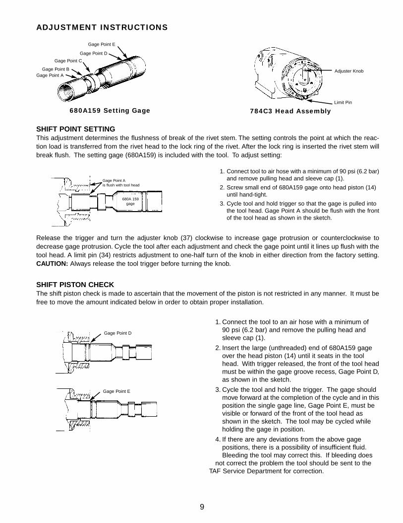
1. Connect the tool to an air hose with a minimum of 90 psi (6.2 bar) and remove the pulling head and sleeve cap (1).
2. Insert the large (unthreaded) end of 680A159 gage over the head piston (14) until it seats in the tool head. With trigger released, the front of the tool headmust be within the gage groove recess, Gage Point D,as shown in the sketch.
3. Cycle the tool and hold the trigger. The gage should move forward at the completion of the cycle and in thisposition the single gage line, Gage Point E, must be visible or forward of the front of the tool head as shown in the sketch. The tool may be cycled while holding the gage in position.
4. If there are any deviations from the above gage positions, there is a possibility of insufficient fluid.Bleeding the tool may correct this. If bleeding does
not correct the problem the tool should be sent to the TAF Service Department for correction.
Gage Point D
Gage Point E
SHIFT POINT SETTINGThis adjustment determines the flushness of break of the rivet stem. The setting controls the point at which the reac-tion load is transferred from the rivet head to the lock ring of the rivet. After the lock ring is inserted the rivet stem willbreak flush. The setting gage (680A159) is included with the tool. To adjust setting:
1. Connect tool to air hose with a minimum of 90 psi (6.2 bar)and remove pulling head and sleeve cap (1).
2. Screw small end of 680A159 gage onto head piston (14)until hand-tight.
3. Cycle tool and hold trigger so that the gage is pulled into the tool head. Gage Point A should be flush with the frontof the tool head as shown in the sketch.
ADJUSTMENT INSTRUCTIONS
Gage Point E
Gage Point D
Gage Point C
Gage Point BGage Point A
Adjuster Knob
Limit Pin
Gage Point Ais flush with tool head
680A 159gage
SHIFT PISTON CHECKThe shift piston check is made to ascertain that the movement of the piston is not restricted in any manner. It must befree to move the amount indicated below in order to obtain proper installation.
Release the trigger and turn the adjuster knob (37) clockwise to increase gage protrusion or counterclockwise todecrease gage protrusion. Cycle the tool after each adjustment and check the gage point until it lines up flush with thetool head. A limit pin (34) restricts adjustment to one-half turn of the knob in either direction from the factory setting.CAUTION: Always release the tool trigger before turning the knob.
680A159 Setting Gage 784C3 Head Assembly
10
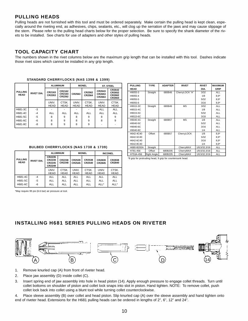
1. Remove knurled cap (A) from front of riveter head.
2. Place jaw assembly (D) inside collet (C).
3. Insert spring end of jaw assembly into hole in head piston (14). Apply enough pressure to engage collet threads. Turn until collet bottoms on shoulder of piston and collet lock snaps into slot in piston. Hand tighten. NOTE: To remove collet, push collet lock back into collet using a blunt tool while turning collet counterclockwise.
4. Place sleeve assembly (B) over collet and head piston. Slip knurled cap (A) over the sleeve assembly and hand tighten onto end of riveter head. Extensions for the H681 pulling heads can be ordered in lengths of 2", 6", 12" and 24".
INSTALLING H681 SERIES PULLING HEADS ON RIVETER
A B C D 14
STANDARD CHERRYLOCKS (NAS 1398 & 1399)
PULLING TYPE ADAPTER RIVET RIVET MAXIMUMHEAD DIA. GRIPH9055-3 Straight 680B46 CherryLOCK “A” 3/32 ALLH9055-4 1/8 8,9*H9055-5 5/32 8,9*H9055-6 3/16 8,9*H9015-3C Straight 680B46 MS 3/32 ALLH9015-4C 1/8 ALLH9015-5C 5/32 ALLH9015-6C 3/16 ALLH9040-4C Straight 680B57 MS 1/8 ALLH9040-5C 5/32 ALLH9040-6C 3/16 ALLH9040-8C 1/4 ALLH642-4C40 Offset 680B57 CherryLOCK 1/8 8,9*H642-5C40 5/32 8,9*H642-6C40 3/16 8,9*H642-8C40 1/4 8,9*H680-B200A Straight CherryMAX 1/8,5/32,3/16 ALLH781-456 Offset 680B205 CherryMAX 1/8,5/32,3/16 ALLH753A-456 Right Angle 680B205 CherryMAX 1/8,5/32,3/16 ALL
*8 grip for protruding head, 9 grip for countersunk head.
TOOL CAPACITY CHARTThe numbers shown in the rivet columns below are the maximum grip length that can be installed with this tool. Dashes indicatethose rivet sizes which cannot be installed in any grip length.
UNIV. CTSK. UNIV. CTSK. UNIV. CTSK.HEAD HEAD HEAD HEAD HEAD HEAD
H681-3C -3 - - - - ALL ALLH681-4C -4 ALL ALL ALL ALL ALL ALLH681-5C -5 8 9 8 9 8 9H681-6C -6 8 9 8 9 8 9H681-8C -8 8 9 8 9 - -
PULLINGHEAD
RIVET DIA. CR2163CR2263
CR2162CR2164CR2262
CR2562CR2564
CR2643CR2653CR2663
CR2642CR2652CR2662CR2664
ALUMINUM ST. STEELMONEL
CR2563
*May require 95 psi (6.6 bar) air pressure at tool.
BULBED CHERRYLOCKS (NAS 1738 & 1739)
UNIV. CTSK. UNIV. CTSK. UNIV. CTSK.HEAD HEAD HEAD HEAD HEAD HEAD
H681-4C -4 ALL ALL ALL ALL ALL ALLH681-5C -5 ALL ALL ALL ALL ALL ALLH681-6C -6 ALL ALL ALL ALL ALL* ALL*
PULLINGHEAD
RIVET DIA.
CR2235CR2239CR2245CR2249
CR2238CR2248
CR2538CR2540
CR2839CR2845
CR2838CR2840
ALUMINUM INCONELMONEL
CR2539CR2545
PULLING HEADSPulling heads are not furnished with this tool and must be ordered separately. Make certain the pulling head is kept clean, espe-cially around the riveting end, as adhesives, chips, sealants, etc., will clog up the serration of the jaws and may cause slippage ofthe stem. Please refer to the pulling head charts below for the proper selection. Be sure to specify the shank diameter of the riv-ets to be installed. See charts for use of adapters and other styles of pulling heads.
11
CROSS SECTION DRAWING OF G784
12
PART LIST FOR THE G784 (195A137) HYDRO-SHIFT RIVETER
46 740R3 HANDLE 1
47 P-838** O-RING, DISOGRIN (.568, .362, .103) 2
48 P-115 RING, BACK-UP (.551, .375, .088) 2
49 P-889 O-RING (1.505, 1.299, .103) 1
50 740B13 PLUG, PACKING 1
51 P-909 RING, BACK-UP (4.245, 3.875, .185) 2
52 P-887 RING, QUAD (4.270, 3.850, .210) 1
53 740B6 PISTON, AIR 1
54 P-737 NUT, CONELOK, 1/4-20 1
55 P-890 O-RING (4.193, 3.987, .103) 1
56 740C4 BASE, HANDLE 1
57 P-886 RING, RETAINING (INT. Ø 4.250) 1
58 740B5 COVER, BASE 1
59 P-884 RING, RETAINING (EXT. Ø 3.375) 1
60 P-885 RING, RETAINING (INT. Ø .781) 1
61 740C7 CYLINDER, POWER 1
62 P-833** O-RING, DISOGRIN (1.068, .862, .103) 1
63 P-892** O-RING, DISOGRIN (1.255, 1.049, .103) 1
64 P-908 RING, BACK-UP (.738, .562, .088) 1
65 P-508 O-RING, (.755, .549, .103) 1
84 740A8 SUB-ASSEMBLY, POWER PISTON & ROD
66 740A11* CAP, PISTON ROD 1
67 740A9* PISTON, POWER 1
68 740A12* STOP, PISTON 1
69 740A10* ROD, POWER PISTON 1
70 740B14 SLEEVE, VALVE 1
71 740A18 SPRING 1
72 P-891** O-RING, DISOGRIN (.566, .426, .070) 3
85 740A15 SUB-ASSEMBLY, VALVE SPOOL 1
73 740B15-1* SPOOL VALVE 1
74 700A18* FILTER 1
75 700A69* SCREW METERING 1
76 P-848 O-RING (.941, .801, .070) 2
77 740B16 PLUG, VALVE 1
78 740A17 MUFFLER 1
79 P-321 RING, RETAINING (INT. Ø 1.000) 1
80 530A34 SWIVEL 1
81 P-195 O-RING (.630, .424, .103) 2
82 530A35 BOLT, SWIVEL 1
86 P-268 O-RING, (.816, .676, .070) 4
41 P-832** O-RING DISOGRIN (.379, .239,.070) 1
42 700A22 GASKET 1
45 P-71 SCREW, SOC. HD. CAP. 10-32X1/2 4
784C3 SUB-ASSEMBLY, HEAD
1 680A103 CAP, SLEEVE 1
2 680A105 SPRING 1
3 680B98 CAP, FRONT 1
4 P-652 RING, BACK-UP (.874, .768, .053) 2
5 P-826 O-RING (.879, .739, .070) 2
6 P-691 O-RING (1.254, 1.114, .070) 2
7 680A21 STOP, PISTON 4
8 680B99 CAP, PISTON 1
9 P-266 O-RING (1.191, 1.051, .070) 1
10 P-651 RING, BACK-UP (.686, .580,.053) 1
11 P-828** O-RING, DISOGRIN (.694, .551, .070) 1
12 P-904** O-RING, DISOGRIN (1.441, 1.301, .070) 2
13 784C2 BODY, HEAD 1
14 680B151 PISTON, HEAD 1
15 P-483 O-RING (1.137, .859, .139) 1
16 P-657 RING, BACK-UP (1.127, .891, .118) 1
17 680A11 SPRING, VALVE 1
83 680A40 SUB-ASSEMBLY, VALVE 1
18 680A20* STEM, VALVE 1
19 P-706 O-RING (.192, .116, 038) 1
20 P-298 O-RING (.566,.426, .070) 1
21 680A18* SEAT, VALVE 1
22 680A19* STOP, SHIFT 1
23 680A10 SPRING, PISTON 1
24 680C3 PISTON, SHIFT 1
25 P-768 RING, RETAINING (INT. Ø.625) 1
26 680A95 SCREW, SHIFT 1
27 P-830** O-RING, DISOGRIN (.629, .489, .070) 1
28 680A308 SUB-ASSEMBLY, RELEASE PISTON 1
29 P-690 O-RING (1.129, .989, .070) 1
30 680B93 CAP, REAR 1
31 P-112 O-RING (.504, .364, .070) 1
32 P-650 RING BACK-UP (.496, .390, .053) 1
33 680A92 WASHER, INDEX 1
34 P-356 SCREW, SOC. HD. CAP, 4-40X1/4 2
35 P-554 SCREW, BUTTON HD. CAP, 1/4-28X3/8 1
36 680A112 RING, ADJUSTER (INCLUDES 680A112-2) 1
37 680A113 KNOB, ADJUSTER 1
38 680A112-2 SPRING, FRICTION 1
39 P-572 STAT-O-SEAL (.430, .180, .125) 2
40 P-573 SCREW, BUTTON HD. CAP 10-32X1/4 2
784C5 ASSEMBLY, HANDLE
43 703A33 ASSEMBLY, TRIGGER (INCLUDES P-223) 1
44 P-223 O-RING (.285, .145, .070) 1
ITEM NO. DESCRIPTION QTY.
*These parts cannot be purchased separately, but must be ordered as a sub-assembly.
** No Substitutions.
All dimensions are in inches.
ITEM NO. DESCRIPTION QTY.
13
EXPLODED VIEW OF G784
Aerospace Fasteners
1224 East Warner Ave., Box 2157
Santa Ana, CA 92707-0157
(714) 545-5511 FAX (714) 850-6095
© 1997 Textron Aerospace Fasteners Supplier’s Federal Identification Code - 11815
Textron Aerospace Fasteners, a Division of Textron Inc. (hereinafter “TAF”), here-by warrants to the initial retail customer (‘Warrantee”) only that its products will befree from defects in material and workmanship, provided that the products areused in accordance with TAF’s instruction as to maintenance, operation and use.The duration of the foregoing warranty is limited to 90 days from the date of firstuse by the Warrantee.
The warrantee’s only remedy and TAF’s only obligation in the event of a defect orfailure in the products, is that TAF will, at its sole option, repair, replace or reworkthe products, but in no case shall the cost of the foregoing exceed the invoice priceof the products.
This Warranty shall be void if any person seeking to make a claim for defective orfailed products fails to notify TAF within thirty (30) days of receipt of evidence thatthe product is defective or has failed, or if said person fails to provide TAF with such
evidence as is reasonably requested concerning the defect or failure, includingwithout limitation, evidence of the date of purchase and date of installation.
THIS WARRANTY IS IN LIEU OF ALL OTHER WARRANTIES, EXPRESSED ORIMPLIED, INCLUDING MERCHANTABILITY OR FITNESS FOR A PARTICULARPURPOSE. TAF EXPRESSLY DISCLAIMS LIABILITY FOR ALL INCIDENTAL,CONSEQUENTIAL, OR SPECIAL DAMAGES ARISING FROM ANY DEFECT ORFAILURE IN ITS PRODUCTS. TAF FURTHER DISCLAIMS ALL LIABILITYRESULTING IN USER’S CHOICE OF ITS PRODUCTS FOR ANY APPLICATION.
The properties, strengths, dimensions, installed characteristics and all other infor-mation in this catalog is for guidance only to aid in the correct selection of the prod-ucts described herein and is not intended or implied as part of the above warran-ty. All applications should be evaluated for functional suitability.
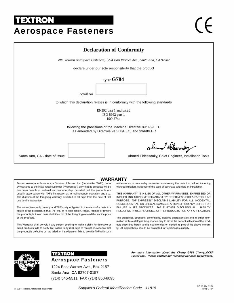
Declaration of Conformity
We, Textron Aerospace Fasteners, 1224 East Warner Ave., Santa Ana, CA 92707
declare under our sole responsibility that the product
type G784
Serial No.--- --- ----------------------------
to which this declaration relates is in conformity with the following standards
EN292 part 1 and part 2ISO 8662 part 1
ISO 3744
following the provisions of the Machine Directive 89/392/EEC(as amended by Directive 91/368/EEC) and 93/68/EEC
Santa Ana, CA - date of issue ____________________ Ahmed Eldessouky, Chief Engineer, Installation Tools
WARRANTY
Aerospace Fasteners
CA-61-3M-1197TMAN-G784
For more information about the Cherry G784 CherryLOCK ®
Power Tool: Please contact our Technical Services Department.