Embed Size (px)
Citation preview
CHERRYloCk® PRoCEss Manual
-4, -5 NAS1097
-6, -8 NAS1097
Head
Head
A-286 CRES C
A-286 CRES
Monel
M
Monel
no identification for aluminum
Head Marking 1
manufacturer’s
identification
gripidentification
material code
(see chart below)
K max.
L max.B
R.010m
ax.
D dia.
A diatheor.
100°±1°
NOT TO
EXCEED“D” DIA.
NOT TOEXCEED
“D” DIA.
Z
grip
BK
BKM
in. blind clearance
for satisfactory
installation.
Rivet head may be
above sheet before
installation.
Head diameters are to theoretical sharp corners
as measured by projection.
100°±1½° for M
onel and A-286
1 NOTE: No mfg. or grip identification on
-4 and -5 diameter fasteners
Sheet thickness for machine countersunk hole
shall not be less than ‘B’ +.010"
.006.002.005.015alum
.Monel

ContEnts
CherryLOCK® Rivet Description .................................... 2How They Work ............................................................. 3Selecting the Correct CherryLOCK® Rivet ..................... 5CherryLOCK® Tools Hydro-shift System ................................................... 8 Limited Access System ........................................... 11 Gages ..................................................................... 12 Maintenance Items ................................................. 13Tool Selection Chart .................................................... 14Hole Preparation ......................................................... 15CherryLOCK® Installation ........................................... 18CherryLOCK® Removal ............................................... 22CherryLOCK® Inspection ............................................ 23Troubleshooting .......................................................... 25Proper Sealant Application ......................................... 27Conversion Table, NAS to CherryLOCK® Numbers ...... 28Decimal Equivalent Chart ............................................ 30Warranty ..................................................................... 31
attEntIon: Blind fasteners are not always interchangeable with non-blind fasteners. Consult with the aircraft Original Equipment Manufacturer for proper application of this product.
2
CHERRYloCk® RIvEts
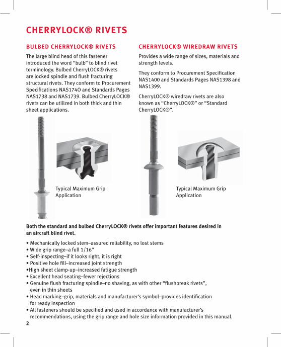
Typical Maximum Grip Application
Typical Maximum Grip Application
BulBED CHERRYloCk® RIvEts
The large blind head of this fastener introduced the word “bulb” to blind rivet terminology. Bulbed CherryLOCK® rivets are locked spindle and flush fracturing structural rivets. They conform to Procurement Specifications NAS174O and Standards Pages NAS1738 and NAS1739. Bulbed CherryLOCK® rivets can be utilized in both thick and thin sheet applications.
CHERRYloCk® WIREDRaW RIvEts
Provides a wide range of sizes, materials and strength levels.
They conform to Procurement Specification NAS1400 and Standards Pages NAS1398 and NAS1399.
CherryLOCK® wiredraw rivets are also known as “CherryLOCK®” or “Standard CherryLOCK®”.
Both the standard and bulbed CherryloCk® rivets offer important features desired in an aircraft blind rivet.
• Mechanically locked stem–assured reliability, no lost stems• Wide grip range–a full 1/16"• Self-inspecting–if it looks right, it is right• Positive hole fill–increased joint strength•High sheet clamp-up–increased fatigue strength• Excellent head seating–fewer rejections• Genuine flush fracturing spindle–no shaving, as with other “flushbreak rivets”,
even in thin sheets• Head marking–grip, materials and manufacturer’s symbol–provides identification
for ready inspection• All fasteners should be specified and used in accordance with manufacturer’s
recommendations, using the grip range and hole size information provided in this manual.

3
HoW tHEY WoRk
BulBED CHERRYloCk® RIvEts
1. Before pulling begins.
2. Stem is pulled into rivet sleeve and starts to form bulbed blind head.
Clamp-up and hole fill action
begin.
3. Clamp-up completed as stem continues to bulb out blind head.
4. Formation of blind head and hole filling are completed.
Shear ring now begins to shear from stem cone
to allow stem to pull further into rivet.
5. Shear ring has moved down stem cone until pulling head automati-cally stops stem break notch flush with top of rivet head.
Locking collar is now ready to be inserted.
6. Completely installed bulbed CherryLOCK® rivet
Pulling head has inserted locking collar and stem has fractured flush with rivet head.
(maximum grip illustrated)
lockingcollar
stem
rivethead
rivetsleeve shear
ring
sheetgap
rivet headfirmly seated
Note: In minimum grip, shear ring may not shear
ShearRing
4
HoW tHEY WoRk
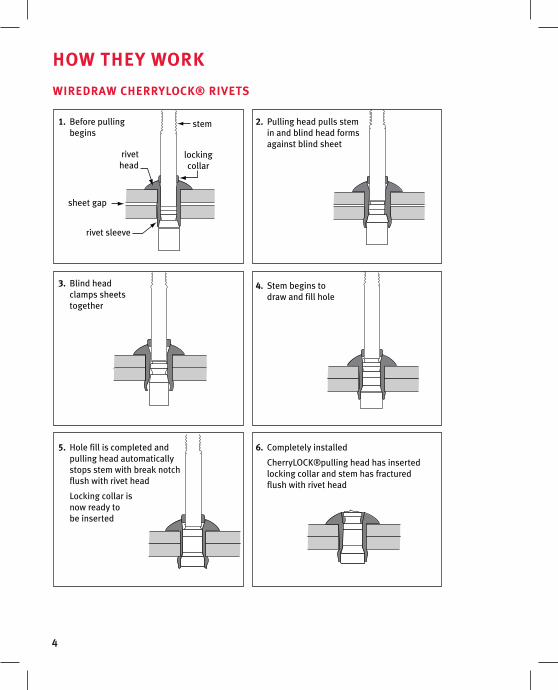
WIREDRaW CHERRYloCk® RIvEts
stem
rivethead
lockingcollar
sheet gap
rivet sleeve
6. Completely installed
CherryLOCK®pulling head has inserted locking collar and stem has fractured flush with rivet head
5. Hole fill is completed and pulling head automatically stops stem with break notch flush with rivet head
Locking collar is now ready to be inserted
4. Stem begins to draw and fill hole
3. Blind head clamps sheets together
1. Before pulling begins
2. Pulling head pulls stem in and blind head forms against blind sheet
5
sElECtInG tHE RIvEt
CHERRYloCk® anD BulBED CHERRYloCk®
Wiredraw CherryLOCK® and bulbed CherryLOCK® rivets should be used as a complete fastening system so that the best features of each can be utilized for optimum strength and performance.
Bulbed CherryLOCK® is a complete shear fastening system. Its features can be utilized for optimum strength and performance in both thick and thin sheet. It provides the highest possible design integrity, particularly in double dimple or high vibration areas.
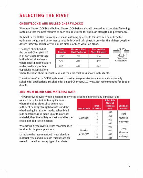
The large blind head of the bulbed CherryLOCK® is of particular advantage in thin blind side sheets where sheet bearing failure under load is a problem, especially in applications where the blind sheet is equal to or less than the thickness shown in this table:
The wiredraw CherryLOCK® system with its wider range of sizes and materials is especially suitable for applications unsuitable for bulbed CherryLOCK® rivets. Not recommended for double dimple.
MInIMuM BlInD sIDE MatERIal Data
The wiredrawing type rivet is designed to give the best hole filling of any blind rivet and as such must be limited to applications where the blind side substructure has sufficient bearing strength to withstand the wiredrawing installation loads. When blind side substructure is made up of thin or soft material, then the bulb type rivet would be the recommended rivet selection.
Wiredrawing type rivets are not recommended for double dimple applications.
Listed are the recommended rivet selection material types and minimum thicknesses for use with the wiredrawing type blind rivets.
Blind Sheet(Substructure)
Rivet MaterialRivet
Diameter
Blind side Material
thickness (min)
Blind side Material
Aluminum
-4-5-6-8
.030
.040
.050
.060
2024
Aluminum
or stronger
Monel &
A-286 CRES
-4-5-6-8
.040
.050
.060
.080
7075
Aluminum
or stronger
Rivet Diameter
aluminum Blind sheet thickness
titanium Blind sheet thickness
1/8" .040 .020
5/32" .040 .032
3/16" .050 .032
6
sElECtInG tHE RIvEt
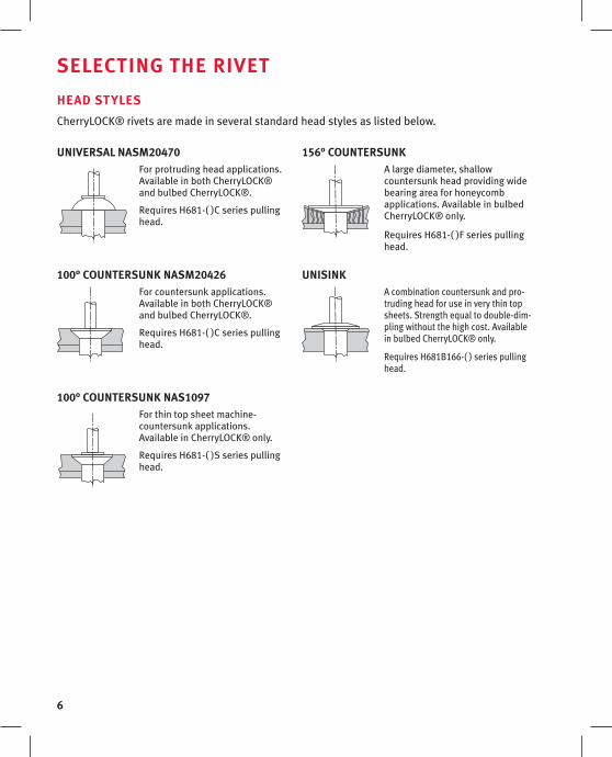
HEaD stYlEs
CherryLOCK® rivets are made in several standard head styles as listed below.
unIvERsal nasM20470For protruding head applications.Available in both CherryLOCK® and bulbed CherryLOCK®.
Requires H681-( )C series pulling head.
100° CountERsunk nasM20426For countersunk applications. Available in both CherryLOCK® and bulbed CherryLOCK®.
Requires H681-( )C series pulling head.
100° CountERsunk nas1097For thin top sheet machine- countersunk applications. Available in CherryLOCK® only.
Requires H681-( )S series pulling head.
156° CountERsunkA large diameter, shallow countersunk head providing wide bearing area for honeycomb applications. Available in bulbed CherryLOCK® only.
Requires H681-( )F series pulling head.
unIsInkA combination countersunk and pro-truding head for use in very thin top sheets. Strength equal to double-dim-pling without the high cost. Available in bulbed CherryLOCK® only.
Requires H681B166-( ) series pulling head.
7
sElECtInG tHE RIvEt
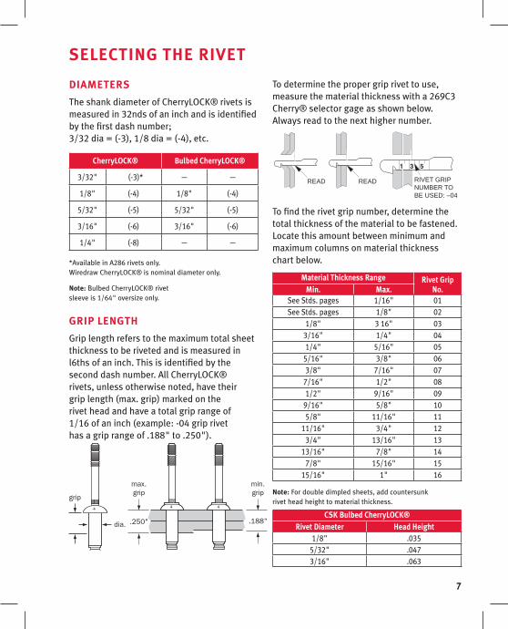
DIaMEtERs
The shank diameter of CherryLOCK® rivets is measured in 32nds of an inch and is identified by the first dash number; 3/32 dia = (-3), 1/8 dia = (-4), etc.
CherryloCk® Bulbed CherryloCk®
3/32" (-3)* — —
1/8" (-4) 1/8" (-4)
5/32" (-5) 5/32" (-5)
3/16" (-6) 3/16" (-6)
1/4" (-8) — —
*Available in A286 rivets only. Wiredraw CherryLOCK® is nominal diameter only.
note: Bulbed CherryLOCK® rivet sleeve is 1/64" oversize only.
GRIP lEnGtH
Grip length refers to the maximum total sheet thickness to be riveted and is measured in l6ths of an inch. This is identified by the second dash number. All CherryLOCK® rivets, unless otherwise noted, have their grip length (max. grip) marked on the rivet head and have a total grip range of 1/16 of an inch (example: -04 grip rivet has a grip range of .188" to .250").
To determine the proper grip rivet to use, measure the material thickness with a 269C3 Cherry® selector gage as shown below. Always read to the next higher number.
To find the rivet grip number, determine the total thickness of the material to be fastened. Locate this amount between minimum and maximum columns on material thickness chart below.
Material thickness Range Rivet Grip no.Min. Max.
See Stds. pages 1/16" 01See Stds. pages 1/8" 02
1/8" 3 16" 033/16" 1/4" 041/4" 5/16" 05
5/16" 3/8" 063/8" 7/16" 07
7/16" 1/2" 081/2" 9/16" 09
9/16" 5/8" 105/8" 11/16" 11
11/16" 3/4" 123/4" 13/16" 13
13/16" 7/8" 147/8" 15/16" 15
15/16" 1" 16
note: For double dimpled sheets, add countersunk rivet head height to material thickness.
Csk Bulbed CherryloCk®Rivet Diameter Head Height
1/8" .0355/32" .0473/16" .063
READ READ RIVET GRIPNUMBER TOBE USED: –04

8
G700* G784* G689** G686B-s**
The CherryLOCK® hydro-shift tooling system is an advanced design in which the sequence of operations necessary to install the rivet is accomplished hydraulically within the hydro-shift tool rather than by means of a mechanical pulling head.
See the tool selection chart on page 14 of this manual for the capacity of each of these hydro-shift tools.
* Capable of installing rivet group A only ** Capable of installing rivet group A, B and C
H681 PullInG HEaDs
Attach directly to hydro-shift tools G700, G784, G689 and G686B-s.
CHERRYloCk® tools
CHERRYloCk® HYDRo-sHIft sYstEM

9
CHERRYloCk® tools
sElECtIon of PRoPER HYDRo-sHIft PullInG HEaD
H681 sERIEs
A separate pulling head is required for each diameter CherryLOCK® rivet. It is acceptable that countersunk (C) pulling heads be used for installing both universal and countersunk head CherryLOCK® rivets. These heads fit directly on all Cherry® hydro-shift riveters.
2-9/16"
A
B
.600" 25/32"
Rivet Dia. Pulling Head numberDim.
a B
3/32" H681-3C Universal Head Countersunk Head (NASM20426)
.163 .332
1/8" H681-4C Universal Head Countersunk Head (NASM20426)
.208 .341
H681-4F Countersunk Head (156°) .430 .358
H681 -4S Countersunk Head (NAS1097) .174 .341
H681B166-4 Unisink Head .250 .359
5/32" H681-5C Universal Head Countersunk Head (NASM20426)
.269 .352
H681-5F Countersunk Head (156°) .535 .338
H681-5S Countersunk Head (NAS1097) .225 .352
H681B166-5 Unisink Head .313 .377
3/16" H681-6C Universal Head Countersunk Head (NASM20426)
.335 .386
H681-6F Countersunk Head (156°) .625 .367
H681-6S Countersunk Head (NAS1097) .281 .386
H681B166-6 Unisink Head .375 .419
1/4" H681-8C Universal Head Countersunk Head (NASM20426)
.458 .398
H681-8S Countersunk Head (NAS1097) .274 .398

10
CHERRYloCk® tools
sElECtIon of PRoPER HYDRo-sHIft PullInG HEaD
InstallInG H681 PullInG HEaD on RIvEtER
Remove knurled cap a from front of riveter head.
Place jaw assembly D inside collet C.
Insert spring end of jaw assembly into hole in head piston E. Apply enough pressure to engage collet threads. Turn until collet bottoms on shoulder of piston and collet lock snaps into slot in piston. Hand tightening is sufficient. note: To remove collet, push collet lock back into collet (using a blunt pointed tool) while turning the collet counterclockwise.
Place sleeve assembly B over collet and head piston. Slip knurled cap a over the sleeve assembly and hand tighten onto end of riveter head.
notE: Hydro-shift riveters are factory adjusted to break rivet stem flush and set collar properly. Fine adjustments to the shift point setting can be made by the operator. This adjustment determines the flushness of break of the rivet stem and may be accomplished as follows:
Make sure the riveter is connected to air supply.
With trigger released, turn adjuster knob clockwise to lower stem break and counter-clockwise to raise stem break. Always release tool trigger before turning knob.
A limit pin restricts adjustment to one-half turn of knob either direction from factory setting. Do not remove this limit pin. If more than one-half turn adjustment is required to achieve flush stem break, tool should be returned to your Tool Maintenance Department for checking with 680A159 gage. See page 12.
11
CHERRYloCk® tools
lIMItED aCCEss aPPlICatIons
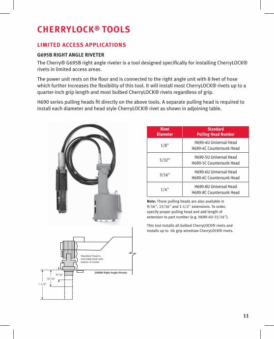
G695B RIGHt anGlE RIvEtER
The Cherry® G695B right angle riveter is a tool designed specifically for installing CherryLOCK® rivets in limited access areas.
The power unit rests on the floor and is connected to the right angle unit with 8 feet of hose which further increases the flexibility of this tool. It will install most CherryLOCK® rivets up to a quarter-inch grip length and most bulbed CherryLOCK® rivets regardless of grip.
H690 series pulling heads fit directly on the above tools. A separate pulling head is required to install each diameter and head style CherryLOCK® rivet as shown in adjoining table.
Rivet Diameter
standard Pulling Head number
1/8"H690-4U Universal Head
H690-4C Countersunk Head
5/32"H690-5U Universal Head
H690-5C Countersunk Head
3/16"H690-6U Universal Head
H690-6C Countersunk Head
1/4"H690-8U Universal Head
H690-8C Countersunk Head
note: These pulling heads are also available in 9/16", 15/16" and 1-1/2" extensions. To order, specify proper pulling head and add length of extension to part number (e.g. H690-4U-15/16").
This tool installs all bulbed CherryLOCK® rivets and installs up to -04 grip wiredraw CherryLOCK® rivets.
1-1/2"
15/16"9/16"
Standard Head isnominally flush withbottom of riveter
G695B Right Angle Riveter

12
CHERRYloCk® tools
GaGEs
269C3 GRIP GaGE
A simple, self-explanatory gage for determining material thickness and proper rivet grip length.
t172 RIvEt HolE sIZE GaGE
These are precision ground, go no-go gages used to check holes drilled for Cherry® blind rivets. They are made in all standard rivet diameters plus the oversize rivet diameters.
628 sEttInG GaGEs
These gages are used to adjust the shift point and lock ring anvil settings on CherryLOCK® mechanical pulling heads H615B, H640B, H642 and H690. A separate gage is required for each rivet diameter and the correct gage is furnished with each new pulling head along with instructions for its use.
680a159 sEttInG GaGE
This gage is used to adjust the shift point setting on Cherry® hydro-shift riveters. One of these gages is furnished with each new hydro-shift riveter, along with instructions for its use.
anvIl GaGEs
These go no-go gages are used to check the hole diameters of lock ring anvils in all CherryLOCK® pulling heads H681 and H690. Their use will help eliminate installation problems caused by worn, oversized anvils. A separate gage is required for each rivet diameter.
Rivet Dia. Gage no.
1/8" 628-4 (green)
5/32" 628-5 (red)
3/16" 628-6 (blue)
1/4" 628-8 (aluminum)
Rivet Dia. Gage no.
3/32" P913
1/8" P856
5/32" P857
3/16" P858
1/4" P859
Rivet Diameter
Hole Gage Part numbersstandard Bulbed
3/32" T172-3 —
1/8" T172-4 T172-400
5/32" T172-5 T172-500
3/16" T172-6 T172-600
1/4" T172-8 —

13
CHERRYloCk® tools
MaIntEnanCE ItEMs
700a77 aIR BlEEDER
To keep Cherry® rivet hydraulic tools operating at peak efficiency, it is absolutely essential that the hydraulic systems be kept full of fluid and free of air.
Based on the same principle used in bleeding the hydraulic brake system of an automobile, the 700A77 Cherry® air bleeder will quickly and easily remove all air and assure the complete filling of the tool with Dexron III automatic transmission fluid. It may be used in the tool crib or right on the production line, since it requires but a few minutes to perform this vital function. The air bleeder is a small item, but it does a really big job: it prevents downtime.
sERvICE kIts
An assortment of O-rings, seals, screws, washers and gaskets is available in kit form for each Cherry® power tool. To avoid unnecessary downtime, it is advisable to have these kits on hand for the tools being serviced.
Cherry® tool service kit no.
G685B-S & G686B-S G685-S/686-SKS
G689 G689KS
G695B G695KS
G700 G700KS
G715A G715KS
G740A G740KS
G784 G784KS
14
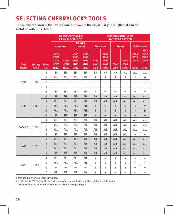
The numbers shown in the rivet columns below are the maximum grip length that can be installed with these tools.
toolModel
PullingHead
RivetDia.
Bulbed CherryloCk® nas1738 & nas1739
standard CherryloCk® nas1398 & nas1399
aluminumMonel & Inconel aluminum Monel CREs Inconel
2235223922452249
22382248
2539254528392845
2538254028382840
21632263
2162216422622264 2563
25622564
264326532663
2
2642265226622664
2
univ. Ctsk. univ. Ctsk. univ. Ctsk. univ. Ctsk. univ. Ctsk.
G700 H681
-3 NA NA NA NA NA NA NA NA ALL ALL
-4 ALL ALL ALL ALL 8 9 8 9 8 9
-5 — — — — — — — — — —
-6 — — — — — — — — — —
-8 NA NA NA NA — — — — — —
G784 H681
-3 NA NA NA NA NA NA NA NA ALL ALL
-4 ALL ALL ALL ALL ALL ALL ALL ALL ALL ALL
-5 ALL ALL ALL ALL 8 9 8 9 8 9
-6 ALL ALL ALL1 ALL1 8 9 8 9 81 91
-8 NA NA NA NA — — — — — —
G686B-S H681
-4 ALL ALL ALL ALL ALL ALL ALL ALL ALL ALL
-5 ALL ALL ALL ALL ALL ALL ALL ALL ALL ALL
-6 ALL ALL ALL ALL ALL ALL ALL ALL ALL ALL
-8 NA NA NA NA ALL ALL ALL ALL — —
G689 H681
-4 ALL ALL ALL ALL ALL ALL ALL ALL ALL ALL
-5 ALL ALL ALL ALL ALL ALL ALL ALL ALL ALL
-6 ALL ALL ALL ALL ALL ALL ALL ALL ALL ALL
-8 NA NA NA NA ALL ALL ALL ALL ALL ALL
G695B H690
-4 ALL ALL ALL ALL 4 4 4 4 4 4
-5 ALL ALL ALL ALL 4 4 4 4 4 4
-6 — — — — 4 4 4 4 — —
-8 NA NA NA NA 4 4 — — — —
1 May require 95 PSI air pressure at tool 2 3/32" A-286 (CR2662 & CR2663) rivets may be installed with any Cherry® hydro-shift riveter — indicates rivet sizes which cannot be installed in any grip length
sElECtInG CHERRYloCk® tools
15
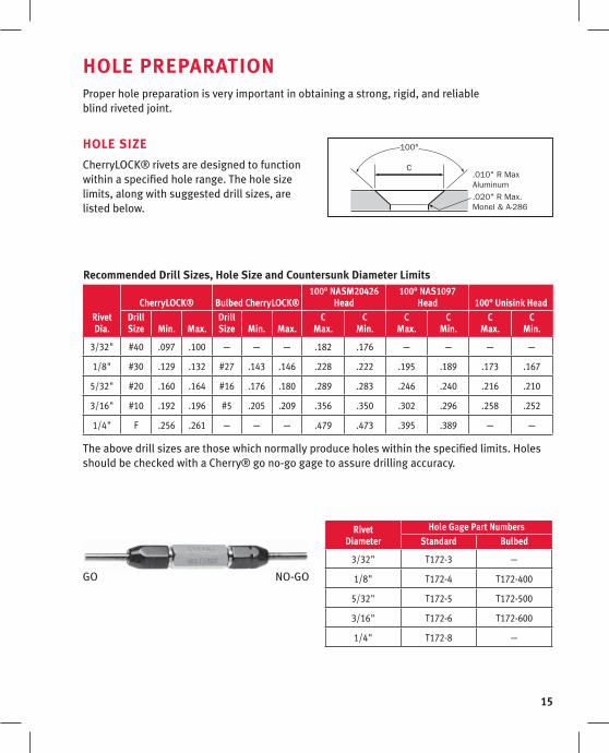
HolE PREPaRatIonProper hole preparation is very important in obtaining a strong, rigid, and reliable blind riveted joint.
HolE sIZE
CherryLOCK® rivets are designed to function within a specified hole range. The hole size limits, along with suggested drill sizes, are listed below.
Recommended Drill sizes, Hole size and Countersunk Diameter limits
RivetDia.
CherryloCk® Bulbed CherryloCk®100° nasM20426
Head100° nas1097
Head 100° unisink HeadDrillsize Min. Max.
Drillsize Min. Max.
CMax.
CMin.
CMax.
CMin.
CMax.
CMin.
3/32" #40 .097 .100 — — — .182 .176 — — — —
1/8" #30 .129 .132 #27 .143 .146 .228 .222 .195 .189 .173 .167
5/32" #20 .160 .164 #16 .176 .180 .289 .283 .246 .240 .216 .210
3/16" #10 .192 .196 #5 .205 .209 .356 .350 .302 .296 .258 .252
1/4" F .256 .261 — — — .479 .473 .395 .389 — —
The above drill sizes are those which normally produce holes within the specified limits. Holes should be checked with a Cherry® go no-go gage to assure drilling accuracy.
Rivet Diameter
Hole Gage Part numbersstandard Bulbed
3/32" T172-3 —
1/8" T172-4 T172-400
5/32" T172-5 T172-500
3/16" T172-6 T172-600
1/4" T172-8 —
GO NO-GO
C
100°
.010" R Max Aluminum.020" R Max. Monel & A-286
16
HolE PREPaRatIon
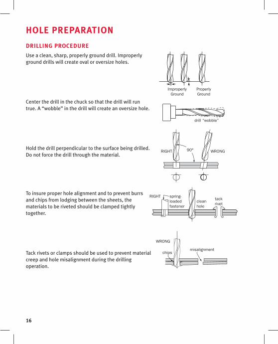
DRIllInG PRoCEDuRE
Use a clean, sharp, properly ground drill. Improperly ground drills will create oval or oversize holes.
Center the drill in the chuck so that the drill will run true. A “wobble” in the drill will create an oversize hole.
Hold the drill perpendicular to the surface being drilled. Do not force the drill through the material.
To insure proper hole alignment and to prevent burrs and chips from lodging between the sheets, the materials to be riveted should be clamped tightly together.
Tack rivets or clamps should be used to prevent material creep and hole misalignment during the drilling operation.
RIGHT WRONG
ProperlyGround
ImproperlyGround
chipsmisalignment
drill “wobble”
RIGHT spring-loadedfastener
cleanhole
90°
WRONG
tackrivet
17
HolE PREPaRatIon
CountERsInkInG
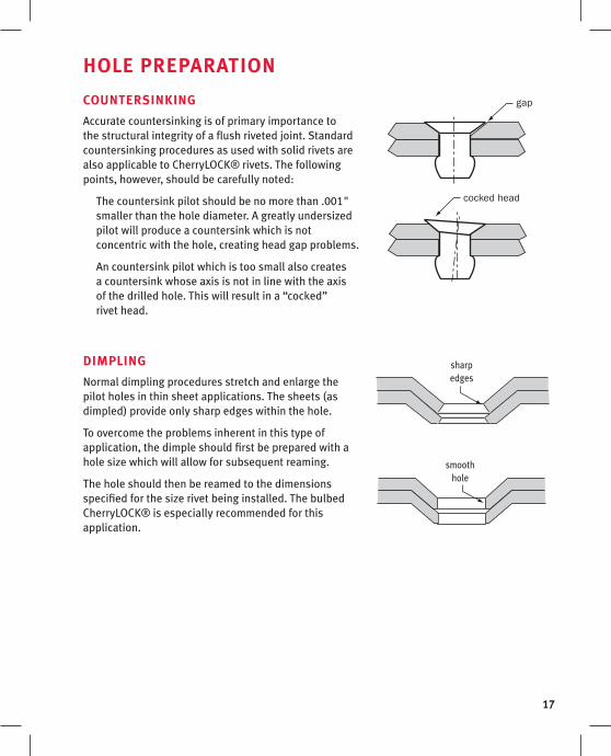
Accurate countersinking is of primary importance to the structural integrity of a flush riveted joint. Standard countersinking procedures as used with solid rivets are also applicable to CherryLOCK® rivets. The following points, however, should be carefully noted:
The countersink pilot should be no more than .001" smaller than the hole diameter. A greatly undersized pilot will produce a countersink which is not concentric with the hole, creating head gap problems.
An countersink pilot which is too small also creates a countersink whose axis is not in line with the axis of the drilled hole. This will result in a “cocked” rivet head.
DIMPlInG
Normal dimpling procedures stretch and enlarge the pilot holes in thin sheet applications. The sheets (as dimpled) provide only sharp edges within the hole.
To overcome the problems inherent in this type of application, the dimple should first be prepared with a hole size which will allow for subsequent reaming.
The hole should then be reamed to the dimensions specified for the size rivet being installed. The bulbed CherryLOCK® is especially recommended for this application.
cocked head
gap
sharp edges
smooth hole
18
burr
burr
remove burrs
remove chips
Poor
Good
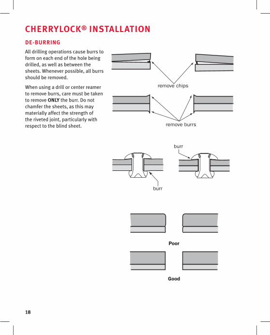
CHERRYloCk® InstallatIon DE-BuRRInG
All drilling operations cause burrs to form on each end of the hole being drilled, as well as between the sheets. Whenever possible, all burrs should be removed.
When using a drill or center reamer to remove burrs, care must be taken to remove onlY the burr. Do not chamfer the sheets, as this may materially affect the strength of the riveted joint, particularly with respect to the blind sheet.
19
CHERRYloCk® InstallatIon
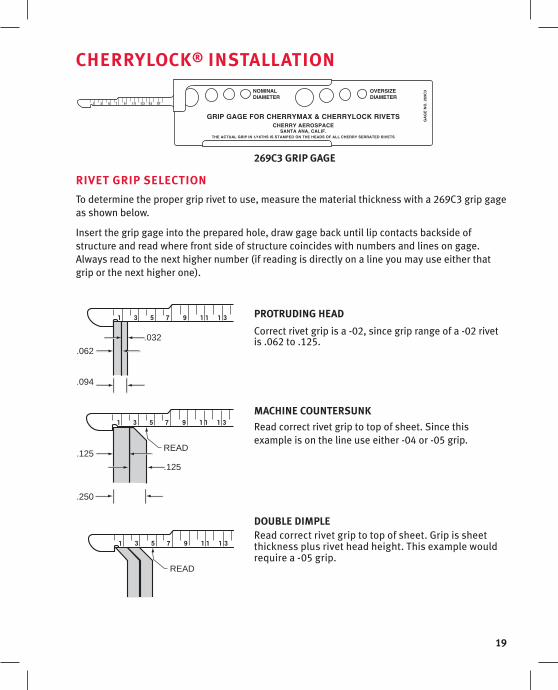
269C3 GRIP GaGE
RIvEt GRIP sElECtIon
To determine the proper grip rivet to use, measure the material thickness with a 269C3 grip gage as shown below.
Insert the grip gage into the prepared hole, draw gage back until lip contacts backside of structure and read where front side of structure coincides with numbers and lines on gage. Always read to the next higher number (if reading is directly on a line you may use either that grip or the next higher one).
PRotRuDInG HEaD
Correct rivet grip is a -02, since grip range of a -02 rivet is .062 to .125.
MaCHInE CountERsunk
Read correct rivet grip to top of sheet. Since this example is on the line use either -04 or -05 grip.
DouBlE DIMPlERead correct rivet grip to top of sheet. Grip is sheet thickness plus rivet head height. This example would require a -05 grip.
.032
.062
.125
.125
.094
.250
READ
READ

20
CHERRYloCk® InstallatIon PlaCInG RIvEt In HolE
Select the proper pulling head to conform to the diameter and head style of CherryLOCK® rivet being installed. The rivet is now ready to be placed in the hole.
The holes in the sheets to be fastened must be of correct size and aligned properly. Do not force the rivet into the hole.
In limited blind clearance applications, the manufactured head of the standard CherryLOCK® rivet can protrude above the top sheet and will pull down to the sheet as the stem is pulled in. The minimum blind clearance is the “BK” dimension; this is listed on our Standards Pages.
PlaCInG PullInG HEaD on RIvEt stEM
Hold the riveter and pulling head in line with the axis of the rivet, while holding the riveter in a light and flexible manner.
notE: CherryLOCK® wiredraw rivets require longer stroke installation tools than the CherryLOCK® bulbed rivet.
Stroke requirements increase with the increase in grip length.
There are three groups (or stroke settings) for CherryLOCK® wiredraw rivets. These are identified in the CherryLOCK® catalog under each wiredraw part number. See “Rivet Group” in the CherryLOCK® wiredraw portion of the catalog for stroke limits.
obstruction
misalignedhole
Right Wrong
Right Wrong
21
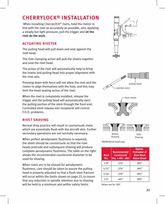
CHERRYloCk® InstallatIon When installing CherryLOCK® rivets, hold the riveter in line with the rivet as accurately as possible, and, applying a steady but light pressure, pull the trigger and let the rivet do the work.
aCtuatInG RIvEtER
The pulling head will pull down and seat against the rivet head.
The rivet clamping action will pull the sheets together and seat the rivet head.
The action of the rivet will automatically help to bring the riveter and pulling head into proper alignment with the rivet axis.
Pressing down with force will not allow the rivet and the riveter to align themselves with the hole, and this may limit the head seating action of the rivet.
When the rivet is completely installed, release the trigger and the pulling head will automatically eject the pulling portion of the stem through the front end. Controlled stem release into receptacle will control F.O.D. problems.
RIvEt sHavInG
Normal shop practice will result in countersunk rivets which are essentially flush with the aircraft skin. Further secondary operations are not normally necessary.
When perfect aerodynamic flushness is required, the sheet should be countersunk so that the rivet heads protrude and subsequent shaving will produce complete aerodynamic flushness. The table on the right shows the recommended countersink diameter to be used for shaving.
When rivets are to be shaved for aerodynamic flushness, care should be taken to assure the pulling head is properly adjusted so that a flush stem fracture will occur within the limits shown on page 23, to insure that any reduction in spindle retention due to shaving will be held to a minimum and within safety limits.
flush break
BeforeShaving
AfterShaving
ejected stem
pulling head
NASM20426 head only.
Rivet Dia.
Recommended Countersink
Dia. +.005 -.000
approx. Protrusion of
Rivet Head above sheet
1/8" .214" .005"
5/32" .274" .005"
3/16" .339" .005"
1/4" .461" .005"
Values are for 100°

22
RIvEt REMoval Should it be necessary to remove an installed CherryLOCK® rivet, the following procedures are recommended:
1. In thick material remove the lock by driving out the rivet stem, using a pin punch.
2. If the rivets have been installed in thin sheets, driving out the locked stem may damage the sheets. It is recommended that the stem be center punched first and a small center drill be used to provide a guide for a larger drill on top of the rivet stem. The larger drill can then be used to drill away the lock. Finally, use a pin punch to drive out the stem.
3. Drill nearly through the head of the rivet, using a drill the same size as the rivet shank. Do not drill completely through rivet head.
4. Break off rivet head, using a pin punch as a pry.
5. Drive out the remaining rivet shank with a pin punch having a diameter equal to the rivet shank.
CautIon: Never drill completely through the rivet sleeve to remove a rivet as this will tend to enlarge the hole.

23
CHERRYloCk® InsPECtIonInspection for the proper installation of CherryLOCK® rivets can be made from the visible side of the work.
stEM anD CollaR flusHnEss
If the rivet stem and collar are flush within the limits described it can be safely concluded that a satisfactory blind head and lock has been formed.
Rivet size
-3Dia.
-4 Dia.
-5 Dia.
-6 Dia.
-8 Dia.
A max. .015 .015 .020 .025 .030
B max. .010 .010 .010 .015 .020
Inspect installed rivet flushness to break-off limits of NAS1400 and NAS1740
A = Collar above breaknotch of stem B = Collar above top of rivet head
A slight collar “flash” caused by the pressures necessary to drive the collar is acceptable within the limit shown.
STEM PROTRUSION LIMITS
COLLAR PROTRUSION LIMITS
COLLAR FLASH
24
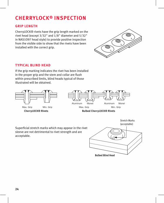
CHERRYloCk® InsPECtIonGRIP lEnGtH
CherryLOCK® rivets have the grip length marked on the rivet head (except 3/32" and 1/8" diameter and 5/32" in NAS1O97 head style) to provide positive inspection from the visible side to show that the rivets have been installed with the correct grip.
tYPICal BlInD HEaD
If the grip marking indicates the rivet has been installed in the proper grip and the stem and collar are flush within prescribed limits, blind heads typical of those illustrated will be obtained.
Superficial stretch marks which may appear in the rivet sleeve are not detrimental to rivet strength and are acceptable.
MonelAluminumMonelAluminum
Max. Grip Min. GripMax. Grip Min. Grip
CherryloCk® Rivets Bulbed CherryloCk® Rivets
Bulbed Blind Head
Stretch Marks (acceptable)
25
tRouBlEsHootInGThe correct installation of CherryLOCK® rivets requires that the instructions contained in this manual regarding hole preparation, tools and installation technique be carefully followed.
It is imperative that the pulling heads be clean, free from chips, burrs and dry sealant and are in proper adjustment and mechanical repair.
The following trouble shooting guide will consider several sources for each problem and a solution for each.
The following problems and solutions apply to both bulbed and CherryLOCK® rivets.
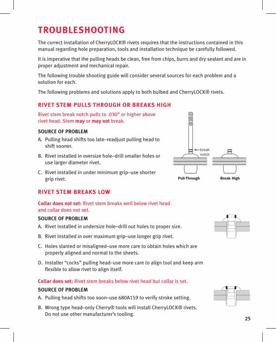
RIvEt stEM Pulls tHRouGH oR BREaks HIGH
Rivet stem break notch pulls to .030” or higher above rivet head. Stem may or may not break.
souRCE of PRoBlEM
Pulling head shifts too late–readjust pulling head to A. shift sooner.
Rivet installed in oversize hole–drill smaller holes or B. use larger diameter rivet.
Rivet installed in under minimum grip–use shorter C. grip rivet.
RIvEt stEM BREaks loW
Collar does not set: Rivet stem breaks well below rivet head and collar does not set.
souRCE of PRoBlEM
Rivet installed in undersize hole–drill out holes to proper size.A.
Rivet installed in over maximum grip–use longer grip rivet.B.
Holes slanted or misaligned–use more care to obtain holes which are C. properly aligned and normal to the sheets.
Installer “cocks” pulling head–use more care to align tool and keep arm D. flexible to allow rivet to align itself.
Collar does set: Rivet stem breaks below rivet head but collar is set.
souRCE of PRoBlEM
Pulling head shifts too soon–use 680A159 to verify stroke setting.A.
Wrong type head–only Cherry® tools will install CherryLOCK® rivets. B. Do not use other manufacturer’s tooling.
breaknotch
Pull-Through Break High
26
tRouBlEsHootInG
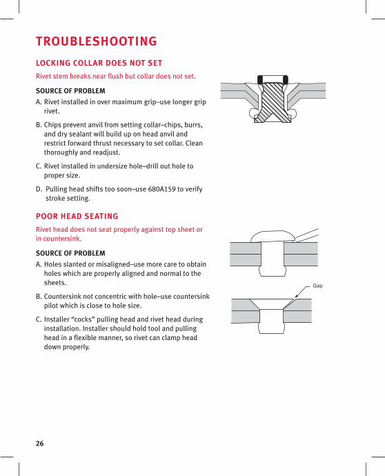
loCkInG CollaR DoEs not sEt
Rivet stem breaks near flush but collar does not set.
souRCE of PRoBlEM
Rivet installed in over maximum grip–use longer grip A. rivet.
Chips prevent anvil from setting collar–chips, burrs, B. and dry sealant will build up on head anvil and restrict forward thrust necessary to set collar. Clean thoroughly and readjust.
Rivet installed in undersize hole–drill out hole to C. proper size.
Pulling head shifts too soon–use 680A159 to verify D. stroke setting.
PooR HEaD sEatInG
Rivet head does not seat properly against top sheet or in countersink.
souRCE of PRoBlEM
Holes slanted or misaligned–use more care to obtain A. holes which are properly aligned and normal to the sheets.
Countersink not concentric with hole–use countersink B. pilot which is close to hole size.
Installer “cocks” pulling head and rivet head during C. installation. Installer should hold tool and pulling head in a flexible manner, so rivet can clamp head down properly.
Gap

27
PRoPER sEalant aPPlICatIonBlind rivets depend on a balance of lubricity to friction, compression and radial expansion during installation. In the manufacturing process, lubricants are typically used to ensure the blind rivet installs correctly.
Sealant should be applied ONLY around the rivet sleeve (see illustration). It is critical that the sealant does not touch either the lock collar or the plug section of the fastener.
Do not apply sealant on these areas
Apply sealant here only!
When sealant is applied to the fastener incorrectly, two conditions may occur. Either the stem of the fastener will pull high or all the way through the rivet sleeve, or the stem will break prematurely and will be too deep in the rivet sleeve to be properly locked by the lock collar. In either case, the rivet must be removed and replaced. Initial care in the application of sealant will eliminate this replacement process.
28
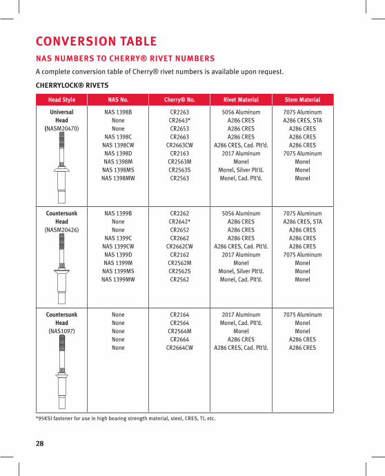
ConvERsIon taBlE nas nuMBERs to CHERRY® RIvEt nuMBERs
A complete conversion table of Cherry® rivet numbers is available upon request.
CHERRYloCk® RIvEts
Head style nas no. Cherry® no. Rivet Material stem Material
universal Head
(NASM20470)
NAS 1398BNoneNone
NAS 1398CNAS 1398CWNAS 1398DNAS 1398M
NAS 1398MSNAS 1398MW
CR2263CR2643*CR2653CR2663
CR2663CWCR2163
CR2563MCR2563SCR2563
5056 AluminumA286 CRES A286 CRESA286 CRES
A286 CRES, Cad. Plt’d.2017 Aluminum
MonelMonel, Silver Plt’d.Monel, Cad. Plt’d.
7075 AluminumA286 CRES, STA
A286 CRESA286 CRESA286 CRES
7075 AluminumMonelMonelMonel
CountersunkHead
(NASM20426)
NAS 1399BNoneNone
NAS 1399CNAS 1399CWNAS 1399DNAS 1399M
NAS 1399MSNAS 1399MW
CR2262CR2642*CR2652CR2662
CR2662CWCR2162
CR2562MCR2562SCR2562
5056 AluminumA286 CRESA286 CRESA286 CRES
A286 CRES, Cad. Plt’d.2017 Aluminum
MonelMonel, Silver Plt’d.Monel, Cad. Plt’d.
7075 AluminumA286 CRES, STA
A286 CRESA286 CRESA286 CRES
7075 Aluminum MonelMonel Monel
CountersunkHead
(NAS1097)
NoneNoneNoneNoneNone
CR2164 CR2564
CR2564M CR2664
CR2664CW
2017 Aluminum Monel, Cad. Plt’d.
MonelA286 CRES
A286 CRES, Cad. Plt’d.
7075 AluminumMonelMonel
A286 CRESA286 CRES
*95KSI fastener for use in high bearing strength material, steel, CRES, TI, etc.
29
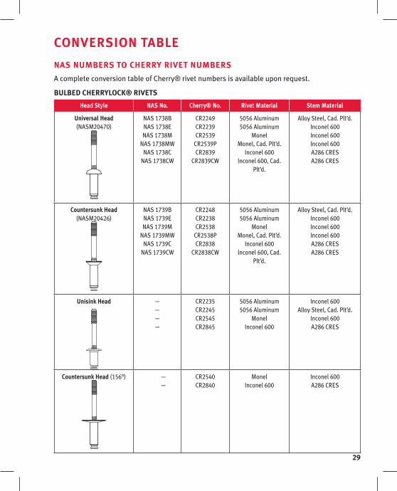
ConvERsIon taBlE
nas nuMBERs to CHERRY RIvEt nuMBERs
A complete conversion table of Cherry® rivet numbers is available upon request.
BulBED CHERRYloCk® RIvEts
Head style nas no. Cherry® no. Rivet Material stem Material
universal Head(NASM20470)
NAS 1738B NAS 1738E NAS 1738M
NAS 1738MW NAS 1738C
NAS 1738CW
CR2249 CR2239CR2539
CR2539P CR2839
CR2839CW
5056 Aluminum5056 Aluminum
MonelMonel, Cad. Plt’d.
Inconel 600lnconel 600, Cad.
Plt’d.
Alloy Steel, Cad. Plt’d.Inconel 600Inconel 600Inconel 600A286 CRESA286 CRES
Countersunk Head (NASM20426)
NAS 1739BNAS 1739ENAS 1739M
NAS 1739MWNAS 1739C
NAS 1739CW
CR2248CR2238CR2538
CR2538PCR2838
CR2838CW
5056 Aluminum5056 Aluminum
MonelMonel, Cad. Plt’d.
Inconel 600lnconel 600, Cad.
Plt’d.
Alloy Steel, Cad. Plt’d.Inconel 600Inconel 600Inconel 600A286 CRESA286 CRES
unisink Head ————
CR2235 CR2245CR2545CR2845
5056 Aluminum5056 Aluminum
MonelInconel 600
Inconel 600Alloy Steel, Cad. Plt’d.
Inconel 600A286 CRES
Countersunk Head (156°) — —
CR2540 CR2840
MonelInconel 600
Inconel 600A286 CRES
30
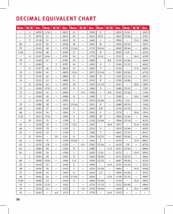
DECIMal EquIvalEnt CHaRt
Nom. M/M Dec. Nom. M/M Dec. Nom. M/M Dec. Nom. M/M Dec. Nom. M/M Dec.— .1 .0039 1/16 — .0625 21 — .1590 K — .2810 9/16 — .5625
— .2 .0079 52 — .0635 20 — .1610 9/32 — .2812 37/64 — .5781
— .3 .0118 51 — .0670 19 — .1660 L — .2900 — 15.0 5906
80 — .0135 50 — .0700 18 — .1695 M — .2950 19/32 — .5937
79 — .0145 49 — .0730 11/64 — .1719 19/64 — .2969 39/64 — .6094
1/64 — .0156 48 — .0760 17 — .1730 N — .3020 5/8 — .6250
— .4 .0157 5/64 — .0781 16 — .1770 5/16 — .3125 — 16.0 .6299
78 — .0160 47 — .0785 15 — .1800 — 8.0 .3150 41/64 — .6406
77 — .0180 — 2 .0787 14 — .1820 O — .3160 21/32 — .6562
— .5 .0197 46 — .0810 13 — .1850 P — .3230 — 17.0 .6693
76 — .0200 45 — .0820 3/16 — .1875 21/64 — .3281 43/64 — .6719
75 — .0210 44 — .0860 12 — .1890 Q — .3320 11/16 — .6875
74 — .0225 43 — .0890 11 — .1910 R — .3390 14/84 — .7031
— .6 .0236 42 — .0935 10 — .1935 11/32 — .3437 — 18.0 .7087
73 — .0240 3/32 — .0937 9 — .1960 S — .3480 23/32 — .7187
72 — .0250 41 — .0960 — 5.0 .1968 — 9.0 .3543 47/64 — .7344
71 — .0260 40 — .0980 8 — .1990 T — .3580 — 19.0 .7480
— .7 .0276 39 — .0995 7 — .2010 23/64 — .3594 3/4 — .7500
70 — .0280 38 — .1015 13/64 — .2031 U — .3680 49/54 — .7656
69 — .0292 37 — .1040 6 — .2040 3/8 — .3750 25/32 — .7812
68 — .0310 36 — .1065 5 — .2055 V — .3770 — 20.0 .7874
1/32 — .0312 7/64 — .1094 4 — .2090 W — .3860 51/64 — .7969
— .8 .0315 35 — .1100 3 — .2130 25/64 — .3906 13/16 — .8125
67 — .0320 34 — .1110 7/32 — .2187 — 10.0 .3937 — 21.0 .8268
66 — .0330 33 — 1130 2 — .2210 X — .3970 53/64 — .8281
65 — .0350 32 — .1160 1 — .2280 Y — .4040 27/32 — .8437
— .9 .0354 — 3.0 .1181 A — .2340 13/32 — .4062 55/64 — .8594
64 — .0360 31 — .1200 15/64 — .2344 Z — .4130 — 22.0 .8661
63 — .0370 1/8 — .1250 — 6.0 .2362 27/64 — .4219 7/8 — .8750
62 — .0380 30 — .1285 B — .2380 — 11.0 .4331 57/64 — .8906
61 — .0390 29 — .1360 C — .2420 7/16 — .4375 — 23.0 .9055
— 1 .0394 28 — .1405 D — .2460 29/64 — .4531 29/32 — .9062
60 — .0400 9/64 — .1406 1/4 — .2500 15/32 — .4687 59/64 — .9219
59 — .0410 27 — .1440 E — .2500 — 12.0 .4724 15/16 — .9375
58 — .0420 26 — .1470 F — .2570 31/64 — .4844 — 24.0 .9449
57 — .0430 25 — .1495 G — .2610 1/2 — .5000 61/64 — .9531
56 — .0465 24 — .1520 17/64 — .2656 — 13.0 .5118 31/32 — .9687
3/64 — .0469 23 — .1540 H — .2660 33/64 — .5156 — 25.0 .9842
55 — .0520 5/32 — .1562 I — .2720 17/32 — .5312 63/64 — .9844
54 — .0550 22 — .1570 — 7.0 .2756 35/64 — .5469 1 25.4 1.000
53 — .0595 — 4.0 .1575 J — .2770 — 14.0 .5512 — — —

31
LIMITED WARRANTY
Seller warrants the goods conform to applicable specifications and drawings and will be manufactured and
inspected according to generally accepted practices of companies manufacturing industrial or aerospace
fasteners. In the event of any breach of the foregoing warranty, Buyer’s sole remedy shall be to return defective
goods (after receiving authorization from Seller) for replacement or refund of the purchase price, at the Seller’s
option. Seller agrees to any freight costs in connection with the return of any defective goods, but any costs
relating to removal of the defective or nonconforming goods or installation of replacement goods shall be
Buyer’s responsibility. SELLER’S WARRANTY DOES NOT APPLY WHEN ANY PHYSICAL OR CHEMICAL CHANGE
IN THE FORM OF THE PRODUCT IS MADE BY BUYER. THE FOREGOING EXPRESS WARRANTY AND REMEDY ARE
EXCLUSIVE AND ARE IN LIEU OF ALL OTHER WARRANTIES AND REMEDIES; ANY IMPLIED WARRANTY AS TO
QUALITY, FITNESS FOR PURPOSE, OR MERCHANTABILITY IS HEREBY SPECIFICALLY DISCLAIMED AND EXCLUDED
BY SELLER. This warranty is void if seller is not notified in writing of any rejection of the goods within one (1)
Year aFter initial use by buyer of any power Riveter or ninety (90) days after initial use of any other product.
Seller shall not be liable under any circumstances for incidental, special or consequential damages arising in whole
or in part from any breach by Seller, AND SUCH INCIDENTAL, SPECIAL, OR CONSEQUENTIAL DAMAGES ARE HEREBY
EXPRESSLY EXCLUDED.
Our policy is one of continuous development. Specifications shown in this document may be subject to changes
introduced after publication.
Cherry® and CherryLOCK® are trademarks of Cherry Aerospace.
note
The properties, strengths, dimensions, installed characteristics and all other information in this catalog is for guidance only to aid in the correct selection of the products described herein and is not intended or implied as part of the warranty. All applications should be evaluated for functional suitability and available samples of the described parts can be requested for installed tests, suitability and evaluations.
attention
Blind fasteners are not always a suitable substitute for solid shank fasteners. Maintenance personnel are reminded that AC 43.13-1A chapter 2, section 3, stipulates: “Do not substitute hollow rivets for solid rivets in load carrying members without specific approval of the application by a representative of the Federal Aviation Administration. Blind rivets may be used in blind locations in accordance with the conditions listed in Chapter 5, provided the edge distances and spacings are not less that the minimum listed in paragraph 99d.”
1224 East Warner Avenue, Santa Ana, CA 92705 voice: 714-545-5511 • fax: 714-850-6093 www.cherryaerospace.com

©Cherry Aerospace Suppliers Federal I.D. Code 11815
CA-1013 Rev: B Date: 12-05-08 CR#: 08-1370
1224 East Warner Avenue, Santa Ana, CA 92705voice: 714-545-5511 • fax: 714-850-6093 www.cherryaerospace.com