Embed Size (px)
Citation preview
8/3/2019 Pasive Bldn at Rajasthan
http://slidepdf.com/reader/full/pasive-bldn-at-rajasthan 1/4
Solar Passive Cooling/Heating of Building at Bikaner in
Rajasthan, IndiaO.P. Jakhar
1, Dr. A.N. Mathur
2
1Department of Mech. Engg. Government Engineering College, Bikaner, Rajasthan, India2Director, GITS, Udaipur, Rajasthan, India
Email of corresponding author: [email protected]
Abstract: The buildings of Bikaner are reasonably
comfortable indoors because of thermal damping by the
massive roofs and walls. However, the average indoor air
temperature (over 24 hours) is about the same as the
average outdoor air temperature. In a light-weight building
without any external glazing and without any ventilation,
the average indoor air temperature is the same as the area
weighted average of the sol-air temperature of external
surfaces, which is bound to be higher than the average
outdoor air temperature. It is an indication of the
effectiveness of the natural cooling methods used at Bikaner
that the indoor temperatures equal the outdoor air
temperature. The indoor temperatures in Bikaner lie just at
the edge of the comfortable range. In other climates with
higher relative humidity it is possible that inspite of good
building design comfortable indoor conditions cannot be
ensured because the average outdoor temperature is too
high. In such climates it is necessary to adopt measures to
lower the average indoor temperature to a level below theoutdoor. Specially designed mud walls are still poplar in the
hamlets (Dhanies) of western Rajasthan to deflect the hot
winds. These are some of the conventional methods of
passive cooling, typical in hot and dry climatic condition.
India has a very diversified climate heating of buildings in
also required especially in upper latitudes and hilly areas
and cooling of buildings is required in lower latitude and
desert areas. Solar passive architecture provides proper
orientation and design of fenestration i.e. doors and windows
to take maximum advantage of sun and wind. For heating
the aim is to admit the sun’s energy as much as possible and
to reduce he loss of heat in the nights. This is achieved by
direct gain through windows, therm-wall, or solarium and
other such means. The heat loss is minimized by the properdesign of walls, by insulation of walls and roof, by night
insulation on windows, by double glazing of windows etc.
Key words: Vary-Therm Wall, indoor temperature, solar
temperature, summer cooling, winter heating
1. Introduction
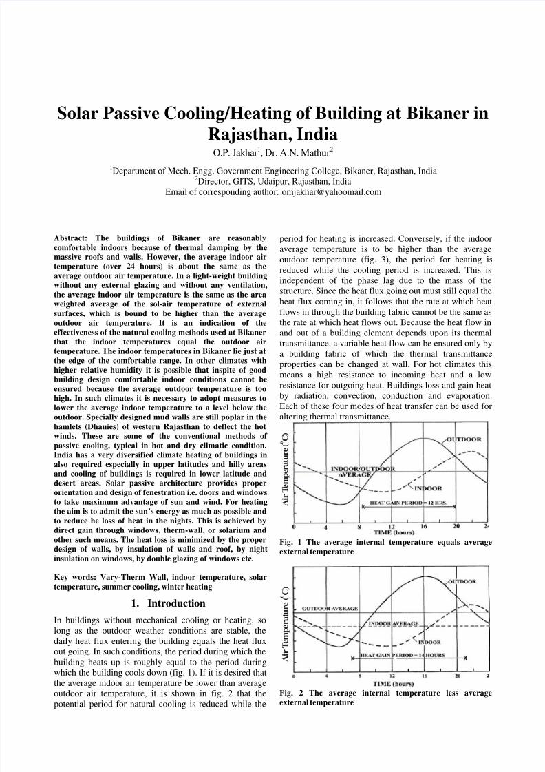
In buildings without mechanical cooling or heating, so
long as the outdoor weather conditions are stable, the
daily heat flux entering the building equals the heat flux
out going. In such conditions, the period during which the
building heats up is roughly equal to the period during
which the building cools down (fig. 1). If it is desired thatthe average indoor air temperature be lower than average
outdoor air temperature, it is shown in fig. 2 that the
potential period for natural cooling is reduced while the
period for heating is increased. Conversely, if the indoor
average temperature is to be higher than the average
outdoor temperature (fig. 3), the period for heating is
reduced while the cooling period is increased. This isindependent of the phase lag due to the mass of the
structure. Since the heat flux going out must still equal the
heat flux coming in, it follows that the rate at which heat
flows in through the building fabric cannot be the same as
the rate at which heat flows out. Because the heat flow in
and out of a building element depends upon its thermal
transmittance, a variable heat flow can be ensured only by
a building fabric of which the thermal transmittance
properties can be changed at wall. For hot climates this
means a high resistance to incoming heat and a low
resistance for outgoing heat. Buildings loss and gain heat
by radiation, convection, conduction and evaporation.
Each of these four modes of heat transfer can be used foraltering thermal transmittance.
A i r T e m p e r a t u r e ( C ) 0
Fig. 1 The average internal temperature equals averageexternal temperature
A i r T e m p e r a t u r e ( C ) 0
Fig. 2 The average internal temperature less average
external temperature
8/3/2019 Pasive Bldn at Rajasthan
http://slidepdf.com/reader/full/pasive-bldn-at-rajasthan 2/4
A i r T e m
p e r a t u r e ( C ) 0
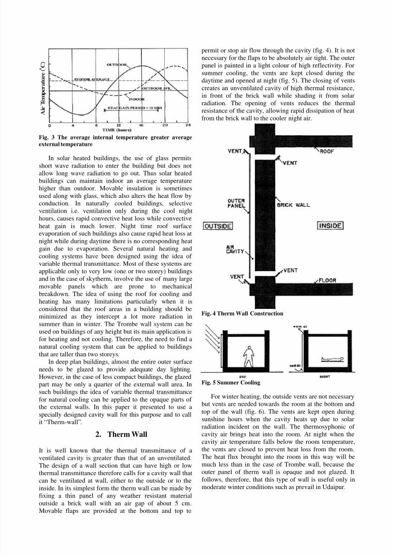
Fig. 3 The average internal temperature greater average
external temperature
In solar heated buildings, the use of glass permits
short wave radiation to enter the building but does not
allow long wave radiation to go out. Thus solar heated
buildings can maintain indoor an average temperature
higher than outdoor. Movable insulation is sometimes
used along with glass, which also alters the heat flow byconduction. In naturally cooled buildings, selective
ventilation i.e. ventilation only during the cool night
hours, causes rapid convective heat loss while convective
heat gain is much lower. Night time roof surfaceevaporation of such buildings also cause rapid heat loss at
night while during daytime there is no corresponding heat
gain due to evaporation. Several natural heating and
cooling systems have been designed using the idea of
variable thermal transmittance. Most of these systems are
applicable only to very low (one or two storey) buildings
and in the case of skytherm, involve the use of many large
movable panels which are prone to mechanical
breakdown. The idea of using the roof for cooling andheating has many limitations particularly when it is
considered that the roof areas in a building should be
minimized as they intercept a lot more radiation in
summer than in winter. The Trombe wall system can be
used on buildings of any height but its main application is
for heating and not cooling. Therefore, the need to find a
natural cooling system that can be applied to buildings
that are taller than two storeys.
In deep plan buildings, almost the entire outer surface
needs to be glazed to provide adequate day lighting.
However, in the case of less compact buildings, the glazed
part may be only a quarter of the external wall area. In
such buildings the idea of variable thermal transmittancefor natural cooling can be applied to the opaque parts of the external walls. In this paper it presented to use a
specially designed cavity wall for this purpose and to call
it “Therm-wall”.
2. Therm Wall
It is well known that the thermal transmittance of a
ventilated cavity is greater than that of an unventilated.
The design of a wall section that can have high or low
thermal transmittance therefore calls for a cavity wall that
can be ventilated at wall, either to the outside or to the
inside. In its simplest form the therm wall can be made byfixing a thin panel of any weather resistant material
outside a brick wall with an air gap of about 5 cm.
Movable flaps are provided at the bottom and top to
permit or stop air flow through the cavity (fig. 4). It is not
necessary for the flaps to be absolutely air tight. The outer
panel is painted in a light colour of high reflectivity. For
summer cooling, the vents are kept closed during thedaytime and opened at night (fig. 5). The closing of vents
creates an unventilated cavity of high thermal resistance,
in front of the brick wall while shading it from solarradiation. The opening of vents reduces the thermal
resistance of the cavity, allowing rapid dissipation of heat
from the brick wall to the cooler night air.
Fig. 4 Therm Wall Construction
Fig. 5 Summer Cooling
For winter heating, the outside vents are not necessary
but vents are needed towards the room at the bottom and
top of the wall (fig. 6). The vents are kept open during
sunshine hours when the cavity heats up due to solar
radiation incident on the wall. The thermosyphonic of
cavity air brings heat into the room. At night when the
cavity air temperature falls below the room temperature,
the vents are closed to prevent heat loss from the room.
The heat flux brought into the room in this way will be
much less than in the case of Trombe wall, because the
outer panel of therm wall is opaque and not glazed. It
follows, therefore, that this type of wall is useful only in
moderate winter conditions such as prevail in Udaipur.
8/3/2019 Pasive Bldn at Rajasthan
http://slidepdf.com/reader/full/pasive-bldn-at-rajasthan 3/4
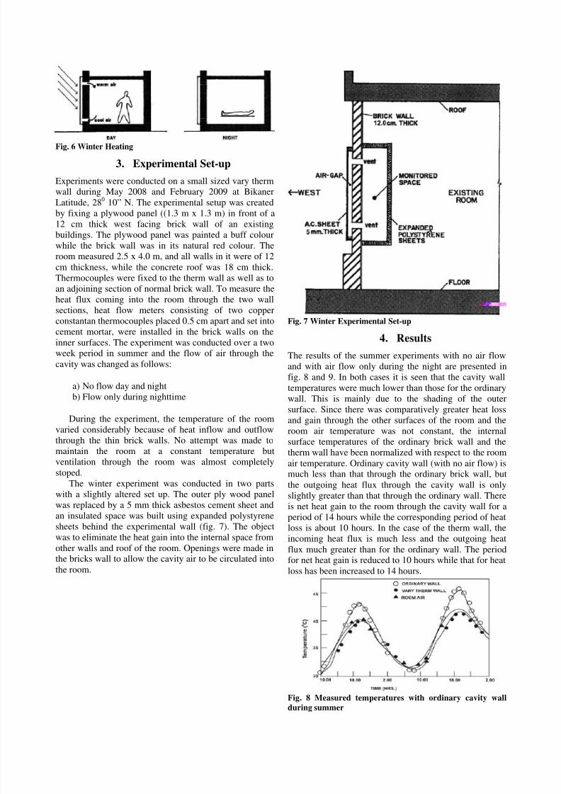
Fig. 6 Winter Heating
3. Experimental Set-up
Experiments were conducted on a small sized vary thermwall during May 2008 and February 2009 at Bikaner
Latitude, 280 10” N. The experimental setup was created
by fixing a plywood panel ((1.3 m x 1.3 m) in front of a
12 cm thick west facing brick wall of an existing
buildings. The plywood panel was painted a buff colour
while the brick wall was in its natural red colour. The
room measured 2.5 x 4.0 m, and all walls in it were of 12
cm thickness, while the concrete roof was 18 cm thick.
Thermocouples were fixed to the therm wall as well as toan adjoining section of normal brick wall. To measure the
heat flux coming into the room through the two wall
sections, heat flow meters consisting of two copper
constantan thermocouples placed 0.5 cm apart and set into
cement mortar, were installed in the brick walls on the
inner surfaces. The experiment was conducted over a twoweek period in summer and the flow of air through the
cavity was changed as follows:
a) No flow day and night
b) Flow only during nighttime
During the experiment, the temperature of the roomvaried considerably because of heat inflow and outflow
through the thin brick walls. No attempt was made to
maintain the room at a constant temperature but
ventilation through the room was almost completely
stoped.
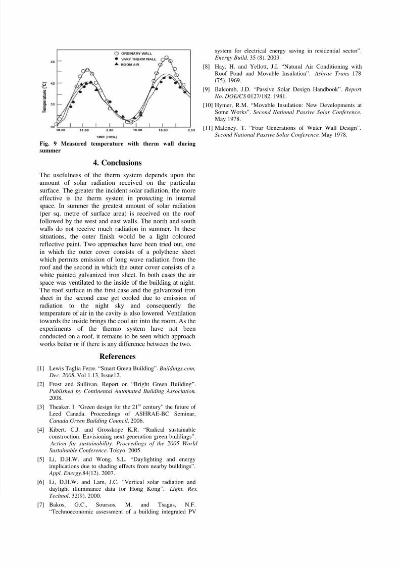
The winter experiment was conducted in two parts
with a slightly altered set up. The outer ply wood panel
was replaced by a 5 mm thick asbestos cement sheet and
an insulated space was built using expanded polystyrene
sheets behind the experimental wall (fig. 7). The object
was to eliminate the heat gain into the internal space from
other walls and roof of the room. Openings were made in
the bricks wall to allow the cavity air to be circulated intothe room.
Fig. 7 Winter Experimental Set-up
4. Results
The results of the summer experiments with no air flow
and with air flow only during the night are presented in
fig. 8 and 9. In both cases it is seen that the cavity wall
temperatures were much lower than those for the ordinary
wall. This is mainly due to the shading of the outer
surface. Since there was comparatively greater heat loss
and gain through the other surfaces of the room and theroom air temperature was not constant, the internal
surface temperatures of the ordinary brick wall and the
therm wall have been normalized with respect to the room
air temperature. Ordinary cavity wall (with no air flow) ismuch less than that through the ordinary brick wall, but
the outgoing heat flux through the cavity wall is only
slightly greater than that through the ordinary wall. There
is net heat gain to the room through the cavity wall for a
period of 14 hours while the corresponding period of heat
loss is about 10 hours. In the case of the therm wall, the
incoming heat flux is much less and the outgoing heat
flux much greater than for the ordinary wall. The periodfor net heat gain is reduced to 10 hours while that for heat
loss has been increased to 14 hours.
Fig. 8 Measured temperatures with ordinary cavity wallduring summer
8/3/2019 Pasive Bldn at Rajasthan
http://slidepdf.com/reader/full/pasive-bldn-at-rajasthan 4/4
Fig. 9 Measured temperature with therm wall during
summer
4. Conclusions
The usefulness of the therm system depends upon the
amount of solar radiation received on the particular
surface. The greater the incident solar radiation, the more
effective is the therm system in protecting in internalspace. In summer the greatest amount of solar radiation
(per sq. metre of surface area) is received on the roof
followed by the west and east walls. The north and south
walls do not receive much radiation in summer. In these
situations, the outer finish would be a light coloured
reflective paint. Two approaches have been tried out, one
in which the outer cover consists of a polythene sheet
which permits emission of long wave radiation from the
roof and the second in which the outer cover consists of a
white painted galvanized iron sheet. In both cases the air
space was ventilated to the inside of the building at night.
The roof surface in the first case and the galvanized iron
sheet in the second case get cooled due to emission of radiation to the night sky and consequently thetemperature of air in the cavity is also lowered. Ventilation
towards the inside brings the cool air into the room. As the
experiments of the thermo system have not been
conducted on a roof, it remains to be seen which approach
works better or if there is any difference between the two.
References
[1] Lewis Taglia Ferre. “Smart Green Building”. Buildings.com,
Dec. 2008, Vol 1.13, Issue12.
[2] Frost and Sullivan. Report on “Bright Green Building”.
Published by Continental Automated Building Association.
2008.
[3] Theaker. I. “Green design for the 21st century” the future of
Leed Canada. Proceedings of ASHRAE-BC Seminar,
Canada Green Building Council, 2006.
[4] Kibert. C.J. and Grosskope K.R. “Radical sustainable
construction: Envisioning next generation green buildings”.
Action for sustainability. Proceedings of the 2005 World
Sustainable Conference. Tokyo. 2005.
[5] Li, D.H.W. and Wong. S.L. “Daylighting and energy
implications due to shading effects from nearby buildings”.
Appl. Energy.84(12). 2007.
[6] Li, D.H.W. and Lam, J.C. “Vertical solar radiation and
daylight illuminance data for Hong Kong”. Light. Res.
Technol. 32(9). 2000.[7] Bakos, G.C., Soursos, M. and Tsagas, N.F.
“Technoeconomic assessment of a building integrated PV
system for electrical energy saving in residential sector”.
Energy Build . 35 (8). 2003.
[8] Hay, H. and Yellott, J.I. “Natural Air Conditioning with
Roof Pond and Movable Insulation”. Ashrae Trans. 178
(75). 1969.
[9] Balcomb, J.D. “Passive Solar Design Handbook”. Report
No. DOE/CS 0127/182. 1981.[10] Hymer, R.M. “Movable Insulation: New Developments at
Some Works”. Second National Passive Solar Conference.
May 1978.
[11] Maloney. T. “Four Generations of Water Wall Design”.
Second National Passive Solar Conference. May 1978.


![Constructii Pasive Cu Verb Modal[1]](https://img.pdfslide.us/doc/110x75/55cf8571550346484b8e0e3b/constructii-pasive-cu-verb-modal1.jpg)