Embed Size (px)
Citation preview

For safe and reliable operation, it is essential to read the user,s manual carefullybefore using this equipment.
2006 11A SPrinted in Japan
PARTICLECLUTCHES/BRAKESOur clutches and brakes
used in various equipment including industrial equipment,
information equipment and recreation facilities play
an important part in automation or
motion control systems.
SHINKO ELECTRIC CO., LTD.Please note that our former company name or logo may be printed in this catalog.
Formerly SHINKO ELECTRIC CO., LTD.
Formerly SHINKO ELECTRIC CO., LTD.
E75-120CODE
Formerly
Shiba NBF Tower, 1-30, Shiba-daimon 1-chome, Minato-ku, Tokyo, 105-8564, JapanTEL +81-3-5473-1826 FAX +81-3-5473-1845
SINFONIA TECHNOLOGY CO., LTD. continually upgrades and improves its products. Actual features and specifications may therefore differ slightly from those described in this catalog.
96 Robinson Road, #13-02 SIF Building, Singapore 068899TEL +65-6223-6122 FAX +65-6225-2729
Graha Paramita 8th Floor Suite E Jl. Denpasar Raya Block D2 KAV. 8 Kuningan, Jakarta 12940, IndonesiaTEL: 021-252-3606 (hunting) FAX: 021-252-3608
Room3006, Building B Far East International Plaza, No 317, Xian Xia Road, Changning District, Shanghai, ChinaZip Code:200051TEL +86-21-6275-0606 FAX +86-21-3209-8975
http://www.sinfo-t.jp
For safe and reliable operation, it is essential to read the user,s manual carefullybefore using this equipment.
2007 4A SPrinted in Japan
Our clutches and brakes
used in various equipment including industrial equipment,
information equipment and recreation facilities play
an important part in automation or
motion control systems.
We have a new slogan in Japan; “ECOing” a combination of “eco” and “ing” . This is to promote eco-friendly technological development and manufacturing. Our ecological activities are of course not limited to Japan and practiced in many countries around the world.

1 2
We use a special magnetic powder to transmit and control the torque on this series of clutches/brakes. The original powder and advanced structural design create incomparable performance in torque control and slip usage. Our unique materials and manufacturing expertise produce a high quality, nearly spherical powder, which dramatically improves the performance and reliability of our product, truly making this the ideal powder clutch/brake.
1. High precision torque over a wide range of valuesBy using efficient magnetic circuitry, the transmitted torque can be varied between 3% and 100% of maximum rated torque.
2. Stable torque and long operating lifeThe ideal spherical powder obtains stable torque and smooth slip operation.
3. High thermal radiation capabilityUsing a heat resistant powder, and a structure with high thermal radiation capability, our devices are capable of heavy continuous slip operation. slip operation.Heat pipe powder brake is incredible thermal radiation capability which outperforms water-cooled models.
4. Non-shock, smooth linkage and brakeAchieve an excellent buffer effect with its constant torque and smooth slip torque.
5. Non-abrasive powder and silent operationUnlike abrasive clutches/brakes there is no wearing powder, and silent operation is possible since there is no linkage sound.
6. Rapid responseThe generated magnetic flux operates instantaneously as the effective flux, providing rapid torque response.
Features
Models Names
List of Models
Nominal number
Model symbolPOC: Shaft type / Naturally cooled clutchPHC: Hollow center type / Self-ventilating clutchPMC: Micro type / Naturally cooled clutchPOB: Shaft type / Naturally cooled brakePHB: Hollow center type / Naturally cooled brakePRB-H: Hollow center type / Naturally cooled brake (with side fin)PTB: Shaft type / Heat pipe cooled brake
Type
Clutch
Appearance
Type
Appearance
Brake
POCNaturally cooled
POBNaturally cooled
PHBNaturally cooled
PRB-HNaturally cooled (with side fin)
PTBHeat pipe cooled
PHC-RSelf-ventilating
PMCNaturally cooled
Particle Clutches/Brakes
Particle typeSeries
POB-10
Shaft type Hollow center type
Shaft type Shaft typeHollow center type Hollow center type
Micro type
3 4
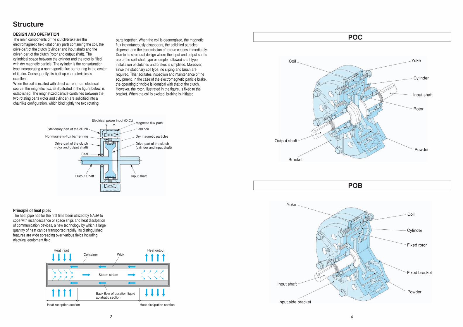
DESIGN AND OPEFIATIONThe main components of the clutch/brake are the electromagnetic field (stationary part) containing the coil, the drive-part of the clutch (cylinder and input shaft) and the driven-part of the clutch (rotor and output shaft). The cylindrical space between the cylinder and the rotor is filled with dry magnetic particle. The cylinder is the nonsaturation type incorporating a nonmagnetic-flux barrier ring in the center of its rim. Consequently, its built-up characteristics is excellent.When the coil is excited with direct current from electrical source, the magnetic flux, as illustrated in the figure below, is established. The magnetized particle contained between the two rotating parts (rotor and cylinder) are solidified into a chainlike configuration, which bind tightly the two rotating
parts together. When the coil is deenergized, the magnetic flux instantaneously disappears, the solidified particles disperse, and the transmission of torque ceases immediately.Due to its structural design where the input and output shafts are of the split-shaft type or simple hollowed shaft type, installation of clutches and brakes is simplified. Moreover, since the stationary coil type, no sliping and brush are required. This facilitates inspection and maintenance of the equipment. In the case of the electromagnetic particle brake, the operating principle is identical with that of the clutch. However, the rotor, illustrated in the figure, is fixed to the bracket. When the coil is excited, braking is initiated.
Principle of heat pipe:The heat pipe has for the first time been utilized by NASA to cope with incandescence or space ships and heat dissIpation of communication devices, a new technology by which a large quantity of heat can be transported rapidly. Its distinguished features are wide spreading over various fields including electrical equipment field.
Structure
POC
POB
Stationary part of the clutch
Seal
Drive-part of the clutch(rotor and output shaft)
Magnetic-flux path
Field coil
Input shaftOutput Shaft
Dry magnetic particles
Drive-part of the clutch(cylinder and input shaft)
Electrical power input (D.C.)
Heat outputHeat input
Steam striam
Container Wick
Back flow of opration liquidabiabatic section
Heat reception section Heat dissipation section
Coil
Output shaft
Rotor
Yoke
Cylinder
Input shaft
Powder
Bracket
Yoke
Coil
Cylinder
Fixed rotor
Fixed bracket
Powder
Input shaft
Input side bracket
Nonmagnetic-flux barrier ring

5 6
PMC
PRB-H
PHC-R
PHB
Yoke Fan
CoilInput side bracket
Cylinder
Rotor
Output hub
Input hub
Powder
Output side bracket
CylinderYoke
Coil
Input side bracket
Fixed rotor
Fixed bracket
PowderHub
Yoke
Coil
Output shaft
Cylinder
Rotor
PowderInput hub
Side plate A
Yoke
Coil
Rotor
Powder
Side plate B

7 8
1. To use in the state of continuous slipTo use in the state of continuous slip with a constant torque and a constant rpm for tension control of dummy loads and start up windlng brake, the continuous slip power is calculated by the following formula. Here, it is possible to use the required brake torque by adjustirlg the rated torque in the range 3~100%.
Ps=0.103xTxn (W) T: Set torque of brake (Nm) n: rpm of brake shah (r/min)
Example (Conditions) Set torque of brake: T=35 (Nm) rpm of brake:n=65(r/min) Select the brake for the above state.
(1) Temporarily select the one having the rated torqur 50 Nm from the set torque 35Nm.
(2) Calculate the slip power. Ps=0.103×35×65≠234WThe type having the slip power larger than 234W is required.
(3) The type may be selected from the allowable slip power diagram:For the shaft type, the allowable slip power of POB-10 is 270W (234W<270W). Therefore, POB-10 may be used.
(4) The simple selection table below with the continuous slip power considered is based on rpm of 1000 r/min. Therefore, it is required to determine the feasibility of use at this rpm by an allowable slip power diagram.
2. To make tension controlTo make constant tension control with continuous slip applying a start up winding brake, calculation is made using the following formulae:
Principal data dimensions of application conditions necessary for exarmination: 1. Line speed: Maximum Vmax. Minimum Vmin (m/min) 2. Start up wlndlng dia: Maximum Dmax. Minimum Dmin (mm ø) 3. Set tension: Maximum Fmax, Minimum Fmin (N)
1) For start up winding brakeTo make start up winding control applying the electromagnet powder brake, following points should be examined:
1) For start up winding brakeTo make start up winding control applying the electromagnet powder clutch, following points should be examined:
(Example)[Conditions]1.Line speed: Maximum Vmax=160m/min Minimum Vmin=85m/min2.Start up winding dia.: Maximum Dmax=ø900mm Minimum Dmin=ø150mm3.Settension: F=140(N)constantSelect the brake for the above state.
(Example)[Conditions]1.Line speed: Maximum Vmax=30m/min Maximum Dmax=ø650mm Minimum Dmin=ø150mm3.Settension: F=120(N)constantSelect the clutch for the above state.
Slip power of 367W or more and torque of 63Nm or more may be required.
(8) The allowable slip power of POB-20 is 430W (367W<430W, 63 Nm<200 Nm) according to the Allowable Slip Power Diagram (see page 234), so POB-20 is available.
(2) Required brake torque (T) at final stage and rpm of brake (N)
(3) Maximum rpm (Nmax)
T= ×10–3(Nm)Fmax×Dmax2
N= ×103(r/min)Vmaxπ×Dmax
Nmax= ×103(r/min)Vmaxπ×Dmin
(4) Minimum rpm (Nmin)
Nmin= ×103(r/min)Vminπ×Dmin
(5) Minimum brake torque (Tmin)
T= ×10–3(Nm)Fmin×Dmin2
Tmin= ×10–3(Nm)Fmin×Dmin2
(6) Maximum brake torque (Tmax)
Tmax= ×10–3(Nm)Fmax×Dmax2
(7) Maximum slip power (Pmax)
Pmax= 0.0164×Fmax×Vmax (W)
N= ×103(r/min)Vminπ×Dmin
(1) Required brake torque (T) at start up and rpm of brake (N)
(2) Required brake torque (T) at final stage and rpm of brake (N)
(3) Maximum rpm (Nmax)
T= ×10–3=63(Nm)140×9002
N= ×103=56.6(r/min)160π×900
T= ×10–3=9(Nm)120×1502
Ns= ×103=64(r/min)30π×150
Nmax= ×103=339.5(r/min)160π×150
(4) Minimum rpm (Nmin)
Nmin= ×103=30.1(r/min)85π×900
(5) Minimum brake torque (Tmin)
T= ×10–3=10.5(Nm)140×1502
Tmin= ×10–3=10.5(Nm)140×1502
(6) Maximum brake torque (Tmax)
Tmax= ×10–3=63(Nm)140×9002
(7) Maximum slip power (Pmax)
Pmax= 0.0164×140×160=367 (W)
N= ×103=339.5(r/min)160π×150
(1) Required brake torque (T) at start up and rpm of brake (N)
Simple Selection Table with Slip Power Considered(1000 r/min)
(2) Required clutch torque (T) at final stage and rpm of output shaft (Ns)
(3) Maximum rpm (Nmax)
T= ×10–3(Nm)Fmax×Dmin2
Ns= ×103(r/min)Vmaxπ×Dmin
Nmax= ×103(r/min)Vmaxπ×Dmin
(4) Minimum rpm (Nmin)
Nmin= ×103(r/min)Vminπ×Dmin
(5) Minimum clutch torque (Tmin)
T= ×10–3(Nm)Fmax×Dmax2
Tmin= ×10–3(Nm)Fmin×Dmin2
(6) Maximum clutch torque (Tmax)
Tmax= ×10–3(Nm)Fmax×Dmax2
(7) Maximum slip power (Pmax)
Ns= ×103(r/min)Vmaxπ×Dmax
(1) Required clutch torque (T) at start up and rpm of output shaft (Ns)
(1) Required clutch torque (T) at start up and rpm of output shaft (Ns)
N0
NmaxDmaxDminPmax= 0.0164×Fmax×Vmax× × –1( ) (W)
N0 : rpm of clutch input shaft
Cooling System
Rated Torque
(Nm)
Model
Allowable Slip Power (W)
Natural Cooling System
Natural Cooling System
190080045029018013084
190080045029018013084
4002001005025126
POC
POB
CIutch or Brake Selection Guide
Controller
Detector

9 10
(2) Required clutch torque (T) at final stage and rpm of output shaft (Ns)
(3) Maximum rpm (Nmax)
Nmax= ×103=64(r/min)30≠×150
(4) Minimum rpm (Nmin)
Nmin= ×103=14.7(r/min)30≠×650
(5) Minimum clutch torque (Tmin)
T= ×10–3=39(Nm)120×6502
Tmin= ×10–3=9(Nm)120×1502
(6) Maximum clutch torque (Tmax)
Tmax= ×10–3=39(Nm)120×6502
(7) Maximum slip power (Pmax)
Ns= ×103=14.7(r/min)30≠×650
9464
650150Pmax= 0.0164×30×120× × –1( ) =317(W)
Since the relative rpm exceeding 30 r/min of the maximum rpm (Nmax) is required for rpm of clutch input shaft No, No is temporarily set to 94 r/min (64 + 30) here.
Slip power of 317W or more and torque of 39Nm or more are required.
(8) The allowable slip power of POC-20 is 430W (317W<430W, 39 Nm<200 Nm) according to the Allowable Slip Power Diagram (see page 11), so POC-20 is available.
3) To use as torque limiterTo prevent overload of the motor or power engine as well as damage to the machine /product, the clutch is slipped by using the constant torque characteristic of an electromagnetic particle clutch when a torque exceeding a specified one is applied. Calculation is made using the following formula:
4) For simple ON-OFF use(1) Selecting clutch capacityWhen selecting a sutitable electromotor, choose one whose size is adequate for the torque value the clutch shaft must adjusted from 3 to 100% by controlling the exciting current.
Equivalent slip power
Pave= Ps2×t1t
(W)
Pave= (204)2×110
=64.5(W)
Ps=0.103×Tc×ni (W)
Ps=0.103×1.1×1800=204 (W)
(3) The allowable slip power of POC-0.6A is 84W (64.5W<84W, the control range of POC-0.6A is 0.18 to 6 Nm, <3-100%>), so POS-0.6A is available.
(2) Equivalent slip power (Pave)
(1) Convert torque to the clutch shaft. (T)
t1: Slip time during 1 cycle (S)t: Time of 1 cycle (S)Tc: Set torque of clutch (Nm)ni: Relative rpm (r/min)
T=12× 110
5055× =1.1 (Nm)
(2) Selecting brake capacity
(3) Engaging energy rate or braking energy rateWhen using for starting and stopping machinery, the engaging frequency must be considered and the engaging energy or the braking energy rate must be examined.
(Braking energy rate)
(Engaging energy rate)
T= ×Kt (Nm)9550×Pn
Kt : Safety coefficient when using clutch.
T= ×B (Nm)9550×Pn
B : Brake rate – 80% or 150% is normally used.
E= (W)J×ni2182
TcTc – TR
× N60
×
E= (W)J×ni2182
TcTc + TR
× N60
×
Allowable engaging energy rate characteristics
M R
Example
(Condition)
Powder clutch
Reduction ratio
Number of teeth: 50
Tighten screw
Number of teeth: 55
Tightening torque12 Nm
Cycle: 10 sec. (slip for 1 sec. only, motor stop for 9 sec.)
0.75kW 4P
1800r/min
110
0
50
100
150
200
300
400
500
600
700800
900
1000
1100
1200
1300
1400
1500
1600
500 1000 1500 1800
POC_0.6APOC_0.3
POC_1.2A
POC_2.5A
POC_5APOC_10
POC_20
POC_40
POC_80
Allo
wab
le e
ngag
ing
ener
gy r
ate
(W
)
Input speed (r/min)
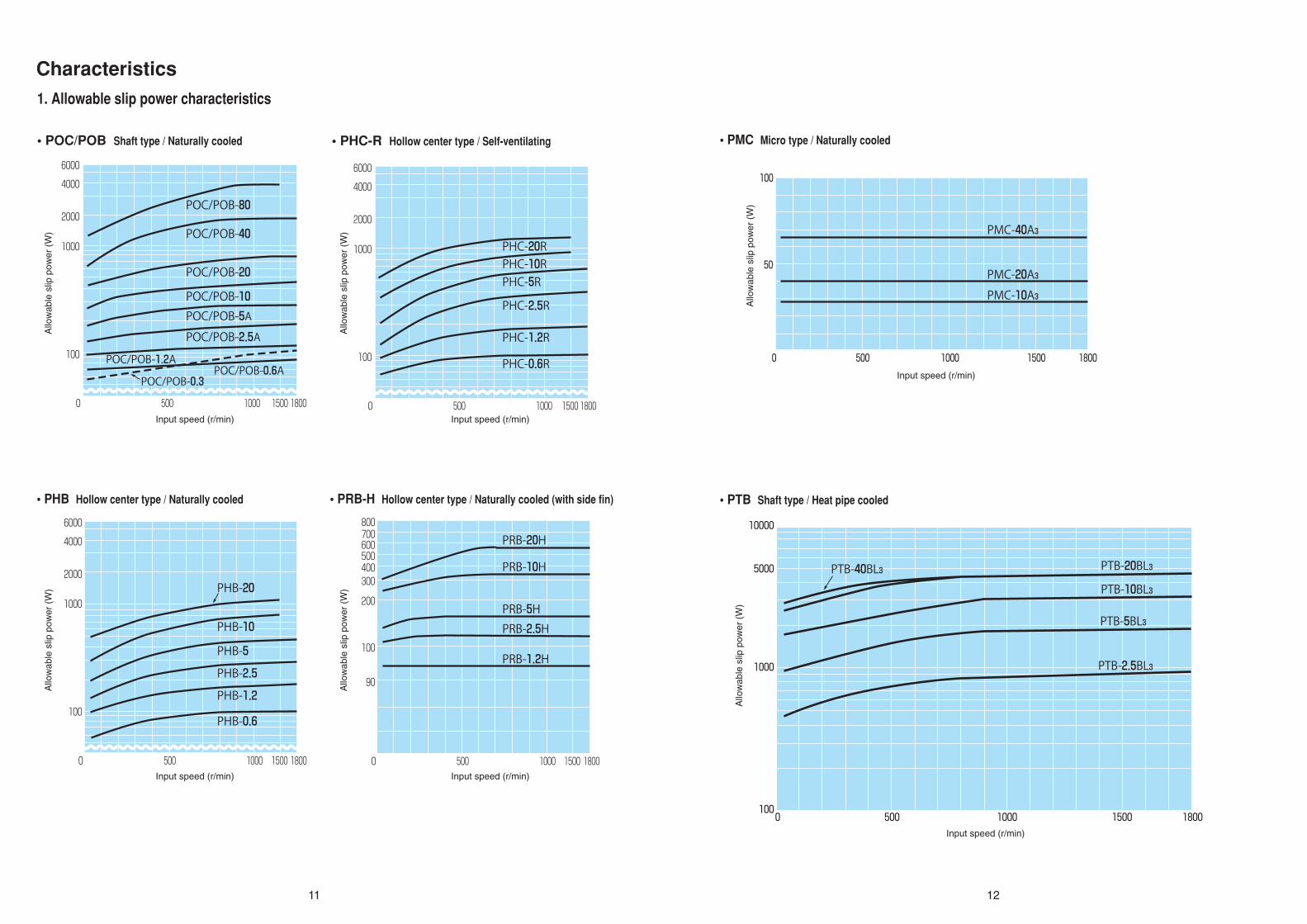
1. Allowable slip power characteristics
Characteristics
• POC/POB Shaft type / Naturally cooled • PHC-R Hollow center type / Self-ventilating
• PHB Hollow center type / Naturally cooled • PRB-H Hollow center type / Naturally cooled (with side fin) • PTB Shaft type / Heat pipe cooled
• PMC Micro type / Naturally cooled
11 12
0
100
1000
2000
4000
6000
500 1000 18001500
POC/POB-80
PHC-20RPHC-10RPHC-5R
PHC-2.5R
PHC-1.2R
PHB-20
PHB-10
PHB-5
PHB-2.5
PHB-1.2
PHB-0.6
PHC-0.6R
PRB-20H
PRB-10H
PRB-5HPRB-2.5H
PRB-1.2H
POC/POB-40
POC/POB-20
POC/POB-10POC/POB-5APOC/POB-2.5A
POC/POB-1.2APOC/POB-0.6A
POC/POB-0.3
0
100
1000
2000
4000
6000
500 1000 18001500 0
90
100
200
300400500600700800
500 1000 18001500
0
100
1000
2000
4000
6000
500 1000 18001500
PMC-40A3
PMC-20A3PMC-10A3
0 500 1000 1500 1800
100
50
0 500 1000 1500 1800100
1000
5000
10000
PTB-40BL3 PTB-20BL3
PTB-10BL3
PTB-5BL3
PTB-2.5BL3
Allo
wab
le s
lip p
ower
(W
)
Input speed (r/min)
Allo
wab
le s
lip p
ower
(W
)
Input speed (r/min)
Allo
wab
le s
lip p
ower
(W
)
Input speed (r/min)
Allo
wab
le s
lip p
ower
(W
)
Input speed (r/min)
Allo
wab
le s
lip p
ower
(W
)
Input speed (r/min)
Allo
wab
le s
lip p
ower
(W
)
Input speed (r/min)
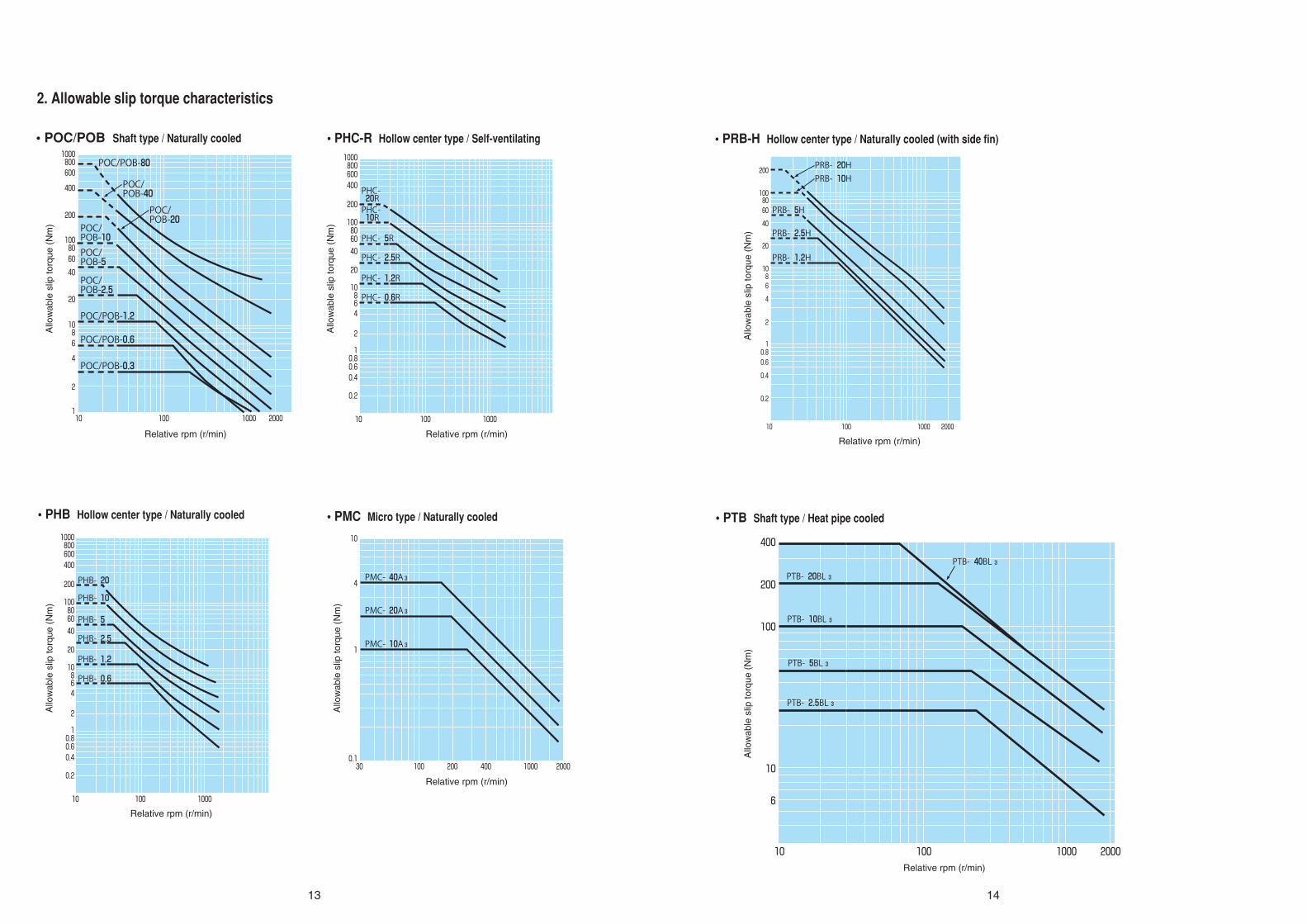
2. Allowable slip torque characteristics
• POC/POB Shaft type / Naturally cooled • PHC-R Hollow center type / Self-ventilating
• PHB Hollow center type / Naturally cooled
• PRB-H Hollow center type / Naturally cooled (with side fin)
• PTB Shaft type / Heat pipe cooled• PMC Micro type / Naturally cooled
13 14
10 100 1000 2000
6
10
100
200
400
PTB- 40BL 3
PTB- 20BL 3
PTB- 10BL 3
PTB- 5BL 3
PTB- 2.5BL 3
POC/POB-80
POC/ POB-40
POC/ POB-10POC/ POB-5
POC/ POB-2.5
POC/POB-1.2
POC/POB-0.6
POC/POB-0.3
POC/ POB-20
1000 2000100101
2
4
6810
20
40
6080100
200
400
6008001000
100010010
10.80.60.4
0.2
2
46810
20
406080100
200
4006008001000
PHB- 0.6
PHB- 1.2
PHB- 2.5
PHB- 5
PHB- 10
PHB- 20
30 100 200 400 1000 2000
1
10
0.1
4PMC- 40A 3
PMC- 20A 3
PMC- 10A 3
1000 200010010
10.80.6
0.4
0.2
2
4
68
10
20
40
6080
100
200
PRB- 2.5H
PRB- 5H
PRB- 10HPRB- 20H
PRB- 1.2H
100010010
10.80.60.4
0.2
2
468
10
20
406080
100
200
400600800
1000
PHC- 10R
PHC- 5R
PHC- 2.5R
PHC- 1.2R
PHC- 0.6R
PHC- 20R
Allo
wab
le s
lip to
rque
(N
m)
Relative rpm (r/min)
Allo
wab
le s
lip to
rque
(N
m)
Relative rpm (r/min)
Allo
wab
le s
lip to
rque
(N
m)
Relative rpm (r/min)
Allo
wab
le s
lip to
rque
(N
m)
Relative rpm (r/min)
Allo
wab
le s
lip to
rque
(N
m)
Relative rpm (r/min)
Allo
wab
le s
lip to
rque
(N
m)
Relative rpm (r/min)

As the cause of drag torque, the effect of clutch bearing loss, seal part friction loss, windage loss, or residual magnetism is suspected. Drag torque has no effect during continuous slip operation, but large drag torque exerts an adverse effect such as load drag during ON/OFF application. SINFONIA TECHNOLOGY CO., LTD. reduces drag torque to approximately 1% of the rated torque in consideration of the above.(Since the value of drag torque varies depending on the model, contact us separately.)
Exciting current – Torque characteristic
Relative rpm – Torque characteristic
Type: POC-0.6ASpeed: 1000r/minRated voltage: DC-24VRated current: 0.792A
Type: POC-5ARated voltage: DC-24VRated current: 1.875A
Drag torque characteristic
15 16
0
2
4
6
8
10
12
14
0 0.2 0.4 0.6 0.8 1.0
0
20
40
60
80
100
0 500 1000 1500 2000
25%
50%
75%
100%
125%
Exciting current
Exciting current (A)
Relative rpm (r/min)
Tor
que
(Nm
)
Tor
que
(Nm
)
0.6321
0.8TR 0.632Tmax
Time
Time
Exciting current
Drag torque
0.368Tmax0.1TR
Saturation torque Tmax
Saturation torque constant
Coil constant
80% torque start time
Torque exit time

• POC-0.3 • POC-0.6A • POC-1.2A
• POC-2.5A • POC-5A • POC-10
• POC-20 • POC-40 • POC-80
• POB-0.3 • POB-0.6A • POB-1.2A
• POB-2.5A • POB-5A • POB-10
• POB-20 • POB-40 • POB-80
Current – Torque characteristics
17 18
0 0.5 1.0
5
10
15
Torque (Nm)
Current(A) 0 0.3 0.6 0.9 1.2
3
4
5
2
1
Torque (Nm)
Current(A)
0 2.0 2.51.51.00.5 3.53.0 4.0
100
200
300
Torque (Nm)
Current(A) 0 1 2 3 4 5 6
5
10
15
Torque (Nm)
Current(A)
0 2 4 6
200
400
600
800
1000
1200
1400
Torque (Nm)
Current(A)
0 0.5 1.0
5
10
15
20
Torque (Nm)
Current(A)
0.8
0 1.0 2.0
10
20
30
40
50
60
70
80
Torque (Nm)
Current(A) 0 0.5 1.0 1.5 2.0 2.5 3.0
50
100
150
Torque (Nm)
Current(A)
1.970 1.0 2.0
10
20
30
Torque (Nm)
Current(A)
1.12
0.55
0 0.5 1.0
5
10
15
0.8
0 1.0 2.0
10
20
30
1.12
0 1.0 2.0
10
20
30
40
50
60
70
80
1.97
0.85
2.20
4.583.832.75
Torque (Nm)
Current(A) 0 0.3 0.6 0.9 1.2
3
4
5
2
1
Torque (Nm)
Current(A)
0 2.0 2.51.51.00.5 3.53.0 4.0
100
200
300
Torque (Nm)
Current(A) 0 1 2 3 4 5 6
5
10
15
Torque (Nm)
Current(A)
0 2 4 6
200
400
600
800
1000
1200
1400
Torque (Nm)
Current(A)
0 0.5 1.0
5
10
15
20
Torque (Nm)
Current(A)
Torque (Nm)
Current(A) 0 0.5 1.0 1.5 2.0 2.5 3.0
50
100
150
Torque (Nm)
Current(A)
Torque (Nm)
Current(A)
0.55 0.85
2.20
4.583.832.75

• PMC-10A3 • MC-20A3
• POB-1.2A
• PMC-40A3
• PRB-1.2H • PRB-2.5H
• PRB-10H • PRB-20H
• PRB-5H
19 20
0 0.1 0.2 0.3 0.4 0.5 0.6
0.5
1
1.5
Torque (Nm)
Current(A)
0.56
0 0.1 0.2 0.3 0.4 0.5 0.6 0.7
1
2
3
Torque (Nm)
Current(A)
0.62
0 0.1 0.2 0.3 0.4 0.5 0.6 0.7 0.8
1
2
3
4
5
Torque (Nm)
Current(A)
0.75
0 0.5 1.0
10
20
40
30
Torque (Nm)
Current(A) 0 0.5 1.0
10
20
40
30
Torque (Nm)
Current(A) 0 0.5 1.0 1.5
25
50
100
75
Torque (Nm)
Current(A)
0.63
1.33 1.58
0.77 1.02
0 0.5 1.0 1.5
50
100
200
250
150
Torque (Nm)
Current(A)
0 0.5 1.0 1.5 2.0
50
100
200
250
150
Torque (Nm)
Current(A)

TYPE Max speed(r/min)
J(kg ㎡)Input side Output side
POC-0.3 1800 5.40×10⁻⁴ 2.01×10⁻⁴
POC-0.6A 1800 7.30×10⁻⁴ 2.40×10⁻⁴
POC-1.2A 1800 1.28×10⁻³ 4.40×10⁻⁴
POC-2.5A 1800 4.10×10⁻³ 1.63×10⁻³
POC-5A 1800 1.05×10⁻² 4.80×10⁻³
POC-10 1800 4.40×10⁻² 1.84×10⁻²
POC-20 1800 9.40×10⁻² 5.00×10⁻²
POC-40 1800 2.50×10⁻¹ 1.30×10⁻¹
POC-80 1500 9.90×10⁻¹ 6.40×10⁻¹
TYPE Max speed(r/min)
J(kg ㎡)Input side
POB-0.3 1800 0.54×10⁻³
POB-0.6A 1800 7.30×10⁻⁴
POB-1.2A 1800 1.28×10⁻³
POB-2.5A 1800 4.10×10⁻³
POB-5A 1800 1.05×10⁻²
POB-10 1800 4.40×10⁻²
POB-20 1800 9.40×10⁻²
POB-40 1800 2.50×10⁻¹
POB-80 1500 9.90×10⁻¹
TYPE Max speed(r/min)
J(kg ㎡)Input side Output side
PHC-0.6R 1800 9.40×10⁻⁴ 3.00×10⁻⁴
PHC-1.2R 1800 1.65×10⁻³ 7.20×10⁻⁴
PHC-2.5R 1800 5.30×10⁻³ 2.08×10⁻³
PHC-5R 1800 1.36×10⁻² 5.80×10⁻³
PHC-10R 1500 6.00×10⁻² 2.60×10⁻²
PHC-20R 1500 1.27×10⁻² 5.50×10⁻²
TYPE Max speed(r/min)
J(kg ㎡)Input side
PHB-0.6 1800 7.50×10⁻⁴
PHB-1.2 1800 1.33×10⁻³
PHB-2.5 1800 4.50×10⁻³
PHB-5 1800 1.07×10⁻²
PHB-10 1800 3.70×10⁻²
PHB-20 1800 9.40×10⁻²
TYPE Max speed(r/min)
J(kg ㎡)Input side Output side
PMC-10A3 1800 0.700 8.50×10⁻²
PMC-20A3 1800 1.210 2.20×10⁻¹
PMC-40A3 1800 3.350 1.090
TYPE Max speed(r/min) J(kg ㎡)
PRB-1.2H 1800 1.10×10⁻³
PRB-2.5H 1800 1.70×10⁻³
PRB-5H 1800 4.78×10⁻²
PRB-10H 1800 1.59×10⁻²
PRB-20H 1800 4.70×10⁻²
TYPE Max speed(r/min) J(kg ㎡)
PTB-2.5BL3 1800 4.10×10⁻³
PTB-5BL3 1800 1.05×10⁻²
PTB-10BL3 1800 4.40×10⁻²
PTB-20BL3 1800 9.40×10⁻²
PTB-40BL3 1800 2.50×10⁻¹
Maximum rpm moment of enertia
• PTB-2.5BL3 • PTB-5BL3
• PTB-10BL3
• PTB-40BL3
• PTB-20BL3
• POC Shaft type / Naturally cooled • POB Shaft type / Naturally cooled
• PHC-R Hollow center type / Self-ventilating • PHB Hollow center type / Naturally cooled
• PRB-H Hollow center type / Naturally cooled (with side fin)
• PTB Shaft type / Heat pipe cooled
• PMC Micro type / Naturally cooled
21 22
0 1.0 2.0
10
20
30
Torque (Nm)
Current(A)
1.25
0 0.5 1.0 1.5 2.0 2.5 3.0
50
100
150
Torque (Nm)
Current(A)
2.2
0 0.5 1.0 1.5 2.0 2.5 3.0 3.5
100
200
300
Torque (Nm)
Current(A)
2.75
0 1.0 2.0
10
20
30
40
50
60
70
80
Torque (Nm)
Current(A)
2.25
0 1.0 2.0 3.0 4.0 5.0 6.0
200
400
600
Torque (Nm)
Current(A)
3.83

Before use(1) Be careful not to the lead wire damage, and be careful of the terminal block, as it is made of resin.
(2) The powder inserted sometimes settles in irregular distributed in the bottom of the unit places, by causing the shock of the transporting, making rotation difficult. In the cases, the unit may be turned upside down and the outside tapped slightly to correct it.
(3) Do not leave the unit in very humid places for a long time.
(4) Take care not to dmage the terminal stand and the electric blower.
At the time of installation(1) During installation, do not apply excessive force to the shaft especially.
(2) When the shaft type is directly connected with mating shaft, use flexible coupling surely. The concentricity and perpendicularity must be with the tolerance of the coupling used.
(3) When connecting the lead wire to the terminal block, use Amp terminal lug surely and fasten securely, and do not expose changed portions. Be careful not to let the lead wire come into contact with the rotating part.
(4) Be careful not to interfere with the ventilation window with the installing stand.
(5) For installation stand over size 5, install on both sides of the input and output. (Refer to the following for installation procedure)
(6) Provide space around the electric blower so as not to
block cooling air.
(7) When the electric blower stops or the ventilation of the electric blower is insufficient, the temperature of the brake will rise causing a danger of burning. Therefore, connect the temperature switch while operating.
(8) Take care that excessive shock is not given to the electric blower.
Cautions for handlingBefor the operation(1) After completing the installation, confirm whether control circuit is adequately functioned and the excited voltage is set within the specified value or not. In this time, do not rotate the clutch or brake and make the excited current to ON-OFF. And also dose the other portion of machine operate smoothly ?
(2) If there is not an error, operate in accordance with the following procedure. As the powder inserted sometimes settles in irregular distributed in the interior of clutch or brake, by causing of the shock the transporting, make the adapting operation to concentrate the powder into operating gap.
• Procedure of preparative operationA) At the condition of non excited unit, after rotating for 1 minute as high as possible (1000r/min.Max.), the excited current shall be set to 1/4_1/5 rated current, and ON and OFF operation that one cycle consists of 5 sec ON and 10 sec OFF shall be repeated 20 cycles during the rotation.
B) When clutch or brake is in stalled newly, or the equipment in stalled with clutch or brake is transported to the other places, after doing the preparative operation surely, the regular operation shall be done.
C) If the preparative operation is poor, the torque is lower or not stabilized, but if the preparative operation is proper, the powder (Magnetic powder) are evenly distributed into the unit, and so the torque is produced in propotion to the excited current.
Allowable overhand loadTo connect the clutch/brake unit through pulleys or sprockets, limit the overhang load within the allowable overhang of the input shaft or output shaft load (see Fig.1, Tabel 2 and 3).The overhang load practically acts are obtained by the following expression.
F= (N)D
2Tf
Where, F : load (N) {kgf}T : transfer torque (Nm) {kgf}D: pitch dia. (m) of pulleys and sprocketsf : load cofficient (2–4 for belt, 1.2–1.5 for sprocket)
Use Example of useUse
coefficient
Instruments and equipment not required to rotate at all times.
Door opening device etc.
3.00
Machinerycusedcforcacshort time or intermittently, not exerting serious influence even if stopped by an accident.
General factory winding device, general hard winder, etc.
1.50
Machinery not use continuously but for which positive operation is requlred.
Conveyor device, general cargo crane, elevator, etc.
1.22
Machinery operated for 24 hr a day but for which no regular full operation is requlred.
Factory motor, general gearring, etc.
1.00
Machinery fully operated regularly for 8 hr a day.
Regularly operating crane, blower, etc.
0.89
Machinery continuousIy operated for 24 hr a day.
Compressor, pump, rolling machine, roller conveyor, and others.
0.65
Machinery operated for 24 hr a day and for which stoppage due to accidents is absolutely notallowed.
Pape rmaking machine, chemical production machine, and others.
0.51
Table 3. Use coefficient
TYPER
(mm)P
(N)R
(mm)P
(N)R
(mm)P
(N)
POC/POB-0.3 10 134 13 125 23 100
POC/POB-0.6A 10 205 13 190 26 130
POC/POB-1.2A 10 235 17 200 34.5 140
POC/POB-2.5APTB-2.5BL3
POC/POB-5APTB-5BL3
POC/POB-10PTB-10BL3
POC/POB-20PTB-20BL3
10 400 21.5 315 43 220
10 930 28.5 615 57 420
10 1425 33.5 1065 67 720
10 1730 35.5 1200 71 900
POC/POB-40 10 2640 46 1960 92 1470
POC/POB-80 10 3910 55 2940 110 2260
P
R
Table 1. Allowable overhand loadSize 0.3 0.6 1.2 2.5 5 10 20 40
Amount to be sealed (g) 6.5 10 15 30 60 90 160 270
(3) The amount of powder to be sealed shall be follows
No.of revolition(r/min)
Speedcoeffiction
No.of revolition(r/min)
Speedcoeffiction
50 2.74 1000 1.00100 2.18 1200 0.95200 1.72 1400 0.89400 1.37 1600 0.86600 1.20 1800 0.82800 1.09 – –
Table2. Speed coefficient
1. This table is based on 1000 r/min. and bearing life 6000 Hr.2. Multiply the value by the coefficient shown on the table depending upon the speed and use cofficient, show as speed coefficient in table 2, use coefficient is table 3.3. This table shows in the case that the thrust load is not applied.
(Note)
Horixontal axis installationSpecification of clutch/brake is performance in a thing of a state of horizontal axis installation, and please use it for a stability axis in principle.
Ralative rpmSince the relative rpm exceeding 30 r/min, and please consult us when it is equal to or less than it.
Torque rangeAdjustirlg the rated torque in the range 3~100%.
23 24

POC
PHC-R
Maintenance1. Surface temperatures in the normal operating condition are shown in the following table.
2. If the powder absorbts the humidity, the characteristic of unit is hindered. Be careful not to let the water or oil enter to the interior of the clutch/brake. Especially in the case of installing the unit adjacent to the gear box, as the oil will enter to the unit, mediating the shaft, the oil seal must be done perfecitly.
3. Confirm whether the bolts for the installation of clutch/brake, the mounting stand and coupling are loosened or not.
4. While the use, if the following malfunctions are detected, check the ball bearings and there is a trouble, change to the new ball bearings. Shown as the following table 6. • Rotation is heavy. • Torque varies at every rotation. • Noise is made from the bearing.
5. Torque may decrease when the clutch or brake is subject to long periods of use under severe working conditions. In such case, changing of the powder will restore the torque. Refer to the next procedures of changing powder.
Size POC/POB
0.3 6202 ––
PTB-BL3PHC-R
0.6 6202/6002 –6908/6905
1.2 6003 60036908/6904
2.5 6005 60056012/6007
5 6206 62066015/6010
10 6308/6307 6308/63076018/6012
20 6309/6308 6309/63086022/6015
40 6311/6310 ––
80 6314/6315 ––
Type Cooling systemPortion
nomenclature
Maximumallowable
temperature
POC/POB Natural cooled Yoke surface 80ϒC Max.
PHC-R Self-ventilated Yoke surface 80ϒC Max.
PTB-BL3 Heat pipe with fan motor Yoke surface 90ϒC Max.
Table 5. Allowable Max. temperature
Table 6. List of bearings used
(Note) Sealed grease is Andoc 260, Non-contacting rubber seal (2NK)
Installation Example
25 26
Hexagon head bolt & Spring washer
Flexible coupling Flexible coupling
Hexagon headed boltFixing stand
Pulley
Hexagon nut
Hexagon socket head cap screw
Pillow block
Hexagon head bolt
Pulley
Fixing stand
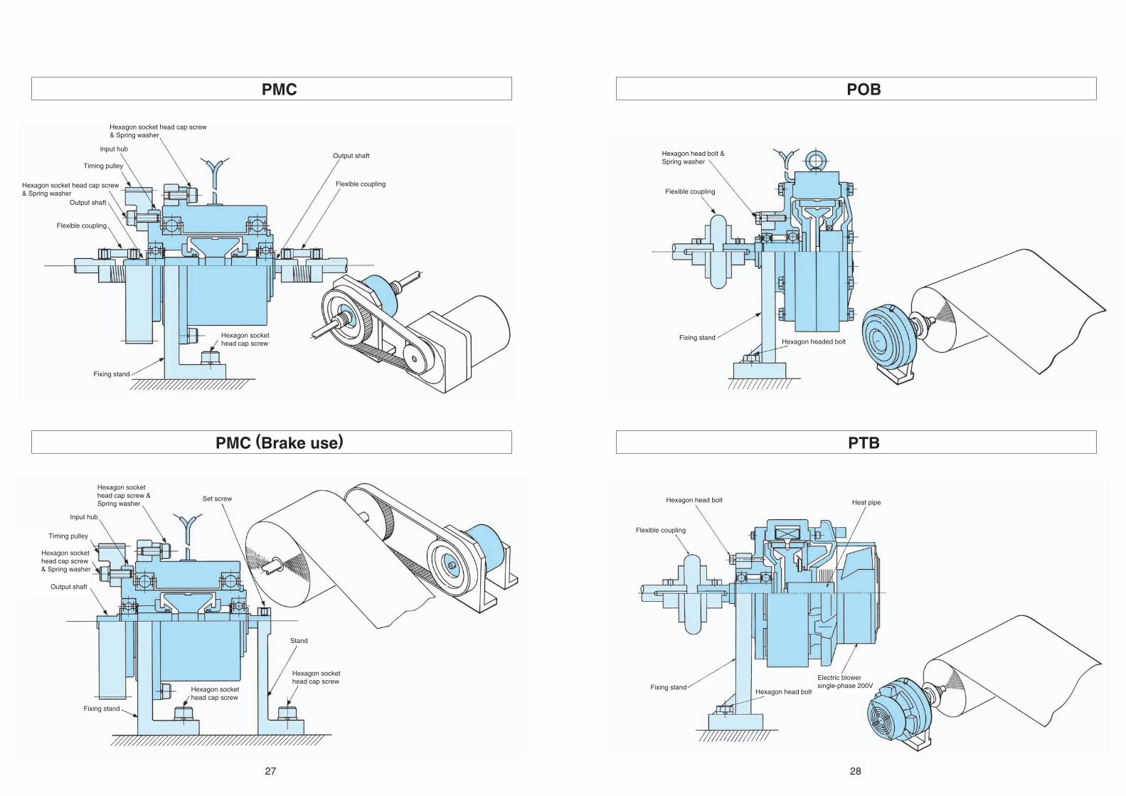
27 28
POB
PTB
PMC
PMC (Brake use)
Hexagon socket head cap screw & Spring washer
Input hub
Set screw
Stand
Hexagon socket head cap screw
Hexagon socket head cap screw
Hexagon head bolt & Spring washer
Flexible coupling
Hexagon headed boltFixing stand
Hexagon head bolt
Hexagon head bolt
Flexible coupling
Heat pipe
Fixing stand
Hexagon socket head cap screw & Spring washer
Hexagon socket head cap screw & Spring washer
Input hub
Timing pulley
Output shaft
Flexible coupling
Output shaft
Flexible coupling
Hexagon socket head cap screw
Fixing stand
Hexagon socket head cap screw & Spring washer
Timing pulley
Output shaft
Electric blowersingle-phase 200V
Fixing stand

29 30
POC-80POC-0.3, 0.6A, 1.2A, 2.5A, 5A, 10, 20, 40Model Static friction torque(Nm) Rated voltage(DC-V) Power consumption at75ϒC(W) Mass(kg)
POC-80 800 24 110 250Model Static friction torque(Nm) Rated voltage(DC-V) Power consumption at75ϒC(W) Mass(kg)
POC-0.6A 6 24 19.2 3.5POC-0.3 3 24 13.3 2.5
POC-1.2A 12 24 20.4 5.5POC-2.5A 25 24 26.8 10POC-5A 50 24 47.3 16.5POC-10 100 24 52.8 35POC-20 200 24 66 58POC-40 400 24 92 100
ModelDiameter direction Shuft direction
AttachmentShuft end
YJD D1 L M X1 Y P.C.D Tap Q QK d b h t
POC-0.3 120 42 147 87 5.8 11 64 M5×10M5×11M6×13M6×13M6×13M10×18M10×18M12×20
23 20 10 4 4 2.5POC-0.6A 134 42 151 86 7 8 64 26 22 12 4 4 2.5POC-1.2A 152 42 178 96 9 8 64 34.5 27 15 5 5 3POC-2.5A 182 55 215 111.5 9 9 78 43 35 20 5 5 3POC-5A 219 74 274 141 8 18 100 57 47 25 7 7 4POC-10 290 100 348 192 7.5 25 140 67 56 30 7 7 4POC-20 335 110 382 216 10.5 25 150 71 60 35 10 8 4.5POC-40 395 130 490 278 22.5 33 200 92 80 45 12 8 4.5
Lead wire 300
Terminal block
Lead wire 300
(Type10,20)
Set screw6-YJ (under Type 20)8-YJ (Type40)
Set screw6-YJ
Terminal block(Type0.3, 40)
Input shaftOutput shaft
Input shaftOutput shaft
Input shaftOutput shaft

31 32
PMC-10, 20A3PHC-0.6, 1.2, 2.5, 5, 10, 20RModel Static friction torque(Nm) Rated voltage(DC-V) Power consumption at75ϒC(W) Mass(kg)
PMC-10A3 1 24 13.5 0.90PMC-20A3 2 24 15 1.34
Model Static friction torque(Nm) Rated voltage(DC-V) Power consumption at75ϒC(W) Mass(kg)PHC-0.6R 6 24 22.5 4.2PHC-1.2R 12 24 23 5.7PHC-2.5R 25 24 30 10PHC-5R 50 24 54 17PHC-10R 100 24 52.8 43PHC-20R 200 24 66 70
ModelDiameter direction Shuft direction Shuft hole
B D D2 D1 L Q R Y1 Y2 Tap
AttachmentYJ1 YJ2
P.C.D Tap d b tPOC-0.6R 89 134 50 50 93 42 25.5 4 4 M4×6 60 M4×6 12 4 13.5POC-1.2R 89 152 45 70 96 46 25 4 4 M4×8 55 M5×6 15 5 17POC-2.5R 140 182 70 70 132 42 45 4 5 M6×9 80 M6×10 25 7 28POC-5R 165 219 87 87 148 68 40 4 4 M8×10 102 M8×10 35 10 38.5
POC-10R 190 290 105 110 183.5 63.5 60 4 6 M8×10 120 M10×13 45 12 48.5POC-20R 220 335 130 130 222 69 75 4 9 M10×13.5
P.C.D608080102140150 150 M10×13.5 55 15 60
ModelDiameter direction Shuft direction Shuft end
C C1 C2 D1 L M M1 N O Hole
AttachmentYJ1 YJ2
P.C.D Tap Q1 Q2 QK
PMC-10A3 76 58 30 58 85 27 15 4 39 4.5 46 M4×6 11 12 10PMC-20A3 92 69 35 69
D25454 116 47 22 4 32
S Y51 651 6 4.5
P.C.D6882 46 M4×6 24 25 20
Lead wire 300
Input hub
Output shaft
Set screw 4-YJ
Lead wire 300
Input hub
Output shaft
Set screw
Set screw6-YJ1
6-YJ2
Set screw

33 34
PMC-40A3 POB-0.3, 0.6A, 1.2A, 2.5A, 5A, 10, 20, 40Model Static friction torque(Nm) Rated voltage(DC-V) Power consumption at75ϒC(W) Mass(kg)
PMC-40A3 4 24 18 2.5Model Static friction torque(Nm) Rated voltage(DC-V) Power consumption at75ϒC(W) Mass(kg)
POB-0.6A 6 24 19.2 3.3 POB-0.3 3 24 13.3 2.5
POB-1.2A 12 24 20.4 4.9 POB-2.5A 25 24 26.8 9 POB-5A 50 24 47.3 15.5 POB-10 100 24 52.8 33 POB-20 200 24 66 48 POB-40 400 24 92 80
ModelDiameter direction Shuft direction
AttachmentShuft end
YJD D1 L M X X1 P.C.D Tap Q QK d b h t
POB-0.3 120 42 105 75 8.6 11 64 M5×10M5×11M6×13M6×13M6×13M10×18M10×18M12×20
23 20 10 4 4 2.5 POB-0.6A 134 42 103.5 71 – 7 64 26 22 12 4 4 2.5 POB-1.2A 152 42 120 79 – 9 64 34.5 27 15 5 5 3 POB-2.5A 182 55 145.5 94 – 9 78 43 35 20 5 5 3 POB-5A 219 74 181 114.5 – 8 100 57 47 25 7 7 4 POB-10 290 100 233.5 155.5 7.5 7.5 140 67 56 30 7 7 4 POB-20 335 110 263.5 180.5 9.5 10.5 150 71 60 35 10 8 4.5 POB-40 395 130 330 224 16.1 22.5
Y1188918252533 200 92 80 45 12 8 4.5
Lead wire 300
Lead wire 300
Input hub
Output shaft
Lead wire 300
(Type10,20)
Set screw
6-YJ (under Type 20)8-YJ (Type40)
Set screw6-YJ
Terminal block(Type0.3, 40)

35 36
PHB-0.6, 1.2, 2.5, 5, 10, 20Model Static friction torque(Nm) Rated voltage(DC-V) Power consumption at75ϒC(W) Mass(kg)
PHB-0.6 6 24 22.5 4.0PHB-1.2 12 24 23 5.0PHB-2.5 25 24 30 9.0PHB-5 50 24 54 15
PHB-10 100 24 52.8 38PHB-20 200 24 66 48
POB-80Model Static friction torque(Nm) Rated voltage(DC-V) Power consumption at75ϒC(W) Mass(kg)
POB-80 800 24 110 260
ModelDiameter direction Shuft direction
AttachmentShuft hole
KB B1 D D1 L R Q S Y X K KJ d b t
PHB-0.6 90 45 134 70 82.3 59.5 18 2 3 4.8 80 M5×12 12 4 13.5PHB-1.2 102 45 152 75 85 59 21 5 4 5.5 88 M6×10 15 5 17PHB-2.5 129 70 182 102 116 87 19.5 5 4 5.5 115 M6×12 25 7 28PHB-5 157 85 219 128 133 95.5 35.5 6.5 5 5.5 140 M6×15 32 10 35.5
PHB-10 210 100 290 160 160 114 28.5 5 5 7.5 180 M8×20 42 12 45.5PHB-20 244 120 335 190 188 130 50 5 5 11 220 M10×20 55 15 60
Lead wire 300
Set screw 6-YJ
Terminal block

37 38
PTB-2.5, 5, 10, 20, 40BL3PRB-1.2, 2.5, 5, 10, 20HModel Static friction torque(Nm) Rated voltage(DC-V) Power consumption at75ϒC(W) Mass(kg)
PTB-2.5BL3 25 24 30 11PTB-5BL3 50 24 54 17PTB-10BL3 100 24 52.8 34.5PTB-20BL3 200 24 66 51.5PTB-40BL3 400 24 92 85
Model Static friction torque(Nm) Rated voltage(DC-V) Power consumption at75ϒC(W) Mass(kg)PRB-1.2H 12 24 15 4PRB-2.5H 25 24 18.5 5.2PRB-5H 50 24 24.5 10
PRB-10H 100 24 32 20PRB-20H 200 24 36 36
ModelDiameter direction Shuft direction
AttachmentShuft hole
DJC D L M O P P.C.D Tap d b t
M5×10M5×10M6×12M6×12M8×12
PRB-1.2H 109 136 63 42 5.5 53 125 15 5 17 PRB-2.5H 124 160 73 47 6.5 60 148 20 5 22 PRB-5H 149 195 84.5 57 5 67 181 30 7 33 PRB-10H 188 250 104 68 5 78 233 30 7 33 PRB-20H 234 305
D1136160195250305 128.5 80 7.5 95 282 40 10 43.5
Y7
7.58
8.512
ModelDiameter direction Shuft direction
AttachmentShuft end
YJD D1 I L M N P.C.D Tap Q QK d b h t
M6×13M6×13M10×18M10×18M12×20
PTB-2.5BL3 182 55 120 221.5 169.5 43 78 43 38 20 5 5 3PTB-5BL3 219 74 ø150 274.5 208 61.5 100 57 47 25 7 7 4PTB-10BL3 290 100 ø150 335 257 61.5 140 67 56 30 7 7 4PTB-20BL3 335 110 ø150 352.5 269.5 61.5 150 71 60 35 10 8 4.5PTB-40BL3 395 130 ø268 482 376 68
Y1523252533 200 92 80 45 12 8 4.5
Set screw
Set screw
Set screw
6-DJ (under type 5)8-DJ (over type 10)
Lead wire 300
Terminal block
Terminal block
Electric blowersingle-phase 200V
Electric blowersingle-phase 200V