Embed Size (px)
DESCRIPTION
rules
Citation preview

Rules for the Classification ofMilitary Ships
PART F - Additional Class Notations
Chapters 1 – 2 – 3 – 4 – 5 – 6 – 7 – 8 – 9 – 10
NR 483.9 DTM R00 E June 2003
17 bis, Place des Reflets – La Défense 2 – 92400 CourbevoiePostal Address : 92077 Paris La Défense Cedex
Tel. 33 (0) 1 42 91 52 91 – Fax. 33 (0) 1 42 91 53 20Email : [email protected]
Web : http://www.veristar.com

BV Mod. Ad. WE 545i - 05/2002
MARINE DIVISION – GENERAL CONDITIONSARTICLE 11.1. - BUREAU VERITAS is a Society the purpose of whose Marine Division (the“Society”) is the classification (« Classification ») of any ship or vessel or structure of anytype or part of it or system therein collectively hereinafter referred to as a “Unit” whetherlinked to shore, river bed or sea bed or not, whether operated or located at sea or ininland waters or partly on land, including submarines, hovercrafts, drilling rigs, offshoreinstallations of any type and of any purpose, their related and ancillary equipment, subseaor not, such as well head and pipelines, mooring legs and mooring points or otherwise asdecided by the Society.The Society:• prepares and publishes Rules for classification, Guidance Notes and other
documents (« Rules »);• issues Certificates, Attestations and Reports following its interventions
(« Certificates »);• publishes Registers.1.2. - The Society also participates in the application of National and InternationalRegulations or Standards, in particular by delegation from different Governments. Thoseactivities are hereafter collectively referred to as « Certification ».1.3. - The Society can also provide services related to Classification and Certificationsuch as ship and company safety management certification; training activities; allactivities and duties incidental thereto such as documentation on any supporting means,software, instrumentation, measurements, tests and trials on board.1.4. - The interventions mentioned in 1.1., 1.2. and 1.3. are referred to as « Services ».The party and/or its representative requesting the services is hereinafter referred to as the« Client ». The Services are prepared and carried out on the assumption that theClients are aware of the International Maritime and/or Offshore Industry (the“Industry”) practices.1.5. - The Society is neither and may not be considered as an Underwriter, Broker inship’s sale or chartering, Expert in Unit’s valuation, Consulting Engineer, Controller, NavalArchitect, Manufacturer, Shipbuilder, Repair yard, Charterer or Shipowner who are notrelieved of any of their expressed or implied obligations by the interventions of theSociety.
ARTICLE 22.1. - Classification is the appraisement given by the Society for its Client, at a certaindate, following surveys by its Surveyors along the lines specified in Articles 3 and 4hereafter on the level of compliance of a Unit to its Rules or part of them. Thisappraisement is represented by a class entered on the Certificates and periodicallytranscribed in the Society’s Register.2.2. - Certification is carried out by the Society along the same lines as set out in Articles3 and 4 hereafter and with reference to the applicable National and InternationalRegulations or Standards.2.3. - It is incumbent upon the Client to maintain the condition of the Unit aftersurveys, to present the Unit for surveys and to inform the Society without delay ofcircumstances which may affect the given appraisement or cause to modify itsscope. 2.4. - The Client is to give to the Society all access and information necessary for theperformance of the requested Services.
ARTICLE 33.1. - The Rules, procedures and instructions of the Society take into account at thedate of their preparation the state of currently available and proven technicalknowledge of the Industry. They are not a code of construction neither a guide formaintenance or a safety handbook.Committees consisting of personalities from the Industry contribute to the development ofthose documents.3.2. - The Society only is qualified to apply its Rules and to interpret them. Anyreference to them is void unless it involves the Society’s intervention.3.3. - The Services of the Society are carried out by professional Surveyors according tothe Code of Ethics of the Members of the International Association of ClassificationSocieties (IACS).3.4. - The operations of the Society in providing its Services make use of randominspections and are absolutely exclusive of any monitoring and thoroughverification.
ARTICLE 44.1. - The Society, acting by reference to its Rules:• reviews the construction arrangements of the Units as shown on the documents
presented by the Client;• conducts surveys at the place of their construction;• classes Units and enters their class in its Register;• surveys periodically the Units in service to note that the requirements for the
maintenance of class are met.The Client is to inform the Society without delay of circumstances which may causethe date or the extent of the surveys to be changed.
ARTICLE 55.1. - The Society acts as a provider of services. This cannot be construed as anobligation bearing on the Society to obtain a result or in a warranty.5.2. - The certificates issued by the Society pursuant to 5.1. here above are astatement on the level of compliance of the Unit to its Rules or to the documents ofreference for the Services provided for.In particular, the Society does not engage in any work relating to the design,building, production or repair checks, neither in the operation of the Units or in theirtrade, neither in any advisory services, and cannot be held liable on those accounts.Its certificates cannot be construed as an implied or express warranty of safety,fitness for the purpose, seaworthiness of the Unit or of its value for sale, insuranceor chartering.5.3. - The Society does not declare the acceptance or commissioning of a Unit, thatbeing the exclusive responsibility of its owner.
5.4. - The Services of the Society cannot create any obligation bearing on the Society orconstitute any warranty of proper operation, beyond any representation set forth in theRules, of any Unit, equipment or machinery, computer software of any sort or othercomparable concepts that has been subject to any survey by the Society.
ARTICLE 66.1. - The Society accepts no responsibility for the use of information related to itsServices which was not provided for the purpose by the Society or with its assistance.6.2. - If the Services of the Society cause to the Client a damage which is proved tobe the direct and reasonably foreseeable consequence of an error or omission ofthe Society, its liability towards the Client is limited to ten times the amount of feepaid for the Service having caused the damage. This limit is subject to a minimumof eight thousand (8,000) Euro, and to a maximum which is the greater of eighthundred thousand (800,000) Euro and one and a half times the above mentionedfee.The Society bears no liability for indirect or consequential loss such as e.g. loss ofrevenue, loss of profit, loss of production, loss relative to other contracts andindemnities for termination of other agreements.6.3. - All claims are to be presented to the Society in writing and on pain ofdebarment by right, within three months of the date the Services were supplied or ofthe date the events which are taken advantage of were first known.
ARTICLE 77.1. - Requests for Services are to be in writing.7.2. - Either the Client or the Society can terminate as of right the requestedServices after giving the other party thirty days' written notice, for convenience, andwithout prejudice to the provisions in Article 8 hereunder.7.3. - The class granted to the concerned Units and the previously issued certificatesremain valid until the date of effect of the notice issued according to 7.2. hereabovesubject to compliance with 2.3. hereabove and Article 8 hereunder.
ARTICLE 88.1. - The Services of the Society, whether completed or not, involve the payment of feeupon receipt of the invoice and the reimbursement of the expenses incurred.8.2. Overdue amounts are increased as of right by penalties at a monthly rate of oneand a half percent.8.3. - The class of a Unit may be suspended in the event of non-payment of fee aftera first unfruitful notification to pay.ARTICLE 99.1. - The documents and data provided to or prepared by the Society for its Services,and the information available to the Society, are treated as confidential. However:• Clients have access to the data they have provided to the Society and to the
classification file consisting of reports and certificates which have been prepared forthem;
• copy of the documents made available for the classification of the Unit and ofavailable survey reports can be handed over to another Classification SocietyMember of the International Association of Classification Societies (IACS) in case ofthe Unit’s transfer of class;
• the data relative to the evolution of the Register, to the class suspension and to thesurvey status of the Units are passed on to IACS according to the associationworking rules;
• technical records and history related to specific class notations may be transferred tothe new owner in case of change of ownership;
• the certificates, documents and information relative to the Units classed with theSociety are passed on upon order of the concerned governmental authorities or of aCourt having jurisdiction.
The documents and data are subject to a file management plan.
ARTICLE 1010.1. - Any delay or shortcoming in the performance of its Services by the Society arisingfrom an event not reasonably foreseeable by or beyond the control of the Society shall bedeemed not to be a breach of contract.
ARTICLE 1111.1. - The Society may designate another Surveyor at the request of the Client in case ofdiverging opinions during surveys.11.2. - Disagreements of a technical nature between the Client and the Society can besubmitted by the Society to the advice of its Classification Committee.
ARTICLE 1212.1. - Disputes over the Services carried out by delegation of Governments are assessedwithin the framework of the applicable agreements with the States, internationalConventions and national rules.12.2. - Disputes arising out of the payment of the Society’s invoices by the Client aresubmitted to the Court of Nanterre, France.12.3. - Other disputes over the present General Conditions or over the Services ofthe Society are exclusively submitted to arbitration, by three arbitrators, in Londonaccording to the London arbitration procedural rules in force. English law applies.
ARTICLE 1313.1. - These General Conditions constitute the sole contractual obligations bindingtogether the Society and the Client, to the exclusion of all other representation,statements, terms, conditions whether express or implied. They may be varied inwriting by mutual agreement.13.2. - The invalidity of one or more stipulations of the present General Conditions doesnot affect the validity of the remaining provisions.13.3. - The definitions herein take precedence over any definitions serving the samepurpose which may appear in other documents issued by the Society.

RULES FOR
THE CLASSIFICATION OF MILITARY SHIPS
Part FAdditional Class Notations
Chapters 1 2 3 4 5 6 7 8 9 10
Chapter 1 VeriSTAR SYSTEM (STAR)
Chapter 2 AVAILABILITY OF MACHINERY (AVM)
Chapter 3 AUTOMATION SYSTEMS (AUT)
Chapter 4 INTEGRATED SHIP SYSTEMS (SYS)
Chapter 5 MONITORING EQUIPMENT (MON)
Chapter 6 COMFORT ON BOARD (COMF)
Chapter 7 REFRIGERATING INSTALLATION (REEFER)
Chapter 8 ICE CLASS (ICE)
Chapter 9 MILITARY STRENGTHENING
Chapter 10 OTHER ADDITIONAL CLASS NOTATIONS
June 2003

Unless otherwise specified, these rules apply to ships for which contracts aresigned after July 1st, 2003. The Society may refer to the contents hereofbefore July 1st, 2003, as and when deemed necessary or appropriate.
2 BVmili June 2003

CHAPTER 1VERISTAR SYSTEM (STAR)
Section 1 Star-Hull
1 General 27
1.1 Principles1.2 Conditions for the assignment and maintenance of the notation1.3 Ship database
2 Documentation to be submitted 28
2.1 Plans and documents to be submitted2.2 Hot spot map2.3 Inspection and Maintenance Plan (IMP)
3 Inspection and Maintenance Plan (IMP) 29
3.1 Minimum requirements3.2 General scope of IMP3.3 Periodicity of inspections3.4 Extent of inspections3.5 Inspection reports3.6 Changes to Inspection and Maintenance Plan
4 Acceptance criteria 32
4.1 Coating assessment4.2 Sacrificial anode condition4.3 Thickness measurements4.4 Pitting4.5 Fractures
5 Maintenance of the notation 33
5.1 Annual audit at the Owner’s offices5.2 Annual shipboard audit5.3 Class renewal survey5.4 Suspension and withdrawal of the notation
Section 2 VeriSTAR-HULL
1 General 37
1.1 Application1.2 Scope
2 Assignment of the notation 37
2.1 New buildings2.2 Ships in service
3 Maintenance of the notation 38
3.1 Ship database3.2 Class renewal survey
June 2003 BVmili 3

Section 3 Star-Mach
1 General 40
1.1 Application1.2 Definitions1.3 Scope
2 Assignment of the notation 40
2.1 Documentation to be submitted2.2 Maintenance Management System2.3 Interventions of the Society
3 Maintenance of the notation 41
3.1 General3.2 Chief Engineer authorization3.3 Initial intervention3.4 Periodical audits and interventions3.5 Occasional Audits3.6 Amendments to the Maintenance Plan
4 Termination 42
4.1 Conditions
Appendix 1 Acceptance Criteria for Isolated Areas of Items
1 General 43
1.1 Application
Appendix 2 Acceptance Criteria for Isolated Items
1 Partial safety factors 46
1.1 General1.2 Partial safety factors based on the increased knowledge of the structure
2 Acceptance criteria for plating 46
2.1 Application2.2 Renewal thicknesses
3 Acceptance criteria for ordinary stiffeners 48
3.1 Application3.2 Renewal scantlings
4 Acceptance criteria for primary supporting members 49
4.1 Application4.2 Work ratios4.3 Renewal scantlings
Appendix 3 Acceptance Criteria for Zones
1 General 52
1.1 Application
4 BVmili June 2003

Appendix 4 Owner’s Hull Inspection Reports
1 General 53
1.1
2 Report for inspection of spaces 53
2.1 General2.2 Identification data2.3 Summary of findings and repairs2.4 Details of findings and repairs2.5 Attached documentation
3 Report for inspection of equipment 55
3.1 General3.2 Identification data3.3 Detailed report3.4 Attached documentation
June 2003 BVmili 5
CHAPTER 2AVAILABILITY OF MACHINERY (AVM)
Section 1 Alternative Propulsion System (AVM-APS)
1 General 59
1.1 Application1.2 Coverage of AVM-APS notation1.3 Documentation to be submitted
2 Special arrangements 60
2.1 Propulsion system2.2 Systems for cooling, lubrication, fuel supply, air starting, monitoring and control2.3 Electrical installations2.4 Summary
3 Tests on board 62
3.1 Running tests3.2 Sea trials
Section 2 Duplicated Propulsion System (AVM-DPS)
1 General 63
1.1 Application1.2 Coverage of AVM-DPS notation1.3 Documentation to be submitted
2 Special arrangements 64
2.1 Systems for cooling, lubrication, fuel supply, air starting, monitoring and control2.2 Rudders and steering gears2.3 Electrical installations2.4 Automation
3 Tests on board 65
3.1 Running tests3.2 Sea trials
Section 3 Independent Propulsion System (AVM-IPS)
1 General 66
1.1 Application1.2 Coverage of AVM-IPS notation1.3 Documentation to be submitted
2 Special arrangements 67
2.1 Systems for cooling, lubrication, fuel supply, air starting, monitoring and control2.2 Rudders and steering gears2.3 Electrical installations2.4 Automation
6 BVmili June 2003

3 Tests on board 68
3.1 Running tests3.2 Sea trials
Appendix 1 Procedures for Failure Modes and Effect Analysis
1 General 69
1.1 Introduction1.2 Objectives1.3 Sister ships1.4 FMEA basics1.5 FMEA analysis
2 FMEA performance 70
2.1 Procedures2.2 System definition2.3 Development of system block diagram2.4 Identification of failure modes, causes and effects2.5 Failure effects2.6 Failure detection2.7 Corrective measures2.8 Use of probability concept2.9 Documentation
3 Tests and reporting 73
3.1 Test program3.2 Reporting
4 Probabilistic concept 73
4.1 General4.2 Occurences4.3 Probability of occurences4.4 Effects4.5 Safety level4.6 Numerical values
June 2003 BVmili 7

CHAPTER 3AUTOMATION SYSTEMS (AUT)
Section 1 Unattended Machinery Spaces (AUT-UMS)
1 General 79
1.1 Application1.2 Communication system
2 Documentation 79
2.1 Documents to be submitted
3 Fire and flooding precautions 79
3.1 Fire prevention3.2 Fire detection3.3 Fire fighting3.4 Protection against flooding
4 Control of machinery 80
4.1 General4.2 Diesel propulsion plants4.3 Gas turbine propulsion plants4.4 Electrical propulsion plant4.5 Shafting, clutches, CPP, gears4.6 Auxiliary system4.7 Control of electrical installation
5 Alarm system 93
5.1 General5.2 Alarm system design5.3 Machinery alarm system5.4 Alarm system on navigating bridge
6 Safety systems 93
6.1 General
7 Testing 94
7.1 General
Section 2 Centralised Control Station (AUT-CCS)
1 General 95
1.1 Application1.2 Communication system
2 Documentation 95
2.1 Documents to be submitted
3 Fire and flooding precautions 95
3.1 General
8 BVmili June 2003

4 Control of machinery 95
4.1 Propulsion plant operation4.2 Control position location
5 Alarm system 96
5.1 General
6 Safety system 96
6.1 General
7 Testing 96
7.1 Tests after completion7.2 Sea trials
Section 3 Automated Operation in Port (AUT-PORT)
1 General 97
1.1 Application1.2 Communication system
2 Documentation 97
2.1 Documents to be submitted
3 Fire and flooding precautions 97
3.1 general
4 Control of machinery 97
4.1 Plant operation
5 Alarm system 97
5.1 General
6 Testing 97
6.1 Tests after completion
Section 4 Integrated Machinery Spaces (AUT-IMS)
1 General 98
1.1 Application
2 Documentation 98
2.1 Documents to be submitted
3 Fire and flooding precautions 98
3.1 Fire prevention3.2 Fire detection3.3 Fire fighting3.4 Protection against flooding
4 Design requirements 99
4.1 General4.2 Integrated computer based systems
June 2003 BVmili 9

5 Construction requirements 100
5.1 Electrical and electronic construction requirements5.2 Pneumatic construction requirements5.3 Hydraulic construction requirements
6 Control of machinery 100
6.1 General6.2 Diesel propulsion plants6.3 Gas turbine propulsion plant6.4 Electric propulsion plant6.5 Shafting, clutches, CPP, gears6.6 Auxiliary systems6.7 Control of electrical installation
7 Testing 105
7.1 Additional testing7.2 Maintenance equipment
10 BVmili June 2003

CHAPTER 4INTEGRATED SHIP SYSTEMS (SYS)
Section 1 Centralised Navigation Equipment (SYS-NEQ)
1 General 109
1.1 Application1.2 Operational Assumptions1.3 Regulations, guidelines, standards1.4 Definitions
2 Documentation 110
2.1 Documents to be submitted
3 Bridge layout 110
3.1 General
4 Bridge instrumentation and controls 111
4.1 General4.2 Safety of navigation: collision-grounding4.3 Position fixing4.4 Controls - Communication
5 Design and reliability 112
5.1 General5.2 Power supply5.3 Environmental conditions
6 Prevention of accidents caused by operator’s unfitness 112
6.1 Bridge safety system6.2 Field of vision6.3 Alarm/warning transfer system - Communications6.4 Bridge layout
7 Ergonomical recommendations 113
7.1 Lighting7.2 Noise level7.3 Vibration level7.4 Wheelhouse space heating/cooling7.5 Navigator’s safety
8 Testing 114
8.1 Tests
Section 2 Integrated Bridge Systems (SYS-IBS)
1 General 115
1.1 Application1.2 Reference Regulations1.3 Definitions1.4 Abbreviations
June 2003 BVmili 11
2 Documentation 116
2.1 Documents to be submitted
3 General requirements 116
3.1 General3.2 Integration3.3 Data exchange3.4 Failure analysis3.5 Quality assurance
4 Operational requirements 118
4.1 Human factors4.2 Functionality4.3 Training
5 Technical requirements 119
5.1 Sensors5.2 Alarm management5.3 Human factors5.4 Power interruptions and shutdown5.5 Power supply
6 Testing 120
6.1 Introduction6.2 General requirements6.3 Operational requirements6.4 Technical requirements
Section 3 Communication System (SYS-COM)
1 General 124
1.1 Application
2 Documentation 124
2.1 Documents to be submitted
3 Design requirements 124
3.1 General3.2 Content of data transmitted3.3 Transmission safety
4 Construction requirements 125
4.1 General
5 Testing 125
5.1 Design validation5.2 Product type approval5.3 Shipboard testing
12 BVmili June 2003

CHAPTER 5MONITORING EQUIPMENT (MON)
Section 1 Hull Stress and Motion Monitoring (MON-HULL)
1 General 129
1.1 Application1.2 Documentation1.3 Data limits, warning levels
2 Hull monitoring system 129
2.1 Main functions2.2 Sensors2.3 Specifications2.4 Data processing2.5 Visual display2.6 Alarms2.7 Data storage2.8 Exploitation and checking of stored data2.9 Power supply unit2.10 Calibration2.11 Checking facility
Section 2 Shaft Monitoring (MON-SHAFT)
1 General 132
1.1 Applicability of MON-SHAFT notation
2 Requirements for the issuance of the notation 132
2.1 Arrangement2.2 Lubricating oil analysis
June 2003 BVmili 13

CHAPTER 6COMFORT ON BOARD (COMF)
Section 1 General Requirements
1 General 135
1.1 Application1.2 Basic principles1.3 References
2 Conditions of attribution 135
2.1 Measurements2.2 Determination of comfort rating number2.3 Measuring areas
3 Testing conditions 136
3.1 General3.2 Test conditions
Section 2 Additional Requirements for Notation COMF-NOISE
1 General 138
1.1 Application
2 Measurement procedure 138
2.1 Instrumentation2.2 Data processing - Analysis2.3 Measuring conditions2.4 Measuring positions
3 Noise levels 138
3.1 Noise levels in standard spaces3.2 Additional measurements and checking
Section 3 Additional Requirements for Notation COMF-VIB
1 General 140
1.1 Application
2 Measurement procedure 140
2.1 Instrumentation2.2 Data processing, analysis, presentation of results2.3 Mesuring conditions2.4 Mesuring positions
3 Vibration levels 141
3.1 Vibration limits3.2 Determination of the “equivalent vibration level”
14 BVmili June 2003

Appendix 1 International Standards
1 Vibrations 142
1.1 Limit curves of ISO 6954
2 Noise 142
2.1 Noise limits of IMO
June 2003 BVmili 15

CHAPTER 7REFRIGERATING INSTALLATION (REEFER)
Section 1 General Requirements
1 General 145
1.1 Application1.2 Temperature conditions1.3 Definitions
2 Design criteria 145
2.1 Reference conditions
3 Documentation 145
3.1 Refrigerating installations
4 General technical requirements 146
4.1 Refrigeration of chambers4.2 Refrigerating unit4.3 Defrosting4.4 Prime movers and sources of power4.5 Pumps4.6 Sea connections 4.7 Refrigerating unit spaces
5 Refrigerated chambers 147
5.1 Construction of refrigerated chambers 5.2 Penetrations5.3 Access to refrigerated spaces5.4 Insulation of refrigerated chambers 5.5 Protection of insulation5.6 Miscellaneous requirements 5.7 Installation of the insulation5.8 Drainage of refrigerated spaces
6 Refrigerants 149
6.1 General6.2 Rated working pressures
7 Refrigerating machinery and equipment 149
7.1 Prime movers7.2 Common requirements for compressors7.3 Reciprocating compressors7.4 Pressure vessels7.5 General requirements for piping7.6 Accessories7.7 Refrigerating plant overpressure protection
8 Specific requirements for direct cooling systems 151
8.1 Specific requirements for air cooling systems and distribution and renewal of air in refrigerated chambers
16 BVmili June 2003

9 Instrumentation, alarm, monitoring 151
9.1 General9.2 Instrumentation, alarm and monitoring arrangement
10 Material tests, inspection and testing, certification 151
10.1 Material testing10.2 Shop tests10.3 Pressure tests at the workshop10.4 Thermometers and manometers10.5 Shipboard tests10.6 Defrosting system
June 2003 BVmili 17

CHAPTER 8ICE CLASS (ICE)
Section 1 General
1 General 157
1.1 Application1.2 Owner’s responsibility
2 Ice class draughts and ice thickness 157
2.1 Definitions2.2 Draught limitations2.3 Ice thickness
3 Output of propulsion machinery 158
3.1 Required engine output for classes IB and IC3.2 Required engine output for classes IAS and IA
Section 2 Hull and Stability
1 General 160
1.1 Application1.2 Regions1.3 Ice strengthened area
2 Structure design principles 161
2.1 General framing arrangement2.2 Transverse framing arrangement2.3 Bilge keels
3 Design loads 162
3.1 General3.2 Ice loads
4 Hull scantlings 163
4.1 Plating4.2 Ordinary stiffeners4.3 Primary supporting members
5 Other structures 166
5.1 Application5.2 Fore part5.3 Aft part5.4 Deck strips and hatch covers5.5 Sidescuttles and freeing ports
6 Hull outfitting 167
6.1 Rudders and steering arrangements6.2 Bulwarks
18 BVmili June 2003

Section 3 Machinery
1 Propulsion 168
1.1 Propulsion machinery performance1.2 Ice torque1.3 Starting arrangements for propulsion machinery1.4 Propellers1.5 Shafting1.6 Reverse and reduction gearing
2 Miscellaneous requirements 170
2.1 Sea inlets and cooling water systems of machinery2.2 Steering gear2.3 Fire pumps
June 2003 BVmili 19

CHAPTER 9MILITARY STRENGTHENING
Section 1 Helicopters
1 General 173
1.1 Application1.2 General arrangement
2 Seakeeping 173
2.1 Principles2.2 Verification
3 Structural strength 173
3.1 Helicopter decks3.2 Helicopter storage
4 Fire safety 173
4.1 Helicopter installations4.2 Helicopter decks4.3 Helicopter storage space
Section 2 Ammunition
1 Application 174
1.1 General1.2 Ammunition classification
2 General arrangement 174
2.1 General2.2 Ammunition holds2.3 Ammunition cupboards2.4 Ammunition transfer routes
Section 3 IMPSUR
1 General 177
1.1 Application1.2 Requirements
2 Stability 177
2.1 General2.2 Extent of damage
3 Hull structure 177
3.1 General arrangement3.2 Materials3.3 Structural details3.4 Resistance to underwater explosions
20 BVmili June 2003

4 Machinery, piping and electricity 179
4.1 Critical components and equipment4.2 Requirements for machinery and piping4.3 Requirements for electricity4.4 Emergency equipment4.5 Resistance to explosions
5 Fire safety 182
5.1 General
June 2003 BVmili 21

CHAPTER 10OTHER ADDITIONAL CLASS NOTATIONS
Section 1 Strengthened Bottom (STRENGTHBOTTOM)
1 General 185
1.1 Application
2 Double bottom 185
2.1 Ships with L < 90 m and longitudinally framed double bottom2.2 Ships with L < 90 m and transversely framed double bottom2.3 Ships with L ≥ 90 m
3 Single bottom 185
3.1 Scantlings
Section 2 In-Water Survey Arrangements(INWATERSURVEY)
1 General 186
1.1 Application1.2 Documentation to be submitted
2 Structure design principles 186
2.1
Section 3 Container Lashing Equipment (LASHING)
1 General 187
1.1 Application1.2 Documents to be kept on board1.3 Materials
2 Arrangement of containers 187
2.1 General2.2 Stowage in holds using removable cell guides2.3 Stowage under deck without cell guides2.4 Stowage on exposed deck 2.5 Uniform line load stowage on deck or hatch covers
3 Procedure for the assignment of the notation 189
3.1 Approval of the mobile lashing equipment3.2 Type tests3.3 Inspection at works of the mobile lashing equipment3.4 Reception on board of the mobile lashing equipment
22 BVmili June 2003

4 Forces applied to containers 191
4.1 General4.2 Definitions4.3 Still water and inertial forces4.4 Wind forces4.5 Forces imposed by lashing and securing arrangements4.6 Sea pressure
5 Determination of loads in lashing equipment and in container frames 193
5.1 Calculation hypothesis5.2 Distribution of forces5.3 Containers only secured by locking devices5.4 Containers secured by means of lashings or buttresses5.5 Stiffnesses
6 Strength criteria 195
6.1 Permissible loads on containers 6.2 Permissible loads induced by lashing on container corners 6.3 Permissible loads on lashing equipment 6.4 Permissible stresses on cell guides
Section 4 Towing
1 Emergency towing arrangements 196
1.1 Definitions1.2 Application1.3 Documentation1.4 General1.5 Emergency towing arrangement approval1.6 Safe working load (SWL) of towing pennants, chafing gears, fairleads and
strongpoints1.7 Towing pennant1.8 Chafing gear1.9 Fairleads1.10 Strongpoint1.11 Hull structures in way of fairleads or strongpoints1.12 Rapid deployment of towing arrangement1.13 Type approval
June 2003 BVmili 23

24 BVmili June 2003

Part FAdditional Class Notations
Chapter 1
VeriSTAR SYSTEM (STAR)
SECTION 1 STAR-HULL
SECTION 2 VERISTAR-HULL
SECTION 3 STAR-MACH
APPENDIX 1 ACCEPTANCE CRITERIA FOR ISOLATED AREAS OF ITEMS
APPENDIX 2 ACCEPTANCE CRITERIA FOR ISOLATED ITEMS
APPENDIX 3 ACCEPTANCE CRITERIA FOR ZONES
APPENDIX 4 OWNER’S HULL INSPECTION REPORTS
June 2003 BVmili 25

26 BVmili June 2003

Pt F, Ch 1, Sec 1
SECTION 1 STAR-HULL
1 General
1.1 Principles
1.1.1 Application
The additional class notation STAR-HULL is assigned, inaccordance with Pt A, Ch 1, Sec 2, [5.3.3], to ships comply-ing with the requirements of this Section.
1.1.2 Scope
The additional class notation STAR-HULL is assigned to aship in order to reflect the fact that a procedure includingperiodical and corrective maintenance, as well as periodi-cal and occasional inspections of hull structures and equip-ment, (hereafter referred to as the Inspection andMaintenance Plan) are dealt with on board by the crew andat the Owner’s offices according to approved procedures.
The assignment of the notation implies that a structural tridi-mensional analysis has been performed for the hull struc-tures, as defined in Pt B, Ch 7, App 1 or Pt B, Ch 7, App 2 orPt B, Ch 7, App 3, as applicable.
The implementation of the Inspection and MaintenancePlan is surveyed by the Society through:
• periodical audits carried out at the Owner’s offices andon board
• examination of the data recorded by the Owner andmade available to the Society through an electronic shipdatabase suitable for consultation and analysis
• periodical check of the hull structure, normally at theclass renewal survey, against defined acceptance crite-ria and based on:
- the collected data from actual implementation of theInspection and Maintenance Plan
- the results of the inspections, thickness measure-ments and other checks carried out during the classrenewal survey (see [5]).
1.1.3 Safety management system
The Inspection and Maintenance Plan required under thescope of the STAR-HULL notation may form part of theSafety Management System to be certified in compliancewith the ISM Code.
1.2 Conditions for the assignment andmaintenance of the notation
1.2.1 Assignment of the notation
The procedure for the assignment of the STAR-HULL nota-tion is the following:
• a request for the notation is to be sent to the Society:
- signed by the party applying for the classification, inthe case of new ships
- signed by the Owner, in the case of existing ships
• the following documents are to be submitted to theSociety by the Interested Party:
- plans and documents necessary to carry out thestructural analysis, and information on coatings andon cathodic protection (see [2.1])
- the hot spot map of the structure (see [2.2])
- the Inspection and Maintenance Plan to be imple-mented by the Owner (see [2.3])
- information concerning the ship database and rele-vant electronic support to be implemented by theOwner (see [1.3.1])
• the Society reviews and approves the Inspection andMaintenance Plan, taking into account the results of thestructural analysis, as well as the information concern-ing the ship database
• the Society carries out an initial shipboard audit to ver-ify the compliance of the procedures on board withrespect to the submitted documentation.
1.2.2 Maintenance of the notationThe maintenance of the STAR-HULL notation is based onthe following surveys and checks, whose scope and perio-dicity are specified in [5], to be carried out by the Society:
• annual audits at the Owner’s offices (see [5.1])
• annual shipboard audits (see [5.2])• class renewal surveys (see [5.3]).
1.3 Ship database
1.3.1 The ship database, to be available on board and atthe Owner’s offices, using an electronic support suitable forconsultation and analysis, is to provide at least the follow-ing information:
• the hot spot map, as indicated in [2.2]
• the documents required for the Inspection and Mainte-nance Plan, as indicated in [2.3], and the correspondingreports during the ship operation, as indicated in [3.5].
The ship database is to include a backup system in order forthe data to be readily restored, if needed.
1.3.2 The ship database is to be:
• updated by the Owner each time new inspection andmaintenance data from the ship are available
• kept by the Owner.
Access to the databases is to be logged, controlled andsecured.
June 2003 BVmili 27

Pt F, Ch 1, Sec 1
1.3.3 The ship database is to be made available to the Soci-ety.
This ship database is to be transmitted to the Society at leastevery six months. It may be agreed between the Owner andthe Society that the required data are automatically down-loaded into the Society’s ship database after they are col-lected.
2 Documentation to be submitted
2.1 Plans and documents to be submitted
2.1.1 Structural analysis
The plans and documents necessary to support and/or per-form the structural analysis covering hull structures are:
• those submitted for class as listed in Pt B, Ch 1, Sec 3,for new ships
• those listed in Tab 1, for existing ships. However,depending on the service and specific features of theship, the Society reserves the right to request additionalor different plans and documents from those in Tab 1.
Table 1 : Existing ships - Plans and documentsto be submitted to perform the structural analysis
2.1.2 Coatings
The following information on coatings is to be submitted:
• list of all structural items which are effectively coated
• characteristics of the coating system.
2.1.3 Cathodic protection
The following information on sacrificial anodes is to be sub-mitted:
• localisation of anodes in spaces, on bottom plating andsea chests
• dimensions and weight of anodes in new condition.
2.2 Hot spot map
2.2.1 The items to be included in the hot spot map are, ingeneral, the following:
• items (such as a plating panels, ordinary stiffeners or pri-mary supporting members) for which the structural anal-ysis carried out at the design stage showed that the ratiobetween the applied loads and the allowable limitsexceeded 0,975
• items identified as “hot spot item” during the structuralreassessment, according to Ch 1, App 2
• structural details subjected to fatigue, based on the listdefined in Pt B, Ch 11, App 2
• other items, depending on the results of the structuralanalyses and/or on experience.
2.2.2 The hot spot map may indicate which items are to beinspected periodically under the Owner’s responsibility.
2.3 Inspection and Maintenance Plan (IMP)
2.3.1 The Inspection and Maintenance Plan is to be basedon the Owner’s experience and on the results of the struc-tural analyses including the hot spot map.
The Inspection and Maintenance Plan is to include:
• the list of areas, spaces and hull equipment to be sub-jected to inspection
• the periodicity of inspections
• the elements to be assessed during the inspection foreach area or space, as applicable:
- coating
- anodes
- thicknesses
- pitting
- fractures
- deformations
• the elements to be assessed during the inspection of hullequipment.
2.3.2 As regards the maintenance plan, the following infor-mation is to be given:
• maintenance scope
• maintenance type (inspection, reconditioning)
• maintenance frequency (periodicity value unit is to beclearly specified, i.e. hours, week, month, year)
• place of maintenance (port, sea, etc.)
• manufacturer’s maintenance and repair specifications,as applicable
• procedures contemplated for repairs or renewal of struc-ture or equipment.
Plans and documents
Midship section
Transverse sections
Shell expansion
Longitudinal sections and decks
Double bottom
Pillar arrangements
Framing plan
Deep tank and ballast tank bulkheads
Watertight subdivision bulkheads
Watertight tunnels
Wash bulkheads
Fore part structure
Aft part structure
Last thickness measurement report
Loading manual
28 BVmili June 2003

Pt F, Ch 1, Sec 1
3 Inspection and Maintenance Plan(IMP)
3.1 Minimum requirements
3.1.1 The minimum requirements on the scope of theInspection and Maintenance Plan (IMP), the periodicity ofinspections, the extent of inspection and maintenance to bescheduled for each area, space or equipment concerned,and the minimum content of the report to be submitted tothe Society after the inspection are given hereafter.
3.1.2 At the Owner’s request, the scope and periodicitymay be other than those specified below, provided that thisis agreed with the Society.
3.1.3 The IMP performed at periodical intervals does notprevent the Owner from carrying out occasional inspec-tions and maintenance as a result of an unexpected failureor event (such as damage resulting from heavy weather orcargo loading/unloading operation) which may affect thehull or hull equipment condition.
Interested parties are also reminded that any damage to theship which may affect the class is to be reported to the Soci-ety.
3.2 General scope of IMP
3.2.1 The IMP is to cover at least the following areas/items:
• deck area structure
• hatch covers and access hatches
• deck fittings
• steering gear
• superstructures
• shell plating
• ballast tanks, including peaks,
• cargo holds, cargo tanks and spaces
• other accessible spaces
• rudders
• sea connections and overboard discharges
• sea chests
• propellers.
3.3 Periodicity of inspections
3.3.1 Inspections are to be carried out at least with the fol-lowing periodicity:
• Type 1: two inspections every year, with the followingprinciples:
- one inspection is to be carried out outside the win-dow provided for the execution of the annual classsurvey, in the vicinity of the halfway date of theanniversary date interval
- the other inspection is to be carried out preferablynot more than two months before the annual classsurvey is conducted
- the minimum interval between any two consecutiveinspections of the same item is to be not less thanfour months.
• Type 2: inspection at annual intervals, preferably notmore than four months before the annual class survey iscarried out.
• Type 3: inspection at bottom surveys.
3.3.2 The following areas/items are to be inspected with aperiodicity of Type 1:• deck area structure• shell plating above waterline• hatch covers and access hatches• deck equipment• superstructures• ballast tanks, including peaks• cargo holds and spaces• other accessible spaces• sea connections and overboard discharges.
For ships less than 5 years old, 25% in number of ballasttanks (with a minimum of 1) are to be inspected annually, inrotation, so that all ballast tanks are inspected at least onceduring the 5-year class period.
For ships 5 years old or more, all ballast tanks are to beinspected annually.
3.3.3 The following areas are to be inspected with a perio-dicity of Type 2:• bunker and double bottom fuel oil tanks• fresh water tanks• cargo tanks.
3.3.4 Whenever the outside of the ship’s bottom is exam-ined in drydock or on a slipway, inspections are to be car-ried out on the following items:• rudders• propellers• bottom plating• sea chests and anodes.
In addition, the requirement under Pt A, Ch 2, Sec 2, [6.5.2]is to be complied with.
3.4 Extent of inspections
3.4.1 Deck area structureThe deck plating, structure over deck and hatch coamings,as applicable are to be visually examined for assessment ofthe coating, and detection of fractures, deformations andcorrosion.
When structural defects affecting the class (such as fracturesor deformations) are found, the Society is to be called foroccasional survey attendance. If such structural defects arerepetitive in similar areas of the deck, a program of addi-tional close-up surveys may be planned at the Society’s dis-cretion for the next inspections.
June 2003 BVmili 29

Pt F, Ch 1, Sec 1
In other cases, such as coating found in poor condition,repairs or renewal are to be dealt with, or a program ofmaintenance is to be set in agreement with the Society, at asuitable time, but at the latest at the next intermediate orclass renewal survey, whichever comes first.
3.4.2 Hatch covers and small hatches
Cargo hold hatch covers and related accessories are to bevisually examined and checked for operation under thesame scope as that required for annual class survey in Pt A,Ch 3, Sec 1, [2.2]. The condition of coating is to beassessed.
Access hatches are to be visually examined, in particulartightness devices, locking arrangements and coating condi-tion, as well as signs of corrosion.
Any defective tightness device or securing/locking arrange-ment is to be dealt with. Operating devices of hatch coversare to be maintained according to the manufacturer’srequirements and/or when found defective.
For structural defects or coating found in poor condition,refer to [3.4.1].
3.4.3 Deck fittings
The inspection of deck fittings is to cover at least the follow-ing items:
• Piping on deck
A visual examination of piping is to be carried out, withparticular attention to coating, external corrosion, tight-ness of pipes and joints (examination under pressure),valves and piping supports. Operation of valves is to bechecked.
Any defective tightness, supporting device or valve is tobe dealt with.
• Vent system
A visual examination of the vent system is to be carriedout. Dismantling is to be carried out as necessary forchecking the condition of closure (flaps, balls) andclamping devices and of screens.
Any defective item is to be dealt with.
• Ladders, guard rails, bulwarks, walkways
A visual examination is to be carried out with attentionto the coating condition (as applicable), corrosion,deformation or missing elements.
Any defective item is to be dealt with.
• Anchoring and mooring equipment
A visual examination of the windlass, winches, cap-stans, anchor and visible part of the anchor chain is tobe carried out. A working test is to be effected by lower-ing a sufficient length of chain on each side and thechain lengths thus ranged out are to be examined(shackles, studs, wastage).
Any defective item is to be dealt with. For replacementof chains or anchors, the Society is to be requested forattendance.
The manufacturer’s maintenance requirements, if any,are to be complied with.
• Other deck fittings
Other deck fittings are to be visually examined anddealt with under the same principles as those detailed inthe items above according to the type of fitting.
3.4.4 Steering gear
The inspection of the installation is to cover:
• examination of the installation
• test with main and emergency systems
• changeover test of working rams.
3.4.5 Superstructures
The structural part of superstructures is to be visually exam-ined and checked under the same scope as that required fordeck structure.
The closing devices (doors, windows, ventilation system,skylights) are to be visually examined with attention totightness devices and checked for their proper operation.
Any defective item is to be dealt with.
3.4.6 Shell plating
The shell plating, sides and bottom, are to be visually exam-ined for assessment of the coating, and detection of frac-tures, deformations and corrosion.
When structural defects affecting the class (such as fracturesor deformations) are found, the Society is to be called foroccasional survey attendance. If such structural defects arerepetitive in similar areas of the shell plating, a program ofadditional close-up surveys may be planned at the Society’sdiscretion for the next inspections.
In other cases, such as coating found in poor condition,repairs or renewal are to be dealt with, or a program ofmaintenance is to be set in agreement with the Society, at asuitable time, but at the latest at the next intermediate orclass renewal survey, whichever comes first.
3.4.7 Ballast tanksBallast tanks, including peaks, are to be overall surveyedwith regards to:
• structural condition (fractures, deformations, corrosion)
• condition of coating and anodes, if any
• fittings such as piping, valves.
A program of close-up survey may also be required,depending on the results of the structural analyses and thehot spot map.
When structural defects affecting the class are found, theSociety is to be called for occasional survey attendance. Ifsuch structural defects (such as fractures or deformations)are repetitive in similar structures in the same ballast tanksor in other ballast tanks, a program of additional close-upsurvey may be planned at the Society’s discretion for thenext inspections.
In other cases, such as coating found in poor condition oranodes depleted, repairs or renewal are to be dealt with, ora program of maintenance is to be set in agreement with theSociety, at a suitable time, but at the latest at the next inter-mediate or class renewal survey, whichever comes first.
30 BVmili June 2003

Pt F, Ch 1, Sec 1
3.4.8 Cargo holds and spacesDry cargo holds and other spaces such as container holds,vehicle decks are to be subjected to overall examinationand dealt with in the case of defects, under the same scopeas that required for ballast tanks. Attention is also to begiven to other fittings, such as bilge wells (cleanliness andworking test) and ladders.
Cargo tanks are to be overall surveyed with regards to:
• structural condition (fractures, deformations, corrosion)
• condition of coating and anodes, if any• fittings such as piping, valves.
A program of close-up survey may also be required,depending on the results of the structural analyses and thehot spot map.
When structural defects affecting the class are found, theSociety is to be called for occasional survey attendance. Ifsuch structural defects (such as fractures or deformations)are repetitive in similar structures in the same cargo tanks orin other cargo tanks, a program of additional close-up sur-vey may be planned at the Society’s discretion for the nextinspections.
In other cases, such as coating found in poor condition oranodes depleted, repairs or renewal are to be dealt with, ora program of maintenance is to be set in agreement with theSociety, at a suitable time, but at the latest at the next inter-mediate or class renewal survey, whichever comes first.
3.4.9 Other accessible spacesOther spaces accessible during normal operation of the shipor port operations, such as cofferdams, void spaces, pipetunnels and machinery spaces are to be examined and dealtwith under the same scope as that required for dry cargoholds and spaces.
Consideration is also to be given to the cleanliness ofspaces where machinery and/or other equivalent equipmentexist which may give rise to leakage of oil, fuel water orother leakage (such as main and auxiliary machineryspaces, cargo pump rooms, cargo compressor rooms,dredging machinery spaces, steering gear space).
3.4.10 Rudder(s)A visual examination of rudder blade(s) is to be carried outto detect fractures, deformations and corrosion. Plugs, ifany, have to be removed for verification of tightness of therudder blade(s). Thickness measurements of plating are tobe carried out in case of doubt. Access doors to pintles (ifany) have to be removed. Condition of pintle(s) has to beverified. Clearances have to be taken.
Condition of connection with rudder stock is to be verified.
Tightening of both pintles and connecting bolts is to bechecked.
3.4.11 Sea connections and overboard dischargesA visual external examination of sea inlets, outlet corre-sponding valves and piping is to be carried out in order tocheck tightness. An operation test of the valves andmanoeuvring devices is to be performed.
Any defective tightness and/or operability is to be dealtwith.
3.4.12 Sea chestsSea chests have to be examined with regards to:• structural condition (fractures, deformations, corrosion)• condition of cleanliness, coating and anodes
• visual examination of accessible part of piping or valve.
3.4.13 PropellersA visual examination of propeller blades, propeller bossand propeller cap is to be carried out as regards fractures,deformations and corrosion. For variable pitch propellers,absence of leakage at the connection between the bladesand the hub is to be also ascertained.
Absence of leakage of the aft tailshaft sealing arrangementis to be ascertained.
3.4.14 Cargo tanks, bunker and double bottom fueloil tanks, fresh water tanks
Bunker and double bottom fuel oil tanks are to be overallsurveyed with regards to:• structural condition (fractures, deformations, corrosion)
• condition of coating and anodes, if any• fittings such as piping, valves.
A program of close-up survey may also be required,depending on the results of the structural analyses and thehot spot map.
When structural defects affecting the class are found, theSociety is to be called for occasional survey attendance. Ifsuch structural defects (such as fractures or deformations)are repetitive in similar structures in the same bunker/dou-ble bottom fuel oil tanks or in other bunker/double bottomfuel oil tanks, a program of additional close-up survey maybe planned at the Society’s discretion for the next inspec-tions.
In other cases, such as coating found in poor condition oranodes depleted, repairs or renewal are to be dealt with, ora program of maintenance is to be set in agreement with theSociety, at a suitable time, but at the latest at the next inter-mediate or class renewal survey, whichever comes first.
3.5 Inspection reports
3.5.1 Inspection reports are to be prepared by the personresponsible after each survey. They are to be kept on boardand made available to the Surveyor at his request. An elec-tronic form is to be used for this purpose (see [1.3]).A copy of these reports is to be transmitted to the Owner’soffices, for the records and updating of the ship database.
3.5.2 The inspection reports are to include the following.• General information such as date of inspection/mainte-
nance, identification of the person performing theinspection with his signature, identification of thearea/space/equipment inspected.
• For inspection of structural elements (deck area, hatchcovers and small hatches, superstructures, ballast tanks,dry cargo holds and spaces, other spaces), the report isto indicate:
- coating condition of the different boundaries andinternal structures and, if any, coating repairs
June 2003 BVmili 31

Pt F, Ch 1, Sec 1
- structural defects, such as fractures, corrosion(including pitting), deformations, with the identifica-tion of their location, recurrent defects
- condition of fittings related to the space inspected,with description as necessary of checks, workingtests, dismantling, overhaul
• For inspection of equipment (deck equipment, sea con-nections and overboard discharges), the report is to indi-cate the results of visual examination, working tests,dismantling, repairs, renewal or overhaul performed.
3.5.3 When deemed necessary or appropriate, the report isto be supplemented by documents, sketches or photo-graphs, showing for example:
• location and dimension of fractures, pitting, deforma-tions
• condition of equipment before repairs
• measurements taken.
3.5.4 Models of inspection reports for structural elementsand equipment are given in Ch 1, App 4.
These models are to be used as a guide for entering the col-lected data into the ship database, in an electronic form.
3.6 Changes to Inspection and MaintenancePlan
3.6.1 Changes to ship operation, review of the inspectionand maintenance reports, possible subsequent changes tothe hot spot map and corrosion rates different than thoseexpected may show that the extent of the maintenance per-formed needs to be adjusted to improve its efficiency.
Where more defects are found than would be expected, itmay be necessary to increase the extent and/or the fre-quency of the maintenance program. Alternatively, theextent and/or the frequency of the maintenance may bereduced subject to documented justification.
4 Acceptance criteria
4.1 Coating assessment
4.1.1 Criteria
The acceptance criteria for the coating condition of eachcoated space is indicated in Tab 2.
Where acceptance criteria are not fulfilled, coating is to berepaired.
4.1.2 Repairs
The procedures for repairs of coatings are to follow thecoating manufacturer’s specification for repairs, under theOwner’s responsibility.
Table 2 : Acceptance criteria for coatings
4.2 Sacrificial anode condition
4.2.1 Criteria
The acceptance criteria for sacrificial anodes in each coatedspace fitted with anodes is indicated in Tab 3 in terms ofpercentage of losses in weight.
Where acceptance criteria are not fulfilled, sacrificialanodes are to be renewed.
Table 3 : Acceptance criteria for sacrificial anodes
4.3 Thickness measurements
4.3.1 General
The acceptance criteria for measured thicknesses are indi-cated in:
• Ch 1, App 1 for isolated areas of items (for example alocalised area of a plate)
• Ch 1, App 2 for items (for example a plating panel or anordinary stiffener)
• Ch 1, App 3 for zones (for example the bottom zone).
When the acceptance criteria are not fulfilled, actionsaccording to [4.3.2] to [4.3.4] are to be taken.
4.3.2 Isolated area
The thickness diminution of an isolated area of an item isthe localised diminution of the thickness of that item suchas, for example, the grooving of a plate or a web or a localsevere corrosion. It is expressed as a percentage of the rele-vant as built thickness.
It is not to be confused with pitting (see [4.4]).
If the criteria of acceptable diminution are not fulfilled foran isolated area, then this isolated area is to be repaired orreplaced. In any case, the criteria of thickness diminutionare to be considered for the corresponding item (see[4.3.3]).
Condition Acceptance criteria
Ships less than 10 years old Coatings in GOOD condition
Ships 10 years old or more Coatings in GOOD or FAIR condition
Note 1:GOOD : only minor spot rustingFAIR : local breakdown at edges of stiffeners and weld
connections and/or light rusting over 20% or more of areas under consideration, but less than as defined for POOR condition
POOR : general breakdown of coating over 20% or more of areas or hard scale at 10% or more of areas under consideration.
Condition Percentage of loss in weight
Ships less than 10 years old Less than 25
Ships 10 years old or more Less than 50
32 BVmili June 2003

Pt F, Ch 1, Sec 1
4.3.3 Item
For each item, thicknesses are measured at several pointsand the average value of these thicknesses is to satisfy theacceptance criteria for the relevant item.
If the criteria of measured thicknesses are not fulfilled for anitem, then this item is to be repaired or replaced.
Where the criteria are fulfilled but substantial corrosion asdefined in Pt A, Ch 2, Sec 2, [3.2.6] is observed, the IMP isto be modified by making adequate provision.
In any case, for the items which contribute to the hull girderlongitudinal strength, the criteria in [4.3.4] are to be consid-ered.
4.3.4 Zone
For consideration of the hull girder longitudinal strength,the transverse section of the ship is divided into three zones:
• deck zone
• neutral axis zone
• bottom zone.
The sectional area diminution of a zone, expressed as a per-centage of the relevant as built sectional area, is to fulfil thecriteria of acceptable diminution for that zone.
If the criteria of acceptable diminution are not fulfilled for azone, then some items belonging to that zone are to bereplaced (in principle, those which are most worn) in orderto obtain after their replacement an increased sectional areaof the zone fulfilling the relevant criteria.
4.4 Pitting
4.4.1 Pitting intensity
The pitting intensity is defined by the percentage of areaaffected by pitting.
The diagrams in Pt A, Ch 2, App 3 are to be used to identifythe percentage of area affected by pitting and thus the pit-ting intensity.
4.4.2 Acceptable wastage
The acceptable wastage for a localised pit (intensity ≤ 3%) is23% of the average residual thickness.
For areas having a pitting density of 50% or more, theacceptable wastage in pits is 13% of the average residualthickness.
For intermediate values (between localised pit and 50% ofaffected area), the acceptable wastage in pits is to beobtained by interpolation between 23% and 13% of theaverage residual thicknesses (see Tab 4).
4.4.3 Repairs
Application of filler material (plastic or epoxy compounds)is recommended as a mean for stopping/reducing the corro-sion process but this is not an acceptable repair for pittingexceeding the maximum permissible wastage limits.
Welding repairs may be accepted when performed inaccordance with agreed procedures.
Table 4 : Pitting intensity and correspondingacceptable wastage in pits
4.5 Fractures
4.5.1 General
Fractures are found, in general, at locations where stressconcentrations occur.
In particular, fractures occur at the following locations:
• beginning or end of a run of welding
• rounded corners at the end of a stiffener
• traces of lifting fittings used during the construction ofthe ship
• weld anomalies
• welding at toes of brackets
• welding at cut-outs
• intersections of welds
• intermittent welding at the ends of each length of weld.
The structure under examination is to be cleaned and pro-vided with adequate lighting and means of access to facili-tate the detection of fractures.
If the initiation points of the fractures are not apparent, thestructure on the other side of the plating is to be examined.
4.5.2 Criteria
Where fractures are detected, the Society’s Surveyor isalways to be called for attendance.
5 Maintenance of the notation
5.1 Annual audit at the Owner’s offices
5.1.1 The audit is to be carried out annually preferablywithin the prescribed six-month window as shown in Fig 1.
If two or more ships belonging to the same Owner areassigned the STAR-HULL notation, this annual audit may beperformed for all ships at the same time in a suitable periodagreed between the Owner and the Society.
Pitting intensity, in %(see Pt A, Ch 2, App 3)
Acceptable wastage in pits, in percentage of the average
residual thickness
≤ 3 23
5 22
10 21
15 20
20 19
25 18
30 17
40 15
50 13
June 2003 BVmili 33

Pt F, Ch 1, Sec 1
Figure 1 : Audit periodicity
5.1.2 The Surveyor checks that the ship database held atthe Owner’s offices is kept updated, in particular with theinspection and maintenance reports of the IMP.
A preliminary evaluation on how the IMP is applied may bedone on the basis of the data and information collected dur-ing this audit and the data received from the ship.
Depending on this evaluation, the Society may call for:
• an occasional survey on board the ship by a Surveyor ofthe Society to be carried out as soon as possible
• corrective actions to be taken by the Owner in applyingthe IMP.
5.1.3 The annual audit at the Owner’s offices performedbefore the commencement of the class renewal survey is toinclude the planning required for this survey (see [5.3.2]).
5.2 Annual shipboard audit
5.2.1 The annual shipboard audit is to be carried out con-currently with the annual survey.
5.2.2 During this audit the Surveyor:
• verifies that the ship database is kept updated and trans-mitted to the Owner’s offices
• verifies the consistency and implementation of the IMP
• carries out additional inspections relevant to hull (struc-ture and equipment), if required as a result of the auditat the Owner’s offices.
5.3 Class renewal survey
5.3.1 The survey for the renewal of the STAR-HULL nota-tion is to be carried out concurrently with the class renewalsurvey.
The documentation to be prepared, the surveys to be car-ried out and the structural reassessment to be done in con-nection with the class renewal survey are summarised in theflowchart shown in Fig 2.
5.3.2 The planning of the class renewal survey is to be pre-pared in advance of the survey by the Owner in coopera-
tion with the Society. This planning is preferably to beagreed during the annual audit at the Owner’s offices per-formed approximately eighteen months before the due dateof the class renewal survey (see [5.1.3]).
The planning is to include the following information:
• conditions for survey
• provisions and methods for access to structures
• equipment for survey
• indication of spaces (holds, tanks, etc.) and areas forinternal examination, overall survey and close-up sur-vey
• indication of sections and areas to be thickness meas-ured
• indication of tanks to be tested
• indication of areas to be checked for fatigue fracturedetection (see [5.3.3]).
It is to take account of:
• the results of the IMP held by the Owner during the cur-rent class period, as well as the class surveys carried outduring the same period
• the scope of the class renewal survey as required in PtA, Ch 3, Sec 3 and Part A, Chapter 4, as applicable tothe ship concerned
• the additional requirements related to the STAR-HULLnotation as indicated in [5.3.3].
5.3.3 In addition to the scope of the class renewal survey asrequired for the ship concerned, the following is to be car-ried out:
• an annual shipboard audit as detailed in [5.2]
• the assessment of the condition of coating and anodes
• the close-up survey and thickness measurements asrequired in the survey planning as a result of the previ-ous structural assessment
• a specific survey for fatigue fracture detection in accord-ance with the planning as a result of the previous hotspot map.
Annual audit at Owner's office
Annual shipboard audit
3 month annual shipboard audit windows
10 2 3 4time(years)
34 BVmili June 2003

Pt F, Ch 1, Sec 1
Figure 2 : Actions to be taken in connection with the Class Renewal Survey
C:\Mes documents\JF010102.abcmercredi 12 janvier 2000
14:16
Planning of the class renewal survey based on
the existing Hot Spot Map recorded within the
ship data base and collection of maintenance data
- Overall Survey
- Close-up survey
- Assessment of coating and anode conditions
- Thickness measurements (systematically
associated with the close-up survey)
-Detection of fractures and deformations
Structural reassessment of the AS-INSPECTED
STATE based on the collected data (the
reassessment is repeated, if necessary, based
on additional thickness measurements)
Updating of ship data base
(AS-INSPECTED STATE)
Definition of a program for corrective actions, as
necessary, using the results of the structural
reassessment based on repairs/renewals
Completion of class renewal survey by
implementing repairs/renewals
Updating the system database
(AS-REPAIRED STATE)
Updating the IMP (as necessary)
Planning, documentation,
structural reassessments
Surveys
June 2003 BVmili 35

Pt F, Ch 1, Sec 1
5.3.4 On the basis of the results of the surveys, thicknessmeasurements and fatigue fracture detection carried out asindicated in [5.3.3], the “as-inspected state” of the ship isestablished. A structural reassessment of the “as-inspectedstate” is performed according to the criteria in Ch 1, App 2.This state may be progressively updated based on the resultsof additional inspections and/or thickness measurementsrequired on the basis of the first run of the analysis.Once the final “as-inspected state” is established, a programof corrective actions is defined, which may consist of:• structural renewals• repairs of structural defects (fractures, deformations,
etc.)• repairs/renewals of coating and/or anodes.
in order to ensure that the ship continues to comply withthe acceptance criteria given in [4]. In addition, the IMPmay be modified if needed.
5.3.5 The corrective actions are to be surveyed by a Sur-veyor of the Society. Subsequently a new “as-repaired state”of the ship is obtained, including an updated hot spot map.
5.4 Suspension and withdrawal of the nota-tion
5.4.1 The maintenance of the STAR-HULL notation is sub-ject to the same principles as those for the maintenance ofclass: surveys are to be carried out by their limit dates andpossible recommendations (related to the notation) are tobe dealt with by their limit dates.The suspension of class automatically causes the suspen-sion of the STAR-HULL notation.
5.4.2 Various events may lead either to imposition of a rec-ommendation related to the STAR-HULL notation or to sus-pension of the notation itself. Some cases are given below.• The condition of the ship is below the minimum level
required for class (e.g. scantling of a hull structurebelow the corrosion margin). The action to be taken iseither the immediate repair or the imposition of a rec-ommendation for the class (if acceptable) and suspen-
sion of the STAR-HULL notation. However, in caseswhere the recommendation is of a minor nature, thenotation may not be suspended.
• The condition of the ship is below the minimum levelfor the STAR-HULL notation, but still above the level forthe class (e.g. the scantling of a hull structure is belowthe corrosion margin acceptable for the notation but isstill above the corrosion margin). The action to be takenis either the immediate repair or the imposition of a rec-ommendation for the STAR-HULL notation (without rec-ommendation for class).
• The Inspection and Maintenance Plan is not compliedwith (e.g. delays in performing the operations pro-grammed according to the plan or the scope of inspec-tion and/or maintenance not completely fulfilled),and/or the maintenance of the database is not fulfilled.
The action to be taken is:
- either the immediate compliance with the require-ments or the imposition of a recommendation if thenon-conformity is of a minor nature or is an excep-tional occurrence
- or the suspension of the STAR-HULL notation if thenon-conformity is of a major nature or a recurrence.
• A defect or a deficiency is found in applying the IMP.The actions to be taken are the same as stated both forrepair of structure/coating/equipment (first two casesabove) and for the application of the IMP (third caseabove)).
• An unexpected defect or deficiency is found or an acci-dent occurs, i.e. not as a result of lack of maintenanceor failure in the application of the IMP. The actions to betaken are the same as stated for repair of structure/coat-ing/equipment (first two cases above).
5.4.3 The withdrawal of the STAR-HULL notation may bedecided in different cases, such as:
• recurrent suspension of the STAR-HULL notation
• suspension of the STAR-HULL notation for more than agiven period (i.e. 3 months)
• expiry or withdrawal of class.
36 BVmili June 2003

Pt F, Ch 1, Sec 2
SECTION 2 VERISTAR-HULL
1 General
1.1 Application
1.1.1 The additional class notation VeriSTAR-HULL isassigned at the design stage or after construction, and main-tained during the service life, to ships complying with therequirements of this Section in accordance with Pt A, Ch 1,Sec 2, [5.3.2].
1.2 Scope
1.2.1 The additional class notation VeriSTAR-HULL isassigned to a ship in order to reflect the following:
• a structural tridimensional analysis has been performedfor the hull structures, as defined in Pt B, Ch 7, App 1 orPt B, Ch 7, App 2 or Pt B, Ch 7, App 3, as applicable
• the hull structure condition is periodically assessed,usually at the class renewal survey, using the results ofthe inspections and thickness measurements performedduring the survey. The results of this assessment is madeavailable to the Owner.
2 Assignment of the notation
2.1 New buildings
2.1.1 The procedure for the assignment of a VeriSTAR-HULL notation to a new ship is as follows :
a) The Interested Party submits to the Society the followingdocuments:
• Plans and documents necessary to carry out thestructural analysis, listed in Pt B, Ch 1, Sec 3
• Results of the analysis of the longitudinal strengthand local scantlings of the plating and secondarystiffeners located in the cargo area in compliancewith the requirements of Part B, Chapter 6 and Pt B,Ch 7, Sec 1 and Pt B, Ch 7, Sec 2 respectively
• Results of the tridimensional analysis of the hullstructure described in Pt B, Ch 7, Sec 3, [1.3]
• The hot spot map of the structure
b) the Interested Party reports to the Society the changes instructural scantlings or design made during the designand building phase. In particular, an as-built version ofthe structural models is to be submitted to the Societyfor further reference
c) the Society reviews the structural analyses and contentsof the ship structural database and , if satisfied with theresults, grants the VeriSTAR-HULL notation.
2.2 Ships in service
2.2.1 The procedure for the assignment of a VeriSTAR-HULL notation to an existing ship is as follows:
a) the Interested Party supplies the documents listed in Tab1. In addition, depending of the service and specific fea-tures of the ship, the Society may request plans and doc-uments in addition to those listed in Tab 1
b) the Society may request additional measurements orinspections in order to update the latest available thick-ness gaugings and condition reports in order to obtain areliable picture of the ship structure in its actual condi-tion
c) the Interested Party supplies the results of the structuralanalyses described in [2.1.1] for the ship in the as-builtcondition and with the actual conditions revealed bythe updated thickness gaugings and inspections
d) the Society reviews the results of these analyses and thecontent of the structural model of the ship and, if satis-fied, grants the VeriSTAR-HULL notation.
Table 1 : Existing ships - Plans and documentsto be submitted to perform the structural analysis
Plans and documents
Midship section
Transverse sections
Shell expansion
Longitudinal sections and decks
Double bottom
Pillar arrangements
Framing plan
Deep tank and ballast tank bulkheads
Watertight subdivision bulkheads
Watertight tunnels
Wash bulkheads
Fore part structure
Aft part structure
Last thickness measurement report
Loading manual
June 2003 BVmili 37
Pt F, Ch 1, Sec 2
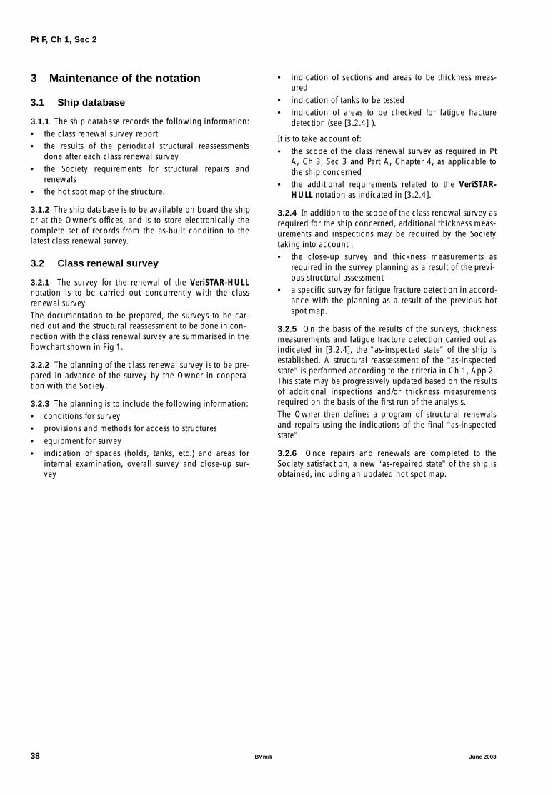
3 Maintenance of the notation
3.1 Ship database
3.1.1 The ship database records the following information:• the class renewal survey report • the results of the periodical structural reassessments
done after each class renewal survey • the Society requirements for structural repairs and
renewals• the hot spot map of the structure.
3.1.2 The ship database is to be available on board the shipor at the Owner’s offices, and is to store electronically thecomplete set of records from the as-built condition to thelatest class renewal survey.
3.2 Class renewal survey
3.2.1 The survey for the renewal of the VeriSTAR-HULLnotation is to be carried out concurrently with the classrenewal survey. The documentation to be prepared, the surveys to be car-ried out and the structural reassessment to be done in con-nection with the class renewal survey are summarised in theflowchart shown in Fig 1.
3.2.2 The planning of the class renewal survey is to be pre-pared in advance of the survey by the Owner in coopera-tion with the Society.
3.2.3 The planning is to include the following information:• conditions for survey• provisions and methods for access to structures• equipment for survey• indication of spaces (holds, tanks, etc.) and areas for
internal examination, overall survey and close-up sur-vey
• indication of sections and areas to be thickness meas-ured
• indication of tanks to be tested• indication of areas to be checked for fatigue fracture
detection (see [3.2.4] ).
It is to take account of:• the scope of the class renewal survey as required in Pt
A, Ch 3, Sec 3 and Part A, Chapter 4, as applicable tothe ship concerned
• the additional requirements related to the VeriSTAR-HULL notation as indicated in [3.2.4].
3.2.4 In addition to the scope of the class renewal survey asrequired for the ship concerned, additional thickness meas-urements and inspections may be required by the Societytaking into account : • the close-up survey and thickness measurements as
required in the survey planning as a result of the previ-ous structural assessment
• a specific survey for fatigue fracture detection in accord-ance with the planning as a result of the previous hotspot map.
3.2.5 On the basis of the results of the surveys, thicknessmeasurements and fatigue fracture detection carried out asindicated in [3.2.4], the “as-inspected state” of the ship isestablished. A structural reassessment of the “as-inspectedstate” is performed according to the criteria in Ch 1, App 2.This state may be progressively updated based on the resultsof additional inspections and/or thickness measurementsrequired on the basis of the first run of the analysis.The Owner then defines a program of structural renewalsand repairs using the indications of the final “as-inspectedstate”.
3.2.6 Once repairs and renewals are completed to theSociety satisfaction, a new “as-repaired state” of the ship isobtained, including an updated hot spot map.
38 BVmili June 2003

Pt F, Ch 1, Sec 2
Figure 1 : Actions to be taken in connection with the Class Renewal Survey
C:\Mes documents\JF010102.abcmercredi 12 janvier 2000
14:16
Planning of the class renewal survey based on the existing Hot Spot Map recorded
within the ship data base
- Overall Survey
- Close-up survey
- Thickness measurements (systematically associated with the close-up survey)
- Detection of fractures and deformations
Structural reassessment of the AS-INSPECTED STATE based on the collected data (the
reassessment is repeated, if necessary, based on additional thickness measurements)
Updating of ship data base (AS-INSPECTED STATE)
Definition of a program for corrective actions, as necessary, using the results of the structural
reassessment based on repairs/renewals
Completion of class renewal survey by implementing repairs/renewals
Updating the system database (AS-REPAIRED STATE)
Planning, documentation, structural reassessments
Surveys
June 2003 BVmili 39

Pt F, Ch 1, Sec 3
SECTION 3 STAR-MACH
1 General
1.1 Application
1.1.1 The additional class notation STAR-MACH isassigned at the design stage or after construction, and main-tained during the service life, to ships complying with therequirements of this Section in accordance with Pt A, Ch 1,Sec 2, [5.3.4].
1.2 Definitions
1.2.1 Risk AnalysisThe procedures, for assessing ship’s conformity with theSociety’s Rules, are based on engineering analysis of datacollected, and subsequent risk management based on theperformed analysis. Risk analysis evaluates vessel’s machin-ery and equipment, along with the operational and mainte-nance procedures, for compliance against acceptancecriteria.
1.2.2 OperatorIn this Section, Operator means the Owner of the vessel orany other organization or person, such as the Manager, orthe Shipyard, or the Bareboat Charterer, who declares to bein charge of the maintenance of the ship.
1.2.3 Maintenance Management SystemThe prescriptive rules for class renewal survey are substi-tuted by a review and auditing procedure of the Operator’sMaintenance Plan, and its onboard implementation, for thedeclared operational profile. This process may encompassitems not necessarily within the scope of the machineryclassification. In this Section, the Maintenance Manage-ment System means the computerized support, as well asthe content, that is the maintenance plan and the historyrecords.
1.2.4 DatabasesThe STAR-MACH notation makes use of the Integral ShipsDatabase (ISDB). The ISDB contains the generic database(GDB) and ship-specific databases (SDB). The GDB con-tains data about generic equipment, while an SDB containsdata about a particular ship.
1.3 Scope
1.3.1 ContentsSTAR-MACH is an on-going process with a feedback fromexperience. The assignment and maintenance of the STAR-MACH notation reflects this process, and indicates that:
• Risk analysis has been performed for the vessel and itssystems, based on the application of operational andmaintenance procedures
• The Operator, by taking into account the results of therisk analysis, has installed and follows operational andmaintenance procedures
• The Operator is able to demonstrate (e.g.: documenta-tion, database) the effective implementation of the oper-ational and maintenance procedures.
1.3.2 Maintenance and inspectionsSTAR-MACH covers maintenance specified in Operator’sMaintenance Plan. This includes Operator’s corrective, peri-odic and condition-monitoring maintenance, as well asinspections.
2 Assignment of the notation
2.1 Documentation to be submitted
2.1.1 The Operator is to submit the following documenta-tion:• documents required to prepare the SDB and to perform
the risk analysis, see [2.1.2]• the Maintenance Plan, including information detailed in
[2.2.1],• the specification of the on-board computerized system
used for maintenance management, see [2.2.2].
2.1.2 The documents required to prepare the SDB and toperform the risk analysis include specifications and opera-tional description of systems/components.These documents are used to model the ship. This model isstored in the SDB.
A typical list of the systems to be such documented is pre-sented below:• Navigation Instrumentation• Propulsion Plant• Electricity Production and Distribution• Cooling Water Systems• Lubricating Oil Systems• Fuel Oil Systems• Compressed Air Systems• Hydraulic Oil Systems• Automation• Bilge System• Ballast System / Trimming / Heeling• Fire Prevention Systems• Fire Detection System• Fire Fighting Systems• Fuel / Lubricating Oil Drainage / Recovery• Exhaust Gas Systems• Steam Production and Distribution• Thermal Oil Heating System
40 BVmili June 2003

Pt F, Ch 1, Sec 3
• Anchoring and Mooring Arrangements
• Steering Gear
• Cargo Equipment
• Air Ventilation and Conditioning
• Crew/Passengers Life Support
• Waste Treatment
• Sewage System.
2.2 Maintenance Management System
2.2.1 Maintenance Plan
The Operator is to provide a Maintenance Plan representingthe collection of maintenance tasks together with the sched-ule of execution.
The Maintenance Plan must include those items the suddenfailure of which in operation would affect the ship missionor the environment.
For these items, the following information must be madeavailable:
• maintenance type (inspection, reconditioning)
• maintenance frequency (periodicity value unit is to beclearly specified, i.e. hour, day, week, month, year)
• maintenance scope.
The frequency of maintenance and its scope should be justi-fied by Manufacturer’s recommendations or from docu-mented experience.
2.2.2 Computerized support
The Operator is to provide on board the ship a computer-ized system for maintenance management.
The approved Maintenance Plan is to be installed in thecomputerized system by the Operator.
The computerized system is to include:
• facilities for communication and exchange of data withOperator’s Office
• a system of back up such that the data can be readilyrestored, if needed, without loss of essential informa-tion.
Access to the database must be logged, controlled andsecured.
2.3 Interventions of the Society
2.3.1 Initial Risk Analysis
After the STAR-MACH notation has been requested, theSociety performs the Initial Risk Analysis of the ship basedon the submitted documentation.
The risk analysis identifies critical items which are listed incompliance with ISM Code, Section 10.
2.3.2 Maintenance Plan Approval
Once critical items have been analysed for the acceptanceof risks resulting from their failures, the ship’s MaintenancePlan is amended as necessary for approval.
2.3.3 Initial Audit on board
An Initial Audit is carried out, on board the ship, after theapproval of the Maintenance Plan. This audit verifies theinstallation of the computerized system, including Mainte-nance Plan on board.
2.3.4 STAR-MACH notation assignment
If the Initial Audit is satisfactory, the STAR-MACH notationis granted.
3 Maintenance of the notation
3.1 General
3.1.1 Actions by the Operator
The maintenance of the STAR-MACH notation requires thatthe Operator:
• records maintenance and operational data
• on request, provides the Society with recordings
• calls the Society for its interventions as stated in [3.1.2]
• takes corrective actions as necessary and whenrequested by the Society further to its analysis of thesubmitted data, Annual Performance Audits, andAnnual Shipboard Audits
• notifies the Society as soon as a condition requiringamendments to the Maintenance Plan is reached.
3.1.2 Interventions of the Society
The maintenance of the STAR-MACH notation is subject tothe following satisfactory audits and interventions:
• Initial Procedure:
- Initial Audit at the Operator’s Office
• Periodical Audits and interventions:
- Annual Shipboard Audit
- Annual Performance Audit at the Operator’s Office
- Annual Risk Analysis Review
• Occasional Audits.
In addition, reference is to be made to Pt A, Ch 2, Sec 2,[5.5] for class renewal survey of machinery items.
3.2 Chief Engineer authorization
3.2.1 Management on board
Maintenance on board is managed by the Chief Engineer,assisted, where necessary, by the appropriate Officer. Theresponsibility remains with the Chief Engineer.
3.2.2 Conditions
Each Chief Engineer Officer appointed to a vessel with theSTAR-MACH notation must be authorized by the Societyaccording to the conditions given in Pt A, Ch 2, App 2, [1].
June 2003 BVmili 41

Pt F, Ch 1, Sec 3
3.2.3 SuspensionThe Society may suspend the authorization of the ChiefEngineer:• according to the provisions of Pt A, Ch 2, App 2, [6.1.1]• in case there is repetitive evidence of non-compliance
with the approved Maintenance Plan.
3.3 Initial intervention
3.3.1 Initial Audit of the Operator’s OfficeThe Initial Audit of the Office is conducted six months afterthe first vessel of the Operator has been assigned the STAR-MACH notation with a window of plus or minus threemonths. The purpose of the audit is to verify the process ofcommunication and control in the Operator’s Office of theMaintenance Plan implemented on board the vessel(s).
3.4 Periodical audits and interventions
3.4.1 Annual Shipboard AuditAn Annual Shipboard Audit is performed, at the same timeas the Annual Class Survey.
The Surveyor verifies, to his satisfaction, the consistencyand implementation of the Maintenance Plan and crew’sfamiliarity with it. He also collects maintenance historiesand/or modifications to the Maintenance Plan.
3.4.2 Annual Performance Audit at the Operator’sOffice
Annually, a Performance Monitoring is held at the Opera-tor’s Office.
The Surveyor examines maintenance records (preventiveand corrective) concerning all vessels having the STAR-MACH notation. He also collects maintenance historiesand/or modifications to the Maintenance Plan of these ves-sels.
3.4.3 Annual Risk Analysis ReviewFrom the data collected during these audits, if needed, aRisk Analysis Review is done. This may lead to requireamendments to the Maintenance Plan.
3.5 Occasional Audits
3.5.1 Occasional audits may be performed in the followingcases:• amendment of the Maintenance Plan, see [3.6] • when the shipboard Maintenance Plan has not been
found in line with the approved one
• significant damage or malfunction of the equipment;when equipment is class related, an occasional surveyaccording to Pt A, Ch 2, Sec 2, [7.2]is to be requestedby the Operator.
3.5.2 Non-conformities raised or put to the attention of theSurveyor during audits lead to request for corrective actionsto be conducted within a delay to be fixed by the Surveyor.
3.5.3 The Operator is to inform the Society when majormaintenance stops are planned in order that a vertical serv-ice audit may be conducted by the Society during the main-tenence period.
The Surveyor may request a vertical service audit to be con-ducted at any time during the maintenance being per-formed in accordance with the Maintenance Plan.
3.6 Amendments to the Maintenance Plan
3.6.1 Amendments to the Maintenance Plan are to be car-ried out as necessary by the Operator in case of changes inship operation or equipment modification.
Such amendments are to be submitted to the Society.
3.6.2 Maintenance Plan is also to be amended in case ofabnormal frequency of equipment failures. The amend-ments are to be documented and submitted to the Society.
4 Termination
4.1 Conditions
4.1.1 Withdrawal
Repeated or major non-conformities affecting the mainte-nance of the STAR-MACH notation could lead to its with-drawal.
4.1.2 Cancellation
The STAR-MACH notation may be cancelled at any time theOperator wishes so.
4.1.3 Phasing out
In case of withdrawal or cancellation of the notation, theclass renewal survey of machinery will revert to the systemas requested by the Operator (normal, continuous survey orPlanned Maintenance Scheme) and the appropriate docu-mentation issued and/or amended, in order to maintain theclass of the ship.
42 BVmili June 2003

Pt F, Ch 1, App 1
APPENDIX 1 ACCEPTANCE CRITERIA FOR ISOLATED AREAS
OF ITEMS
1 General
1.1 Application
1.1.1 The acceptance criteria consist in checking that thethickness diminution of an isolated area of an item (meas-ured according to Ch 1, Sec 1, [4.3.2]) is less than theacceptable limits specified in [1.1.2]. Otherwise, actionsaccording to Ch 1, Sec 1, [4.3.2] are to be taken.
1.1.2 The acceptable limits for the thickness diminution ofisolated areas of items contributing to the hull girder longi-tudinal strength are specified in:• Tab 1 for the bottom zone items• Tab 2 for the neutral axis zone items• Tab 3 for the deck zone items.
The acceptable limits for the thickness diminution of iso-lated areas of items not contributing to the hull girder longi-tudinal strength are specified in Tab 4.
Table 1 : Acceptable limits for the thickness diminution of isolated areas of itemsItems contributing to the hull girder longitudinal strength and located in the bottom zone
Table 2 : Acceptable limits for the thickness diminution of isolated areas of itemsItems contributing to the hull girder longitudinal strength and located in the neutral axis zone
ItemAcceptable limit
L < 90 m L ≥ 90 m
Plating of:• keel, bottom and bilge• inner bottom• lower strake of inner side and longitudinal bulkheads• hopper tanks
22% 18%
Longitudinal ordinary stiffeners of:• keel, bottom and bilge• inner bottom• lower strake of inner side and longitudinal bulkheads• hopper tanks
Web 22% 18%
Flange 18% 15%
Longitudinal primary supporting members Web 22% 18%
Flange 18% 15%
ItemAcceptable limit
L < 90 m L ≥ 90 m
Plating of:• side• inner side and longitudinal bulkheads• ‘tweendecks
22% 18%
Longitudinals ordinary stiffeners of:• side• inner side and longitudinal bulkheads• ‘tweendecks
Web 22% 18%
Flange 18% 15%
Longitudinal primary supporting members Web 22% 18%
Flange 18% 15%
June 2003 BVmili 43
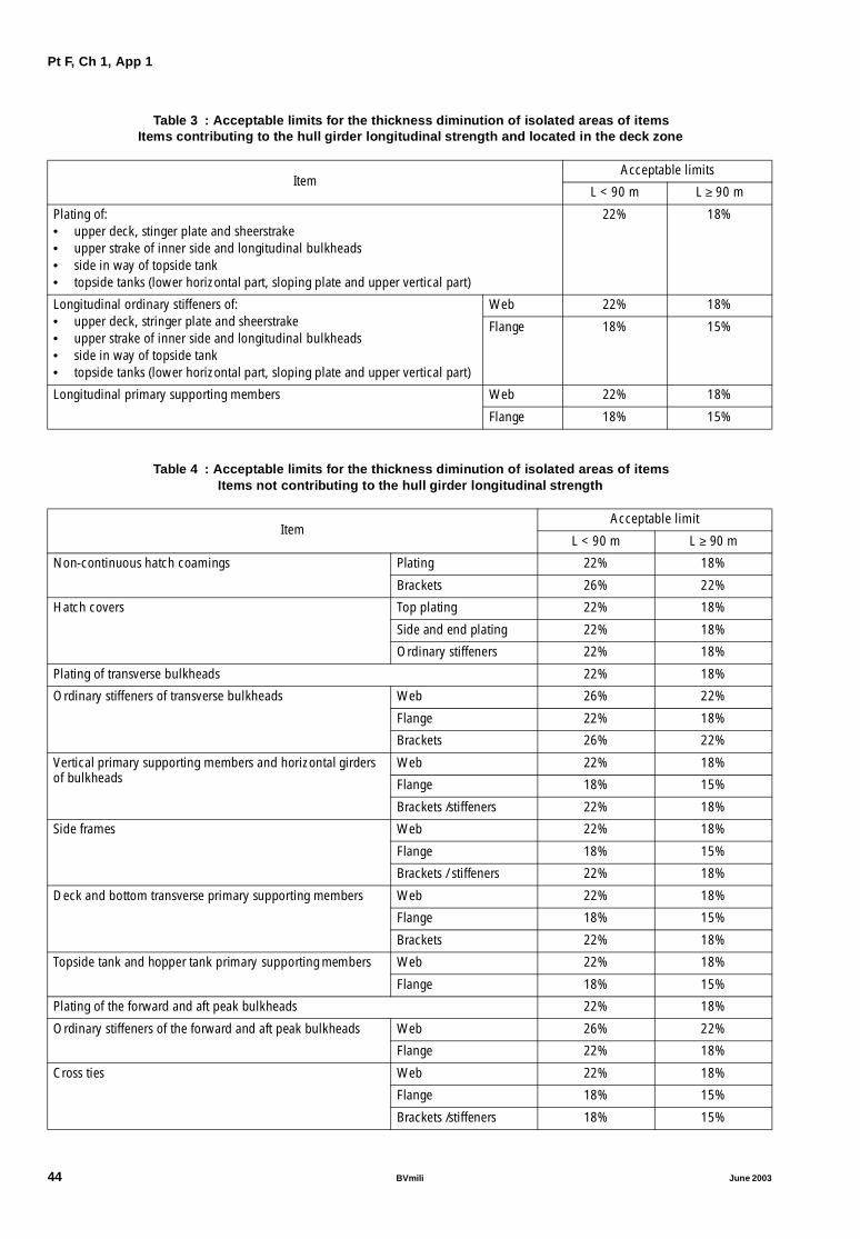
Pt F, Ch 1, App 1
Table 3 : Acceptable limits for the thickness diminution of isolated areas of itemsItems contributing to the hull girder longitudinal strength and located in the deck zone
Table 4 : Acceptable limits for the thickness diminution of isolated areas of itemsItems not contributing to the hull girder longitudinal strength
ItemAcceptable limits
L < 90 m L ≥ 90 m
Plating of:• upper deck, stinger plate and sheerstrake• upper strake of inner side and longitudinal bulkheads• side in way of topside tank• topside tanks (lower horizontal part, sloping plate and upper vertical part)
22% 18%
Longitudinal ordinary stiffeners of:• upper deck, stringer plate and sheerstrake• upper strake of inner side and longitudinal bulkheads• side in way of topside tank• topside tanks (lower horizontal part, sloping plate and upper vertical part)
Web 22% 18%
Flange 18% 15%
Longitudinal primary supporting members Web 22% 18%
Flange 18% 15%
ItemAcceptable limit
L < 90 m L ≥ 90 m
Non-continuous hatch coamings Plating 22% 18%
Brackets 26% 22%
Hatch covers Top plating 22% 18%
Side and end plating 22% 18%
Ordinary stiffeners 22% 18%
Plating of transverse bulkheads 22% 18%
Ordinary stiffeners of transverse bulkheads Web 26% 22%
Flange 22% 18%
Brackets 26% 22%
Vertical primary supporting members and horizontal girders of bulkheads
Web 22% 18%
Flange 18% 15%
Brackets /stiffeners 22% 18%
Side frames Web 22% 18%
Flange 18% 15%
Brackets / stiffeners 22% 18%
Deck and bottom transverse primary supporting members Web 22% 18%
Flange 18% 15%
Brackets 22% 18%
Topside tank and hopper tank primary supporting members Web 22% 18%
Flange 18% 15%
Plating of the forward and aft peak bulkheads 22% 18%
Ordinary stiffeners of the forward and aft peak bulkheads Web 26% 22%
Flange 22% 18%
Cross ties Web 22% 18%
Flange 18% 15%
Brackets /stiffeners 18% 15%
44 BVmili June 2003

Pt F, Ch 1, App 2
APPENDIX 2 ACCEPTANCE CRITERIA FOR ISOLATED ITEMS
Symbols
tA : As-built thickness of plating, in mmtM : Measured thickness of plating, in mmtC : Corrosion additions, in mm, defined in Pt B, Ch
4, Sec 2, [3]tC1, tC2 : Corrosion additions, in mm, defined in Pt B, Ch
4, Sec 2, [3] for the two compartments sepa-rated by the plating under consideration. Forplating internal to a compartment, tC1 = tC2 = tC
tR : Overall renewal thickness, in mm, of plating, inmm, defined in: • [2.2.1] in general• [4.3.1] for the plating which constitutes pri-
mary supporting memberstR1 : Minimum renewal thickness, in mm, of plating
defined in [2.2.2]tR2 : Renewal thickness, in mm, of plating subjected
to lateral pressure or wheeled loads, i.e. thethickness that the plating of a ship in service isto have in order to fulfil the strength check,according to the strength principles in Pt B, Ch4, Sec 3, [1.1]. This thickness is to be calculatedas specified in [2.2.3]
tR3 : Compression buckling renewal thickness, inmm, i.e. the thickness that the plating of a shipin service is to have in order to fulfil the com-pression buckling check, according to thestrength principles in Pt B, Ch 4, Sec 3, [1.3.1].This thickness is to be calculated as specified in[2.2.4]
tR4 : Shear buckling renewal thickness, in mm, i.e.the thickness that the plating of a ship in serviceis to have in order to fulfil the shear bucklingcheck, according to the strength principles in PtB, Ch 4, Sec 3, [1.3.1]. This thickness is to beconsidered only for ships equal to or greaterthan 90 m in length and is to be calculated asspecified in [2.2.5]
tG : Rule gross thickness, in mm, of plating, definedin [2.2.6]
tA,W : As built thickness of ordinary stiffener web, inmm
tA,F : As built thickness of ordinary stiffener faceplate, in mm
tM,W : Measured thickness of ordinary stiffener web, inmm
tM,F : Measured thickness of ordinary stiffener faceplate, in mm
wM : Section modulus, in cm3, of ordinary stiffeners,to be calculated as specified in Pt B, Ch 4, Sec
3, [3.4] on the basis of the measured thick-nesses of web, face plate and attached plating
wR : Renewal section modulus, in cm3, of ordinarystiffeners i.e. the section modulus that an ordi-nary stiffener of a ship in service is to have tofulfil the yielding check, according to thestrength principle in Pt B, Ch 4, Sec 3, [1.2.1]
tR,W : Renewal thickness, in mm, of ordinary stiffenerweb, i.e. the web thickness that an ordinarystiffener of a ship in service is to have in order tofulfil the buckling check, according to thestrength principle in Pt B, Ch 4, Sec 3, [1.3.2].This thickness is to be calculated as specified in[3.2.2]
tR,F : Renewal thickness, in mm, of ordinary stiffenerface plate, i.e. the face plate thickness that anordinary stiffener of a ship in service is to havein order to fulfil the buckling check, accordingto the strength principle in Pt B, Ch 4, Sec 3,[1.3.2]. This thickness is to be calculated asspecified in [3.2.2]
wG : Rule gross section modulus, in cm3, of ordinarystiffeners, defined in [3.2.3]
WRR : Re-assessment work ratio, defined in [4.2.1]
WRA : As-built work ratio, defined in [4.2.2]
tR5 : Yielding renewal thickness, in mm, of primarysupporting members, i.e. the thickness that theplating which constitutes primary supportingmembers of a ship in service is to have in orderto fulfil the yielding check, according to thestrength principles in Pt B, Ch 4, Sec 3, [1.2.2].This thickness is to be calculated as specified in[4.3.2]
tR6 : Buckling renewal thickness, in mm, of primarysupporting members, i.e. the thickness that theplating which constitutes primary supportingmembers of a ship in service is to have in orderto fulfil the buckling check, according to thestrength principles in Pt B, Ch 4, Sec 3, [1.3.1].This thickness is to be calculated as specified in[4.3.3]
E : Young’s modulus, in N/mm2, to be taken equalto:
• for steels in general:
E = 2,06.105 N/mm2
• for stainless steels:
E = 1,93.105 N/mm2
ν : Poisson’s ratio. Unless otherwise specified, avalue of 0,3 is to be taken into account
June 2003 BVmili 45

Pt F, Ch 1, App 2
ReH : Minimum yield stress, in N/mm2, of the mate-rial, defined in Pt B, Ch 4, Sec 1, [2]
γm, γR, γK1, ... , γK9 : Partial safety factors, defined in [1].
1 Partial safety factors
1.1 General
1.1.1 The partial safety factors γm and γR are defined in:
• Pt B, Ch 7, Sec 1, [1.2] or Pt B, Ch 8, Sec 3, [1.2], asapplicable, for plating
• Pt B, Ch 7, Sec 2, [1.2] or Pt B, Ch 8, Sec 4, [1.2], asapplicable, for ordinary stiffeners
• Pt B, Ch 7, Sec 3, [1.4] or Pt B, Ch 8, Sec 5, [1.3], asapplicable, for primary supporting members.
1.2 Partial safety factors based on theincreased knowledge of the structure
1.2.1 General
The partial safety factors γK1, γK2, γK3, γK4, γK5, γK6 and γK7 takeinto account the increased knowledge of the structuralbehaviour obtained through the surveys carried out on in-service ship structures and verification of their perform-ances. Therefore, they have values equal to or less than 1,0and apply to reduce the partial safety factor on resistance,γR, adopted in the strength checks of new ships (see Part B,Chapter 7 or Part B, Chapter 8, as applicable).
1.2.2 Partial safety factors γK1, γK2, γK3 and γK4 forplating
These partial safety factors are to be calculated as specifiedin:• [2.2.2] for minimum thicknesses (γK1)• [2.2.3] for the strength checks of plate panels subjected
to lateral pressure or wheeled loads (γK2)
• [2.2.4] for the compression buckling strength checks(γΚ3)
• [2.2.5] for the shear buckling strength checks (γΚ4).
1.2.3 Partial safety factor γK5 for ordinary stiffenersThe partial safety factor for yielding checks of ordinary stiff-eners (γΚ5) is to be calculated as specified in [3.2.1].
1.2.4 Partial safety factors γK6, γK7, γK8 and γK9 forprimary supporting members
These partial safety factors are to be calculated as specifiedin:• [4.2.1] for reassessment structural analyses (γK6, γK7)• [4.3.2] for yielding strength checks (γK8)• [4.3.3] for buckling strength checks (γΚ9).
2 Acceptance criteria for plating
2.1 Application
2.1.1 GeneralThe acceptance criteria for measured thicknesses of plating,together with the application procedure to be adopted dur-ing the reassessment of hull structures, are indicated in Fig1.
Figure 1 : Acceptance criteria for measured thicknesses of plating and application procedure
Steel renewal required
No steel renewal required
HOT SPOT ITEM
t < tMM R
YES
YES
NO
NO
R RGt > t +0,25 (t - t )M
Thickness measurements t
46 BVmili June 2003

Pt F, Ch 1, App 2
2.2 Renewal thicknesses
2.2.1 Overall renewal thicknessThe overall renewal thickness is to be obtained, in mm,from the following formula:
tR = max (tR1, tR2, tR3, tR4)
2.2.2 Minimum renewal thicknessThe minimum renewal thickness is to be obtained, in mm,from the following formula:
tR1 = t1 γK1
where:t1 : Minimum net thickness, in mm, to be calcu-
lated as specified in Pt B, Ch 7, Sec 1, [2.2] or PtB, Ch 8, Sec 3, [2.2], as applicable
γK1 : Partial safety factor (see [1.2.2]):γK1 = NP Ψ1
without being taken greater than 1,0Np : Coefficient defined in Tab 1
2.2.3 Renewal thickness of plating subjected tolateral pressure or wheeled loads
The renewal thickness of plating subjected to lateral pres-sure or wheeled loads is to be obtained, in mm, from thefollowing formula:
where:t2 : Net thickness, in mm, to be calculated as speci-
fied in: • Pt B, Ch 7, Sec 1, [3] or Pt B, Ch 8, Sec 3,
[3], as applicable, for plating subjected tolateral pressure
• Pt B, Ch 7, Sec 1, [4] or Pt B, Ch 8, Sec 3,[4], as applicable, for plating subjected towheeled loads
where the hull girder stresses are to be calcu-lated considering the hull girder transverse sec-tions constituted by elements (plating, ordinarystiffeners, primary supporting members) havingtheir measured thicknesses and scantlings
γK2 : Partial safety factor (see [1.2.2]):γK2 = NP Ψ2
without being taken greater than 1,0Np : Coefficient defined in Tab 1
2.2.4 Compression buckling renewal thicknessThe compression buckling renewal thickness is to beobtained, in mm, from the following formula:
tR3 = t3 γK3
where:t3 : Net thickness to be obtained, in mm, from the
following formulae:
b : Length, in m, of the plate panel side, defined inPt B, Ch 7, Sec 1, [5.1.2] or Pt B, Ch 8, Sec 3,[5.1.2], as applicable
σx1 : In plane hull girder normal stress, in N/mm2 tobe calculated as specified in Pt B, Ch 7, Sec 1,[5.2.2] or Pt B, Ch 8, Sec 3, [5.2.2], as applica-ble, considering the hull girder transverse sec-tions as being constituted by elements (plating,ordinary stiffeners, primary supporting mem-bers) having their measured thicknesses andscantlings
ε, Κ1 : Coefficients defined in Pt B, Ch 7, Sec 1, [5.3.1]
γK3 : Partial safety factor (see [1.2.2]):
γK3 = NP Ψ3
without being taken greater than 1,0
Np : Coefficient defined in Tab 1
2.2.5 Shear buckling renewal thickness
The shear buckling renewal thickness is to be obtained, inmm, from the following formula:
tR4 = t4 γK4
where:
t4 : Net thickness to be obtained, in mm, from thefollowing formulae:
b : Length, in m, of the plate panel side, defined inPt B, Ch 7, Sec 1, [5.1.3]
τ1 : In plane hull girder shear stress, in N/mm2, to becalculated as specified in Pt B, Ch 7, Sec 1,[5.2.3], considering the hull girder transversesections as being constituted by elements (plat-ing, ordinary stiffeners, primary supportingmembers) having their measured thicknessesand scantlings
Κ2 : Coefficient defined in Pt B, Ch 7, Sec 1, [5.3.2]
γK4 : Partial safety factor (see [1.2.2]):
γK4 = NP Ψ4
without being taken greater than 1,0
Np : Coefficient defined in Tab 1
Ψ1 1 tC1 tC2+t1
-------------------+=
tR2 t2γK2=
Ψ2 1 tC1 tC2+t2
-------------------+=
t3bπ---
σx1γRγm12 1-ν2( )EK1ε
-------------------------------------------103= for γmγRσx1ReH
2--------≤
t3bπ---
3 1-ν2( )ReH2
EK1ε ReH-σx1γRγm( )------------------------------------------------103= for γmγRσx1
ReH
2-------->
Ψ3 1 tC1 tC2+t3
-------------------+=
t4bπ---
τ1γRγm12 1-ν2( )EK2
----------------------------------------103= for γmγRτ1ReH
2 3-----------≤
t4bπ---
3 1-ν2( )ReH2
EK2 ReH- 3τ1γRγm( )--------------------------------------------------103= for γmγRτ1
ReH
2 3----------->
Ψ4 1 tC1 tC2+t4
-------------------+=
June 2003 BVmili 47

Pt F, Ch 1, App 2
Table 1 : Coefficient NP
2.2.6 Rule gross thickness
The rule gross thickness is to be obtained, in mm, from thefollowing formula:
where t1, t2, t3 and t4 are the net thicknesses defined in[2.2.2], [2.2.3], [2.2.4] and [2.2.5], respectively.
3 Acceptance criteria for ordinary stiff-eners
3.1 Application
3.1.1 The acceptance criteria for measured scantlings ofordinary stiffeners, together with the application procedureto be adopted during the reassessment of hull structures, areindicated in Fig 2.
3.2 Renewal scantlings
3.2.1 Renewal section modulus
The renewal section modulus is to be obtained, in cm3,from the following formula:
wR = wY γK5
where:
wY : Net section modulus, in cm3, to be calculatedas specified in Pt B, Ch 7, Sec 2, [3], as applica-ble, where the hull girder stresses are to be cal-culated considering the hull girder transversesections constituted by elements (plating, ordi-nary stiffeners, primary supporting members)having their measured thicknesses and scant-lings
γK5 : Partial safety factor (see [1.2.3]):
γK5 = NS Ψ5
without being taken greater than 1,0
NS : Coefficient defined in Tab 2
α, β : Parameters, depending on the type of ordinarystiffener, defined in Pt B, Ch 4, Sec 2, Tab 1.
Table 2 : Coefficient NS
3.2.2 Renewal web and face plate thicknesses
The renewal web and face plate thicknesses are to beobtained, in mm, from the following formulae:
tR,W = hW / CW
tR,F = bF / CF
where:
hw : Web height, in mm
bf : Face plate breadth, in mm
CW, CF : Coefficients depending on the type and materialof ordinary stiffeners, defined in Tab 3.
In any case, the renewal web and face plate thicknesses areto be not less than those obtained according to Pt A, Ch 2,App 3, [4].
3.2.3 Rule gross section modulus
The rule gross section modulus is to be obtained, in cm3,from the following formula:
where:
α, β : Parameters, depending on the type of ordinarystiffener, defined in Pt B, Ch 4, Sec 2, Tab 1
wN,R : Net section modulus, in cm3, defined in [3.2.1].
PlatingCoefficient NP
L < 90 m L ≥ 90 m
In general, including that which constitutes web of primary supporting members 0,75 0,80
Plating which constitutes face plate of primary supporting members 0,80 0,85
Hatch coaming brackets 0,70 0,75
Cross ties of ships with the service notation oil replenishment ship 0,80 0,85
tG max t1 t2 t3 t4,,,( ) tc1 tc2+ +=
Ordinary stiffenersCoefficient NS
L < 90 m L ≥ 90 m
Flat bars and bulb profiles 0,75 0,80
Flanged profiles 0,80 0,81
Ψ5
1 βtC
wY
--------+
1 α tC–-----------------=
wGwR βtC+1 α tC–
---------------------=
48 BVmili June 2003

Pt F, Ch 1, App 2
Figure 2 : Acceptance criteria for measured scantlings of ordinary stiffeners and application procedure
4 Acceptance criteria for primary sup-porting members
4.1 Application
4.1.1 The acceptance criteria for measured scantlings ofprimary supporting members and the application procedureto be adopted during the reassessment of hull structures areindicated in Fig 3.
4.2 Work ratios
4.2.1 Reassessment work ratioThe reassessment work ratio is to be obtained from the fol-lowing formula:
WRR = max (γK6WRY, γK7WRB)
where:γK6 : Partial safety factor (see [1.2.4]):
γK6 = 0,9
γK7 : Partial safety factor (see [1.2.4]):γK7 = 1,0
WRY : Yielding work ratio, defined in [4.2.3]WRB : Buckling work ratio, defined in [4.2.4].
4.2.2 As-built work ratioThe as-built work ratio is to be obtained from the followingformula:
WRA = max (WRY, WRB)
where:WRY : Yielding work ratio, defined in [4.2.3]WRB : Buckling work ratio, defined in [4.2.4].
Table 3 : Coefficients CW and CF
Steel renewal required
No steel renewal required
HOT SPOT ITEM
t , t , tM M,W M,F
Scantling measurements
W < WM R
R RG
OR
AND
AND
OR
M,W R,Wt < t
M,F R,Ft < t
W > W + 0,25(W - W )M
M,W R,Wt > t + 0,25(t - t )
A,W R,W
t > t + 0,25(t - t )M,F R,F A,F R,F
YES
YES
NO
NO
Type of ordinary stiffenersCW CF
ReH = 235 ReH = 315 ReH = 355 ReH = 235 ReH = 315 ReH = 355
Flat bar 20 18 17,5 Not applicable
Bulb 56 51 49 Not applicable
With symmetrical face plate 56 51 49 34 30 29
With non-symmetrical face plate 56 51 49 17 15 14,5
Note 1: ReH is given in N/mm 2
June 2003 BVmili 49

Pt F, Ch 1, App 2
Figure 3 : Application procedure for reassessment of the hull structure
4.2.3 Yielding work ratioThe yielding work ratio is to be obtained from the followingformula:
where:
σVM : Equivalent stress, in N/mm2, to be calculated asspecified in Pt B, Ch 7, App 1, [5.1.2], consider-ing the hull structure as being constituted byelements (plating, ordinary stiffeners, primarysupporting members) having their measuredthicknesses and scantlings for the calculation of
WRR and net scantlings according to Pt B, Ch 4,Sec 2 for the calculation of WRA and renewalthickness
Ry : Minimum yield stress, in N/mm2, of the mate-rial, to be taken equal to 235/k N/mm2
k : Material factor, defined in Pt B, Ch 4, Sec 1,[2.3].
4.2.4 Buckling work ratioThe buckling element work ratio is to be obtained from thefollowing formula:
WRB = max (WRB1, WRB2, WRB3, WRB4)
Scantling measurementstM
STRUCTURAL ANALYSIS
STRUCTURAL ANALYSISUPDATE
WR > 0,975OR
t < 0,7t
R
M A
A
NO
NO
NO
NO
NO
YES
YES
YES
YES
YES
Damage found ?
ReinforcementDefinition
HOT SPOT ITEM
No steel renewalrequired
Steel renewalrequired
Repair withreinforcement
WR > 1,0
for the item affectedby the damage
Damage is foundOR
M Rt > t
M Rt > t
WRYγRγmσVM
Ry
---------------------=
50 BVmili June 2003

Pt F, Ch 1, App 2
where:WRB1 : Compression buckling work ratio:
WRB2 : Shear buckling work ratio:
WRB3 : Compression, bending and shear buckling workratio:
WRB4 : Bi-axial compression and shear buckling workratio:
σa, σb, τb: Normal and shear stresses, in N/mm2, definedin Pt B, Ch 7, Sec 1, [5.4]
σc,τc : Critical buckling stresses, in N/mm2, defined inPt B, Ch 7, Sec 1, [5.3]
F : Coefficient defined in Pt B, Ch 7, Sec 1, [5.4.4]Fc : Coefficient to be obtained from the following
formula:
σcomb : Combined stress in N/mm2, defined in Pt B, Ch7, Sec 1, [5.4.4]
σc,a, σc,b : Critical buckling stresses, in N/mm2, defined inPt B, Ch 7, Sec 1, [5.4.5]
n, Ra, Rb : Coefficients defined in Pt B, Ch 7, Sec 1,[5.4.5].
The above quantities are to be calculated considering thehull structure as being constituted by elements (plating,ordinary stiffeners, primary supporting members) havingtheir measured thicknesses and scantlings for the calcula-
tion of WRR and net scantlings according to Pt B, Ch 4, Sec2 for the calculation of WRA and renewal thickness.
4.3 Renewal scantlings
4.3.1 Overall renewal thicknessThe overall renewal thickness may be obtained withoutprior knowledge of the thickness measurements, from thefollowing formula, in mm:
tR = max (tRY, tRB, 0,7 tA)
4.3.2 Yielding renewal thicknessThe yielding renewal thickness is to be obtained, in mm,from the following formula:
tRY = tY γK8
where:tY : Net thickness to be obtained, in mm, from the
following formula:tY = [tA - 0,5 (tC1 + tC2)] WRY
WRY : Yielding work ratio, defined in [4.2.3]γK8 : Partial safety factor (see [1.2.4]):
γK8 = NP ΨY
Np : Coefficient defined in Tab 1
4.3.3 Buckling renewal thicknessThe buckling renewal thickness is to be obtained, in mm,from the following formula:
tRB = tB γK9
where:tB : Net thickness to be obtained, in mm, from the
following formula:
WRB : Buckling work ratio, defined in [4.2.4]γK9 : Partial safety factor (see [1.2.4]):
γK9 = NP ΨB
Np : Coefficient defined in Tab 1
WRB1γRγmσb
σc
-----------------=
WRB2γRγmτb
τ c
----------------=
WRB3FFc
----=
WRB4 γRγmσa
Raσc a,
-------------- n σb
Rbσc b,
--------------- n
+
1n---
=
for σcomb
F-------------
ReH
2γRγm
--------------:≤
Fc 1 =
for σcomb
F-------------
ReH
2γRγm
--------------:>
Fc4σcomb
ReH γRγm⁄----------------------- 1 σcomb
ReH γRγm⁄-----------------------–
=
ΨY 1 0 5 tC1 tC2+( ),tY
---------------------------------+=
tB tA 0 5 tC1 tC2+( ),–[ ] WRB3=
ΨB 1 0 5 tC1 tC2+( ),tB
---------------------------------+=
June 2003 BVmili 51

Pt F, Ch 1, App 3
52 BVmili June 2003
APPENDIX 3 ACCEPTANCE CRITERIA FOR ZONES
1 General
1.1 Application
1.1.1 The acceptance criteria consist in checking that thesectional area diminution of a zone (measured according toCh 1, Sec 1, [4.3.4]) is less than the acceptable limits speci-fied in [1.1.2]. Otherwise, actions according to Ch 1, Sec 1,[4.3.4] are to be taken.
1.1.2 The acceptable limits for the sectional area diminu-tion of zones are specified in Tab 1.
Table 1 : Acceptable limits for the sectional areadiminution of zones
Zone Acceptable limit
Bottom zone 7%
Neutral axis zone
Side 11%
Inner side and longitudinal bulkheads
11%
Deck zone 7%

Pt F, Ch 1, App 4
APPENDIX 4 OWNER’S HULL INSPECTION REPORTS
1 General
1.1
1.1.1 Application
As stated in Ch 1, Sec 1, [3.5], inspection reports are to beprepared by the Owner’s person responsible each time aninspection is carried out within the scope of the Inspectionand Maintenance Plan. Two models of inspection report areprovided for this purpose:
• one model for inspection of spaces (applicable toinspection of deck area structure, ballast tanks, drycargo holds and spaces, superstructures and otheraccessible compartments)
• one model for inspection of hull equipment (applicableto hatch covers and small hatches, deck equipment, seaconnections and overboard discharges).
One separate inspection report is to be issued for each dif-ferent space or equipment inspected.
1.1.2 Use of models
The Owner is to adapt these models, so far as practicableand appropriate, to the ship concerned, the spaces to beinspected and the existing equipment. However, the generalcontent of the report and its layout are to comply with themodels.
1.1.3 Ship database
Interested parties are reminded that, as stated in Ch 1, Sec1, [1.3], the inspection reports are to be processed andrecorded in the ship database which is to be installed onboard ship and at the Owner’s offices. Therefore, thesemodels are to be used as a guide for entering the collecteddata into the ship database, in an electronic form.
The recording in the ship database is to be such as to easilyretrieve the different reports pertaining the same spaces andequipment during the lifetime of the ship, or the reports ofinspections performed during a given period, or the reportsrelated to the same type of space or equipment.
The attached documentation referred to in [2.5] and [3.4]may be either kept in a separate paper file or electronicallyprocessed in the ship database through appropriate means.
2 Report for inspection of spaces
2.1 General
2.1.1 The model of Owner’s report for space inspection isgiven in Tab 1.
2.1.2 The report is divided into four parts:
• general identification data
• summary of findings and repairs for the different areas ofthe space and for the fittings in this space
• details of findings and repairs, as applicable
• additional documentation attached to the report.
2.2 Identification data
2.2.1 The identification data are to give the informationabout the space inspected, date and place of inspection andname of the person under whose responsibility the inspec-tion has been carried out.
2.2.2 The identification of the space is to be such that:
• it is easy to trace the space concerned, in particular incases where several identical spaces exist on the ship
• the same identification is used for the subsequentinspection reports pertaining to the same space.
2.3 Summary of findings and repairs
2.3.1 Each space inspected is divided into items corre-sponding to:
• the different boundaries of the space
• the internal structure of the space
• the fittings of the space.
For better understanding, the second column of the tablemay be used to clarify which elements belong to each itemor which fittings are concerned.
2.3.2 For each item, as applicable, the summary table is togive a general answer to the findings and to the possiblerepairs made.
• When coating condition is concerned, the answer is tobe either “no coating”, or “good”, or “fair”, or “poor”,as per the definition of such conditions given in Pt A, Ch2, Sec 2.
• Anode condition is to be answered by giving an esti-mated average loss of weight as a percentage, bearing inmind the acceptance criteria given in Ch 1, Sec 1, [4].
• The other columns (fractures, general corrosion, pit-ting/grooving, deformations, repairs) are to be answered“yes” or “no”, depending on whether or not suchdefect/repair has been found/performed.
• The column “other” is to be used to indicate whetheranother type of inspection has been carried out, such asthickness measurement, pressure test or working test.
June 2003 BVmili 53
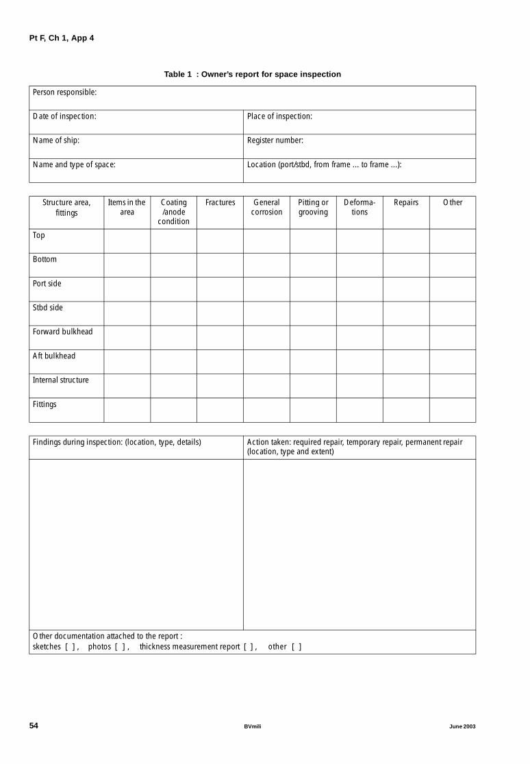
Pt F, Ch 1, App 4
Table 1 : Owner’s report for space inspection
Person responsible:
Date of inspection: Place of inspection:
Name of ship: Register number:
Name and type of space: Location (port/stbd, from frame ... to frame ...):
Structure area,fittings
Items in the area
Coating /anode
condition
Fractures General corrosion
Pitting or grooving
Deforma-tions
Repairs Other
Top
Bottom
Port side
Stbd side
Forward bulkhead
Aft bulkhead
Internal structure
Fittings
Findings during inspection: (location, type, details) Action taken: required repair, temporary repair, permanent repair (location, type and extent)
Other documentation attached to the report :sketches [ ] , photos [ ] , thickness measurement report [ ] , other [ ]
54 BVmili June 2003

Pt F, Ch 1, App 4
2.4 Details of findings and repairs
2.4.1 Each time the answer in the summary table is “poor”for coating, or “yes” for other topics, this part of the report isto be used to give details on the findings, defects or repairsconcerned.
2.4.2 As guidance, the following details are to be given:
• for coating found in poor condition: structural elementsconcerned, type of coating defect (breakdown, hardscale)
• for fractures: location of fractures, dimension, numberof identical fractures
• for general corrosion: structural elements concerned,extent of wastage on these elements, estimation of wast-age (if thickness measurements have been taken)
• for pitting/grooving: structural elements concerned andlocation, depth of pitting/grooving, percentage ofaffected surface using diagrams in Pt A, Ch 2, App 3,length of grooving
• for deformations: type of deformation (buckling, exter-nal cause), location of the deformation and structuralelements concerned, estimation of size
• for repairs (if performed without the attendance of a Sur-veyor, when this is possible or acceptable): type ofrepairs, elements or areas concerned.
2.5 Attached documentation
2.5.1 It is recommended that the report is supported byattaching sketches, photos, the thickness measurementreport or other documentation, when this is deemed neces-sary to clarify the findings and/or repairs given in thedetailed part.
For example:
• photos may be used to show the condition of the coat-ing and anodes, the extent of general corrosion, pittingand grooving, or the appearance and extent of fractures
• sketches may be used to indicate fractures, deformationsand repairs, especially when a photo cannot encompassthe whole image and give a complete representation.
3 Report for inspection of equipment
3.1 General
3.1.1 The model of Owner’s report for equipment inspec-tion is given in Tab 2.
3.1.2 The report is divided into three parts:
• general identification data
• detailed report of findings and repairs
• additional documentation attached to the report.
3.2 Identification data
3.2.1 The identification data are to give the informationabout the equipment inspected, date and place of inspec-tion and name of the person under whose responsibility theinspection has been carried out.
3.2.2 The identification of the equipment is to be such that:
• it is easy to trace the item of equipment concerned, inparticular in cases where several identical items ofequipment exist on the ship
• the same identification is used for the subsequentinspection reports pertaining to the same item of equip-ment.
3.3 Detailed report
3.3.1 The detailed report of inspection is divided into threeparts:
• inspection done:
- the type of inspection carried out: visual externalexamination, internal examination after dismantling,overhaul
- readings performed, when applicable: clearances,thickness measurements, working pressure, or otherworking parameters of the equipment
- findings during the inspection: corrosion, fractures,pieces of equipment worn out, broken or missing.
• maintenance done, repairs carried out and piecesrenewed
• results of tests performed after the inspection, such asworking test, pressure test, hose test or equivalent forhatch covers or other weathertight fittings, sea trials.
3.4 Attached documentation
3.4.1 It is recommended that the report is supported byattaching sketches, photos, the thickness measurementreport or other documentation, when this is deemed neces-sary to clarify the findings and/or repairs given in thedetailed part.
For example:
• photos may be used to show the condition of the piecesof equipment before their overhaul or renewal, the coat-ing condition of piping, or the extent of corrosion
• sketches may be used to indicate fractures and deforma-tions, clearances taken, or other measurements per-formed.
June 2003 BVmili 55

Pt F, Ch 1, App 4
Table 2 : Owner’s report for equipment inspection
Person responsible:
Date of inspection: Place of inspection:
Name of ship: Register number:
Name and type of equipment: Location (port/stbd, at frame ..., ...):
Type of inspection, findings and readings:
Repairs, maintenance, pieces renewed:
Working tests, pressure test, trials, ... :
Other documentation attached to the report :sketches [ ] , photos [ ] , thickness measurement report [ ] , other [ ]
56 BVmili June 2003

Part FAdditional Class Notations
Chapter 2
AVAILABILITY OF MACHINERY (AVM)
SECTION 1 ALTERNATIVE PROPULSION SYSTEM (AVM-APS)
SECTION 2 DUPLICATED PROPULSION SYSTEM (AVM-DPS)
SECTION 3 INDEPENDENT PROPULSION SYSTEM (AVM-IPS)
APPENDIX 1 PROCEDURES FOR FAILURE MODES AND EFFECT ANALYSIS
June 2003 BVmili 57

58 BVmili June 2003

Pt F, Ch 2, Sec 1
SECTION 1 ALTERNATIVE PROPULSION SYSTEM (AVM-APS)
1 General
1.1 Application
1.1.1 The additional class notation AVM-APS is assigned inaccordance with Pt A, Ch 1, Sec 2, [5.4.2] to self propelledships arranged with means for alternative propulsion systemcomplying with the requirements of this section.
1.1.2 The alternative propulsion system is a system suitableto maintain the ship in operating conditions, with limita-tions as specified below.
In case of loss of the main propulsion system, or some otherOwner’s necessities, such as maintenance of some impor-tant items of the main propulsion or power generation sys-tems during navigation, the alternative propulsion systemmay be used either to allow the ship to reach the first suita-ble port or place of refuge, or to escape from severe envi-ronment, allowing minimum services for navigation, safety,preservation of cargo and habitability.
1.1.3 If the Owner’s intention is to use the alternative pro-pulsion system only for emergency, in case of the loss of themain propulsion system, the number of services may bereduced with respect to those listed in [1.2.1], as be consid-ered by the Society on case by case basis.
1.1.4 In the case it is the Owner’s intention to use the aux-iliary propulsion system during the normal operation of theship in conditions other than an emergency, the suffix NSwill be added to the class notation AVM-APS.
1.1.5 If no hazard can result from deteriorated cargo condi-tion, the NS notation suffix is not requested.
1.2 Coverage of AVM-APS notation
1.2.1 Applicability
The following requirements are applicable to ships havingan alternative propulsion system allowing, in the case ofany single failure of one of the items specified in [1.2.4] rel-ative to the propulsion or power generation system, the fol-lowing operating conditions to be achieved:
• Full load speed not less than 7 knots
• Range of 1000 nautical miles or range corresponding to1/2 of the range achievable with the full supply of fuel,whichever is the less
• Full steering capability
• Availability of safety systems (including fire fighting sys-tems, bilge system, navigating lights, communicationapparatus, life-saving appliances)
• Habitability conditions (including minimum lighting,ventilation, galleys, refrigerated stores, drinking water orevaporator services)
• Preservation of the cargo when NS notation suffix isgranted.
THERE ARE DIFFERENT OPINIONS ON THE DESIRABIL-ITY TO INCLUDE EXAMPLES OF “NORMAL SAFETY CON-DITIONS” AND “MINIMUM HABITABILITYCONDITIONS”.FROM ONE SIDE IT IS FELT THAT, CONSIDERING THATTHE REQUIREMENTS FOR A NOTATION IS SOME-THICNG DIFFERENT FROM THE NORMAL RULES, THEEXAMPLE IS EFECTIVE TO BETTER EXPALIN THE MEAN-ING OF THE NOTATION. IN PARTICULAR IN THIS CASETHE EXAMPLE IS IN LINE WITH SOLAS DEFINITIONS.FROM THE OTHERE SIDE IT IS FELT THAT TOO DETAILEDRULES MAY BE DANGEROUS, SPECIALLY WHEN THEYINCLUDE LISTS. IN PARTICULAR IN THIS CASE THEEXAMPLE IS IN LINE WITH SOLAS DEFINITIONS ANDTHEREFORE REDUNDANT.1.2.2 Services not available during operation of the
alternative propulsion system
The following services need not to be supplied during theoperation of the alternative propulsion system:
• Cargo handling system
• Ballast system needed for cargo handling operation only
• Bow thrusters
• Air conditioning
• Other non essential services (for instance stabilizers, fulllighting, amusement items).
1.2.3 Use of the alternative propulsion system incase of single failure
In order to grant AVM-APS, the alternative propulsion sys-tem is to be arranged in such a way that the ship can con-tinue its operation in the case of a single failure (as definedin [1.2.4]) of any component of the main propulsion orpower generation system. In such a condition the propul-sion may be supplied either by the main engine or by thealternative propulsion system, depending on the failed com-ponent and/or type of failure.
1.2.4 Single failure concept
a) In addition to the complete loss of the main propulsionengine, the following single failures are to be consid-ered:
• Any failure of a non-static component of systemswhich are necessary for the operation of the mainengine (i.e. prime movers, controls and monitoringof fuel oil system, lubricating oil system, cooling sys-tem, compressed air system)
• Any failure of heat exchangers, including heat gen-erators, necessary for propulsion (i.e. auxiliary boil-ers, fuel oil heaters, reduction gear, oil coolers)
• Any failure of any non-static component of fuel oiland lubricating oil transfer system
• Any failure of any of the power generating sets
• Any failure of any electric apparatus, including themain switchboard, electric motors, transformers, dis-tribution switchboards, panels.
June 2003 BVmili 59
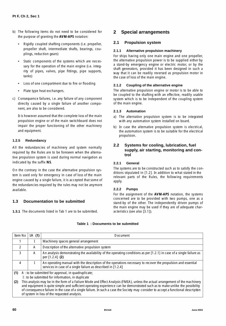
Pt F, Ch 2, Sec 1
b) The following items do not need to be considered forthe purpose of granting the AVM-APS notation:
• Rigidly coupled shafting components (i.e. propeller,propeller shaft, intermediate shafts, bearings, cou-plings, reduction gears)
• Static components of the systems which are neces-sary for the operation of the main engine (i.e. integ-rity of pipes, valves, pipe fittings, pipe supports,tanks)
• Loss of one compartment due to fire or flooding
• Plate type heat exchangers.
c) Consequence failures, i.e. any failure of any componentdirectly caused by a single failure of another compo-nent, are also to be considered.
It is however assumed that the complete loss of the mainpropulsion engine or of the main switchboard does notimpair the proper functioning of the other machineryand equipment.
1.2.5 Redundancy
All the redundancies of machinery and system normallyrequired by the Rules are to be foreseen when the alterna-tive propulsion system is used during normal navigation asindicated by the suffix NS.
On the contrary in the case the alternative propulsion sys-tem is used only for emergency in case of loss of the mainengine caused by a single failure, it is accepted that some ofthe redundancies required by the rules may not be anymoreavailable.
1.3 Documentation to be submitted
1.3.1 The documents listed in Tab 1 are to be submitted.
2 Special arrangements
2.1 Propulsion system
2.1.1 Alternative propulsion machinery
For ships having only one main engine and one propeller,the alternative propulsion power is to be supplied either bya stand-by emergency engine or electric motor, or by theshaft generators, provided it has been designed in such away that it can be readily reversed as propulsion motor inthe case of loss of the main engine.
2.1.2 Coupling of the alternative engineThe alternative propulsion engine or motor is to be able tobe coupled to the shafting with an effective, readily usablesystem which is to be independent of the coupling systemof the main engine.
2.1.3 Automation
a) The alternative propulsion system is to be integratedwith any automation system installed on board.
b) In case the alternative propulsion system is electrical,the automation system is to be suitable for the electricalpropulsion.
2.2 Systems for cooling, lubrication, fuelsupply, air starting, monitoring and con-trol
2.2.1 General
The systems are to be constructed such as to satisfy the con-ditions stipulated in [1.2]. In addition to what stated in therelevant parts of the Rules, the following requirementsapply.
2.2.2 PumpsFor the assignment of the AVM-APS notation, the systemsconcerned are to be provided with two pumps, one as astand-by of the other. The independently driven pumps ofthe main engine may be used if they are of adequate char-acteristics (see also [3.1]).
Table 1 : Documents to be submitted
Item No I/A (1) Document
1 I Machinery spaces general arrangement
2 A Description of the alternative propulsion system
3 A An analysis demonstrating the availability of the operating conditions as per [1.2.1] in case of a single failure as per [1.2.4] (2)
4 I An operating manual with the description of the operations necessary to recover the propulsion and essential services in case of a single failure as described in [1.2.4]
(1) A : to be submitted for approval, in quadruplicate; I : to be submitted for information, in duplicate
(2) This analysis may be in the form of a Failure Mode and Effect Analysis (FMEA), unless the actual arrangement of the machinery and equipment is quite simple and sufficient operating experience can be demonstrated such as to make unlike the possibility of consequence failure in the case of a single failure. In such a case the Society may consider to accept a functional description of system in lieu of the requested analysis.
60 BVmili June 2003

Pt F, Ch 2, Sec 1
2.2.3 Cooling system
The circuit for the main engine may be used provided that itcan be operated where the part relative to the main engineitself is cut off.
2.2.4 Lubrication system
The circuit of the alternative engine is to be independent ofthat for the main engine.
2.2.5 Fuel oil system
The circuit for the main engine may be used provided that:
a) Proper operation is ensured where the part relative tothe main engine itself is cut off;
b) It is supplied by a service tank other than that for themain engine;
c) Where more than one store tank and one service tankare available, means are to be provided to periodically
equalize the content on each set of tanks during theconsumption of the fuel.
2.2.6 Air starting system
If applicable, the circuit for the main engine may be usedprovided that proper operation is ensured where the partrelative to the main engine itself is cut off.
2.2.7 Monitoring and control system
These systems are to be independent of that for the mainengine (see also [2.1.3]).
2.2.8 By-pass
Means are to be provided to by-pass and shut-off each ofthe components which may be subject of a single failure, asdefined in [1.2.4], without impairing the functioning of thesystem itself (including machinery and equipment) or of theother systems which are to be operated in connection withnavigation.
Table 2 : Summary of alternative propulsion system requirementsfor delivery of the notations AVM-APS and AVM-APS-NS
Navigation condition Class notation AVM-APS Class notation AVM-APS-NS
Normal navigation Essential ship services (some non essential services may be shut-off, see [1.2.2])
Increased power generating capability requested in the case of electrical alternative propulsion system
Stand-by requested for power generating system
Redundancy of pumping capability requested forsystems necessary for alternative propulsion system functioning
Loss of main engine Essential services for ship safety Essential ship services (some non essential services may kept in service, for instance presevation of cargo)
Increased power generating capability requested in the case of electrical alternative propulsion system
Increased power generating capability requested in the case of electrical alternative propulsion system
No stand-by requested for power generating system Stand-by for power generating system not required, but available
No redundancy of pumping capability requested for systems necessary for main engine functioning
Redundancy of pumping capability for systemsnecessary for alternative propulsion system functioning not required, but available
Loss of any power generating set
No stand-by requested for power generating system No stand-by requested for power generating system
Redundancy of pumping capability requested for systems necessary for main engine functioning
Redundancy of pumping capability requested forsystems necessary for alternative propulsion system functioning
Loss of the main switchboard
Essential services for ship safety fed by emergency generator
Essential services for ship safety fed by emergencygenerator
Pumping system necessary for main propulsion fed by emergency generator or main engine driven pumps to be used
Pumping system necessary for alternative propulsion fed by emergency generator or main engine driven pumps to be used
No redundancy of pumping capability requested for systems necessary for main engine functioning
Redundancy of pumping capability for systemsnecessary for alternative propulsion system functioning not required
Any single failure of other equipment
Failed component replaced by stand-by component Failed component replaced by stand-by component
All other redundancies required by the rules are to be maintained
All other redundancies required by the rules are to be maintained
June 2003 BVmili 61

Pt F, Ch 2, Sec 1
2.3 Electrical installations
2.3.1 The following requirements shall be fulfilled:
a) Where the auxiliary propulsion system is supplied bythe main source of electrical power, the capacity of theother electric generators is to be that indicated in Pt C,Ch 3, Sec 3, [2.2], with the exception of those servicesindicated in [1.2.2], increased of the power requestedfor the alternative propulsion, without recourse to theemergency source of electrical power.
b) In the case the alternative propulsion system is intendedonly for emergency, the requirement in a) may beachieved without any stand-by generating set. However,when the notation suffix NS is requested, the requiremntin a) is to be achieved with any one of the generatingsets out of operation.
c) In case of loss of the main switchboard, all the essentialservices listed in [1.2.1] are to be supplied by the emer-gency generator, which should have an adequate powergenerating capacity
d) As an alternative to c), all the pumps necessary for thefunctioning of the main engine may be directly drivenby the engine, while the other services are supplied bythe emergency generator. No stand-by pumps are
requested for the systems relative to the main engine forthe time of the emergency.
e) Main switchboard is to be automatically separable intwo parts and each part is to fulfill the requirements.
2.4 Summary
2.4.1 A simplified description of the requirements to becomplied with for the assignment AVM-APS and AVM-APS-NS notations is given in Tab 2.
3 Tests on board
3.1 Running tests
3.1.1 The alternative propulsion system is to be subjectedto the running tests required by the Rules for similar sys-tems.
3.2 Sea trials
3.2.1 In the course of sea trials, the single failures men-tioned in [1.2.4] are to be simulated and the values of thepower and speed developed by the alternative propulsionsystem are to be recorded.WHILE IT IS FELT THAT THIS TABLE IS USEFUL TOEXPLAIN THE OVERALL PHILOSOPHY OF THIS SECTIONAND THAT IT SHOULD BE MADE AVAILABLE TO THESURVEYORS FOR THEIR GUIDANCE, THERE ARE DIFFER-ENT OPINIONS ON THE OPPORTUNITY TO INTRO-DUCE IT INTO THE RULES.IN FACT IT IS FELT THAT THIS TABLE COULD BE DAN-GEROUS, AS IT WOULD BE POSSIBLE THAT SOME POS-SIBLE ACTUAL EMERGENCY SITUATION MIGHT RESULTNOT COVERED BY ITS CONTENT. IN ADDITION ITSCONTENT APPEARS TOO TRIVIAL TO BE IN THE RULES.
62 BVmili June 2003

Pt F, Ch 2, Sec 2
SECTION 2 DUPLICATED PROPULSION SYSTEM (AVM-DPS)
1 General
1.1 Application
1.1.1 The additional class notation AVM-DPS is assigned inaccordance with Pt A, Ch 1, Sec 2, [5.4.3] to self propelledships arranged with means for duplicated propulsion systemcomplying with the requirements of this Section.
1.1.2 This notation applies to ships arranged with at leasttwo propellers and the associated independent shafting,each one independently driven by separate machinery, insuch a way that at least 50% of the power remains availablewhenever any of the propulsion machinery and the associ-ated propeller and shafting are out of service.
It is also applicable to ships arranged with at least two inde-pendent azimuth thrusters and any other equivalentarrangement.
1.2 Coverage of AVM-DPS notation
1.2.1 Applicability
The following requirements are applicable to ships having aduplicated propulsion system allowing, in the case of anysingle failure of one of the items specified in Ch 2, Sec 1,[1.2.4] relative to the propulsion or power generation sys-tem, the following operating conditions to be achieved:
THERE ARE DIFFERENT OPINIONS ON THE DESIRABIL-ITY TO INCLUDE EXAMPLES OF “NORMAL SAFETY CON-DITIONS” AND “MINIMUM HABITABILITYCONDITIONS”.FROM ONE SIDE IT IS FELT THAT, CONSIDERING THATTHE REQUIREMENTS FOR A NOTATION IS SOME-THICNG DIFFERENT FROM THE NORMAL RULES, THEEXAMPLE IS EFECTIVE TO BETTER EXPALIN THE MEAN-ING OF THE NOTATION. IN PARTICULAR IN THIS CASETHE EXAMPLE IS IN LINE WITH SOLAS DEFINITIONS.FROM THE OTHERE SIDE IT IS FELT THAT TOO DETAILEDRULES MAY BE DANGEROUS, SPECIALLY WHEN THEYINCLUDE LISTS. IN PARTICULAR IN THIS CASE THEEXAMPLE IS IN LINE WITH SOLAS DEFINITIONS ANDTHEREFORE REDUNDANT.• At least 50% of the power still available (in the case ofships with two propellers, this condition may beachieved either considering one propeller running atfull power, with the other propeller idle, or with the twopropellers running at 50% of the respective power,depending on the type of failure considered)
• Full load speed not less than 7 knots
• Range of 1000 nautical miles or range corresponding to1/2 of the range achievable with the full supply of fuel,whichever is the less
• Duplicated steering rudder and steering gear, or equiva-lent arrangement to ensure steering capability in case ofa major failure of the rudder or steering gear
• Availability of safety systems, including fire fighting sys-tems, bilge system, navigating lights, communicationapparatus, life-saving appliances
• Habitability conditions, including minimum lighting,ventilation and air conditioning for passenger ships, gal-leys, refrigerated stores, drinking water or evaporatorservices
• Preservation of the non-hazardous condition of thecargo.
1.2.2 Services not available during emergencyoperation of the duplicated propulsion system
The following services need not to be supplied during theemergency operation of one (or more) of the propulsion sys-tems, when any of the propulsion system is not availabledue to a single failure of any component of the propulsionplant or of any of the auxiliaries and equipment necessaryfor the propulsion:• Cargo handling system• Ballast system needed for cargo handling operation only• Bow thrusters• Air conditioning for cargo ships• Other non essential services (for instance stabilizers, full
lighting, amusement items).
1.2.3 Use of the duplicated propulsion system incase of single failure
In order to grant AVM-DPS, the duplicated propulsion sys-tem is to be arranged in such a way that the ship can con-tinue or can recover in such as short time, as not to impairthe safety of the ship, its operation in the case of a single fail-ure (as defined in Ch 2, Sec 1, [1.2.4]) of any component ofthe main propulsion, steering or power generation system.
1.2.4 Single failure concepta) A single failure of static and non-static components of
the propulsion, steering and power generation systemsis to be considered. Consequence failures, i.e. any fail-ure of any component directly caused by a single failureof another component, are also to be considered.
b) The loss of one compartment due to fire or flooding isnot to be considered as a single failure. Accordingly,duplicated apparatus, such as for instance main propul-sion machinery, electric power generators, different sec-tions of the main switchboard, duplicated steeringgears, etc. may be installed in the same compartment.
1.2.5 RedundancyIn the case the duplicated propulsion system is used underan emergency due to a single failure of any equipment orsystem, it is accepted that some of the redundanciesrequired normally by the rules may not be anymore availa-ble.
However, in the case the Owner wishes to operate the shipwith one of the propulsion system out of service, for anyoperative choice, all the redundancies of machinery andsystems normally required by the Rules during normal navi-gation are to be kept available.
1.3 Documentation to be submitted
1.3.1 The documents listed in Tab 1 are to be submitted.
June 2003 BVmili 63

Pt F, Ch 2, Sec 2
Table 1 : Documents to be submitted
2 Special arrangements
2.1 Systems for cooling, lubrication, fuelsupply, air starting, monitoring and con-trol
2.1.1 General
The systems are to be constructed such as to satisfy the con-ditions stipulated in Ch 2, Sec 1, [1.2]. In addition to whatstated in the relevant parts of the Rules, the followingrequirements apply.
2.1.2 Pumps
For the assignment of the AVM-DPS notation, the systemsconcerned are to be provided with at least two pumps, oneas a stand-by of the other. One of the two pumps may bedriven by the propulsion machinery, while the other pumpis to be independently driven.
2.1.3 Cooling system
In general, separate cooling systems are to be provided foreach main propulsion system, unless the FMEA demon-strates that one single cooling system serving all propulsionsystems is arranged in such a way that any single failure ofthe system does not make inoperative all the propulsion sys-tems at the same time.
2.1.4 Lubricating oil system
Each main propulsion system is to be fitted with a separatelubrication oil system.
2.1.5 Fuel oil system
At least two store tanks and two service tanks are to be fit-ted. Means are to be provided to periodically equalize thecontent on each set of tanks during the consumption of thefuel, in order to achieve the minimum range indicated in1.2.1 after a single failure:
2.1.6 By-pass
Means are to be provided to by-pass and shut-off each ofthe components which may be subject of a single failure, asdefined in Ch 2, Sec 1, [1.2.4], without impairing the func-tioning of the system itself (including machinery and equip-
ment) or of the other systems which are to be operated inconnection with navigation in emergency.
2.2 Rudders and steering gears
2.2.1 The following requirements shall be fulfilled:
a) A duplicated rudder and steering gear are to bearranged, unless the arrangement of the main propul-sion system allows the same manoeuvrability requestedby the rules in case of single failure that may prevent theuse of the normal steering system, such as ships withtwo independent controllable pitch propellers, shipswith azimuth thrusters or PODs, ships with fore and aftside thrusters.
b) Where ships do not have traditional rudder and steeringgears, being their steering capability supplied by azi-muth thrusters or equivalent features, means are to beprovided to allow at least the same redundancy asrequired in a) above.
2.3 Electrical installations
2.3.1 The following requirements shall be fulfilled:
a) The electrical generators are to be arranged in such away that any single failure cannot put out of servicemore than one generating set at one time. However, sin-gle failures leading to the loss of more than one generat-ing set at one time may be accepted, provided the FMEAdemonstrates that, after the failure, enough power stillremains available to operate the ship under the condi-tions stated in [1.2.1] without any stand-by generatingset.
b) Where the power is supplied to all the auxiliary neces-sary for propulsion through a single main switchboard,the switchboard is to be arranged in at least two sectionswith all circuits properly distributed between the sec-tions. In case of short circuit in one of the two sections,the second section is to be capable to be automaticallydisconnected.
c) In case of loss of the main switchboard, all the essentialservices listed in Ch 2, Sec 1, [1.2.1] are to be suppliedby the emergency generator, which should have an ade-quate power generating capacity.
Item No I/A (1) Document
1 I Machinery spaces general arrangement
2 A Description of the duplicated propulsion system
3 A An analysis demonstrating the availability of the operating conditions as per Ch 2, Sec 1, [1.2.1] in case of a sin-gle failure as per Ch 2, Sec 1, [1.2.4] (2)
4 I An operating manual with the description of the operations necessary to recover the propulsion and essential services in case of a single failure as described in Ch 2, Sec 1, [1.2.4]
(1) A : to be submitted for approval, in quadruplicate;I : to be submitted for information, in duplicate
(2) This analysis may be in the form of a Failure Mode and Effect Analysis (FMEA). Ch 2, App 1 describes an acceptable procedure for carrying out the FMEA.
64 BVmili June 2003

Pt F, Ch 2, Sec 2
d) As an alternative to c), all the pumps necessary for thefunctioning of the main engine may be directly drivenby the engine, while the other services are supplied bythe emergency generator. No stand-by pumps arerequested for the systems relative to the main engine forthe time of the emergency.
2.4 Automation
2.4.1 The automation system is to be arranged in such away as to prevent the possibility that a single failure of thecontrol system may lead to the loss of more than one pro-pulsion system.
3 Tests on board
3.1 Running tests
3.1.1 The duplicated propulsion system is to be subjectedto the running tests required by the Rules for similar sys-tems.
3.2 Sea trials
3.2.1 In the course of sea trials the single failures men-tioned in Ch 2, Sec 1, [1.2.4] are to be simulated and thevalues of the power and speed developed in this conditionare to be recorded.
June 2003 BVmili 65

Pt F, Ch 2, Sec 3
SECTION 3 INDEPENDENT PROPULSION SYSTEM (AVM-IPS)
1 General
1.1 Application
1.1.1 The additional class notation AVS-IPS is assigned inaccordance with Pt A, Ch 1, Sec 2, [5.4.4] to self propelledships arranged with means for independent propulsion sys-tems complying with the requirements of this Section.
1.1.2 This notation is granted, provided that :
a) The ship is arranged with at least two propellers and theassociated independent shafting, each one independ-ently driven by separate machinery, in such a way thatat least 50% of the power remains available wheneverany of the propulsion machinery and the associated pro-peller and shafting are out of service.
It is also applicable to ships arranged with at least twoindependent azimuth thrusters and any other equivalentarrangement.
b) The propulsive installations are arranged in differentcompartments, in such a way that at least 50% of thepower installed on board is still available whenever themachinery arranged in any one compartment is notoperating
c) The arrangement of the independent propulsion systemis such as to allow the ship to reach the first suitable portor place of refuge, or to escape from severe environ-ment, providing the minimum services for navigation,preservation of cargo and habitability in case of any sin-gle failure.
1.2 Coverage of AVM-IPS notation
1.2.1 ApplicabilityThe following requirements are applicable to ships havingan independent propulsion system allowing, in the case ofany single failure of one of the items specified in Ch 2, Sec1, [1.2.4] relative to the propulsion or power generationsystem, the following operating conditions to be achieved:
• At least 50% of the power still available (in the case ofships with two propellers, this condition may beachieved either considering one propeller running atfull power, with the other propeller idle, or with the twopropellers running at 50% of the respective power,depending on the type of failure considered)
• Full load speed not less than 7 knots
• Range of 1000 nautical miles or range corresponding to1/2 of the range achievable with the full supply of fuel,whichever is the less
• Duplicated steering rudder and steering gear, or equiva-lent arrangement to ensure steering capability in case ofa major failure of the rudder or steering gear
• Availability of safety systems, including fire fighting sys-tems, bilge system, navigating lights, communicationapparatus, life-saving appliances
• Habitability conditions, including minimum lighting,ventilation and air conditioning for passenger ships, gal-leys, refrigerated stores, drinking water or evaporatorservices
• Preservation of the non hazardous condition of thecargo.
THERE ARE DIFFERENT OPINIONS ON THE DESIRABIL-ITY TO INCLUDE EXAMPLES OF “NORMAL SAFETY CON-DITIONS” AND “MINIMUM HABITABILITYCONDITIONS”.FROM ONE SIDE IT IS FELT THAT, CONSIDERING THATTHE REQUIREMENTS FOR A NOTATION IS SOME-THICNG DIFFERENT FROM THE NORMAL RULES, THEEXAMPLE IS EFECTIVE TO BETTER EXPALIN THE MEAN-ING OF THE NOTATION. IN PARTICULAR IN THIS CASETHE EXAMPLE IS IN LINE WITH SOLAS DEFINITIONS.FROM THE OTHERE SIDE IT IS FELT THAT TOO DETAILEDRULES MAY BE DANGEROUS, SPECIALLY WHEN THEYINCLUDE LISTS. IN PARTICULAR IN THIS CASE THEEXAMPLE IS IN LINE WITH SOLAS DEFINITIONS ANDTHEREFORE REDUNDANT.1.2.2 Services not available during emergency
operation of the duplicated propulsion systemThe following services need not to be supplied during theemergency operation of one (or more) of the propulsion sys-tems, when any of the propulsion system is not availabledue to a single failure of any component of the propulsionplant or of any of the auxiliaries and equipment necessaryfor the propulsion:• Cargo handling system• Ballast system needed for cargo handling operation only• Bow thrusters• Air conditioning for cargo ships• Other non essential services (for instance stabilizers, full
lighting, amusement items).
1.2.3 Use of the independent propulsion system incase of single failure
In order to grant AVM-IPS, the independent propulsion sys-tem is to be arranged in such a way that the ship can con-tinue or can recover in such as short time, as not to impairthe safety of the ship, its operation in the case of a singlefailure (as defined in Ch 2, Sec 1, [1.2.4]) of any componentof the main propulsion, steering or power generation sys-tem.
1.2.4 Single failure concept
a) A single failure of static and non-static components ofthe propulsion, steering and power generation systemsis to be considered. Consequence failures, i.e. any fail-ure of any component directly caused by a single failureof another component, are also to be considered.
b) The loss of one compartment due to fire or flooding.However, the collision in way of a bulkhead, and theconsequent loss of two adjacent compartments due toflooding is not to be considered as a single failure forthe purpose of the requirements in this Section.
66 BVmili June 2003
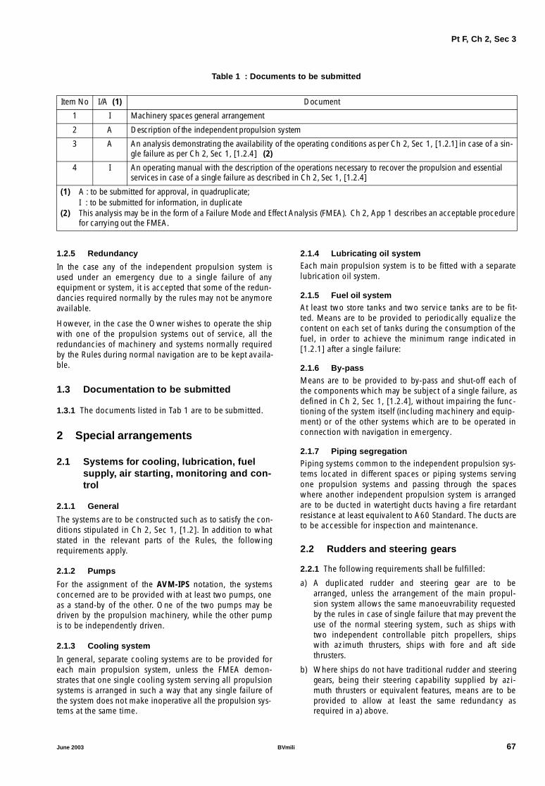
Pt F, Ch 2, Sec 3
Table 1 : Documents to be submitted
1.2.5 Redundancy
In the case any of the independent propulsion system isused under an emergency due to a single failure of anyequipment or system, it is accepted that some of the redun-dancies required normally by the rules may not be anymoreavailable.
However, in the case the Owner wishes to operate the shipwith one of the propulsion systems out of service, all theredundancies of machinery and systems normally requiredby the Rules during normal navigation are to be kept availa-ble.
1.3 Documentation to be submitted
1.3.1 The documents listed in Tab 1 are to be submitted.
2 Special arrangements
2.1 Systems for cooling, lubrication, fuelsupply, air starting, monitoring and con-trol
2.1.1 General
The systems are to be constructed such as to satisfy the con-ditions stipulated in Ch 2, Sec 1, [1.2]. In addition to whatstated in the relevant parts of the Rules, the followingrequirements apply.
2.1.2 Pumps
For the assignment of the AVM-IPS notation, the systemsconcerned are to be provided with at least two pumps, oneas a stand-by of the other. One of the two pumps may bedriven by the propulsion machinery, while the other pumpis to be independently driven.
2.1.3 Cooling system
In general, separate cooling systems are to be provided foreach main propulsion system, unless the FMEA demon-strates that one single cooling system serving all propulsionsystems is arranged in such a way that any single failure ofthe system does not make inoperative all the propulsion sys-tems at the same time.
2.1.4 Lubricating oil systemEach main propulsion system is to be fitted with a separatelubrication oil system.
2.1.5 Fuel oil systemAt least two store tanks and two service tanks are to be fit-ted. Means are to be provided to periodically equalize thecontent on each set of tanks during the consumption of thefuel, in order to achieve the minimum range indicated in[1.2.1] after a single failure:
2.1.6 By-pass
Means are to be provided to by-pass and shut-off each ofthe components which may be subject of a single failure, asdefined in Ch 2, Sec 1, [1.2.4], without impairing the func-tioning of the system itself (including machinery and equip-ment) or of the other systems which are to be operated inconnection with navigation in emergency.
2.1.7 Piping segregationPiping systems common to the independent propulsion sys-tems located in different spaces or piping systems servingone propulsion systems and passing through the spaceswhere another independent propulsion system is arrangedare to be ducted in watertight ducts having a fire retardantresistance at least equivalent to A60 Standard. The ducts areto be accessible for inspection and maintenance.
2.2 Rudders and steering gears
2.2.1 The following requirements shall be fulfilled:
a) A duplicated rudder and steering gear are to bearranged, unless the arrangement of the main propul-sion system allows the same manoeuvrability requestedby the rules in case of single failure that may prevent theuse of the normal steering system, such as ships withtwo independent controllable pitch propellers, shipswith azimuth thrusters, ships with fore and aft sidethrusters.
b) Where ships do not have traditional rudder and steeringgears, being their steering capability supplied by azi-muth thrusters or equivalent features, means are to beprovided to allow at least the same redundancy asrequired in a) above.
Item No I/A (1) Document
1 I Machinery spaces general arrangement
2 A Description of the independent propulsion system
3 A An analysis demonstrating the availability of the operating conditions as per Ch 2, Sec 1, [1.2.1] in case of a sin-gle failure as per Ch 2, Sec 1, [1.2.4] (2)
4 I An operating manual with the description of the operations necessary to recover the propulsion and essential services in case of a single failure as described in Ch 2, Sec 1, [1.2.4]
(1) A : to be submitted for approval, in quadruplicate;I : to be submitted for information, in duplicate
(2) This analysis may be in the form of a Failure Mode and Effect Analysis (FMEA). Ch 2, App 1 describes an acceptable procedure for carrying out the FMEA.
June 2003 BVmili 67

Pt F, Ch 2, Sec 3
2.3 Electrical installations
2.3.1 The following requirements shall be fulfilled:
a) The electrical generators are to be arranged in such away that any single failure cannot put out of servicemore than one generating set at one time. However, sin-gle failures leading to the loss of more than one generat-ing set at one time may be accepted, provided the FMEAdemonstrates that, after the failure, enough power stillremains available to operate the ship under the condi-tions stated in [1.2.1] without any stand-by generatingset. In general this requirement is to be achieved arrang-ing the electric generators in two separate compart-ments.
b) Where the power is supplied to all the auxiliary neces-sary for propulsion through a single main switchboard,the switchboard is to be arranged in at least two sectionswith all circuits properly distributed between the sec-tions. In case of short circuit in one of the two sections,the second section is to be capable to be automaticallydisconnected. The sections are to be separated by abulkhead.
c) In case of loss of the main switchboard, all the essentialservices listed in Ch 2, Sec 1, [1.2.1] are to be suppliedby the emergency generator, which should have an ade-quate power generating capacity.
d) As an alternative to c), all the pumps necessary for thefunctioning of the main engine may be directly drivenby the engine, while the other services are supplied by
the emergency generator. No stand-by pumps arerequested for the systems relative to the main engine forthe time of the emergency.
e) Electric cables and other electric apparatus serving amachinery space and passing through the spaces whereother independent propulsion systems are arranged areto be ducted in watertight ducts having a fire retardantresistance at least equivalent to A60 Standard. The ductsare to be accessible for inspection and maintenance.
REQUIREMENT RELATIVE TO MAIN SWITCHBOARDSHOULD BE FURTHERE CONSIDERED2.4 Automation
2.4.1 The automation system is to be arranged in such away as to prevent the possibility that a single failure of thecontrol system may lead to the loss of more than one pro-pulsion system.
3 Tests on board
3.1 Running tests
3.1.1 The independent propulsion system is to be subjectedto the running tests required by the Rules for similar sys-tems.
3.2 Sea trials
3.2.1 In the course of sea trials the single failures men-tioned in Ch 2, Sec 1, [1.2.4] are to be simulated and thevalues of the power and speed developed in this conditionare to be recorded.
68 BVmili June 2003

Pt F, Ch 2, App 1
APPENDIX 1 PROCEDURES FOR FAILURE MODES AND
EFFECT ANALYSIS
1 General
1.1 Introduction
1.1.1 FMEA requirement
As specified in Ch 2, Sec 1, Ch 2, Sec 2 and Ch 2, Sec 3 inorder to grant the AVM notations, an FMEA is to be carriedout, with the exception indicated in Note (2) of Ch 2, Sec 1,Tab 1 in case of single failure to the propulsion, steering andpower generating system, the ship is still capable to achievethe performances indicated in the applicable Sections as acondition for granting the notation.
1.1.2 Scope of the Appendix
This Appendix describes a failure mode and effects analysis(FMEA) and gives guidance as to how it may be applied by:
a) explaining basic principles
b) providing the procedural steps necessary to perform ananalysis
c) identifying appropriate terms, assumptions, measuresand failure modes, and
d) providing examples of the necessary worksheets.
1.1.3 Definition of FMEA
A practical, realistic and documented assessment of the fail-ure characteristics of the ship and its component systemsshould be undertaken with the aim of defining and studyingthe important failure conditions that may exist.
1.1.4 FMEA principles
The FMEA is based on a single failure concept under whicheach considered system at various levels of a system’s func-tional hierarchy is assumed to fail by one probable cause ata time. The effects of the postulated failure are analysed andclassified according to their severity. Such effects mayinclude secondary failures (or multiple failures) at otherlevel(s). Any failure mode which may cause a catastrophiceffect should be guarded against by system or equipmentredundancy unless the probability of such failure isextremely improbable. For failure modes causing hazardouseffects corrective measures may be accepted in lieu. A testprogramme should be drawn up to confirm the conclusionsof FMEA.
1.1.5 Alternatives
While FMEA is suggested as one of the most flexible analy-sis techniques, it is accepted that there are other methodswhich may be used and which in certain circumstancesmay offer an equally comprehensive insight into particularfailure characteristics.
1.2 Objectives
1.2.1 Primary objectiveThe primary objective of FMEA is to provide a comprehen-sive, systematic and documented investigation which estab-lishes the important failure conditions of the shippropulsion, steering and power generation systems, as wellas any other system requested by the Owner, and assessestheir significance with regard to the safety of the ship and itsoccupants.
1.2.2 Aim of the analysisThe main aims of undertaking the analysis are to:
a) provide ship and system designers with data to audittheir proposed designs
b) provide the Owner with the results of a study into ship’sselected systems failure characteristics so as to assist inan assessment of the arrangements and measures to betaken to limit the damages consequent of the failurewithin acceptable limits
c) provide the Master and crew of the ship with data togenerate comprehensive training, operational and main-tenance programmes and documentation.
1.3 Sister ships
1.3.1 For ships of the same design and having the sameequipment, one FMEA on any one of such ships may be suf-ficient, but each of the other ships are to be subject to thesame FMEA conclusion trials.
1.4 FMEA basics
1.4.1 Before proceeding with a detailed FMEA into theeffects of the failure of the system elements on the systemfunctional output it is necessary to perform a functional fail-ure analysis of the considered systems. In this way only sys-tems which fail the functional failure analysis need to beinvestigated by a more detailed FMEA.
1.4.2 Operational modesWhen conducting a system FMEA the following typicaloperational modes within the normal design environmentalconditions of the ships are to be considered:
a) normal seagoing conditions at full speed
b) maximum permitted operating speed in congestedwaters
c) manoeuvring alongside
d) seagoing conditions in emergency, as defined in Ch 2,Sec 1, Ch 2, Sec 2 and Ch 2, Sec 3.
June 2003 BVmili 69

Pt F, Ch 2, App 1
1.4.3 Functional interdependance
This functional interdependence of these systems is also tobe described in either block diagrams or fault tree diagramsor in a narrative format to enable the failure effects to beunderstood. As far as applicable, each of the systems to beanalysed is assumed to fail in the following failure modes:
a) complete loss of function
b) rapid change to maximum or minimum output
c) uncontrolled or varying output
d) premature operation
e) failure to operate at a prescribed time
f) failure to cease operation at a prescribed time.
Depending on the system under consideration other failuremodes may have to be taken into account.
1.4.4 Systems which can fail without catastrophiceffects
If a system can fail without any hazardous or catastrophiceffect, there is no need to conduct a detailed FMEA into thesystem architecture. For systems whose individual failurecan cause hazardous or catastrophic effects and where aredundant system is not provided, a detailed FMEA asdescribed in the following paragraphs should be followed.
Results of the system functional failure analysis should bedocumented and confirmed by a practical test programmedrawn up from the analysis.
1.4.5 Redundant systems
Where a system, the failure of which may cause a hazard-ous or catastrophic effect, is provided with a redundant sys-tem, a detailed FMEA may not be required provided that:
a) the redundant system can be put into operation or cantake over the failed system within the time-limit dictatedby the most onerous operational mode without hazard-ing the ship
b) the redundant system is completely independent fromthe system and does not share any common system ele-ment the failure of which would cause failure of boththe system and the redundant system. Common systemelement may be acceptable if the probability of failurecomplies with [4].
c) the redundant system may share the same power sourceas the system. In such case an alternative power sourceshould be readily available with regard to the require-ment of a) above.
The probability and effects of operator error to bring in theredundant system are also to be considered.
1.5 FMEA analysis
1.5.1 The systems to be subject to a more detailed FMEAinvestigation at this stage are to include all those that havefailed the system FMEA and may include those that have avery important influence on the safety of the ship and itsoccupants and which require an investigation at a deeperlevel than that undertaken in the system functional failureanalysis. These systems are often those which have been
specifically designed or adapted for the ship, such as thecraft’s electrical and hydraulic systems.
2 FMEA performance
2.1 Procedures
2.1.1 The following steps are necessary to perform anFMEA:
a) to define the system to be analysed
b) to illustrate the interrelationships of functional elementsof the system, by means of block diagrams
c) to identify all potential failure modes and their causes
d) to evaluate the effects on the system of each failuremode
e) to identify failure detection methods
f) to identify corrective measures for failure modes
g) to assess the probability of failures causing hazardous orcatastrophic effects, where applicable
h) to document the analysis
i) to develop a test programme
j) to prepare FMEA report.
2.2 System definition
2.2.1 The first step in an FMEA study is a detailed study ofthe system to be analysed, through the use of drawings andequipment manuals. A narrative description of the systemand its functional requirements is to be drawn up includingthe following information:
a) general description of system operation and structure
b) functional relationship among the system elements
c) acceptable functional performance limits of the systemand its constituent elements in each of the typical oper-ational modes
d) system constraints.
2.3 Development of system block diagram
2.3.1 Block diagramThe next step is to develop block diagram(s) showing thefunctional flow sequence of the system, both for technicalunderstanding of the functions and operation of the system,and for the subsequent analysis. As a minimum the blockdiagram is to contain:
a) breakdown of the system into major sub-systems orequipment
b) all appropriate labelled inputs and outputs and identifi-cation numbers by which each sub-system is consist-ently referenced
c) all redundancies, alternative signal paths and otherengineering features which provide "fail-safe" measures.
2.3.2 Block diagrams and operational modesIt may be necessary to have a different set of block diagramsprepared for each different operational modes.
70 BVmili June 2003

Pt F, Ch 2, App 1
2.4 Identification of failure modes, causesand effects
2.4.1 Failure modeFailure mode is the manner by which a failure is observed.It generally describes the way the failure occurs and itsimpact on the equipment or system. As an example, a list offailure modes is given in Tab 1. The failure modes listed inTab 1 can describe the failure of any system element in suf-ficiently specific terms. When used in conjunction with per-formance specifications governing the inputs and outputson the system block diagram, all potential failure modescan be thus identified and described. Thus, for example, apower supply may have a failure mode described as "loss ofoutput" (29), and a failure cause "open (electrical)" (31).
Table 1 : Example of failure mode list
2.4.2 System failure
A failure mode in a system element could also be the failurecause of a system failure. For example, the hydraulic line ofa steering gear system might have a failure mode of "exter-nal leakage" (10). This failure mode of the hydraulic linecould become a failure cause of the steering gear system’sfailure mode "loss of output" (29).
2.4.3 Top-down approach
Each system should be considered in a top-down approach,starting from the system’s functional output, and failure is tobe assumed by one possible cause at a time. Since a failuremode may have more than one cause, all potential inde-pendent causes for each failure mode are to be identified.
2.4.4 Delay effect when operating back-up systems
If major systems can fail without any adverse effect there isno need to consider them further unless the failure can goundetected by an operator. To decide that there is noadverse effect does not mean just the identification of sys-tem redundancy. The redundancy is to be shown to beimmediately effective or brought on line with negligibletime lag. In addition, if the sequence is: "failure - alarm -operator action - start of back up- back up in service", theeffects of delay should be considered.
2.5 Failure effects
2.5.1 Concept
The consequence of a failure mode on the operation, func-tion, or status of an equipment or a system is called a "fail-ure effect". Failure effects on a specific sub-system orequipment under consideration are called "local failureeffects". The evaluation of local failure effects will help todetermine the effectiveness of any redundant equipment orcorrective action at that system level. In certain instances,there may not be a local effect beyond the failure modeitself.
2.5.2 End effect
The impact of an equipment or sub-system failure on thesystem output (system function) is called an "end effect".End effects should be evaluated and their severity classifiedin accordance with the following categories:
a) catastrophic
b) hazardous
c) major
d) minor.
The definition of these four categories of failure effects is in[4].
2.5.3 Catastrophic and hazardous effects
If the end effect of a failure is classified as hazardous or cat-astrophic, back-up equipment is usually required to preventor minimize such effect. For hazardous failure effects cor-rective operational procedures may be generally accepted.
1 Structural failure (rupture)
2 Physical binding or jamming
3 Vibration
4 Fails to remain in position
5 Fails to open
6 Fails to close
7 Fails open
8 Fails closed
9 Internal leakage
10 External leakage
11 Fails out of tolerance (high)
12 Fails outof tolerance (low)
13 Inadvertent operation
14 Intermittent operation
15 Erratic operation
16 Erroneous indication
17 Restricted flow
18 False actuation
19 Fails to stop
20 Fails to start
21 Fails to switch
22 Premature operation
23 Delayed operation
24 Erroneous input (increased)
25 Erroneous input (decreased)
26 Erroneous output (increased)
27 Erroneous output (decrease)
28 Loss of input
29 Loss of output
30 Shorted (electrical)
31 Open (electrical)
32 Leakage (electrical)
33 Other unique failure conditions as applicable to the system characteristics, requirements and operational constraints
June 2003 BVmili 71

Pt F, Ch 2, App 1
Table 2 : FMEA worksheet
2.6 Failure detection
2.6.1 Detectable failures
The FMEA study in general only analyses failure effectsbased on a single failure in the system and therefore a fail-ure detection means, such as visual or audible warningdevices, automatic sensing devices, sensing instrumentationor other unique indications, is to be identified.
2.6.2 Non detectable failures
Where the system element failure is non-detectable (i.e. ahidden fault or any failure which does not give any visual oraudible indication to the operator) and the system can con-tinue with its specific operation, the analysis is to beextended to determine the effects of a second failure, whichin combination with the first undetectable failure may resultin a more severe failure effect e.g. hazardous or cata-strophic effect.
2.7 Corrective measures
2.7.1 Back-up equipment response
The response of any back-up equipment, or any correctiveaction initiated at a given system level to prevent or reducethe effect of the failure mode of system element or equip-ment, is also to be identified and evaluated.
2.7.2 Corrective design provisionsProvisions which are features of the design at any systemlevel to nullify the effects of a malfunction or failure, suchas controlling or deactivating system elements to halt gener-ation or propagation of failure effects,r activating back-up orstandby items or systems, are to be described. Correctivedesign provisions include:
a) redundancies that allow continued and safe operation
b) safety devices, monitoring or alarm provisions, whichpermit restricted operation or limit damage
c) alternative modes of operation.
2.7.3 Manual corrective actionsProvisions which require operator action to circumvent ormitigate the effects of the postulated failure are to bedescribed. The possibility and effect of operator error is tobe considered, if the corrective action or the initiation of theredundancy requires operator input, when evaluating themeans to eliminate the local failure effects.
2.7.4 Acceptability of corrective actionIt is to be noted that corrective responses acceptable in oneoperational mode may not be acceptable at another, e.g. aredundant system element with considerable time lag to bebrought into line, while meeting the operational mode "nor-mal seagoing conditions at full speed" may result in a cata-strophic effect in another operational mode, e.g. "maximumpermitted operating speed in congested water".
Name of system:Mode of operation:
Sheet No:Date:
Name of analyst:
References:System block diagram:
Drawings:
Equipment name or number
Function Ident. No.
Failure mode
Failure cause
Failure effect Failure detec-tion
Correc-tive
action
Severity of faiure
effect
Probability of failure (if
applicable)RemarksLocal
effectEnd
effect
72 BVmili June 2003

Pt F, Ch 2, App 1
2.8 Use of probability concept
2.8.1 Acceptance criteria
If corrective measures or redundancy as described in pre-ceding paragraphs are not provided for any failure, as analternative the probability of occurrence of such failure is tomeet the following criteria of acceptance:
a) a failure mode which results in a catastrophic effect is tobe assessed to be extremely improbable
b) a failure mode assessed as extremely remote is to notresult in worse than hazardous effects
c) a failure mode assessed as either frequent or reasonablyprobable is not to result in worse than minor effects.
2.8.2 Data
Numerical values for various levels of probabilities are laiddown in [4]. In areas where there is no data from ships todetermine the level of probabilities of failure other sourcescan be used such as:
a) workshop test
b) history of reliability used in other areas under similaroperating conditions
c) mathematical model if applicable.
2.9 Documentation
2.9.1 Worksheet
It is helpful to perform FMEA on worksheets. Tab 2 showsan example of worksheet.
2.9.2 Worksheet organization
The worksheets are be organized to first display the highestsystem level and then proceed down through decreasingsystem levels.
3 Tests and reporting
3.1 Test program
3.1.1 FMEA validation test
An FMEA test programme is to be drawn up to prove theconclusions of FMEA. It is recommended that the test pro-gramme is to include all systems or system elements whosefailure would lead to:
a) major or more severe effects
b) restricted operations
c) any other corrective action.
For equipment where failure cannot be easily simulated onthe ship, the results of other tests can be used to determinethe effects and influences on the systems and ship
3.1.2 Further investigations
The trials are also to include investigations into:
a) the layout of control stations with particular regard tothe relative positioning of switches and other controldevices to ensure a low potential for inadvertent andincorrect crew action, particularly during emergenciesand the provision of interlocks to prevent inadvertentoperation for important system operation
b) the existence and quality of the craft’s operational docu-mentation with particular regard to the pre-voyagechecklists. It is essential that these checks account forany unrevealed failure modes identified in the failureanalysis
c) the effects of the main failure modes as prescribed in thetheoretical analysis.
3.2 Reporting
3.2.1 The FMEA report is to be a self-contained documentwith a full description of the craft, its systems and theirfunctions and the proposed operation and environmentalconditions for the failure modes, causes and effects to beunderstood without any need to refer to other plans anddocuments not in the report. The analysis assumptions andsystem block diagrams are to be included, where appropri-ate.
The report is to contain a summary of conclusions and rec-ommendations for each of the systems analysed in the sys-tem failure analysis and the equipment failure analysis. It isalso to list all probable failures and their probability of fail-ure where applicable, the corrective actions or operationalrestrictions for each system in each of the operationalmodes under analysis. The report is to contain the test pro-gramme, reference any other test reports and the FMEA tri-als.
4 Probabilistic concept
4.1 General
4.1.1 Different undesirable events may have differentorders of acceptable probability. In connection with this, itis convenient to agree on standardized expressions to beused to convey the relatively acceptable probabilities ofvarious occurrences, i.e. to perform a qualitative rankingprocess.
4.2 Occurences
4.2.1 Occurence
Occurence is a condition involving a potential lowering ofthe level of safety.
June 2003 BVmili 73

Pt F, Ch 2, App 1
4.2.2 Failure
Failure is an occurrence in which a part, or parts, of the shipfail. A failure includes:
a) a single failure
b) independent failures in combinations within a system,and
c) independent failures in combinations involving morethan one system, taking into account:
1) any undetected failure that is already present
2) such further failures as would be reasonablyexpected to follow the failure under consideration,and
d) common cause failure (failure of more than one compo-nent or system due to the same cause).
Note 1: In assessing the further failures which follow, accountshould be taken of any resulting more severe operating conditionsfor items that have not up to that time failed.
4.2.3 Event
Event is an occurrence which has its origin outside the craft(e.g., waves).
4.2.4 Error
Error is an occurrence arising as a result of incorrect actionby the operating crew or maintenance personnel.
4.3 Probability of occurences
4.3.1 Frequent
Frequent is one which is likely to occur often during theoperational life of a particular ship.
4.3.2 Reasonably probable
Reasonably probable is one which is unlikely to occur oftenbut which may occur several times during the total opera-tional life of a particular ship.
4.3.3 Recurrent
Recurrent is a term embracing the total range of frequentand reasonably probable.
4.3.4 Remote
Remote is one which is unlikely to occur to every ship butmay occur to a few ships of a type over the total operationallife of a number of ship of the same type.
4.3.5 Extremely remote
Extremely remote is one which is unlikely to occur whenconsidering the total operational life of a number of ships ofthe type, but nevertheless should be considered as beingpossible.
4.3.6 Extremely improbable
Extremely improbable is one which is so extremely remotethat it should not be considered as possible to occur.
4.4 Effects
4.4.1 Effect
Effect is a situation arising as a result of an occurrence.
4.4.2 Minor effect
Minore effect is an effect which may arise from a failure, anevent, or an error which can be readily compensated for bythe operating crew; it may involve:
a) a small increase in the operational duties of the crew orin their difficulty in performing their duties, or
b) a moderate degradation in handling characteristics, or
c) slight modification of the permissible operating condi-tions.
4.4.3 Major effect
Major effect is an effect which produces:
a) a significant increase in the operational duties of thecrew or in their difficulty in performing their dutieswhich by itself should not be outside the capability of acompetent crew provided that another major effect doesnot occur at the same time, or
b) significant degradation in handling characteristics, or
c) significant modification of the permissible operatingconditions, but will not remove the capability to com-plete a safe journey without demanding more than nor-mal skill on the part of the operating crew.
4.4.4 Hazardous effect
Hazardous effect is an effect which produces:
a) a dangerous increase in the operational duties of thecrew or in their difficulty in performing their duties ofsuch magnitude that they cannot reasonably beexpected to cope with them and will probably requireoutside assistance, or
b) dangerous degradation of handling characteristics, or
c) dangerous degradation of the strength of the ship, or
d) marginal conditions for, or injury to, occupants, or
e) an essential need for outside rescue operations.
4.4.5 Catastrophic effect
Catastrophic effect is an effect which results in the loss ofthe craft and/or in fatalities.
4.5 Safety level
4.5.1 Safety level is a numerical value characterizing therelationship between ship performance represented as hori-zontal single amplitude acceleration (g) and rate of acceler-ation (g/s) and the severity of acceleration-load effects onstanding and sitting humans. The safety levels and the cor-responding severity of effects on passengers and safety crite-ria for ship performance are defined in Tab 3.
74 BVmili June 2003
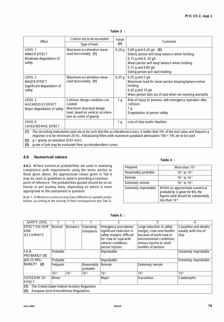
Pt F, Ch 2, App 1
Table 3 :
4.6 Numerical values
4.6.1 Where numerical probabilities are used in assessingcompliance with requirements using the terms similar tothose given above, the approximate values given in Tab 4may be used as guidelines to assist in providing a commonpoint of reference. The probabilities quoted should be on anhourly or per journey basis, depending on which is moreappropriate to the assessment in question.
Note 1: Different occurrences may have different acceptable proba-bilities, according to the severity of their consequences (see Tab 5).
Table 4 :
Table 5 :
EffectCriteria not to be exceeded Value
(2) CommentType of load
LEVEL 1MINOR EFFECTModerate degradation of safety
Maximum acceleration meas-ured horizontally (1)
0,20 g 0,08 g and 0,20 g/s (3)Elderly person will keep balance when holding0,15 g and 0, 20 g/sMean person will keep balance when holding0,15 g and 0,80 g/sSitting person will start holding
LEVEL 2MAJOR EFFECTSignificant degradation of safety
Maximum acceleration meas-ured horizontally (1)
0,35 g 0,25 g and 2 g/sMaximum load for mean person keeping balance when holding0,45 g and 10 g/sMean person fails out of seat when nor wearing seat belts
LEVEL 3HAZARDOUS EFFECTMajor degradation of safety
Collision design condition cal-culatedMaximum structural design load, based on vertical accelera-tion at centre of gravity
1 g Risk of injury to persons, safe emergency operation after collision1 gDegradation of person safety
LEVEL 4CATASTROPHIC EFFECT
1 g Loss of ship and/or fatalities
(1) The recording instruments used are to be such that the accelerationaccuracy is better than 5% of the real value and frequency response is to be minimum 20 Hz. Antialiasing filters with maximum passband attenuation 100 + 5% are to be used
(2) g = gravity acceleration (9,81 m/s2)(3) g-rate of jerk may be evaluated from acceleration/time curves
Frequent More than 10-3
Reasonably probable 10-3 to 10-5
Remote 10-5 to 10-7
Extremely remote 10-7 to 10-9
Extremely improbable Whilst no approximate numerical probability is given for this, thefigures used should be substantially less than 10-9
SAFETY LEVEL 1 1 1 2 3 4EFFECT ON SHIP ANDOCCUPANTS
Normal Nuisance Operatinglimitations
Emergency procedures; significant reduction in safety margins; difficult for crew to cope with adverse conditions; person injuries
Large reduction in safety margin; crew over-burden because of work-load or environmental conditions; serious injuries to small number of persons
Casualties and deaths, usually with loss of ship
F.A.R. PROBABILIT (1)
Probable Improbable Extremely improbable
JAR-25 PRO-BABILITY (2)
Probable Improbable Extremely improbableFrequent Reasonably
probableRemote Extremely remote
10-0 10-2 10-3 10-5 10-7 10-9
CATEGORY OF EFFECT
Minor Major Hazardous Catastrophic
(1) The United States Federal Aviation Regulation(2) European Joint Airworthiness Regulations
June 2003 BVmili 75

Pt F, Ch 2, App 1
76
BVmili June 2003
Part FAdditional Class Notations
Chapter 3
AUTOMATION SYSTEMS (AUT)
SECTION 1 UNATTENDED MACHINERY SPACES (AUT-UMS)
SECTION 2 CENTRALISED CONTROL STATION (AUT-CCS)
SECTION 3 AUTOMATED OPERATION IN PORT (AUT-PORT)
SECTION 4 INTEGRATED MACHINERY SPACES (AUT-IMS)
June 2003 BVmili 77

78 BVmili June 2003
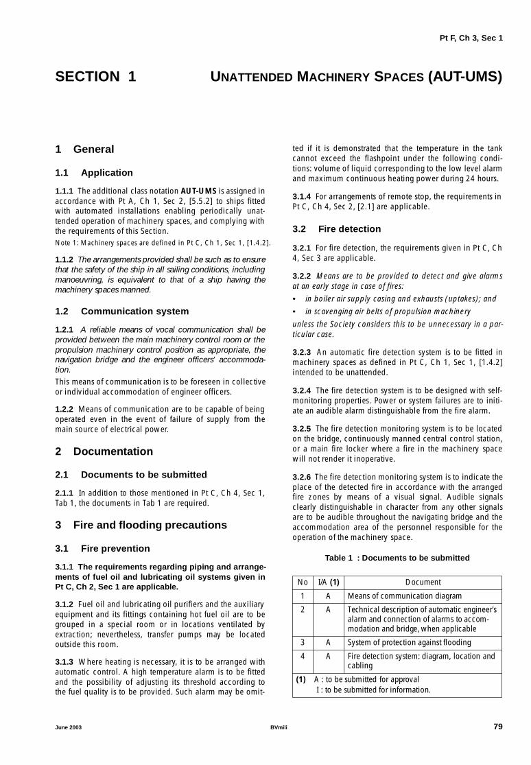
Pt F, Ch 3, Sec 1
SECTION 1 UNATTENDED MACHINERY SPACES (AUT-UMS)
1 General
1.1 Application
1.1.1 The additional class notation AUT-UMS is assigned inaccordance with Pt A, Ch 1, Sec 2, [5.5.2] to ships fittedwith automated installations enabling periodically unat-tended operation of machinery spaces, and complying withthe requirements of this Section.Note 1: Machinery spaces are defined in Pt C, Ch 1, Sec 1, [1.4.2].
1.1.2 The arrangements provided shall be such as to ensurethat the safety of the ship in all sailing conditions, includingmanoeuvring, is equivalent to that of a ship having themachinery spaces manned.
1.2 Communication system
1.2.1 A reliable means of vocal communication shall beprovided between the main machinery control room or thepropulsion machinery control position as appropriate, thenavigation bridge and the engineer officers’ accommoda-tion.This means of communication is to be foreseen in collectiveor individual accommodation of engineer officers.
1.2.2 Means of communication are to be capable of beingoperated even in the event of failure of supply from themain source of electrical power.
2 Documentation
2.1 Documents to be submitted
2.1.1 In addition to those mentioned in Pt C, Ch 4, Sec 1,Tab 1, the documents in Tab 1 are required.
3 Fire and flooding precautions
3.1 Fire prevention
3.1.1 The requirements regarding piping and arrange-ments of fuel oil and lubricating oil systems given inPt C, Ch 2, Sec 1 are applicable.
3.1.2 Fuel oil and lubricating oil purifiers and the auxiliaryequipment and its fittings containing hot fuel oil are to begrouped in a special room or in locations ventilated byextraction; nevertheless, transfer pumps may be locatedoutside this room.
3.1.3 Where heating is necessary, it is to be arranged withautomatic control. A high temperature alarm is to be fittedand the possibility of adjusting its threshold according tothe fuel quality is to be provided. Such alarm may be omit-
ted if it is demonstrated that the temperature in the tankcannot exceed the flashpoint under the following condi-tions: volume of liquid corresponding to the low level alarmand maximum continuous heating power during 24 hours.
3.1.4 For arrangements of remote stop, the requirements inPt C, Ch 4, Sec 2, [2.1] are applicable.
3.2 Fire detection
3.2.1 For fire detection, the requirements given in Pt C, Ch4, Sec 3 are applicable.
3.2.2 Means are to be provided to detect and give alarmsat an early stage in case of fires:
• in boiler air supply casing and exhausts (uptakes); and
• in scavenging air belts of propulsion machinery
unless the Society considers this to be unnecessary in a par-ticular case.
3.2.3 An automatic fire detection system is to be fitted inmachinery spaces as defined in Pt C, Ch 1, Sec 1, [1.4.2]intended to be unattended.
3.2.4 The fire detection system is to be designed with self-monitoring properties. Power or system failures are to initi-ate an audible alarm distinguishable from the fire alarm.
3.2.5 The fire detection monitoring system is to be locatedon the bridge, continuously manned central control station,or a main fire locker where a fire in the machinery spacewill not render it inoperative.
3.2.6 The fire detection monitoring system is to indicate theplace of the detected fire in accordance with the arrangedfire zones by means of a visual signal. Audible signalsclearly distinguishable in character from any other signalsare to be audible throughout the navigating bridge and theaccommodation area of the personnel responsible for theoperation of the machinery space.
Table 1 : Documents to be submitted
No I/A (1) Document
1 A Means of communication diagram
2 A Technical description of automatic engineer’s alarm and connection of alarms to accom-modation and bridge, when applicable
3 A System of protection against flooding
4 A Fire detection system: diagram, location and cabling
(1) A : to be submitted for approval I : to be submitted for information.
June 2003 BVmili 79

Pt F, Ch 3, Sec 1
3.2.7 Fire detectors are to be of such type and so locatedthat they will rapidly detect the onset of fire in conditionsnormally present in the machinery space. Consideration isto be given to avoiding false alarms. The type and locationof detectors are to be approved by the Society and a combi-nation of detector types is recommended in order to enablethe system to react to more than one type of fire symptom.
3.2.8 Except in spaces of restricted height and where theiruse is specially appropriate, detection systems using ther-mal detectors only are not permitted. Flame detectors maybe installed, although they are to be considered as comple-mentary and are not to replace the main installation.
3.2.9 Fire detector zones are to be arranged in a mannerthat will enable the operating staff to locate the seat of thefire. The arrangement and the number of loops and thelocation of detector heads are to be approved in each case.Air currents created by the machinery are not to render thedetection system ineffective.
3.2.10 When fire detectors are provided with the means toadjust their sensitivity, necessary arrangements are to beallowed to fix and identify the set point.
3.2.11 When it is intended that a particular loop or detec-tor is to be temporarily switched off, this state is to beclearly indicated. Reactivation of the loop or detector is tobe performed automatically after a preset time.
3.2.12 The fire detection monitoring system is to be pro-vided with facilities for functional testing.
3.2.13 The fire detecting system is to be fed automaticallyfrom the emergency source of power by a separate feeder ifthe main source of power fails.
3.2.14 Facilities are to be provided in the fire detecting sys-tem to manually release the fire alarm from the followingplaces:
• passageways having entrances to engine and boilerrooms
• the navigating bridge
• the continuously manned central control station
• the control station in the engine room.
3.3 Fire fighting
3.3.1 Unless otherwise stated, pressurisation of the firemain at a suitable pressure by starting a main fire pump andcarrying out the other necessary operations is to be possiblefrom the bridge and the continuously manned central con-trol station. Alternatively, the fire main system may be per-manently under pressure.
3.3.2 In addition to the fire-extinguishing arrangementsmentioned in Part C, Chapter 5, periodically unattendedspaces containing steam turbines (whose power is at least375 kW) are to be provided with one of the fixed fire-extin-guishing systems required in the same Chapter for machin-ery spaces of category A containing oil fired boilers or fueloil units.
3.4 Protection against flooding
3.4.1 Bilge wells or machinery spaces bilge levels are to bemonitored in such a way that the accumulation of liquid isdetected in normal angles of trim and heel.
3.4.2 Where the bilge pumps are capable of being startedautomatically, means shall be provided to indicate when theinflux of liquid is greater than the pump capacity or whenthe pump is operating more frequently than would normallybe expected.
3.4.3 All automatic bilge system can be stopped in ease ofsilent operation. A selector switch will be fitted in theengine control console with a silent position to suppress allthese automatic functions. An alarm in the wheelhouse willbe initiated to confirm the silent operation.
3.4.4 The location of controls of any valve serving a seainlet, a discharge below the waterline or a bilge injectionsystem shall be so sited as to allow adequate time for opera-tion in case of influx of water to the space, having regard tothe time likely to be required in order to reach and operatesuch controls. If the level to which the space could becomeflooded with the ship in the fully loaded condition sorequires, arrangements shall be made to operate the con-trols from a position above such level.
3.4.5 Bilge level alarms are to be given at the main controlstation, the bridge and the continuously manned centralcontrol station.
3.4.6 Alarm is to be given to the navigating bridge and atthe continuously manned central control station in case offlooding into the machinery space situated below the loadline.
3.4.7 The control devices of any sea water valve, a dis-charge below the waterline or a bilge well ejector are to belocated in such a way that the operator gets time enough forshutting the closing device in case of room flooding, takingaccount of the time needed to reach and operate these con-trol devices. For the justifying calculation, it is necessary totake into consideration the flooding level which can bereached when the ship is fully loaded and, if necessary, aremote control device is to be fitted above this level.
4 Control of machinery
4.1 General
4.1.1 Under all sailing conditions, including manoeuvring,the speed, direction of thrust and, if applicable, the pitch ofthe propeller shall be fully controllable from the navigationbridge.
4.1.2 All manual operations or services expected to be car-ried out with a periodicity of less than 24 h are to be elimi-nated or automated, particularly for: lubrication, topping upof make up tanks and filling tanks, filter cleaning, cleaningof centrifugal purifiers, drainage, load sharing on mainengines and various adjustments. Nevertheless, the transferof operation mode may be effected manually.
80 BVmili June 2003

Pt F, Ch 3, Sec 1
4.1.3 A centralised control position shall be arranged withthe necessary alarm panels and instrumentation indicatingany alarm.
4.1.4 Parameters for essential services which need to beadjusted to a preset value are to be automatically control-led.
4.1.5 The control system shall be such that the servicesneeded for the operation of the main propulsion machineryand its auxiliaries are ensured through the necessary auto-matic arrangements.
4.1.6 It shall be possible for all machinery essential for thesafe operation of the ship to be controlled from a local posi-tion, even in the case of failure in any part of remote controlsystems.
4.1.7 The design of the remote automatic control systemshall be such that in the case of its failure an alarm will begiven. Unless impracticable, the preset speed and directionof thrust of the propeller shall be maintained until local con-trol is in operation.
4.1.8 Critical speed ranges, if any, are to be rapidly passedover by means of an appropriate device.
4.1.9 Propulsion machinery is to stop automatically only inexceptional circumstances which could cause quick criticaldamage, due to internal faults in the machinery. The designof automation systems whose failure could result in anunexpected propulsion stop is to be specially examined. Anoverriding device for cancelling the automatic shutdown isto be considered.
4.1.10 Where the propulsive plant includes several mainengines, a device is to be provided to prevent any abnormaloverload on each of them.
4.1.11 Where standby machines are required for other aux-iliary machinery essential to propulsion, automatic change-over devices shall be provided.
4.2 Diesel propulsion plants
4.2.1 When a diesel engine is used for the propulsionplant, monitoring and control of equipment is to be per-formed according to Tab 2 for medium or high speedengines.
4.3 Gas turbine propulsion plants
4.3.1 For gas turbines, monitoring and control elements arerequired according to Tab 3.
4.4 Electrical propulsion plant
4.4.1 Documents to be submitted
The following additional documents are to be submitted tothe Society:
• A list of the alarms and shutdowns of the electrical pro-pulsion system
• When the control and monitoring system of the propul-sion plant is computer based, a functional diagram ofthe interface between the programmable logic control-ler and computer network.
4.4.2 Alarm system
The following requirements are applicable to the alarm sys-tem of electrical propulsion:
• Alarms circuits of electrical propulsion are to be con-nected to the main alarm system on board. As an alter-native, the relevant circuit may be connected to a localalarm unit. In any case, a connection between the localalarm unit and the main alarm system is to be provided.
• The alarms can be arranged in groups, and shown in thecontrol station. This is acceptable when a discriminationis possible locally.
• When the control system uses a computer based system,the requirements of Pt C, Ch 4, Sec 3 are applicable, inparticular, for the data transmission link between thealarm system and the control system.
• Individual alarms are considered as critical and are tobe individually activated at the control stations, andacknowledged individually.
• Shutdown activation is to be considered as an individ-ual alarm.
4.4.3 Safety functions
The following requirements are applicable to the safety sys-tem of electrical propulsion:
• As a general rule, safety stop using external sensors suchas temperature, pressure overspeed, main cooling fail-ure, stop of converter running by blocking impulse is tobe confirmed by the automatic opening of the main cir-cuit using a separate circuit.
• In order to avoid accidental stop of the propulsion lineand limit the risk of blackout due to wire break, the trip-ping of the main circuit-breaker is to be activated by anemission coil with a monitoring of the line wire break.
• In the case of a single line propulsion system, the powerlimitation order is to be duplicated.
• As a general rule, when the safety stop is activated, it isto be maintained until local acknowledgement.
4.4.4 Transformers
For transformers, parameters according to Tab 4 are to becontrolled or monitored.
4.4.5 Converters
For converters, parameters according to Tab 5, Tab 6 andTab 7 are to be monitored or controlled.
4.4.6 Smoothing coil
For the converter reactor, parameters according to Tab 8 areto be monitored or controlled.
June 2003 BVmili 81

Pt F, Ch 3, Sec 1
Table 2 : Main propulsion medium or high speed diesel engine
Symbol conventionH = High, HH = High high, G = group alarmL = Low, LL = Low low, I = individual alarmX = function is required, R = remote
Monitoring
Automatic control
Main Engine Auxiliary
Identification of system parameter Alarm Indic Slow-down
Shut-down
Control Standby Start
Stop
Fuel oil system
• Fuel oil pressure after filter (engine inlet) L R
X
• Fuel oil viscosity before injection pumps or fuel oil temperature before injection pumps (for engine run-ning on heavy fuel)
H + L
X
• Leakage from high pressure pipes where required H
Lubricating oil system
• Lubricating oil to main bearing and thrust bearing pressure
L R
X X
LL X
• Lubricating oil filter differential pressure H R
• Lubricating oil inlet temperature H R
X
• Oil mist concentration in crankcase (1) H X
• Flow rate cylinder lubricator (each apparatus) L X
• Lubricating oil to turbocharger inlet pressure (2) L R
Sea water cooling system
• Sea water cooling pressure L R
X
Cylinder fresh cooling water system
• Cylinder water inlet pressure or flow L R X
X
• Cylinder water outlet temperature H R
X
• Level of cylinder cooling water in expansion tank L
Scavenge air system
• Scavenging air receiver temperature H
Exhaust gas system
• Exhaust gas temperature after each cylinder (3) H R X
• Exhaust gas temperature after each cylinder (3), devi-ation from average
H
Miscellaneous
• Engine speed R
X
• Engine overspeed H X
• Control, safety, alarm system power supply failure X
(1) Only for medium speed engines having a power of more than 2250 kw or a cylinder bore of more than 300 mm. One oil mist detector for each engine having two independent outputs for initiating the alarm and shutdown would satisfy the requirement for independence between alarm and shutdown system.
(2) If without integrated self-contained oil lubrication system.(3) For engine power > 500 kW/cyl.
82 BVmili June 2003

Pt F, Ch 3, Sec 1
4.4.7 Propulsion electric motorFor propulsion electric motors, parameters according to Tab9 are to be monitored or controlled.
4.4.8 All parameters listed in the tables of this item are con-sidered as a minimum requirement for unattended machin-ery spaces.Some group alarms may be locally detailed on the corre-sponding unit (for instance loss of electronic supply, failureof electronic control unit, etc.)
4.5 Shafting, clutches, CPP, gears
4.5.1 For shafting and clutches, parameters according toTab 10 are to be monitored or controlled.
4.5.2 For controllable pitch propellers, parameters accord-ing to Tab 11 are to be monitored or controlled.
4.5.3 For reduction gears and reversing gears, parametersaccording to Tab 12 are to be monitored or controlled.
Table 3 : Propulsion gas turbine
Symbol conventionH = High, HH = High high, G = group alarmL = Low, LL = Low low, I = individual alarmX = function is required, R = remote
Monitoring
Automatic control
Turbine Auxiliary
Identification of system parameter Alarm Indic Slow-down
Shut-down
Control Standby Start
Stop
Lubricating oil system
• Turbine supply pressure L X X
LL X
• Differential pressure across lubricating oil filter H
• Bearing or lubricating oil (discharge) temperature H
Mechanical monitoring of gas turbine
• Speed R X
H X
• Vibration H
HH X
• Rotor axial displacement (not applicable to roller bear-ing)
H
HH X
• Number of cycles performed by rotating parts H
Gas generator monitoring system
• Flame and ignition failure X
• Fuel oil supply pressure L
• Fuel oil supply temperature H + L
X
• Cooling medium temperature H
• Exhaust gas temperature or gas temperature in specific locations of flow gas path (alarm before shutdown)
H
HH X
• Pressure at compressor inlet (alarm before shutdown) L
Miscellaneous
• Control system failure X
• Automatic starting failure X
June 2003 BVmili 83

Pt F, Ch 3, Sec 1
Table 4 : Transformers
Table 5 : Network converter
Symbol conventionH = High, HH = High high, G = group alarmL = Low, LL = Low low, I = individual alarmX = function is required, R = remote
Monitoring
Automatic control
Motor Auxiliary
Identification of system parameter Alarm Indic Slow-down
Shut-down
Control Standby Start
Stop
Earth failure on main propulsion circuits I
Circuit-breaker, short-circuit I (2) X
Circuit-breaker, overload I (2) X
Circuit-breaker, undervoltage I (2) X
Temperature of winding on phase 1, 2, 3 (1) G
I, H X (3)
I, HH X
Temperature sensor failure (short-circuit, open circuit, supply failure)
G
Cooling pump pressure or flow G, L
X
X
Cooling medium temperature G, H X
Leak of cooling medium G
X
(1) A minimum of 6 temperature sensors are to be provided : • 3 temperature sensors to be connected to the alarm system (can also be used for the redundant tripping of the main circuit-
breaker)• 3 temperature sensors connected to the control unit.
(2) To be kept in the memory until local acknowledgement.(3) Possible override of slowdown by the operator.
Symbol conventionH = High, HH = High high, G = group alarmL = Low, LL = Low low, I = individual alarmX = function is required, R = remote
Monitoring
Automatic control
Motor Auxiliary
Identification of system parameter Alarm Indic Slow-down
Shut-down
Control Standby Start
Stop
Short-circuit current I max I X
Overvoltage G X
Undervoltage G
Phase unbalanced I (X) (1)
Power limitation failure I
Protection of filter circuit trip I
Circuit-breaker opening operation failure I
Communication circuit, control circuits, power supplies, watchdog of control system according to supplier’s design
G X
(1) This parameter, when indicated in brackets, is only advisable according to the supplier’s requirements.
84 BVmili June 2003

Pt F, Ch 3, Sec 1
Table 6 : Motor converter
Table 7 : Converter cooling circuit
Table 8 : Smoothing coil
Symbol conventionH = High, HH = High high, G = group alarmL = Low, LL = Low low, I = individual alarmX = function is required, R = remote
Monitoring
Automatic control
Motor Auxiliary
Identification of system parameter Alarm IndicSlow-down
Shut-down
Control Standby Start
Stop
Short-circuit current I max I X
Overvoltage G X
Undervoltage G X
Phase unbalanced I
Protection of filter circuit trip I
Communication circuit, control circuits, power supplies, watchdog of control system according to supplier’s design
G X
Speed sensor system failure G X (1)Overspeed I X
(1) Automatic switch-over to the redundant speed sensor system.
Symbol conventionH = High, HH = High high, G = group alarmL = Low, LL = Low low, I = individual alarmX = function is required, R = remote
Monitoring
Automatic control
Motor Auxiliary
Identification of system parameter Alarm IndicSlow-down
Shut-down
Control Standby Start
Stop
Air cooling temperature high I R
Ventilation, fan failure G
X
Cooling pump pressure or flow low G R
X
Cooling fluid temperature high G
Leak of cooling medium G
X
Temperature sensor failure (short-circuit, open circuit, supply failure)
G
Symbol conventionH = High, HH = High high, G = group alarmL = Low, LL = Low low, I = individual alarmX = function is required, R = remote
Monitoring
Automatic control
Motor Auxiliary
Identification of system parameter Alarm IndicSlow-down
Shut-down
Control Standby Start
Stop
Temperature of coil I, H R
I, HH
Air cooling temperature I, H
Ventilation fan failure G
X
Cooling pump pressure or flow low G R
X
Cooling fluid temperature high G
Leak of cooling medium G
X
Temperature sensor failure (short-circuit, open circuit, supply failure)
G
June 2003 BVmili 85
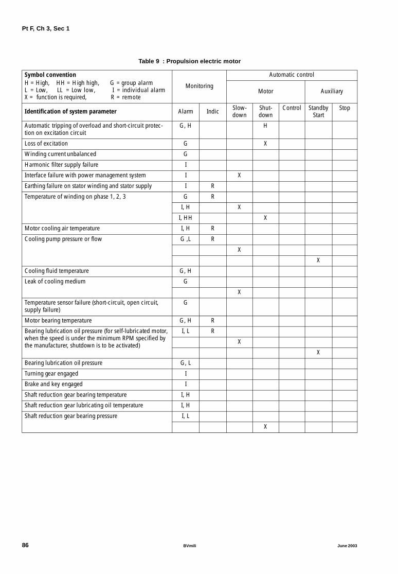
Pt F, Ch 3, Sec 1
Table 9 : Propulsion electric motor
Symbol conventionH = High, HH = High high, G = group alarmL = Low, LL = Low low, I = individual alarmX = function is required, R = remote
Monitoring
Automatic control
Motor Auxiliary
Identification of system parameter Alarm Indic Slow-down
Shut-down
Control Standby Start
Stop
Automatic tripping of overload and short-circuit protec-tion on excitation circuit
G, H H
Loss of excitation G X
Winding current unbalanced G
Harmonic filter supply failure I
Interface failure with power management system I X
Earthing failure on stator winding and stator supply I R
Temperature of winding on phase 1, 2, 3 G R
I, H X
I, HH X
Motor cooling air temperature I, H R
Cooling pump pressure or flow G ,L R
X
X
Cooling fluid temperature G, H
Leak of cooling medium G
X
Temperature sensor failure (short-circuit, open circuit, supply failure)
G
Motor bearing temperature G, H R
Bearing lubrication oil pressure (for self-lubricated motor, when the speed is under the minimum RPM specified by the manufacturer, shutdown is to be activated)
I, L R
X
X
Bearing lubrication oil pressure G, L
Turning gear engaged I
Brake and key engaged I
Shaft reduction gear bearing temperature I, H
Shaft reduction gear lubricating oil temperature I, H
Shaft reduction gear bearing pressure I, L
X
86 BVmili June 2003

Pt F, Ch 3, Sec 1
Table 10 : Shafting and clutches of propulsion machinery
Table 11 : Controllable pitch propeller
Table 12 : Reduction gears/reversing gears
4.6 Auxiliary system
4.6.1 Where standby machines are required for other auxil-iary machinery essential to propulsion, automatic change-over devices shall be provided.Change-over restart is to be provided for the following sys-tems:• cylinder, piston and fuel valve cooling • cylinder cooling of diesel generating sets (where the cir-
cuit is common to several sets)• main engine fuel supply• diesel generating sets fuel supply (where the circuit is
common to several sets) • sea water cooling for propulsion plant • sea water to main condenser (main turbines)• hydraulic control of clutch, CPP or main thrust unit
• thermal fluid systems (thermal fluid heaters).
4.6.2 When a standby machine is automatically started, analarm is to be activated.
4.6.3 When the propulsion plant is divided into two ormore separate units, the automatic standby auxiliary may beomitted, when the sub-units concerned are fully separatedwith regard to power supply, cooling system, lubricatingsystem etc.Some of the propulsive plants may be partially used for rea-sons of economy (use of one shaft line or one propulsionengine for instance). If so, automatic change-over, neces-sary for this exploitation mode, is to be provided.
4.6.4 Means shall be provided to keep the starting air pres-sure at the required level where internal combustionengines are used for main propulsion.
Symbol conventionH = High, HH = High high, G = group alarmL = Low, LL = Low low, I = individual alarmX = function is required, R = remote
Monitoring
Automatic control
Main Engine Auxiliary
Identification of system parameter Alarm Indic Slow-down
Shut-down
Control Standby Start
Stop
Temperature of each shaft thrust bearing (not applicable for ball or roller bearings)
H X
Sterntube bush oil gravity tank level L
Clutch lubricating oil temperature H X
Clutch oil tank level L
Symbol conventionH = High, HH = High high, G = group alarmL = Low, LL = Low low, I = individual alarmX = function is required, R = remote
Monitoring
Automatic control
Main Engine Auxiliary
Identification of system parameter Alarm Indic Slow-down
Shut-down
Control Standby Start
Stop
Control oil temperature before cooler H
Oil tank level L
Symbol conventionH = High, HH = High high, G = group alarmL = Low, LL = Low low, I = individual alarmX = function is required, R = remote
Monitoring
Automatic control
Main Engine Auxiliary
Identification of system parameter Alarm Indic Slow-down
Shut-down
Control Standby Start
Stop
Lubricating oil temperature at the oil cooler outlet H R (1) X
Lubricating oil pressure L (1) R X
X
Oil tank level L R X
LL X
(1) May be omitted in the case of restricted navigation notation.
June 2003 BVmili 87

Pt F, Ch 3, Sec 1
4.6.5 Where daily service fuel oil tanks are filled automati-cally, or by remote control, means shall be provided to pre-vent overflow spillages.
4.6.6 Arrangements are to be provided to prevent overflowspillages coming from equipment treating flammable liq-uids.
4.6.7 Where daily service fuel oil tanks or settling tanks arefitted with heating arrangements, a high temperature alarmshall be provided if the flashpoint of the fuel oil can beexceeded.
4.6.8 For auxiliary systems, the following parameters,according to Tab 13 to Tab 23 are to be monitored or con-trolled.
Table 13 : Control and monitoring of auxiliary electrical systems
Table 14 : Incinerators
Table 15 : Auxiliary boilers
Symbol conventionH = High, HH = High high, G = group alarmL = Low, LL = Low low, I = individual alarmX = function is required, R = remote
Monitoring
Automatic control
Main Engine Auxiliary
Identification of system parameter Alarm Indic Slow-down
Shut-down
Control Standby Start
Stop
Electric circuit, blackout X
Power supply failure of control, alarm and safety system X
Symbol conventionH = High, HH = High high, G = group alarmL = Low, LL = Low low, I = individual alarmX = function is required, R = remote
Monitoring
Automatic control
Incinerator Auxiliary
Identification of system parameter Alarm Indic Slow-down
Shut-down
Control Standby Start
Stop
Combustion air pressure L X
Flame failure X X
Furnace temperature H X
Exhaust gas temperature H
Fuel oil pressure L
Fuel oil temperature or viscosity , where heavy fuel is used H + L
Symbol conventionH = High, HH = High high, G = group alarmL = Low, LL = Low low, I = individual alarmX = function is required, R = remote
Monitoring
Automatic control
Boiler Auxiliary
Identification of system parameter Alarm Indic Slow-down
Shut-down
Control Standby Start
Stop
Water level L + H X X
Fuel oil temperature L + H X X
Flame failure X
X
Combustion air supply fan low pressure X
Temperature in boiler casing (fire) H
Steam pressure H (1) X X
Steam temperature X (2)
(1) When the automatic control does not cover the entire load range from zero load.(2) For superheated steam over 330°C.
88 BVmili June 2003

Pt F, Ch 3, Sec 1
Table 16 : Fuel oil system
Table 17 : Lubricating oil system
Symbol conventionH = High, HH = High high, G = group alarmL = Low, LL = Low low, I = individual alarmX = function is required, R = remote
Monitoring
Automatic control
System Auxiliary
Identification of system parameter Alarm Indic Slow-down
Shut-down
Control Standby Start
Stop
Fuel oil tank level, overflow H (1)
Air pipe water trap level on fuel oil tanks H (2)
Heater outlet fuel oil temperature H (4) X (5) X
Sludge tank level H
Fuel oil settling tank level H (1)
Fuel oil settling tank temperature H (3)
Fuel oil centrifugal purifier overflow H X
Fuel oil in daily service tank level L
Fuel oil daily service tank temperature H (3) X
Fuel oil in daily service tank level(to be provided if no suitable overflow arrangement)
H (1)
(1) Or sight-glasses on the overflow pipe.(2) Or alternative arrangement as per Pt C, Ch 2, Sec 1, [9.1.7].(3) Applicable where heating arrangements are provided.(4) Or low flow alarm in addition to temperature control when heated by steam or other media.(5) Cut off of electrical power supply when electrically heated.
Symbol conventionH = High, HH = High high, G = group alarmL = Low, LL = Low low, I = individual alarmX = function is required, R = remote
Monitoring
Automatic control
System Auxiliary
Identification of system parameter Alarm Indic Slow-down
Shut-down
Control Standby Start
Stop
Air pipe water trap level of lubricating oil tankSee Pt C, Ch 2, Sec 1, [9.1.7]
H
Sludge tank level H
Lubricating oil centrifugal purifier overflow(stop of oil supply)
H
X
June 2003 BVmili 89

Pt F, Ch 3, Sec 1
Table 18 : Thermal oil system
Table 19 : Hydraulic oil system
Table 20 : Boiler feed and condensate system
Symbol conventionH = High, HH = High high, G = group alarmL = Low, LL = Low low, I = individual alarmX = function is required, R = remote
Monitoring
Automatic control
System Auxiliary
Identification of system parameter Alarm Indic Slow-down
Shut-down
Control Standby Start
Stop
Forced draft fan stopped X
Thermal fluid temperature H
X
Thermal fluid pressure X
Flow through each element L X
Heavy fuel oil temperature or viscosity H + L X
Burner flame failure X X
Flue gas temperature (when exhaust gas heater) H X
Expansion tank level L X (1)
(1) Stop of burner and fluid flow.
Symbol conventionH = High, HH = High high,L = Low, LL = Low low,X = function is required,
G = group alarm I = individual alarmR = remote (AUT-CCS only)
Monitoring
Automatic control
System Auxiliary
Identification of system parameter Alarm Indic Slow-down
Shut-down
Control Standby Start
Stop
Pump pressure L + H
Service tank level L (1)
(1) The low level alarm is to be activated before the quantity of lost oil reaches 100 litres or 50% of the circuit volume , whichever is the lesser.
Symbol conventionH = High, HH = High high,L = Low, LL = Low low,X = function is required,
G = group alarm I = individual alarmR = remote (AUT-CCS only)
Monitoring
Automatic control
System Auxiliary
Identification of system parameter Alarm Indic Slow-down
Shut-down
Control Standby Start
Stop
Sea water flow or equivalent L X
Vacuum L
LL X
Water level in main condenser (unless justified) H + L
X
HH X
Salinity of condensate H
Feed water pump delivery pressure L X
Feed water tank level L
Deaerator inside temperature or pressure L + H (1)
Water level in deaerator L + H
Extraction pump pressure L
Drain tank level L + H
(1) In the case of forced circulation boiler.
90 BVmili June 2003

Pt F, Ch 3, Sec 1
Table 21 : Compressed air system
Table 22 : Cooling system
Table 23 : Thrusters
Symbol conventionH = High, HH = High high,L = Low, LL = Low low,X = function is required,
G = group alarm I = individual alarmR = remote (AUT-CCS only)
Monitoring
Automatic control
System Auxiliary
Identification of system parameter Alarm Indic Slow-down
Shut-down
Control Standby Start
Stop
Air temperature at compressor outlet H
Compressor lubricating oil pressure (except where splash lubrication)
LL X
Control air pressure (3) L R
X
Starting air pressure before main shut-off valve L (2) local + R (1)
X
X X
Safety air pressure (3) L
X
(1) Remote indication is required if starting of air compressor is remote controlled, from wheelhouse for example.(2) For starting air, the alarm minimum pressure set point is to be so adjusted as to enable at least four starts for reversible propulsion
engines and two starts for non-reversible propulsion engines. (3) When supplied through reducing valve, see Pt C, Ch 2, Sec 1, [2.4.4].
Symbol conventionH = High, HH = High high, G = group alarmL = Low, LL = Low low, I = individual alarmX = function is required, R = remote
Monitoring
Automatic control
System Auxiliary
Identification of system parameter Alarm Indic Slow-down
Shut-down
Control Standby Start
Stop
Sea water pump pressure or flow X X
L
Fresh water pump pressure or flow X X
L
Level in cooling water expansion tank L
Symbol conventionH = High, HH = High high, G = group alarmL = Low, LL = Low low, I = individual alarmX = function is required, R = remote
Monitoring
Automatic control
Thruster Auxiliary
Identification of system parameter Alarm Indic Slow-down
Shut-down
Control Standby Start
Stop
Control oil temperature (preferably before cooler) H
Oil tank level L
June 2003 BVmili 91

Pt F, Ch 3, Sec 1
4.7 Control of electrical installation
4.7.1 Where the electrical power can normally be suppliedby one generator, suitable load shedding arrangement shallbe provided to ensure the integrity of supplies to servicesrequired for propulsion and steering as well as the safety ofthe ship.
4.7.2 In the case of loss of the generator in operation, ade-quate provision shall be made for automatic starting andconnecting to the main switchboard of a standby generatorof sufficient capacity to permit propulsion and steering andto ensure the safety of the ship with automatic restarting ofthe essential auxiliaries including, where necessary, sequen-tial operations.
4.7.3 The standby electric power is to be available in notmore than 45 seconds.
4.7.4 If the electrical power is normally supplied by morethan one generator simultaneously in parallel operation,provision shall be made, for instance by load shedding, to
ensure that, in the case of loss of one of these generatingsets, the remaining ones are kept in operation without over-load to permit propulsion and steering, and to ensure thesafety of the ship.
4.7.5 Following a blackout, automatic connection of thestandby generating set is to be followed by an automaticrestart of the essential electrical services. If necessary, timedelay sequential steps are to be provided to allow satisfac-tory operation.
4.7.6 Monitored parameters for which alarms are requiredto identify machinery faults and associated safeguards arelisted in Tab 24 and Tab 25. These alarms are to be indi-cated at the control location for machinery as individualalarms; where the alarm panel with all individual alarms isinstalled on the engine or in the vicinity, a common alarmin the control location for machinery is required. For com-munication of alarms from the machinery space to thebridge area and accommodation for engineering personnel,detailed requirements are contained in [5].
Table 24 : Auxiliary reciprocating I.C. engines driving generators
Symbol conventionH = High, HH = High high, G = group alarmL = Low, LL = Low low, I = individual alarmX = function is required, R = remote
Monitoring
Automatic control
Engine Auxiliary
Identification of system parameter Alarm Indic Slow-down
Shut-down
Control Standby Start
Stop
Fuel oil viscosity or temperature before injection L + H local
X
Fuel oil pressure local
Fuel oil leakage from pressure pipes H
Lubricating oil temperature H
Lubricating oil pressure3 L local X
LL X (1)
Oil mist concentration in crankcase (2) H X
Pressure or flow of cooling water, if not connected to main system
L local
Temperature of cooling water or cooling air H local
Level in cooling water expansion tank, if not connected to main system
L
Engine speed local
X
H X
Fault in the electronic governor system X
(1) Not applicable to emergency generator set.(2) For engines having a power of more than 2250 kw or a cylinder bore of more than 300 mm.
92 BVmili June 2003

Pt F, Ch 3, Sec 1
Table 25 : Auxiliary steam turbines
5 Alarm system
5.1 General
5.1.1 A system of alarm displays and controls is to be pro-vided which readily allows identification of faults in themachinery and satisfactory supervision of related equip-ment. This may be arranged at a main control station or,alternatively, at subsidiary control stations. In the latter case,a master alarm display is to be provided at the main controlstation showing which of the subsidiary control stations isindicating a fault condition.
5.1.2 Unless otherwise justified, separation of monitoringand control systems is to be provided.
5.1.3 The alarm system is to be designed to function inde-pendently of control and safety systems, so that a failure ormalfunction of these systems will not to prevent the alarmsystem from operating. Common sensors for alarms andautomatic slowdown functions are acceptable as specifiedin each specific table.The independence is not required if the controlled machin-ery is duplicated and if the control and safety of duplicatedmachinery is achieved by an other independent system.This is also to be analysed with the fire risk of the machin-ery.
5.1.4 The alarm system shall be continuously powered andshall have an automatic change-over to a standby powersupply in the case of loss of normal power supply.
5.2 Alarm system design
5.2.1 The alarm system and associated sensors are to becapable of being tested during normal machinery operation.
5.2.2 Insulation faults on any circuit of the alarm systemare to generate an alarm, when an insulated earth distribu-tion system is used.
5.2.3 An engineers’ alarm is to be activated when themachinery alarm has not been accepted in the machineryspaces or control room within 5 minutes.
5.2.4 The alarm system is to have a connection to the engi-neers’ public rooms and to each of the engineers’ cabins
through a selector switch, to ensure connection to at leastone of those cabins.
5.3 Machinery alarm system
5.3.1 The local silencing of the alarms on the bridge or inaccommodation spaces is not to stop the audible machineryspace alarm.
5.3.2 Machinery faults are to be indicated at the controllocations for machinery.
5.4 Alarm system on navigating bridge
5.4.1 Alarms associated with faults requiring speed reduc-tion or automatic shutdown are to be separately identifiedon the bridge.
5.4.2 The alarm system is to activate an audible and visualalarm on the navigation bridge for any situation whichrequires action by or the attention of the officer on watch.
5.4.3 Individual alarms are to be provided at the navigationbridge indicating any power supply failures of the remotecontrol of propulsion machinery.
6 Safety systems
6.1 General
6.1.1 Safety systems of different units of the machineryplant are to be independent. Failure in the safety system ofone part of the plant is not to interfere with the operation ofthe safety system in another part of the plant, unless themachinery is duplicated.
6.1.2 In order to avoid undesirable interruption in the oper-ation of machinery, the system is to intervene sequentiallyafter the operation of the alarm system by:• starting of standby units• load reduction or shutdown, such that the least drastic
action is taken first.
6.1.3 The arrangement for overriding the shutdown of themain propelling machinery is to be such as to precludeinadvertent operation.
Symbol conventionH = High, HH = High high, G = group alarmL = Low, LL = Low low, I = individual alarmX = function is required, R = remote
Monitoring
Automatic control
Turbine Auxiliary
Identification of system parameter Alarm Indic Slow-down
Shut-down
Control Standby Start
Stop
Turbine speed local
X
HH X
Lubricating oil supply pressure L X
LL X
June 2003 BVmili 93

Pt F, Ch 3, Sec 1
6.1.4 After stoppage of the propulsion engine by a safetyshutdown device, the restart is only to be carried out, unlessotherwise justified, after setting the propulsion bridge con-trol level on «stop».
7 Testing
7.1 General
7.1.1 Tests of automated installations are to be carried outaccording to Pt C, Ch 4, Sec 6 to determine their operatingconditions. The details of these tests are defined, in eachcase, after having studied the concept of the automatedinstallations and their construction. A complete test pro-gram is to be submitted for approval and may be as follows:
7.1.2 The tests of equipment carried out alongside the quayunder normal conditions of use include, for instance:• the electrical power generating set• the auxiliary steam generator• the automatic bilge draining system• automatic centrifugal separators or similar purifying
apparatus• automatic change-over of service auxiliaries• detection of high pressure fuel leaks from diesel gener-
ating sets or from flexible boiler burner pipes.
7.1.3 Sea trials are used to demonstrate the proper opera-tion of the automated machinery and systems. For this pur-pose, for instance, the following tests are to be carried out:• Test of the remote control of propulsion:
- checking of the operation of the automatic controlsystem: programmed or unprogrammed startingspeed increase, reversal, adjusting of the propellerpitch, failure of supply sources, etc.
- checking of the crash astern sequence, to ensure thatthe reversal sequence is properly performed fromfull away, the ship sailing at its normal operation
speed. The purpose of this check is not to control thenautical performances of the ship (such as stoppingdistance, etc.)
- finally, checking of the operation of the whole instal-lation in normal working conditions, i.e. as a gen-eral rule without watch-keeping personnel for themonitoring and/or running of the machinery during6 h at least
- The following procedure may, for instance, be cho-sen: «underway» during 3 h, then decreasing to «fullahead». Staying in that position during 5 min. Thenstopping for 15 min. Then, putting the control leverin the following positions, staying 2 minutes in eachone: astern slow, astern half, astern full, full ahead,half ahead, stop, full astern, stop, ahead dead slow,half ahead, then increasing the power until «under-way» position.
• Test of the operating conditions of the electrical produc-tion :
- automatic starting of the generating set in the eventof a blackout
- automatic restarting of auxiliaries in the event of ablackout
- load-shedding in the event of generating set over-load
- automatic starting of a generating set in the event ofgenerating set overload.
• Test of fire and flooding system:
- Test of normal operation of the fire detection system(detection, system faults)
- Test of detection in the scavenging air belt and boilerair duct
- Test of the fire alarm system
- Test of protection against flooding.
• Test of operating conditions, including manoeuvring, ofthe whole machinery in an unattended situation for 6 h.
94 BVmili June 2003

Pt F, Ch 3, Sec 2
SECTION 2 CENTRALISED CONTROL STATION (AUT-CCS)
1 General
1.1 Application
1.1.1 The additional class notation AUT-CCS is assigned inaccordance with Pt A, Ch 1, Sec 2, [5.5.3] to ships fittedwith a machinery installation operated and monitored froma centralised control station, and complying with therequirements of this Section.
It applies to ships which are intended to be operated withmachinery spaces unattended, but with continuous supervi-sion from a position where control and monitoring devicesof machinery are centralised.
Note 1: Machinery spaces are defined in Pt C, Ch 1, Sec 1, [1.4.2].
1.1.2 Remote indications for continuous supervision of themachinery are to be located in a centralised control posi-tion, to allow a watch service of the machinery space.
1.2 Communication system
1.2.1 A means of communication is to be providedbetween the centralised control station, the navigationbridge, the engineers’s accommodation and, where neces-sary, the machinery spaces.
1.2.2 Means of communication are to be operable even inthe case of failure of the main source of electrical powersupply.
1.2.3 The requirements mentioned in Ch 3, Sec 1, [1.2] areapplicable.
2 Documentation
2.1 Documents to be submitted
2.1.1 In addition to those mentioned in Pt C, Ch 4, Sec 1,Tab 1, documents according to Tab 1 are required.
3 Fire and flooding precautions
3.1 General
3.1.1 The requirements mentioned in Ch 3, Sec 1, [3] areapplicable, except for Ch 3, Sec 1, [3.4.5].
3.1.2 The flooding alarms are to be transmitted to the con-tinuously manned centralised control position.
3.1.3 The fire main is to be permanently under pressure.
Table 1 : Documentation to be submitted
4 Control of machinery
4.1 Propulsion plant operation
4.1.1 The continuously manned centralised control posi-tion is to be designed, equipped and installed so that themachinery operation is as safe and effective as if it wereunder direct supervision.
4.1.2 Monitoring and control of main systems are to bedesigned according to the requirements mentioned in Ch 3,Sec 1, [4]. Additional indications in the centralised controlposition are required, and shown in the table with the sym-bol R.
4.1.3 In the centralised control position, it is to be possibleto restore the normal electrical power supply in the case ofpower failure (e.g. with remote control of the generatingsets), unless an automatic restart is provided.
4.1.4 Automatic restart of essential auxiliaries for propul-sion and steering may be replaced by remote control fromthe centralised control position.
4.1.5 The status of machinery (in operation or on standby)and all parameters crucial to the safe operation of essentialmachinery are to be shown at the centralised control posi-tion.
4.1.6 Under all sailing conditions including manoeuvring,the speed, direction of thrust and, if applicable, the pitch ofthe propeller are also to be fully controllable from the cen-tralised control position.
4.1.7 In addition to the requirements in Ch 3, Sec 1,[4.1.10], the device to prevent overload, when automatic orremote controlled from the centralised control position, isto be fitted with an alarm indicating the necessity of slowingdown.
4.2 Control position location
4.2.1 If the centralised control position is an enclosedspace located in the machinery spaces, it is to be providedwith two safe fire escapes.
No I/A (1) Document
1 A Means of communication diagram
2 A Central control position layout and location
3 A System of protection against flooding
(1) A: to be submitted for approval I: to be submitted for information.
June 2003 BVmili 95

Pt F, Ch 3, Sec 2
5 Alarm system
5.1 General
5.1.1 The alarm system is to be designed according to Ch3, Sec 1, [5].
5.1.2 Every alarm is to be indicated visually and audibly atthe centralised control position. If an alarm function has notreceived attention locally within a limited time, an alarmclearly audible in the engineers' accommodation is to beactivated.
6 Safety system
6.1 General
6.1.1 Safeguard disactivation, if provided at the centralisedcontrol position, is to be so arranged so that it cannot beoperated accidentally; the indication «safety devices off» isto be clearly visible. This device is not to disactivate theoverspeed protection.
6.1.2 Safety systems provided with automatic operationmay be replaced by remote manual operation from the cen-tralised control position.
7 Testing
7.1 Tests after completion
7.1.1 Tests are to be carried out of all systems which arerequired to be in operation at the quay, such as the fuel oilpurifier system, electrical power generation, auxiliary steamgenerator, etc.
7.2 Sea trials
7.2.1 The sea trials are to demonstrate the proper operationof automation systems. A detailed test program is to be sub-mitted for approval. As a minimum, the following are to betested:
• the remote control system of propulsion machinery
• electrical production and distribution
• efficiency of the fire detection and fire alarm system
• protection against flooding
• continuous operation in all sailing conditions, includingmanoeuvring, for 6 hours with unattended machineryspaces and at least one person in CCS.
96 BVmili June 2003

Pt F, Ch 3, Sec 3
June 2003 BVmili 97
SECTION 3 AUTOMATED OPERATION IN PORT (AUT-PORT)
1 General
1.1 Application
1.1.1 The additional class notation AUT-PORT is assignedin accordance with Pt A, Ch 1, Sec 2, [5.5.4] to ships fittedwith automated installations enabling the ship’s operationin port or at anchor without personnel specially assigned forthe watch-keeping of the machinery in service, and comply-ing with the requirements of this Section.
1.1.2 The arrangements provided are to be such as toensure that the safety of the ship in port is equivalent to thatof a ship having the machinery spaces manned.
1.2 Communication system
1.2.1 The requirements of Ch 3, Sec 1, [1.2] are applicable.
2 Documentation
2.1 Documents to be submitted
2.1.1 In addition to the those mentioned in Pt C, Ch 4, Sec1, Tab 1, documents according to Tab 1 are required.
Table 1 : Documentation to be submitted
3 Fire and flooding precautions
3.1 general
3.1.1 The requirements given in Ch 3, Sec 1, [3] are appli-cable unless otherwise indicated below.
3.1.2 The remote control of the main fire pump for thepressurisation of the fire main may be located at the bridge
running station if the wheelhouse and officers’ cabins areclose together. Failing this, such remote control is to be fit-ted at a place close to the officers’ cabins or to the engineroom exit. Alternatively, the fire main may be permanentlyunder pressure.
3.1.3 Transmission to the navigating bridge of fire alarmand flooding is not required, but these alarms are to bedirected at the intervention personnel.
4 Control of machinery
4.1 Plant operation
4.1.1 The machinery and systems which are to be in opera-tion in port are to be designed according to Ch 3, Sec 1, [4],unless otherwise stated.
4.1.2 The requirements regarding electrical production forpropulsion Ch 3, Sec 1 are not applicable.
4.1.3 The operation of auxiliaries, other than those associ-ated with propulsion, is to be designed according to Ch 3,Sec 1.
5 Alarm system
5.1 General
5.1.1 The alarm system is to be designed according to Ch3, Sec 1, [5], unless otherwise stated in this Section.
5.1.2 The alarm system is to be designed so as to inform ofany situation which requires attention of the personnel onwatch.
For this purpose, an audible and visual alarm is to be acti-vated in the centralised control station and in an other con-trol position for the personnel on watch. Any otherarrangement is to be to the satisfaction of the Society.
6 Testing
6.1 Tests after completion
6.1.1 Tests are to be carried out of all systems which arerequired to be in operation in port, such as: the fuel oil puri-fier system, electrical power generation, auxiliary steamgenerator, etc.
No I/A (1) Document
1 A Means of communication diagram
2 A Technical description of automatic engineers’ alarm and connection of alarms to accom-modation and bridge, when applicable
3 A System of protection against flooding
4 I List of machinery to be in operation in port
(1) A: to be submitted for approval I: to be submitted for information.

Pt F, Ch 3, Sec 4
SECTION 4 INTEGRATED MACHINERY SPACES (AUT-IMS)
1 General
1.1 Application
1.1.1 The additional class notation AUT-IMS is assigned inaccordance with Pt A, Ch 1, Sec 2, [5.5.5] to ships fittedwith automated installations enabling periodically unat-tended operation of machinery spaces and additionally withintegrated systems for the control, safety and monitoring ofmachinery.
This notation is assigned when the requirements of this Sec-tion are complied with in addition to those of Ch 3, Sec 1for the assignment of the notation AUT-UMS.
1.1.2 The design of automation systems, including compu-ter based systems when applicable, is to be such that evenwhen a single failure occurs a secondary independentmeans is available to restore the functionality of the service.
2 Documentation
2.1 Documents to be submitted
2.1.1 In addition to the those mentioned in Pt C, Ch 4, Sec1, Tab 1 and Ch 3, Sec 1, Tab 1, documents listed in Tab 1are to be submitted.
Table 1 : Documents to be submitted
3 Fire and flooding precautions
3.1 Fire prevention
3.1.1 All necessary precautions are to be taken to reducefire risks, such as:• drips
• leaks under pressure• overflow
• hydrocarbon accumulation in particular under lowerfloors
• discharges of oil vapours during heating
• soot or unburnt residue in smoke stacks or exhaustpipes.
3.1.2 The height of oil-tight coamings of boiler gutterwaysis to be designed in accordance with Pt C, Ch 2, Sec 1,[5.10.4]. Other gutterways are to have a coaming height notless than 15 cm. Their drain inlet is to be fitted with suitableprotection such as a grid or small welded rods. Drain pipesare to be sufficiently large and free from sharp bends or hor-izontal or rising portions.The height of gutterway coamings around the fuel oil com-ponents of diesel engines (injection pumps, filters, etc.)may, due to their small dimensions, be reduced to 8 cm.
On small diesel engines, when construction of such gutter-ways around the aforesaid devices is difficult, a gutterway of15 cm height around the considered engine is acceptable.
3.1.3 The draining system of the room where thermal fluidheaters are fitted, as well as the save all of the latter, are notto allow any fire extension outside this room.
3.1.4 Incinerators (except those exclusively intended toburn oil residue) as well as thermal fluid heaters are to belocated in rooms other than the following spaces:• propulsion plant and auxiliary spaces• steering gear room• rooms containing electric generating sets (including the
emergency generating set) or containing the main or theemergency switchboard
• rooms containing hydraulic equipment• engine control room• engineers’ and electricians’ workshops.
Unless they are located in tight manifolds, provided withappropriate means of internal inspection and with a leakcollecting system, heat transfer oil pipes are not allowed inthese spaces.
3.1.5 The fastening of connections (nuts, screw, etc.) oflubricating oil or fuel oil pipes above 1,8 bar pressure is tobe locked.
3.1.6 Hydraulic equipment delivering pressure over 25 barand located in machinery spaces containing the mainengine or its auxiliaries is to be provided with a system ofprotection against spray or mist caused by leaks (doublepipe, shield, cabinet, etc.).This applies in particular to the following equipment:• controllable pitch propellers or main transverse thrust
units• clutches• turbine manoeuvring steam valves• exhaust gas valves of diesel engines or gas damper con-
trol systems
The low level alarm required for hydraulic tanks of thesecircuits is to be triggered as soon as possible.
No I/A (1) Document
1 I Block diagram of the integrated computer based systems
2 I Description of the data transmission protocol
3 I Description of the auto-diagnosis function
(1) A: to be submitted for approval I: to be submitted for information.
98 BVmili June 2003
Pt F, Ch 3, Sec 4
The automatic stop of hydraulic pumps is to be operated inthe same circumstances, except where this stop can lead topropulsion stop.
3.1.7 Appropriate means are to be provided to preventundue opening (due to vibrations) of air venting cocks fittedon equipment or piping containing flammable liquid underpressure.
Drain pipes from air vent cocks and from safety valves areto carry the liquid vertically down to save-alls suitable forthis use.
3.1.8 In addition to the requirements of Ch 3, Sec 1, [3.1],lubricating oil and fuel oil tanks are to be provided with ahigh level alarm.
3.2 Fire detection
3.2.1 In addition to that required in Ch 3, Sec 1, [3.2], firedetection is also to be provided in rooms containing oilhydraulic equipment, operated without watch-keeping per-sonnel, and adjacent to such rooms or to those listed in Ch3, Sec 1, [3.2].
3.2.2 Fire detection is to be able to detect either smoke orcombustion gas.
3.2.3 Each detector is to be provided with a clear indicatorshowing that it is activated by a fire. A repeater of this indi-cator is required for detectors situated in spaces which arenot easily accessible or can be locked, such as fuel or oilpurifier rooms, workshops, stores, etc.
3.2.4 The detection equipment is to be so designed as tosignal in less than 3 minutes a conventional seat of fireresulting from the combustion of 500 g textile wasteimpregnated with 25 cl of diesel oil in a square gutterway30 cm wide x 15 cm high.
3.3 Fire fighting
3.3.1 Some of the portable and mobile extinguishersrequired are to be located in the following places:
• close to the engine room entrances
• close to the engine control room.
3.3.2 The emergency stop of machinery space ventilation isto be possible from the navigating bridge or in proximity.
3.3.3 Where some remote safety action is possible from thewheelhouse on thermal fluid heaters or incinerators, thealarm grouping is to enable the operator to avoid any confu-sion when initiating such action.
3.4 Protection against flooding
3.4.1 An alarm is to be given on the navigating bridge inthe event of flooding in machinery spaces situated belowthe load line. One alarm per limited watertight bulkheadzone is to be provided. These alarms are to be separatedfrom the others, individual for each machinery space andtriggered early, at flooding outset.
4 Design requirements
4.1 General
4.1.1 Consequences of a possible fault are to be taken intoaccount. Normally, no consideration is given to defectsoccurring simultaneously; however in the case of defectswhich would remain undetected, it might be necessary totake into consideration the adding of several independentdefects.
4.1.2 Necessary arrangements are to be made to avoidinteraction between the various automatic control circuitsin the event of a fault in one of them (e.g. galvanic separa-tion of automatic control electric circuits or earth leak mon-itoring device with possibility of disconnecting the faultycircuit, keeping the others in service); this applies in partic-ular to the propulsion plant of steam vessels.
4.1.3 Arrangements are to be made to avoid self-oscillationof these automatic control devices; their natural frequenciesare to be sufficiently far from those of the controlled instal-lation to avoid resonance.
4.1.4 Sequential controls are to ensure checking of thecondition necessary for automatic starting of main and aux-iliary machinery. If one of these conditions is not fulfilled,the starting process is to be locked. A new starting attemptmay be allowed only after returning to a steady and safeposition.
4.1.5 To determine the operating conditions of thesequences, transducers are to check the parameter resultingfrom each step. The use of simple time delays for control-ling the sequences is to be limited to cases where they canpreviously be clearly defined.
4.2 Integrated computer based systems
4.2.1 The following requirements apply in addition to thosein Pt C, Ch 4, Sec 3 and Ch 3, Sec 1.
4.2.2 The machinery computer network is to allow com-munication between subsystems to an extent acceptable forthis network. The subsystems interconnected on the net-work are as follows:
• Automation systems for control of machinery accordingto the requirements of Ch 3, Sec 1, [4], and
• Automation systems for dynamic positioning whenapplicable.
4.2.3 The machinery computer network is not to be usedfor non-essential functions. A separate network is to be pro-vided for these non-essential functions, where necessary.
4.2.4 In addition to the requirements of Pt C, Ch 4, Sec 3,[4.5], the machinery computer network is to be redundantand, in the case of failure of one network, automatic switch-ing to the other network is to be provided.
4.2.5 The integrated automation system is to be designedsuch that the subsystem is still operating in the case of lossof transmission of the network.
June 2003 BVmili 99

Pt F, Ch 3, Sec 4
4.2.6 A printed document or any record is to be automati-cally issued when a modification of the configuration of theintegrated system is carried out.
4.2.7 In the case of failure of one workstation, the corre-sponding functions are to be possible from any other sta-tion, without a stop of the system in operation. Particularattention is to be paid to the configuration of the worksta-tions.
5 Construction requirements
5.1 Electrical and electronic constructionrequirements
5.1.1 In order to resist vibrations, connections are to bemade carefully, for instance by using terminals crimped onthe insulated conductor, or by means of heat shrinkablesleeves, etc.
5.1.2 Direct soldered connections on printed cards are tobe avoided. Fastening of the printed cards is to make theirconnectors free of mechanical stresses. Response to vibra-tion of the printed cards and of their components is to bespecially considered.
5.2 Pneumatic construction requirements
5.2.1 Compressed air is to be supplied from two sourceshaving sufficient flow rate to allow normal operation whileone is out of service. The pressure is to be automaticallymaintained at a value allowing satisfactory operation of theinstallation.
5.2.2 One or more air vessels fitted with non-return valvesare to be provided and reserved for monitoring and controlinstallations.
5.2.3 If compressed air used for monitoring and control cir-cuits is supplied by reducing valves, the latter are to beduplicated, together with their their filters, unless an emer-gency air supply is provided.
5.2.4 Necessary provision is to be made to ensure continu-ous and automatic cooling, filtering, dehydration and oilseparation of the compressed air prior to its introductioninto the monitoring and control circuits.
5.2.5 When oiling of the air is necessary for the lubricationof some pneumatic components, it is to be done directly tothe supply side of these components.
5.3 Hydraulic construction requirements
5.3.1 At least two feed pumps are to be provided so thatthe pressure in circuits can be maintained while one of thepumps is out of service. Piping and accessories are to be soarranged that it is possible to carry out maintenance andrepairs on one pump while the second remains in opera-tion.
5.3.2 The capacity of the tanks is to be sufficient to ensure:
• the maintenance of a suitable level in normal serviceand during stop periods
• the settling of impurities and the air-freeing of the liquid.
5.3.3 The filling and return piping for these tanks is to be soarranged as to avoid any abnormal turbulence and exces-sive aeration of the liquid. The location of tanks and suctionpipes is to ensure correct supply of the pumps.
5.3.4 The hydraulic fluids are to have appropriate and con-stant characteristics for their use and particularly a satisfac-tory viscosity at all the temperatures at which they are tooperate in normal service; their flashpoint and their temper-ature of self-ignition or of destruction by heat are to be thehighest possible. The materials used for the various parts ofthe circuits are to be adapted to the nature and characteris-tics of the liquids employed.
5.3.5 Transducers connecting pipes are to be so designedas to avoid any delay in the transmission of information,especially when viscous fluids are used.
5.3.6 Air venting facilities are to be foreseen for the variouscircuits.
6 Control of machinery
6.1 General
6.1.1 The necessary operations to pass from «manoeu-vring» to «underway», and vice versa, are to be automated.This applies, for example, to the starting of auxiliary boilersor of diesel generating sets as well as to main engine fuel oilchange-over when this change-over is necessary.
6.1.2 When passing from «stand by» to «underway» andvice versa, the gradual process of power increase anddecrease, if considered necessary by the builder, is to beautomatic; nevertheless, when provided, this device is to beable to be quickly cancelled from the bridge, to performemergency manoeuvring.
6.1.3 The operations to be effected from the monitoringand control stations are to be defined with due considera-tion to the type of installations and to their automationlevel. Operating conditions are also to be considered duringperiods when machinery watch-keeping is ensured and dur-ing trouble periods, when intervention, or even watch-keeping, is foreseen.
6.1.4 Where sufficiently centralised controls are situatednear the various components of the plant to allow quickintervention by a reduced personnel, the above-mentionedmonitoring and control station may be replaced by a simplemonitoring station, providing information necessary forrapid and easy intervention.
6.1.5 Where some indications are transmitted to a controlstation by means of fluids, necessary arrangements are to bemade to avoid a leak from the piping having a detrimentaleffect on the operation of the surrounding equipment (cir-cuits, terminals). In particular, the piping of liquid fluids isto be separated from electrical apparatuses and gutters areto be provided for draining leakage.
100 BVmili June 2003

Pt F, Ch 3, Sec 4
6.1.6 Measuring instruments located on the navigatingbridge are to be lighted or luminescent; it is to be possibleto adjust their light intensity to protect the operator fromdazzling. The number of dimmers is to be reduced as far aspossible. Partial covers on lamps are to be avoided; anadjusting system by trimmer is to be preferred. It is not to bepossible to hide or totally extinguish the luminous signals ofalarms.
6.1.7 Arrangements are to be made to allow the propulsionplant to be restarted from the navigating bridge after ablackout. Special attention is to be paid to certain opera-tions such as:
• reset of the safety shutdown devices,
• restart of disengageable main engines, or
• automatic firing of an auxiliary boiler.
An indication is to be shown on the navigating bridge assoon as propulsion can be restarted.
6.1.8 Where control and monitoring are under the supervi-sion of one watchkeeper only, his unavailability is to releasean alarm at the bridge station.
6.2 Diesel propulsion plants
6.2.1 The lubricating system for cylinder liners, when fitted,is to be equipped with an alarm device which operates inthe event of failure of one of the distribution boxes. Themonitoring is to be performed on at least two feed lines foreach box and on at least one line per cylinder.
6.2.2 Drainage of the under piston spaces of cross-headengines is to be carried out either continuously or automati-cally at regular intervals. The frequency of the operation isto be manually adjustable to take account of the operatingconditions and of the engine condition (adjusting of cylin-der lubrication, condition of piston rings, etc.); in this case,an alarm is to operate if drainage has not been effected inthe allotted time.
6.2.3 An alarm is to indicate any abnormal presence ofwater in the super-charging manifolds; in this case, unlessotherwise justified, an automatic blocking of the enginestart is also to be provided.
6.2.4 In a manoeuvring condition, correct engine operationis to remain ensured automatically.
• Where main engines are fed with heavy heated fuel oilin the «manoeuvring» condition, suitable arrangementsare to be provided to enable long duration stops.
• If particular arrangements are necessary, such as achange in injector cooling, they are to be automated.
6.2.5 Unless justified by the Manufacturer, for remotelystarted engines, means are to be provided on the bridge forturning the main engine with compressed air after any
intentional stop longer than 10 min. For this purpose awarning light, suitably labelled and automatically switchedon, or any other equivalent arrangement, may be used.
This operation is to be possible only when the followingconditions are fulfilled:
• shaft line brake released
• turning gear disengaged
• fuel pump rack at zero position
• bridge control system «on».
In addition, means are to be provided at the control stationin operation to check that the turning is correctly carriedout.
The remote control of turning with air from the bridge is tobe suppressible from the control station or the engine room.
6.2.6 For each main engine, the bridge running station isto be provided with the following additional devices:
• one tachometer for disengageable engines
• a load indicator (fuel oil pump rack) or an overloadalarm
• a signal «automatic starting valve manually closed».
6.2.7 The following additional alarms are to be provided:
• thermal engine overload (exhaust gas temperature)
• low temperature of cylinder and/or piston coolant(except where justified such as for sea water recircula-tion). Furthermore, the inlet and outlet valves of eachcylinder are to be locked in the open position.
• differential pressure through fuel oil filters
• high temperature of each reduction gear, reverse gear orclutch bearing.
6.3 Gas turbine propulsion plant
6.3.1 Additional requirements for gas turbine propulsionplants are given in Tab 2.
6.3.2 Normal operation of the turbine is to include regularrinsing of the combustion air circuit.
6.4 Electric propulsion plant
6.4.1 Additional requirements for the electric propulsionplant are listed in Ch 3, Sec 1, [4.4].
6.5 Shafting, clutches, CPP, gears
6.5.1 The temperature of each shaft bearing fitted betweenthe main engine (or the reduction gear) and the sterntube isto be monitored (alternatively, a group alarm associatedwith means to detect the fault is acceptable). This monitor-ing is not required for ball or roller bearings.
June 2003 BVmili 101

Pt F, Ch 3, Sec 4
Table 2 : Gas turbine propulsion plants
Table 3 : Auxiliary boilers
6.6 Auxiliary systems
6.6.1 Low pressure in air vessels is to trigger an alarm.
6.6.2 If the production of auxiliary steam is necessary forthe proper operation of the installations covered by thenotation, and if it is dependent on the propulsion plantpower, its continuity is to be ensured in case of change inpropulsion power.
6.6.3 Oil fired automated auxiliary boilers necessary forpropulsion (for instance necessary to fuel heating supplyingthe main engine) are to be fitted with continuous or on/offautomatic combustion control. Furthermore, automatic fir-ing of at least one of these boilers is to be provided afterblackout.
6.6.4 Package burner units, which could cause serious fireswhere they break their fastening or in the event of acciden-tal or inadvertent removal from the boiler, with the possibil-ity of automatic firing in that position, are to be providedwith appropriate safety devices, such as:
• additional mechanical support of heavy units
• micro switch included in the firing sequence, or equiva-lent.
6.6.5 Where a burner is switched off, fuel pressure beforethe last valve is to be automatically suppressed or notablyreduced by an arrangement provided for this purpose.
6.6.6 The additional arrangements listed in Tab 3 are to beprovided. However, they are not compulsory for auxiliaryboilers used for cargo or accommodation heating only.
6.6.7 Fire in an exhaust gas finned tube boiler (exhaust gasmanifold high temperature) is to trigger an alarm.
6.6.8 Any risk of introducing a heated product into astopped oil circuit is to be prevented by appropriate means(pressurisation with nitrogen, compressed air, etc.). Theadditional arrangements listed in Tab 4 are to be provided.
6.6.9 The detection system for possible oil leakage into theboiler furnace is not to introduce any risk of fire extension(in particular in connecting to the atmosphere). In addition,the oil coming from a safety valve discharge is to be suitablycollected.
6.6.10 Thermal fluid heaters heated by main engineexhaust gas are to be specially examined by the Society.Taking into account the risk inherent in this type of equip-ment, particular arrangements or protection may berequired.
Symbol conventionH = High, HH = High high, G = group alarmL = Low, LL = Low low, I = individual alarmX = function is required, R = remote
Monitoring
Automatic control
Main Turbine Auxiliary
Identification of system parameter Alarm Indic Slow-down
Shut-down
Control Standby Start
Stop
Metal particle detection in lubricating oil X
Lubricating oil temperature inlet to turbine H
Lubricating oil tank level L
Metal particle detection in fuel oil X
Fuel oil deaerator efficiency X
Symbol conventionH = High, HH = High high, G = group alarmL = Low, LL = Low low, I = individual alarmX = function is required, R = remote
Monitoring
Automatic control
Boiler Auxiliary
Identification of system parameter Alarm Indic Slow-down
Shut-down
Control Standby Start
Stop
Water level H X (1)
Oil pollution in the steam heating drains X
Circulating pump delivery pressure or flow L X (1)
Steam pressure L
Fuel oil pressure L
Misfire X
(1) Automatic fuel shut-off.
102 BVmili June 2003

Pt F, Ch 3, Sec 4
Table 4 : Thermal fluid heaters
Table 5 : Evaporators
6.6.11 Incinerators for chemical products are speciallyexamined.
6.6.12 Installation of fuel oil blending units is to be submit-ted to the examination of the Society.
6.6.13 An alarm is to be triggered when the blending unitoutflow is too low.
6.6.14 Unexpected modifications of the blend ratio are tobe detected through an appropriate device. This monitor-ing, fitted at the blending unit heater outlet, is as a generalrule to be effected:
• by supervision of the high and low temperature whenheating adjustment is carried out through a viscosimeter
• by viscosity supervising, when heating adjustment iscarried out by a thermostatic device.
6.6.15 Precautions are to be taken in order to prevent mal-function of the propulsion plant and electric power plant incase of blending unit failure (automatic change-over to lightfuel oil for instance).
6.6.16 Where necessary, steps are to be taken to reduce orsuppress blend heating when the heavy fuel rate is too low.
6.6.17 As a general rule, the homogeneity of the blend is tobe ensured; this may involve a special arrangement, moreparticularly when tanks are provided between the blendingunit and booster pumps.
6.6.18 Evaporators are to be provided with the arrange-ments listed in Tab 5.
6.7 Control of electrical installation
6.7.1 Where the electrical power is exclusively producedby diesel generator sets, the oil quantity in the crankcase(volume contained between the maximum and minimumlevels indicated by the engine builder) is to allow continu-ous service of 24 h at full load with 2,5 g/kW/h oil con-sumption. Alternatively, automatic lubricating oil make upto the crankcase may be accepted.
6.7.2 Where generators can be paralleled, installation is toinclude automatic start, synchronising, connecting and loadsharing.
6.7.3 Where the number of generators in service is to varyaccording to operating condition, starting and connectingof supplementary generators, entailed by the use of equip-ment during manoeuvring, is not to require intervention inmachinery spaces.
Symbol conventionH = High, HH = High high, G = group alarmL = Low, LL = Low low, I = individual alarmX = function is required, R = remote
Monitoring
Automatic control
System Auxiliary
Identification of system parameter Alarm Indic Slow-down
Shut-down
Control Standby Start
Stop
Thermal fluid leak into furnace X
X (1)
Fault in pressurisation system X
Critical fire in boiler X X
(1) Automatic fuel shut-off and shutdown of the circulation.
Symbol conventionH = High, HH = High high, G = group alarmL = Low, LL = Low low, I = individual alarmX = function is required, R = remote
Monitoring
Automatic control
Evaporator Auxiliary
Identification of system parameter Alarm Indic Slow-down
Shut-down
Control Standby Start
Stop
Electric fault at pump X
Heating fluid pressure or flow L
Excessive salinity of distilled water before drain valve or re-circulation valve
X (1)
Excessive salinity of distilled water after drain valve or re-circulation valve (at tank inlet)
H
(1) Automatic draining to bilge or re-circulation
June 2003 BVmili 103

Pt F, Ch 3, Sec 4
Table 6 : Electricity production
6.7.4 Where starting of the standby generating set men-tioned in Pt C, Ch 3, Sec 3, [2.2] depends on emergencygenerating set running, precautions are to be taken toensure automatic connecting of the latter. In particular, thefollowing alarms of emergency generating sets are to beprovided:
• preheating and pre-lubricating failure (except where theengine Manufacturer stipulates that these operations arenot indispensable)
• starting air pressure low (or equivalent)
• fuel oil tank level low.
6.7.5 The additional arrangements for electricity produc-tion listed in Tab 6 are to be provided.
6.7.6 The requirements stated in Pt C, Ch 4, Sec 2, [6.4.1]and Ch 3, Sec 1, [4.6.1] apply also to the following:
• turbo feed pumps of main boilers
• fuel oil supply pump to main boilers
• rotative air heater motor drive
• turbo generator lubricating oil pump (if necessary)
• main condensate pump (main condenser)
• vacuum pump (where air ejectors are provided, thesteam supply valves are to be physically locked)
• condensate pump (auxiliary condenser)
• cooling sea water pump to auxiliaries of turbines andgearing (where essential auxiliaries are cooled)
• hydraulic pump for remote control.
6.7.7 The automatic restart of essential electrical auxiliariesafter blackout is to be as fast as practicable and, in any case,less than 5 minutes.
Symbol conventionH = High, HH = High high, G = group alarmL = Low, LL = Low low, I = individual alarmX = function is required, R = remote
Monitoring
Automatic control
Prime mover Auxiliary
Identification of system parameter Alarm Indic Slow-down
Shut-down
Control Standby Start
Stop
Main diesel generator
Cylinder cooling general outlet temperature (where preheat-ing is provided)
L
Pre-lubrification failure, if applicable X
Crankcase or return tank level (when electrical production is only supplied by diesel generator sets)
L
Fuel oil pressure L
Differential pressure through filters (when fuel oil pipeline is common to several diesel generators)
X
Turning gear or bar engaged X (1)
Fault of primary cooling (when centralised) X
Turbogenerator
Thrust and reduction gear bearing temperature H
Generator
Sleeve bearing temperature H
Flow or pressure of coolant (when liquid cooled) L
Cooler inlet temperature (when liquid cooled) H
Electric circuits
Insulation resistance of electrical supply to essential auto-matic control system and to essential propulsion auxiliaries
L
Generator overload (110 % of rated current) X X (2)
(1) Safety lock of automatic start.(2) Automatic load shedding.
104 BVmili June 2003

Pt F, Ch 3, Sec 4
7 Testing
7.1 Additional testing
7.1.1 In addition to those required in Ch 3, Sec 1, the fol-lowing additional tests are to be carried out at sea:
• checking of the fire detection system as per [3.2.4]
• checking of the proper operating condition of fire detec-tion in economisers, exhaust gas boilers fitted withfinned tubes, etc.
• checking of the proper operating condition of the inte-grated computer based systems used for monitoring,control and safety of machinery and in particular:
• visual inspection
• functional operation of workstation
• transfer of control of workstation
• inhibition function of alarms• alarm acknowledgement procedure• simulation of internal and external failure of the
integrated system, including loss or variation ofpower supply
• wrong data insertion test.
7.2 Maintenance equipment
7.2.1 For maintenance, at least the following equipment isto be supplied:• equipment for testing pressure sensors• equipment for testing temperature sensors• testing equipment as described in [3.2.4] for fire detec-
tors, comprising extension rods for quick and easy test-ing
• a portable tachometer, if necessary.
June 2003 BVmili 105

Pt F, Ch 3, Sec 4
106 BVmili June 2003

Part FAdditional Class Notations
Chapter 4
INTEGRATED SHIP SYSTEMS (SYS)
SECTION 1 CENTRALISED NAVIGATION EQUIPMENT (SYS-NEQ)
SECTION 2 INTEGRATED BRIDGE SYSTEMS (SYS-IBS)
SECTION 3 COMMUNICATION SYSTEM (SYS-COM)
June 2003 BVmili 107

108 BVmili June 2003

Pt F, Ch 4, Sec 1
SECTION 1 CENTRALISED NAVIGATION EQUIPMENT (SYS-NEQ)
1 General
1.1 Application
1.1.1 The additional class notation SYS-NEQ is assigned, inaccordance with Pt A, Ch 1, Sec 2, [5.6.2], to ships fittedwith a centralised navigation control system so laid out andarranged that it enables normal navigation and manoeu-vring operation of the ship by two persons in cooperation.
This notation is assigned when the requirements of Articles[1] to [5], [7] and [8] of this Section are complied with.
1.1.2 The additional class notation SYSNEQ-1 is assigned,in accordance with Pt A, Ch 1, Sec 2, [5.6.2], when, inaddition to [1.1.1], the installation is so arranged that thenavigation and manoeuvring of the ship can be operatedunder normal conditions by one person for periodical oneman watches. This notation includes specific requirementsfor prevention of accidents caused by the operator’s unfit-ness.
This notation is assigned when the requirements of this Sec-tion are complied with.
1.1.3 The composition and the qualification of the person-nel on watch remain the responsibility of the Owner andthe Administration. The authorisation to operate the ship insuch condition remains the responsibility of the Administra-tion.
1.2 Operational Assumptions
1.2.1 The requirements are framed on the followingassumptions:
• Plans for emergencies are specified and the conditionsunder which a one man watch is permitted are clearlydefined in an operations manual which is acceptable tothe Administration with which the ship is registered.
• The manning of the bridge watch is in accordance withthe national regulations in the country of registrationand for the waters in which the ship is operating.
• The requirements of the International Convention onStandards of Training Certification and Watchkeepingfor seafarers (STCW) and other applicable statutory reg-ulations are complied with.
1.3 Regulations, guidelines, standards
1.3.1 The requirements are based on the understandingthat the applicable regulations and guidelines issued by the
International Maritime Organisation are complied with, inparticular:
a) Regulation 12, Chapter V of the 1974 “InternationalConvention for the Safety of Life at Sea” (SOLAS) andapplicable amendments
b) the international Regulations for Preventing Collisions atSea and all other relevant Regulations relating to Radio-telegraphy, Radiotelephony and Safety of Navigationrequired by Chapters IV and V of SOLAS 1974, asamended
c) the Provisional Guidelines for the Conduct of Trials inwhich the Officer of the Navigational Watch acts as thesole Lookout in Periods of Darkness (MSC Circular 566of 2 July 1991)
d) IMO Performance Standards for navigational equipmentapplicable to:
• magnetic compasses (Resolution A.382)
• gyrocompasses (Resolution A.424)
• radar equipment (Resolutions A.222, A.278, A.477,MSC.64 (67) Annex 4)
• ARPA (Resolution A.422, A.823 (19))
• speed and distance measuring equipment (Resolu-tion A.478, A.824)
• echo sounding equipment (Resolution A.224,MSC.74 (69) Annex 5)
• radio direction finder (Resolution A.223)
• electronic navigational aids – general requirements(Resolution A.574)
• VHF Radio installation (Resolution MSC.68 (68)Annex 1, A.524 (13), A.803 (19))
• automatic pilots (Resolution A.342)
• rate-of-turn indicators (Resolution A.526)
• VHF watchkeeping receiver (Resolution A.609).
1.3.2 The requirements and guidelines of the followinginternational standards are applicable:
• ISO 8468 “Ships bridge layout and associated equip-ment – Requirements and guidelines”
• IEC 60872: ARPA – Operational and performancerequirements – Methods of testing and required testresults
• IEC 60936: Shipborne radar – Operational and perform-ance requirements – Methods of testing and requiredtest results
• IEC 61023: Marine speed and distance measuringequipment (SDME) – Operational and performancerequirements – Methods of testing and required testresults
June 2003 BVmili 109

Pt F, Ch 4, Sec 1
• IEC Document 18 (Central Office) 534: Special features– Control and instrumentation.
1.3.3 Additional requirements may be imposed by thenational authority with whom the ship is registered and/orby the Administration within whose territorial jurisdiction itis intended to operate.
1.4 Definitions
1.4.1 Terms used in the requirements are defined below:
• Acquisition: the selection of those target ships requiringa tracking procedure and the initiation of their tracking
• Alarm: a visual and audible signal indicating an abnor-mal situation
• ARPA: automatic radar plotting aid
• Backup navigator: any individual, generally an officer,who has been designated by the ship’s Master to be oncall if assistance is needed on the navigation bridge
• Bridge: that area from which the navigation and controlof the ship is exercised, including the wheelhouse andbridge wings
• Bridge wings: those parts of the bridge on both sides ofthe ship's wheelhouse which, in general, extend to theship side
• CPA: closest point of approach, i.e. the shortest targetship-own ship calculated distance that will occur in thecase of no change in course and speed data
• Conning position: the place in the wheelhouse with acommanding view and which is used by navigatorswhen monitoring and directing the ship mouvements
• Display: means by which a device presents visual infor-mation to the navigator, including conventional instru-mentation
• Ergonomics: application of the human factor in theanalysis and design of equipment, work and workingenvironment
• Field of vision: angular size of a scene that can beobserved from a position on the ship's bridge
• Lookout: activity carried out by sight and hearing aswell as by all available means appropriate in the pre-vailing circumstances and conditions so as to make afull appraisal of the situation and of the risk of collision
• Navigation: all tasks relevant for deciding, executingand maintaining course and speed in relation to watersand traffic
• Navigator: person navigating, operating bridge equip-ment and manoeuvring the ship
• NAVTEX: an international maritime radio telex systemsponsored by IMO and IHO, which automaticallyreceives the broadcast telex information such as naviga-tional, meteorological warnings and search and rescue(SAR) alerts on a 24-hour watch basis
• Normal conditions: when all systems and equipmentrelated to navigation operate within design limits, andenvironmental conditions such as weather and traffic donot cause excessive workload to the officer of the watch
• Officer of the watch: erson responsible for safe navigat-ing, operating of bridge equipment and manoeuvring ofthe ship
• OMBO: one man bridge operation
• OMBO ship: one man bridge operated ship
• Radar plotting: the whole process of target detection,tracking, calculation of parameters and display of infor-mation
• Seagoing ship: ship navigating on the high seas, i.e.areas along coasts and from coast to coast
• TCPA: time to closest point of approach
• Tracking: process of observing the sequential changes inthe position of a target, to establish its motion
• Vigilance system: system provided to verify the officer ofthe watch’s alertness
• Watch alarm: alarm that is transferred from the bridge tothe Master and the backup navigator in the event of anyofficer of the watch deficiency (absence, lack of alert-ness, no response to another alarm/warning, etc.)
• Wheelhouse: enclosed area of the bridge
• Workstation: position at which one or several tasks con-stituting a particular activity are carried out.
2 Documentation
2.1 Documents to be submitted
2.1.1 In addition to the documents mentioned in Pt C, Ch4, Sec 1, Tab 1, and the requirement in Pt C, Ch 4, Sec 1,[2.1.1], documents according to Tab 1 are to be submitted.
2.1.2 Additional plans and specifications are to be submit-ted for approval, if requested by the Society.
3 Bridge layout
3.1 General
3.1.1 The bridge configuration, the arrangement of con-soles and equipment location are to enable the officer of thewatch to perform navigational duties and other functionsallocated to the bridge as well as maintain a proper lookoutfrom a convenient position on the bridge, hereafter referredto as a 'workstation'.
3.1.2 A workstation for navigation and traffic surveil-lance/manoeuvring is to be arranged to enable efficientoperation by one person under normal operating condi-tions. All relevant instrumentation and controls are to beeasily visible, audible and accessible from the workstation.
3.1.3 The bridge layout design and workstations are to ena-ble the ship to be navigated and manoeuvred safely by twonavigators in cooperation.
3.1.4 The requirements and guidelines of the ISO 8468Standard are to be applied as far as practicable for thedesign of bridge layout.
110 BVmili June 2003

Pt F, Ch 4, Sec 1
Table 1 : Documentation to be submitted
4 Bridge instrumentation and controls
4.1 General
4.1.1 The instrumentation and controls at the workstationfor navigation and traffic surveillance/manoeuvring are tobe arranged to enable the officer of the watch to:
a) determine and plot the ship's position, course, track andspeed
b) analyse the traffic situation
c) decide on collision avoidance manoeuvres
d) alter course
e) change speed
f) effect internal and external communications related tonavigation and manoeuvring, radio communication onthe VHF
g) give sound signals
h) hear sound signals
i) monitor course, speed, track, propeller revolutions(pitch), rudder angle and depth of water
j) record navigational data (may be manually recordedfrom data available at the workstation).
4.1.2 Irrespective of their size, gross tonnage and date ofconstruction, all ships assigned the additional notation SYS-NEQ are to be equipped with the instrumentation and con-trols described in [4.2] to [4.4].
4.2 Safety of navigation: collision-grounding
4.2.1 The ship is to be equipped with an ARPA systemincluding or associated with a collision avoidance system,meeting the requirements of IMO Resolution A.422 (XI).The ARPA function may be independent or built into theradar equipment. The system is to be based on the assump-tion that all floating objects may come onto a collisioncourse with own ship if the object's course is changed up to45° with its speed maintained. A warning is to be given tothe navigator at a time which is to be adjustable in the rangeof 6 to 30 minutes, having regard to the time to danger(TCPA).The whole equipment is to feature the following capability:• true motion and relative motion modes• daylight-visible display• automatic acquisition and tracking of 20 radar targets• guard zone system, featuring adjustable parameters,
notably warning and alarm set for CPA and TCPA• simulator function showing the likely effects of a course
or speed change in relation to tracked targets• incorporated self-checking properties.
4.2.2 An automatic pilot is to be provided and monitoredby an off-course alarm addressed to the navigator, in case ofmalfunction. This alarm is to be derived from a system inde-pendent from the automatic steering system. An overridingcontrol device is to be provided at the navigating andmanoeuvring workstation.Alternatively, track piloting equipment may be considered.
The navigator is to be given an alarm in the event of devia-tion from the planned route. This alarm is to be adjustablehaving regard to the time to danger or grounding.
Pre-warning is to be given at the approach of a way-point.
N° I/A (1) Documentation
1 A General arrangement of bridge and wheelhouse showing the position of the control console and panels
2 A Plans showing the field of vision from each workstation
3 A List and specification of navigational equipment fitted on the bridge and references (Manufacturer, type, national authority approval...)
4 A Functional block diagram indicating the relationship between the items of navigational equipment and between them and other equipment
5 A List of alarms and instrumentation fitted on the bridge
6 A Diagram of electrical supply to the navigational equipment
7 A Diagram of the system linking the bridge alarms with the other operational locations (2)
8 A Diagram of the navigation officer’s call system (2)
9 A Diagram of the communication systems (2)
10 A Diagram of the vigilance systems (2)
11 A Test program including test method
12 I List of the intended area of operation of the ship
(1) A : to be submitted for approval I : to be submitted for information.
(2) Documents to be submitted only when a SYSNEQ-1 notation is requested.
June 2003 BVmili 111

Pt F, Ch 4, Sec 1
An alarm is to be initiated when the water depth beneaththe ship is less than a predetermined value.
4.3 Position fixing
4.3.1 Ships are to be provided with the following positionsystems:
a) position fixing systems appropriate to the intended serv-ice areas
b) at least two independent radar, one of which is to oper-ate within the X-band
c) a gyrocompass system
d) a speed log system
e) an echo sounding system.
4.4 Controls - Communication
4.4.1 Ships are to be provided with the following controland communication:
a) a propulsion plant remote control system, located onthe bridge
b) a whistle control device
c) a window wipe and wash control device
d) a main workstation console lighting control device
e) steering pump selector/control switches
f) an internal communication system
g) a VHF radiotelephone installation
h) a wheelhouse heating/cooling control device
i) a NAVTEX automatic receiver and recorder.
Note 1: The systems or controls under a) to g) are to be fitted withinthe reach of the officer of the watch when seated or standing at themain navigating and manoeuvring workstation.
5 Design and reliability
5.1 General
5.1.1 Where computerised equipment is interconnectedthrough a computer network, failure of the network is not toprevent individual equipment from performing its individ-ual functions.
5.2 Power supply
5.2.1 Local distribution panels are to be arranged for allitems of electrically operated navigational equipment.These panels are to be supplied by two exclusive circuits,one fed from the main source of electrical power and onefrom an emergency source of electrical power. Each item ofnavigational equipment is to be individually connected toits distribution panel. The power supplies to the distributionpanels are to be arranged with automatic change-over facil-ities between the two sources. Failure of the main powersupply to the distribution panels is to initiate an audible andvisual alarm.
5.2.2 Following a loss of power which has lasted for 30seconds or less, all primary functions are to be readily rein-stated. Following a loss of power which has lasted for morethan 30 seconds, as many primary functions as practical areto be readily reinstated.
5.3 Environmental conditions
5.3.1 Shipborne navigational equipment specified in IMOPublication 978-88-04E “PERFORMANCE STANDARDSFOR NAVIGATIONAL EQUIPMENT” is to be capable ofcontinuous operation under the conditions of various seastates, vibration, humidity, temperature and electromag-netic interference likely to be experienced in the ship inwhich it is installed.
5.3.2 Equipment which has been additionally specified inthis notation is to comply with the environmental condi-tions specified in Pt C, Ch 3, Sec 2 for control and instru-mentation equipment, computers and peripherals forshipboard use.
6 Prevention of accidents caused byoperator’s unfitness
6.1 Bridge safety system
6.1.1 A vigilance system is to be provided to indicate thatan alert officer of the navigational watch is present on thebridge.
6.1.2 Any system used for verification of the officer of thenavigational watch's alertness is not to cause undue inter-ference with the performance of bridge functions.
6.1.3 The system is to be so designed and arranged that itcannot be operated in an unauthorised manner, as far aspracticable.
6.1.4 Any system used for periodical verification of theofficer of the navigational watch's alertness is to be adjusta-ble up to 12 minute intervals and constructed, fitted andarranged so that only the ship's Master has access to thecomponent for setting the appropriate intervals.
6.1.5 The system is to provide for the acknowledgement bythe officer of the navigational watch at the navigating andtraffic surveillance/manoeuvring workstation and otherappropriate locations in the bridge from where a properlookout may be kept.
6.1.6 Such system is to be connected to the alarm transfersystem described in [6.3].
6.1.7 An alarm is to operate on the bridge in the event of afailure of the bridge safety systems.
6.1.8 The requirements of [6.1.1] to [6.1.7] do not preventthe Society from accepting any technical systems that ade-quately verify or help maintain the alertness of the officer ofthe watch at intervals up to 12 minutes.
112 BVmili June 2003

Pt F, Ch 4, Sec 1
6.2 Field of vision
6.2.1 For the purpose of performing duties related to navi-gation, traffic surveillance and manoeuvring, the field ofvision from a workstation is to be such as to enable observa-tion of all objects which may affect the safe conning of theship. The field of vision from a workstation is to be inaccordance with the guidelines on navigation bridge visibil-ity, as specified in IMO Resolution A.708 as it applies tonew ships.
For other functions, other workstations may be arranged sin-gularly or in combination, provided the field of vision com-plies with the foregoing.
6.3 Alarm/warning transfer system - Com-munications
6.3.1 Any alarm/warning that requires bridge operatorresponse is to be automatically transferred to the Masterand, if he deems it necessary, to the selected backup navi-gator and to the public rooms, if not acknowledged on thebridge within 30 seconds.
Such transfer is to be carried out through the systemsrequired by [6.3.3] and [6.3.7], where applicable.
6.3.2 Acknowledgement of alarms/warnings is only to bepossible from the bridge.
6.3.3 The alarm/warning transfer is to be operated througha fixed installation.
6.3.4 Provision is to be made on the bridge for the opera-tion of a navigation officer call-alarm to be clearly audiblein the spaces of [6.3.1].
6.3.5 The alarm transfer system is to be continuously pow-ered and have an automatic change-over to a standbypower supply in the case of loss of normal power supply.
6.3.6 At all times, including during blackout, the officer ofthe watch is to have access to facilities enabling two-wayspeech communication with another qualified officer.
The bridge is to have priority over the communication sys-tem.
Note 1: The automatic telephone network is acceptable for thispurpose, provided that it is automatically supplied during blackoutsand that it is available in the locations specified in [6.3.1].
6.3.7 If, depending on the shipboard work organisation,the backup navigator may attend locations not connected tothe fixed installation(s) described in [6.3.1], he is to be pro-vided with a portable wireless device enabling both thealarm/warning transfer and the two-way speech communi-cation with the officer of the watch.
6.3.8 External sound signals from ships and fog signals thatare audible on open deck are also to be audible inside thewheelhouse; a transmitting device is to be provided toreproduce such signals inside the wheelhouse (recom-mended frequency range: 70 to 700 Hertz).
6.4 Bridge layout
6.4.1 The bridge configuration, the arrangement of con-soles and equipment location are to enable the officer of thewatch to maintain a proper lookout from a convenientworkstation.
6.4.2 A workstation for navigation and traffic surveil-lance/manoeuvring is to be arranged to enable efficientoperation by one person under normal operating condi-tions.
7 Ergonomical recommendations
7.1 Lighting
7.1.1 The lighting required on the bridge should bedesigned so as not to impair the night vision of the officeron watch. Lighting used in areas and at items of equipmentrequiring illumination whilst the ship is navigating is to besuch that night vision adaptation is not impaired, e.g. redlighting. Such lighting is to be arranged so that it cannot bemistaken for a navigation light by another ship. It is to benoted that red lighting is not to be fitted over chart tables sothat possible confusion in colour discrimination is avoided.In any case, the bridge lighting is to be designed so as tocomply with the requirements of Pt C, Ch 3, Sec 3, [3.12.4]for night vision and Pt C, Ch 3, Sec 3, [3.12.5] for red light-ing.
7.2 Noise level
7.2.1 The noise level on the bridge should not interferewith verbal communication and mask audible alarms.
7.3 Vibration level
7.3.1 The vibration level on the bridge should not beuncomfortable to the bridge personnel.
7.4 Wheelhouse space heating/cooling
7.4.1 Unless otherwise justified, wheelhouse spaces are tobe provided with heating and air cooling systems. Systemcontrols are to be readily available for the officer of thewatch.
7.5 Navigator’s safety
7.5.1 There are to be no sharp edges or protuberances onthe surfaces of the instruments and equipment installed onthe bridge which could cause injury to the navigator.
7.5.2 Sufficient handrails or the equivalent are to be fittedinside the wheelhouse or around instruments and equip-ment therein for safety in bad weather.
7.5.3 Adequate means are to be made for anti-slip of thefloor, whether it is dry or wet.
7.5.4 Doors to the bridge wings are to be easy to open andclose. Means are to be provided to hold the doors open atany position.
June 2003 BVmili 113

Pt F, Ch 4, Sec 1
7.5.5 Where provision for seating is made in the wheel-house, means for securing are to be provided, having regardto storm conditions.
8 Testing
8.1 Tests
8.1.1 Documentary evidence in the form of certificationand/or test results is to be submitted to the satisfaction of the
Society. Where acceptable evidence is not available, therequirements of Pt C, Ch 4, Sec 6 are applicable.
8.1.2 Shipboard tests and sea trials are to be carried out inaccordance with the test procedures submitted for approvalin advance to the Society. Tests and trials are to be per-formed under the supervision of the Surveyors.
8.1.3 After fitting on board, the installations are to be sub-mitted to tests deemed necessary to demonstrate correctoperation. Some tests may be carried out at quay side, whileothers are to be effected at sea trials.
114 BVmili June 2003

Pt F, Ch 4, Sec 2
SECTION 2 INTEGRATED BRIDGE SYSTEMS (SYS-IBS)
1 General
1.1 Application
1.1.1 The additional class notation SYS-IBS is assigned, inaccordance with Pt A, Ch 1, Sec 2, [5.6.3], to ships fittedwith an integrated bridge system which allows simplifiedand centralised bridge operation of the main functions ofnavigation, manoeuvring and communication, as well asmonitoring from the bridge of other functions, as specifiedin [1.1.2]. This notation is assigned when the requirements of this Sec-tion are complied with.
1.1.2 The following functions are to be part of the SYS-IBS:• passage execution:
- situation of navigation (position of the ship, localweather indication, ship heading….)
- navigation control and manoeuvring control (includ-ing control of main engine and steering gear, colli-sion avoidance, ...)
• communication system:- external communication linked with the safety of
the ship (distress equipment)- internal communication system
• monitoring of the machinery installation• monitoring of specific cargo operations (loading and
discharging of cargo, logging of cargo data, loading cal-culation)
• pollution monitoring• monitoring of heating, ventilation and air conditioning
for passenger ships.
1.1.3 This document specifies the minimum requirementsfor the design, manufacture, integration and testing of inte-grated bridge systems (SYS-IBS). The latter are to complywith IMO Resolution MSC 64.(67) Annex 1 of the Interna-tional Maritime Organisation (IMO), and other relevantIMO performance standards, in order to meet the functionalrequirements contained in applicable IMO instruments, notprecluding multiple usage of equipment and modules or theneed for duplication.
1.1.4 The notation presumes efficient ship management bysuitably qualified personnel providing for, inter alia, theuninterrupted functional availability of systems and forhuman factors.
1.2 Reference Regulations
1.2.1 IEC 60945: 1996, Maritime navigation and radio-communication equipment and systems - General require-ments - Methods of testing and required test results
IEC 61162 (all parts), Maritime navigation and radiocom-munication equipment and systems - Digital interfaces
IEC 61209: 1996, Maritime navigation and radiocommuni-cation equipment and systems - Integrated bridge systems(IBS)
ISO 8468: 1990, Ship’s bridge layout and associated equip-ment - requirements and guidelines
ISO 9001: 1991, Quality systems - Model for quality assur-ance in design, development, production, installation andservicing
ISO 9002: 1991, Quality systems - Model for quality assur-ance in production, installation and servicing
IMO International Convention for the Safety of Life at Sea(SOLAS): 1997, Consolidated edition
IMO SOLAS: 1997, draft revision of SOLAS V, NAV 43/J/1 -Safety of navigation
IMO A.823: 1995, Performance standards for automaticradar plotting aids (ARPAs)
IMO A.830: 1995, Code on alarms and indicators (amend-ments to IMO 686: 1991)
IMO A.694: 1991, General requirements for shipborneradio equipment forming part of the global maritime distressand safety system (GMDSS) and for electronic navigationalaids
IMO MSC.64 (67): 1996, Annex 1 - Performance standardsfor integrated bridge systems (SYS-IBS)
IMO MSC.64 (67): 1996, Annex 4 - amendments to A.477:1981, Performance standards for radar equipment
IMO MSC/Circular 566: 1991, Provisional guidelines on theconduct of trials in which the officer of the navigationalwatch acts as the sole lookout in periods of darkness
Additional IMO requirements may be applicable to SYS-IBS.
1.3 Definitions
1.3.1 Configuration of complete system: all operationalfunctions of the SYS-IBS as installed.
1.3.2 Configuration available: operation(s) allocated to andavailable at each workstation.
1.3.3 Configuration in use: operation(s) and task(s) cur-rently in use at each workstation.
1.3.4 Connectivity: a complete data link and the presenceof valid data.
1.3.5 Essential functions: functions related to determina-tion, execution and maintenance of safe course, speed andposition of the ship in relation to the waters, traffic andweather conditions.
June 2003 BVmili 115

Pt F, Ch 4, Sec 2
Such functions include but are not limited to:• route planning• navigation• collision avoidance• manoeuvring• docking• monitoring of internal safety systems• external and internal communication related to safety in
bridge operation and distress situations.
1.3.6 Essential information: that information which is nec-essary for the monitoring of essential functions.
1.3.7 Functionality: ability to perform an intended func-tion. The performance of a function normally involves a sys-tem of displays and instrumentation.
1.3.8 IMO requirements: IMO Conventions, Regulations,Resolutions, Codes, Recommendations, Guidelines, Circu-lars and related ISO and IEC standards.
1.3.9 Integrated bridge system (SYS-IBS): any combinationof systems which are interconnected in order to allow cen-tralised access to sensor information from workstations toperform two or more of the following operations:• passage execution• communications• machinery monitoring• loading, discharging and cargo monitoring, including
HVAC for passenger ships.
1.3.10 Integrity: ability of a system to provide users withaccurate, timely, complete and unambiguous informationand warnings within a specified time when the system is notin use.
1.3.11 Latency: time interval between an event and theresulting information, including time for processing, trans-mission and reception.
1.3.12 Multi-function display: a single visual display unitwhich can present, either simultaneously or through a seriesof selectable pages, information from more than one opera-tion of an SYS-IBS.
1.3.13 Novel systems or equipment: systems or equipmentwhich embody new features not fully covered by provisionsof SOLAS V but which provide an at least equivalent stand-ard of safety (draft revision IMO SOLAS V, NAV 43/J/1, Reg-ulation 19.6).
1.3.14 Part: individual subsystem, equipment or module.
1.3.15 Performance check: a representative selection ofshort qualitative tests, to confirm correct operation or essen-tial functions of the SYS-IBS.
1.3.16 Sensor: a device which provides information to or iscontrolled or monitored by the SYS-IBS.
1.4 Abbreviations
1.4.1 Abbreviations used in this standard and annexes:
AIS : Automatic identification systemARPA : Automatic radar plotting aidDSC : Digital selective callingEGC : Enhanced group callEPIRB : Emergency position indicating radio beaconGMT : Greenwich Mean TimeHF : High frequencyINMARSAT:International Mobile Satellite OrganisationISO : International Standards OrganisationITU-R : International Telecommunication Union - radio
sectorITU-T : International Telecommunication Union - tele-
communication sectorMARPOL: IMO Convention for the prevention of pollution
by shipsMEPC : IMO Marine Environmental Protection Commit-
teeMF : Medium FrequencyMSC : IMO Maritime Safety CommitteeNAV : IMO Subcommittee on Safety of NavigationNAVTEX: System for broadcast and reception of maritime
safety informationOOW : Officer of the watchr.p.m. : Revolutions per minuteUTC : Universal coordinated timeVDU : Visual display unitVHF : Visual high frequency.
2 Documentation
2.1 Documents to be submitted
2.1.1 In addition to the documents mentioned in Pt C, Ch4, Sec 1, Tab 1 and the requirement in Pt C, Ch 4, Sec 1,[2.1.1], documents according to Tab 1 are to be submitted.
3 General requirements
3.1 General
3.1.1 The SYS-IBS is to comply with all applicable IMOrequirements as contained in the reference regulationslisted in [1.2] or other relevant IEC Standards. Parts execut-ing multiple operations are to meet the requirements speci-fied for each individual function they can control, monitoror perform. By complying with these requirements, allessential functions remain available in the event of a singlefailure. Therefore, means for operation independent of theSYS-IBS are not required.
3.1.2 Each part of an SYS-IBS are to meet the relevantrequirements of IMO Resolution A.694(17) as detailed inIEC 60495. As a consequence, the SYS-IBS is in compliancewith these requirements without further environmental test-ing to IEC 60945.
3.1.3 Where implemented, passage execution is not to beinterfered with by other operations.
116 BVmili June 2003

Pt F, Ch 4, Sec 2
Table 1 : Documentation to be submitted
3.1.4 A failure of one part is not to affect the functionalityof other parts except for those functions directly dependentupon the information from the defective part.
3.2 Integration
3.2.1 The functionality of the SYS-IBS is to ensure thatoperations are at least as effective as with stand-aloneequipment.
3.2.2 Continuously displayed information is to be reducedto the minimum necessary for safe operation of the ship.Supplementary information is to be readily accessible.
3.2.3 Integrated display and control functions are to adopta consistent man-machine interface philosophy and imple-mentation. Particular consideration is to be given to:
• symbols
• colours
• controls
• information priorities
• layout.
3.2.4 Where multi-function displays and controls are usedto perform functions necessary for safe operation of theship, they are to be duplicated and interchangeable.
3.2.5 It is to be possible to display the complete systemconfiguration, the available configuration and the configu-ration in use.
3.2.6 Any unintentional change of a configuration is to bebrought to the immediate attention of the user. An uninten-tional change of the configuration in use is, in addition, toactivate an audible and visual alarm.
3.2.7 Each part to be integrated is to provide details of itsoperational status and the latency and validity of essentialinformation. Means is to be provided within the SYS-IBS tomake use of this information.
3.2.8 An alternative means of operation is to be providedfor essential functions.
3.2.9 For integrated machinery control, it is to be possiblefor all machinery essential for the safe operation of the shipto be controlled from a local position.
3.2.10 An alternative source of essential information is tobe provided. The SYS-IBS is to identify loss of either source.
3.2.11 The source of information (sensor, result of calcula-tion or manual input) is to be displayed continuously or onrequest.
3.3 Data exchange
3.3.1 Interfacing within the SYS-IBS and to an SYS-IBS is tocomply with IEC 61162, as applicable.
3.3.2 Data exchange is to be consistent with safe operationof the ship. The Manufacturer is to specify in the systemspecification document (SSD) the maximum permissiblelatency for each function considering the use of fast controlloop, normal control loop, essential information and otherinformation.
3.3.3 Corrupted data are not to be accepted by the SYS-IBS. Corrupted or missing data are not affect functionswhich are not dependent on this data.
3.3.4 The integrity of data flowing on the network is to beensured.
N° I/A (1) Documentation
1 A General arrangement of the bridge showing the position of the control console and panels
2 A Plans showing the field of vision from each workstation
3 A List and specification of navigational equipment fitted on the bridge and references (Manufacturer, type...)
4 A List of alarms and instrumentation fitted on the bridge
5 I List and specification of automation equipment fitted on the bridge and references (Manufacturer, type...)
6 A Functional block diagram indicating the relationship between the items of navigational equipment and between them and other equipment
7 A Functional block diagram of automation equipment remote controlled from the bridge
8 A Diagram of electrical supply to the navigational and automation equipment fitted on the bridge
9 A Diagram of the system linking the bridge alarms with the other operational locations
10 A Diagram of the navigation officer’s call system
11 A Diagram of the communication systems
12 A Diagram of the vigilance systems
13 A Test program including test method
(1) A: to be submitted for approval I: to be submitted for information.
June 2003 BVmili 117

Pt F, Ch 4, Sec 2
3.3.5 The network is to be such that in the event of a singlefault between nodes there an indication, the sensors anddisplays on the network continue to operate and data trans-mission between them is maintained.
3.3.6 A failure in the connectivity is not to affect independ-ent functionality.
3.4 Failure analysis
3.4.1 A failure analysis is to be performed and docu-mented.
3.4.2 Parts, functions and connectivity are to be identified.
3.4.3 Possible failures of parts and connectivity associatedwith essential functions and information are to be identi-fied.
3.4.4 Consequences of failures with respect to operation,function or status of the SYS-IBS are to be identified.
3.4.5 Each failure is to be classified with respect to itsimpact on the SYS-IBS taking into account relevant charac-teristics, such as detectability, diagnosability, testability,replaceability and compensating and operating provisions.
3.4.6 The results of the failure analysis are to confirm thepossibility of continued safe operation of the ship.
3.5 Quality assurance
3.5.1 The SYS-IBS is to be designed, developed, produced,installed, and serviced by companies certified to ISO 9001or ISO 9002, as applicable.
4 Operational requirements
4.1 Human factors
4.1.1 The SYS-IBS is to be capable of being operated bypersonnel holding appropriate certificates.
4.1.2 The man-machine interface (MMI) is to be designedto be easily understood and in a consistent style for all inte-grated functions.
4.1.3 Operational information is to be presented in a read-ily understandable format without the need to transpose,compute or translate.
4.1.4 Indications, which may be accompanied by a shortlow intensity acoustic signal, are to occur when:
• an attempt is made to execute an invalid function
• an attempt is made to use invalid information.
4.1.5 If an input error is detected by the system it is torequire the operator to correct the error immediately. Mes-sages actuated by an input error are to guide the correctresponses, e.g.: not simply “Invalid entry”, but “Invalidentry, re-enter set point between 0 and 10”.
4.1.6 Layered menus are to be presented in a way whichminimises the added workload to find and return from thedesired functions.
4.1.7 An overwiew is to be easily available to assist theoperator in the use of a multiple page system. Each page isto have a unique identifier.
4.1.8 Where multi-function displays are used, they are tobe in colour. Continuously displayed information and func-tional areas, e.g. menus, are to be presented in a consistentmanner.
4.1.9 For actions which may cause unintended results, theSYS-IBS is to request confirmation from the operator.Note 1: Examples of such actions are:
• attempting to change position of next waypoint while in trackmode steering
• attempting to switch on bow thruster when insufficient electri-cal power is available.
4.1.10 Functions requested by the operator are to beacknowledged or clearly indicated by the SYS-IBS on com-pletion.
4.1.11 Default values, where applicable, are to be indi-cated by the SYS-IBS when requesting operator input.
4.1.12 For bridge operation by one person, special consid-eration is to be given to the technical requirements in Ch 4,Sec 1, [1].
4.2 Functionality
4.2.1 It is always to be clear from where essential functionsmay be performed.
4.2.2 The system management is to ensure that one useronly has the control of an input or function at the sametime; all other users are to be informed of this by the SYS-IBS.
4.3 Training
4.3.1 Manufacturers of integrated bridge systems are toprovide training possibilities for the ship’s crew. This train-ing may take place ashore or on board and is to be carriedout using suitable material and methods to cover the follow-ing topics:• General understanding and operation of the system:
- knowledge and understanding of the system’s con-figuration and application
- reading and understanding of the operating manual- usage and understanding of brief description and
instructions provided on the bridge- usage and understanding of electronic “HELP”-func-
tions, if provided in the system- familiarisation with the system using safe trial modes
• Mastering of uncommon conditions in the system:- detecting and locating of failures- resetting the system to safe default values and modes- operating safely without certain sensor data or parts
118 BVmili June 2003

Pt F, Ch 4, Sec 2
- possibilities for repair on board
- identifying the potential for unintended results
• Methods and support for providing the above-men-tioned training may be, for example:
- printed material
- training courses
- video films
- computer based learning programmes
- simulation of different situations or data
- recorded speech.
5 Technical requirements
5.1 Sensors
5.1.1 In order to ensure an adequate system functionality,the sensors employed are to be able to comply with the fol-lowing, as applicable:
a) ensure communication compatibility in accordancewith the relevant international marine interface Stand-ard IEC 1162; and provide information about their oper-ational status and about the latency and validity ofessential information
b) respond to a command with minimal latency and indi-cate receipt of invalid commands, when remote controlis employed
c) have the capability to silence and re-establish the audi-ble portion of the local alarm
d) have information documented about deterministic andstochastic errors and how they are handled, insofar assignals are pre-processed locally, e.g. plausibility check.
5.2 Alarm management
5.2.1 The SYS-IBS alarm management as a minimum is tocomply with the requirements of the Code on Alarms andIndicators, 1995 (IMO Resolution A.830(19)) (see also IMOA.686: 1991).
5.2.2 Appropriate alarm management on priority levels(see [5.2.5]) and grouping of alarms based on operationsand tasks is to be provided within the SYS-IBS.
Note 1: The purpose of grouping of alarms is to achieve the follow-ing:
• to reduce the variety in type and number of audible and visualalarms and indicators so as to provide quick and unambiguousinformation to the personnel responsible for the safe operationof the ship
• to readily identify any abnormal situation requiring action tomaintain the safe operation of the ship
• to avoid distraction by alarms which require attention but donot require immediate action to restore or maintain the safeoperation of the ship.
5.2.3 The number of alarms is to be kept as low as possibleby providing indications for information of lesser impor-tance.
5.2.4 Alarms are to be displayed so that the reason for thealarm and the resulting functional restrictions can be easilyunderstood. Indications are to be self-explanatory.
5.2.5 Alarms are to be prioritised as follows:
a) emergency alarms: alarms which indicate that immedi-ate danger to human life or to the ship and its machin-ery exists and that immediate action is to be taken
b) distress, urgency and safety alarms: alarms which indi-cate that a mobile unit or a person is in distress, or thecalling station has a very urgent message concerning thesafety of a mobile unit or a person, or has an importantwarning to transmit
c) primary alarms: alarms which indicate a condition thatrequires prompt attention to prevent an emergency con-dition as specified in statutory and classification rulesand regulations
d) secondary alarms: alarms which are not includedabove.
5.2.6 Alarms are to be displayed according to the date oftheir appearance, so as to simplify the maintenance opera-tion.
5.3 Human factors
5.3.1 A multi-function display, if used, is to be a colour dis-play.
5.3.2 The size, colour and density of text and graphic infor-mation presented on a display are to be such that it may beeasily read from the normal operator position under alloperational lighting conditions.Note 1: See ISO 8468 - 6.2.3.
5.3.3 Symbols used in mimic diagrams are to be standard-ised throughout the system’s displays.
5.3.4 All information is to be presented on a backgroundproviding high contrast and emitting as little light as possi-ble at night.
5.4 Power interruptions and shutdown
5.4.1 If subjected to an orderly shutdown, the SYS-IBS is,upon turn-on, to come to an initial default state.
5.4.2 After a power interruption full functionality of theSYS-IBS is to be available following recovery of all subsys-tems. The SYS-IBS is not to increase the recovery time ofindividual subsystem functions after power restoration.
5.4.3 If subjected to a power interruption, upon restorationof power the SYS-IBS is to maintain the configuration in useand continue automated operation as far as practicable.Safety related automatic functions, e.g. automated steeringcontrol, are only to be restored upon confirmation by theoperator.
5.5 Power supply
5.5.1 General power supply requirements are summarisedin Tab 2.
June 2003 BVmili 119
Pt F, Ch 4, Sec 2
5.5.2 Power supply requirements applying to parts of theSYS-IBS as a result of other IMO requirements remain appli-cable.
5.5.3 The SYS-IBS is to be supplied:
• from the main and emergency sources of power withautomated change-over through a local distributionboard with provision to preclude inadvertent shutdown,
• from a transitional source of power for a duration of notless than 1 min, and
• where required in Tab 2, parts of the SYS-IBS are also tobe supplied from a reserve source of power.
• from port or starboard supply when the main switch-board is operated in separate half switchboards with anuniterruptible power supply or automated change over.
6 Testing
6.1 Introduction
6.1.1 The following tests to be carried out by the Shipyardand the Manufacturers are intended to supplement and notreplace testing of parts that is required to meet the relevantIMO performance standards. They are intended to ensurethat when parts are integrated there is no degradation oftheir individual functionality and the overall system meetsthe requirements contained in Ch 1, Sec 1, [4] and Ch 1,Sec 1, [5].
6.1.2 In all instances the performance standards for partswill form the minimum test requirement for an integratedsystem. Parts previously type approved will not require re-testing. Bridge-mounted parts for which no IMO perform-ance standard exists are to be tested to the requirements ofIEC 60945. Integration aspects of the SYS-IBS are to requiretesting to ensure compliance with requirements containedin Ch 1, Sec 1, [4] and Ch 1, Sec 1, [5].
6.1.3 The tests and confirmation set forth in [6.2] to [6.4]are to be reported in writing by the Shipyard and Manufac-turers. This report is to be submitted to the Society for infor-mation.
6.2 General requirements
6.2.1 The Manufacturer is to state the operations intendedto be performed by the SYS-IBS.
6.2.2 Since each SYS-IBS may integrate an individual set ofoperations and parts, it is not possible to define in advancewhich IMO requirements apply. Therefore, the followingsteps are to be taken with each individual SYS-IBS consid-ered:
a) Produce a matrix of the applicable IMO requirements:
• collect IMO requirements referring generally to SYS-IBS (e.g. SOLAS Chapter V and Code on Alarms andIndicators (A.686 and A.830)
• collect IMO requirements applicable to the opera-tions stated in [6.2.1] (e.g. if a radar/ARPA is inte-
grated, collect IMO MSC.64 (67), annex 4 andA.823)
• identify the individual parts of the SYS-IBS and theirinterfaces
• identify parts executing multiple operations
• identify functions necessary to perform the opera-tions stated in [6.2.1]
• identify power supply requirements for the individ-ual parts of the SYS-IBS from Tab 2.
b) Verify the validity of the appropriate type approval cer-tificates Ch 1, Sec 1, [4.1.1].
c) Verify that all functions identified in a) are performed Ch1, Sec 1, [4.1.1].
6.2.3 In addition, the following is to be carried out:
• Confirm compliance with IEC 60945 by one of the fol-lowing:
- a valid type approval certificate
- a test certificate issued by an appropriate body
- successful completion of appropriate tests Ch 1, Sec1, [4.1.2].
• Confirm by examination of the (SSD)(s) that operationalfunctions in addition to passage execution are imple-mented on a non-interference basis [3.1.3].
• Independently disable each part identified in [6.2.2] a)and determine by a test that only those functionsdependent on the disabled part are affected [3.1.4].
• Confirm by examination that only minimum informationnecessary for the safe operation of the ship and as appli-cable to the configuration in use is continuously dis-played and that supplementary information is readilyaccessible [3.2.2].
• Where IMO requirements governing the symbols, col-ours, controls, information priorities and layout of theintegrated display and control functions exist, confirmcompliance by examination. Where no such require-ments exist, confirm by examination that the use of sym-bols, colours, controls, information priorities and layoutis consistent [3.2.3].
• Where used, confirm by examination that there are atleast two identical and interchangeable multi-functiondisplays and controls [3.2.4].
• Confirm by examination that it is possible to display theconfiguration of the complete system, the configurationavailable and the configuration in use [3.2.5].
• Disable a part of the configuration in use and confirmthat an audible and visual alarm is activated [3.2.6].
• Confirm by examination of relevant certificates anddocumentation that each part integrated in the SYS-IBSprovides details of its operational status and latency andvalidity of essential information. Confirm by a perform-ance check that changes in status of the parts and of thelatency and validity of information are used by the SYS-IBS in a safe and unambiguous manner [3.2.7].
• Confirm by examination of the SSD that there is an alter-native means of performing each applicable essentialfunction [3.2.8].
120 BVmili June 2003

Pt F, Ch 4, Sec 2
• Confirm by examination of the SSD that for integratedmachinery control, it is possible for all machinery essen-tial for the safe operation of the ship to be controlledfrom a local position.
• Confirm by examination that there is an alternativesource of essential information. Confirm by a perform-ance check that loss of essential information is recog-nised by the SYS-IBS.
• Confirm by examination that the source of informationis displayed continuously or on request [3.2.11].
• Confirm by examination of relevant certificates anddocumentation that interfacing complies with IEC 1161,as applicable [3.3.1].
• Confirm by examination of the SSD that the stated laten-cies are appropriate to all intended operations. Confirmby examination of the Manufacturer’s SSD that thestated latencies are achieved while the network isloaded to its maximum expected loading [3.3.2].
• Confirm by a performance check that corrupted data isnot accepted by the SYS-IBS and that corrupted andmissing data does not affect functions which are notdependent on this data Ch 1, Sec 1, [4.3.3].
• Confirm by examination of the Manufacturer’s SSD that,as a minimum, data includes a check-sum in accord-ance with IEC 1162-1 and that, in addition, limit check-ing is applied to essential data [3.3.4].
• Create a representative number of single faults betweennetwork nodes and confirm that there is an indication ofthe fault, the displays and sensors continue to operateand data transmission is maintained Ch 1, Sec 1,[4.3.4].
• Identify the system connectivity by examination of theSSD. Independently interrupt each connection anddetermine by a performance check that only those func-tions dependent on the connection are affected and thatall essential functions can still be performed [3.3.6].
• Confirm by examination of the SSD that a failure analy-sis has been performed and documented. The results ofthe failure analysis and the possibility of continued safeoperation of the ship are to be verified by testing a rep-resentative selection of failures Ch 1, Sec 1, [4.4.1].
• Confirm by examination of the relevant certificate(s) thatthe Manufacturer complies with ISO 9000 Series Stand-ards Ch 1, Sec 1, [4.5.1].
6.3 Operational requirements
6.3.1 The following tests are carried out:• Confirm by examination that the SYS-IBS includes dis-
plays, controls and instrumentation necessary to per-form the functions identified in [6.2.2] a).
• Confirm by a performance check, conducted by suitablyqualified personnel, that information presented isunderstandable without the need to transpose, computeor translate and that operation of integrated functions ofthe SYS-IBS identified in [6.2.2] a) is as effective as forequivalent stand-alone equipment [3.2.1], [4.1.1] and[4.1.2].
• Confirm by examination of the Manufacturer’s SSD thatthe specific requirements in MSC/Circular 566, para-
graphs 10 to 32, are met, if applicable (Ch 1, Sec 1,[5.1.2]).
• Confirm by a performance check that normal executionof functions and use of information are not accompa-nied by acoustic signals. If provided, ensure that acous-tic signals accompanying attempts to execute an invalidfunction or use invalid information are short, of lowintensity and clearly distinguishable from alarms (Ch 1,Sec 1, [5.1.3]).
• Create an input error and ensure that immediate correc-tion is required and that relevant guidance is given[4.1.5].
• Confirm by a performance check, conducted by suitablyqualified personnel, that layered menus, if provided, arepresented such as to minimise workload [4.1.6].
• If provided, ensure that multiple pages are uniquelyidentified and that an overview is available [4.1.7].
• Ensure that continuously displayed information andfunctional areas, e.g. menus, are presented in a consist-ent manner in multi-function displays [4.1.2], [4.1.8].
• Initiate a situation causing a potentially unintendedresult and ensure that the result is identified and thatconfirmation of the action is requested from the opera-tor [4.1.9].
• Confirm by a performance check that completion offunctions is acknowledged [4.1.10].
• Confirm that there is an indication of configurationavailable at each workstation [4.2.1].
• Confirm that essential functions cannot be performedsimultaneously at more than one workstation and thatthere is an indication of the configuration in use at eachworkstation [4.2.2].
6.3.2 The Manufacturer is to produce a written statementthat training possibilities are provided and confirm byexamination of the training material that it covers generalunderstanding and operation and mastering of uncommonconditions (Ch 1, Sec 1, [5.3.1]).
6.4 Technical requirements
6.4.1 The following tests are carried out:
• Confirm, as applicable, by examination of the SSD thatsensors employed according to [5.1.1]:
- communicate in accordance with IEC 1162
- provide details of operational status, latency andvalidity of essential information
- respond to a command with minimal latency andindicate receipt of invalid commands, when remotecontrol is employed
- have the capability to silence and re-establish theaudible portion of the local alarm
- have information documented about deterministicand stochastic errors and how they are handled.
• Initiate a situation identified in the SSD as requiringimmediate reaction by an operator and confirm that theresultant alarm complies with IMO A.686 and A.830[5.2.1].
June 2003 BVmili 121

Pt F, Ch 4, Sec 2
• Create conditions necessary to generate all types ofalarms and indications listed in the matrix prepared in[6.2.2] a).
• Confirm that appropriate alarm management on prioritylevels and functional groups is provided and that thenumber of the alarm types and their release is kept aslow as possible by providing indications for informationof lesser importance [5.2.2], [5.2.3].
• Confirm that alarms are displayed so that the reason forthe alarm and the resulting functional restrictions can beeasily understood and that indications are self-explana-tory [5.2.4].
• Confirm that alarms are prioritised as emergencyalarms, distress, urgency and safety alarms, primaryalarms and secondary alarms [5.2.5].
• Confirm by examination, performed by suitably quali-fied personnel, that:
- a multi-function display is a colour display [5.3.1]
- the size, colour and density of text and graphicinformation displayed on a VDU are such that it can
be easily read from the normal operator positionunder all operational lighting conditions [5.3.2]
- symbols used in mimic diagrams are standardisedthroughout the system’s displays [5.3.3]
- all information is presented on a background provid-ing high contrast and emitting as little light as possi-ble at night [5.3.4].
• Perform an orderly shutdown of the SYS-IBS and con-firm that when power is turned on again, the defaultstate specified in the SSD is reached [5.4.1].
• Record the configuration in use and the recovery timesof all subsystems. Disconnect all external sources ofpower and wait for expiration of the SYS-IBS transitionalsource of power. Restore power and wait for recovery ofall subsystems. The recovery times of all subsystems areto be as recorded [5.4.2].
• The IBS is to come to the configuration in use and con-tinue automated operation as far as practicable. Verifythat safety related automatic functions are continuedonly after confirmation [5.4.3].
• Confirm by examination of the SSD that provision ismade to comply with the power supply requirementslisted in Tab 2 and in the matrix prepared in [6.2.2] a).
Table 2 : Power supply requirements in addition to the main source of energy
Reserve source of energy (2)
Transitional source (1)
Emergency source (1)
Integrated bridge system X (3) X
VHF voice and DSC X (4) X (5)
MF voice and DSC X (6) X (7)
MF/HF voice, DSC and telex X (6) X (7)
INMARSAT ship earth station X (6) X (7)
NAVTEX receiver
EGC receiver
EPIRB X (8) X (8)
SAR transponders X (9)
Aeronautical VHF SAR voice transceiver X X (10)
Lighting for radio installation (11) X (12) X
Equipment providing inputs to the radio installation X (13) X
Internal communication equipment and signals required in an emergency X (14) X
Magnetic compass and repeaters X (9)
ECDIS or automatic graphical position display X (9)
Electronic position fixing system X (13) X (9)
Radar X (9)
Gyrocompass and repeaters X (18) X (9)
Echo sounder X (9)
Speed and distance log X (9)
Rudder angle indicator X (9)
Propeller rpm, thrust direction and pitch as applicable X (9)
Heading control system X (9)
122 BVmili June 2003

Pt F, Ch 4, Sec 2
Rate of turn indicator X (9)
Voyage data recorder X (9)
Integrated navigation system X (9)
Fire detection and alarm system X (14) X
Fire door holding and release X (15) X
Daylight signalling lamp, ship’s whistle and manually operated call points X (14) X
Emergency lighting and navigation lights X (14) X
Fire pump X
Automatic sprinkler pump X (15)
Emergency bilge pump and remote controlled bilge valves X (15)
Steering gear X
Power-operated watertight doors and associated control, indication and alarm circuits
X (15) X (15)
Lift cars X (15)
Machinery alarm system (16) X
Alarm transfer system for one person operated bridge (17) X
(1) Emergency and transitional sources are defined in SOLAS II-1/42 and /43. Where the emergency source is an accumulator bat-tery, a transitional source of emergency electrical power is not required, unless otherwise stated.
(2) Reserve source for radio installations is defined in SOLAS IV/13.(3) A transitional source is required for essential functions of the SYS-IBS (6.5.3).(4) Reserve source is required by SOLAS IV/13.2 for the installation to SOLAS IV/7.1.1.(5) Emergency source is required by SOLAS II-1/42.2.2.2 and 43.2.3.2 responsible for installations to SOLAS IV/7.1.1, 7.1.2 and
7.1.5.(6) Reserve source is required by SOLAS IV/13.2 for the installation to SOLAS IV/9.1.1, 10.1, 10.2.1 and 11.1 as appropriate for the
sea area(s) for which the ship is equipped.(7) Emergency source is required by SOLAS II/1/42.2.2.2.1, 42.2.2.2.2 and 42.2.2.2.3 and 43.2.3.2.1, 43.2.3.2.2 and 43.2.3.2.3
responsible for installations to SOLAS IV/9.1.1, 9.1.2, 10.1.1, 10.1.2, 10.1.3, 10.2.1, 10.2.2 and 11.1 if applicable.(8) If position input provided from external equipment.(9) Local distribution panel(s) are to be arranged for all items of electrically operated navigational equipment. Each item is to be
individually connected to its distribution panel. The power supplies to the distribution panel(s) are to be arranged with auto-matic change-over facilities between the main and the emergency source (IACS UR N1).
(10) If not equipped with primary batteries.(11) Required by SOLAS IV/6.2.4.(12) Reserve source may be used (SOLAS IV/13.5) as supply independent from main and emergency sources.(13) Reserve source may be used (SOLAS IV/13.8) for ship’s navigational or other equipment which needs to supply uninterrupted
input of information to the radio installation to ensure its proper performance as required by SOLAS IV.(14) For cargo ships a transitional source is not required if the emergency source is a generator which can be automatically started
and supply the required load within 45 s (see also (1)).(15) Required for passenger ships only (see also (1)).(16) A standby power supply with automatic change-over from normal power supply is required by SOLAS II-1/51.2.1.(17) A standby power supply with automatic change-over from normal power supply is required by IACS UR N1.(18) If forming part of GDMDSS installation.
Reserve source of energy (2)
Transitional source (1)
Emergency source (1)
June 2003 BVmili 123

Pt F, Ch 4, Sec 3
SECTION 3 COMMUNICATION SYSTEM (SYS-COM)
1 General
1.1 Application
1.1.1 The additional class notation SYS-COM is assigned,in accordance with Pt A, Ch 1, Sec 2, [5.6.4], to ships fittedwith a communication system complying with the require-ments of this Section.
1.1.2 This notation can be granted only to ships alsoassigned the additional class notation AUT-IMS, in accord-ance with the requirements of Ch 3, Sec 4.
1.1.3 The aim of this notation is to obtain a safe communi-cation tool which provides:
• the user ashore with the possibility of having a completeoverview of the ship situation (voyage, cargo andmachinery)
• the personnel on board with the possibility of calcula-tion, consultation of databases available ashore andassistance from specialised troubleshooters ashore.
1.1.4 The failure of SYS-COM elements is not to endangerthe reception and transmission of distress messages.
2 Documentation
2.1 Documents to be submitted
2.1.1 In addition to the documents mentioned in Pt C, Ch4, Sec 1, Tab 1, and the requirements in Pt C, Ch 4, Sec 1,[2.1.1], documents according to Tab 1 are to be submitted.
3 Design requirements
3.1 General
3.1.1 Permanent and reversible communication betweenship and shore is to be available.
3.1.2 The collection of data on board is also to be perma-nently activated, at an acceptable speed for the plannedapplication of transmission.
3.1.3 Transmission protocol is to be according to a recog-nised international standard, such as the National MarineElectronic Association and international marine interfaceStandard IEC 61162.
3.1.4 SYS-COM is valid for ships flying in area A3, fittedwith appropriate data communication means.
3.2 Content of data transmitted
3.2.1 The Standard N×ISO 10303, New Work Item N684,still being developed, provides the nature of informationwhich could be transmitted. This notation states a minimumlist of data to be transmitted. Complementary data obtainedfrom the Standard could be required by the Owner.
3.2.2 The following updated information are at least to beavailable, on request:• machinery data• cargo data• navigation data• cost data including bunkering• access to databases.
Table 1 : Documentation to be submitted
N° I/A (1) Documentation
1 A Diagram of local area network and hardware characteristics
2 A Diagram of computer network and hardware characteristics
3 A Communication software description of local area network (Protocol characteristics...)
4 A List of data to be transmitted on internal network and priority level
5 I Specifications of the external communication systems
6 A List of data to be transmitted on external network and priority level
7 A Communication software description of external network including software in receiving station ashore (Proto-col characteristics...)
8 A Test program of the communication equipment including test method for the integration of all the communica-tion equipment (additional to the test procedure for type approval)
(1) A : to be submitted for approval I : to be submitted for information.
124 BVmili June 2003

Pt F, Ch 4, Sec 3
3.2.3 Machinery data is to include, at least:
• alarm and monitoring of the complete machinery of theship (which leaves the possibility of remote troubleshooting or specific analysis to improve the global effi-ciency of the ship)
• Spare parts needs (enabling the ordering of the neces-sary spares in advance and the preparation for deliveryon board)
• Availability of spares or components on board andashore.
3.2.4 Cargo data, as a minimum, is to include according tothe ship’s service:
• for container ships, the identification and the “history”of containers on board
• for gas carriers, the level and volume of cargo remainingon board
• for refrigerated container ships, the “history” of thecargo in containers
• for tankers, the level and volume of cargo on board.
3.2.5 Navigation data, as a minimum, is to include:
• the situation of navigation (position of the ship, localweather indication, sea conditions)
• navigation plan (indication of planned routes)
• position automatic sending at predetermined period.
3.2.6 Cost data, as a minimum, is to include:
• the balance of the costs on board (accounting situation)
• the bunkering situation (enabling decisions to be madeon the location of bunkering and the possibility of nego-tiating the cost and quality of the bunker).
3.2.7 Access to the database ashore is to be available. Thedata to be transmitted can be of great diversity and are onlyto be dedicated to the exploitation of the ship.
3.3 Transmission safety
3.3.1 Corrupted data are not to be accepted. Corrupted ormissing data are not to affect functions which are notdependent on this data.
3.3.2 All data are to be identified with a priority level. Thetransmission software is to be designed so as to take intoconsideration the priority of data.
3.3.3 All transmission equipment is to be duplicated orhave a secondary means which is capable of the sametransmission capacity, with automatic commutation fromone to the other in the event of failure.
3.3.4 An alarm is to be triggered in the case of automaticcommutation due to failure, indicating which transmissionequipment is affected.
3.3.5 A failure analysis is to be carried out to identify thereliability of the transmission system. This analysis is toinclude the duplicated components or software.
4 Construction requirements
4.1 General
4.1.1 Communication equipment is to comply with therequirements stated in Part C, Chapter 4.
4.1.2 The communication equipment for the SYS-COMnotation is to be of an approved type.
4.1.3 The communication equipment is to be designed andproduced according to a quality assurance scheme, withreference Standard ISO 9000-1, and is to be surveyed bythe Society.
4.1.4 All the computers are to be fitted with efficient antivi-rus software.
5 Testing
5.1 Design validation
5.1.1 The validation of conception of the communicationsystem by the Shipyard and Manufacturers includes:
• internal communication (coherence of internal network,“INTRANET”, local area network LAN) which is used forthe alarm, control and safety systems
• internal communication of all computers used for man-agement operation (maintenance, cargo, cost control),which are to be internally networked on the ship
• external communication (safety of ship, navigationalaids, remote reporting of ship status for maintenanceand operational purposes ashore), with SATCOM, radio-telephone, radio
• compatibility of the components and software.
Validation is issued from a “network architect “of communi-cation5.1.2 The tests and confirmation set back in [5.1.1] are tobe reported in writing by the Shipyard and Manufacturers.This report is to be submitted to the Society for information.
5.2 Product type approval
5.2.1 Type approval of products involved in the function ofcommunication, hardware and software is to be carried outprior to installation. This is to cover the following:
• external communication using satellite communicationequipment, radio equipment, radio telephones, auto-matic telephones
• internal communication using LAN communicationnodes and associated software, standard communica-tion cards and associated software for PC applications
• cables for networks
• antennas
• association and compatibility of the above components.
June 2003 BVmili 125

Pt F, Ch 4, Sec 3
5.2.2 The type approval procedure and tests are to be car-ried out according to Pt C, Ch 4, Sec 6.
5.3 Shipboard testing
5.3.1 The means of transmission (hardware and software)are to be checked when installed. This includes:• the proper use of the approved components
• the correct installation on board the ship, which takesinto consideration the hardware (cabling, location ofaerials, layout of consoles) and the software (compatibil-ity of assembled software, the man-machine interface)
• the proper function verified with appropriate tests. Thetests of transmission equipment are to be carried outaccording to ISO 9646.
126 BVmili June 2003

Part FAdditional Class Notations
Chapter 5
MONITORING EQUIPMENT (MON)
SECTION 1 HULL STRESS AND MOTION MONITORING (MON-HULL)
SECTION 2 SHAFT MONITORING (MON-SHAFT)
June 2003 BVmili 127

128 BVmili June 2003

Pt F, Ch 5, Sec 1
SECTION 1 HULL STRESS AND MOTION MONITORING
(MON-HULL)
1 General
1.1 Application
1.1.1 The information provided by the Hull MonitoringSystem is to be considered as an aid to the Master and offic-ers. It does not replace their own judgement or responsibil-ity.
1.1.2 The additional class notation MON-HULL is assignedin accordance with Pt A, Ch 1, Sec 2, [5.7.2] to shipsequipped with a Hull Stress and Motion Monitoring System(hereafter referred to as Hull Monitoring System for easy ref-erence), complying with the requirements of this Section.
1.1.3 A Hull Monitoring System is a system which:
• provides real-time data to the Master and officers of theship on hull girder longitudinal stresses and motions theship experiences while navigating and during loadingand unloading operations in harbour or at sea.
• allows the real-time data to be condensed into a set ofessential statistical results; the set is to be periodicallyupdated, displayed and stored on a removable medium.
The information to be stored may be selected in view oflater exploitation by the Owner technical divisions, forinstance as an element in the exploitation of the ship oras an addition to its logbook.
1.2 Documentation
1.2.1 The following documents are to be submitted to theSociety for approval:
• specification of the main components: sensors, process-ing units, display unit, storage unit, power supply andcabling
• functional scheme of the system
• principles and algorithm used for the data processing
• determination of measurement ranges
• determination of data limits
• calibration procedure including calibration values andtolerances.
1.3 Data limits, warning levels
1.3.1 The information provided by the transducers is to becompared against limits corresponding to maximum valuesobtained from the requirements on the basis of which thehull structure is approved.
These limits cannot be crossed and their approach is to besignalled to the crew in order for a corrective action to becarried out.
1.3.2 The above information and the related statistics canalso be compared against warning levels determined by theOwner technical division.
These warning levels are always to be less than the maxi-mum values obtained from the requirements on the basis ofwhich the hull structure is approved.
When a warning level is reached, a signal is to be emitted,different from the signals for the limits mentioned in [1.3.1].
2 Hull monitoring system
2.1 Main functions
2.1.1 The Hull Monitoring System is to be able to ensurethe following main functions:
• collection of data
• data processing: scaling, consistency checking, statisti-cal processing
• display management, handling of alarms and warnings
• selection, compression, if any, and storage of the results.
Note 1: The resources needed for the later onshore exploitation ofthe recorded results need not be considered as part of the HullMonitoring System, provided that they cannot access the storagemedium in order to modify the content.
2.2 Sensors
2.2.1 The sensors concerning the ship behaviour are toconsist of a set of devices able to provide at least:
• information on the longitudinal stresses in the maindeck, at least at one location where the maximum hullgirder normal stress can be expected during navigation,loading and unloading.
For a more precise monitoring of the loading andunloading operations, information on longitudinalstresses in still water is to be collected in way of eachtransverse bulkhead in the midship area.
• information on the vertical acceleration at the bow.
For a consistent monitoring of the vertical accelerationin any point of the hull girder, acceleration is also to becollected at the stern.
• information on the transverse acceleration due to theroll and to the heel.
June 2003 BVmili 129

Pt F, Ch 5, Sec 1
2.2.2 Refering operations at sea of specific equipmentssuch as helicopters or loading-unloading devices, the sen-sors have to be located where appropriate to provide atleast:
• information on the vertical acceleration
• information on the transverse acceleration• information on the vertical displacement
at the landing area or device location.
2.2.3 Attention is drawn to the possible existence of localstrains induced by temperature gradients in the hull struc-ture.
The strain sensors are to be located in areas free from thesetemperature gradients.
If a temperature compensation device is implemented, theManufacturer is to demonstrate its effectiveness on site.
2.2.4 The sensors are to comply with the applicablerequirements concerning protection against conducted andradiated electric and radioelectric emissions.
2.2.5 The sensors are to be selected and installed in such away that a periodical on-site recalibration can be carriedout without extra equipment.
When this operation is impossible, the Manufacturer is todeclare the period and procedure for the bench test calibra-tion and demonstrate that the initial calibration remainsvalid within the period.
2.3 Specifications
2.3.1 For each type of measurement, the Manufacturer is tostate the limits of the domain, according to the ship.The limits are to include:
• the strain ranges
• the acceleration ranges
• the corresponding frequency range• the temperature ranges: sea water, open air, hull struc-
ture, sheltered, accommodation.
• the electrical radiation and radioelectrical emission sen-sitivity
2.3.2 The global resolution of the instrument is to be suchthat the incertitude as to the displayed information is lessthan 7% of its full scale display. The global resolutionapplies on the entire domain; the specification of the com-ponents is to be set accordingly.
2.3.3 The system is to be able to detect and signal the mal-functions which can impair the validity of the data, e.g.:
• data are out of range
• data remain strictly constant
• data are corrupted by high intensity noise• the system stops or hangs.
2.4 Data processing
2.4.1 Wave-induced data are to be processed through acyclical statistical procedure; the procedure (maximum
peak value, RMS, mean value, frequency spectrum, etc.) isto be selected in order that the displayed information is sig-nificant, not confusing, immediately understood and asclose as possible to the nautical experience of the crew.
The procedure is to produce smoothed results that are notto deviate by more than 10% from one cycle to the nextwhen in steady navigation conditions.
The procedure is to be such that a significant change in thenavigation conditions appears on the display after no morethan three cycles.
The system is to switch automatically from port to sea con-ditions, and vice versa.
2.4.2 It is recommended that the Hull Monitoring Systemshould be linked to the loading instrument for a securetransfer of information from the instrument to the system.
This arrangement is to allow for the actual still water hullgirder stresses, converted to longitudinal bending moments,as issued by the system, to be compared against the pre-dicted values from the loading instrument.
2.4.3 Provision is to be made for a connection with a Voy-age Data Recorder where this is fitted on board. The Manu-facturer is to declare a limited set of parameters to beforwarded to the Voyage Data Recorder.
2.5 Visual display
2.5.1 Graphical displays are to be fitted as specified by theOwner, with the following features:
• it is to be simple, clear and non-confusing
• the user is to be able to obtain the information throughone reading
• it is to be readable at a distance of at least 0,5 m
• two major pieces of information (e.g. stress and verticalacceleration at bow) are declared as “default condi-tions” and displayed at power up and in the absence ofkeystroke from the user
• when an alarm is emitted, the corresponding informa-tion is to be displayed instead of the above “default con-ditions”.
2.5.2 When the system detects a malfunction, the corre-sponding status is to be superimposed on the display.
2.6 Alarms
2.6.1 For each limit stated in [1.3.1], visual and audiblealarms are to be fitted on appropriate locations to indicateto the users when the limit is approached and exceeded.
The alarms associated with each limit are to be clearly dis-tinguishable from those relevant to other limits.
2.6.2 When a warning level is reached (see [1.3.2]), a visi-ble signal is to be issued, distinct from those of the alarmsfor limits stated in [2.6.1].
2.6.3 When the system detects a malfunction, the alarmsand warnings associated with the data are to be inhibitedand a malfunction alarm is to be issued (see also [2.5.2]).
130 BVmili June 2003

Pt F, Ch 5, Sec 1
2.7 Data storage
2.7.1 The data are to be stored either by a recording devicewhich is part of the Hull Monitoring System, according to[2.7.2] to [2.7.4], or by the integrated bridge system, if any.
2.7.2 An electronic data storage recording device suitablefor accumulating statistical information for feedback pur-poses is to be fitted.
2.7.3 The data storage recording device is to be:
• entirely automatic, excluding replacement operations ofthe storage support
• such that its operation does not interrupt or delay theprocess of collecting and treating data.
2.7.4 Data are to be recorded with information on the dateand time.
2.8 Exploitation and checking of stored data
2.8.1 The data stored according to [2.7] are to be treated bythe Owner through a statistical process.
2.8.2 Periodicity of exploitation of data is to be defined bythe Owner depending on the ship’s operation.
2.8.3 Means are to be incorporated which ensure that theintegrity of the collected data can be checked at the exploi-tation stage.
2.9 Power supply unit
2.9.1 The Hull Monitoring System is to be powered by themain power source of the ship and in addition with aninternal uninterruptible 30 minute power source.
2.10 Calibration
2.10.1 The initial calibration of the Hull Monitoring Systemis to be based on an approved loading case in still water.The differences between results obtained from the HullMonitoring System and approved values are to be less than5%.
2.10.2 The initial calibration of the Hull Monitoring Systemis to be carried out with a Surveyor in attendance.
2.11 Checking facility
2.11.1 The Hull Monitoring System is to include an auto-checking facility so that the verification of the System canbe carried out without the need of external devices.
June 2003 BVmili 131

Pt F, Ch 5, Sec 2
June 2003 BVmili 132
SECTION 2 SHAFT MONITORING (MON-SHAFT)
1 General
1.1 Applicability of MON-SHAFT notation
1.1.1 The additional class notation MON-SHAFT isassigned, in accordance with Pt A, Ch 1, Sec 2, [5.7.3], toships fitted with a temperature monitoring system for thetailshaft sterntube aft bearing complying with the require-ments of this Section.
1.1.2 This notation is assigned only to ships havingtailshafts arranged with oil lubricated stern bearing and withapproved oil sealing glands.
1.1.3 The assignment of this notation allows a reducedscope for complete tailshaft surveys; see Pt A, Ch 2, Sec 2,[6.6.4].
2 Requirements for the issuance of thenotation
2.1 Arrangement
2.1.1 In order for the notation MON-SHAFT to be granted,the stern bearing is to be arranged with facilities for meas-urement of bearing wear down.
2.2 Lubricating oil analysis
2.2.1 Item to be monitoredIn order for the notation MON-SHAFT to be granted, thelubricating oil of the stern bearing is to be analysed as indi-cated in this Section.
2.2.2 Timing
Stern bearing lubricating oil is to be analysed regularly; inany event, the interval between two subsequent analyses isnot to exceed six months.
2.2.3 Records
The lubricating oil analysis documentation is to be availableon board showing in particular the trend of the parametersmeasured according to [2.2.4].
2.2.4 Content of analysis
Each analysis is to include the following parameters:
• water content
• chloride content
• bearing material and metal particle content
• oil ageing (resistance to oxidation).
The oil samples are to be taken under service conditionsand are to be representative of the oil within the sterntube.
2.2.5 Additional data to be recorded
In addition to the results of the oil sample analysis, the fol-lowing data are to be regularly recorded:
• oil consumption
• bearing temperatures (a temperature sensor for eachbearing or other approved arrangements are to be pro-vided).

Part FAdditional Class Notations
Chapter 6
COMFORT ON BOARD (COMF)
SECTION 1 GENERAL REQUIREMENTS
SECTION 2 ADDITIONAL REQUIREMENTS FOR NOTATION COMF-NOISE
SECTION 3 ADDITIONAL REQUIREMENTS FOR NOTATION COMF-VIB
APPENDIX 1 INTERNATIONAL STANDARDS
June 2003 BVmili 133

Symbols used in chapter 6
NCR : Normal continuous rating of the propulsion
MCR : Maximum continuous rating of the propulsion
dB : Decibel, unit of sound pressure level comparedto the reference pressure level (2 10-5 Pa)
dB(A) : (A) weighted global value of the sound pressurelevel
octave band: frequency space limited by a given frequencyand twice this frequency. Third (1/3) octave bandcorresponds to a frequency space of 1/3 octave.Octave and thirds bands used in acoustics arestandard bands (IEC).
134 BVmili June 2003

Pt F, Ch 6, Sec 1
SECTION 1 GENERAL REQUIREMENTS
1 General
1.1 Application
1.1.1 The following additional class notations are assigned,in accordance with Pt A, Ch 1, Sec 2, [5.8] to ships speci-fied in Pt A, Ch 1, Sec 2, [4.1.5] complying with the appli-cable requirements of the present Chapter:
• COMF-VIB Vg for vibrations
• COMF-NOISE Ng for noise
Both class notations may be attributed separately
• COMF-G for general comfort, including at the sametime, vibrations and noise.
Vg, Ng et G are the grades attributed from measurementresults as described hereafter.
1.2 Basic principles
1.2.1 Granting of the comfort grade is made on the basis ofmeasurements performed by or under supervision of theSurveyor, during building stage, sea trials or in service.
In case the ship undergoes repairs, modifications or refittingthat may affect her comfort, these class notations are to beconfirmed by new tests on board upon request of the Soci-ety.
1.2.2 These Rules take account of various InternationalStandards and are deemed to preserve their general princi-ples.
1.2.3 Outside the conditions of attribution of the specificclassification notations, this Chapter may also be used as astandard by the Ship Owner and the Shipbuilder as it givesbasic elements for preparing noise and vibration specifica-tions. Each normally occupied area (work spaces or acco-modation spaces is dealt with in a different way, takingaccount the kind of occupations normally carried out inthat area and the ship type.
1.3 References
1.3.1 International standards
The following standards are corresponding to the edition inforce in January 2000.
a) Noise
• IMO Resolution A.468 (XII), “Code on noise levelsonboard ships”
• ISO 2923, “Acoustics - Measurements of noise onboard vessels”
• ISO 31/VII, “Quantities and units of acoustics”
• IEC Publication 651, “Sound level meters”
• IEC Publication 225, “Octave, half-octave and thirdoctave band filters intended for the analysis of soundand vibrations”
• IEC Publication 804, and amendment n°.1, 1989,“Integrating-averaging sound level meters”
• IEC Publication 942, “Sound calibrators”
• ISO R717, “Acoustics - Rating of sound insulation inbuilding and building elements”, namely:
- Part 1, “Airborne sound insulation in buildingand building elements”
- Partie 2, “Impact sound insulation”
• ISO 140, “Acoustics - Measurements of sound insu-lation in buildings and of building elements”,namely:
- Part 4, “Field measurements of airborne soundinsulation between rooms”
- Part 7, “ Field measurements of airborne impactinsulation of floors”
b) Vibrations
• ISO 6954, “Mechanical vibration and shock -Guidelines for the overall evaluation of vibration inmerchant ships”
• ISO 2041, “Vibration and shock - Vocabulary”
• ISO 4867, “Code for the measurements and report-ing of shipboard vibration data”
• ISO 4868, “Code for the measurements and report-ing of local vibration data of ship structures andequipment”
• ISO 2631, “Guide for the evaluation of humanexposure to whole-body vibrations”.
2 Conditions of attribution
2.1 Measurements
2.1.1 Measurements aiming at giving the comfort classnotation are to be performed under the condition specifiedin [3].
2.2 Determination of comfort rating number
2.2.1 A grade (either 1 or 2) is to be given separately forboth components (noise and vibrations), grade 1 represent-ing the most comfortable (highest) class notation. The globalgrade (G in class notation COMF-G), considering only, atthe present stage, vibrations and noise, is to correspond tothe higest value (lowest grade) of both components.
June 2003 BVmili 135

Pt F, Ch 6, Sec 1
2.2.2 Evaluation of the grade for each component is madeas follows:
• Comfort grade is estimated for each room. If, for all therooms, levels are lower or equal to those correspondingto a given grade, then the granted grade is that grade.Otherwise, tolerance is accepted on 10% of the mea-surements: 9% must stay below the immediately lowergrade (higher value), only the remaining 1% mayexceed this upper grade, till 5 dB(A), for noise, and 2mm/s for vibrations.
2.3 Measuring areas
2.3.1 Definition of room typeIn addition to the definitions given by IMO for the standardspaces on ordinary merchant ships (see list in Ch 6, App 1,Tab 2), rooms are defined by their on board appellation (seeCh 6, Sec 2, Tab 1 andCh 6, Sec 3, Tab 1). Operationnalrooms shall include, for example, the Operational center,Telecom center. Central command rooms shall include allother kinds of command rooms.
A specific consideration is taken for rooms adjacent torooms including one of the main sources. in this Chapter,room adjacent to the main sources means a room which hasa common bulkhead (or floor or ceiling) with engine room,generator room, their exhaust casing or longitudinallylocated from the propeller plane at a distance lower thantwice the propeller diameter.
2.3.2 Measuring conditionsMeasurements have to be carried out in the following loca-tions, in accordance with [2.3.3]. Measurements may beperformed in locations such as gangways, when noise orvibrations levsl subjectively seem excessive: measured lev-els have to be below limits specified in the tables of Ch 6,Sec 2 and Ch 6, Sec 3. The list of measuring points is to beprepared prior to the tests, but adjustment on this list maybe made during the tests, according to the subjective obser-vation.
2.3.3 Measuring locationsMeasurements are to be performed in each type of rooms, ifexisting, specified in tables of Ch 6, Sec 2 et Ch 6, Sec 3.
If the ship includes a large number of cabins, a rational dis-tribution is to be selected, with a larger number in the vicin-ity of noise and vibration sources (main propellers, mainengine compartment, generator room and their casing).
In these areas, located in a space limited by 10 m aheadand 10 m behind the room including these sources (15 mahead the propellers), all the rooms adjacent to one of thesecompartments, plus 30% of the others (not directly adja-cent) have to be measured. In other ship areas, 10% of thecabins are to be measured.
For large rooms, mess rooms for instance), measuring distri-bution shall be chosen as follows:
• every 15 m² for rooms up to 50 m²• every 25 m² for rooms of 50 m² and upward.
Measurements shall be undertaken at least on both sides (ifthe room breadth exceeds 5 m) and on both ends (if theroom length exceeds 5 m). For these large rooms, vibrations
are to be measured in way of main structure elements (pillarlines) and in the central part of the main panels (on ordinarystiffeners). The Society may accept less measuring points forrooms located very far from noise and vibration sources.
3 Testing conditions
3.1 General
3.1.1 This Article gives the conditions to be fulfilled duringmeasurements. Additional details of these conditions maybe taken from International Standards, respectively:• IMO Resolution A.468 (XII) for noise• ISO 4867 et 4868 for vibrations.
3.1.2 Possible divergence on the required conditions maybe accepted by the Society and is to be clearly mentionedin the report.
3.1.3 The measuring program, to be approved before thetrials, has to include:• location of the measuring points• loading conditions (theoretically, conditions specified
for sea trials, if the tests are carried out during these seatrials)
• propulsion operating conditions• other equipment to be run• measuring apparatus
3.1.4 During the tests, some additional measurements maybe decided upon request of the Surveyor (see Ch 6, Sec 2,[3.2.3].Part of the noise measurements is to be conducted at quayor at anchorage (impact noise, determination of isulationindexes between rooms, ventilation noises). For these spe-cific tests, no particular condition is required for output(assumed to be off), loading conditions, water depth orweather conditions.
3.2 Test conditions
3.2.1 Output and RPMPropulsion output has to correspond to the normal opera-tion conditions of the ship, i.e. at NCR or at least 83% ofMCR. Other test conditions may be proposed, at the ShipOwner request (harbor conditions, or other). In that case,the test program must be described in a separale specifica-tion (conditions of measurements and required levels)
3.2.2 List of equipments to be run during the testsAny frequently used equipment (more that 1/3 of the time atsea) is to be run at its normal operating conditions. Gener-aly, the list of machines and equipment to be run is at leastto include, if any, the following:• generators• air conditioning and ventilation• stabilisation devices• compressors• cold rooms• waste treatment units
136 BVmili June 2003

Pt F, Ch 6, Sec 1
• laundry with all the equipment running: washingmachines, drying machines (for measurements of noiselevels in laundry, the equipment shall be stopped).
Some of them may be only run during measurements in theadjacent rooms, at the Surveyor request.For some equipment used only on short time, additionaltests may be required to check their influence on the noiselevels in the surrounding areas: lateral thrusters, lifts, ... (seeCh 6, Sec 2, [3.2]).
3.2.3 Loading conditionsStandard test conditions may correspond to those definedfor official sea trials. Generally, these conditions representthe most unfavourable conditions for noise and vibrations.However, if the ship is likely to be operated on a large rangeof loading conditions, additional measurements may berequired.
3.2.4 Weather conditionsTests have to be conducted with Beaufort 3 or les. If theweather conditions are worse, measurements may be yetperformed. In that case, if results are satisfactory, then the
tests may be considered as official ones. If they are not, newmeasurements must be undertaken later on, with ad hocconditions.
3.2.5 Water depthTests have to be made in deep water, with a water depthgreater than 5 times the mean draft. However, for shipslikely to operate in coastal waters, measurements may betaken with conditions corresponding to normal service con-ditions.
3.2.6 CourseShip course is to be kept constant, with rudder angle lessthan 2 degrees both sides, for the whole duration of themeasurements. Nevertheless, if ship needs maneuvring,measurements shall be stopped till the ship recovers con-stant course and speed.
3.2.7 RemarkSpecially for noise, it should be better to perform measure-ments in fully completed rooms (outfitting, furnitures, cov-ering, ...). However measurements may be undertaken inthe sea trial state, which supposes better final results.
June 2003 BVmili 137

Pt F, Ch 6, Sec 2
SECTION 2 ADDITIONAL REQUIREMENTS FOR NOTATION
COMF-NOISE
1 General
1.1 Application
1.1.1 Requirements of this Section are applicable to theassignment of the additional class notation COMF-NOISE.They are complementary to the applicable requirements ofCh 6, Sec 1.
2 Measurement procedure
2.1 Instrumentation
2.1.1 Measuring equipment has to comply with ISO 2923(microphone and sound level meter class 1, IEC 651) and toinclude a one third octave band filter. It is to be calibratedbefore and after the tests.
2.2 Data processing - Analysis
2.2.1 Tests are to be presented in global values (dB(A)).When, subjectively, the noise level appears in excess (caseof emergence, for instance) results shall be given in thirdoctave band spectra. For rooms adjacent to one of the mainsources (see Ch 6, Sec 1, [2.3.1]), an additional 3 dB(A) tol-erance may be accepted for the comparison with specifiedlevels.
2.3 Measuring conditions
2.3.1 Tests are to be conducted in the conditions decsribedin Ch 6, Sec 1, [3.2]. Air conditioning is to be in normaloperating conditions. Doors and windows are to be shut,unless they may be kept open in normal use (wheelhouse,for instance).
2.4 Measuring positions
2.4.1 Location of the measuring points has to comply withCh 6, Sec 1, [2.3].
Measurements have to be taken at a height between 1.2 and1.6 m from the deck and at a distance above 1 m from anyboundary surface of the room. In cabins and offices, mea-surements have to be taken at 1 meter at least from anyexisting noise source (for instance., inlet/oulet of air condi-tioning openings).
3 Noise levels
3.1 Noise levels in standard spaces
3.1.1 Noise levels inside standards rooms defined in Ch 6,Sec 1, [2.3] and corresponding to the noise grade Ng aregiven in Tab 1. In the rooms containing equipment likely tobe considered as noise source, the corresponding equip-ment units are to be switched on, but in stand by (no emis-sion for radio, no printer, no food process in galley, ...)
Table 1 : Required levels in dB(A)
3.2 Additional measurements and checking
3.2.1 Sound insulation
Between two adjacent accommodation spaces, sound insu-lation has to satisfy the insulation indexes given in Tab 2.These indexes have to take account of the maximumexpected noise in the adjacent room. Measurements are tobe performed on board, at quay or at anchorage. If a lowerexpected noise levels in adjacent source room can be jus-tify, then a tolerance may be accepted on the insulationindex Tab 2, providing that the final result complies with thevalues ofTab 1. These tests have to be undertaken for at leastone room of each type, justifying such procedure.
Sound pressure levels in dB(A)
Location Ng=1 Ng=2
Wheelhouse 60 65
Operational rooms 55 60
Central command rooms 60 65
Cabins 55 60
Recreation rooms 60 65
Mess rooms 60 65
Galleys 75 75
Offices 60 65
Cabin gangways 70 70
Medical spaces 55 60
Workshops, stores, laundry 75 80
Technical rooms non permanently manned
80 80
Engine compartment and auxiliary rooms not permanently manned(for information)
110 110
138 BVmili June 2003

Pt F, Ch 6, Sec 2
Table 2 : Sound insulation Indexes between cabinsand rooms
3.2.2 EmergenceIn the measured spectrum, no component in term of thirdoctave band has to emerge at more than 10 dB, comparedto the adjacent components, except if amplitude of thiscomponent is 5 dB below the global value, as, in that case,
the mergence may be considered as drowned in the globalsignal. If needed, the Surveyor may require additional mea-surement or analysis, after subjective observation in theconcerned room.
3.2.3 Miscellaneouss
For cabins, other phenomena may be checked, at the Sur-veyor request, taking account of the normal backgroundnoise, especially for the noise induced by technical adja-cent rooms:
• starting of machine in the adjacent room
• ship maneuvring equipment (achoring, mooring, thrust-ers, machinery alarms ...),
• lifts.
These transient phenomena have to induce a noise levelwhich does not increase the ambient noise by more than 5db(A).
Between cabins and: Ng=1 Ng=2
Cabin 35 30
Cabin gangway 25 20
Stairs and lifts 40 40
Technical rooms (other than engine room)
45 45
Engine room and engine casing 55 55
Recreation rooms and mess rooms 45 45
June 2003 BVmili 139

Pt F, Ch 6, Sec 3
SECTION 3 ADDITIONAL REQUIREMENTS FOR NOTATION
COMF-VIB
1 General
1.1 Application
1.1.1 The requirements of this Section are applicable to theassignment of the additional class notation COMF-VIB.They are additional to the applicable requirements of Ch 6,Sec 1.
2 Measurement procedure
2.1 Instrumentation
2.1.1 The instrumentation has at least to include a trans-ducer (accelerometer or velocity transducer) with an appro-priate amplifier, and a FFT analyser. Signal may possibly betape recorded, for a later analysis.
2.2 Data processing, analysis, presentationof results
2.2.1 Frequency spectrum of the signal (velocity vs fre-quency) may be directly plotted on a diagram with compar-ison with the specifies limits.
This spectrum is to be plotted on the frequency range 1-100Hz, on 400 lines. The ‘Maximum Repetitive Value’ used forvibration judgment is represented by the peak hold functionof the FFT analyzer, during a one-minute observation. How-ever, if the vibration phenomenon appears very steady, inareas where several measuring points are to be checked,one measurement is to be observed for 1 minute, but theadditional point observations may be reduced to 30 s.
2.2.2 When the spectrum shows several significant compo-nents (components exceeding 50% of the maximumweighted velocity amplitude), an equivalent vibration levelhas to be estimated according to the procedure developedin [3.2], by using the weighting curves of Fig 1 and Fig 2.
2.3 Mesuring conditions
2.3.1 Test are to be conducted under the conditionsdescribed in Ch 6, Sec 1, [3.2].
2.4 Mesuring positions
2.4.1 The location of areas to be measured is indicated Ch6, Sec 1, [2.3]. Except for measuring points specified in[2.4.2], measurements have to be taken in the verticaldirection. In cabins, offices or other small size rooms, mea-surements are to be taken on the floor, in the center of theroom. For larger rooms, as indicated in Ch 6, Sec 1, [2.3.3},
several measuring points may be necessary and are to bechosen in accordance with the local structure arrangement(measurements of different existing types of existing panels).
2.4.2 Selection of measuring points in the horizontal direc-tion shall be guided by the following elements:
• on relatively long decks, covering more than half theship length, transverse vibrations have to be measuredevery 2 decks, with a measuring point at the fore end,one at midship, and one at the aft end. When part of theaccomodations includes a relatively short and heighdeckhouse, tests have to include measurements in bothhorizontal direction, with one measuring point at eachend.
Figure 1 : Weighting curves for vertical vibrations
Figure 2 : Weighting curves for horizontal vibrations
0.01
0.10
1.00
10.00
1 10 100
Frequency
(in Hertz)
Ratioin dB
20
-20
0
Rat
io
0.01
0.10
1.00
10.00
1 10 100 Frequency (in Hertz)
Ratioin dB
20
-20
0
Rat
io
140 BVmili June 2003

Pt F, Ch 6, Sec 3
3 Vibration levels
3.1 Vibration limits
3.1.1 Vibration levels corresponding to the vibration gradeVg are provide on Tab 1.
Table 1 : Severity grade of vibrations
3.1.2 Levels given in Tab 1 are corresponding to the curvesdrawn thanks to the values indicated in Tab 2, and are iden-tified by the values corresponding to the horizontal part(constant velocity) of the curves of Fig 3 and Fig 4. Onlysome curves have been plotted, other may be obtained by asimple translation.
3.2 Determination of the “equivalent vibra-tion level”
3.2.1 This “equivalent vibration level” must be determinedin case of multi-frequency vibrations. The spectrum has toweighted using the equivalent weighting curve of the corre-sponding measurement direction. The equivalent level, forthe considered direction, is therefore obtained by thesquare root of the sum of the main spectrum componentsquares, after weightening of the correspondant spectrum
components. This calculation can be limited to the compo-nents greater than half of the greatest component.
Figure 3 : Curves for vertical vibrations
Figure 4 : Curves for horizontal vibrations
Table 2 : Limit Curves for vibrations in peak values (Maximum Repetitive value)
Vibration levels
Location Vg=1 Vg=2
Wheelhouse C4 C5
Operational rooms C3 C4
Centralised control room C4 C5
Cabins C3 C4
Recreation room C3 C4
Mess room C3 C4
Galleys C5 C6
Offices C3 C4
Cabin gangway C5 C6
Medical rooms C3 C4
Workshops, stores, laundry C5 C6
Technical rooms (not permanently manned) C5 C6
1
10
100
1 10 100
Frequency (Hertz)
Vib
ratio
n V
eloc
ity
curve C2
curve C9
curve C1
curve C3
curve C4
curve C6
Equ
ival
ent v
ibra
tion
leve
l mm
/s
1
10
1 10 100
Vib
ratio
n V
eloc
ity
curve C4
curve C3
curve C2
curve C9
curve C6
Frequency (Hertz)
curve C1
Equ
ival
ent v
ibra
tion
leve
l mm
/s
CurveVertical Horizontal
< 5 Hz 5 à 100 Hz < 2,5 Hz 2,5 à 100 Hz
C1 Γ = 32 mm/s2 or 3,2 gals V = 1 mm/s Γ = 16 mm/s2 or 1,6 gals V = 1 mm/s
C2 Γ = 64 mm/s2 or 6,4 gals V = 2 mm/s Γ = 32 mm/s2 or 3,2 gals V = 2 mm/s
C3 Γ = 96 mm/s2 or 9,6 gals V = 3 mm/s Γ = 47 mm/s2 or 4,7 gals V = 3 mm/s
C4 Γ = 125 mm/s2 or 12,5 gals V = 4 mm/s Γ = 63 mm/s2 or 6,3 gals V = 4 mm/s
C5 Γ = 157 mm/s2 or 15,7 gals V = 5 mm/s Γ = 79 mm/s2 or 7,9 gals V = 5 mm/s
C6 Γ = 188 mm/s2 or 18,8 gals V = 6 mm/s Γ = 94 mm/s2 or 9,4 gals V = 6 mm/s
C7 Γ = 220 mm/s2 or 22,0 gals V = 7 mm/s Γ = 110 mm/s2 or 11,0 gals V = 7 mm/s
Note 1:1 gal = 0,01 g (gravity acceleration: 9,81 m/s2)
June 2003 BVmili 141

Pt F, Ch 6, App 1
142 BVmili June 2003
APPENDIX 1 INTERNATIONAL STANDARDS
1 Vibrations
1.1 Limit curves of ISO 6954
1.1.1 Fig 1 and Tab 1 provide admissible vibration levels ofISO 6954, expressed as maximum peak repetitive value.
Figure 1 : Admissible vibration levels
Table 1 : Limit curves
2 Noise
2.1 Noise limits of IMO
2.1.1 Tab 2 provides the permissible noise limits accordingto IMO Resolution A.468 (XII).
Table 2 : Noise limits of IMO
CurveFrequency range
1 to 5 Hz 5 to 80 Hz
Upper curve acceleration: 285 mm/s2 velocity: 9 mm/s
Lower curve acceleration: 126 mm/s2 velocity: 4 mm/s
1
10
100
1 10 100Frequency (Hertz)
Vib
ratio
n V
elo
city
M
axi
mum
Repetit
ive V
alu
e in
mm
/s
Locations dB(A)
Work spaces Machinery spaces(continuously manned)
90
Machinery spaces(not continuously manned)
110
Machinery control rooms 75
Workshops 85
Non-specified work spaces 90
Navigation spaces
Navigation bridge andchartroom
65
Listening post, includingnavigation bridge wings and windows
70
Radio room (with radio equipment operating but not producing audio signals)
60
Radar rooms 65
Accommodation spaces
Cabins and hospitals 60
Mess rooms 65
Recreation rooms 65
Open recreation areas 75
Offices 65
Service spaces Galleys, without food pro-cessing equipment operating
75
Stores and pantries 75
Normally unoc-cupied spaces
Spaces not specified 90

Part FAdditional Class Notations
Chapter 7
REFRIGERATING INSTALLATION (REEFER)
SECTION 1 GENERAL REQUIREMENTS
June 2003 BVmili 143

144 BVmili June 2003

Pt F, Ch 7, Sec 1
SECTION 1 GENERAL REQUIREMENTS
1 General
1.1 Application
1.1.1 The additional class notation REEFER is assigned, inaccordance with Pt A, Ch 1, Sec 2, [5.10], to ships withrefrigerating installations related to preservation of ship’sdomestic supplies, complying with the requirements of thisChapter.
1.1.2 The requirements of this Chapter apply to refrigerat-ing installations on ships. These requirements are specific topermanently installed refrigerating installations and associ-ated arrangements and are to be considered additional tothose specified in Pt C, Ch 2, Sec 2, which are mandatoryfor all ships with refrigerating installations.
1.2 Temperature conditions
1.2.1 Refrigerated spaces
The minimum internal temperature or the temperaturerange for which the notation is granted is to be mentionedin the notation. For design temperatures to be consideredfor designing the plant, see [2.1.1] .
This indication is to be completed by the mention of anyoperational restriction such as maximum sea water temper-ature, geographical or seasonal limitations, etc., as applica-ble.
1.3 Definitions
1.3.1 Direct cooling system
Direct cooling system is the system by which the refrigera-tion is obtained by direct expansion of the refrigerant incoils fitted on the walls and ceilings of the refrigeratedchambers, or in air cooling system.
1.3.2 Indirect cooling system
Indirect cooling system is the system by which the refrigera-tion is obtained by brine or other secondary refrigerant,which is refrigerated by a primary refrigerant, circulatedthrough pipe grids or coils fitted on the walls and ceilings ofthe refrigerated chambers.
1.3.3 Air cooling system
Direct air cooling system is the system by which the refrig-eration is obtained by circulation of air refrigerated by an aircooler.
1.3.4 RefrigerantRefrigerant is a cooling medium which is used to transmitand maintain the cool in the refrigerated chamber.
1.3.5 Refrigerating unitA refrigerating unit includes one or more compressorsdriven by one or more prime movers, one condenser and allthe associated ancillary equipment necessary to form anindependent gas-liquid system capable of cooling refriger-ated chambers.
1.3.6 Refrigerated chamberA chamber is any space which is refrigerated by a refrigerat-ing unit. A chamber may be a cargo space or any other shipservice space, such as for instance the galley.
2 Design criteria
2.1 Reference conditions
2.1.1 Environmental conditionsUnless otherwise indicated in the ship specification, the fol-lowing environmental conditions are to be considered forthe heat transfer and balance calculations and for the run-ning rate of the refrigerating machinery:
• Sea water temperature: 32°C
• Outside air temperature: 35°C
• Relative humidity of air at 35°C: 80%.
For the determination of heat transfer through outside wallsliable to be exposed to sun radiation, the outside air tem-perature is to be taken as equal to 45°C.
3 Documentation
3.1 Refrigerating installations
3.1.1 Plans to be submittedThe plans listed in Tab 1 are to be submitted as applicable.
The listed plans are to be constructional plans completewith all dimensions and are to contain full indication oftypes of materials employed.
Plans of equipment which are type approved by the Societyneed not be submitted, provided the types and model num-bers are made available.
3.1.2 Calculations to be submittedThe calculations listed in Tab 2 are to be carried out inaccordance with criteria agreed with the Society and are tobe submitted.
June 2003 BVmili 145

Pt F, Ch 7, Sec 1
Table 1 : Documents to be submitted
Table 2 : Calculations to be submitted
4 General technical requirements
4.1 Refrigeration of chambers
4.1.1 Refrigerating systemsRefrigeration of the chambers may be achieved by one ofthe following systems:• direct cooling system
• air cooling system.
4.1.2 Cold distribution
a) The chambers may be refrigerated either by means ofgrids distributed on their walls or by means of air circu-lation on air coolers.
b) Grids and/or air coolers may be supplied by a directexpansion system depending on the type of refrigeratingsystem.
4.2 Refrigerating unit
4.2.1 Availability
The total refrigerating capacity of the plant is to be such as,in the most unfavourable conditions of external tempera-tures, it is possible to maintain, in the insulated spacesloaded with refrigerated cargo, the temperature(s) for whichthe plant has been designed, all refrigerating units, exceptone, working 24 h a day, if necessary.
Nr A/I Document
1 I Detailed specification of the plant (refrigerating machinery and insulation) including the reference design and ambient conditions
2 I General arrangement of refrigerated spaces including:• the intended purpose of spaces adjacent to refrigerated spaces • the arrangement of air ducts passing through refrigerated spaces • the arrangement of steelwork located in refrigerated spaces or in insulated walls• the arrangement of the draining system• the individual volume and the total volume of the refrigerated spaces
3 A Drawings showing the thickness and methods of fastening of insulation on all surfaces in refrigerated spaces, including:• insulation material specification• hatch covers• doors • steel framing (pillars, girders, deck beams)• bulkhead penetrations • etc.
4 A Cooling appliances in refrigerated spaces (coil grids, air coolers with air ducts and fans, etc.)
5 A Distribution of the thermometers and description of remote thermometer installation, if any, including:• detailed description of the apparatus with indication of the method and instruments adopted, measuring range, degree
of accuracy and data regarding the influence of temperature variations on connection cables• electrical diagram of apparatus, with indication of power sources installed, characteristics of connection cables and
all data concerning circuit resistance• drawings of sensing elements and their protective coverings and indicators, with specification of type of connections
used
6 A General arrangement and functional drawings of piping (refrigerant system, sea water system, defrosting system, etc.)
7 I General arrangement of refrigerating unit spaces (main data regarding prime movers for compressors and pumps, includ-ing source of power, are to be included in this drawing)
8 A Electrical wiring diagram
9 A Compressor main drawings (sections and crankshaft or rotors) with characteristic curves giving the refrigerating capacity
10 A Drawings of main items of refrigerant system and pressure vessels, such as condensers, receivers, oil separators, evapora-tors, gas containers, etc.
11 A Remote control, monitoring and alarm system (if any)
12 I Operation manual for the refrigerating plant
Note 1: Symbol A means for Approval, symbol I means for Information.
Nr A/I Item
1 A Detailed calculation of the heat balance of the plant. The calculation is to take into account the minimum internal temperatures for which the classification is requested and the most unfavoura-ble foreseen ambient conditions.
Note 1: Symbol A means for Approval.
146 BVmili June 2003

Pt F, Ch 7, Sec 1
4.3 Defrosting
4.3.1 Means are to be provided for defrosting air coolercoils, even when the refrigerated chambers are loaded totheir maximum. Air coolers are to be fitted with trays andgutterways for gathering condensed water.
4.3.2 Arrangements are to be made to drain away the con-densate even when the refrigerated chambers are loaded totheir maximum. See [5.8] for specific requirements.
4.4 Prime movers and sources of power
4.4.1 Number of power sourcesThe motive power for each refrigerating unit is to be pro-vided by at least two distinct sources. Each source is to becapable of ensuring the service of the plant under the con-ditions stated in [2.1.1], without interfering with otheressential services of the ship.
4.4.2 Electric motorsWhere the prime movers of refrigerating units are electricmotors, the electrical power is to be provided by at leasttwo distinct generating sets.
4.5 Pumps
4.5.1 Minimum number of condenser pumps
a) At least one standby condenser circulating pump is tobe provided; this pump is to be ready for use and itscapacity is not to be less than that of the largest pumpthat it may be necessary to replace.
b) One of the condenser circulating pumps may be one ofthe ship's auxiliary pumps, provided its capacity is suffi-cient to serve the refrigerating plant working at maxi-mum power without interfering with essential servicesof the ship.
4.6 Sea connections
4.6.1 Number and location of sea connections
a) The cooling water is normally to be taken from the seaby means of at least two separate sea connections.
b) The sea connections for the refrigerating plant are to bedistributed, as far as practicable, on both sides of theship.
4.6.2 Connections to other plantsWhere the circulating pump(s) of the refrigerating plantis/are connected to the same circuit as other pumps, pre-cautions are to be taken in the design and arrangement ofpiping so that the working of one pump does not interferewith another.
4.7 Refrigerating unit spaces
4.7.1 ArrangementRefrigerating unit spaces are to be provided with efficientmeans of ventilation and drainage and, unless otherwiseallowed by the Society, are to be separated from the refrig-erated spaces by means of gas-tight bulkheads.
Ample space is to be provided around the refrigerating unitto permit easy access for routine maintenance and to facili-tate overhauls, particularly in the case of condensers andevaporators.
4.7.2 Dangerous refrigerants in machinery spacesUse of dangerous refrigerants in machinery spaces may bepermitted in accordance with Pt C, Ch 2, Sec 2, [2.2.3].
5 Refrigerated chambers
5.1 Construction of refrigerated chambers
5.1.1 Bulkheads surrounding refrigerated chambersa) Generally, the bulkheads of refrigerated chambers are to
be of metallic construction; however, the bulkheadsbetween two refrigerated spaces intended to containcargoes of the same nature or having no contaminatingeffect need not be metallic.
b) The bulkheads are to be gas-tight.
c) Steels intended to be used for the construction of refrig-erated chambers are to comply with the applicable pro-visions of Pt B, Ch 4, Sec 1 for low temperature steels.
5.1.2 Prefabricated chambersPrefabricated chambers are to be of a robust construction,capable of withstanding the usual movements of a sea goingvessel e.g. vibration, inclination, acceleration, etc...
They are to be fitted with suitable pressure equalisingdevices; these devices are to be so designed to allow thepassage of air in either direction and remain closed in theabsence of pressure differential.
The inner and outer surfaces of the prefabricated panels areto be covered with a suitable lining.
5.1.3 Closing devicesa) The closing devices of the accesses to refrigerated
chambers, such as doors, hatch covers and plugs forloading or surveying are to be as far as possible gas-tight.
b) The ventilators of refrigerated chambers, if any, are to befitted with gas-tight closing devices.
5.2 Penetrations
5.2.1 Penetration of pipes and ductsPenetrations of pipes through watertight, gas-tight or fire-resistant decks and bulkheads are to be achieved by fittingglands suitable for maintaining the tightness and fire-resist-ing characteristics of the pierced structures.
5.2.2 Penetration of electrical cablesWhere electrical wiring passes through refrigerated cham-bers, the relevant requirements of Pt C, Ch 5, Sec 7 are to becomplied with.
5.3 Access to refrigerated spaces
5.3.1 Access doors to refrigerated chambers are to be pro-vided with means of opening from inside even where theyhave been shut from outside.
June 2003 BVmili 147

Pt F, Ch 7, Sec 1
5.3.2 A calling mean is to be installed inside the refriger-ated chambers, in an accessible place on the lower part ofone of the walls
5.4 Insulation of refrigerated chambers
5.4.1 The insulation of refrigerated chambers shall complywith the following requirements:
a) The insulating material is to be non-hygroscopic. Theinsulating boards are to have satisfactory mechanicalstrength. Insulating materials and binders, if any, are tobe odourless and so selected as not to absorb any of theodours of the goods contained in refrigerated chambers.The materials used for linings are to comply with thesame provisions.
b) Polyurethane and other plastic foams used for insulationare to be of a self-extinguishing type according to astandard acceptable by the Society. In general, thesefoams are not to be used without a suitable protectivecoating.
c) The insulation together with its coating is normally tohave low flame spread properties according to anaccepted standard.
d) Plastic foams of a self-extinguishing type, suitably lined,may also be used for insulation of piping and air ducts.
e) When it is proposed to use foam prepared in situ, thedetail of the process is to be submitted for examinationbefore the beginning of the work.
f) Prefabricated panels are to be of a design such that,when erected, the continuity of the insulation isensured.
Possible gaps are to be filled with insulation material.
5.5 Protection of insulation
5.5.1 Insulation extension
The insulation and the lining are to be carefully protectedfrom all damage likely to be caused by the goods containedin the chamber or by their handling.
5.5.2 Insulation strength
The insulation lining and the air screens with their supportsare to be of sufficient strength to withstand the loads due tothe goods liable to be carried in the refrigerated chambers.
Insulation linings are to be constructed and fitted so thatthey are airtight and provide an effective vapour barrier. Themeans of joining prefabricated panels are to have sufficientmechanical strength to maintain a vapour barrier on theinner and outer faces. All joints are to be sealed with a suit-able gasket
5.5.3 Removable panels
a) A sufficient number of removable panels are to be pro-vided in the insulation, where necessary, to allowinspection of the bilges, bilge suctions, bases of pillars,
vent and sounding pipes of tanks, tops of shaft tunnelsand other structures and arrangements covered by theinsulation.
b) Where the insulation is covered with a protective lining,certain panels of this lining are to be provided with asuitable number of inspection openings fitted withwatertight means of closing.
5.6 Miscellaneous requirements
5.6.1 Refrigerated chambers adjacent to oil or fueltanks
a) An air space of at least 50 mm is to be providedbetween the top of fuel and lubricating oil tanks and theinsulation, so designed as to allow leaks to drain to thebilges. Such air space may be omitted provided multiplesheaths of an odourless oil-resisting material are appliedto the upper surface of tank tops. The total requiredthickness of sheathing depends on the tank construc-tion, on the composition used and on the method ofapplication.
b) In general, the sides of fuel and lubricating oil tanks areto be separated from refrigerated spaces by means ofcofferdams. The cofferdams are to be vented, the airvents fitted for this purpose are to be led to the open andtheir outlets are to be fitted with wire gauze which iseasily removable for cleaning or renewal. The coffer-dams may be omitted provided that multiple sheaths ofan odourless oil-resisting material are applied on thetank side surface facing the refrigerated chambers. Thetotal required thickness of this sheathing depends on thecomposition used and on the method of application.
5.6.2 Refrigerated chambers adjacent to hightemperature spaces
The insulation of the walls adjacent to coalbunkers or toany space where an excessive temperature may arise, byaccident or otherwise, is to be made of mineral wool or anyequivalent material; wood chips, if any, are to be fireproofand separated from the plates on which they are fitted bymeans of insulating sheets.
5.6.3 Wooden structures
Wooden beams and stiffeners are to be insulated and stripsof suitable insulating material are to be fitted between themand the metallic structures.
5.6.4 Metal fittings
All metal fittings (bolts, nuts, hooks, hangers, etc.) necessaryfor fitting of the insulation are to be galvanised or made in acorrosion-resistant material.
5.6.5 Equipment below the insulation
Arrangements are to be made whilst building in order tofacilitate the examination in service of parts such as bilgesuctions, scuppers, air and sounding pipes and electricalwiring which are within or hidden by the insulation.
148 BVmili June 2003

Pt F, Ch 7, Sec 1
5.7 Installation of the insulation
5.7.1 The following requirements shall be fulfilled:
a) Before laying the insulation, steel surfaces are to be suit-ably cleaned and covered with a protective coating ofappropriate composition and thickness.
b) The thickness of the insulation on all surfaces togetherwith the laying process are to be in accordance with theapproved drawings.
c) The insulating materials are to be carefully and perma-nently installed; where they are of slab form, the jointsare to be as tight as possible and the unavoidable crev-ices between slabs are to be filled with insulating mate-rial. Bitumen is not to be used for this purpose.
d) Joints of multiple layer insulations are to be staggered.
e) In applying the insulation to the metallic structures, anypaths of heat leakage are to be carefully avoided.
5.8 Drainage of refrigerated spaces
5.8.1 General
All refrigerated chambers and trays under air coolers are tobe fitted with means suitable for their continuous and effi-cient drainage.
5.8.2 Drain pipes
a) Drain pipes from refrigerated space cooler trays are tobe fitted with liquid sealed traps provided with non-return valves which are easily accessible, even when thechamber is fully loaded.
b) Threaded plugs, blank flanges and similar means ofclosing of drain pipes from refrigerated spaces and traysof air coolers are not permitted.
c) Where means of closing of drain pipes are required bythe Owner, these are to be easily checked and the con-trols are to be located in an accessible position on adeck above the full load waterline.
6 Refrigerants
6.1 General
6.1.1 Prohibited refrigerants
For restrictions on the selection of refrigerants, see Pt C, Ch2, Sec 2, [2.2.1] and Pt C, Ch 2, Sec 2, [2.2.2].
6.2 Rated working pressures
6.2.1 Pressure parts design pressure
a) The refrigerant design pressure is not to be less than themaximum working pressure of the installation or itsparts, either in operation or at rest, whichever is thegreater. No safety valve is to be set at a pressure higherthan the maximum working pressure.
b) In general, the design pressure of the low pressure sideof the system is to be at least the saturated vapour pres-
sure of the refrigerants at 40°C. Due regard is to be paidto the defrosting arrangement which may increase thepressure on the low pressure system.
c) The design pressure of the high pressure side of theinstallation is to be based on the condenser workingpressure while it operates with water cooling in tropicalzones. In general, the rated working pressure is to betaken not less than the effective saturated vapour pres-sure at 50°C.
d) The design pressure of the system is also not to be lowerthan the values given inTab 3.
7 Refrigerating machinery and equip-ment
7.1 Prime movers
7.1.1 General requirements
a) The diesel engines driving the compressors are to satisfythe relevant requirements of Pt C, Ch 1, Sec 2.
b) The electric motors driving the compressors, pumps orfans are to satisfy the relevant requirements of Pt C, Ch3, Sec 4.
7.2 Common requirements for compressors
7.2.1 Casings
The casings of rotary compressors are to be designed for thedesign pressure of the high pressure side of the system indi-cated in Tab 3.
7.2.2 Cooling
a) Air-cooled compressors are to be designed for an airtemperature of 45°C.
b) For sea water cooling, a minimum inlet temperature of32°C is to be applied. Unless provided with a free out-let, the cooling water spaces are to be protected againstexcessive overpressure by safety valves or rupture safetydevices.
7.2.3 Safety devices
a) Stop valves are to be provided on the compressor suc-tion and discharge sides.
b) A safety valve or rupture disc is to be arranged betweenthe compressor and the delivery stop valve.
c) When the power exceeds 10 kW, the protection mayconsist of a pressure control device which automaticallystops the machine in the event of overpressure. Detailsof the design of this device are to be submitted to theSociety.
d) Compressors arranged in parallel are to be providedwith check valves in the discharge line of each compres-sor.
e) Means are to be provided to indicate the correct direc-tion of rotation.
June 2003 BVmili 149

Pt F, Ch 7, Sec 1
Table 3 : Design working pressure
Note 1: Due consideration is to be given to the values applicable toother refrigerants.
7.3 Reciprocating compressors
7.3.1 Crankcasea) When subjected to refrigerant pressure, compressor
crankcases are to be either:• designed to withstand the rated working pressure of
the LP side; or• fitted with safety valves designed to lift at a pressure
not exceeding 0,8 times the crankcase test pressure;in this case, arrangements are to be made for therefrigerant to discharge to a safe place; or
• protected against overpressure by means of deviceslikely to ensure a similar protection.
b) An oil level sight glass is to be fitted in the crankcase.
c) Means are to be provided to heat the crankcase whenthe compressor is stopped.
7.4 Pressure vessels
7.4.1 GeneralThe general requirements of Pt C, Ch 2, Sec 2, [2.1.2] areapplicable.
7.4.2 Refrigerant receiversa) The receivers are to have sufficient capacity to accumu-
late liquid refrigerant during changes in working condi-tions, maintenance and repairing.
b) Each receiver is to be fitted with suitable level indica-tors. Glass gauges, if any, are to be of the flat plate typeand are to be heat resistant. All level indicators are to beprovided with shut-off devices.
c) Each receiver that may be isolated from the system is tobe provided with an adequate overpressure safetydevice.
7.4.3 Evaporators and condensersa) All parts of evaporators and condensers are to be acces-
sible for routine maintenance; where deemed necessary,efficient means of corrosion control are to be provided.
b) Safety valves are to be fitted on the shells of evaporatorsand condensers when the pressure from any connectedpump may exceed their anticipated working pressure.
7.4.4 Air coolersa) Air coolers are to be made of corrosion-resistant mate-
rial or protected against corrosion by galvanising.
b) Air coolers are to be provided with drip trays and ade-quate drains.
7.5 General requirements for piping
7.5.1 General
The general requirements of Pt C, Ch 2, Sec 2, [2.1.3] areapplicable.
7.5.2 Piping arrangement
a) Pipelines are to be adequately supported and secured soas to prevent vibrations. Approved type flexible hosesmay be used where necessary to prevent vibrations.
b) Provision is to be made for allowing thermal expansionand contraction of the piping system under all operatingconditions. Approved type flexible hoses may be usedwhere necessary for this purpose.
c) Where necessary, pipe insulation is to be protected frommechanical damage and is to be provided with an effi-cient vapour barrier which is not to be interrupted inway of supports, valves, fittings, etc.
7.6 Accessories
7.6.1 Oil separators
Oil separators with drains are to be fitted on the refrigerantlines. When a wire gauze is fitted, this is to be of materialwhich cannot be corroded by the refrigerant.
7.6.2 Filters
a) Efficient filters are to be fitted at the suction of compres-sors and on the high pressure side of reducing valves.The filters of compressors may be incorporated in thecrankcases, provided their filtering area is sufficient.
b) Filters are to be fitted with a wire gauze strainer whichcannot be corroded by the refrigerant and allowing asufficient flow area for the fluid. Small filters such asthose of reducing valves are to be such that they can beeasily removed without any disassembling of the pipes.
7.6.3 Dehydrators
An efficient dehydrator is to be fitted. The dehydrator is tobe so designed and arranged that the drying product can bereplaced without any disassembling of the pipes.
7.7 Refrigerating plant overpressure protec-tion
7.7.1 General
a) The refrigerant circuits and associated pressure vesselsare to be protected against overpressure by safetyvalves, rupture discs or equivalent arrangement. How-ever, inadvertent discharge of refrigerant is to be pre-vented.
b) The safety devices are to be in such number and solocated that there is no possibility that any part of thesystem may be isolated from a safety device. Where it isnecessary to be able to isolate one of these devices fromthe system for maintenance purposes, the valves may beduplicated provided a change-over valve is arranged insuch a way that when one device is isolated it is notpossible to shut off the other.
Refrigerant number High pressure side Low pressure side
R134a 1,3 MPa 1,1 MPa
R404a 2,2 MPa 1,7 MPa
R507 2,3 MPa 1,8 MPa
150 BVmili June 2003

Pt F, Ch 7, Sec 1
c) Pressure vessels connected by pieces of pipe withoutvalves may be considered as a single pressure vesselfrom the point of view of overpressure protection, pro-vided that the interconnecting pipe does not preventeffective venting of the vessels.
7.7.2 Safety valves
a) Safety valve discharges are to be led to a safe placeabove the deck. Discharge pipes are to be designed insuch a way that the ingress of water, snow, dirt or debrisaffecting the operation of the system can be prevented.
b) Refrigerant pumps are to be fitted with safety valves atthe discharge side. The valves may discharge at thepump suction side or at another suitable location.
c) After setting, safety valves are to be suitably protectedagainst the possibility of inadvertent change of setting.
d) Safety valves are to lift at a pressure not more than 0,80times the test pressure of the parts concerned.
8 Specific requirements for directcooling systems
8.1 Specific requirements for air coolingsystems and distribution and renewal ofair in refrigerated chambers
8.1.1 Rated circulationThe air circulation system is to be so designed as to ensureas uniform as possible a distribution of air in refrigeratedspaces.
8.1.2 Refrigerated air circulation systems
a) For air coolers, see [7.4.4].
b) Air coolers are to be designed for a maximum tempera-ture difference between cooling medium and coolingair at the air cooler inlet of about 5°C for fruit cargoesand about 10°C for deep frozen cargoes.
c) The coils are to be divided into two sections, each capa-ble of being easily shut off.
d) Means for defrosting the coils of the air coolers are to beprovided. Defrosting by means of spraying with water isto be avoided.
e) Fans and their motors are to be arranged so as to alloweasy access for inspection and repair and/or removal ofthe fans and motors themselves when the chambers areloaded with refrigerated cargo. Where duplicate fansand motors are fitted and each fan is capable of supply-ing the quantity of air required, it is sufficient that easyaccess for inspection is provided.
f) The air circulation is to be such that delivery and suc-tion of air from all parts of the refrigerated chambers areensured.
g) The air capacity and the power of the fans are to be inproportion to the total heat to be extracted from therefrigerated chambers, due regard being given to thenature of the service.
9 Instrumentation, alarm, monitoring
9.1 General
9.1.1 Automation safety equipment
The automation safety equipment is to be of the fail-safetype and is to be so designed and installed as to permitmanual operation. In particular, manual operation of thecompressors is to be ensured in the event that any of theequipment is inoperable.
9.1.2 Regulation devices
Regulation devices such as motor-operated valves or ther-mostatic expansion valves are to be such that they can beisolated, thus allowing the plant to be manually operatedshould the need arise.
9.2 Instrumentation, alarm and monitoringarrangement
9.2.1 Compressors
Tab 4 summarises the minimum control and monitoringrequirements for refrigerating compressors.
9.2.2 Refrigerating systems
Tab 5 summarises the minimum control and monitoringrequirements for refrigerating systems.
10 Material tests, inspection and test-ing, certification
10.1 Material testing
10.1.1 The materials for the construction of the parts listedbelow are to be tested in compliance with the requirementsof Part D of the Rules:
• compressor crankshafts, couplings, connecting rods andpiston rods
• compressor liners, cylinder heads and other parts sub-jected to pressure
• steel and copper tubing for evaporator and condensercoils and for pressure piping in general
• oil separators, intermediate receivers and other pressurevessels included in the gas circuit
• condensers and evaporators of shell type (tube orwelded plate).
10.2 Shop tests
10.2.1 Individual pieces of equipment
Shop tests are to be carried out on pumps, electric motorsand internal combustion engines forming parts of refrigerat-ing installations, following procedures in accordance withthe requirements applicable to each type of machinery. Therelevant running data (capacity, pressure head, power androtational speed, etc.) are to be recorded for each item.
June 2003 BVmili 151

Pt F, Ch 7, Sec 1
Table 4 : Refrigerating compressors
Table 5 : Refrigerating systems
10.2.2 Refrigerating unit
a) At least one refrigerating unit of each type installed onboard is to be subjected to shop tests in order to ascer-tain its refrigerating capacity in the most unfavourabletemperature conditions expected, or in other tempera-ture conditions established by the Society.
b) Where the complete unit cannot be shop tested (forinstance, in the case of direct expansion installations),only the compressors are to be tested according to pro-cedures approved by the Society.
10.3 Pressure tests at the workshop
10.3.1 Strength and leak tests
Upon completion, all parts included in the suction anddelivery branches of the refrigerant circuit are to be sub-jected to a strength and leak test.
The strength test is a hydraulic test carried out with water orother suitable liquid. The leak test is a test carried out withair or other suitable gas while the component is submergedin water at a temperature of approximately 30°C.
The components to be tested and the test pressure are indi-cated in Tab 6.
10.3.2 Condensers
Circulating water sides of condensers are to be subjected toa hydrostatic test at a pressure equal to 1,5 times the designpressure, but in no case less than 0,1 N/mm2.
Table 6 :
10.4 Thermometers and manometers
10.4.1 The following requirements shall be fulfilled:
a) All thermometers recording the temperature of refriger-ated spaces, the air temperature at the inlet and outlet ofair coolers and the temperature at various points in therefrigerant circuit or in the brine circuit are to be care-fully calibrated by the Manufacturer. The Societyreserves the right to require random checks of the cali-bration.
b) The accuracy of manometers and other measuringinstruments is also to be checked before the commence-ment of the tests required in [10.5].
Item IndicatorFunction
CommentsAlarm Automatic shutdown
Refrigerant suction pressure low X At saturated temperature and including interme-diate stagesRefrigerant discharge pressure high X
Refrigerant suction temperature For installations over 25 kW only
Refrigerant discharge temperature
Lubricating oil pressure low X
Lubricating oil temperature For installations over 25 kW only
Cooling water temperature For installations over 25 kW only
Cumulative running hours hours All screw compressors and installations over 25 kW only
Note 1: Shutdown is also to activate an audible and visual alarm, locally or at remote position
Item IndicatorFunction
CommentsAlarm Automatic shutdown
Chamber temperature temperature high X
Bilge level in refrigerated space high X
Note 1: audible and visual alarm to be activated locally or at remote position
ComponentTest pressure
Strength test
Leaktest
Compressor cylinder blocks, cylinder covers, stop valves, pipes and other com-ponents (condensers, receivers, etc.) of the high pressure part of the circuit.
1,5 p1 p1
Compressor crankcases subjected to refrigerant pressure, stop valves, pipes and other components of the low pres-sure part of the circuit.
1,5 p2 p2
Where p1 and p2 are the design pressures indicated in [6.2] for high pressure and low pressure parts.
152 BVmili June 2003
Pt F, Ch 7, Sec 1
10.5 Shipboard tests
10.5.1 Pressure testsAfter installation on board, and before operating, the plantis to be subjected to a test at the maximum working pres-sure determined as indicated in [6.2.1].
However, all pressure piping portions which have weldedjoints made on board are to be subjected to a strength test ata pressure equal to 1,5 times the rated working pressurebefore being insulated.
After the pressure test, and before charging with refrigerant,a vacuuming and a drying out of the complete refrigeratingplant is to be carried out.
Air tightness of the refrigerated chambers is to be checked.
10.5.2 Tests of the ventilation systemAfter installation, the ventilation system is to be tested. Thedistribution of air in the various refrigerated spaces is to bechecked.
10.5.3 Operational testsa) Upon completion of the installation, each refrigerating
unit is to be subjected to an operational test on board inorder to check the proper operation of the machineryand the refrigerating capacity of the unit.
b) Before starting the actual test, the Surveyor will check atrandom that thermometers, pressure gauges and otherinstruments are in working order, calibrated andarranged as directed in each case by the Society.
c) All the refrigerating machinery is to be put into serviceand all chambers, closed and empty, are to be simulta-neously cooled to the minimum expected temperature,i.e. the temperature required to be entered in the nota-tion, or a lower temperature determined so that a differ-ence of at least 20°C can be maintained between theaverage external temperature and the temperature in therefrigerated spaces. The expected temperature is to bemaintained for a period of time sufficient to remove allthe heat from the insulation.
d) The regulation of the refrigerating capacity of the plantis to be checked by reducing the number of runningcompressors, by varying their rotational speed or evenby running them intermittently.
e) The following data are to be recorded in the course ofthe test:
• Temperatures in the refrigerated spaces, external airtemperature and sea water temperature (in particu-lar, at the outlet and inlet of the condensers).
• Absorbed power and speed of the compressors andthe temperatures and pressures which determine therunning of the refrigerating machinery.
• Absorbed power of the motors driving the fans FV
and brine pumps FP
• Temperatures and pressures at various locationsalong the refrigerant circuits.
• Air temperatures at the inlet and outlet of air coolers.
f) Particular cases, e.g. when the test is carried out withvery low external atmospheric temperatures whichwould require the temperature within the refrigeratedchambers to be brought down below the above speci-fied values, or where tests with empty chambers are notdeemed sufficient/significant, will be specially consid-ered by the Society. In particular, the following may berequired:
• appropriate testing conditions, such as simulationwith equivalent thermal loading or chamber heating,
and/or
• a copy of the log book of the refrigerated chambers,including the temperature reading, after the firstloaded voyage.
10.6 Defrosting system
10.6.1 The defrosting arrangements are also to be sub-jected to an operational test.
Instructions regarding the procedure to be followed for theoperational test of the refrigerating plant on board will begiven by the Society in each case.
June 2003 BVmili 153

Pt F, Ch 7, Sec 1
154 BVmili June 2003

Part FAdditional Class Notations
Chapter 8
ICE CLASS (ICE)
SECTION 1 GENERAL
SECTION 2 HULL AND STABILITY
SECTION 3 MACHINERY
June 2003 BVmili 155

156 BVmili June 2003

Pt F, Ch 8, Sec 1
SECTION 1 GENERAL
1 General
1.1 Application
1.1.1 The following additional class notations are assignedin accordance with Pt A, Ch 1, Sec 2, [5.11] to shipsstrengthened for navigation in ice and complying with therelevant requirements of this Chapter :
• ICE CLASS IA SUPER
• ICE CLASS IA
• ICE CLASS IB
• ICE CLASS IC
• ICE CLASS ID.
1.1.2 The ice strengthening requirements in this Chapter,excepting those for ships with the additional class notationICE CLASS ID are equivalent to those stated in the "Finnish-Swedish Ice Class Rules 1985 as amended on 2 February1999" applicable to ships trading in the Northern Baltic Seain winter.
1.1.3 For the purpose of this Chapter, the notations men-tioned in [1.1.1] may be indicated using the followingabbrevations :
• IAS for ICE CLASS IA SUPER
• IA for ICE CLASS IA
• IB for ICE CLASS IB
• IC for ICE CLASS IC
• IC for ICE CLASS ID.
1.2 Owner’s responsibility
1.2.1 It is the responsibility of the Owner to decide whichice class notation is the most suitable in relation to theexpected service conditions of the ship.
Nevertheless, it is to be noted that a ship assigned with theice class notation IAS is not to be considered as a ship suit-able for navigation in ice in any environmental condition,such as an icebreaker.
2 Ice class draughts and ice thickness
2.1 Definitions
2.1.1 Maximum draught amidships
The maximum ice class draught amidships is the draughtcorresponding to the Fresh Water Load Line in Summer. If
the ship has a timber load line, the Fresh Water Timber LoadLine in Summer is to be used.
2.1.2 Load and ballast waterlines
a) The line defined by the maximum draughts fore, amid-ships and aft (which may be a broken line) is referred toas Load Waterline (LWL).
b) The line defined by the minimum draughts fore, amid-ships and aft is referred to as Ballast Waterline (BWL).
2.1.3 Ice belt
The ice belt is that portion of the side shell which is to bestrengthened. Its vertical extension is equal to the requiredextension of strengthenings.
2.2 Draught limitations
2.2.1 Maximum draught
The draught and trim limited by the LWL are not to beexceeded when the ship is navigating in ice.
2.2.2 Minimum draught
The ship is always to be loaded down to at least the BWLwhen navigating in ice. Any ballast tank situated above theBWL and needed to load down the ship to this waterline isto be equipped with devices to prevent the water fromfreezing.
2.2.3 Minimum forward draught
In determining the BWL, due regard is to be paid to theneed to ensure a reasonable degree of ice going capabilityin ballast. The propeller is to be fully submerged, if possibleentirely below the ice. The minimum forward draught is tobe at least equal to the value TAV, in m, given by the follow-ing formula:
where:
∆1 : Displacement of the ship, in t, on the maximumice class draught amidships, as defined in[2.2.1]
hG : Ice thickness, in m, as defined in [2.3].
The draught TAV need not, however, exceed 4 hG.
2.2.4 Indication of maximum and minimumdraughts
The maximum and minimum ice class draughts fore and aftare to be specified in the plans submitted for approval to theSociety and stated on the Certificate of Classification.
TAV 2 0 00025∆1,+( )hG=
June 2003 BVmili 157

Pt F, Ch 8, Sec 1
2.3 Ice thickness
2.3.1
a) An ice strengthened ship is assumed to operate in opensea conditions corresponding to an ice level with athickness not exceeding the value hG.
b) The design height of the area actually under ice pressureat any time is, however, assumed to be only a fraction h,of the ice thickness hG.
c) The values for hG and h, in m, are given in Tab 1.
Table 1 :
3 Output of propulsion machinery
3.1 Required engine output for classes IBand IC
3.1.1 Definition
The output P is the maximum output that the propulsionmachinery can continuously deliver.
3.1.2 Minimum required power
The power of the propulsion machinery is to be not lessthan the value P, in kW, determined by the following for-mula, but in no case less than 740 kW.
where:
F1 : • 1,0 for a fixed pitch propeller
• 0,9 for a controllable pitch propeller
F2 : • α/200+0,675
(in no case is a value of F2 higher than 1,1 ora value of the F1F2 product lower than 0,85to be taken)
• 1,1, for a bulbous bow,
α being the forward facing angle betweenthe stem and the Load Waterline.
If the stem forms a fair curve within the icebelt as defined in [2.1.3], it may be repre-sented by a straight line between the pointsof intersection of the stem and the upperand lower limits of the ice belt.
If there are sharp changes in the inclinationof the stem, the largest value of α is to beused.
F3 : 1,2B/∆1/3, not to be taken less than 1
F4,P0 : Factors, whose values are given in Tab 2,depending upon the requested ice class nota-tion and displacement ∆ of the ship
B : Maximum moulded breadth of the ship belowthe weather deck, in m
∆ : Displacement, in t, of the ship on the maximumice class draught. For the purpose of calculationof the value of the power P, ∆ need not be takengreater than 80000 t.
The Society may approve an engine output P less than thatrequired above if the ship has features on the grounds ofwhich it may be assumed that its performance, when navi-gating in ice, will be improved.
Acceptance of the reduction of the power P may be recon-sidered by the Society when such assumptions are not con-firmed by the ship’s service experience.
Table 2 :
3.2 Required engine output for classes IASand IA
3.2.1 Definitions
The dimensions of the ship, defined below, are measuredon the maximum ice class draught of the ship as defined in[2.2.1]. For the symbol definitions, see also Fig 1.
L : Length of the ship on the waterline, in m
LBOW : Length of the bow, in m
LPAR : Length of the parallel midship body, in m
B : Maximum breadth of the ship, in m
T : Maximum ice class draught of the ship, in m,according to [2.2.1]
Awf : Area of the waterline of the bow, in m2
α : Angle of the waterline at B/4, in deg
φ1 : Rake of the stem at the centreline, in deg
φ2 : Rake of the bow at B/4, in deg
DP : Diameter of the propeller, in m
HM : Thickness of the brash ice in mid-channel, in m
HB : Thickness of the brash ice layer displaced by thebow, in m.
Ice class notation hG (m) h (m)
IAS 1,0 0,35
IA 0,8 0,30
IB 0,6 0,25
IC 0,4 0,22
P F1F2F3 F4∆ P0+( )=
Ice class notation
Displacement at maximum draught
∆ (t)F4 P0
IB < 30000 0,22 370
≥ 30000 0,13 3070
IC < 30000 0,18 0
≥ 30000 0,11 2100
158 BVmili June 2003

Pt F, Ch 8, Sec 1
Figure 1 :
3.2.2 Minimum required power
The power of the propulsion machinery is to be not lessthan the value P, in kW, determined by the following for-mula:
where:
KC : to be taken from Tab 3
RCH : Resistance of the ship in a channel with brashice and a consolidated layer, in N, equal to:
with:
HF : 0,26 + (HMB)0,5
HM : 1,0
C1 : Coefficient taking into account a consolidatedupper layer of the brash ice and to be taken:
• for ice class IA:
C1 = 0
• for ice class IAS:
C2 : Coefficient taking into account a consolidatedupper layer of the brash ice and to be taken:
• for ice class IA:
C2 = 0
• for ice class IAS:
where:
φ1 : to be taken equal to 90° for shipswith bulbous bow
f1 : 23 N/m2
f2 : 45,8 N/m2
f3 : 14,7 N/m2
f4 : 29 N/m2
g1 : 1530 N
g2 : 170 N/m
g3 : 400 N/m2
C3 : 845 kg/m2s2
C4 : 42 kg/m2s2
C5 : 825 kg/s2
ψ : arctan (tan φ2 / sin α)
The following condition is to be satisfied:
Table 3 : Values of KC
3.2.3 Other methods of determining KC or RCH
The Society may for an individual ship, in lieu of the KC orRCH values defined above, approve the use of KC valuesbased on more exact calculations or RCH values based onmodel tests. Such approval will be given on the understand-ing that it can be revoked if experience of the ship’s per-formance in practice warrants this.
B
a
LPAR
Awf
B/4
Vertical
of B/4
T
12ff
P KC
RCH
1000-------------
3 2/
DP
-------------------------=
RCH C1 C2+=
+C3 HF+HM( )2 B+1 85, HF2HF
ψtan-------------–
0 15 φ2cos, + ψsin αsin( )
+C4LPARHF2+C5
LTB2------
3Awf
L--------
C1=f1BLPAR
2TB
------- 1+-----------------+ 1+0 021φ1,( ) f2B+f3LBOW+f4BLBOW( )
C2= 1+0 063φ1,( ) g1 g2B+( )+g3 1+1 2, TB---
B2
L0 5,--------
Number of pro-pellers
CP propellers or electric or hydraulic propulsion
machineryFP propellers
1 propeller 2,03 2,26
2 propellers 1,44 1,60
3 propellers 1,18 1,31
20 LTB2------
3
5≥ ≥
June 2003 BVmili 159

Pt F, Ch 8, Sec 2
SECTION 2 HULL AND STABILITY
SymbolsLWL : Load Waterline, defined in Ch 8, Sec 1, [2.1.2]
BWL : Ballast Waterline, defined in Ch 8, Sec 1,[2.1.2]
s : Spacing, in m, of ordinary stiffeners or primarysupporting members, as applicable
� : Span, in m, of ordinary stiffeners or primarysupporting members, as applicable
ReH : Minimum yield stress, in N/mm2, of the materialas defined in Pt B, Ch 4, Sec 1, [2].
1 General
1.1 Application
1.1.1 For the purpose of the assignment of the notationsICE CLASS IA SUPER, ICE CLASS IA, ICE CLASS IB, ICECLASS IC and ICE CLASS ID , the ship is divided into threeregions defined in [1.2].
1.1.2 The area to be strengthened are defined in [1.3]depending on the Ice Notation.
1.2 Regions
1.2.1 Fore region
The fore region is the region from the stem to a line parallelto and 0,04L aft of the forward borderline of the part of thehull where the waterlines run parallel to the centreline.
The overlap with the borderline need not exceed:• 6 m for the notations ICE CLASS IA SUPER and ICE
CLASS IA • 5 m for the notations ICE CLASS IB, ICE CLASS IC and
ICE CLASS ID
Table 1 : Vertical extension of ice strengthened areafor plating
1.2.2 Midship regionThe midship region is the region from the aft boundary ofthe fore region to a line parallel to and 0,04L aft of the aftborderline of the part of the hull where the waterlines runparallel to the centreline.
The overlap with the borderline need not exceed:• 6 m for the notations ICE CLASS IA SUPER and ICE
CLASS IA• 5 m for the notations ICE CLASS IB and ICE CLASS IC.
1.2.3 Aft regionThe aft region is the region from the aft boundary of themidship region to the stern.
Figure 1 : Ice strengthened area and regions
NotationVertical extension of ice strengthened area, in m
above LWL below BWL
ICE CLASS IA SUPER 0,6 0,75
ICE CLASS IA 0,5 0,6
ICE CLASS IB 0,4 0,5
ICE CLASS ICICE CLASS ID
0,4 0,5
Upper fore ice strengthened area
5 ordinary stiffener spacingsBorder of part of side wherewaterline are parallel to centreline
See 1.2.3
See 1.1.1 See 1.2.2
0,2 L
LWL
Fore foot
BWL
Fore region
LWL
BWL
2m
Midship regionAft region
160 BVmili June 2003

Pt F, Ch 8, Sec 2
Table 2 : Vertical extension of ice strengthening for ordinary stiffeners and primary supporting members
1.3 Ice strengthened area
1.3.1 General
The vertical extension of the ice strengthened area (see Ch9, Sec 2, Fig 1) is defined in:
• Tab 1 for plating
• Tab 3 for ordinary stiffeners and primary supportingmembers.
1.3.2 Fore foot
The fore foot is the area below the ice strengthened areaextending from the stem to a position five ordinary stiffenerspaces aft of the point where the bow profile departs fromthe keel line (see Ch 9, Sec 2, Fig 1).
1.3.3 Upper fore ice strengthened area
The upper fore is the area extending from the upper limit ofthe ice strengthened areat to 2 m above and from the stemto a position at least 0,2L aft of the forward perpendicular(see Ch 9, Sec 2, Fig 1).
2 Structure design principles
2.1 General framing arrangement
2.1.1 Within the ice strengthened area defined in [1.3], allordinary stiffeners are to be attached to the supportingstructure by means of brackets.
Ordinary stiffeners are to be connected to the structure ofprimary supporting members on both sides (i.e. a free edgeof a scallop is to be connected to the ordinary stiffener bycollar plates, as shown in Fig 2).
Figure 2 : End connection of ordinary stiffenerTwo collar plates
2.1.2 For the following regions of ice strengthened area:• all regions of ship with the notation ICE CLASS IA
SUPER• fore and midship regions of ship with the notation ICE
CLASS IA• fore region of ship with the notations ICE CLASS IB, ICE
CLASS IC and ICE CLASS ID.
the requirements which follow are to be complied with:• ordinary stiffeners which are not at a right angle to the
shell are to be supported to prevent tripping by means ofbrackets, intercostals, stringers or similar at a distancenot exceeding 1300 mm
• ordinary stiffeners are to be attached to the shell by dou-ble continuous welds; no scalloping is allowed (exceptwhen crossing shell plate butts)
• the web thickness of ordinary stiffeners is to be at leasthalf that of the shell plating and in any case not lessthan 9 mm; where there is a deck, tank top or bulkheadin lieu of an ordinary stiffener, the plate thickness is tobe complied with to a depth corresponding to the heightof adjacent ordinary stiffeners.
Notation RegionVertical extension of ice strengthened area, in m,
above LWL below BWL
ICE CLASS IA SUPER From stem to 0,3L abaft 1,2 to double bottom or below top of floors
Aft of 0,3L from stem to the aft limit of fore region
1,2 1,6
Midship region 1,2 1,6
Aft region 1,2 1,2
ICE CLASS IAICE CLASS IBICE CLASS IC
From stem to 0,3L abaft 1,0 1,6
Aft of 0,3L from stem to the aft limit of the fore region
1,0 1,3
Midship region 1,0 1,3
Aft region 1,0 1,0
ICE CLASS ID From stem to 0,3L abaft 1,0 1,6
Aft of 0,3L from stem to the aft limit of the fore region
1,0 1,3
Note 1: Where an upper fore ice strengthened area is required (see [4.1.1]), the extension is to be increased above the LWL by 1 m in addition to the table value.Note 2: Where the ice strengthened area extends beyond a deck or tank top by not more than 250 mm, it may be terminated at that deck or tank top.
June 2003 BVmili 161

Pt F, Ch 8, Sec 2
2.2 Transverse framing arrangement
2.2.1 Upper end of transverse framingThe upper end of the strengthened part of a main ordinarystiffener and intermediate ice ordinary stiffener is to beattached to a deck or an ice side girder as required in[4.3.1] and [4.3.2].
Where an intermediate ordinary stiffener terminates above adeck or an ice side girder which is situated at or above theupper limit of the ice strengthened area, the part above thedeck or side girder may have the scantlings required for anunstrengthened ship and the upper end may be connectedto the adjacent main ordinary stiffeners by a horizontalmember of the same scantlings as the main ordinary stiff-ener.
Such intermediate ordinary stiffener may also be extendedto the deck above and, where the latter is situated morethan 1,8 m above the ice strengthened area, the intermedi-ate ordinary stiffener need not be attached to the deck inquestion, except in the fore region.
2.2.2 Lower end of transverse framingThe lower end of the strengthened part of a main ordinarystiffener and intermediate ice ordinary stiffener is to beattached to a deck, a tank top or an ice side girder asrequired in [4.3.1] and [4.3.2].
Where an intermediate ordinary stiffener terminates belowa deck, a tank top or an ice side girder which is situated ator below the lower limit of the ice strengthened area, thelower end may be connected to the adjacent main ordinarystiffeners by a horizontal member of the same scantlings asthe ordinary stiffeners.
2.3 Bilge keels
2.3.1 The connection of bilge keels to the hull is to be sodesigned that the risk of damage to the hull, in the event ofa bilge keel being ripped off, is minimised.
For this purpose, it is recommended that bilge keels are cutup into several shorter independent lengths.
3 Design loads
3.1 General
3.1.1 Because of the different flexural stiffness of plating,ordinary stiffeners and primary supporting members, the iceload distribution is to be assumed to be as shown in Fig 3.
Figure 3 : Ice load distribution on ship side
3.1.2 For the formulae and values given in this Section forthe determination of the hull scantling, more sophisticatedmethods may be substituted subject to the agreement of theSociety on a case-by-case basis.
3.1.3 If scantlings obtained from the requirements of thisSection are less than those required for the unstrengthenedship, the latter are to be used.
3.2 Ice loads
3.2.1 Height of load areaThe height of the area under ice pressure at any particularpoint of time is to be obtained, in m, from Tab 3 dependingon the additional class notation assigned to the ship.
Table 3 : Height of load area
3.2.2 Design ice pressureThe value of the design ice pressure p, in N/mm2, to be con-sidered for the scantling check, is obtained from the follow-ing formula:
where:cd : Coefficient taking account of the influence of
the size and engine output of the ship, to beobtained from the following formula:
a, b : Coefficients defined in Tab 4
Table 4 : Coefficients a, b
f : Coefficient to be obtained from the followingformula:
∆ : Displacement, in t, at the maximum ice classdraught (see Ch 8, Sec 1, [2.1.1])
P : Actual continuous output of propulsion machin-ery, in kW (see Ch 8, Sec 1, [3])
P 0.75 P
Notation h, in m
ICE CLASS IA SUPER 0,35
ICE CLASS IA 0,30
ICE CLASS IB 0,25
ICE CLASS ICICE CLASS ID
0,22
Region(see Ch 9, Sec 2,
[1.2])Condition a b
Fore region f ≤ 12 30 230
f > 12 6 518
Midship and aft regions
f ≤ 12 8 214
f > 12 2 286
p cdc1capo=
cda f b+1000
----------------=
f ∆ P1000-------------=
162 BVmili June 2003

Pt F, Ch 8, Sec 2
Table 5 : Coefficient c1
c1 : Coefficient taking account of the probability ofthe design ice pressure occurring in a particularregion of the hull for the additional class nota-tion considered, defined in Tab 5
ca : Coefficient taking account of the probabilitythat the full length of the area under considera-tion will be under pressure at the same time, tobe obtained from the following formula:
without being taken less than 0,5 or greater than1,0
�a : Distance, in m, defined in Tab 6
po : Nominal ice pressure, in N/mm2, to be takenequal to 5,6.
Table 6 : Distance �a
4 Hull scantlings
4.1 Plating
4.1.1 General
The plating thickness is to be strengthened according to[4.1.2] within the strengthened area for plating defined in[1.3].
In addition, the plating thickness is to be strengthened in thefollowing cases:
• For the notation ICE CLASS IA SUPER, the thicknesswithin the fore foot is to be not less than that requiredfor the ice strengthened area in the midship region
• For the notations ICE CLASS IA SUPER or ICE CLASS IA,on ships with an open water service speed equal to orexceeding 18 knots, the thickness of plating within theupper fore ice strengthened area is to be not less than
that required for the ice strengthened area in the mid-ship region.
4.1.2 Plating thickness in the ice strengthened areaThe thickness of the shell plating is to be not less than thevalue obtained, in mm, from the following formulae:
• for transverse framing:
• for longitudinal framing:
where:
pPL : Ice pressure on the shell plating to be obtained,in N/mm2, from the following formula:
p : Design ice pressure, in N/mm2, defined in[3.2.2]
F1 : Coefficient to be obtained from the followingformula:
without being taken greater than1,0
F2 : Coefficient to be obtained from the followingformulae:
• for h/s ≤ 1,0:
• for 1,0 < h/s < 1,8:
h : Height, in m, of load area defined in [3.2.1]
tc : Abrasion and corrosion addition, in mm, to betaken equal to 2 mm; where a special surfacecoating, shown by experience to be capable ofwithstanding the abrasion of ice, is applied, alower value may be accepted by the Society ona case-by-case basis.
Region(see Ch 9, Sec 2, [1.2])
Notation
ICE CLASS IA SUPER ICE CLASS IA ICE CLASS IB ICE CLASS IC ICE CLASS ID
Fore region 1,0 1,0 1,0 1,0 1,0
Midship region 1,0 0,85 0,70 0,50 not applicable
Aft region 0,75 0,65 0,45 0,25 not applicable
Structure Type of framing �a
Shell plating and ordinary stiffeners
Transverse Spacing of ordinary stiffeners
Longitudinal Span of ordinary stiffeners
Vertical primary supporting mem-bers
Two spaces of verti-cal primary support-ing members
Ice side girders Span of side girders
ca47 5�a–
44---------------------= t 667s F1pPL
ReH
------------- tc+=
t 667s pPL
F2ReH
-------------- tc+=
pPL 0 75p,=
F1 1 3 4 2,hs--- 1 8,+
2--------------------------–,=
F2 0 6 0 4sh---,+,=
F2 1 4 0 4hs---,–,=
June 2003 BVmili 163

Pt F, Ch 8, Sec 2
Table 7 : Coefficient m0
4.2 Ordinary stiffeners
4.2.1 GeneralOrdinary stiffeners are to be strengthened according to[4.2.2] within the strengthened area for ordinary stiffenersdefined in [1.3].
4.2.2 Scantlings of transverse ordinary stiffenersThe section modulus of transverse ordinary stiffeners is tobe not less than the value obtained, in cm3, from the follow-ing formula:
where:
p : Design ice pressure, in N/mm2, defined in[3.2.2]
h : Height, in m, of load area defined in [3.2.1]
m0 : Coefficient defined in Tab 7.
4.2.3 Scantlings of longitudinal ordinary stiffeners
The section modulus w, in cm3 and the shear area ASh, incm2, of longitudinal ordinary stiffeners are to be not lessthan the values obtained from the following formulae:
where:
F3 : Coefficient, taking account of the load distribu-tion on adjacent ordinary stiffeners, to beobtained from the following formula:
h : Height, in m, of load area defined in [3.2.1]
F4 : Coefficient taking account of the concentrationof load on the point of support, to be takenequal to 0,6
p : Design ice pressure, in N/mm2, defined in[3.2.2]
s : Spacing, in m, of longitudinal ordinary stiffeners
The spacing is not to exceed the following val-ues:
- 0.35m for ICE CLASS IA SUPER and ICECLASS IA
- 0.45m for ICE CLASS IB, ICE CLASS IC andICE CLASS ID
m1 : Boundary condition coefficient for the ordinarystiffener considered, to be taken equal to 13,3for a continuous beam.
4.3 Primary supporting members
4.3.1 Ice side girders within the ice strengthenedarea
The section modulus w, in cm3 and the section area ASh, incm2, of a side girder located within the ice strengthenedarea defined in [1.3] are to be not less than the valuesobtained from the following formulae:
where:
p : Design ice pressure, in N/mm2, defined in[3.2.2]
Boundary condition Example m0
Type 1 Frames in a bulk car-rier with top wing tanks
7,0
Type 2 Ordinary stiffeners extending from the tank top to a single deck
6,0
Type 3 Continuous ordinary stiffeners between several decks or side girders
5,7
Type 4 Ordinary stiffeners extending between two decks only
5,0
Note 1:The boundary conditions are those for intermediate ordinary stiffeners. Possible different conditions for main ordinary stiffeners are assumed to be catered for by interac-tion between the ordinary stiffeners and this is included in the m0 values.Note 2:Load is applied at mid-span.
� h
� h
�
h
� h
w 7 5 h �⁄( )–7m0
--------------------------- psh�
ReH
------------- 106=
z F3F4ps�2
m1ReH
----------------------106=
ASh0 87F3ps�,
ReH
---------------------------104=
F3 1 0 2hs---,–
hs---=
w F5ph�2
mSReH
------------------106=
ASh0 87F6ph�,
ReH
----------------------------104=
164 BVmili June 2003

Pt F, Ch 8, Sec 2
h : Height, in m, of load area defined in [3.2.1],without the product ph being taken less than0,3
mS : Boundary condition coefficient for the ordinarystiffener considered, to be taken equal to 13,3for a continuous beam
F5 : Coefficient taking account of the distribution ofload to the transverse ordinary stiffeners, F5 maybe taken equal to 0,88 in first approximation ormay be obtained from the following formula:
kF : Coefficient to be obtained from the followingformula:
�F : Span of ordinary stiffeners, in m
sF : Ordinary stiffeners spacing, in m
JF : Moment of inertia of ordinary stiffeners, in cm4
J : Moment of inertia of the side girder, in cm4
F6 : Coefficient taking account of the distribution ofload to the transverse ordinary stiffeners; F6 maybe taken equal to 0,88 in first approximation orobtained from the following formula:
n : Number of ordinary stiffeners crossing the iceside girder.
4.3.2 Ice side girders outside the ice strengthenedarea
The section modulus w, in cm3 and the section area ASh, incm2, of a side girder located outside the ice strengthenedarea, defined in [1.3], but supporting ice strengthened ordi-nary stiffeners are to be not less than the values obtainedfrom the following formulae:
where:
p : Design ice pressure, in N/mm2, defined in[3.2.2]
h : Height, in m, of load area defined in [3.2.1],without the product ph being taken less than0,3
mS : Coefficient defined in [4.3.1]
F7 : Coefficient taking account of the load distribu-tion to transverse side girders, to be obtainedfrom the following formula:
F8 : Coefficient taking account of the load distribu-tion to transverse ordinary stiffeners, to beobtained from the following formula:
F5, F6 : Coefficients defined in [4.3.1]hS : Distance to the ice strengthened area, in m
�S : Distance to the adjacent ice side girder, in m.
4.3.3 Vertical primary supporting member checkedthrough simplified model
For vertical primary supporting members which may be rep-resented by the structure model represented in Fig 4, thesection modulus w, in cm3, and the shear area ASh, in cm2,are to be not less than the values obtained from the follow-ing formulae:
where:
k2 : Coefficient to be obtained from the followingformula:
F : Load transferred to a vertical primary supportingmember from a side girder or from longitudinalordinary stiffeners, to be obtained, in kN, fromthe following formula:
F6 : Coefficient taken equal to:• that defined in [4.3.1] when the load is
transferred from a side girder
• 1,0 when the load is transferred from a lon-gitudinal ordinary stiffener
p : Design ice pressure, in N/mm2, defined in[3.2.2], where the value of ca is to be calculatedassuming �a equal to 2s
h : Height, in m, of load area defined in [3.2.1],without the product ph being taken less than0,3
ν : Coefficient defined in Tab 8ASh1 : Shear area, in cm2, to be calculated as specified
for ASh , by taking:
Aa : Actual cross-sectional area of the vertical pri-mary supporting member
α : Coefficient defined in Tab 8
F5
1 kF
118----------–
1 kF
13------+
-------------------=
kF�
�F
---- 3
�
sF
---- JF
J---
=
F6
1 kF
16n----------+
1 kF
13------+
--------------------=
w F7ph�2
mSReH
------------------ 1 hS
�S
-----– 106=
ASh0 87F8ph�,
ReH
---------------------------- 1 hS
�S
-----– 104=
F7F5 1+
2--------------=
F8F6 1+
2--------------=
w k2F�ReH
----------- 11 υASh1 Aa⁄( )2–----------------------------------------
12---
103=
ASh17 3αk1F,
ReH
-------------------------=
k212---
�F
�----
3 3
2---
�F
�----
2
–�F
�----+=
F F6phs103=
k1 1 12---
�F
�----
3 3
2---
�F
�----
2
–+=
June 2003 BVmili 165

Pt F, Ch 8, Sec 2
k1 : Coefficient to be taken as the greater of the val-ues obtained from the following formulae:
�F : Distance, in m, as indicated in Fig 4; for thelower part of the vertical primary supportingmember the smallest �F within the ice strength-ened area is to be used and for the upper part ofthe vertical primary supporting member thelargest �F within the ice strengthened area is tobe used.
Figure 4 : Reference structure model
Table 8 : Coefficients α,ν
4.3.4 Vertical primary supporting member checkedthrough direct calculations
For vertical primary supporting member configurations andboundary conditions other than those indicated in [4.3.3], adirect stress calculation is to be performed where:
• the concentrated load F on the vertical primary support-ing member is to be taken as defined in [4.3.3]
• the point of application is to be taken so as to obtain themaximum shear and bending moment, according to thearrangement of side girders and longitudinal ordinarystiffeners.
For all types of models, it is to be checked that:
where:
σ : Calculated normal stress, in N/mm2
τ : Calculated shear stress, in N/mm2
σVM : Calculated combined stress to be obtained, inN/mm2, from the following formula:
5 Other structures
5.1 Application
5.1.1 The requirements in [5.3] and [5.4] do not apply forthe assignement of the ICE CLASS ID .
5.2 Fore part
5.2.1 StemThe stem may be made of rolled, cast or forged steel or ofshaped steel plates.
A sharp edged stem (see Fig 5) improves the manoeuvrabil-ity of the ship in ice and is particularly recommended forsmaller ships under 150 m in length.
Figure 5 : Sharp edged stem - Example
The plate thickness of a shaped plate stem and, in the caseof a blunt bow, any part of the shell which forms an angle of30° or more to the centreline in a horizontal plane, is to benot less than that calculated in [4.1.2] assuming that:
• s is the spacing of elements supporting the plate, in m
• pPL , in N/mm2, is taken equal to p, defined in [3.2.2],with �a being the spacing of vertical supporting ele-ments, in m.
The stem and the part of a blunt bow defined above are tobe supported by floors or brackets spaced not more than600 mm apart and having a thickness at least half that of theplate.
The reinforcement of the stem is to be extended from thekeel to a point 0,75 m above the LWL or, where an upperfore ice strengthened area is required (see [1.3]), to theupper limit of the latter.
AF/AW α ν
0,20 1,50 0,44
0,40 1,23 0,62
0,60 1,16 0,71
0,80 1,11 0,76
1,00 1,09 0,80
1,20 1,07 0,83
1,40 1,06 0,85
1,60 1,05 0,87
1,80 1,05 0,88
2,00 1,04 0,89
Note 1:AF : Cross-sectional area of the face plate,AW : Cross-sectional area of the web.
k1 1 12---
�F
�----
3 3
2---
�F
�----
2
–+=
k132---
�F
�----
2 1
2---
�F
�----
3
–=
�F
�F
σ ReH≤
τ ReH
3--------≤
σVM ReH≤
σVM σ2 3τ2+=
166 BVmili June 2003

Pt F, Ch 8, Sec 2
5.2.2 Arrangements for towing
A mooring pipe with an opening not less than 250 mm by300 mm, a length of at least 150 mm and an inner surfaceradius of at least 100 mm is to be fitted in the bow bulwarkon the centreline.
A bitt or other means of securing a towline, dimensioned towithstand the breaking strength of the ship’s towline, is tobe fitted.
On ships with a displacement less than 30000 t, the part ofthe bow extending to a height of at least 5 m above the LWLand at least 3 m back from the stem is to be strengthened towithstand the stresses caused by fork towing. For this pur-pose, intermediate ordinary stiffeners are be fitted and theframing is to be supported by stringers or decks.
Note 1: It is to be noted that for ships of moderate size (displace-ment less than 30000 t), fork towing is, in many situations, the mostefficient way of assisting in ice. Ships with a bulb protruding morethan 2,5 m forward of the forward perpendicular are often difficultto tow in this way. The Administrations reserve the right to denyassistance to such ships if the situation warrants such a decision.
5.3 Aft part
5.3.1 An extremely narrow clearance between the propel-ler blade tip and the sternframe is to be avoided so as not togenerate very high loads on the blade tip.
5.3.2 On twin and triple screw ships, the ice strengtheningof the shell and framing is to be extended to the double bot-tom for at least 1,5 m forward and aft of the side propellers.
5.3.3 Shafting and sterntubes of side propellers are gener-ally to be enclosed within plated bossings. If detached strutsare used, their design, strength and attachment to the hullare to be examined by the Society on a case-by-case basis.
5.3.4 A wide transom stern extending below the LWL seri-ously impedes the capability of the ship to run astern in ice,which is of paramount importance.
Consequently, a transom stern is not normally to beextended below the LWL. Where this cannot be avoided,the part of the transom below the LWL is to be kept as nar-row as possible.
The part of a transom stern situated within the ice strength-ened area is to be strengthened as required for the midshipregion.
5.4 Deck strips and hatch covers
5.4.1 Narrow deck strips abreast of hatches and serving asice side girders are to comply with the section modulus andshear area calculated in [4.3.1] and [4.3.2], respectively. Inthe case of very long hatches, the product ph is to be takenless than 0,30 but in no case less than 0,20.
Special attention is to be paid when designing weather deckhatch covers and their fittings to the deflection of the shipsides due to ice pressure in way of very long hatch open-ings.
5.5 Sidescuttles and freeing ports
5.5.1 Sidescuttles are not to be located in the ice strength-ened area.
Special consideration is to be given to the design of freeingports.
6 Hull outfitting
6.1 Rudders and steering arrangements
6.1.1 The scantlings of the rudder post, rudder stock, pint-les, steering gear, etc. as well as the capacity of the steeringgear are to be determined according to Pt B, Ch 9, Sec 1,taking the coefficient r2, defined in Pt B, Ch 9, Sec 1,[2.1.2], equal to 1,10 irrespective of the rudder profile type.
However, the maximum ahead service speed of the ship tobe used in these calculations is not to be taken less than thatstated in Tab 9.
Where the actual maximum ahead service speed of the shipis higher than that stated in Tab 9, the higher speed is to beused.
Within the ice strengthened zone, the thickness of rudderplating and diaphragms is to be not less than that requiredfor the shell plating of the aft region.
Table 9 : Maximum ahead service speed
6.1.2 For the notations ICE CLASS IA SUPER or ICE CLASSIA, the rudder stock and the upper edge of the rudder are tobe protected against ice pressure by an ice knife or equiva-lent means.
6.2 Bulwarks
6.2.1 If the weather deck in any part of the ship is situatedbelow the upper limit of the ice strengthened area (e.g. inway of the well of a raised quarter deck), the bulwark is tobe reinforced at least to the standard required for the shellin the ice strengthened area.
Notation Maximum ahead service speed (knots)
ICE CLASS IA SUPER 20
ICE CLASS IA 18
ICE CLASS IB 16
ICE CLASS ICICE CLASS ID
14
June 2003 BVmili 167

Pt F, Ch 8, Sec 3
SECTION 3 MACHINERY
1 Propulsion
1.1 Propulsion machinery performance
1.1.1 The engine output P is the maximum output that thepropulsion machinery can continuously deliver. If the out-put of the machinery is restricted by technical means or byany regulations applicable to the ship, P is to be taken asthe restricted output. In no case may P be less than the val-ues calculated in accordance with Ch 8, Sec 1, [3.1] or Ch8, Sec 1, [3.2], as applicable.
1.2 Ice torque
1.2.1 For the scantlings of propellers, shafting and reverseand/or reduction gearing, the effect of the impact of the pro-peller blades against ice is also to be taken into account.
The ensuing torque, hereafter defined as ice torque, is to betaken equal to the value MG, in N m, calculated by the fol-lowing formula:
where:
m : Coefficient whose value is given in Tab 1,depending upon the class notation requested
D : Propeller diameter, in mIn cases of propellers with nozzles or of considerably sub-merged propellers, the value of the ice torque may be takenequal to that corresponding to the next lower ice class nota-tion than that requested for the ship, at the discretion of theSociety.
Table 1 : Coefficient m
1.3 Starting arrangements for propulsionmachinery
1.3.1 In addition to complying with the provisions of Pt C,Ch 2, Sec 1, [14.3], ships with the ice class notation IAS areto have air starting compressors capable of charging the airreceivers in half an hour, where their propulsion enginesneed to be reversed in order to go astern.
1.4 Propellers
1.4.1 MaterialThe elongation of the material used for propellers, meas-ured on 5 diameter gauge length, is not to be less than 19%and preferably not less than 22%; its Charpy V-notch
impact strength is to be not less than 21 J at a temperatureof -10°C.
1.4.2 ScantlingsWhen one of the notations IAS, IA, IB, IC or ID isrequested, the width � and the maximum thickness t of thecylindrical sections of the propeller blades are to be such asto satisfy the conditions stated in a), b) and c) below.
a) CYLINDRICAL SECTIONS AT THE RADIUS OF 0,125D,for fixed pitch propellers:
b) CYLINDRICAL SECTIONS AT THE RADIUS OF 0,175D,for controllable pitch propellers:
c) CYLINDRICAL SECTIONS AT THE RADIUS OF 0,3D,both for fixed and controllable pitch propellers:
where:
� : Width of the expanded cylindrical section of theblade at the radius in question, in cm
t : Corresponding maximum blade thickness, incm
ρ : D/HD : Propeller diameter, in mH : Blade pitch of propeller, in m, to be taken equal
to:• the pitch at the radius considered, for fixed
pitch propellers• 70% of the nominal pitch, for controllable
pitch propellersP : Maximum continuous power of propulsion
machinery for which the classification has beenrequested, in kW
n : Speed of rotation of propeller, in rev/min, corre-sponding to the power P
MT : Value, in N⋅m, of torque corresponding to theabove power P and speed n, calculated as fol-lows:
z : Number of propeller bladesMG : Value, in N⋅m, of the ice torque, calculated
according to the formula given in [1.2]
Ice class notation IAS IA IB IC ID
m 21000 15700 13000 12000 10000
MG mD2=
� t2⋅ 26 5,
Rm 0 65, 0 7,ρ
-------- +⋅
-------------------------------------------------2 85MT,
z------------------- 2 24MG,+
⋅≥
� t2 21 1,
Rm 0 65, 0 7,ρ
-------- +⋅
-------------------------------------------------2 85MT,
z------------------- 2 35MG,+
⋅≥⋅
� t2 9 3,
Rm 0 65, 0 7,ρ
-------- +⋅
-------------------------------------------------2 85MT,
z------------------- 2 83MG,+
⋅≥⋅
MT 9550 Pn---⋅=
June 2003 BVmili 168

Pt F, Ch 8, Sec 3
Rm : Value, in N/mm2, of the minimum tensilestrength of the blade material.
1.4.3 Minimum thickness of bladesWhen the blade thicknesses, calculated by the formulaegiven in Pt C, Ch 1, Sec 6, [2.2.1] and Pt C, Ch 1, Sec 6,[2.3.1], are higher than those calculated on the basis of theformulae given in [1.4.2], the higher values are to be takenas rule blade thickness.
1.4.4 Minimum thickness at top of bladeThe maximum thickness of the cylindrical blade section atthe radius 0,475 D is not to be less than the value t1, in mm,obtained by the following formulae:
a) for ships with the ice class notation IAS:
b) For ships with the ice class notations IA, IB, IC or ID:
In the formulae above, D and Rm have the same meaning asspecified in [1.4.2].
1.4.5 Blade thickness at intermediate sectionsThe thickness of the other sections of the blade is to bedetermined by means of a smooth curve connecting thepoints defined by the blade thicknesses calculated by theformulae given in [1.4.2] and [1.4.4].
1.4.6 Thickness of blade edgeThe thickness of the whole blade edge, measured at a dis-tance from the edge itself equal to 1,25 t1 (t1 being the bladethickness as calculated by the appropriate formula given in[1.4.4]), is to be not less than 0,5 t1.
For controllable pitch propellers, this requirement is appli-cable to the leading edge only.
1.4.7 Controllable pitch propeller actuatingmechanism
The strength of the blade-actuating mechanism locatedinside the controllable pitch propeller hub is to be not lessthan 1,5 times that of the blade when a force is applied atthe radius 0,45 D in the weakest direction of the blade.
1.5 Shafting
1.5.1 Propeller shafts
a) When one of the notations IAS, IA, IB, IC or ID isrequested, the diameter of the propeller shaft at its aftbearing is not to be less than the value dP , in mm, calcu-lated by the following formula:
where:KE : KE = 10,8 for propellers having hub diameter
not greater than 0,25 DKE = 11,5 for propellers having hub diametergreater than 0,25 D
W : Value, in cm3, equal to �t2, proposed for thesection at the radius:• 0,125 D for propellers having the hub
diameter not greater than 0,25 D• 0,175 D for propellers having the hub
diameter greater than 0,25 DRm : Value, in N/mm2, of the minimum tensile
strength of the blade materialRS,MIN : Value, in N/mm2, of the minimum yield
strength (ReH) or 0,2% proof stress (Rp 0,2) ofthe propeller shaft material.
b) Where the diameter of the propeller shaft, as calculatedby the formula given in Pt C, Ch 1, Sec 5, [2.4], isgreater than that calculated according to the formulagiven in a) above, the former value is to be adopted.
c) Where a cone-shaped length is provided in the propel-ler shaft, it is to be designed and arranged in accord-ance with the applicable requirements of Pt C, Ch 3,Sec 7.
d) Propeller shafts are to be of steel having impact strengthas specified in Part D of the Rules.
1.5.2 Intermediate shafts
a) The diameter of intermediate shafts and thrust shaftsoutside bearings is not to be less than 1,1 d for shipswith the ice class notation IAS, d being the rule diame-ter as calculated by the formula given in Pt C, Ch 3, Sec7, [2.2.3].
b) In the case of ships for which one of the other notationsIA, IB, IC or ID is requested, no rule diameter increaseof intermediate and thrust shafts is generally required.
1.6 Reverse and reduction gearing
1.6.1 Where reverse and/or reduction gearing is provided,this is to be in accordance with the provisions of Pt C, Ch 3,Sec 6, and capable of transmitting a torque increased, withrespect to that corresponding to the maximum continuouspower of the propulsion machinery, by the following per-centage:
where:MG : Value, in N⋅m, of the ice torque, calculated as
stated in [1.2]MT : Value, in N⋅m, of the torque, calculated as
stated in [1.4.2]J1 : Total mass moment of inertia, in kg⋅m2, of the
propulsion machinery components, includingpropeller, rotating at lower rotational speed. Forthe propeller, an increase equal to 30% is to beadopted, to account for entrained water.
J2 : Total mass moment of inertia, in kg⋅m2, of thepropulsion machinery components rotating athigher rotational speed, increased by the squareof the gear ratio.
t1 20 2D+( ) 490Rm
---------- 0 5,
⋅=
t1 15 2D+( ) 490Rm
---------- 0 5,
⋅=
dP KEW Rm⋅RS MIN,
-----------------
13---
⋅=
MG
MT 1 J1
J2---+
⋅------------------------------- 100⋅
169 BVmili June 2003

Pt F, Ch 8, Sec 3
2 Miscellaneous requirements
2.1 Sea inlets and cooling water systems ofmachinery
2.1.1
a) The cooling water system is to be designed to ensure thesupply of cooling water also when navigating in ice.
b) For this purpose, for ships with the notation IA SUPER,IA, IB, IC or ID, at least one sea water inlet chest is to bearranged and constructed as indicated hereafter:
1) The sea inlet is to be situated near the centreline ofthe ship and as aft as possible.
2) As guidance for design, the volume of the chest is tobe about one cubic metre for every 750 kW of theaggregate output of the engines installed on board,for both main propulsion and essential auxiliaryservices.
3) The chest is to be sufficiently high to allow ice toaccumulate above the inlet pipe.
4) A pipe for discharging the cooling water, having thesame diameter as the main overboard dischargeline, is to be connected to the inlet chest.
5) The area of the strum holes is to be not less than 4times the inlet pipe sectional area.
c) Where there are difficulties in satisfying the require-ments of b.2) and b.3) above, alternatively two smaller
chests may be accepted, provided that they are locatedand arranged as stated in the other provisions above.
d) Heating coils may be installed in the upper part of thechests.
e) Arrangements for using ballast water for cooling pur-poses may be accepted as a reserve in ballast conditionsbut are not acceptable as a substitute for the sea inletchests as described above.
2.2 Steering gear
2.2.1
a) In the case of ships with the ice class notations IAS andIA, due regard is to be paid to the excessive loadscaused by the rudder being forced out of the centrelineposition when backing into an ice ridge.
b) Effective relief valves are to be provided to protect thesteering gear against hydraulic overpressure.
c) The scantlings of steering gear components are to besuch as to withstand the yield torque of the rudderstock.
d) Where possible, rudder stoppers working on the bladeor rudder head are to be fitted.
2.3 Fire pumps
2.3.1 The suction of at least one fire pump is to be con-nected to a sea inlet protected against icing.
June 2003 BVmili 170

Part FAdditional Class Notations
Chapter 9
MILITARY STRENGTHENING
SECTION 1 HELICOPTERS
SECTION 2 AMMUNITION
SECTION 3 IMPSUR
APPENDIX 1 VERIFICATION OF SHOCK RESISTANCE
June 2003 BVmili 171

172 BVmili June 2003

Pt F, Ch 9, Sec 1
June 2003 BVmili 173
SECTION 1 HELICOPTERS
1 General
1.1 Application
1.1.1 The additional notation Helicopters is assigned, asdefined in Pt A, Ch 1, Sec 2, [5.2.1], to military ships whichcomply with the applicable requirements of the presentSection.
1.1.2 To be granted the additional notation Helicopters, aship shall be design for the landing and transportation of, inprinciple, of for the more two helicopters.
1.2 General arrangement
1.2.1 Landing area
The general arrangement, installation and equipment of thelanding area shall be such that they allow the approach andtaking off of the helicopter with a maximum level of safety.
1.2.2 Helicopters spaces
The general arrangement, installation and equipment of thehelicopter space, heli-deck and hangar shall allow easytransfer of the helicopters with a maximum level of safety.
These spaces shall be provided with lashing systemsadapted to the specified helicopters for their parking andtransportation.
1.2.3 Helicopters storage
The arrangement, installations and equipment in the heli-copter transfer routes between the landing area and thehangar spaces shall allow easy operations with a maximumlevel of safety.
1.2.4 Helicopter fuels
The helicopter fuel tanks arrangement shall comply with therequirements applicable to the specified fuel types.
The applicable requirements are defined by the Society on acase by case basis.
2 Seakeeping
2.1 Principles
2.1.1 The ship behaviour at sea shall allow a correct opera-tion of the weapons and the helicopters for the specified seastates.
2.2 Verification
2.2.1 The requirements for the seakeeping verification aregiven in Pt B, Ch 3, Sec 5.
3 Structural strength
3.1 Helicopter decks
3.1.1 The applicable requirements to be fulfilled for heli-copter landing decks or fixed platforms are given in Pt B, Ch8, Sec 10.
3.2 Helicopter storage
3.2.1 When mobile platform type transfer systems or inter-nal ramps are provided, they shall comply with the require-ments of Pt B, Ch 8, Sec 8, [1].
4 Fire safety
4.1 Helicopter installations
4.1.1 The requirements to be fulfilled for the helicopterinstallation as defined in Pt C, Ch 5, Sec 1, [2.10.17] arethose of Part C, Chapter 5.
4.2 Helicopter decks
4.2.1 The requirements to be fulfilled for the heli-deck asdefined in Pt C, Ch 5, Sec 1, [2.10.19] are those of Part C,Chapter 5.
4.3 Helicopter storage space
4.3.1 The requirements to be fulfilled for the helicopterhangar as defined in Pt C, Ch 5, Sec 1, [2.10.18] are thoseof Part C, Chapter 5.
Pt F, Ch 9, Sec 2
SECTION 2 AMMUNITION
1 Application
1.1 General
1.1.1 RequirementsThe additional notation AMMUNITION is assigned, asdefined in Pt A, Ch 1, Sec 2, [5.2.2], to military ships whichcomply with the requirements of the present Section.
1.1.2 Ship protectionThe target is to limit the risks and consequences of an acci-dental pyrotechnical reaction of the ammunition containedin a hold, on one hand, with respect to structural damagesand to the amplification of the destructive phenomenon, onthe other hand, to limit the consequences of an aggressionfrom an adjoining space to an ammunition hold.
The measures to be taken applied to the adjacent spaces,the discharge panels, the probability of occurrence of theundesirable event, the preventive actions.
1.1.3 Ammunition protectionThe target is to limit the intensity of the aggression of theexceptional and accidental domain which may affect theammunition, and/or to decrease their probability of occur-rence.
The measures to be taken concern, among others, the staticelectricity discharges (electropyrotechnical devices), thefire, the shocks and falls, the combat aggression, the aggres-sion coming from the hold itself or from its equipment (elec-trical circuits, piling systems, decks,...) and the differentaggression from the hold outside (object falls, liquid flood-ing, ...), the protection against malevolence (theft, acts ofsabotage).
1.2 Ammunition classification
1.2.1 Codes of classificationThe ammunition are identified by an alphanumerical codewhich represents for a given ammunition its more constrain-ing pyrotechnical risk. This code shall allow to clearly iden-tify two parameters: the risk division and the compatibilitygroup.
1.2.2 DivisionsThe UN recommends the ammunition classification in 6divisions noted from 1.1 to 1.6 (divisions of class 1).
Excepting otherwise specified, the UN divisions will beused.
1.2.3 Compatibility groupsThe UN recommends 10 basic groups of compatibilitynoted by an upper case letter A, B, C, D, E, F, H, J and K.
Three other groups with particular properties are added,they are respectively noted L, N, and S.
2 General arrangement
2.1 General
2.1.1 Environment
The normal mechanical, climatical, electromagnetical envi-ronment found by the ammunition on board shall be com-patible with the environment for which they have beenspecified and then qualified.
This need leads to the following:
• as regards the mechanical environment, the use of ade-quate storage supports, lashing and transfer means,
• as regards the climatical environment, the monitoringand regulation of the temperature and of the humiditydegree of the hold, and, in addition, the maintenance ofan atmosphere allowing the deposit, the lashing, thecollection of the ammunition boxes in the holds, theboxes unpacking, the preparation to fire and the possi-ble re-conditioning in the preparation spaces,
• as regards the electromagnetical environment, a loca-tion, a design of the hold, equipment and transferroutes, or operational instructions allowing the safetywith respect to dammage due to electromagnetic radia-tions on weapons and ammunition.
2.1.2 Storage
The ammunition are gathered by groups of compatibilityinside the holds or the small munitions lockers provided forthis use. The different storage locations can received ammu-nition of different compatibility groups within the limitsspecified by the Owner.
2.2 Ammunition holds
2.2.1 Definition
An ammunition hold is a specific space intended for perma-nently receiving ammunition of the onboard reserves.
2.2.2 Location
The hold location shall be defined taking into account thehandling means and the specified time to supply theweapon. In any case, whether the hold is nearby theweapon or in the bottom, its location is defined consideringthe best compatible time of supply and/or of resupply of theweapons with the specified requirements by the Owner.
The holds are, as far as possible:
• located below the waterline and far from the areaswhere most missiles may impact, and in particular fromthe ship middle,
June 2003 BVmili 174

Pt F, Ch 9, Sec 2
• far one from each other or isolated from their potentialrespective effects in the meaning that the transmission ofan accident of pyrotechnical type of one hold or “origi-nator” cupboard to another hold or cupboard shall beprevented when it may lead to a notable worsening ofthe ship damages.
When an ammunition hold is above the water line (or whena part of its volume is above the waterline), it shall be sub-ject of specific protection measures which level is given bythe specification or for lack, by the weapon system, or by aship vulnerability analysis.
2.2.3 Requirements
The requirements for:
• accesses and openings
• internal arrangement and ergonomics
• structure and materials
• equipment and piping
• detection and monitoring
• fire protection and firefighting
are considered by the Society, with the Owner agreement,on a case by case basis.
2.3 Ammunition cupboards
2.3.1 Definition
The cupboard for ammunition are classed in three groups:
• Ammunition cupboards: cupboards located insideholds, intended to receive ammunition which arewanted to be isolated from the other ammunition of thereserve, generally for safety reasons.
• Urgent ammunition cupboards: specific cupboardswhich can be located on decks; they are intended toreceive the ammunition of the intervention groups andare only used during period of the ship in port oranchored at harbour.
• Small munitions lockers: specific cupboards intended toreceived onboard small munitions when no specialholds are provided, but also any ammunition, in generalof small dimension, which are wanted to be isolatedfrom the rest of the reserve, for safety or security rea-sons.
2.3.2 Location
Cupboards are, as far as possible, located in the vicinity ofthe users.
The ammunition or small munitions lockers shall not belocated within the accommodations or operational spaces.When several cupboards are located in a same space, aminimum free space shall be provided on each side ofthem.
In the absence of proof elements, this distance is fixed to:
• 1.5 m for cupboards containing ammunition of compat-ibility group G (between them, or from other cupboardswhatever is the compatibility group),
• 0.2 m in the other cases
The cupboards containing ammunition of compatibilitygroup G are located, except if impossible, outside the per-manently frequented by personnel spaces.
The urgent ammunition cupboards contain available withshort notice ammunition intended to the ship protectionand defence. These cupboards can be located on decks andshall be:
• far from any heat source and not exposed to the directaction of the rays of sunshine
• equipped inside with minima and maxima thermome-ters
• wathertight.
The small munitions lockers can be located in routes sub-ject to:
• be weathertight and monitored
• not contain elements likely to mass explosion
• not contain ammunition likely to accidentally generatefumes which may seriously hinder the essential func-tions completion of the ship or the damages fighting.
2.3.3 Requirements
The requirements for:
• accesses and openings
• internal arrangement
• structure and materials
• thermal, electrical and magnetic protection
• detection and monitoring
• fire protection and firefighting
are considered by the Society, with the Owner agreement,on a case by case basis.
2.4 Ammunition transfer routes
2.4.1 Definition
For the ammunition moving, ammunition transfer routes aredefined and fitted out to allow:
• the ammunition loading or unloading
• the go to and back of the ammunition between the per-manent and temporary storage spaces, and between thestorage and the weapons
To each hold it shall be defined a main route and an emer-gency route.
The two routes shall be as direct and safe as possible, inparticular their courses shall be subject, ammunition byammunition, to an analysis with respect to risk of dammagedue to electromagnetic radiations on weapons and ammu-nition. These routes shall allow the ammunition transfer in atime as short as possible and with a minimum of handling.
The ammunition transfer by one or the other route shall bemade with the same level of safety.
175 BVmili June 2003

Pt F, Ch 9, Sec 2
2.4.2 ArrangementsBoth routes shall be perfectly identified.
The main routes shall not use equipment firstly dedicated toother operational needs, or interfere without necessity withother important onboard operation.
2.4.3 RequirementsThe requirements for:
• structure and materials
• thermal, electrical and magnetic protection
• detection and monitoring
• fire protection and firefighting
are considered by the Society, with the Owner agreement,on a case by case basis.
June 2003 BVmili 176

Pt F, Ch 9, Sec 3
SECTION 3 IMPSUR
1 General
1.1 Application
1.1.1 The additional notation IMPSURV (Improved surviv-ability) is granted, in agreement with Pt A, Ch 1, Sec 2,[5.2.3], to military ships which comply with the applicablerequirements of the present Section.
1.1.2 The additional notation IMPSURV requires animprovement of the survivability capacity of the shipobtained by:• a better damage stability• highest hull steel grades• improved hull structure details• a verification of the hull structure resistance to the spec-
ified shocks• a redundancy of the critical machinery components and
equipment• a shock resistance of the critical machinery components
and equipment.
1.1.3 The additional notation is granted following thereview by the Society of:• the list of the planned improvements• the list of the redundancies• the list of the components and equipment which are
resistant to shocks• the justificatory documents
1.1.4 On specification of the Owner, the requirements ofthe present Section may be partially applied. In such case,the additional notation IMPSURV is complemented as indi-cated hereafter:-HULL : when the ship only complies with the require-
ments of [2], [3.1] and [3.2]-MACH : when the ship only complies with the require-
ments of [4.1] to [4.4]-EXPL : when the ship only complies with the require-
ments of [2], [3] and [4.5]The additional notation becomes so, for example:
IMPSUR-MACH
The additional notation IMPSURV, without complement,means that the ship complies with all the requirements ofthe present Section.
1.2 Requirements
1.2.1 SummaryThe requirements of the present Section which are requiredfor the attribution of the additional notation IMPSURV aregiven in Tab 1.
Table 1 :
2 Stability
2.1 General
2.1.1 The stability verification has to be performed follow-ing Part B, Chapter 3 requirements, excepting the damagesize, the value of which to be applied is given in [2.2].
2.2 Extent of damage
• Otherwise specified, the assumed extent of damageis to be as follows, LS being the length of the ship asdefined in Pt B, Ch 3, Sec 1, [1.1.2]:
a) longitudinal extent:
• with LS ≥ 90 m, 15% of LS , but not more than threecompartments length
• with LS < 90 m, two adjacent compartments length.
When the length of a compartment is lower than 3.0 mplus 3% of the length LS of the ship or 11.0 m, which-ever is the lesser, the two transverse boundary bulk-heads have to be considered damaged (see Pt B, Ch 2,Sec 1, [2.3.1] .
b) transverse and vertical extent:
as defined in Pt B, Ch 3, Sec 3, [2.4.2]
If any damage of lesser extent than that indicated in a) andb) above would result in a more severe condition regardingthe compliance of the criteria of Pt B, Ch 3, Sec 3, [2.4.8],such damage is to be assumed in the calculations.
(Solas, chp II-1, part B, reg. 8.4)
3 Hull structure
3.1 General arrangement
3.1.1 Weather exposed surfaces
With respect to NBC fears, weather exposed surface shapeshave to be designed, as far as possible, to prevent any waterretention.
Item Reference
Stability [2]
Hull structure [3]
Machinery components and equipment [4]
Fire safety [5]
June 2003 BVmili 177

Pt F, Ch 9, Sec 3
3.1.2 OpeningsOpenings have to be limited to the strict minimum compat-ible with the ship operation.
No opening located in the NBC protected area, if any, areallowed on the side shell of the hull and superstructures.
3.2 Materials
3.2.1 GeneralNo steel plates and stiffeners of grade A are allowed forcomponents able to suffer direct impacts loads from outsideexplosions.
3.2.2 Grades of steelThe requirements for selection of steel grades are given inPt B, Ch 4, Sec 1, [2] excepting for the selection of the steelgrade versus classes and thicknesses for which the Tab 2 hasto be used.
Table 2 : Material grade requirementsfor classes I, II and III
3.2.3 Welding proceduresThe welding procedures and filler materials shall be suchthat they provide hardnesses as low as possible in the heataffected zones.
3.3 Structural details
3.3.1 DesignTo improve the resistance to external explosion loads, struc-tural details have to be designed to allow a good transmis-sions of the in plane forces.
Details have to be designed to allow in plane deformationswith as low as possible punching effects and shear failure ofwelds.
3.4 Resistance to underwater explosions
3.4.1 GeneralThe plate and structure resistance verification under explo-sion loads have to be performed by direct calculation usinga recognised Finite Element software.
Otherwise specified, the conditions for the verification to befulfilled are given in [3.4.2] to [3.4.8]. The verification has
to be performed for both ship loadings, full and operationalconditions defined in Pt B, Ch 1, Sec 2, [5.2] and Pt B, Ch 1,Sec 2, [5.3].
A guidance for the procedure of the explosion resistanceverification is given in Ch 9, App 1
3.4.2 Explosion characteristicsThe mass and distance which characterise the explosion forwhich the verification shall be performed are given by thespecification.
Si les caractéristiques de l’explosion pour la vérificationn’est pas fixée par la spécification, celles-ci seront définiespar la Société en accord avec l’Armateur.If the explosion characteristics for the verification are notgiven by the specification, they will be defined by the Soci-ety, in agreement with the Owner.
3.4.3 Tank fillingsFor the explosion resistance verification, calculations haveto be performed with the bottom and side tanks dedicatedto liquids with filling conditions corresponding to full loadand operational conditions (see Pt B, Ch 1, Sec 2, [5.2] andPt B, Ch 1, Sec 2, [5.3]).
3.4.4 Bottom structure loadingThe bottom plate and structure has to resist to an explosionlocated below the ship center line at midship with a shockfactor of at least:
KSF = 0.22
3.4.5 Side shell loadingThe side shell plate and structure has to resist to an explo-sion located at the level of the ship keel center line at mid-ship with a shock factor of at least:
KSF = 0.33
3.4.6 Hull girder loadingThe whipping response has to be determined as defined inCh 9, App 1 for an explosion of same characeristics asdefined in [3.4.4].
3.4.7 Criteria for the shell and bulkheadsFor shell and bulkhead panels the following parametershave to be determined:• maximum strains in model elements• residual deformations of the components (plates, stiffen-
ers, bracket, etc...)
The following criteria have to be fulfilled:• maximum element deformation ∈ M
∈ M ≤ 0.8 ∈ Ultwhere ∈ Ult is the material ultimate strength elongation
• plating deformation dpdp ≤ 0.5 twhere t is the plating thickness
• stiffener deformation dS
dS ≤ 0.01 �
where � is the stiffener length
Other values and criteria than given above may be consid-ered by the Society on a case by case basis.
Class I II III
Gross thickness,in mm
NSS HSS NSS HSS NSS HSS
t ≤ 15 B AH D DH D DH
15 < t ≤ 20 B AH D DH D DH
20 < t ≤ 25 B AH D DH E EH
25 < t ≤ 30 B AH E EH E EH
30 < t ≤ 35 D DH E EH E EH
35 < t ≤ 40 D DH E EH E EH
40 < t ≤ 50 E EH E EH E EH
Note 1: “NSS” and “HSS” mean, respectively: “Normal Strength Steel” and “Higher Strength Steel”.
178 BVmili June 2003
Pt F, Ch 9, Sec 3
3.4.8 Criteria for the hull girderFor the hull girder the whipping shock factor WSF as definedin Ch 9, App 1 has to be determined.
The following criteria has to be fullfilled:
• Whipping shock factor
WSF ≤ 1
4 Machinery, piping and electricity
4.1 Critical components and equipment
4.1.1 DefinitionThe critical components and equipment are those necessaryto ensure the ship survivability, and in particular:
• a ship speed not lower than 10 knots
• the ship manoeuvrability
• the external and internal communications
The determination of the critical components and equip-ment is defined in [4.1.3].
4.1.2 Equipment locationsThe critical machinery components and equipment have tobe located, as far as possible, in areas where the probabilityof impacts by weapons impacts is the smallest.
The positions of the critical components in the compart-ments have to minimised the risk of contacts with the sur-rounding structural components and the other equipmentdue to relative displacements induced by external explo-sions (see [4.5])
4.1.3 Procedure of critical component identificationThe critical components and equipment are determinedthrough a risk analysis of the ship as a whole system versusthe survivability conditions.
4.2 Requirements for machinery and piping
4.2.1 ApplicationThe machinery spaces arrangement shall be such that, incase of a damage as defined in [2.2], one propulsion systemremains working allowing to fulfill the requirement of[4.1.1].
4.2.2 Piping networkThe critical components of the piping network shall bearranged so that the propulsion and the fire safety systemsremain operational in case of the destruction of a spaceadjacent to the shell or of a tearing corresponding to a dam-age as defined in [2.2].
4.3 Requirements for electricity
4.3.1 PrincipleThe requirements relative to electricity aim to ensure anacceptable level of redondancy and survivability in case ofcombat damages.
Any other dispositon may be considered by the Society,with agreement of the Owner, on a case by case basis.
4.3.2 Composition of a generating plantA generating plant comprises the following elements:
• Power generating units, each comprising :
- one or more power production sources
- a main power switchboard (MSB) mainly ensuringthe protection of the source(s) associated with thedistribution of the electrical power
• Main feeders including :
- the power lines between the sources and the MSBs
- the cross-connections between MSBs
- the feeders from an external source.
4.3.3 Production configuration
The configuration capacities of the generating plant are toguarantee an availability level compatible with the opera-tional situation of the ship:
• the operating principle of separated sides is applied byadopting the rule of separation into at least two inde-pendent sub-systems
• alongside or when anchoring, the two sub-systems(sides) can be coupled; the whole system is then sup-plied by a single generating unit.
4.3.4 Architecture with two power generating unitsThe outgoing feeders supplying the various user areas aredivided between the two main switchboards in order tokeep some of the essential equipment available in case ofdamage putting one of the two generating units out of ser-vice.
The two generating units are interconnected by a cross-con-nection allowing coupling.
4.3.5 Architecture with more than two generatingunits
The following dispositions are to be considered:
• the cross-connections between power generating unitscan be closed on the condition that the supplies of thesides are still independent
• this disposition allows the creation of at least twogroups of electrical sub-systems electrically indepen-dent
• distribution is organised so that each essential installa-tion can be fed from two power generating units belong-ing to two different groups
• alongside or during anchoring, all the MSB can be inter-connected into a single power system supplied by a sin-gle source.
4.3.6 Sources
When the ship is in the self-contained mode, the electricalpower is supplied by generating units in the form a 3-phaseAC voltage with isolated neutral which is not distributed.
The rated power of the generators is selected taking intoaccount:
• The performances specific to the specified driveengines:
- operation in overload conditions
June 2003 BVmili 179

Pt F, Ch 9, Sec 3
- influence of the permitted maximum load allowingobservance of the power system characteristics intransient operation
- influence of the permitted minimum load (in orderto prevent clogging of the Diesel engines, for exam-ple)
• Margins comprising:- a margin allowing operation of the sources below
their rated power in worst case conditions- a growth margin fixed by the contract.
If no specific requirements are included in the ship’s overallspecifications, redundancy is considered to be provided if,in the situation with the highest load, a reserve productionsource can be switched in as soon as a source, then operat-ing, fails.
4.3.7 External power supplyWhen the ship is not in self-contained mode, the power sys-tem is supplied by an external power supply source (shoremains or by a coupled ship).
One or more connections are made using movable cableswhich can be connected to the connectors installed in elec-trical junction boxes located in easily accessible places.
Each box is connected to a MSB by a fixed feeder protectedby a circuit breaker.
If there are two external feeders, they are each connected toa different MSB.
The electrical ground of the ship’s hull is connected to thesource ground (external power supply or other ship) by adedicated cable.
4.3.8 Organization of the distributionThe power distribution installations comprise the followingelements:• distribution switchboards
- secondary (SSB)- tertiary (TSB)- or dedicated to an installation
• secondary and tertiary feeders• casualty equipment allowing supply of secondary
switchboards and some tertiary switchboards and con-sisting in:- fixed sections of cables for deck- bulkhead penetrations- movable flexible cables fitted with connectors.
4.3.9 Redundancy of the electrical power supplylines
The main power supply of a user comes from an electricalsub-system normally supplying the area under consider-ation. However, in case of loss of the main power supply, itis possible to supply some users using the following powersupply lines:• a second power supply from another electrical sub-sys-
tem which is switched in using a suitable device (sec-ondary switchboards with double supply)
• an emergency power supply using the equipmentdescribed hereafter.
4.3.10 Functional isolation of the equipment powersupplies
The choice of the sub-system from which the main powersupply is drawn is to be consistent with the instructions ofthe ship’s particular specifications which define:
• the grouped power supply relations: the main powersupply sources for the components of a same installa-tion belong to the same electrical sub-system
• the exclusion relations between assemblies or appli-ances which are redundant or replace one another: thepower supply to two critical auxiliaries of the same areaused in emergency mode must be ensured from two dis-tinct electrical sub-systems.
The power supply to an auxiliary from a single sub-systemsuffices when it can be replaced by another auxiliary sup-plied by another sub-system.
4.3.11 Distribution tree structureWhen the power supply system is designed with a treestructure, each area is supplied by one or more secondaryswitchboards. The conduits from a secondary switchboardsupply the installations directly or via a tertiary switch-board.
The distribution is organized so that every critical installa-tion is supplied by either of the two generating units (oreither of the two sub-systems for an architecture with sev-eral generating stations).
In general there is only one distribution level (the SSB)between the MSB and a critical installation. The term instal-lation is used here to indicate:
• either an auxiliary operating independently, or
• a sub-system of auxiliaries or independent equipmentwhich must be supplied by parallel connections fromthe same tertiary switchboard.
A direct supply from a MSB is exception so that the numberof these outgoing feeders is kept to a minimum.
4.3.12 Main power switchboardsA main power switchboard (MSB) can ensure the followingfunctions:
• to receive power produced by its corresponding sources
• to receive power provided by an external source
• to receive or deliver electrical power by cross-connec-tion feeders
• to receive or deliver power by emergency connections
• to supply power to a coupled ship
• to protect the main feeders connected to it
• to protect and ensure the local control of the sources
• to allow the on-board sources to provide power, duringtesting, to devices outside the on-board system
• to distribute power to identified users by operating andprotecting the secondary feeders connected to it
• to manage downgraded situations (load shedding).
The input of each main feeder and the output of each sec-ondary feeder are individually protected by circuit breakersinstalled in the MSB.
180 BVmili June 2003

Pt F, Ch 9, Sec 3
4.3.13 Secondary switchboards
A secondary switchboard (SSB) can ensure the followingfunctions:
• to receive electrical power supplied by MSB
• to receive and/or deliver power via casualty equipment
• to protect and control the tertiary switchboards con-nected to it.
A SSB is generally provided with a double supply: itreceives its supply through a suitable device from two sec-ondary feeders coming from two generating units, thisdevice must allow isolation of the SSB.
Each SSB fitted with one or more casualty power socketsmust have a locking device preventing operation of theinput switching or cut-off device after it has been set to “off”when the switchboard has been configured for an emer-gency power supply.
If a SSB only supplies non essential equipment, it may havea single supply; in this case, it has a cut-off device on thesecondary feeder supplying it so that the whole switchboardcan be isolated.
The design of the distribution results from a compromisebetween:
• limitation of the number of secondary outgoing feedersper MSB
• optimization of the switchboard capacity.
The distribution of the auxiliary power supplies betweendamage control areas must be ensured according to the fol-lowing rules, provided the application of these rules doesnot lead to the creation of too many SSB:
• the supplies of auxiliaries ensuring complementary rolesfor a given function are grouped on the same SSB
• the supply of auxiliaries in one damage control areafrom a SSB located in another damage control area mustbe avoided, except:
- if independent auxiliaries of the same installationare located in several damage control areas
- for fixed fire-fighting installations for which theoperating context is most often “damage controlsub-area isolated electrically in case of damage”.
4.3.14 Tertiary switchboards
When a tertiary switchboard (TSB) is located in a compart-ment different from that of the SSB supplying it, it is fittedwith an isolating switch on its feeder.
A tertiary switchboard can ensure the following functions:
• to receive power from a SSB by its single feeder
• to protect and control the feeders connected to it
• to protect and isolate the supplied auxiliaries.
4.4 Emergency equipment
4.4.1 General
The emergency equipment supply to vital users which can-not be supplied by the normal equipment is ensured bymovable flexible cables called emergency connections.
An emergency circuit is built by connecting the emergencysockets on one switchboard to those of another switchboardor directly to a user by means of a movable cable.
4.4.2 Required equipmentA ship is provided with movable flexible cable sections fit-ted at each end with a connector which can be plugged intothe emergency sockets.
The setting up of an emergency connection between dis-tinct sections is facilitated by the installation of junctionboxes fixed to the watertight bulkhead penetrations, water-tight deck penetrations and on the circulation deck.
An emergency connection can be switched off along itspath by a movable junction box. This box is fitted with twoconnectors and a protection and control circuit breaker.
4.4.3 Sockets connectionEmergency sockets are:• connected to the distribution bus of a MSB via one (or
more) outgoing feeder(s) protected by circuit breaker• directly connected to the distribution bus of a SSB and
TSB supplying a critical installation.
4.5 Resistance to explosions
4.5.1 Explosion characteristicsThe explosion characteristics to be considered correspondsto the explosions defined in [3.4.2].
4.5.2 PrincipleThe resistance of a component or an equipment is definedin terms of resulting maximum acceleration and relative dis-placement versus the surrounding structures and equip-ment.
4.5.3 PromptingsFor each critical component or equipment, by applicationof the procedure given in Ch 9, App 1, the following is cal-culated:• the shock spectrum as defined in Ch 9, App 1 in both
direction, perpendicular and parallel to the foundation,at the foundation location
4.5.4 Component or equipment displacementsThe maximum displacement of the component or equip-ment is calculated as:
dmax = M d (in m)
whereM : component or equipment mass in kgd : displacement shock spectrum at ω in mω : first mode frequency perpendicular to the foun-
dation in rad/s
4.5.5 Component or equipment forcesThe maximum force at the component or equipment centreof gravity in the direction of the acceleration γ is calculatedas:
Fmax = M γ (in N)
whereM : component or equipment mass in kg
June 2003 BVmili 181

Pt F, Ch 9, Sec 3
γ : acceleration shock spectrum at ω in m/s2ω : first mode frequency in γ direction in rad/s
4.5.6 CriteriaAny acceleration of the shock spectrum has not to begreater than the extreme admissible acceleration as definedin the equipment specification.
The envelope of the maximum displacements as defined in[4.5.4] has not to enter in the envelope of the maximum dis-placement of the surounding equipment nor reach anystructural element.
The forces or resulting stresses in the component or equip-ment foundation (bolts or welds) induced by the maximumforces as defined in [4.5.5] have to remain below the ulti-mate strengths.
5 Fire safety
5.1 General
5.1.1 Principle
The additional notation IMPSURV requires an improvementof the protection, detection and fire-extinguishing systems.
5.1.2 Requirements
Otherwise specified, the requirements to be fulfilled are theapplicable requirements of Part C, Chapter 5.
Any considered equivalent arrangement may be taken intoconsideration by the Society, in agreement with the Owner,on a case by case basis.
182 BVmili June 2003

Part FAdditional Class Notations
Chapter 10
OTHER ADDITIONAL CLASS NOTATIONS
SECTION 1 STRENGTHENED BOTTOM (STRENGTHBOTTOM)
SECTION 2 IN-WATER SURVEY ARRANGEMENTS
(INWATERSURVEY)
SECTION 3 CONTAINER LASHING EQUIPMENT (LASHING)
SECTION 4 TOWING
June 2003 BVmili 183

184 BVmili June 2003

Pt F, Ch 10, Sec 1
June 2003 BVmili 185
SECTION 1 STRENGTHENED BOTTOM (STRENGTHBOTTOM)
1 General
1.1 Application
1.1.1 The additional class notation STRENGTHBOTTOM isassigned, in accordance with Pt A, Ch 1, Sec 2, [5.2.6], toships built with specially strengthened bottom structures soas to be able to be loaded and/or unloaded when properlystranded and complying with the requirements of this Sec-tion.
RINA Section A, Ch 2
2 Double bottom
2.1 Ships with L < 90 m and longitudinallyframed double bottom
2.1.1 Plating
RINA 8.2.2The net thickness of the bottom plating within 0,4 L amid-ships, obtained from the formulae in Pt B, Ch 7, Sec 1 or PtB, Ch 8, Sec 3, as applicable, is to be increased by 20% andin no case is to be less than 8 mm.
2.1.2 Ordinary stiffeners
RINA 10.10The net scantlings of bottom and bilge ordinary stiffenersare to be in accordance with Pt B, Ch 7, Sec 2 or Pt B, Ch 8,Sec 4, as applicable, where the hull girder stress is to betaken equal to 195/k and the span is to be taken not lessthan 1,5 m.
2.1.3 Primary supporting members
Solid floors are to be spaced not more than the lesser of thevalues 0,025 L and 1,9 m.
A side girder is to be fitted on each side of the ship, in addi-tion to those obtained by applying the requirements in Pt B,Ch 4, Sec 4, [4.1] for maximum spacing.
The number and size of holes on floors and girders are to bekept as small as possible, but are to be such as to allowcomplete inspection of double bottom structures.
2.2 Ships with L < 90 m and transverselyframed double bottom
2.2.1 PlatingRINA 8.2.2The net thickness of the bottom plating within 0,4 L amid-ships, obtained from the formulae in Pt B, Ch 7, Sec 1 or PtB, Ch 8, Sec 3, as applicable, is to be increased by 20%. Inany case, the net thickness is to be larger than 8 mm.
2.2.2 Ordinary stiffenersIntercostal ordinary stiffeners are to be fitted for the wholeflat bottom area when the actual spacing between girders isequal to or greater than two thirds of the maximum spacingspecified in Pt B, Ch 4, Sec 4, [5.3]. Their scantlings are tobe considered by the Society on a case-by-case basis.
2.2.3 Primary supporting membersSolid floors are to be fitted at every frame and are to be rein-forced with vertical stiffeners spaced not more than 1,2 mapart.
A side girder is to be fitted on each side of the ship, in addi-tion to those obtained by applying the requirements in Pt B,Ch 4, Sec 4, [5.3] for maximum spacing.
The number and size of holes on floors and girders are to bekept as small as possible, but are to be such as to allowcomplete inspection of double bottom structures.
2.3 Ships with L ≥ 90 m
2.3.1 Plating, ordinary stiffeners and primarysupporting members
The net scantlings of plating, ordinary stiffeners and primarysupporting members are to be considered by the Society ona case-by-case basis.
3 Single bottom
3.1 Scantlings
3.1.1 Plating, ordinary stiffeners and primarysupporting members
RINA 14.5The net scantlings of plating, ordinary stiffeners and primarysupporting members are to be considered by the Society ona case-by-case basis.

Pt F, Ch 10, Sec 2
186 BVmili June 2003
SECTION 2 IN-WATER SURVEY ARRANGEMENTS
(INWATERSURVEY)
1 General
1.1 Application
1.1.1 The additional class notation INWATERSURVEY isassigned in accordance with Pt A, Ch 1, Sec 2, [5.13.1].
1.2 Documentation to be submitted
1.2.1 PlansDetailed plans of the hull and hull attachments below thewaterline are to be submitted to the Society in triplicate forapproval. These plans are to indicate the location and/or thegeneral arrangement of:
• all shell openings
• the stem
• rudder and fittings
• the sternpost
• the propeller, including the means used for identifyingeach blade
• anodes, including securing arrangements
• bilge keels
• welded seams and butts.
The plans are also to include the necessary instructions tofacilitate the divers’ work, especially for taking clearancemeasurements.
Moreover, a specific detailed plan showing the systems tobe adopted when the ship is floating in order to assess theslack between pintles and gudgeons is to be submitted tothe Society in triplicate for approval.
1.2.2 PhotographsAs far as practicable, photographic documentation of thefollowing hull parts, used as a reference during the in-watersurveys, is to be submitted to the Society:• the propeller boss• rudder pintles, where slack is measured• typical connections to the sea• directional propellers, if any• other details, as deemed necessary by the Society on a
case-by-case basis.
1.2.3 Documentation to be kept on boardThe Owner is to keep on board the ship the plans and doc-uments listed in [1.2.1] and [1.2.2], and they are to bemade available to the Surveyor and the divers when an in-water survey is carried out.
2 Structure design principles
2.1
2.1.1 MarkingIdentification marks and systems are to be supplied to facil-itate the in-water survey. In particular, the positions of trans-verse watertight bulkheads are to be marked on the hull.
2.1.2 Rudder arrangementsRudder arrangements are to be such that rudder pintleclearances and fastening arrangements can be checked.
2.1.3 Tailshaft arrangementsTailshaft arrangements are to be such that clearances (orwear down by poker gauge) can be checked.

Pt F, Ch 10, Sec 3
SECTION 3 CONTAINER LASHING EQUIPMENT (LASHING)
1 General
1.1 Application
1.1.1 The additional class notation LASHING is assigned,in accordance with Pt A, Ch 1, Sec 2, [5.13.2], to mobilelashing equipment and removable cell guides complyingwith the requirements of this Section.
1.1.2 The procedure for the assignment of the additionalclass notation LASHING includes:• approval of the lashing plans and mobile lashing equip-
ment (see [3.1])• type tests of the mobile lashing equipment and the issu-
ance of Type Approval Certificates for the equipmentconcerned (see [3.2])
• inspection at the works during manufacture of themobile lashing equipment and the issuance of Inspec-tion Certificates for the equipment concerned (see [3.3])
• general survey on board of mobile lashing equipmentand sample test of mounting of equipment (see [3.4]).
1.2 Documents to be kept on board
1.2.1 The following plans and documents are to be kept onboard the ship:• loading plan and plan of arrangement of stowage and
lashing equipment• testing documents relevant to the different mobile lash-
ing devices and parts employed for securing and lockingcontainers.
1.3 Materials
1.3.1 Steel wires and chainsMaterials for steel wires and chains are to comply with theapplicable requirements of Part D.
1.3.2 Lashing rodsLashing rods are generally required to be of Grade A or AHhull steel, or steel having equivalent mechanical properties.
1.3.3 Securing and locking devicesSecuring and locking devices may be made of the followingmaterials:• Grade A or AH hull steel or equivalent• cast or forged steel having characteristics complying
with the requirements of Part D, with particular regardto weldability, where required.
1.3.4 Plates and profilesPlates and profiles for cells in holds or for frameworks ondeck, or on hatch covers, are to comply with the applicablerequirements of Part D.
1.3.5 Other materials
The use of nodular cast iron or materials other than steelwill be specially considered by the Society on a case-by-case basis.
2 Arrangement of containers
2.1 General
2.1.1 Containers are generally aligned in the fore and aftdirection and are secured to each other and to the shipstructures so as to prevent sliding or tipping under definedconditions. However, alternative arrangements may be con-sidered.
2.1.2 Containers are to be secured or shored in way of cor-ner fittings. Uniform load line stowage is to be consideredby the Society on a case-by-case basis.
2.1.3 One or more of the following methods for securingcontainers may be accepted:
• corner locking devices
• steel wire ropes or chain lashing
• steel rods
• buttresses or shores permanently connected to the hull
• cell guides.
2.2 Stowage in holds using removable cellguides
2.2.1 Cell guides of removable type are to form a system asindependent as possible of hull structure. They are generallybolted to hull structures.
2.2.2 Vertical guides generally consist of sections withequal sides, not less than 12 mm in thickness, extended fora height sufficient to give uniform support to containers.
2.2.3 Guides are to be connected to each other and to thesupporting structures of the hull by means of cross-ties andlongitudinal members such as to prevent deformation ormisalignment due to the action of forces transmitted by con-tainers.
In general, the spacing between cross-ties connecting theguides may not exceed 5 metres, and their position is tocoincide as nearly as possible with that of the container cor-ners (see Fig 1).
Cross-ties are to be longitudinally restrained at one or morepoints so that their elastic deformation due to the action ofthe longitudinal thrust of containers does not exceed 20mm at any point.
June 2003 BVmili 187

Pt F, Ch 10, Sec 3
Figure 1 : Typical structure of cell guides
Such restraints may be constituted by longitudinal mem-bers, steel stay wire ropes or equivalent arrangements.
2.2.4 In stowing containers within the guides, the clear-ance between container and guide is not to exceed 25 mmin the transverse direction and 38 mm in the longitudinaldirection.
2.2.5 The upper end of the guides is to be fitted with anappliance to facilitate entry of the containers. Such appli-ance is to be of robust construction with regard to impactand chafing.
2.2.6 When it is intended to carry 20' containers within 40'cells, removable vertical guides forming a stop for the sideends of the 20' container block may be fitted at mid-celllength.When such removable vertical guides are not fitted, the fol-lowing is to be complied with:• 20’ containers are to be of the closed box type• at least one 40’ container is to be stowed at the top of
20’ containers stacks• containers are to be secured by simple stacking cones at
each tier• the number of tiers of 20’ containers and the weight of
20’ containers are to be such that the loads applied tocontainer frames satisfy the strength criteria in [6].
Equivalent arrangements may be accepted by the Society ona case-by-case basis.
2.3 Stowage under deck without cell guides
2.3.1 Containers are stowed side by side in one or moretiers and are secured to each other at each corner at thebase of the stack and at all intermediate levels.
2.3.2 Securing arrangements may be either centring orstacking cones or, if calculations indicate that separationforces may occur, locking devices.
2.3.3 Each container block is to be shored transversely, bymeans of buttresses acting in way of corners, supported by
structural elements of sufficient strength, such as webframes or side stringers or decks.
2.3.4 The number of buttresses is to be determined takinginto account the maximum load that can be supported bythe corners and end frames of containers (see [6]).The hull structures in way of buttresses of container blocksare to be adequately reinforced (see [6]).
Side buttresses are to be capable of withstanding both ten-sion and compression loads and may be either fixed orremovable. They are to be fitted with means to adjust ten-sion or compression and their position is to be easily acces-sible to allow such adjustment.
2.3.5 Each row of containers is to be connected to thatadjacent by means of double stacking cones or equivalentarrangements and, if containers are subdivided into sepa-rate blocks, connection devices of sufficient strength totransmit the loads applied are to be fitted at shoring points.
2.3.6 If hull structural elements of sufficient strength to sup-port buttresses are not available, as an alternative to theabove, containers may be secured by means of lashings orlashing rods, similarly to the arrangements for containersstowed on deck or on hatch covers.
2.4 Stowage on exposed deck
2.4.1 The arrangement and number of containers stowedon exposed deck (see Fig 2) may be accepted after assess-ment of the following elements:• actual mass of containers• exposure to sea and wind• stresses induced in the lashing system, in the container
structure and in hull structures or hatch covers• ship’s stability conditions.
Figure 2 : Stowage of containers on exposed deck
2.4.2 Containers are generally arranged in several rows andtiers so as to constitute blocks. The arrangement of contain-ers is to be such as to provide sufficient access to spaces ondeck for operation and inspection of the lashing devicesand for the normal operation of personnel.
2.4.3 Containers are to be secured by locking devices fittedat their lower corners at each tier, and capable of preventinghorizontal and vertical movements. Bridge fittings are to beused to connect the tops of the rows in the transverse direc-tion.
Cell guides
BracketsCross ties
A A
Section A A
Max
imum
5 m
188 BVmili June 2003

Pt F, Ch 10, Sec 3
Alternatively, lashings fitted diagonally or vertically on con-tainer corners may be used to prevent vertical movementsin addition to centring and stacking cones fitted betweenthe tiers and in way of the base of the stack to prevent hori-zontal movements.
The upper tier containers are to be secured to the under tiercontainers by means of locking devices fitted at their cor-ners and located between the two tiers.
2.4.4 Locking devices are to be used every time the calcu-lations indicate that separation forces may occur.
Where the calculations indicate that separation forces willnot occur, double stacking cones may be fitted instead oflocking devices at all internal corners of the stack andbridge fittings are to be used to connect the tops of the rowsin the transverse direction.
2.4.5 The external containers are not to extend beyond theship side, but they may overhang beyond hatch covers orother ship structures, on condition that adequate support isprovided for the overhanging part.
2.4.6 Securing of containers stowed at ship side is to bearranged taking account of the possibility of water ingressand consequent buoyancy depending on container volume.
In small ships such buoyancy is to be taken equal to thatcorresponding to the total volume of the container con-cerned.
2.4.7 The arrangement of containers forward of 0,75 L fromthe aft end is to be considered by the Society on a case-by-case basis.
The Society reserves the right to require a limitation in thenumber of tiers and the fitting of additional securingdevices.
2.4.8 The maximum stack height is to be such as to leave asufficient sightline from the navigating bridge.
2.5 Uniform line load stowage on deck orhatch covers
2.5.1 Instead of resting on their four lower corners, con-tainers may be arranged on deck or on hatch covers withtheir bases in uniform contact with the supporting structure.This can be done, for example, by fitting wood planks orcontinuous metal beams under the lower longitudinal sides(chocks are not allowed), or by inserting the lower cornersinto special recesses provided on deck or on hatch covers.
A clearance not less than 5 mm is to be left between cornersand deck structure, or hatch cover structure underneath(according to ISO Standards, the maximum protrusion ofthe corner fitting beyond the lower side longitudinal is 17,5mm).
2.5.2 Such arrangement is, in general, permitted only for asingle container or containers in one tier.
For containers in more than one tier, such arrangement mayonly be accepted if the total mass of the containers abovethe first tier does not exceed 50% of the total maximumgross mass of containers of the same type and size comply-ing with ISO Standards.
2.5.3 Containers are to be adequately secured to avoidtransverse sliding and tipping.
3 Procedure for the assignment of thenotation
3.1 Approval of the mobile lashing equipment
3.1.1 Each type of mobile lashing equipment is to beapproved by the Society on the basis of:
• the submitted documents (see Pt B, Ch 1, Sec 3, [2.3])
• the determination of loads
• the checking of the strength criteria
• the conditions of manufacturing
• the Manufacturer’s control during manufacturing
• the identification of the piece
• the results of the type tests.
3.2 Type tests
3.2.1 Type tests are to be carried out as indicated in the fol-lowing procedure, or by a procedure considered equivalentby the Society:
• a breaking test is to be carried out on two pieces foreach type of mobile lashing equipment
• samples and dimensions of the tested pieces are to beidentical to those given in the detailed drawing of theequipment
• load conditions of the test (i.e. tensile, shear, compres-sion or tangential load) are to be as close as possible tothe actual conditions of loading in operation.
Supplementary tests may be requested by the Society on acase-by-case basis, depending on the actual conditions ofoperation.
Tests to be carried out on the most common types of secur-ing and lashing elements are indicated in Tab 1 to Tab 3.
3.2.2 When a lashing element consists of several compo-nents, the test is to be carried out on the complete element.
3.2.3 The breaking load corresponds to the load reached atthe moment where the first cracks appear on the test piece.
3.2.4 The breaking load obtained from tests is to be at leastequal to the breaking load foreseen by the Manufacturerand indicated on the detailed drawing.
When one of the breaking loads obtained from tests on thetwo pieces is lower than the value foreseen by the Manufac-turer by a value not exceeding 5 %, a third piece is to betested. In such case, the mean breaking load over the threetests is to be not lower than the theoretical value foreseenby the Manufacturer.
3.2.5 The breaking test may be stopped when the piecedoes not break with an applied load exceeding the breakingload declared by the Manufacturer.
3.2.6 The breaking load is to be equal to at least twice thesafe working load (SWL) indicated by the Manufacturer.
June 2003 BVmili 189

Pt F, Ch 10, Sec 3
3.2.7 A test report is to be issued with the following infor-mation:• identification of the Manufacturer and of the manufac-
turing factory• type of piece and quantity of tested pieces• identification number of the piece• materials, with mechanical characteristics• measured breaking loads and comments on the tests, if
any • safe working load.
3.2.8 When the tests are considered satisfactory, a TypeApproval Certificate is issued by the Society.The following information is to be indicated on the TypeApproval Certificate:• identification of the Manufacturer and of the manufac-
turing factory• type of piece• identification number of the piece• breaking load and safe working load• reference to the test report (see [3.2.7]), which is to be
attached to the Type Approval Certificate.
3.2.9 Each sample is to be clearly identified in the docu-ments kept on board, as required in [1.2.1].
3.3 Inspection at works of the mobile lash-ing equipment
3.3.1 Lashing equipment is to be tested and inspected atthe production works with the attendance of a Surveyorfrom the Society.
3.3.2 Tests are to be carried out under load conditions (i.e.tensile, shear, compression or tangential load) as close aspossible to the actual conditions of loading in operation.
Test to be carried out on the most common types of secur-ing and lashing elements are indicated in Tab 1 to Tab 3.
3.3.3 It is to be checked that a valid Type Approval Certifi-cate has been issued for the inspected pieces, and that thespecifications are identical to those described on the TypeApproval Certificate.
3.3.4 Equipment is to be batch-surveyed. The batchincludes a maximum of 50 pieces.
Two pieces per batch (three in the case of wire ropes withtheir ends) are to be tested under a load equal to 1,3 timesthe safe working load. If mass production does not exceed50 pieces, the test is to be carried out on at least one piece.
When a lashing element consists of several components,the test is to be carried out on the complete element.
The tested pieces are not to show cracks or permanentdeformation.
3.3.5 At least 10% of the pieces are to be examined visu-ally.
It is also to be checked that the identification number andthe safe working load (SWL) declared by the Manufacturerare indicated on the pieces examined.
Table 1 : Test modes for lashing pieces
Test modes for lashing pieces
Lashing rod, chain and steel wire rope
Tensile load
Penguin hook
Tangential load
Turnbuckle
Tensile load
Hook
Tensile load
190 BVmili June 2003

Pt F, Ch 10, Sec 3
Table 2 : Test modes for connecting pieces between containers
Table 3 : Test modes for mobile securing pieces
3.3.6 The Surveyor from the Society may require tests to berepeated or carried out on a greater number of samples, ifconsidered necessary.
3.3.7 If the test proves satisfactory and after examination ofthe documents describing the batch, an Inspection Certifi-cate is issued, the equipment is identified by the Manufac-turer and each piece is stamped by the Surveyor. Thereference to the Type Approval Certificate and the quantityof tested pieces are indicated on the Inspection Certificate.
3.4 Reception on board of the mobile lashingequipment
3.4.1 The mobile lashing equipment on board is to have anInspection Certificate (see [3.3]).
Tests of mounting of mobile lashing equipment in accord-ance with the conditions of operation and the lashing planarrangement are to be carried out.
4 Forces applied to containers
4.1 General
4.1.1 The devices constituting the lashing system are to becapable of withstanding the specified loading conditiondeclared for the ship.
Test modes of connecting pieces between containers
Twistlock
Shear and tensile loads
Double twistlock
Shear and tensile loads
Bridge fitting
Tensile load
Single stacker
Shear load
Double stacker
Shear and tensile loads
Buttress
Tensile load
Test modes for mobile securing pieces
Bottom twistlock
Shear and tensile load
Stacking cone
Shear load
Stacking cone with pin
Shear and tensile load
Pillar on deck
Compression load
Intermediate pillar
Shear, compression and tensile load
June 2003 BVmili 191

Pt F, Ch 10, Sec 3
4.1.2 The loads to be considered in lashing system calcula-tions are the following:
• still water and inertial forces (see [4.3])
• wind loads (see [4.4])
• forces imposed by lashing and securing arrangements(see [4.5])
• sea pressure (see [4.6]).
4.2 Definitions
4.2.1 Stack of containers
A stack of containers consists of “N” containers connectedvertically by securing devices.
The container located at the level “i” within a stack is indi-cated in Fig 3.
4.2.2 Block of containersA block of containers consists of “M” stacks connectedtransversely by corner fittings.
4.3 Still water and inertial forces
4.3.1 The still water and inertial forces applied to one con-tainer located at the level “i”, as defined in [4.2.1], are to bedetermined on the basis of the forces obtained, in kN, asspecified in Tab 4.
4.3.2 The distance from the base line of the ship to the cen-tre of gravity of a stack may be obtained, in m, from the fol-lowing formula:
Table 4 : Container at level “i”Still water and inertial forces
Figure 3 : Container level in a stack
where:zL : Z co-ordinate, in m, at the stack bottom, with
respect to the reference co-ordinate systemdefined in Pt B, Ch 1, Sec 2, [10]
dCG : Distance, in m, between the stack bottom andthe centre of gravity of the stack, to be taken notgreater than 0,305αNH0
α : Coefficient to be taken equal to: • α = 0,5 for a stack in the hold• α = 0,4 for a stack on deck
N : Number of containers stowed in the stackH0 : Height of a container, in feet, all the containers
of the stack being considered of the sameheight.
4.3.3 Where empty containers are stowed at the top of astack, the still water and inertial forces are to be calculatedconsidering the mass of an empty container equal to:• 0,14 times the mass of a loaded container, in the case of
steel containers• 0,08 times the mass of a loaded container, in the case of
steel aluminium containers.
4.4 Wind forces
4.4.1 The forces due to the effect of the wind, applied toone container stowed on deck at the level “i”, is to beobtained, in kN, from the following formulae:• in x direction:
Fx,wind,i = 1,2hCbC
Ship conditionStill water force FS andinertial force FW , in kN
Still water condition FS,i = Mi g
Upright condition in x directionin z direction
Inclined condition (negative roll angle)
in y directionin z direction
Note 1:g : Gravity acceleration, in m/s2:
g = 9,81 m/s2
Mi : Mass, in t, of the container considered at the level “i” (see also [4.3.3])
aX1, aZ1 : Accelerations, in m/s2, for the upright ship con-dition, determined according to Pt B, Ch 5, Sec 3, [3.4] at the centre of gravity of the stack (see [4.3.2])
aY2, aZ2 : Accelerations, in m/s2, for the inclined ship con-dition, determined according to Pt B, Ch 5, Sec 3, [3.4] at the centre of gravity of the stack (see [4.3.2]) for GM = 1 m, without taking aY2 less than 0,35 g for stack of containers located above deck.
z zL dCG+=
FW X i,, 1 4M, iaX1=
FW Z i,, 1 4M, iaZ1=
FW Y i,, 1 4Mi, aY2=
FW Z i,, 1 4M, iaZ2=
Lashing at level N
Lashing at level i
Level N container
Level i container
Lashing at level i - 1
Lashing at level 2
Level 2 container
Lashing at level 1
Level 1 container
192 BVmili June 2003

Pt F, Ch 10, Sec 3
• in y direction:
Fy,wind,i = 1,2 hC�C
where:
hC : Height, in m, of a container
�C, bC : Dimension, in m, of the container stack in theship longitudinal and transverse direction,respectively.
This force only acts on a stack exposed to wind. In the caseof M juxtaposed and connected stacks of the same height,the wind forces are to be distributed over the M stacks.
4.4.2 In the case of juxtaposed and connected stacks of dif-ferent heights, the wind forces are to be distributed takinginto account the number of stacks at the level considered(see example in Fig 4).
4.5 Forces imposed by lashing and securingarrangements
4.5.1 The forces due to locking and/or pretensioning oflashing and securing devices are only to be consideredwhere, in a single element, they exceed 5 kN, or where theyare necessary for the correct operation of the lashing sys-tem.
4.6 Sea pressure
4.6.1 In the area forward of 0,75 L from the aft end, thestrength of the lashing arrangements, calculated in accord-ance with the requirements of this Section, is to beincreased by 20 per cent. Such increase is not required ifcontainers are protected by wave-screening structuresdeemed effective by the Society.
4.6.2 Lashing of containers stowed at ship side is to bechecked considering the buoyancy force due to waves,which is to be taken equal to that obtained by consideringhalf the volume of the lowest container, or, in the case ofships less than 100 m in length, by considering the total vol-ume of the above-mentioned container.
5 Determination of loads in lashingequipment and in container frames
5.1 Calculation hypothesis
5.1.1 The forces to be considered are the following:
• for the check of lashing and securing devices and ofracking of containers: transverse forces determinedaccording to [5.2.3] in the case of containers stowedlongitudinally and longitudinal forces determinedaccording to [5.2.2] in the case of containers stowedtransversely
• for the check of vertical loads in container frames: verti-cal forces determined according to [5.2.4] for theupright condition
• for the check of tipping of containers: transverse andvertical forces for the inclined condition, determinedaccording to [5.2.3] and [5.2.4], respectively.
5.1.2 The calculations are based on the following assump-tions:
• the loads due to ship motions (see [4.3]) are appliedonly on one stack
• the wind loads are applied on one stack, taking accountof the number of containers exposed to wind and thenumber of stacks constituting the block (see [4.4])
• the lashing of the block is schematised on one stack tak-ing account of the number of stacks and the type andquantity of lashing devices at each securing level.
5.1.3 If the “M” stacks of containers are connected trans-versely at each securing level, the determination of forces isto be carried out considering the block of containers.
5.1.4 If the “M” stacks of containers are not connectedtransversely at each securing level, the determination offorces is to be carried out stack by stack.
In such case, the gaps between stacks are to be largeenough to avoid contacts between container corners afterdeformation.
5.1.5 Interaction between closed-end and door-end framesof the same container is not taken into account.
Pretensioning of lashing equipment, when applicable, isalso not taken into account.
Figure 4 : Distribution of wind forces in the case of stacks of different heights
F distributed over 3 stacksy, wind
F distributed over 4 stacksy, wind
F distributed over 5 stacksy, wind
F distributed over 5 stacksy, wind
June 2003 BVmili 193

Pt F, Ch 10, Sec 3
5.2 Distribution of forces
5.2.1 GeneralFor the purpose of the calculation of the lashing and secur-ing devices, longitudinal, transverse and vertical forces areconsidered as uniformly distributed on the container walls.
5.2.2 Longitudinal forceThe longitudinal force applied to one container is to beobtained, in kN, from the following formula:
FXi = FW,X,i + Fx,wind,i
where:FW,X,i : Inertial force defined in [4.3.1] for the upright
condition.The longitudinal force is considered as subdivided on thefour side longitudinal frames of the container.
5.2.3 Transverse forceThe transverse force applied to one container is to beobtained, in kN, from the following formula:
Fyi = FW,y,i + Fy,wind,i
where:
FW,Y,i : Inertial force defined in [4.3.1] for the inclinedcondition
FY,wind : Wind force, if any, defined in [4.4].The transverse force is considered as subdivided on the fourend transverse frames of the container.
5.2.4 Vertical forcesThe vertical force applied to one container is to beobtained, in kN, from the following formula:
Fzi =FS,i + FW,Z,i
where:FS,i : Still water force defined in [4.3.1] FW,Z,i : Inertial force defined in [4.3.1], for the ship in
the upright or inclined condition, as applicable.The vertical force is considered as subdivided on the fourcorners of the container.
5.3 Containers only secured by lockingdevices
5.3.1 Where the containers of a stack are secured to eachother and to the base only by using locking devices fitted attheir corners, the reactions on the different supports are tobe determined by applying the equilibrium equations ofrigid bodies, equalling to zero the sum of the forces andmoments applied to the system.
5.3.2 In particular, a calculation is to be carried out by con-sidering the combination of vertical forces with verticalreactions induced by transverse forces, to determinewhether, on some supports, reactions have a negative sign,which indicates the possibility of separation and tipping ofcontainers.
5.3.3 The loads resulting on containers and securingdevices are not to exceed the permissible loads defined in[6].
5.4 Containers secured by means of lashingsor buttresses
5.4.1 When securing of containers of a stack is carried outby means of lashings, the stiffness both of the lashings (see[5.5.1]) and of the container (see [5.5.2]) are to be takeninto account.
5.4.2 The tension in each lashing may be calculated byimposing the equality of the displacement of the corner ofthe container to which the lashing end is secured and thelashing elongation.
5.4.3 The loads resulting on containers and securingdevices are not to exceed the permissible loads defined in[6].
5.5 Stiffnesses
5.5.1 Lashing stiffness
The stiffness of a lashing is to be obtained, in kN/mm, fromthe following formula:
where:
A� : Cross-section of the lashing, in cm2
Ea : Modulus of elasticity of the lashing, in N/mm2,which may be obtained from Tab 5 in theabsence of data on the actual value
� : Total length of the lashing including tensioningdevices, in m.
Table 5 : Modulus of elasticity of lashing
Table 6 : Stiffness of containers
5.5.2 Stiffness of containers
For the purpose of the calculation, in the absence of data onthe actual values, the stiffness of containers may beobtained, in kN/mm, from Tab 6.
Type Ea, in N/mm2
Steel wire rope 90000
Steel chain 40000
Steel rod:• length < 4 m• length ≥ 4 m
140000180000
Racking stiffness, in kN/mm
Closed end Door end Side
128 / H0 32 / H0 320 / L0
Note 1:H0 : Height of the container, in feet,L0 : Length of the container, in feet.
K A�Ea
�-----------10 4–=
194 BVmili June 2003

Pt F, Ch 10, Sec 3
6 Strength criteria
6.1 Permissible loads on containers
6.1.1 For 20 and 40 foot containers, the lashing arrange-ment is to be such that maximum loads on each containerframe, in kN, are less than the values indicated in:
• Fig 5 for transverse and longitudinal racking
• Fig 6 for transverse and vertical compression (in this fig-ure, ISO containers are identified with reference to ISO1496-1)
• Fig 7 for transverse and vertical tension.
6.1.2 For open containers the permissible load in longitudi-nal frames is to be less than 75 kN in the case of racking.
6.1.3 For containers other than 20 and 40 foot containers,the lashing arrangement is to be such that maximum loadson each container frame, in kN, are less than:
• 2,25 R for the vertical compression
• 0,5 R for the vertical traction,
where R is equal to the sum of maximum load in the con-tainer and own mass of container.
6.2 Permissible loads induced by lashing oncontainer corners
6.2.1 The maximum forces induced by lashing equipmentand applied on container corner pieces are to be less thanthe values indicated, in kN, in Fig 8.
Figure 5 : Permissible transverse and longitudinalracking loads on frames of 20’ and 40’ containers
Figure 6 : Permissible transverse and vertical compressions on frames of 20’ and 40’ containers
6.2.2 In the case of a combination of forces applied oncontainer corners, the resultant force is to be less than thevalue obtained, in kN, from Fig 9.
Figure 7 : Permissible transverse and verticaltensions on frames of 20’ and 40’ containers
Figure 8 : Permissible loads inducedby lashing on container corners
6.3 Permissible loads on lashing equipment
6.3.1 The forces applied to each piece of lashing equip-ment are to be less than the safe working load (SWL) indi-cated by the Manufacturer.
6.4 Permissible stresses on cell guides
6.4.1 The local stresses in the elements of cell guides,transverse and longitudinal cross-ties, and connections withthe hull structure are to be less than the following values:
• normal stress: 150/k N/mm2
• shear stress: 100/k N/mm2
• Von Mises equivalent stress: 175/k N/mm2,
where k is the material factor defined in Pt B, Ch 4, Sec 1,[2.3].
Figure 9 : Resultant permissible loadon container corners
150
150
100
100
200
848 (ISO containers)
300
200
450 (20'non-ISO containers)
300
200
675 (40'non-ISO containers)
300
200
300
250
250
150
300 300
150150
300
June 2003 BVmili 195

Pt F, Ch 10, Sec 4
SECTION 4 TOWING
1 Emergency towing arrangements
1.1 Definitions
1.1.1 DeadweightDeadweight is the difference, in t, between the displace-ment of a ship in water of a specific gravity of 1,025 t/m3 atthe full load draugth and the lightweight of the ship.
1.2 Application
1.2.1 The requirements of this Article apply to equipmentarrangement for towing ships out of danger in emergenciessuch as complete mechanical breakdowns, loss of power orloss of steering capability.
1.2.2 An emergency towing arrangement is to be fitted atboth ends.
1.3 Documentation
1.3.1 Documentation for approvalIn addition to the documents in Pt B, Ch 1, Sec 3, the fol-lowing documentation is to be submitted to the Society forapproval:• general layout of the bow and stern towing arrange-
ments and associated equipment
• operation manual for the bow and stern towing arrange-ments
• construction drawings of the bow and stern strongpoints(towing brackets or chain cable stoppers) and fairleads(towing chocks), together with material specificationsand relevant calculations
• drawings of the local ship structures supporting theloads applied by strongpoints, fairleads and roller ped-estals.
1.3.2 Documentation for information
The following documentation is to be submitted to the Soci-ety for information (see Pt B, Ch 1, Sec 3):
• specifications of chafing gears, towing pennants, pick-up gears and roller fairleads
• height, in m, of the lightest seagoing ballast freeboardmeasured at stern towing fairlead
• deadweight, in t, of the ship at the full load draugth.
1.4 General
1.4.1 Scope
The emergency towing arrangements are to be so designedas to facilitate salvage and emergency towing operations onthe concerned ship, primarily to reduce the risk of pollution.
1.4.2 Main characteristics
The emergency towing arrangements are, at all times, to becapable of rapid deployment in the absence of main poweron the ship to be towed and easy connection to the towingship.
To demonstrate such rapid and easy deployment, the emer-gency towing arrangements are to comply with the require-ments in [1.12].
1.4.3 Typical layout
Fig 1 shows an emergency towing arrangement which maybe used as reference.
Figure 1 : Typical emergency towing arrangement
Towing pennant
Pick-up gear Towing connection
Marker buoy
Fairleads
Strongpoints
TOWED VESSEL
AFT FORE
Chafing gear
> 3 m
196 BVmili June 2003
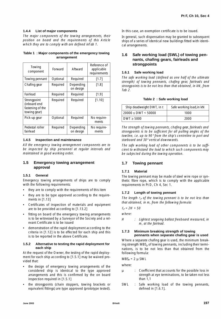
Pt F, Ch 10, Sec 4
1.4.4 List of major componentsThe major components of the towing arrangements, theirposition on board and the requirements of this Articlewhich they are to comply with are defined inTab 1.
Table 1 : Major components of the emergency towingarrangement
1.4.5 Inspection and maintenanceAll the emergency towing arrangement components are tobe inspected by ship personnel at regular intervals andmaintained in good working order.
1.5 Emergency towing arrangementapproval
1.5.1 GeneralEmergency towing arrangements of ships are to complywith the following requirements:
• they are to comply with the requirements of this item
• they are to be type approved according to the require-ments in [1.13]
• Certificates of inspection of materials and equipmentare to be provided according to [1.13.2]
• fitting on board of the emergency towing arrangementsis to be witnessed by a Surveyor of the Society and a rel-evant Certificate is to be issued
• demonstration of the rapid deployment according to thecriteria in [1.12] is to be effected for each ship and thisis to be reported in the above Certificate.
1.5.2 Alternative to testing the rapid deployment foreach ship
At the request of the Owner, the testing of the rapid deploy-ment for each ship according to [1.5.1] may be waived pro-vided that:
• the design of emergency towing arrangements of theconsidered ship is identical to the type approvedarrangements and this is confirmed by the on boardinspection required in [1.5.1]
• the strongpoints (chain stoppers, towing brackets orequivalent fittings) are type approved (prototype tested).
In this case, an exemption certificate is to be issued.
In general, such dispensation may be granted to subsequentships of a series of identical new buildings fitted with identi-cal arrangements.
1.6 Safe working load (SWL) of towing pen-nants, chafing gears, fairleads andstrongpoints
1.6.1 Safe working load
The safe working load (defined as one half of the ultimatestrength) of towing pennants, chafing gear, fairleads andstrongpoints is to be not less than that obtained, in kN, fromTab 2.
Table 2 : Safe working load
The strength of towing pennants, chafing gear, fairleads andstrongpoints is to be sufficient for all pulling angles of thetowline, i.e. up to 90° from the ship’s centreline to port andstarboard and 30° vertical downwards.
The safe working load of other components is to be suffi-cient to withstand the load to which such components maybe subjected during the towing operation.
1.7 Towing pennant
1.7.1 Material
The towing pennant may be made of steel wire rope or syn-thetic fibre rope, which is to comply with the applicablerequirements in Pt D, Ch 4, Sec 1.
1.7.2 Length of towing pennant
The length �P of the towing pennant is to be not less thanthat obtained, in m, from the following formula:
�P = 2H + 50
where:
H : Lightest seagoing ballast freeboard measured, inm, at the fairlead.
1.7.3 Minimum breaking strength of towingpennants when separate chafing gear is used
Where a separate chafing gear is used, the minimum break-ing strength MBSp of towing pennants, including their termi-nations, is to be not less than that obtained from thefollowing formula:
MBSP = 2 µ SWL
where:
µ : Coefficient that accounts for the possible loss instrength at eye terminations, to be taken not lessthan 1,1
SWL : Safe working load of the towing pennants,defined in [1.6.1].
Towingcomponent
Forward AftwardReference of applicable
requirements
Towing pennant Optional Required [1.7]
Chafing gear Required Depending on design
[1.8]
Fairlead Required Required [1.9]
Strongpoint (inboard end fastening of the towing gear)
Required Required [1.10]
Pick-up gear Optional Required No require-ments
Pedestal roller fairlead
Required Depending on design
No require-ments
Ship deadweight DWT, in t Safe working load,in kN
20000 ≤ DWT < 50000 1000
DWT ≥ 5000 2000
June 2003 BVmili 197

Pt F, Ch 10, Sec 4
1.7.4 Minimum breaking strength of towing pennantswhen no separate chafing gear is used
Where no separate chafing gear is used (i.e. where the tow-ing pennant may chafe against the fairlead during towingoperation), the minimum breaking strength of the towingpennants MBSPC is to be not less than that obtained, in kN,from the following formula:
MBSPC = ϕ ΜΒSP
where:
MBSP : Minimum breaking strength, in kN, defined in[1.7.3]
ϕ : Coefficient to be taken equal to:
ϕ may be taken equal to 1,0 if tests carried outunder a test load equal to twice the safe work-ing load defined in [1.6.1] demonstrate that thestrength of the towing pennants is satisfactory
ρ : Bending ratio (ratio between the minimumbearing surface diameter of the fairlead and thetowing pennant diameter), to be taken not lessthan 7.
1.7.5 Towing pennant termination
For towing connection, the towing pennant is to have a hardeye-formed termination allowing connection to a standardshackle.
Socketed or ferrule-secured eye terminations of the towingpennant are to be type tested in order to demonstrate thattheir minimum breaking strength is not less than twice thesafe working load defined in [1.6.1].
1.8 Chafing gear
1.8.1 General
Different solutions for the design of chafing gear may beused.
If a chafing chain is to be used, it is to have the characteris-tics defined in the following requirements.
1.8.2 TypeChafing chains are to be stud link chains.
1.8.3 MaterialIn general, grade Q3 chain cables and associated accesso-ries complying with the applicable requirements in Pt D,Ch 4, Sec 1 are to be used.
1.8.4 Chafing chain lengthThe chafing chain is to be long enough to ensure that thetowing pennant, or the towline, remains outside the fairleadduring the towing operation. A chain extending from thestrongpoint to a point at least 3m beyond the fairlead com-plies with this requirement.
1.8.5 Minimum breaking strengthThe minimum breaking strength of the stud link chafingchain and the associated links is to be not less than twicethe safe working load defined in [1.6.1].
1.8.6 Diameter of the common linksThe diameter of the common links of stud link chain cablesis to be not less than:• 52 mm for a safe working load, defined in [1.6.1], equal
to 1000 kN• 76 mm for a safe working load, defined in [1.6.1], equal
to 2000 kN.
1.8.7 Chafing chain endsOne end of the chafing chain is to be suitable for connec-tion to the strongpoint. Where a chain stopper is used, theinboard end of the chafing chain is to be efficiently securedin order to prevent any inadvertent loss of the chafing chainwhen operating the stopping device. Where the chafingchain is connected to a towing bracket, the correspondingchain end may be constructed as shown in Fig 2, but theinner dimension of the pear link may be taken as 5,30d(instead of 5,75d).The other end of the chafing chain is to be fitted with astandard pear-shaped open link allowing connection to astandard bow shackle. A typical arrangement of this chainend is shown in Fig 2. Arrangements different than thatshown in Fig 2 are considered by the Society on a case-by-case basis.
Figure 2 : Typical outboard chafing chain end
ϕ 2 ρ2 ρ 1–--------------------=
d
1,1d 1,2d 1,2d
2d 2,2d
Common links(diameter = d)
5,75 dapprox
Enlargedlink
Studlessend link
Pear shapedopen link
Towards
towing pennant
198 BVmili June 2003

Pt F, Ch 10, Sec 4
1.8.8 Storing
The chafing chain is to be stored and stowed in such a waythat it can be rapidly connected to the strongpoint.
1.9 Fairleads
1.9.1 General
Fairleads are normally to be of a closed type (such as Pan-ama chocks).
Fairleads are to have an opening large enough to pass thelargest portion of the chafing gear, towing pennant or tow-line. The corners of the opening are to be suitably rounded.
Where the fairleads are designed to pass chafing chains, theopenings are to be not less than 600mm in width and450mm in height.
1.9.2 Material
Fairleads are to be made of fabricated steel plates or otherductile materials such as weldable forged or cast steel com-plying with the applicable requirements of Part D, Chapter 2.
1.9.3 Operating condition
The bow and stern fairleads are to give adequate supportfor the towing pennant during towing operation, whichmeans bending 90° to port and and starboard side and 30°vertical downwards.
1.9.4 Positioning
The bow and stern fairleads are to be located so as to facili-tate towing from either side of the bow or stern and mini-mise the stress on the towing system.
The bow and stern fairleads are to be located as close aspossible to the deck and, in any case, in such a position thatthe chafing chain is approximately parallel to the deck whenit is under strain between the strongpoint and the fairlead.
Furthermore, the bow and stern fairleads are normally to belocated on the ship's centreline. Where it is practicallyimpossible to fit the towing fairleads exactly on the ship’scentreline, it may be acceptable to have them slightlyshifted from the centreline.
1.9.5 Bending ratio
The bending ratio (ratio between the towing pennant bear-ing surface diameter and the towing pennant diameter) is tobe not less than 7.
1.9.6 Fairlead lips
The lips of the fairlead are to be suitably faired in order toprevent the chafing chain from fouling on the lower lipwhen deployed or during towing.
1.9.7 Yielding check
The equivalent Von Mises stress σE, in N/mm2, induced inthe fairlead by a load equal to the safe working load definedin [1.6.1], is to comply with the following formula:
σE ≤ σALL
Areas subjected to stress concentrations are considered bythe Society on a case-by-case basis.
Where the fairleads are analysed through fine mesh finiteelement models, the allowable stress may be taken as1,1σALL.
1.9.8 Alternative to the yielding check
The above yielding check may be waived provided that fair-leads are tested with a test load equal to twice the safeworking load defined in [1.6.1] and this test is witnessed bya Surveyor of the Society. In this case, the Designer isresponsible for ensuring that the fairlead scantlings are suffi-cient to withstand such a test load.
Unless otherwise agreed by the Society, components sub-jected to this test load are considered as prototype itemsand are to be discarded.
1.10 Strongpoint
1.10.1 General
The strongpoint (inboard end fastening of the towing gear)is to be a chain cable stopper or a towing bracket or otherfitting of equivalent strength and ease of connection. Thestrongpoint can be designed integral with the fairlead.
The strongpoint is to be type approved according to [1.13]and is to be clearly marked with its SWL.
1.10.2 Materials
The strongpoint is to be made of fabricated steel or otherductile materials such as forged or cast steel complyingwith the applicable requirements of Part D, Chapter 2.
Use of spheroidal graphite cast iron (SG iron) may beaccepted for the main framing of the strongpoint providedthat:
• the part concerned is not intended to be a componentpart of a welded assembly,
• the SG iron is of ferritic structure with an elongation notless than 12%,
• the yield stress at 0,2% is measured and certified,
• the internal structure of the component is inspected bysuitable non-destructive means.
The material used for the stopping device (pawl or hingedbar) of chain stoppers and for the connecting pin of towingbrackets is to have mechanical properties not less than thoseof grade Q3 chain cables, defined in Pt D, Ch 4, Sec 1.
1.10.3 Typical strongpoint arrangement
Typical arrangements of chain stoppers and towing bracketsare shown in Fig 3, which may be used as reference.
June 2003 BVmili 199

Pt F, Ch 10, Sec 4
Figure 3 : Typical strongpoint arrangement
Chain stoppers may be of the hinged bar type or pawl(tongue) type or of other equivalent design.
1.10.4 Position and operating condition
The operating conditions and the positions of the strong-points are to comply with those defined in [1.9.3] and[1.9.4], respectively, for the fairleads.
1.10.5 Stopping device
The stopping device (chain engaging pawl or bar) is to bearranged, when in closed position, to prevent the chain
stopper from working in the open position, in order to avoidchain cable release and allow it to pay out.
Stopping devices are to be easy and safe to operate and, inthe open position, are to be properly secured.
1.10.6 Connecting pin of the towing bracket
The scantlings of the connecting pin of the towing bracketare to be not less than those of a pin of a grade Q3 endshackle, as shown in Fig 3, provided that clearancebetween the two side lugs of the bracket does not exceed2,0d, where d is the chain diameter specified in [1.8.6] (seealso Fig 2).
Pawl type chain stopper
Stopping device(tongue)
Securing pinin closed position
Securing pinin open position
Sliding track
Sliding track
Grade Q3 chafing chaincommon link diameter = d
2,2 d
2,2 d
Towardsfairlead
Towardsfairlead
Towardsfairlead
Thrust chock
Horizontal part ofsliding track ≥ 14 d
Horizontal part ofsliding track ≥ 14 d
Bar hinged type chain stopper
Stopping device(hinged bar)
3,5 d (approx.)
Towing bracket(*) : See [4.10.6]
Connecting pin (*)(steel grade Q3)
Twin lug bracket
1,4
d(*)
5,3 d
1,8 d(*)
Stu
dles
s en
d lin
k
Enl
arge
d lin
k
Common links(diameter = d)
3,5
dap
prox
.
14 d(approx.)
200 BVmili June 2003

Pt F, Ch 10, Sec 4
1.10.7 Yielding checkThe equivalent Von Mises stress σE , in N/mm2, induced inthe strongpoint by a load equal to the safe working loaddefined in [1.6.1], is to comply with the following formula:
σE ≤ σALL
Areas subjected to stress concentrations are considered bythe Society on a case-by-case basis.
Where the strongpoints are analysed through fine meshfinite element models, the allowable stress may be taken as1,1 σALL.
1.10.8 Alternative to the yielding checkThe above yielding check may be waived provided thatstrongpoints are tested with a test load equal to twice thesafe working load defined in [1.6.1] and this test is wit-nessed by a Surveyor. In this case, the Designer is responsi-ble for ensuring that the fairlead scantlings are sufficient towithstand such a test load.
Unless otherwise agreed by the Society, components sub-jected to this test load are considered as prototype itemsand are to be discarded.
1.10.9 Bolted connectionWhere a chain stopper or a towing bracket is bolted to aseating welded to the deck, the bolts are to be relieved fromshear force by means of efficient thrust chocks capable ofwithstanding a horizontal force equal to 1,3 times the safeworking load defined in [1.6.1] within the allowable stressdefined in [1.10.7].
The steel quality of bolts is to be not less than grade 8.8 asdefined by ISO standard No. 898/1.
Bolts are to be pre-stressed in compliance with appropriatestandards and their tightening is to be suitably checked.
1.11 Hull structures in way of fairleads orstrongpoints
1.11.1 Materials and weldingThe materials used for the reinforcement of the hull struc-ture in way of the fairleads or the strongpoints are to complywith the applicable requirements of Part D.
Main welds of the strongpoints with the hull structure are tobe 100% inspected by adequate non-destructive tests.
1.11.2 Yielding check of bulwark and staysThe equivalent Von Mises stress σE , in N/mm2, induced inthe bulwark plating and stays in way of the fairleads by aload equal to the safe working load defined in [1.6.1], forthe operating condition of the fairleads defined in [1.9.3], isto comply with the following formula:
σE ≤ σALL
1.11.3 Yielding check of deck structuresThe equivalent Von Mises stress σE , in N/mm2, induced inthe deck structures in way of chain stoppers or towingbrackets, including deck seatings and deck connections, bya horizontal load equal to 1,3 times the safe working loaddefined in [1.6.1], is to comply with the following formula:
σE ≤ σALL
1.11.4 Minimum gross thickness of deck platingThe gross thickness of the deck is to be not less than:• 12 mm for a safe working load, defined in [1.6.1], equal
to 1000 kN• 15 mm for a safe working load, defined in [1.6.1], equal
to 2000 kN.
1.12 Rapid deployment of towing arrange-ment
1.12.1 GeneralTo facilitate approval of towing arrangements and to ensurerapid deployment, emergency towing arrangements are tocomply with the requirements of this item.
1.12.2 MarkingAll components, including control devices, of the emer-gency towing arrangements are to be clearly marked tofacilitate safe and effective use even in darkness and poorvisibility.
1.12.3 Aft arrangementThe aft emergency towing arrangement is to be pre-riggedand be capable of being deployed in a controlled manner inharbour conditions in not more than 15 minutes.The pick-up gear for the aft towing pennant is to bedesigned at least for manual operation by one person takinginto account the absence of power and the potential foradverse environmental conditions that may prevail duringsuch emergency towing operations.The pick-up gear is to be protected against the weather andother adverse conditions that may prevail.
1.12.4 ForwardThe forward emergency towing arrangement is to be capa-ble of being deployed in harbour conditions in not morethan 1 hour.The forward emergency towing arrangement is to bedesigned at least with a means of securing a towline to thechafing gear using a suitably positioned pedestal roller tofacilitate connection of the towing pennant.Forward emergency towing arrangements which complywith the requirements for aft emergency towing arrange-ments may be accepted.
1.13 Type approval
1.13.1 Type approval procedureEmergency towing arrangements are to be type approvedaccording to the following procedure:• the arrangement design is to comply with the require-
ments of this Section• each component of the towing arrangement is to be
tested and its manufacturing is to be witnessed and cer-tified by a Surveyor according to [1.13.2]
• prototype tests are to be carried out in compliance with[1.13.3].
1.13.2 Inspection and certificationThe materials and equipment are to be inspected and certi-fied as specified inTab 3 .
June 2003 BVmili 201

Pt F, Ch 10, Sec 4
1.13.3 Prototype tests
Prototype tests are to be witnessed by a Surveyor and are toinclude the following:
• demonstration of the rapid deployment according to thecriteria in [1.12]
• load test of the strongpoints (chain stoppers, towingbrackets or equivalent fittings) under a proof load equalto 1,3 times the safe working load defined in [1.6.1].
A comprehensive test report duly endorsed by the Surveyoris to be submitted to the Society for review.
Table 3 : Material and equipment certification status
ComponentMaterial Equipment
Certificate Reference of applicable requirements Certificate Reference of applicable
requirements
Towing pennant Not applicable [1.7.1] COI (1) [1.7]
Chafing chain and associated accessories
COI (2) [1.8.3] COI (1) [1.8]
Fairleads CW [1.9.2] COI [1.9]
Strongpoint: COI (3) [1.10]
• main framing COI (2) [1.10.2]
• stopping device COI (2) [1.10.2]
Pick-up gear: No requirements
• rope Not applicable - CW
• buoy Not applicable - Not required (4)
• line-throwing appliance Not applicable - Not required (4)
Pedestal roller fairlead CW - Not required (4) No requirements
(1) according to Pt D, Ch 4, Sec 1.(2) according to Part D, Chapter 1.(3) to be type approved.(4) may be type approved.Note 1:COI : Certificate of inspection,CW : Works’ certificate 3.1.B according to EN 10204.
202 BVmili June 2003


