Embed Size (px)
Citation preview
Part-load flow instabilities in a radial pump measured with TR-PIV
NICO KRAUSE, ELEMER PAP, DOMINIQUE THEVENIN Laboratory of Fluid Dynamics and Technical Flows
University of Magdeburg ''Otto von Guericke'' Universitaetsplatz 2 D-39106 Magdeburg
GERMANY
Abstract: - Pumps are used in a variety of important applications. Often, the pipe characteristic is unsatisfactory known and the selected pump has more power than needed. It will thus be throttled or the flow is throttled during operation. In such cases the pump operates under part-load flow and the inflow condition differs from the dimensioning point. In this paper results for an impeller blade designed using a single arc of a circle are presented. The pump characteristic curve shows energy transmission and losses. For the investigation of the flow in the impeller Time-resolved Particle Image Velocimetry (TR-PIV) is used. Using TR-PIV it is possible to visualise the vortices in the stall regime. The results have been obtained at different operating points. It is possible to observe different stages of the developing rotating stall. The first vortices are observed at a throttled flow rate of 50% of the design point. They exist only in two channels of the impeller. The first rotations of the stall cell through the impeller are observed at flow rates smaller than 40% of the design point. These velocity fields are further post-processed to analyze the possible development of the rotating stall cell. Key-Words: rotating stall, radial pump, turbomachinery, blade design, TR-PIV, pump characteristic, part-load flow
1 Introduction In many applications pumps are not used at the design point. Wurm [1] indicates that in head installations pumps operate at under 25% of the design flow-rate over 50% of the time. In such cases the pump operates under part-load flow and the inflow condition differs from the dimensioning point. For turbomachines operating with gases the problem of rotating stall has been known for a long time. The first description was given by Emmons et al. [2]. In turbomachines there exists a well-known velocity triangle with the components c (absolute velocity), u (peripheral velocity) and w (relative velocity) (Eq. 1, Fig. 1a). c u w= + (1) If the flow rate is reduced, the meridian component of the relative velocity wm also decreases (Fig. 1b). For this reduced flow rate the angle of attack rises and the stagnation point is displaced to the pressure side of the blade. When the angle of attack exceeds a certain threshold, the flow on the suction side will detach and stall can appear. The static pressure inside the stall region is smaller than in the surrounding flow; vortices can therefore appear with the same rotating direction as the impeller. In the outlet of the blade passage a second vortex can be formed with an inverse rotational direction. These vortices can grow until the complete blade passage is blocked. Then, the medium has to pass through the
following channel. This leads once more to a displacement of the stagnation point in the following blade passage, and a new stall cell will be formed in this channel. On the other hand, the flow in the first blade passage will reattach and the flow conditions in this channel will improve. It is furthermore possible that several stall cells exist simultaneously in the impeller.
a) b)
Fig.1a-b Velocity triangles at design point (a) and for throttled flow (b). With this mechanism the stall cell(s) can turn around through the impeller. Because the angular velocity of the stall cell is lower than the impeller angular velocity, it turns inside the impeller against the rotational direction.
Proceedings of the 4th WSEAS International Conference on Fluid Mechanics and Aerodynamics, Elounda, Greece, August 21-23, 2006 (pp319-324)

Rotating stall leads to considerable efficiency losses. Many studies have investigated this phenomenon, mostly in axial compressors [3-5]. Pampreen [6] gives an extensive review of this problem. A limitation of all these studies is that they are based on high frequency single-point measurements of pressure [7-12], temperature or velocity [5,9,13,14], obtained through intrusive diagnostics, or on very low frequency non-intrusive imaging techniques [15]. But, for such instabilities, intrusive measurements can easily falsify the results. A first investigation relying on a high frequency non-intrusive imaging technique was presented by Krause et al. [16]. In the present study, velocity fields measured in a centrifugal pump with Time-resolved PIV at high frame rates are presented. These measurements concerning instabilities and turbulent processes clearly show rotating stall in a throttled radial water pump.
2 EXPERIMENTAL SET-UP The set-up used in the experiments consists in two major parts: the Time-resolved PIV system and the rotating machinery installation. Fig. 2 shows a sketch of this installation, where the pipes and the acryl model pump can be distinguished.
Fig.2 Sketch of the radial transparent pump installation with PIV measurement system.
2.1 Radial pump For the design of pump blades different concepts are used. The inlet and outlet angles are given by the needed pressure difference and remain the same for all geometries. One simple concept is a blade geometry given by one circular arc with a single radius. The advantages are: short length of the mean line, small hydraulic losses and simple structure. The disadvantage is the fast deceleration of the flow in the first third of the blade passage and acceleration near the outlet. The corresponding geometry is presented in Fig. 3 and is retained in the present study. A meridian section of the pump is presented in Fig. 4. Fig. 5 shows the relative velocity over the mean line for the design point where the fast deceleration of the flow
in the first third of the blade passage is visible. Technical parameters are listed in Table 1.
Fig. 3 Geometry of the impeller.
Fig.4 Meridian section of the pump.
0
1
2
3
4
5
6
0,00 0,02 0,04 0,06 0,08 0,10 0,12 0,14 0,16Lenght of mean line s in m
w [m
/s]
Fig.5 Relative velocity over the mean line of the blade.
Table 1. Technical parameters of the pump
Qd 47 [m³/h] Flow rate design point n 600 [min-1] Number of revolutions β1 19 [°] Inlet angle β2 23 [°] Outlet angle r1 65 [mm] Inlet radius r2 139 [mm] Outlet radius nq 26 [min-1] Specific speed
Proceedings of the 4th WSEAS International Conference on Fluid Mechanics and Aerodynamics, Elounda, Greece, August 21-23, 2006 (pp319-324)
2.2 Measuring system For the velocity measurements a commercial Time-resolved PIV system from DantecDynamics A/S is used. The principles of PIV are described e.g. by Willert et al. [17]. The TR-PIV-system is composed of a Q-switched Nd:YAG laser, laser-sheet optics, a CMOS double-image camera, a synchronisation unit and the control, acquisition and treatment computer. The frequency-doubled, diode-pumped Nd:YAG laser has a variable repetition rate, allowing pulse intervals from 40 to 1000 µs, with a pulse duration of 75-250 ns. The pulse energy strongly depends on the repetition rate with a maximum energy of about 22 mJ at lower repetition rates. The light sheet optics have been adjusted in order to get a diverging light sheet of 0.5-1 mm thickness inside the pump. The PIV images were taken with a 1260x1024 pixel, 10 bit CMOS camera, working with frame rates up to 500 image pairs/s full frame and 800 images pairs/s with 1260x640 pixels. For the investigation frequencies of 50 and 800 Hz have been used. The frequency of 50 Hz corresponds to a measurement of each blade of the impeller in a fixed position. To follow the vortices within one channel the higher frequency is used. The seeding material consists in Rhodamin-B-doped PMMA-particles with a mean size of 10 µm and a density ρ=1,19 kg/dm³. To measure the static pressure rise the pressure before the impeller in the suction side and after the impeller at r=160 mm was recorded. The velocity energy after the impeller at the same radius is calculated from the PIV-data.
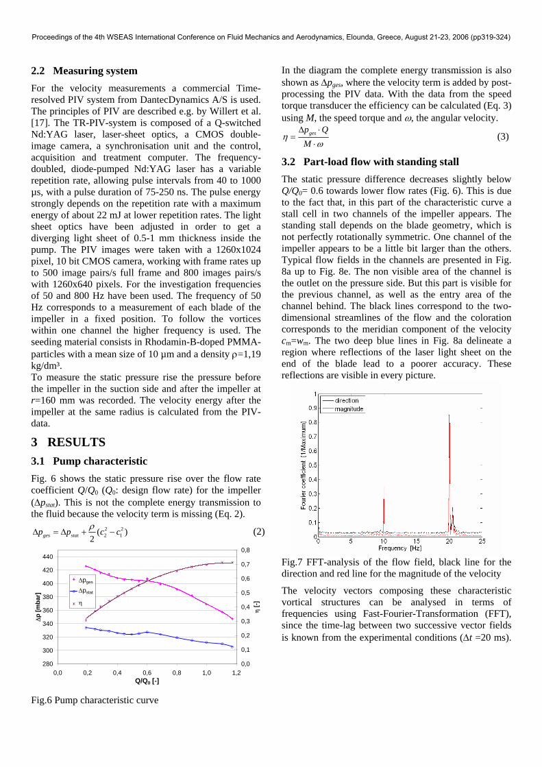
3 RESULTS 3.1 Pump characteristic Fig. 6 shows the static pressure rise over the flow rate coefficient Q/Q0 (Q0: design flow rate) for the impeller (Δpstat). This is not the complete energy transmission to the fluid because the velocity term is missing (Eq. 2).
2 22 1(
2ges statp p c cρΔ = Δ + − ) (2)
280
300
320
340
360
380
400
420
440
0,0 0,2 0,4 0,6 0,8 1,0 1,2Q/Q0 [-]
Δp
[mba
r]
0,0
0,1
0,2
0,3
0,4
0,5
0,6
0,7
0,8
η [-]
DpgesDpstatη
Δpges
Δpstat
η
Fig.6 Pump characteristic curve
In the diagram the complete energy transmission is also shown as Δpges, where the velocity term is added by post-processing the PIV data. With the data from the speed torque transducer the efficiency can be calculated (Eq. 3) using M, the speed torque and ω, the angular velocity.
gesp QM
ηω
Δ ⋅=
⋅ (3)
3.2 Part-load flow with standing stall The static pressure difference decreases slightly below Q/Q0= 0.6 towards lower flow rates (Fig. 6). This is due to the fact that, in this part of the characteristic curve a stall cell in two channels of the impeller appears. The standing stall depends on the blade geometry, which is not perfectly rotationally symmetric. One channel of the impeller appears to be a little bit larger than the others. Typical flow fields in the channels are presented in Fig. 8a up to Fig. 8e. The non visible area of the channel is the outlet on the pressure side. But this part is visible for the previous channel, as well as the entry area of the channel behind. The black lines correspond to the two-dimensional streamlines of the flow and the coloration corresponds to the meridian component of the velocity cm=wm. The two deep blue lines in Fig. 8a delineate a region where reflections of the laser light sheet on the end of the blade lead to a poorer accuracy. These reflections are visible in every picture.
Fig.7 FFT-analysis of the flow field, black line for the direction and red line for the magnitude of the velocity
The velocity vectors composing these characteristic vortical structures can be analysed in terms of frequencies using Fast-Fourier-Transformation (FFT), since the time-lag between two successive vector fields is known from the experimental conditions (Δt =20 ms).
Proceedings of the 4th WSEAS International Conference on Fluid Mechanics and Aerodynamics, Elounda, Greece, August 21-23, 2006 (pp319-324)
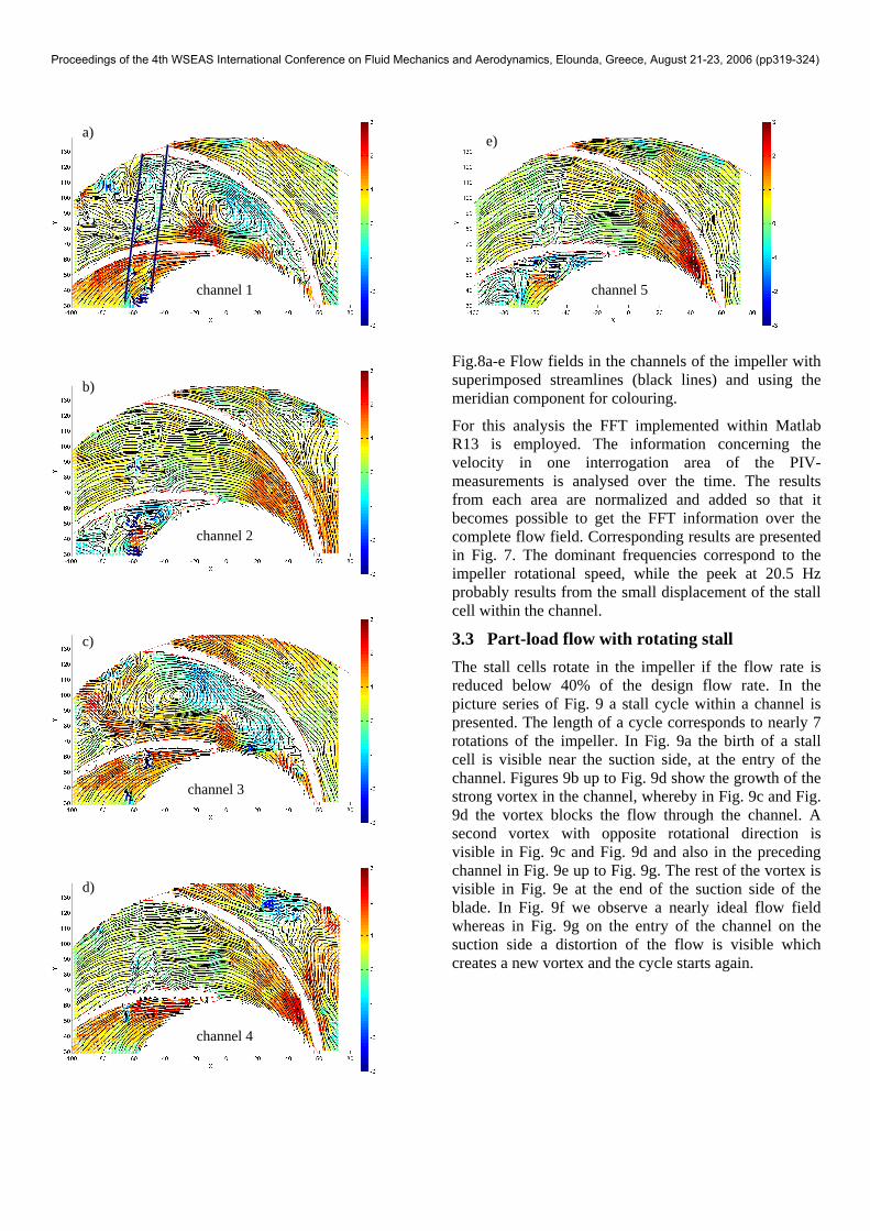
a) e)
channel 1 channel 5
Fig.8a-e Flow fields in the channels of the impeller with superimposed streamlines (black lines) and using the meridian component for colouring.
b)
For this analysis the FFT implemented within Matlab R13 is employed. The information concerning the velocity in one interrogation area of the PIV-measurements is analysed over the time. The results from each area are normalized and added so that it becomes possible to get the FFT information over the complete flow field. Corresponding results are presented in Fig. 7. The dominant frequencies correspond to the impeller rotational speed, while the peek at 20.5 Hz probably results from the small displacement of the stall cell within the channel.
channel 2
3.3 Part-load flow with rotating stall c)
The stall cells rotate in the impeller if the flow rate is reduced below 40% of the design flow rate. In the picture series of Fig. 9 a stall cycle within a channel is presented. The length of a cycle corresponds to nearly 7 rotations of the impeller. In Fig. 9a the birth of a stall cell is visible near the suction side, at the entry of the channel. Figures 9b up to Fig. 9d show the growth of the strong vortex in the channel, whereby in Fig. 9c and Fig. 9d the vortex blocks the flow through the channel. A second vortex with opposite rotational direction is visible in Fig. 9c and Fig. 9d and also in the preceding channel in Fig. 9e up to Fig. 9g. The rest of the vortex is visible in Fig. 9e at the end of the suction side of the blade. In Fig. 9f we observe a nearly ideal flow field whereas in Fig. 9g on the entry of the channel on the suction side a distortion of the flow is visible which creates a new vortex and the cycle starts again.
channel 3
d)
channel 4
Proceedings of the 4th WSEAS International Conference on Fluid Mechanics and Aerodynamics, Elounda, Greece, August 21-23, 2006 (pp319-324)
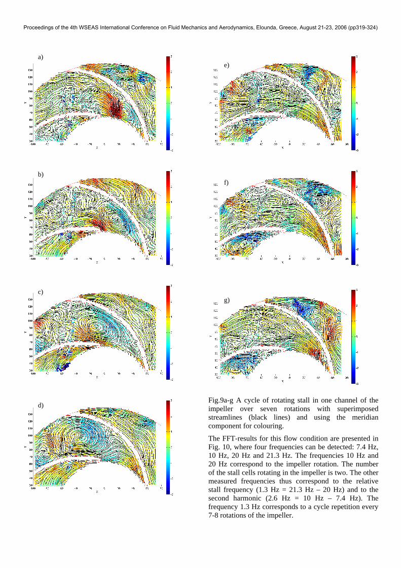
a) e)
b) f)
c) g)
Fig.9a-g A cycle of rotating stall in one channel of the impeller over seven rotations with superimposed streamlines (black lines) and using the meridian component for colouring.
d)
The FFT-results for this flow condition are presented in Fig. 10, where four frequencies can be detected: 7.4 Hz, 10 Hz, 20 Hz and 21.3 Hz. The frequencies 10 Hz and 20 Hz correspond to the impeller rotation. The number of the stall cells rotating in the impeller is two. The other measured frequencies thus correspond to the relative stall frequency (1.3 Hz = 21.3 Hz – 20 Hz) and to the second harmonic (2.6 Hz = 10 Hz – 7.4 Hz). The frequency 1.3 Hz corresponds to a cycle repetition every 7-8 rotations of the impeller.
Proceedings of the 4th WSEAS International Conference on Fluid Mechanics and Aerodynamics, Elounda, Greece, August 21-23, 2006 (pp319-324)
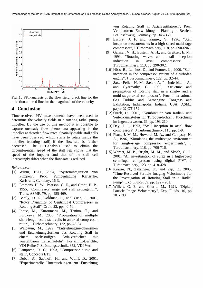
Fig. 10 FFT-analysis of the flow field, black line for the direction and red line for the magnitude of the velocity
4 Conclusion Time-resolved PIV measurements have been used to determine the velocity fields in a rotating radial pump impeller. By the use of this method it is possible to capture unsteady flow phenomena appearing in the impeller at throttled flow rates. Spatially-stable stall cells have been observed, which starts to rotate inside the impeller (rotating stall) if the flow-rate is further decreased. The FFT-analysis used to obtain the circumferential speed of the stall cell shows that the speed of the impeller and that of the stall cell increasingly differ when the flow-rate is reduced. References: [1] Wurm, F.-H., 2004, "Systemintegration von
Pumpen", Proc. Pumpentagung Karlsruhe, Karlsruhe, Germany, 16-3.
[2] Emmons, H. W., Pearson, C. E., and Grant, H. P., 1955, "Compressor surge and stall propagation", Trans. ASME, 79, pp. 455-469.
[3] Bently, D. E., Goldman, P., and Yuan, J., 2001, "Rotor Dynamics of Centrifugal Compressors in Rotating Stall", Orbit, 22, pp. 40-50.
[4] Inoue, M., Kuroumaru, M., Tanino, T., and Furukawa, M., 2000, "Propagation of multiple short-length-scale stall cells in an axial compressor rotor", J Turbomachinery, 122, pp. 45-54.
[5] Walbaum, M., 1999, "Entstehungsmechanismen und Erscheinungsformen des Rotating Stall in einem sechsstufigen Axialverdichter mit verstellbaren Leitschaufeln", Fortschritt-Berichte, VDI Reihe 7, Strömungstechnik, 352, VDI Verl.
[6] Pampreen, R. C., 1993, "Compressor surge and stall", Concepts ETI.
[7] Dobat, A., Saathoff, H., and Wulff, D., 2001, "Experimentelle Untersuchungen zur Entstehung
von Rotating Stall in Axialventilatoren", Proc. Ventilatoren: Entwicklung - Planung - Betrieb, Braunschweig, Germany, pp. 345-360.
[8] Escuret, J. F. and Garnier, V., 1996, "Stall inception measurements in a high-speed multistage compressor", J Turbomachinery, 118, pp. 690-696.
[9] Garnier, V. H., Epstein, A. H., and Greitzer, E. M., 1991, "Rotating waves as a stall inception indication in axial compressors", J Turbomachinery, 113, pp. 290-302.
[10] Höss, B., Leinhos, D., and Fottner, L., 2000, "Stall inception in the compressor system of a turbofan engine", J Turbomachinery, 122, pp. 32-44.
[11] Saxer-Felici, H. M., Saxer, A. P., Inderbitzin, A., and Gyarmathy, G., 1999, "Structure and propagation of rotating stall in a single- and a multi-stage axial compressor", Proc. International Gas Turbine and Aeroengine Congress and Exhibition, Indianapolis, Indiana, USA, ASME paper 99-GT-152.
[12] Surek, D., 2001, "Kombination von Radial- und Seitenkanalstufen für Turboverdichter", Forschung im Ingenieurwesen, 66, pp. 193-210.
[13] Day, I. J., 1993, "Stall inception in axial flow compressors", J Turbomachinery, 115, pp. 1-9.
[14] Place, J. M. M., Howard, M. A., and Cumpsty, N. A., 1996, "Simulating the multistage environment for single-stage compressor experiments", J Turbomachinery, 118, pp. 706-716.
[15] Wernet, M. P., Bright, M. M., and Skoch, G. J., 2001, "An investigation of surge in a high-speed centrifugal compressor using digital PIV", J Turbomachinery, 123, pp. 418-428.
[16] Krause, N., Zähringer, K., and Pap, E., 2005, "Time-Resolved Particle Imaging Velocimetry for the Investigation of Rotating Stall in a Radial Pump", Exp. Fluids, 39, pp. 192 - 201.
[17] Willert, C. E. and Gharib, M., 1991, "Digital Particle Image Velocimetry", Exp. Fluids, 10, pp 181-193.
Proceedings of the 4th WSEAS International Conference on Fluid Mechanics and Aerodynamics, Elounda, Greece, August 21-23, 2006 (pp319-324)