Embed Size (px)
Citation preview
I I
i
c
NASA/TM-2003-212S36/REVI AIAA-2003-4934
Control of Thermo-Acoustics Instabilities: The Multi-Scale Extended Kalman Approach
Dzu K. Le, John C. DeLaat, and Clarence T. Chang Glenn Research Center, Cleveland, Ohio
October 2003 l I
_J
https://ntrs.nasa.gov/search.jsp?R=20030068104 2018-07-06T19:54:12+00:00Z
The NASA STI Program Office ... in Profile
Since its founding, NASA has been dedicated to the advancement of aeronautics and space science. The NASA Scientific and Technical Information (STI) Program Office plays a key part in helping NASA maintain this important role.
The NASA STI Program Office is operated by Langley Research Center, the Lead Center for NASA's scientific and technical information. The NASA STI Program Office provides access to the NASA STI Database, the largest collection of aeronautical and space science STI in the world. The Program Office is also NASA's institutional mechanism for disseminating the results of its research and development activities. These results are published by NASA in the NASA STI Report Series, which includes the following report types:
• TECHNICAL PUBLICATION. Reports of completed research or a major significant phase of research that present the results of NASA programs and include extensive data or theoretical analysis. Includes compilations of significant scientific and technical data and information deemed to be of continuing reference value. NASA's counterpart of peerreviewed formal professional papers but has less stringent limitations on manuscript length and extent of graphic presentations.
• TECHNICAL MEMORANDUM. Scientific and technical findings that are preliminary or of specialized interest, e.g., quick release reports, working papers, and bibliographies that contain minimal annotation. Does not contain extensive analysis.
• CONTRACTOR REPORT. Scientific and technical findings by NASA-sponsored contractors and grantees.
• CONFERENCE PUBLICATION. Collected papers from scientific and technical conferences, symposia, seminars, or other meetings sponsored or cosponsored by NASA.
• SPECIAL PUBLICATION. Scientific, technical, or historical information from NASA programs, projects, and missions, often concerned with subjects having substantial public interest.
• TECHNICAL TRANSLATION. Englishlanguage translations of foreign scientific and technical material pertinent to NASA's mISSIon.
Specialized services that complement the STI Program Office's diverse offerings include creating custom thesauri, building customized databases, organizing and publishing research results ... even providing videos.
For more information about the NASA STI Program Office, see the following:
• Access the NASA STI Program Home Page at http://www.sti.nasa.gov
• E-mail your question via the Internet to [email protected]
• Fax your question to the NASA Access Help Desk at 301-621-0134
• Telephone the NASA Access Help Desk at 301-621-0390
• Write to: NASA Access Help Desk NASA Center for AeroSpace Information 7121 Standard Drive Hanover, MD 21076

:---- -
I
-- ---- --- -~----
NASA/TM-2003-212536/REVI AIAA-2003-4934
Control of Thermo-Acoustics Instabilities: The Multi-Scale Extended Kalman Approach
Dzu K. Le, John C. DeLaat, and Clarence T. Chang Glenn Research Center, Cleveland, Ohio
Prepared for the 39th Joint Propulsion Conference and Exhibit cosponsored by the AIAA, ASME, SAE, and ASEE Huntsville, Alabama, July 20-23,2003
National Aeronautics and Space Administration
Glenn Research Center
October 2003
j
Acknowledgments
The authors sincerely thank Dr. Daniel Paxson and Mr. Daniel Vmak for their efforts in model and simulation developments to validate this control design. We also greatly appreciate the contributions of the United Technology
Research Center team to this research, especially Dr. Andrzej Banaszuk, for his invaluable insights and modeling data. Funding support for this work has been provided by the NASA Smart Efficient Components Project through
the help of Project manager, Robert Corrigan, with partial support for advanced control developments by the Strategic Research Fund (SRF) and the Aerospace Flywheel Technology Program.
Document Change History
This printing, numbered as NASAffM-2003-212536/REVl, October 2003, replaces the previous version,
NASAffM-2003-212536, August 2003. The reference numbers on page 3, paragraph 4, line 6, have been changed.
The Propulsion and Power Program at NASA Glenn Research Center sponsored this work.
Available from
NASA Center for Aerospace Information 7121 Standard Drive
National Technical Information Service 5285 Port Royal Road Springfield, VA 22100 Hanover, MD 21076
Available electronically at http: II gltrs.grc.nasa.gov
CONTROL OF THERMO-ACOUSTICS INSTABILITIES: THE MULTI-SCALE EXTENDED KALMAN APPROACH
Dzu K. Le, John C. DeLaat, and Clarence T. Chang National Aeronautics and Space Administration
Glenn Research Center Cleveland, Ohio
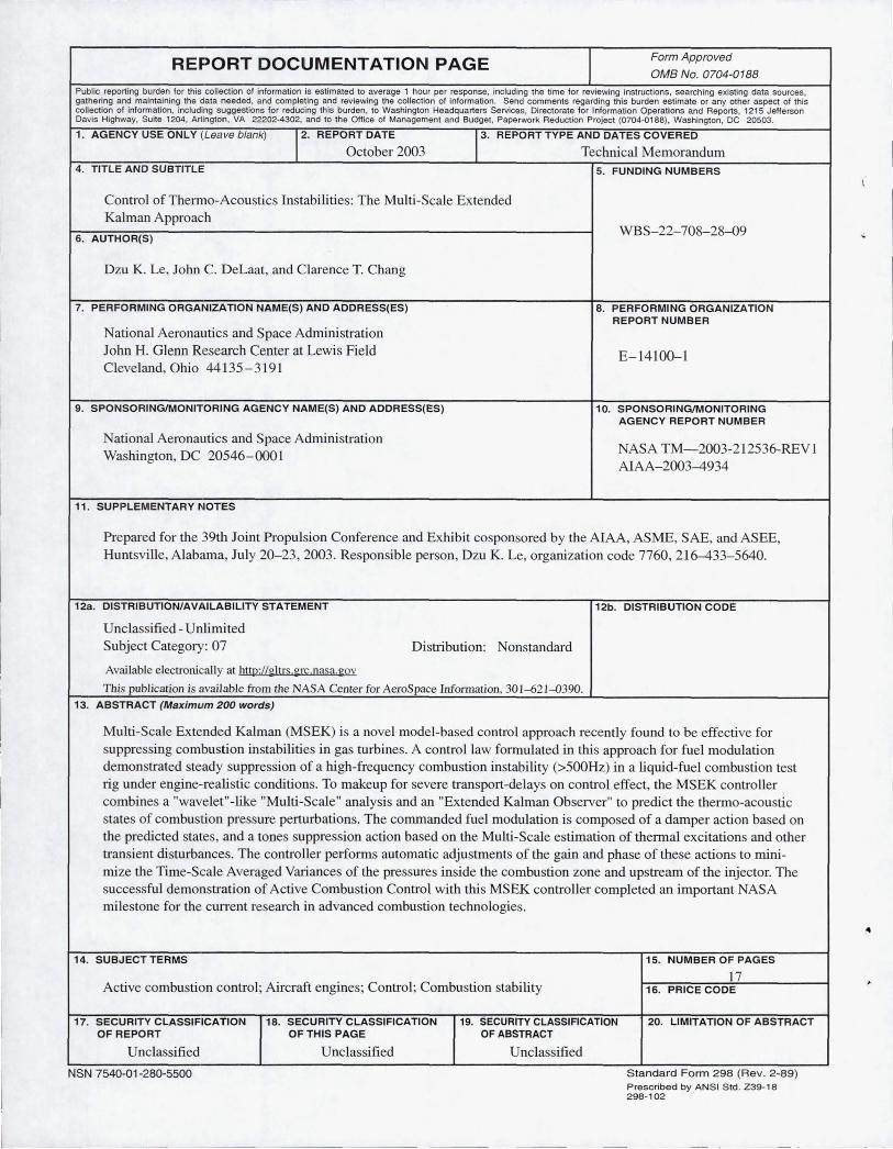
ABSTRACT
"Multi-Scale Extended Kalman" (MSEK) is a novel modelbased control approach recently found to be effective for suppressing combustion instabilities in gas turbines. A control law formulated in this approach for fuel modulation demonstrated steady suppression of a high-frequency combustion instability (>500Hz) in a liquid-fuel combustion test rig under engine-realistic conditions. To make-up for severe transport-delays on control effect, the MSEK controller combines a "wavelet"-like "Multi-Scale" analysis and an "Extended KaLman Observer" to predict the themlo-acoustic states of combustion pressure perturbations. The commanded fuel modulation is composed of a damper action based on the predicted states, and a tones suppression action based on the Multi-Scale estimation of thermal excitations and other tran ient disturbances. The controller performs automatic adjustments of the gain and phase of these actions to minimize the Time-Scale Averaged Variances of the pressmes inside the combustion zone and upstream of the injector. The successfu l demonstration of Active Combustion Contro l with this MSEK controller completed an important NASA milestone for the cun-ent research in advanced combustion technologies.
1. INTRODUCTION
Combustor instability control is an enabling technology for superior engine perfOlTIlance. Acoustic resonances driven by heat release fluctuations can produce large pressure oscillations inside the combustion chamber. I These themloacoustic instabilities can potentially lead to premature mechanical failures. In the quest to reduce particulate and NOx emission, future aero-engine combustors will likely have lean-burning front-ends. As the ground-based gas-turbine field has experienced, however, lean-buming combustors are more susceptib le to combustion instabilities due to the more homogeneous transmission mediUl1l (an environment favorable for the forming of distinct acoustics modes); less damping from reduced or el iminated liner film cooling; and more energetic pertmbation somces from the more vigorous fuel-air mixing.
Active control of combustion instabilities by properly-phased fuel modulation is a very promising method for instability control in aero-engines. Conceptually, control of combustion instability pressure can be achieved by other means 2 . ... . 14. However, these other means (e.g. , speaker actuation) tend to
NASAlTM- 2003-212536/REVI
be bulky, have limited operating range, or have other undesirable side effects. In comparison, liquid fuel modulation is compact, more practical , and can deliver the most energy with the least effort.
The ASA Gleill1 Research Center (GRC) Active Combustion Control (ACC) tec!ulo!oGY effort aims to demonstrate active control in a realistic and relevant environment by providing experiments tied to aircraft ga -turbine engines. The first successful demonstration of active control of a High Frequency (Hf; >500Hz) thenno-acoustic instability via fuel modulation under engine-realistic conditions was accomplished in June 2002 by the ASA GRC effort. It was reaffu-rned in September 2002 with additional experiments and improved results. These experiments were done in collaboration with Pratt Whitney 14.15.16 at the United Technology Research Center (UTRC), on the NASA Single
ozzle Combustion Rig (SNR).
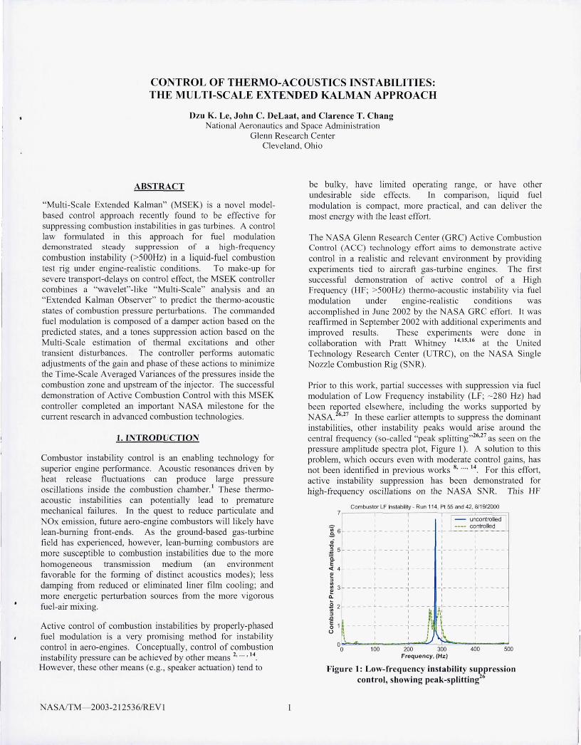
Prior to this work, partial successes with suppression via fuel modulation of Low frequency instability (Lf; - 280 Hz) had been reported elsewhere, including the works supported by NASA. 26.27 In these earlier attempts to suppress the dominant instabilities, other instability peaks would arise around the central frequency (so-called "peak splitting,,26.27 as seen on the pressure amplitude spectra plot, figure 1). A so lution to this problem, which occurs even with moderate control gains, has not been identified in previous works 8 • ... • 14 for this effort, active instability suppression has been demonstrated for high-frequency oscil lations on the NASA SNR. This Hf
Combustor LF Inslability - Run 114, PI SS and 42, 8119/2000
1 1- uncontrolled I 1 - --- controlled
-1-~6 oj ~ 5 ___________ -: ____ _ t ______ ~ ____ _
a. I E 1
<I: 4 ,
J 3 ~ - - - - - - -- - - - ~- -- - -:- - -- - - - - -- --
~ 1 J
] 2 ~ - - - - - ~ -- - - -:- -- ) - ~:- - -- - - - - - ---
E , I I I': ~ o 1t T , -- tiT -r-
U /1 : ,. \ j ~
00 100 200 300 400 500 Frequency. (Hz)
Figure 1: Low-frequency instability suppression control, showing peak-splitting26
0.4
~
<fJ
Eo 0 .3
I I I I ~ Engine , I f-------.
~~ " Rig " IAII["
Q)
-0 II .-2 II 0- 0 .2 E «
.. .. aI !tiM. .A.
,~ 1\
0 .1
YJ "1' 1"Y'1 ~ ~ '\
":: 1 ~ ~ I I ..
~~, '\\00 -'" .~ \ .jo J', "" VI "'- .. - -o 0 100 200 300 400 500 600 700 800 900 1000
Frequency (Hz)
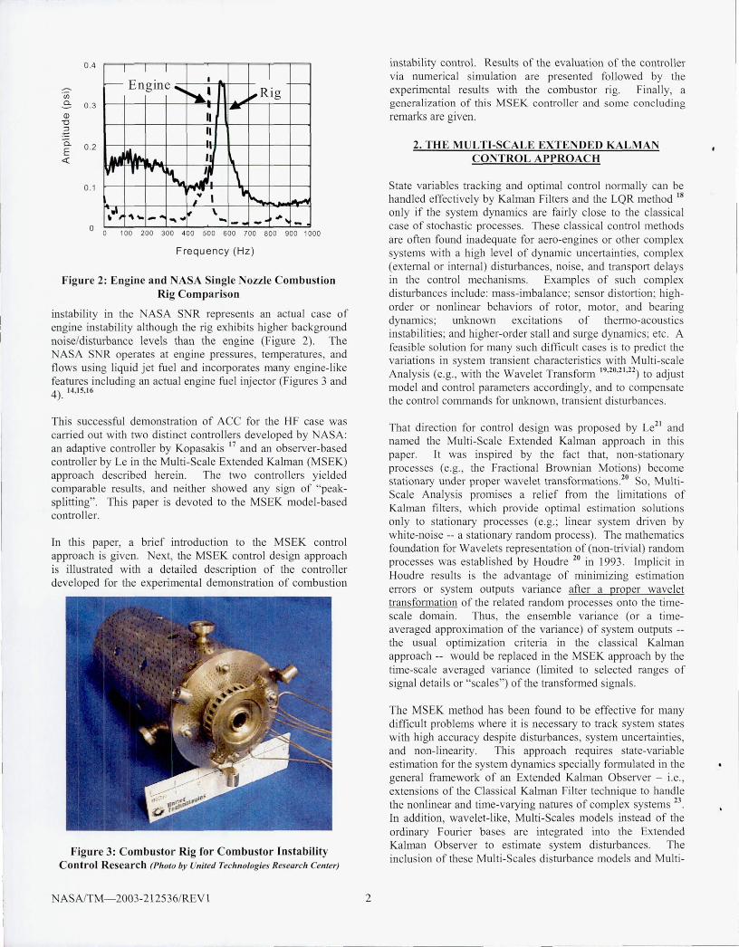
Figure 2: Engine and NASA Single Nozzle Combustion Rig Com parison
instability in the NASA SNR represents an actual case of engine i.nstability although the rig exhibits higher background noise/disturbance levels than the engine (Figure 2). The NASA S R operates at engine pressmes, temperatures, and flows using liquid jet fuel and incorporates many engine-l ike features including an actual engine fuel injector (Figmes 3 and 4) . 14, 15, 16
This successful demonstration of ACC for the HF case was carried out with two distinct controllers developed by NASA: an adaptive controller by Kopasakis 17 and an observer-based controller by Le in the Multi-Scale Extended Ka lman (MSEK) approach described herein. The two controllers yie lded comparable results, and neither showed any sign of "peaksplitting". This paper is devoted to the MSEK model-based controller.
In thi paper, a brief introduction to the MSEK contro l approach is given. Next, the MSEK control design approach is illustrated with a detailed description of the controller developed for the experimenta l demonstration of combustion
F igure 3: Combustor Rig for Combustor [nstability Control Research (Photo by United Technologies Research Center)
ASAfTM- 2003-2 12536fREV 1 2
instability control. Results of the evaluation of the controller via numerical simulation are presented followed by the experimenta l results with the combustor rig. Finally, a genera lization of this MSEK controller and ome concluding remarks are given.
2. THE MULTI-SCALE EXTENDED KALMAN CONTROL APPROACH
State variables tracking and optimal control nonnally can be handled effectively by Kalman Filters and the LQR method 18
only if the system dynamics are fairly close to the classical case of stochastic processes. These classical control methods are often found inadequate for aero-engines or other complex systems with a high level of dynamic uncertainties, complex (extemal or intemal) disturbances, noise, and transport delays in the control mechanisms. Examples of such complex disturbances include: mass-imbalance; sensor di stortion; highorder or nonlinear behaviors of rotor, motor, and bearing dynamics; unknown excitations of thermo-acoustics instabilities; and higher-order sta ll and surge dynamics ; etc. A feasible so lution for many such difficult cases is to predict the variations in system transient characteristics with Multi-scale Analysis (e.g., with the Wavelet Transform 19,20,21 ,22) to adjust model and control parameters accordingly, and to compensate the control commands for unknown, transient disturbances.
That direction for control design was proposed by Le21 and named the Multi-Scale Extended Kalman approach in this paper. It was inspired by the fact that, non-stationaty processes (e.g., the Fractional Brownian Motions) become stationary under proper wavelet transformations.2o So, MultiScale Analysis prom.ises a rel ief from the limitations of Kalman filters , which provide optimal estimation so lutions only to stationalY processes (e.g.; linear system illiven by white-noise -- a stationary random process). The mathematics foundation for Wavelets representation of (non-trivial) random processes was establ ished by Houill'e 20 in 1993 . Impl ic it in Houill'e results is the advantage of minimizing estimation enors or system outputs Valiance after a proper wavelet transfonnation of the related random processes onto the timescale domain . Thus, the ensemble variance (or a timeaveraged approximation of the variance) of system outputs -the usual optim ization criteria in the classical Kalman approach -- would be rep laced in the MSEK approach by the time-scale averaged variance (Ii.mited to selected ranges of signal details or "scales") of the transfonned signa ls.
The MSEK method has been found to be effective for many difficult problems where it is necessary to track system states with high accuracy despite disturbances, system uncertainties, and non-lineality. This approach requi.res state-variable estimation for the system dynamics specially formulated in the general framework of an Extended Kalman Observer - i.e. , extensions of the Classical Kalman Filter technique to handle the nonlinear and time-varying natures of complex systems 23
In addition, wavelet-l ike, Multi-Scales models instead of the ordinalY F ouner bases are integrated i.nto the Extended Kalman Observer to estimate system disturbances. The inclusion of these Multi-Scales disturbance models and Multi-
AIRFLOW
¢
TRANSITION SECTION
EM I 10 PROBE
IGNITO R
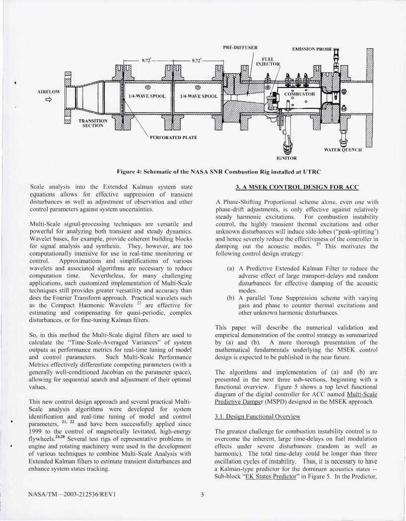
Figure 4: Schematic of the NASA SNR Combustion rug installed at UTRC
Scale analysis into the Extended Kalman system state equations allows for effective suppression of transient disturbances as well as adjustment of observation and other control parameters against system uncertainties.
Multi-Scale signal-processing teclmiques are versatile and powerful for analyzing both transient and steady dynamics. Wavelet bases, for example, provide coherent building blocks for signal analysis and synthesis. They, however, are too computationally intensive for use in real-time monitoring or control. Approx imations and simplifications of various wavelets and associated algorithms are necessary to reduce computation time. evertheless, for many challenging application , such customized implementation of Multi-Scale techniques still provides greater versatility and accuracy than does the Fourier Transform approach. Practical wavelets such as the Compact Hamlonic Wavelets 22 are effective for estimating and compensating for quasi-periodic, complex disturbances, or for fine-tuning Kalman filters.
So, in this method the Multi-Scale digital filters are used to ca lculate the "Time-Scale-Averaged Variances" of system outputs a performance metrics for real-time tuning of model and control parameters. Such Multi-Scale Perfonnance Metrics effectively differentiate competing parameters (with a generally well-conditioned Jacobian on the parameter space), allowing for sequentia l search and adjustment of their optimal values.
Th is new control design approach and several practical MultiScale analysis algorithms were developed for system identification and real-time tuning of model and contro l parameters, 21 , 22 and have been successfully applied since 1999 to the control of magnetically levitated, high-energy flywheels. 24
,28 Several test rigs of representative problems in engine and rotating machinery were used in the development of various teclmiques to combine Multi-Scale Analysis with Extended Kalman filters to e timate transient disturbances and enhance system states tracking.
ASAJTM- 2003-212536/REV 1 3
3. A MSEK CONTROL DESIGN FOR ACC
A Phase-Shifting Proportional scheme alone, even one with phase-drift adjustments, is only effective against relatively steady hamlonic excitations. For combustion instability control, the highly transient thermal excitations and other unknown distmbances wi ll induce side-lobes ("peak-splitting ') and hence severely reduce the effectiveness of the controller in damping out the acoustic modes. 27 This motivates the following control design strategy:
(a) A Predictive Extended Kalman Filter to reduce the adverse effect of large transport-delays and random disturbances for effective damping of the acoustic modes.
(b) A parallel Tone Suppression scheme with varying gain and pha e to counter thellllal excitations and other unknown harmonic disturbances.
This paper will describe the numerical va lidation and empirical demonstration of the control strategy as summarized by (a) and (b). A more thorough presentation of the mathematical fundamentals underlying the MSEK control design is expected to be published in the near future .
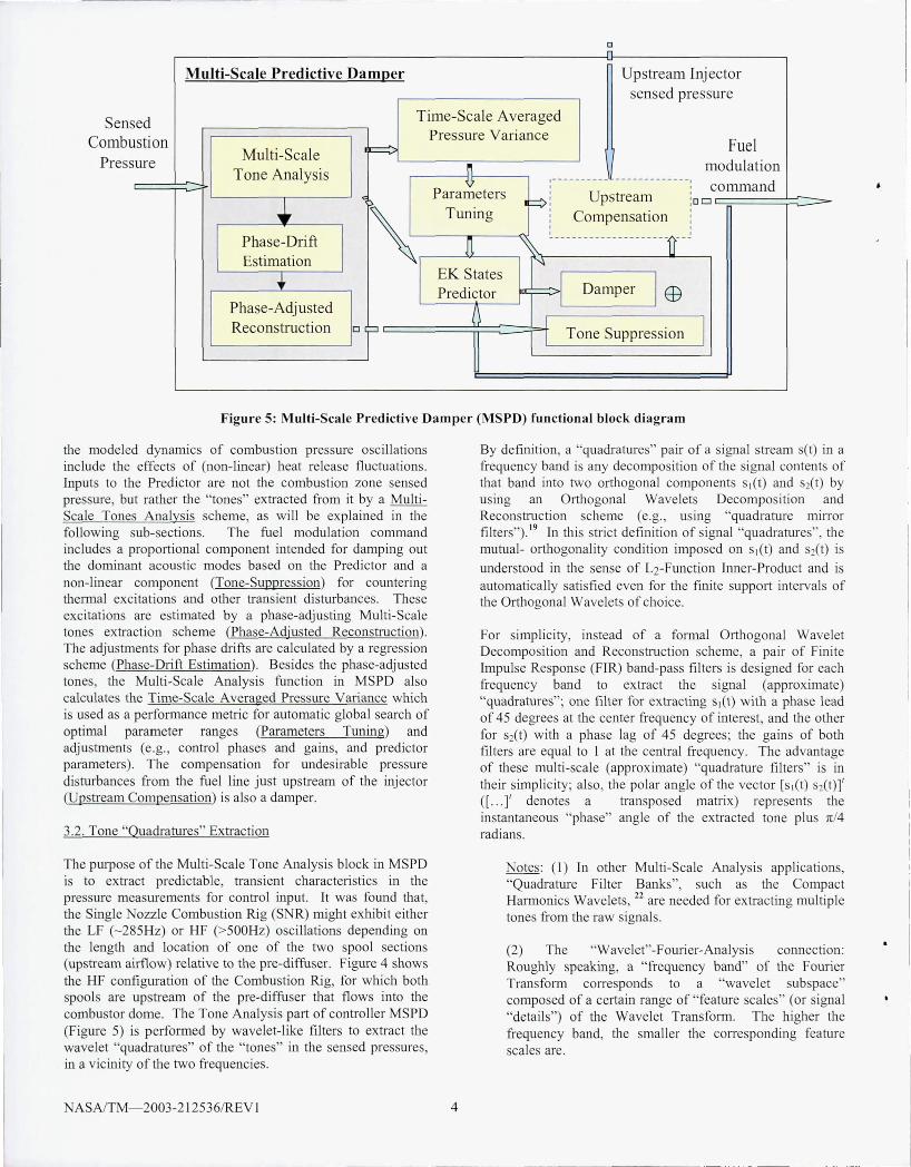
The algorithm and implementation of (a) and (b) are presented in the next three sub-sections, beginning with a functional overview. Figure 5 shows a top level functional diagram of the digital contro ll er for ACC named Multi-Scale Predictive Damper (MSPD) designed in the MSEK approach.
3.l. Design Functional Ovelview
The greatest challenge for combustion instability control is to overcome the inherent, large time-delays on fuel modulation effects under severe disturbances (random as well as hannonic). The total time-delay could be longer than three oscillation cycles of instability. Thus, it is necessary to have a Kalman-type predictor for the dominant acoustics states -Sub-block "EK States Predictor" in Figme 5. In the Predictor,
o n
Multi-Scale Predictive DamI!er Upstream Injector sensed pressure
Sens Combu
Press
ed Time-Scale Averaged
stion Pressure Variance Fuel
Multi-Scale I· ~ ure
Tone Analysis n modulation
< I ,---------- ------------
command , Parameters F>l Upstream ==-J, DO
~ Tuning , Compensation , ,
Phase-Drift J1 ~--------------------1J--
Estimation 'f ... EK States rr, I EB Predictor Damper Phase-Adjusted
t~ Reconstruction ~ I 0
I Tone Suppression
Figure 5: Multi-Sca le Predictive Damper (MSPD) fun ctional block diagra m
the modeled dynamics of combustion pressW"e oscillations include the effects of (non-linear) heat release fluctuations. Inputs to the Predictor are not the combustion zone sensed pressure, but rather the " tones" extracted from it by a MultiScale Tones Analys is scheme, as w ill be explained in the following sub-sections. The fuel modulation command includes a proportional component intended for damping out the dominant acoustic modes based on the Predictor and a non-linear component (Tone-Suppress ion) for countering thermal excitations and other transient di sturbances. These excitations are estimated by a phase-adjusting Multi-Scale tones extraction scheme (Phase-Adjusted Reconstruction). The adjustments for phase dr;fts are calcul ated by a regression scheme (Phase-Drift Estimation) . Besides the phase-adjusted tones, the Multi-Scale Analysis function in MSPD also calculates the Time-Scale Averaged Pressure Variance which is used as a performance metric for automatic global search of optimal parameter ranges (Parameters Tuning) and adjustments (e .g., contro l phases and ga ins, and predictor parameters). The compensation for undesirable pressure distUTbances from the fuel line just upstream of the injector (Upstream Compensation) is also a damper.
3.2. Tone "QuadratUTes" Extraction
The purpose of the Multi-Scale Tone Analysis block in MSPD is to extract predictable, transient characteri stics in the pressW"e measurements for control input. It was found that, the Single Nozz le Combustion Rig (S R) might exhibit either the LF (- 285Hz) or HF (>500Hz) oscillations depending on the length and location of one of the two spool sections (upstream airflow) relative to the pre-diffu er. Figure 4 shows the HF configW"ation of the Combustion Rig, for which both spools are upstream of the pre-diffuser that flows into the combustor dome. The Tone Analysis part of controller MSPD (FigW"e 5) is performed by wavelet-like filters to extract the wavelet "quadratUTes" of the "tones" in the sensed pressures, in a vicini ty of the two frequencies.
ASAJTM- 2003-212536/REV 1 4
By definition, a "quadr'atures" pair of a signa l stream set) in a frequency band is allY decomposition of the signal contents of that band into two orthogonal components Sl(t) and 2(t) by using an Orthogonal Wavelets Decomposition and Reconstruction scheme (e.g., using "quadrature minor filters,,). 19 In this strict defini tion of signal "quadratures", the mutual- orthogonali ty condition imposed on Sl(t) and S2(t) is
understood in the sense of L2-Function inner-Product and is automatical ly satisfied even for the fi nite support intervals of the Orthogonal Wavelets of choice.
For simplicity, instead of a fOlmal Orthogonal Wavelet Decomposition and Reconstruction scheme, a pair of Finite Impulse Response (FIR) band-pass filters is designed for each frequency band to extract the signal (approximate) "quadratUTes"; one filter for extracting Sl(t) with a phase lead of 45 degrees at the center frequency of interest, and the other for S2(t) with a phase lag of 45 degrees; the gains of both fi lters are equal to I at the central frequency. The advantage of these multi -sca le (approx imate) "quadr'ature filters" is in their simplicity; also, the polar angle of the vector [S l(t) S2(t)]' ([ ... ]' denotes a transposed matrix) represents the instantaneous "phase" ang le of the extracted tone plus n/4 radians.
otes: (l) In other Multi -Scale Analysis applications, "Quadrature Filter Banks", such as the Compact Harmonics Wavelets, 22 are needed for extracting multiple tones from the raw signals.
(2) The "Wavelet"-Fourier-Analysis C01ll1ection: Roughly speaking, a "frequency band" of the Fourier Transfolm corresponds to a "wavelet subspace" composed of a certain range of "featW"e scales" (or signal "details") of the Wavelet Transform. The higher the frequency band, the smaller the corresponding feature scales are.
3.3. Quadratures Prediction
Throughout this paper, Sn denotes the 4x I vector of the
"quadrature pairs" S" =[S;] of tone I and tone 2 extracted s"
from the sensed combustor chamber pressure oscillations (LF and HF tones, respectively; with the superscript as the tone index and "/7" as the time index). The following approximate "evolution model" (Equations (I-a) to (I-f) for tbe combustion pressure quadratures at N sampling steps (control-delay time) ahead of the "current" time index "n" was used for the formulation of the predictor (See Appendix: Predicted Quadratures Evolution Model):
SN+ n+ 1 = PSN+n + Q + w
Zn+ 1= U Zn + FM SN+n
Yn =Ezn +DMSN+n+v
[PI ]= [hi 1 0 bl2 O]S + [bJu P2 h 2 I 0 h 22 0 n b n
witb limits: -p :=; p. :=; p max I max
Q; =K [ (Ph} -1) (fm i = 1, 2)
0=[0 0 1 0 O2 ]1
(I-a)
(I-b)
(I-c)
(I-d)
(I-e)
(l-f)
The "output measurement" in these equations is a 2x I vector y" representing the combined quadratures of mode I and mode 2 extracted from combustor pressure measurement at time index "n" for input to the Kalman predictor. That is,
y =:MSn n
M = [I 0 I Ol o I 0 IJ
(2-a)
(2-b)
The large time-index shift from S N+n to the feedback Yn was approximated by a 5th-order Pade approximation. That is, in
Equations (l-b) and (I-c), Yn was viewed as the result of a sth_
order Pade-transform (for a time-delay - N xT; T denotes the
sampling time) applied on the 2x I vector M S N+n. So, U, F, E, D are just the combined state matrices of the pair of Padetransformations used (witb the respective dimensions lOx 10, IOx2, 2x 10, and 2x2). The quantities v and ware bandlimited random vectors.
[
[COs(~ T) -sin(wl T)] 0 1 I A, sm(wlT) cos(~ T)
A= [ 0 1 [COs(~ T) -sin(w2 T)]
~ sin(cq T) cos~ T)
(3)
with T being the sampling time; lV, , co;. (in radians/sec) are the two tone frequencies ; ( J , ( 2 their open-loop damping
ASAlTM- 2003-212536/REV I 5
coefficients; and A, =exp (-2( ,lV, T); ~=exp (-2( 2 CO;. T ). The effect of combustion beat fluctuations on these acoustic quadratures (at N steps ahead of /7) is approximated by the
vector-valued function Q of Sn and the fuel modulation
command Un, as formulated in (I-d) to (I-f). The parameters
{ hi j J are constant, internal feedback gains; b the
approximate control authority; Po, a reference pressure
comparable to tbe mean pressure drop across the injector. The
parameters { hi j } , b, K , p max , and N are chosen to match
tbe open-loop forced response characteristics of the combustion chamber pressure.
The Kalman Quadratures Predictor: Equations (1-a) to (I-f)
result in an estimation for S N+n, denoted by S n ' formulated
explicitly in Equations (4-a) to (4-e) below:
~+ I =AS n + Q +K,(EZn +DMS n-MS n) (4-a)
Zn +,=UZn +FMS n +K2(EZn +DMS n - MS n) (4-b)
(4-c)
with limits: - p :=; p. :::; p max I max
Q;=K [ rh} -1) (fo, i = 1, 2) (4-d)
0=[0 0 1 0 O 2 ]1 (4-e)
The matrices K, and K2 (of dimension 4x2 and IOx2, respectively) are the two vertical sub-blocks of the Kalman matrix computed from the evolution equations (1-a) to (I-c) for certain covariance matrices assumed for tbe random vectors v and w in these equations, treating Q as a known input at time " /7" . ote that, in tbis simplified estimator for
S N+n, the Kalman innovation term'S was omitted. The numerical values of the parameters in Equations (4-a) to (4-e) will be presented in Section 4.
3.4. Phase Bias and Drift Correction with Quadratures
If 5 == [sICt) ~(J)] I is the vector of quadratures ex'tracted from
a signal set) using "Quadrature Fi lters", then a combination
~ == (Sl(t)cosa-~{J)sim) represents the tone of set) in tbe
Quadrature bandwidth phase-shifted by "a+nl4" radians. Thus, it might be used in a Proportional Phase-Shifting control scheme for a suitable phase bias "a ". But, a Proportional Phase-Sbifting control with a fixed pbase bias is not effective in handling large time-delays and phase drifts of transient or time-varying dynamics, especially when the Signal-to-Noise
ratio is small. To remedy this, a regression scheme was used to estimate the drifts in the accumulated phase of each tone over the expected time interval of the total transport-delay.
3.5. Damper Command
A part of the fuel-modulation command U n, essentially an LQR damper (distinguished by the superscript cd' ) of fixed gain, is formulated as:
(5)
~ I ~2
where S /1, (t n) and S /12 (t n) are the signals constructed
from each of the predicted quadratures as 2x I sub-blocks in
8" ==[~l ' using respective phase angles fJi == /3+5 ; n (for S"
-the tone indices i = I , 2), where fJ is a fixed bias , 5 ; n the
predicted phase-drift. The quantities Jl I and Jl2 are fixed gains.
The drifts 5 ; n (over the time interval of expected control
transport-delay, for tones i = 1, 2) are predicted by a
regression scheme applied on the quadrature phases {ex ; n } as
defmed in Equation (6) of the next sub-section.
3.6. Suppressions of Residua l Harmonic Disturbances
This part of the control scheme is to cancel out remaining harmonic disturbances that can not be suppressed by just the "damper". For this purpose, the instantaneous amplitudes and phases of the combustion pressure near the LF and HF are first
estimated by projecting the quadratures S:, (for i = I , 2, as
2x 1 vectors) onto an orthogonal frame rotating at the
respective speed lllj . To reduce the effect of random noises, these projections are next passed through low-pass fi lters with cut-off frequencies at 100 Hz and 200 Hz, respectively, before computing the amplitudes and phases. Note that these cut-off frequencies are about 1/3 of the respective central frequencies. Consequently, the predicted pressure oscillations for the respective frequency bands are given by:
(for i= 1, 2) (6)
where (i n is the amplitude, and {a ; n } the polar angle at time
tn of the filtered, projected quadrature vector.
Note that, (J"; should be highly coherent with the unknown
" residual" harmon ic excitations other than white-noise disturbances and the heat quantities associated with expression (J -t)o Therefore, to cOLmter this unknown effect the fuel-
modulation command u" is augmented with a compensation term (distinguished by the superscript 'c ') of the following form, as computed in Tone Suppression:
ASAlTM- 2003-212536/REVI 6
u~' = L Yi nri nCOS({1);I,, +a ;n+ a+6" ;n) ;= 1,2
(7)
(for tones i = I , 2), where Yin is an varying gain applied on
(J ; after it is phase-shifted by a bias a plus 6" ; n' These
gains are calculated as di screte values of this express ion:
(for i=I , 2) • (8)
where Yo is a constant gain compatible to the expected control
authority; 17 , a constant integral gain; Pi , a reduction level
expected to be maintainable for r i with this scheme. Also, Yo's are limited between certain bounds Ymin and Ymax before substituted into Equation (7).
3.7. Fuel Modulation Command and Tuning
Finally, expressions (5) and '(7) combined gives the fuelmodulation command:
(9)
In this control scheme, all the parameters in the predictor (as well as the control scheme) appear to be fairly deterministic and empirically predictable (at least for the S R case), except
for the phase biases, ex and fJ , and the control authority
represented by "b" (see Equations (I -d)). These parameters are set by the Parameters Tuning logic in sequential globa l searches at low loop-gain . Once found, the average phase biases are adjusted with a slow-varying adjustment term E.
Such setting and adjustment of control variables are based on minimizing the Time-Scale Averaged Pressure Variance, defined for this controller to be a 0.2-Hz low-pass version of
the square-norm of S".
Note: The pressure perturbations just upstream of the injector are highly correlated with the combustion pressure. So, they can be used as add itional feedback to provide more active damping to the acoustic modes either inside the combustion zone or in the fue l-line. This can be done with a predictive damper as in the calculation
of U~d ' . Such dynamic equations for the predictor are far
from being a physical model of tbe fuel-line dynamics. But, the actual correlation of the fuel-line with the combustion zone dynamics should nevertheless be adequately retained in the predicted states by virtue of the Kalman gain matrix .
4. DESIGN EVALUATION AND EXPERIMENT
The ASA Single Nozzle Combustor Rig (S R) at UTRC was used as the experimental test bed for demonstrating closed-loop instability suppression using the MSPD controller. The SNR was operated at a pressure, temperature, and fuel-air ratio corresponding to a mid-power engine condition
•
(T3=770°F, P3=200psia, fuel-air ratio=0.03) and exhibited roughly the instability behavior shown in Figure 2.
4.1. Simulation Models
A reduced-order, parametric model and a "Sectored-I D" thermo dynamics flow model (Paxson 25) of the SNR were used in the design and evaluation of the MSPD controller. The former is essentially a Helmholtz-type model of the two the11110-acoustics modes of the SNR, f01111ulated in quadrature state variables similar to Equation (I-a) to (I-f) as follow:
'ac' s" = P" + v"
with limits : - p ~ Pi ~ P max max
Q; =K[ (Ph} -1) (fo, i= 1, 2)
Q =[O Q , 0 Q2 ]t
(lO-a)
(lO-b)
( lO-c)
(lO-d)
(lO-e)
(l0-f)
In equations (lO-a) to (l0-f), the state matrix A is as in expression (3) . And,
X I I 2 2 t 11 == [x x x X ] stands for the 4x I state vector
In 2n In 2n
'oc' of mode 1 and 2 (as superscripts); Pn the static pressure
oscillation about the mean static pressure p (of the operating 'ac'
condition in the combustion zone); s" , sensed Pn ; and
w" , v" are scalar, white disturbance and sensor nOlse
limited to below 2000Hz. The heat-release fluctuation effect Q is a vector-valued function of delayed states, fuel
modulation conIDland, Un ' including valve dynamics, and
disturbances. The operators 'fa' 'fb , 'fc are random time
shifts (with non-zero mean values) applied on the respective variables. The effect of the combustion zone pressure oscillation on fuel modulation is too complex to model
. . 'ac' . accurately; so, the terms mvolvmg Pn and the constant gam
"g " are used here only for testing the robustness of the controller, not to be included in the predictor equation.
Remark: This plant model presents all the main challenges of the SNR: the thermal excitations modeled
by the internal feedback matrix { hi j } , the time delay
N ASA/TM- 2003-212536IREV 1 7
'fb on control, phase drifts due to some randomness in
the delays, and disturbances ~
4.2. Control Validation Results
The followil1g parameter values of the reduced-order model for the HF-Configuration SNR are with PSI as the unit for the pressure feedback, Volt for the fuel-modu lation command Un
to the servo valve used -- which was limited to 2 Volts in amplitude.
First, the measurement gain and the internal feedback gain for the dominant mode (Equation (lO-b) and (lO-d), respectively) are both n01111alized so that:
With that nonnalization and units choice, the rest of model parameters are chosen to match empirical data for the sampling time T = 0.0002 seconds (i.e.; 5000 Hz VO rate are used for both the reduced-order model and controller outputs on the rig):
C II = 0.8
Po =20 ; K=0.6Po=12
b \I = I ; h, 2 = h 2 I = 0.1 ;
fa =0.0038; fb =0.0033; fc =0.0002 (mean values);
b =0.2322; g =0.01 ;
The nTIS value of~, is 0.2805 for the high disturbance
setting, and is 0.07 for low disturbance; that of v" is 0.07.
The effect of fuel valve on the command Un is represented by
a low-pass filter (resulting in U n ) and an attenuation which is
already absorbed into b.
The damping parameters C in the predictor (Equation (4-a) to (4-e)) and in Equations (I-a) to ( I-c) for the Kalman matrix calculation were deliberately set at 30% of critical damping for both modes, not at the estimated values which is only about 0.03 for the HF mode. This is to ensure stability for the predictor with a simplified implementation of the Kalman feedback.
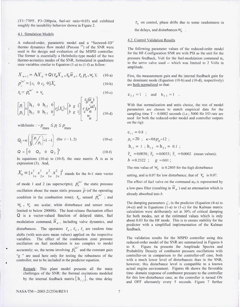
The validation results for the MSPD controller using this reduced-order model of the SNR are SUl1IDlarized in Figures 6 to 8. Figure 6a presents the Amplitude Spectra and Probability Density of combustor pressure oscillations with controller-on in comparison to the controller-off case, both with a much lower leve l of disturbances than in the SNR; however, this disturbance level is compatible to a known actual engine environment. Figures 6b shows the favorable time- domain response of combustor pressure to the controller for this low-disturbance case, as the controller is turned ON and OFF alternately every 5 seconds. Figure 7 further
06
05
, 5
05
o -'5
AlrC>iI_ St>edrun - MSEK ACC ~rrUa.oo., tow random ciS06bon<es
()pet>looI> (WIth low random clshnnceS)
c - ............... ~ .............. . 300 ' 00 500 600 700 600 900 1000
Fr~ in Hz (Rill WIth TNnO-delty =: 0 0015 )
- Closed-loop
- - -'--- ~-- -., .os 0 05 1 , S PrtsSU'e In PSI (Probabkly Density OiSlntMAJon)
(a): Closed-loop versus open-loop combustion pressure oscillation Amplitude-Spectrum and Probability Density
MSEK ACe sunJetfon at b-N random distOO)ances (Ccwtrol Or-OOFF)
. , 5 0 05 , 5 25 35 '5
TIme (seconds)
~2 ~ 1
L I ~ ~2
-3 ' 0 05 ,5 35
(b) : Pressure oscillations (top) and commands 0 /OFF (bottom)
Figure 6: Simu lation results with the reduced-order model at low random disturbance
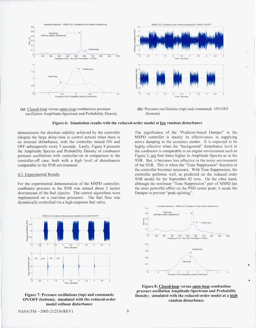
demonstrates the abso lu te stability achieved by the controller (despite the large delay-time in contro l action) when there is no external disturbance, with the controller tumed ON and OFF subsequently every 5 seconds. Lastly, Figure 8 presents the Amplitude Spectra and Probability Density of combustor pressure oscillations with controller-on in compalison to the controller-off case, both with a high level of disturbances comparable to the SNR environment.
4.3. Expelimental Results
For the experimenta l demonstration of the MSPD contro ller, combustor pressure in the S R was sensed about 2 inches downstream of the fuel injector. The control algorithms were implemented on a real-time processor. The fuel flow was dynamically contro lled via a high-response fuel valve.
-20 - -=0'="'5- -:-- -:":-5 ~~:----::':~5:- -;- 35 T.rne (WCcnH)
Figure 7: Pressure oscillations (top) and commands ON/OFF (bottom); simulated with the reduced-order
model without disturbance
ASNTM- 2003-212536/REVl 8
The significance of the "Predictor-based Damper" in the MSPD controller is mainly its effectiveness in upplying active damping to the acoustics modes. It is expected to be highly effective when the "background" disturbance level in the combustor is comparable to an engine environment such as Figure 2, not four times higher in Amplitude Spectra as in the S R. But, it becomes less effective in the noisy environment of the S R. This is when the "Tone Suppression" hmction in the control ler becomes necessary. With Tone Suppression, the contro ll er perfomls well, as predicted on the reduced order S R model for the September 02 tests. On the other hand, although the non linear "Tone Suppression" part of MSPD has the most powerful effect on the PSD center peak, it needs the Damper to prevent "peak-splitting" .
~Ol f &? 02 t
01 1 """"'-.... ,..~ [ ..-- ----."
I - ./' O~~~,00~~200~~lOO~~.OO~~~~-=sOo~-=700~---aoo~-~-~~~~,~~
F reqJenCy In Hz (Rill 'Mth Time-deIIy • 0 0035 )
O.
06
O'
02
O --~ -=-----4 ·3 ·2 ., 0 1 2 3
PresSU'e In PSI (Probebiky DensdY OIstribcAion)
Figure 8: Closed-loop versus open-loop combustion pressure oscillation Amplitude-Spectrum and Probability
Density; simulated with the reduced-order model at a high random disturbance
•
•
•
•
•
'rI c. cO ii Q)
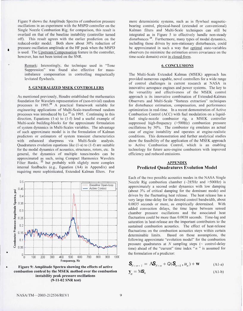
Figure 9 shows the Amplitude Spectra of combustion pressure oscillations in an experiment with the MSPD contro ller on the Single Nozzle Combustion Rig; for comparison, this result is overl aid on that of the baseline instabili ty (controller turned off). This result agrees with the earlier predi ction on the reduced-order model. Both show about 30% reduction of pressure oscillati on amplitude at the HF peak when the MSPD is used. The Upstream Compensation feature in the contro ller, however, has not been tested on the S R.
Remark: Interestingly, the technique used in "Tone Suppression" was found also effective for massimbalance compensation in contro lling magnetica lly lev itated fl ywheels.
5. GENERALlZED MSEK CONTROLLERS
As mentioned previously, Houdre establ ished the mathematics foundation for Wavelets representation of (non-trivial) random processes in 1993.20 A practical framework suitable fo r engineering applications of Multi-Scale-transfomled random processes was introduced by Le 2 1 in 1995. Continuing in this direction, Equations (I-a) to (l -f) lend a useful example of Mul ti-scale building-blocks for the approx imate formulation of system dynamics in Multi-Scales vrui ables. The advantage of such approx imate model is in the f01111ulation of Kalman predictors or estim ators of system transient characteristics with enhanced shru-pness via Multi-Scale analysis. Quadratures evolution equations like ( I-a) to ( l-f) are sui table for the modal dynamics of acoustics, structures, rotors, etc. In genera l, the dynamics of multiple tones/modes can be approx imated as such, using Compact Hamlonics Wavelets Filter Banks, 22 but probably with s lightly more complex internal feedbacks (e.g. , Equation (A4) in Appendix) and requi ring more sophisticated, Extended Kalman fi lters. For
0.5
0.45
0.4
, , , - - - - - -T - - - ---.,- - - - ---,-- - - - --,.. --- --- T - - -- - -.,
.... .. Baseline Open-loop - Active Control
: : : : : : ~~--~~--~~ , , , , , I , I , ;. I , I ,
- - - - - - t - -- - - -.;- - - - - --:- - - - - - -:- - - - - - - f - ~- - - - ~ - - - - - - -;- - - - - - -:- - - - - - -; - - - --
: : : : : £~ : : : : ~ 0.35 --- ---: ------~ ------.:. ---- - - ~ ------: - ~ ~ -- -~ ------~- ---- --~ ------~ -----
~ l 1 ~ ~ ;= :i ~ , ~ ~ Q)
~ 0.3 c. E
0.25 c:(
, , , , ' :. , , , , -- ---: --- ---~ ---- ---;--- ----:--- ---: r -r-: ------ :------ -: -- ----~- ----: , : : : j ~ : : : , -- ---! --- -- -; ---- ---:- --- ---;- ---- - T - : --;- - - - -- ;-- - - -- -;--- -- - - ~ - ----
~ iii 0.2 ~
Cl. 0.15 . ....
0
I I I I : I , , I
: : :: : :::: __ _ _ __ 1 __ ____ J ______ _ , _ ______ \0. _____ _ _ _ _ :.. _ J ____ __ J _ _ ____ _ \0. ______ L _ ___ _
, , " • ~ , , , I
: : :.:"::: : , '! __ __ l i ______ L ______ .. ___ ___ ~ ____ _
: ' : : : ~ 0.1 ..,
, , , , , ,
E 0 u 0.05
0 0 100 200 300 400 500 600 700 800 900 100C
Frequency, Hz
Figure 9: Amplitude Spectra showing the effects of active combustion control by the MSEK method over the combustion
instability peak pressure oscillations (9-11-02 SNR test)
NASAlTM- 2003-212536/REV l 9
more deterministic systems, such as in flywheel magneticbearing control, physical-based (extended or conventiona l) Kalman fil ters and Multi-Scale techniques can still be integrated as in Figure 5 to effectively handle non-steady disturbances 24 . Furthermore, many types of modal dynamics, including those driven by non-stat ionary disturbances, could be approximated in such a way that optimal tate-variables observers (to mi nimize the estimation eITors covari ance on the tim e-scale domain) ex ist in closed-foml .
6. CONCLUSIONS
The Multi-Scale Extended Kalman (MSEK) approach has provided numerous capable, novel contro llers for a wide range of contro l challenges in CUITent research at ASA in innovative aerospace engines and power systems. The key to the versatility and effectiveness of the MSEK contro l approach is its ilillovative combi nation of Extended-Kalman Observers and Mul ti-Scale "features extraction" techniques for di stw'bance estimation, compensation, and performance optimization in real-time. In a recent demonstration of Active Combustion Contro l (ACe) with fue l modulati on on a liqu idfu el single-nozzle combustor rig, a MSEK controller suppressed high-frequency (>500Hz) combustion pressure oscillations by 30%. The combustor ri g emulates an actua l case of engine instabili ty and operates at engine-real istic condi tions. This demonstration and further analytica l studies show the feasibi lity of the appl ication of the MSEK approach to Acti ve Combu tion Contro l, which is an enabl ing technology for futw'e aero-engine combustors with improved efficiency and reduced emissions.
APPENDIX
Predicted Quadratures Evolution Model
Each of the two possible acoustics modes in the ASA Single Nozzle Rig combustion chamber (- 285Hz and >500Hz) is approx imately a second order dynamics with low damping (about 3% of critica l damping for the dominant mode) and dri ven by the fluctuating heat release. The heat release has a very large time-delay for the desired contro l bandwidth, about 0.0035 seconds or more, as empirica lly detemlined. With added convection delays, the time lapse between sensed chamber pressure oscillations and the associated heat fl uctuation could be more than 0.0038 seconds. Time- lag and saturation in heat-release are the important contributors to the sustained combustion acoustics. The effect of heat-release fluctuati ons on the combustion acoustics stays within certain determinable limits. Based on those assumptions, the fo llowing approximate "evolution model" for the combustion pressure quadratures at N sampling steps (- contro l-delay time) ahead of the "cuITent" time index" n " is assumed for
the formulation of a predi ctor:
(A I -a)
(A I-b)
In Equation (AI -a) and (A I-b), S n denotes the 4xl vector of
S _=[Sl~] the "quadrature pairs" of tone 1 and tone 2 /1 S2
II
(~285Hz and >500Hz, respectively); the superscript is the tone index and " n " is the time index.
(Note: For simplicity, instead of a formal Orthogonal Wavelet Decomposition and Reconstruction scheme, a pair of Finite Impulse Response (FIR) band-pass filters can be suitably designed for each frequency band to extract the signal approximate "quadratures": One filter with a phase lead of 45 degrees at the center frequency of interest, and the other with a phase lag of 45 degrees; the gains of both filters are equal to j
at the central frequency. The advantage of these "Quadrature Filters" is in the ir simplicity. The polar angle of the vector of extracted quadratuxes [Sl(t) S2(t)]' by such filters represents the instantaneous " phase" angle of a tone plus 11:/4 radians -- [ ... ]' denotes a transposed matrix.)
The "output measurement" in Equation (A I-b) is a 2x l vector y representing the combined quadratures of mode j and
n mode 2 extracted from the sensed combustor pressure at ti me index "n". So:
M = [I 0 1 Ol o 1 0 IJ
(A2)
The quanti ties W is a band-limited random vector. The 4x4
"state-matrix" A in Equation (AI-a) represents only the dynamics of combustion chamber acoustics in modal representation, not including thermal excitations. Explicitly,
[COS(UJ T) -s in 0J1 T)]
A = A, sin(cvIT) cos(UJT)
[ 0 1
[ 0 1
[CoS(~ T) -sin(cv2 T)]
Az s in(~ T) cos~ T)
with T = 0.0002 seconds, the sampling time; and,
(A3)
COl = 570 7r radians/sec; S 1 = 0.30; A, = exp (-2 s I COl T ).
CO:!. > 1000 7r radians/sec; S2 = 0.03 ; Az = exp (-2s 2 CO:!. T ).
The effect of combustion heat fluctuations on these acoustic quadratures (at N steps ahead of n) is modeled as a certain vector-valued function Q of the earlier acoustic states denoted
by Sk+ II and the fuel modulation command UII (with k being a fixed integer much smaller than N). This vector-valued function is assumed of the fOID1:
(A4)
where the time-varying entries on the rhs are calculated using the following express ions of "effective modal excitations"
PI and P2 on fuel-flow variations and the acoustic states at
time "N+n" ·
ASAlTM- 2003-21 2536/REV 1 10
[PI ]_ [hi I 0 hi 2 0Js [b] P2 = h 2 I 0 h 22 0 n+ k + bUn '
(AS)
where {h i j } are constant, internal feedback ga ins, b the
approx imate control gain . Also, P i 'S (for i=1 , 2) are
subj ected to:
- Pmax :;: P i :;: P max (for i = 1 , 2) , (A6)
for a certain upper bowld denoted P max ' The respecti ve
unsteady heat effect Qi assoc iated with these quanti ties Pi
(for i = 1,2) are then approximated by:
(A7)
In Equation (A 7), Po is a reference pressure comparable to the
mean pressure drop across the I11J ector. The
parameters { h i j } , b, K , p max , and N are chosen to match
the open-loop forced response characteli stics of the combustion chamber pressure.
Since k (in Equations (A4) to (A 7» is small relative to N, it can be set to zero, so that Q would be treated as a known input
at time n. But, the large time-index shift from S N+" to the
feedback y" is approximated by a 5th-order Pade
approximation. That is, Yn is viewed as the result of a 5th_
order Pade-transfornl (for a time-delay - N xT , T = 0.0002
second) applied on the 2x I vector MSN+". Consequently, instead of Equation (A I-b) the following state-space
relationship between of S N + " and Yn should be used with
(AI-a) to derive a Kalman "estimator" (predictor) for S N+n:
Z" + 1= U Z" + FM S N+"
y" = EZn + DM S N+ n+V (A8)
where V is a band-limited random vector; and U, F, E, D are the combined state matrices of the pa ir of Padetransfonnations (with the respective dimensions l Ox 10, IO x2, 2x 10, and 2x2).
•
•
•
REFERENCES
[I] Lefebvre, A.H.: Gas Turbine Combustion, 2nd edition, Taylor & Francis, 1999. [2] Brower, J ., Ault, B. A. , Bobrow, J. E., and Sumuelsen, G. S. , 1990: "Active Control for gas Turbine combustors," the 23rd International Symposium on Combustion, the Combustion institute, Pittsburgh. [3] Schadow, K. , Yang, V. , Culick, F., Rosfjord, T. , Sturgess, G., and Zinn, B.: "Active Combustion Control for Propulsion Systems," AGARD Report 820, September 1997. [4] Yu, K. , Wilson, KJ. , and Schadow, K.e.: "Active Combustion Control in a Liquid-Fueled Dump Combustor," AlAA Paper 97-0462, January 1997. [5] Zinn, B.T. and eumeier, Y.: "An Overview of Active Control of Combustion Instabilities," AIAA Paper 97-0461 , January 1997. [6] McManus, K.R. Magill , le., Miiller, M.F., and Allen, M .G.: "Closed-Loop System for Stability Control In Gas Turbine Combustors," AIAA Paper 97-0463 , January 1997. [7] Annaswamy, A.M. , El Rifai , O.M., Fleifil , M ., Hathout, J.P., and Ghoniem, A.F.: "A Model-based Self-tuning Controller for Thermoacoustic Instability," in Combustion Science and Tech. , Vo1135 , pp. 213-240, 1998. [8] Whitelaw, J.H. : Combustion Oscillations, Extinction, and Control, final technical report, U.S. Army contract N68171-97-C-9035, May 1998. [9] Hibshman, J.R. , Cohen J.M. , Banaszuk, A., Anderson, T.J. , and Alholm, H.A.: "Active Control of Combustion instability in a Liquid-Fueled Sector Combustor," presented at the international Gas Turbine & Aero-Engine Congress and Exbibition, June 1999. ASME Paper 99-GT-215. [10] Allgood, D. , Campos-Delgado, D. U. , Acharya, S. , and Zhoo, K.: "Acoustic Control of Thermoacoustic Instabilities Using Experimental Model-Based Controllers," Proceedings of ASME Turbo Expo, New Orleans, LA, 2001. [II] Johnson , e. E. , Neumeier, Y., uemaier, M. , and Zinn, B. T .: "Demonstration of Active Control of Combustion Instabilities on a Full-Scale Gas Turbine Combustor," Proceedings of ASME Turbo Expo, New Orleans, LA, 200 I. [12] Murugappan, S. , Park, S., Acharya, S., Annaswamy, A. M. , Gutmark, E. J. , and Gboniem, A. F. , 2000: "Optimal Control of Swirl-Stabilized Combustor using System Identification Based Model," Turbine Conference, Cesme, Turkey. [13] Murugappan, S., Acharya, S. , Gutmark, E. J. , and Messina, T. , 1999: "Characteristics and Control of Combustion Instabilities in a Swirl-Stabilized Spray Combustor," tbe 35th Joint Propulsion Conference and Exhibit, Los Angeles, CA. [14] DeLaat, le., Breisacber, KJ ., Saus, lR. , Paxson, D.E. , 2000: "Active Combustion Control for Aircraft Gas Turbine Engines," 36th Joint Propulsion Conference and Exhibition, Huntsville, AL.
ASAlTM- 2003-212536/REV I II
[15] DeLaat, J. C. and Chang, e. T.: "Active Control of Higb Frequency Combustion Instability in Aircraft Gas-Turbine Engines," to be presented at tbe 16th International Symposium on Air breathing Engines, Cleveland, Ohio, August 31-September 5, 2003. [16] Coben, J.M . et al: "Experimental Replication of an Aeroengine Combustion instability," International Gas Turbine and Aero-Engine Congress and Exhibition, Municb, Gennany, 2000. [17] Kopasakis, G.: "High Frequency Adaptive Instability Suppression Controls in a liquid-Fueled combustor", proposed for presentation at the 39th Joint Propulsion Conference and Exhibit, Huntsville, Alabama, July 20-23 , 2003 . [J8] Jazwinski A. H ., Stochastic Processes and filtering
Theory, Mathematics in Science and Engineering Vol.64, Academic Press, 1970. [19] Meyer Y., 1991 , Wavelets: Algorithms and Applications, English translation and revision by Robert D. Ryan , SIAM edition 1994. [20] Houdre, e. , 1993, "Wavelets, probability, and statistics: Some bridges," Wa velets Mathematics and Applications (Studies in Advanced Mathematics), edited by J. J. Benedetto and Michael W. Frazier, GRC Press, 1994 edition. [21] Le, D. K. , "Multiscale System Identification and Estimation," Advanced Signal Processing Algorithm (1995) , ed. F. Luke, SPIE Proceedings, vol. 2563. [22] Le, D. K., Owen, A. K. , Simon, D. L. , 1997: "Wavelet Analysis of Air-Jet Injection Stall Control Effects in an AxiCentrifugal Gas Turbine Engine," AlAA paper 97-2774, 33 rd
Joint Propulsion Conference, July 6-9, Seattle, WA. [23] Misawa, E. A. and Hedrick, J. K.:" onlinear Observers - A State-of-the-Art Survey," Transaction of the ASME, Journal of Dynamic Systems, Measurement, and Control, Vol.lll, pp 344-352, September 1989. [24] Le, D. K. and Provenza, AJ.: "Tracking the PolarPrinciple Axis for Magnetic Bearing Control and Flywheel Balancing" ,Power Systems 2000 SAE Conference, 00PSC69 [25] Paxson , D.E. : "A Sectored-One-Dimensional Model for Simulating Combustion Instabilities in Premix Combustors," presented at the 38th AIAA Aerospace Sciences Meeting & Exhibit, Reno, evada, January 2000, ASA TM 1999-209771 , AIAA -2000-0313 . [26] Barooah, P., Anderson, T. J ., and Cohen, J. M.: "Active Combustion Instability Control with Spinning Valve Actuator," Proceedings of ASME Turbo Expo, Amsterdam,
etberlands, 2002. GT-2002-30042. [27] Annaswamy, A.M. and Ghoniem, A.F. : "Active Combustion Instability: Tbeory and Practice," IEEE Control Systems Magazine, December 2002, Vol. 22, Number 6. [28] Le, D. K. and Provenza, AJ.: "An Observer-Based Magnetic Bearing Controller for Aerospace Flywheels,"
ASA Glenn Research Center 2001 Research and Technology Report (NASA TM 2002-211333).
REPORT DOCUMENTATION PAGE Form Approved
OMB No. 0704-0188
Public reporting burden tor this collection of information is estimated to average 1 hour per response, including the time for reviewing instructions , searching existing data sources, gathering and maintaining the data needed, and completing and reviewing the collection of information. Send comments regarding this burden estimate or any other aspect of this collection of information, including suggestions for reducing this burden, to Washington Headquarters Services, Directorate for Information Operations and Reports, 1215 Jefferson Davis Highway, Suite 1204, Arlington, VA 22202-4302, and to the Office of Management and Budget, Paperwork Reduction Project (0704-0188), Washington, DC 20503.
1. AGENCY USE ONLY (Leave blank) 1
2.
REPORT DATE 13
. REPORT TYPE AND DATES COVERED
October 2003 Technical Memorandum 4. TITLE AND SUBTITLE 5. FUNDING NUMBERS
Control of Thermo-Acoustics Instabilities: The Multi-Scale Extended Kalman Approach
6. AUTHOR(S) vrBS-22-70S-2S-09
Dzu K. Le, John C. DeLaat, and Clarence T. Chang
7. PERFORMING ORGANIZATION NAME(S) AND ADDRESS(ES) 8. PERFORMING ORGANIZATION REPORT NUMBER
National Aeronautics and Space Administration John H. Glenn Research Center at Lewis Field E-14100-1 Cleveland, Ohio 44135-3191
9 . SPONSORINGIMONITORING AGENCY NAME(S) AND ADDRESS(ES) 10. SPONSORINGIMONITORING AGENCY REPORT NUMBER
National Aeronautics and Space Administration NASA TM-2003-212536-REV 1 Washington, DC 20546-0001 AIAA-2003-4934
11. SUPPLEMENTARY NOTES
Prepared for the 39th Joint Propulsion Conference and Exhibit cosponsored by the AIAA, AS ME, SAE, and ASEE, Huntsville, Alabama, July 20-23, 2003. Responsible person, Dzu K. Le, organization code 7760,216-433-5640.
12a. DISTRIBUTION/AVAILABILITY STATEMENT 12b. DISTRIBUTION CODE
Unclassified - Unlimited Subject Category: 07 Distribution: Nonstandard
Available electronically at http://gltrS.grc.nasa.gov
This publication is available from the NASA Center for AeroSpace Information, 301--{)21-O390. 13. ABSTRACT (Maximum 200 words)
Multi-Scale Extended Kalman (MSEK) is a novel model-based control approach recently found to be effective for suppressing combustion instabilities in gas turbines. A control law formulated in this approach for fuel modulation demonstrated steady suppression of a high-frequency combustion instability (>SOOHz) in a liquid-fuel combustion test rig under engine-realistic conditions. To makeup for severe transport-delays on control effect, the MSEK controller combines a "wavelet"-like "Multi-Scale" analysis and an "Extended Kalman Observer" to predict the thermo-acoustic states of combustion pressure perturbations. The commanded fuel modulation is composed of a damper action based on the predicted states, and a tones suppression action based on the Multi-Scale estimation of thermal excitations and other transient disturbances. The controller performs automatic adjustments of the gain and phase of these actions to mini-mize the Time-Scale Averaged Variances of the pressures inside the combustion zone and upstream of the injector. The successful demonstration of Active Combustion Control with this MSEK controller completed an important NASA milestone for the current research in advanced combustion technologies.
14. SUBJECT TERMS 15. NUMBER OF PAGES
Active combustion control; Aircraft engines; Control; Combustion stability 16. l7
PRICE CODE
17. SECURITY CLASSIFICATION 18. SECURITY CLASSIFICATION 19. SECURITY CLASSIFICATION 20. LIMITATION OF ABSTRACT OF REPORT OFTHIS PAGE OF ABSTRACT
Unclassified Unclassified Unclassified
NSN 7540-01-280-5500 Standard Form 298 (Rev. 2 -89) Prescribed by ANSI Std. Z39-18 298-102
1-. __________ . ___ . ____ _
..


![Score Stove [1] Generating electricity in developing countries using thermo-acoustics powered by burning wood Paul H. Riley, Score Project Director Professor](https://img.pdfslide.us/doc/110x75/55141ae05503466d1a8b458e/score-stove-1-generating-electricity-in-developing-countries-using-thermo-acoustics-powered-by-burning-wood-paul-h-riley-score-project-director-professor.jpg)