Embed Size (px)
Citation preview

PART B:CHAPTER 10Footings
PART B Chapter 10FootingsThis chapter provides guidance on the design of masonry systems and the associated slabs and footings used in houses and small- to medium- sized, low-rise commercial, industrial and residential buildings.
The emphasis is on minimising cracking when the building is subject to soil movement.
Contents10.1 BAsis of design
10.2 design RequiRemenTs
10.3 sTAndARd designs
10.4 woRked exAmPle
PART B:CHAPTER 10Footings
10.1.1 geneRAl
Soil MovementWhen houses and other small buildings are constructed on clay or similar soils, moisture movements in the soils will lead to expansion and contraction of the soil, causing the building to either cantilever beyond a shrinking soil mound or sag between an expanded soil rim.
Footing Systems for Unreinforced BrickworkThe most common form of new housing in Australia is unreinforced brick walls (either cavity or brick veneer) supported by reinforced concrete strip footings or stiffened raft slabs. As the supporting soil contracts or expands, the cantilevering or spanning concrete footings or rafts are forced by the mass of the supported building to deflect. Any unreinforced brickwork may crack, moving sympathetically with the deflected concrete supporting structures. The design solutions adopted in AS 2870 Figure 3.1 cater for this scenario by ensuring that the internal and external concrete beams or footings have sufficient depth to minimize the deflection, and articulating the masonry wall at points of weakness so that indiscriminate cracking is minimised. For relatively stable soils, these systems will provide effective and economical solutions.
Integrated Reinforced Masonry/Footing Systems There is a second practical approach which is common throughout northern Australia. Walls consisting of strong panels of reinforced hollow concrete blockwork are tied monolithically to the concrete footings or slabs. The strong stiff combination of wall and slab/footing span discrete distances over expanding or shrinking foundations, without cracking or showing distress. Such integrated footing/wall deep-beam systems in which the reinforced concrete slab or footing and the concrete masonry wall are structurally connected may be considered to act compositely to resist the loads when soil movement occurs. The concrete ground beams or footings may be poured integrally with reinforced concrete floor slabs. Alternatively, they may be separate from the floor.
10.1.2 TheoReTiCAl ConsideRATions
The purpose of a footing system is for:
■ the prevention of excessive movement of building components relative to each other; and
■ the prevention of unsightly or structurally damaging cracks in masonry walls.
To some extent, these two criteria place different requirements on the footing system. While both will be satisfied by strong stiff footings, this is not always practical. The footings alone often do not have sufficient stiffness and the designer must either find some means of enhancing their stiffness, or arrange the walls in such a way that any movement does not lead to cracks or excessive differential movement. A crack differs from a movement joint in that it is unintentional and its exact location is often unpredictable. However, not all cracks significantly diminish the structural integrity or aesthetics of a building as demonstrated by the following examples:
■ Reinforced concrete slabs and reinforced concrete masonry walls crack under load, but the steel reinforcing bars provide tensile strength to the cracked sections and control the width of the cracks once they have formed.
■ A relatively flexible paint may bridge small discontinuous cracks in mortar or masonry units, thus ensuring that these cracks do not detract aesthetically.
The first task is to define permissible crack widths in various combinations of masonry wall and coating type. The second is to predict what foundation movement can be tolerated before cracks exceeding those permissible limits will form.
AS 2870 Table C1 Classification of Damage with Reference to Walls assesses the degree of damage associated with cracks of certain widths. AS 2870 Clause 1.3 Performance Requirements states:
Buildings supported by footing systems designed and constructed in accordance with this Standard on a normal site that is not subject to abnormal moisture conditions and maintained such that the original classification remains valid and abnormal moisture conditions do not develop are expected to experience usually no damage, a low incidence of damage Category 1 and a occasional incidence of damage Category 2.
The fundamental design questions are:■ Should the building be designed as a
series of discrete unreinforced masonry panels which move independently in sympathy with the sagging or hogging footings? ie Unreinforced Brickwork; or
■ Should the building be designed as a rigid reinforced masonry box (or series of rigid elements) which spans over dishing or doming foundations? ie Integrated Reinforced Masonry/Footing Systems.
10.1 BAsis of design
PART B:CHAPTER 10Footings
Unreinforced BrickworkUnreinforced brickwork does not possess great strength or resistance to cracking and it is impractical to require it to span great distances. Unreinforced masonry must therefore be divided into discrete panels using articulation. This will minimise the formation of cracks although movements of the panels relative to each other could present some problems. The following questions arise:
■ At what combination of span and load do unreinforced masonry walls cease to behave as uncracked cantilevers (or beams), crack and follow the defected shape of the footing?
■ Does the inclusion of joint reinforcement (consisting of two 3 mm galvanized wires) at strategic locations make the wall stronger, delaying the onset of initial cracking and does it make the final cracking pattern less severe?
■ Do veneers such as plasterboard or renders strengthen a wall?
■ What is the difference between the requirements for the various wall types and finishes? For example, the current rules require a much stiffer footing for a plasterboard wall supported by full masonry than for a plasterboard wall supported by a timber frame.
These questions were the subject of a research project at the University of South Australia and are discussed in the following paper:
Symons, MG, Amey, DJ and Johnston, RKIn-plane Bending of Single-Leaf Block Walls Pacific Concrete Conference, New Zealand, Nov 1988.
Ten full-scale masonry walls (with and without joint reinforcement, plasterboard, hard plaster and compressible materials under the walls) and one clad, timber-framed wall were constructed in a frame with a retractable segmented base to simulate a deflecting footing. The walls were loaded at the top to simulate a roof load and the base segments were progressively withdrawn, causing the loaded wall to cantilever over progressively increasing lengths. Measurements of the loads, spans, deflections and crack widths have enabled the following conclusions to be drawn:
■ A reinforced masonry wall has the ability to span lengths in excess of its height, and satisfactorily maintain acceptable serviceability limits for full working loads.
■ Reinforcement can be in the form of wires in the mortar joints, plasterboard adhered to the surface of the blocks at regular and specified intervals, and hard plaster. Further testing is necessary to quantify the contribution of each of these methods to the reinforcing of solid walls. It is also of significance that reinforced masonry walls, while maintaining their structural integrity, do not simply reflect the profile of the footing movements. Only on application of overloads did the test walls develop severe cracking accompanied by deflections more in keeping with those of the footing.
■ The clad timber frame distorted more than reinforced masonry walls under normal design loads and footing movements. Crack growth in the clad frame wall followed the footing movement, whereas cracking of reinforced masonry walls was limited to very narrow cracks, taking into account comparable design factors of loads, unsupported span lengths, and level of reinforcement.
■ The authors acknowledge that only one timber frame has been tested to date. However, the behaviour of that frame indicates the necessity for a comprehensive series of tests and a review of the design requirements for frame construction.
■ The research has revealed that solid masonry walling designed to engineering standards has better serviceability properties than clad timber framing. Throughout the tests a distinction between deflection ratios for different forms of walling bore no relevance to the properties and behaviour of the walls.
■ It is recommended that codes of practice relating to wall and footing design state acceptable maximum crack widths for ALL types of wall construction and surface finish.
Integrated Reinforced Masonry/Footing SystemsReinforced hollow concrete blockwork is capable of spanning significant distances without cracking and the need for articulation is not so great as for unreinforced masonry. By making construction rigid, there will be fewer problems with differential movements and the structure will be more able to resist wind and earthquake loads as well as the soil movement. However, the designer must be certain that the structure is able to remain intact when spanning the dishing or doming foundation. Otherwise, cracking and differential movement could be more severe than in the case of an articulated building. Care must also be taken to ensure that cross walls are suitably isolated by articulation, or reinforced to provide sufficient strength.
The research project listed below deals with the question: How do reinforced concrete blockwork walls (vertical reinforcement with a horizontal bond beam) acting compositely with integrated slabs or footings, behave as deep beams to resist movement?
Symons, MG Strength of Masonry Wall Panels University of South Australia Business Development Services Project No 4508 23rd March, 1995.
The report on this project includes the following:

PART B:CHAPTER 10Footings
■ This report describes the testing of two reinforced concrete block walls, one 190 mm thick and the other 140 mm thick. Both walls were tested in in-plane bending by the displacement of the wall to simulate movement of a footing. Both were tested initially as solid walls without openings. After reaching a predetermined limit for footing displacement, the walls had openings cut in them and were retested.
■ Suggested Design Methodology For the correct operation of doors and windows, it is suggested that a limit be placed on the amount of distortion experienced through an opening. In the absence of any other data, 10 mm differential movement is suggested.
With a knowledge of the soil type and geometry of the house, predict the soil profile under the wall.
Assume a cantilever length. Calculate the deflection of the wall at the unsupported jamb. If this deflection exceeds 10 mm, then: – the opening should be reduced, or
– the opening should be moved to a location which reduces the deflection, or
– the footing and/or bond beam should be made stiffer.
10.1.3 design guidelines foR ConCReTe slABs foR use wiTh ReinfoRCed ConCReTe mAsonRy housing
1. Incorporation of Reinforced Masonry WallsWhere possible, reinforced masonry walls should be incorporated, including continuous bond beams around the top of the walls. The order of preference is as follows: 190 mm reinforced blockwork without openings
140 mm reinforced blockwork without openings
190 mm reinforced blockwork with window openings, without door openings
140 mm reinforced blockwork with window openings, without door openings
190 mm reinforced blockwork with door openings
140 mm reinforced blockwork with door openings
Vertical wall reinforcement should consist of either N12 or N16 bars at up to 2.0 metre centres, depending on the severity of soil movement and intensity of wind loading. These bars should be placed centrally within the cores of hollow concrete blockwork and lapped with starter bars previously cast into the footings or slab. The bars should be bent into a top bond beam continuous around
the top of the walls. The reinforced cores and the bond beams are grouted with 20 MPa concrete grout.
2. Transverse WallsIt is common for the external wall to consist of reinforced blockwork. Where possible, the side walls should be without any openings, or at least without door openings. Where possible, some internal walls running across the slab should be without openings, or at least with no large openings. These walls should run the whole width of the slab. For example, the internal wall between a connected garage and the habitable part of the house should be continuous without openings. Similarly, the internal wall between bedrooms and the lounge/kitchen area should be continuous, if possible, except for one doorway to the bedroom area.
3. Longitudinal WallsWhere possible, some internal walls running along the slab should be without openings, or at least with no large openings. Although this is difficult, these walls should run the whole way along the slab. For example, the longitudinal internal wall in the bedroom area should align with any dividing wall in the lounge/kitchen area and should be connected with a continuous bond beam.
4. L-Shaped and T-Shaped HousesNarrow protruding rooms should be avoided unless a central wall is included. If this is not possible, it may be necessary to include a central beam under the slab.
5. Open PlanHouses with large open plan areas may exhibit large relative deflections, particularly in the case of soil expansion. This could damage brittle floor coverings and non-structural partitions. To avoid this problem, it may be necessary to retain sub-floor beams in these areas.

PART B:CHAPTER 10Footings
The typical wall/footing systems illustrated in this manual are based on AS 2870 and AS 3700, and are supported by research listed in the Bibliography in Part B:Chapter 1 and discussed herein.
10.2.1 design oPTions
AS 2870 makes several design options available to the designer:
■ Deemed-to-comply design using AS 2870 Section 3
(a) Raft slabs or strip footings for unreinforced brickwork superstructures designed to Figure 3.1 to Figure 3.6 (Clause 10.2.2 this manual).
(b) Raft slabs for integrated reinforced masonry/footing systems designed to Figure 3.1 and Clause 3.2.5 (Clause 10.2.3 this manual).
■ Design by engineering principles using AS 2870 Section 4 and Appendix F
(a) Modification using Clause 4.5 of standard rafts derived from Section 3 for both reinforced and unreinforced superstructures (Clause 10.2.4 this manual).
(b) Design of raft systems for unreinforced superstructures using Clause 4.4 (Clause 10.2.5 this manual).
(c) Design of integrated wall/slab or footing systems for reinforced superstructures using Clause 4.7 (Clause 10.2.6 this manual).
10.2.2 unReinfoRCed BRiCkwoRk, deemed-To-ComPly ConsTRuCTion using As 2870 figuRe 3.1
AS 2870 Figure 3.1 (Figure 10.1) sets out the requirements for concrete slabs and beams under particular superstructures for various Site Classifications provide alternative designs for strip footings.
Method:1. Using AS 2870 Section 2, determine the
Site Classification
2. Using AS 2870 Figure 3.1 to Figure 3.6 determine the required depth of beams or footings, their maximum spacing and the required slab reinforcement.
3. Detail the structure, including any required articulation, in accordance with AS 2870 Section 5.
10.2.3 inTegRATed ReinfoRCed mAsonRy/fooTing sysTems, deemed-To-ComPly ConsTRuCTion using figuRe 3.1 noTe 12
The beam sizes in AS 2870 Figure 3.1 (Figure 10.1) provide adequate stiffness to ensure that non-structural wall systems placed on the slab are not subjected to excessive deflection. However, AS 2870 Clause 3.2.5 (Table 10.1) permits a reduction in these beam sizes to 300 mm x 300 mm with 3-L11TM reinforcement, if reinforced hollow concrete blockwork walls are structurally connected to the beams and act with them to resist movement.
In this case, the walls should be 190 mm or 140 mm single-leaf hollow concrete blockwork, reinforced with at least N12 bars at not more than 2.0 metre centres, tied to the footings with starter bars and incorporate a continuous bond beam (with at least two N12 bars) around the top of the wall. The walls should be adequately waterproofed.
This construction behaves as a stiff box and articulation of the bond beams should not be included since it destroys the continuity. When using this detail, care must be taken to ensure the adequacy and continuity of internal beams, particularly at re-entrant corners where an internal beam is deeper than the external beams. The commentary to the standard, AS 2870 Figure C3.4 shows a typical section and detail at re-entrant corners.
Method:1. Using AS 2870 Section 2, determine the
Site Classification
2. Using AS 2870 Table 3.1, determine the equivalent construction.
3. Using AS 2870 Figure 3.1 to Figure 3.6 determine the required depth of internal beams or footings, their maximum spacing and the required slab reinforcement.
4. Using AS 2870 Clause 3.2.5 and the recommended reinforcement increase, design the external beams as 300 mm x 300 mm with 3-L11TM. Detail the connection to the internal beams, paying particular attention to re-entrant corners.
5. Detail the structure in accordance with AS 2870 Section 5.
10.2 design RequiRemenTs

PART B:CHAPTER 10Footings
EDGE BEAM INTERNAL BEAM SLAB THICKENING ALTERNATIVE EDGE DETAIL
200min.
150min.
50 min. 300
DD
100 100 100
50 min.
Slabfabric
FitmentLoadbearinginternal walls
150
300
Spacing, S
50 min.300
1000 max.
500
Reinforcement Reinforcement
See also AS 2870 Figure 3.3 and Note 5 below
Other internal wallsSlabfabric
Slabfabric
Same fabricas for slab
1 Internal and external edge beams shall form an integral structural grid in accordance with Clauses 5.3.8 and 5.3.9.
2 Slabs reinforcement for all site classes shall be as follows: SL72 where slab length < 18m SL82 where slab length is 18 to 25m SL 92 where slab length >25m and <30m.
3 where the spacing in the other direction is 20% less than specified. Where the number of beams in a particular direction satisfies the requirements for the maximum spacing given above, the spacing between individual beams can be varied, provided that the spacing between any two beams does not exceed the spacing in Figure 10.1 by 25%.
4 Where external beams are wider than 300 mm, an extra bottom bar (or equivalent) of the same size is required for each 100 mm of additional width.
5 For a particular Class or site, if a beam depth greater than that given for the type of construction is selected, the bottom reinforcement specified for the deeper beam is to be used.
6 Except on site Classes M-D and H-D, a horizontal construction joint is permitted in the edge of the internal beams, provided the concrete-to-concrete joint is at least 150 mm wide and traversed by R10 fitments at 600 mm centres or equivalent (see Alternative Edge Detail, Figure 10.1)
7 Construction details are given in Clauses 6.4 and 6.6
8 Where reinforcement is required to be accurately located, ligatures shall be provided.
9 If shrinkage crack control is a design consideration, refer to Clause 5.3.7.
10 Alternative reinforcement shown in the table below may be used in lieu of the slab fabric specified in the Table 10.1.
Additional reinforcement at Alternative top of beams if alternative slab
slab fabric is used in lieu of:
fabric SL102 SL92 SL82
SL92 3-L11TM – –
SL82 3-N16 3-L11TM –
SL72 4-N16 4-L12TM 2-L12TM
11 Where a reinforced single-leaf masonry wall is constructed directly above and structurally connected to a concrete edge beam, the beam may be reduced to 300 mm wide by 300 mm deep and reinforced with 3-11TM reinforcement. Internal beam details and spacings shall comply with Figure 10.1. At a re-entrant corner where an external beam continues as an internal beam, the internal beam details shall be continued for a length of 1 m into the external beam.
Notes For Deemed-to-comply Stiffened Raft
Figure 10.1 Details for Deemed-to-comply Stiffened Raft [Based on AS 2870 Figure 3.1]

PART B:CHAPTER 10Footings
Table 10.1 Values for Deemed-to-comply Stiffened Raft [Based on AS 2870 Figure 3.1]
Edge and internal beams
Site Class
Depth D (mm)
Bottom Reinforcement Mesh Bar Alternative
Tob bar reinforcement (m)
Spacing S (m)
Articulated masonry veneer constructionA 300 3-L8TM 2N12 – –S 300 3-L8TM 2N12 – –M 400 3-L11TM 3N12 – 6M-D 400 3-L11TM 3N12 1N12 4H1 400 3-L11TM 3N12 1N12 4H1-D 500 3-L11TM 3N12 2N12 4H2 600 3-L12TM 3N12 2N12 4H2-D 700 2x3-L11TM 3N16 2N16 4 Masonry veneer constructionA 300 3-L8TM 2N12 – –S 300 3-L11TM 3N12 – –M 400 3-L11TM 3N12 – 5M-D 500 3-L12TM 3N12 2N12 4H1 500 3-L12TM 3N12 3N12 4H1-D 650 2x3-L11TM 3N16 1N16 4H2 750 2x3-L11TM 3N16 2N16 4H2-D 750 2x3-L11TM 3N16 2N16 4 Articulated full masonry constructionA 400 3-L8TM 2N12 – –S 500 3-L11TM 3N12 2N12 –M 625 3-L11TM 3N12 2N12 4M-D 650 3-L12TM 2N16 2N16 4H1 750 2x3-L11TM 3N16 2N16 4H1-D 800 2x3-L11TM 3N16 2N16 4H2 1000 2x3-L11TM 3N16 2N16 4H2-D 1000 2x3-L11TM 3N16 2N16 4 Full masonry constructionA 500 3-L8TM 2N12 – –S 700 2x3-L11TM 3N16 2N16 5M 950 2x3-L11TM 3N16 2N16 4M-D 1050 2x3-L11TM 3N16 2N16 4H1 1050 2x3-L12TM 3N16 2N16 4H1-D 1100 2x3-L12TM 3N16 2N16 4
PART B:CHAPTER 10Footings
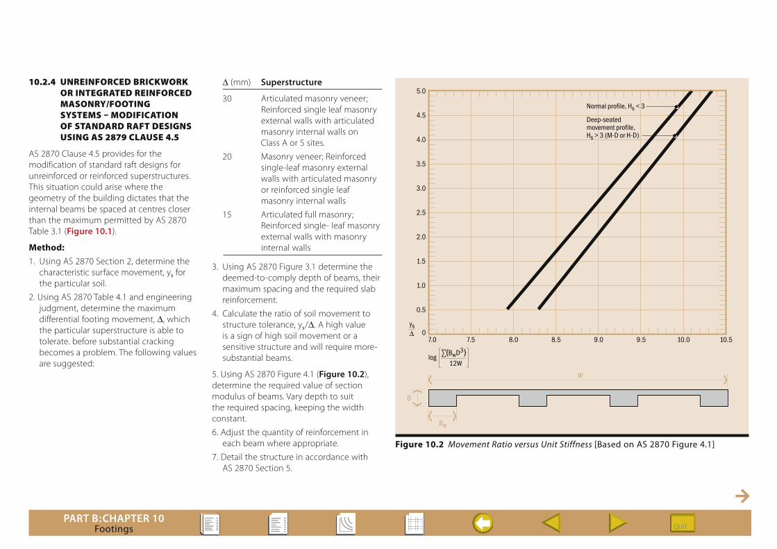
10.2.4 unReinfoRCed BRiCkwoRk oR inTegRATed ReinfoRCed mAsonRy/fooTing sysTems – modifiCATion of sTAndARd RAfT designs using As 2879 ClAuse 4.5
AS 2870 Clause 4.5 provides for the modification of standard raft designs for unreinforced or reinforced superstructures. This situation could arise where the geometry of the building dictates that the internal beams be spaced at centres closer than the maximum permitted by AS 2870 Table 3.1 (Figure 10.1).
Method:1. Using AS 2870 Section 2, determine the
characteristic surface movement, ys for the particular soil.
2. Using AS 2870 Table 4.1 and engineering judgment, determine the maximum differential footing movement, D, which the particular superstructure is able to tolerate. before substantial cracking becomes a problem. The following values are suggested:
D (mm) Superstructure
30 Articulated masonry veneer; Reinforced single leaf masonry external walls with articulated masonry internal walls on Class A or S sites.
20 Masonry veneer; Reinforced single-leaf masonry external walls with articulated masonry or reinforced single leaf masonry internal walls
15 Articulated full masonry; Reinforced single- leaf masonry external walls with masonry internal walls
3. Using AS 2870 Figure 3.1 determine the deemed-to-comply depth of beams, their maximum spacing and the required slab reinforcement.
4. Calculate the ratio of soil movement to structure tolerance, ys/D. A high value is a sign of high soil movement or a sensitive structure and will require more-substantial beams.
5. Using AS 2870 Figure 4.1 (Figure 10.2), determine the required value of section modulus of beams. Vary depth to suit the required spacing, keeping the width constant.
6. Adjust the quantity of reinforcement in each beam where appropriate.
7. Detail the structure in accordance with AS 2870 Section 5.
Normal profile, Hs < 3
7.0 7.5 8.0 8.5 9.0
W
D
Bw
9.5 10.0 10.50
0.5
1.0
1.5
2.0
2.5
3.0
3.5
4.0
4.5
5.0
Deep-seatedmovement profile,Hs > 3 (M-D or H-D)
ys∆
log ∑(BwD3)
12W
Figure 10.2 Movement Ratio versus Unit Stiffness [Based on AS 2870 Figure 4.1]

PART B:CHAPTER 10Footings
10.2.5 unReinfoRCed BRiCkwoRk – design of RAfT fooTing sysTems using As 2870 ClAuse 4.4
AS 2870 Clause 4.4 makes provision for the engineering design of raft slabs supporting unreinforced masonry superstructures. Methods of assessing the soil mound shape developed by both Walsh and Mitchell (Table 10.2) are given in AS 2870 Appendix F.
Method:1. Using AS 2870 Section 2, determine the
characteristic surface movement, ys for the particular soil.
2. Using AS 2870 Table 4.1 and engineering judgment, determine the maximum differential footing movement, D, which the particular superstructure is able to tolerate before substantial cracking becomes a problem. See suggested values in Clause 10.2.4.
3. Enter the structure geometry and capacities into a grillage program with spring supports (to simulate a compressible soil mound) and shortening or lengthening vertical supports (to simulate expanding or shrinking soil at the rim).
4. Perform a non-linear analysis to calculate the cantilever lengths and the corresponding moments, shears and deflections. These calculations should be done twice, once for a shrinking soil and once for an expanding soil.
5. Check the moment capacity and the stiffness of the slab and beams to cantilever or span without deflections exceeding the permissible.
6. Detail the structure in accordance with AS 2870 Section 5.
10.2.6 inTegRATed ReinfoRCed mAsonRy/fooTing sysTem – design using As 2870 ClAuse 4.7
If the designer wishes to achieve more economical designs for houses with reinforced superstructures than are given in the deemed-to-comply provisions of Figure 3.1 including Note 12, the following design approach can be taken.
Method:1. Using AS 2870 Section 2, determine the
characteristic surface movement, ys, for the particular soil.
2. Determine the required house geometry, wall layout, etc.
3. Determine the moment capacity, shear capacity, bending stiffness and shear stiffness of various combinations of: walls + slab + beams at continuous walls walls + slab (no beams) at continuous walls walls + slab + beams with openings walls + slab (no beams) with openings beams + slabs (no walls) slabs (no beams or walls).
4. Using Appendix F, (Table 10.2) determine the edge distance over which the soil shrinkage or expansion will occur.
5. Enter the structure geometry, capacities and edge distances into a grillage program with spring supports (to simulate a compressible soil mound). Shortening or lengthening vertical supports around the edge of the structure simulate shrinking or expanding soil at the rim. Alternatively, a simpler solution can be achieved by assuming that parts of the structure cantilever or span distances corresponding to the calculated edge distances.
6. Perform an analysis to calculate moments, shears and deflections. These calculations should be done twice, once for a shrinking soil and once for an expanding soil.
7. Check the shear and moment capacities of each wall/slab/beam combination to span without cracking, particularly at door and window openings.
8. Check the deflections at all openings and other strategic points to ensure that doors and windows can still open, plasterboard and cladding does not crack.
9. Detail the structure such that rotation and twisting of walls does not occur. For very long structures, it may be prudent to provide some articulation joints at suitable centres such that the ability to span is not impeded whilst the structure is not forced to span lengths in excess of those values dictated by the wall/footing strength.

PART B:CHAPTER 10Footings
Notations used by Mitchell in Table 10.2B = Width of footing area
E = Young’s Modulus of footing material
I = Moment of inertia of footing
L = Length of footing or covered area
M = Moment of superstructure loads about footing centre
Y = Maximum differential soil movement
k = Swelling stiffness
m = Power of polynomial defining soil surface under covered area, or shape factor
w = Superstructure loads per unit area of footing
D = Maximum differential footing movement
Moment Correction Factors (a+) for Sagging Condition with a Uniformly-distributed Load
mys/D w/kY 2.1 3 4 5 6 7 8 10 15 20
• >0.50 * * * * * * * * * * 0.30 0.46 0.67 0.89 * * * * * * * 0.20 0.35 0.33 0.33 0.57 0.89 * * * * * 0.10 0.23 0.20 0.19 0.18 0.17 0.17 0.17 0.33 0.83 * 0.05 0.16 0.14 0.12 0.11 0.11 0.10 0.10 0.09 0.09 0.18 0.01 0.07 0.06 0.05 0.05 0.04 0.04 0.04 0.03 0.03 0.03
2.50 >0.30 * * * * * * * * * * 0.20 0.56 0.99 * * * * * * * * 0.10 0.31 0.27 0.56 0.89 * * * * * * 0.05 0.20 0.17 0.15 0.13 0.20 0.48 0.70 0.98 * * 0.01 0.09 0.07 0.06 0.05 0.05 0.04 0.04 0.04 0.03 0.03
1.25 >0.10 * * * * * * * * * * 0.05 0.39 * * * * * * * * * 0.01 0.14 0.09 0.13 0.70 * * * * * *
Moment Correction Factors (a–) for Hogging Condition with a Uniformly-distributed Load
mys/D w/kY 2.1 3 4 5 6 7 8 9 10 15 20
• >1.00 * * * * * * * * * * * 0.50 0.69 0.72 0.76 0.79 0.81 0.83 0.84 0.86 0.87 0.90 0.93 0.10 0.41 0.48 0.55 0.60 0.64 0.68 0.71 0.73 0.75 0.82 0.86 0.01 0.19 0.27 0.35 0.41 0.46 0.51 0.54 0.58 0.61 0.71 0.77
2.50 >1.00 * * * * * * * * * * * 0.50 * * 0.87 0.90 0.92 0.94 0.96 0.97 0.98 * * 0.30 0.69 0.75 0.81 0.86 0.90 0.93 0.95 0.98 0.99 * * 0.10 0.49 0.61 0.73 0.82 0.91 0.97 * * * * * 0.01 0.24 0.45 0.85 * * * * * * * *
1.25 >0.30 * * * * * * * * * * * 0.20 * 0.92 * * * * * * * * * 0.10 0.70 0.98 * * * * * * * * * 0.01 0.37 * * * * * * * * * *
* Use minimum footings with check for bearing capacity considerations
Formulae used by Mitchell in Table 10.2
Moment and stiffness for sagging condition with a uniformly-distributed load:
M+ = wL2 B
(1 – a+)
EI = M+ L2
8 12D
Moment and stiffness for hogging condition with a uniformly-distributed load:
M− = wL2 B
(1 – a–)
EI = M– L2
8 12D
Table 10.2 Moment-Correction Coefficients (Extract from Mitchell)

PART B:CHAPTER 10Footings
10.2.7 deTAiling And ConsTRuCTion guidelines
This section provides explanations of AS 2870 Sections 5 and 6 for detailing and construction of the earthworks, slabs, footings and concrete masonry superstructure.
Clause 5.1 General
Clause 5.2 Drainage Clause 5.2.1 places requirements on floor levels, pointing out the need to consider plumbing, run-off, excavation, filling, flooding, landscaping, stormwater discharge and termite management.
Clause 5.2.2 permits the 150mm freeboard to be reduced in certain circumstances, such as sandy well drained soils (100 mm) and where external paved areas slope away (50 mm).
Clause 5.3 Requirements for rafts and slabsClause 5.3.1 requires concrete to be not less than Grade N20 with a 20 mm maximum aggregate size. The slump is not specified, but a maximum slump of 100 mm would be acceptable. Water must not be added on site
Clause 5.3.2 gives the requirements for reinforcement cover, laps, positioning and details.
Clause 5.3.3 gives the requirements for vapour barriers and damp-proofing membranes. Adjacent sheets are to be lapped, but there is no requirement for taping these laps except at plumbing penetrations. In South Australia and other areas prone to salt-damp, a high impact resistance barrier will be required.
Clause 5.3.4 provides specification for edge rebates, which should be detailed by the engineer.
Paragraph (d) of Clause 5.3.4, states that single-leaf masonry does not require an edge rebate. This is because this type of construction would incorporate reinforcement to minimise cracking and continuous weatherproofing paint system over the exposed surface of wall and beam.
Clause 5.3.5 provides specification for recesses.
Clause 5.3.6 provides specification for heating cables and pipes.
Clause 5.3.7 provides details for brittle floor coverings.
Clause 5.3.8 sets out the requirements for beam continuity in rafts. The exact locations of beams should be determined by the engineer with reference to Figure 5.4 and Table 3.1. Once this is done the structure should be examined to determine whether the size of the beams can be reduced using Clause 4.5.
Clause 5.3.9 requires the first internal beam to be within 4.0 metres of the external beam for Class M and H sites, thus ensuring additional stiffness at the location where the beam/slab system could be suspended when the soil shrinks.
Clause 5.4 Requirements for pad and strip footingsClauses 5.4.1 and 5.4.2 set out the requirements for concrete and reinforcement similar to the case for slabs.
Clause 5.4.3 limits the slope of footings to1 in 10 and provides details of how steps may be achieved.
Clause 5.5 Requirements in Agressive Soils
Clause 5.5.1 General
Clause 5.5.2 Isolation from the ground
Clause 5.5.3 Concrete strength and detailingl
Clause 5.6 Additional requirements for Class M, H1, H2 and E Sites
Clause 5.6.1 requires architectural solutions to reduce the effects of movement in Class H or E sites, including detailing masonry, isolation and articulation.
Clause 5.6.2 requires continuity of slabs over rock.
Clause 5.6.3 requires enhanced drainage.
Clause 5.6.4 requires enhanced plumbing.
Clause 6.1 GeneralSee also Clause 6.4.7 for placing and compacting concrete.
Clause 6.2 Permanent excavationsClause 6.2 restricts excavations over 600 mm deep.
Clause 6.3 Temporary excavationsClause 6.3 restricts the location of service trenches.
Clause 6.4 Construction of slabsClause 6.4.1 notes that land slip may need to be considered separately.
Clause 6.4.2 provides rules for filling.
Clause 6.4.3 and Commentary C6.4.3 provides guidance on:
Stripping Top Soil
Avoiding Erosion. On sloping sites liable to erosion by surface water, edge beams are to be protected by: – Grading the ground surface to limit the catchment area adjacent to the building to less than 100 square metres; or
– Providing a drainage system which prevents run-off near the building; or
– Providing a 600 mm-wide concrete path around the building; or
– Founding the edge beam at least 300 mm below the finished ground level.

PART B:CHAPTER 10Footings
Allowable Bearing Pressures
Slope of Beams. A maximum slope of 1 in 10 is permitted. This would be determined by the designer.
Blinding Layer. It is not a requirement to place a sand layer under the slab, although it may be desirable in order to reduce concrete use and avoid rupturing the membrane.
Clause 6.4.4 gives three alternatives for sloping sites.
Clause 6.4.5 gives the methods of retaining fill for Class A, S or M sites.
Clause 6.4.6 states the need for fixing reinforcement.
Clause 6.4.7 states that concrete shall be placed and compacted in accordance with good building practice. Commentary C6.1 further expands this and explains that vibration is a requirement only on Class H1, H2 and E sites.
However, it is of the opinion of the Concrete Masonry Association of Australia that both vibration and curing are beneficial and have therefore been included in the Specification in this manual.
Clause 6.5 Construction of strip and pad footings
Clause 6.5 provides details of strip and pad footings. Alternatively, for a Class A or S site, strip or pad footings may be founded on controlled sand fill.
Clause 6.6 Additional requirements for Moderately, Highly, and Extremely Reactive Sites
The following additional requirements are detailed for Class H and E sites.
(a) Detailing.
(b) Sleeving of penetrations to avoid rupture due to differential movement.
(c) Collection and channelling of run-off.
(d) Avoidance of back-filling with porous material.
(e) Avoidance of water ponding in trenches.
(f ) Articulation of pipe joints within 3 metres of the building.
(g) Vibration of concrete and fixing of reinforcement.
PART B:CHAPTER 10Footings
10.3.1 geneRAl
Design and detailingAll design and detailing shall comply with the requirements of AS 2870 for concrete slabs and footings, and AS 3700 for concrete masonry.
It is the designer’s responsibility to allow for the effects of control joints, chases, openings, strength and stiffness of ties and connectors, and strength and stiffness of supports, in addition to normal considerations of loads and masonry properties. Control joints and openings must be treated as free ends as specified by AS 3700.
Masonry propertiesThe standard designs in this chapter are based on masonry properties complying with the General Specification set out in Part C:Chapter 2, modified as noted on the standard design chart and as noted below.
Hollow concrete blocksWidth 90 mm, 110 mm, 140 mm and 190 mm
Height 190 mm
Length 390 mm
Face-shell bedded
Minimum face-shell thickness, ts = 25 mm for 90 mm, 110 mm and 140 mm units ts = 30 mm for 190 mm units
Minimum characteristic compressive strength, f ’uc =15 MPa
Minimum characteristic lateral modulus of rupture, f ’ut = 0.8 MPa
Solid or cored concrete bricksWidth 110 mm
Height 76 mm
Length 230 mm
Fully bedded
Minimum characteristic compressive strength, f ’uc =10 MPa
Minimum characteristic lateral modulus of rupture, f ’ut = 0.8 MPa
Mortar jointsMortar type M3 (or M4)
Joint thickness 10 mm
Concrete groutMinimum characteristic compressive strength, f ’c = 20 MPa
Minimum cement content 300 kg/m3
Steel reinforcementN12, or N16 as noted. Fabric and trench mesh as noted.
Concrete slabs-on-ground and footingsStrength grade N20
Maximum slump 100 mm
Maximum aggregate size 20 mm
10.3.2 index To design ChARTs
Design charts contain data for Design By Engineering Principles. The data may be used in manual or computer analyses used to design by engineering principles in accordance with AS 2870 Section 4.
Chart Index
Typical Edge Distances for Slabs on Reactive Soils
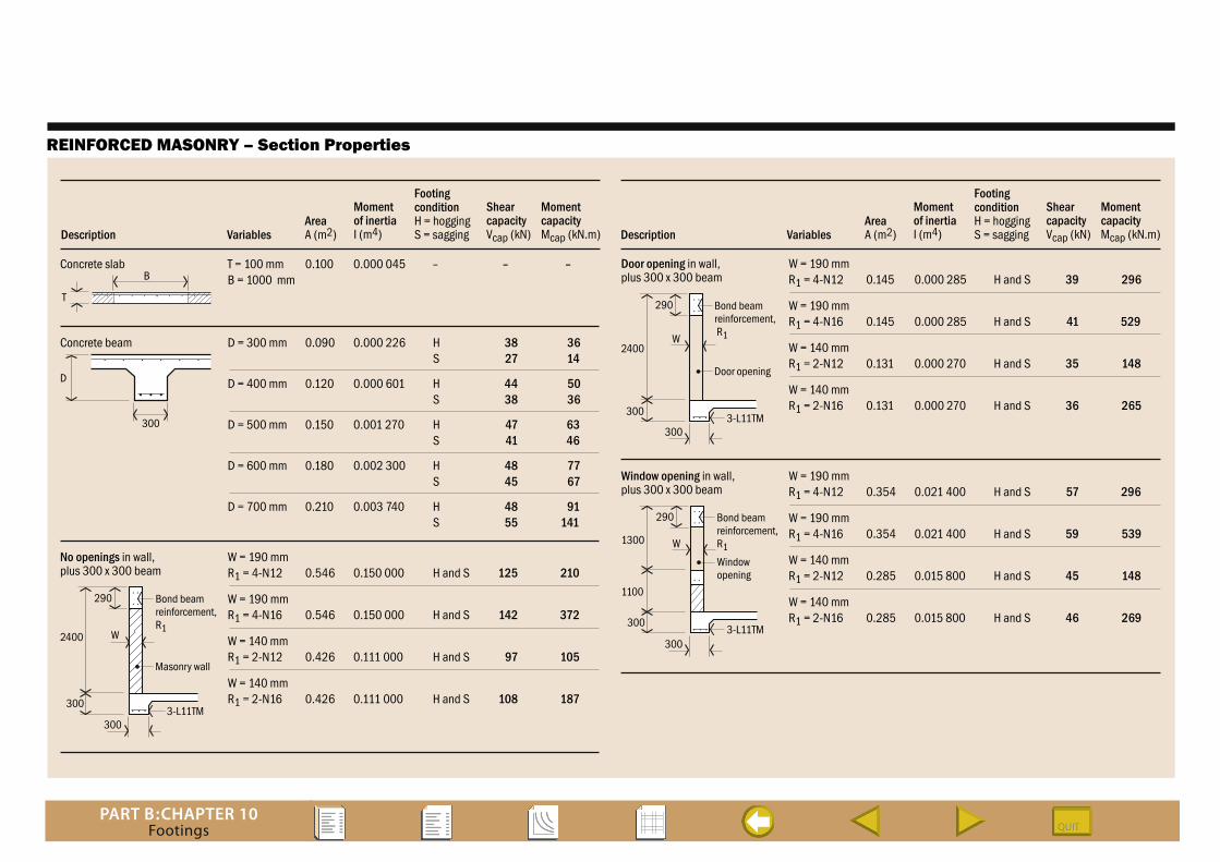
Reinforced Masonry – Section Properties
10.3 sTAndARd designs

PART B:CHAPTER 10Footings
TYPICAL EDGE DISTANCES FOR SLABS ON REACTIVE SOILS
* Limit values apply ( 0.6 +
ym ) 0.025
S
Surfacemovementys (mm)
Moundmovementym (mm)
Depth ofsuctionHs (m)
Minimumedge distancee (m)Site Class
EDGE DISTANCE FOR CENTRE-HEAVE
0 0 1.2 0.15 1.5 0.19
10 7 1.2 0.34 1.5 0.38
20 14 1.2 0.54 1.5 0.58
0 0 6.0 0.60* 7.5 0.60* 9.0 0.60*
10 7 6.0 0.88* 7.5 0.88* 9.0 0.88*
20 14 6.0 1.16* 7.5 1.16* 9.0 1.16*
Surfacemovementys (mm)
Moundmovementym (mm)
SlablengthL (m)
Minimumedge distancee (m)
EDGE DISTANCE FOR EDGE-HEAVE
H 50 35 1.8 1.20 2.1 1.23
60 42 1.8 1.39 2.1 1.43
70 49 1.8 1.59 2.1 1.62
50 35 6.0 1.20 7.5 1.50 9.0 1.80
60 42 6.0 1.20 7.5 1.50 9.0 1.80
70 49 6.0 1.20 7.5 1.50 9.0 1.80
M 30 21 1.5 0.77 1.8 0.81
40 28 1.5 0.97 1.8 1.00
30 21 6.0 1.20 7.5 1.44* 9.0 1.44*
40 28 6.0 1.20 7.5 1.50 9.0 1.72*
Calculated in accordance with AS 2870 Clauses F4 (a), (b) and (c)
Differential mound movement (mm), ym = 0.7 ys
Allowable bearing pressure: Centre-heave (shrinking soil) – 5000 kPa/m (except at edges where a very low value is used) Edge-heave (swelling soil) – 1000 kPa/m under edge beams (Zero assumed elsewhere)
Edge distance from centre-heave (m), e = Hs
+ ym
8 0.036
Edge distance from edge-heave (m), e = 0.2 L ≤ 0.6 +
ym 0.025
BASIS OF TABLES
PART B:CHAPTER 10Footings
REINFORCED MASONRY – Section Properties
Concrete slab
AreaA (m2)
Momentof inertiaI (m4)
ShearcapacityVcap (kN)
MomentcapacityMcap (kN.m)
FootingconditionH = hoggingS = saggingDescription Variables
T = 100 mm 0.100 0.000 045 – – – B = 1000 mm
Concrete beam D = 300 mm 0.090 0.000 226 H 38 36 S 27 14
AreaA (m2)
Momentof inertiaI (m4)
ShearcapacityVcap (kN)
MomentcapacityMcap (kN.m)
FootingconditionH = hoggingS = saggingDescription Variables
No openings in wall,plus 300 x 300 beam
W = 190 mmR1 = 4-N12 0.546 0.150 000 H and S 125 210
W = 190 mmR1 = 4-N16 0.546 0.150 000 H and S 142 372
W = 140 mmR1 = 2-N12 0.426 0.111 000 H and S 97 105
W = 140 mmR1 = 2-N16 0.426 0.111 000 H and S 108 187
D = 400 mm 0.120 0.000 601 H 44 50 S 38 36
D = 500 mm 0.150 0.001 270 H 47 63 S 41 46
D = 600 mm 0.180 0.002 300 H 48 77 S 45 67
D = 700 mm 0.210 0.003 740 H 48 91 S 55 141
Door opening in wall,plus 300 x 300 beam
W = 190 mmR1 = 4-N12 0.145 0.000 285 H and S 39 296
W = 190 mmR1 = 4-N16 0.145 0.000 285 H and S 41 529
W = 140 mmR1 = 2-N12 0.131 0.000 270 H and S 35 148
W = 140 mmR1 = 2-N16 0.131 0.000 270 H and S 36 265
T
B
D
300
2400
Masonry wall
300
300
290
W
Bond beamreinforcement,R1
3-L11TM
3-L11TM
3-L11TM
Window opening in wall,plus 300 x 300 beam
W = 190 mmR1 = 4-N12 0.354 0.021 400 H and S 57 296
W = 190 mmR1 = 4-N16 0.354 0.021 400 H and S 59 539
W = 140 mmR1 = 2-N12 0.285 0.015 800 H and S 45 148
W = 140 mmR1 = 2-N16 0.285 0.015 800 H and S 46 269
300
300
2400
Door opening
300
290
W
Bond beamreinforcement, R1
1300
1100
300
Windowopening
290
W
Bond beamreinforcement,R1

PART B:CHAPTER 10Footings
10.4 woRked exAmPle
Purpose of the worked exampleThe purpose of the following worked example is to demonstrate the steps to be followed when performing manual calculations or when preparing computer software for the analysis and design of masonry. The worked example also serves the purpose of demonstrating the origin of the Standard Designs which are based on similar masonry capacity considerations. Although comprehensive in its treatment of AS 2870, the worked example is not intended to analyze or design all parts of the particular structure. It deals only with enough to demonstrate the design method.
Design and detailingAll design and detailing shall comply with the requirements of AS 2870 and, where appropriate, AS 3700.
It is the designer’s responsibility to allow for the effects of control joints, chases, openings, strength and stiffness of ties and connectors, and strength and stiffness of supports, in addition to normal considerations of loads and masonry properties. Control joints and openings must be treated as free ends as specified by AS 3700.
Masonry propertiesThe worked examples in this chapter are based on masonry properties complying with the General Specification set out in Part C:Chapter 2, modified as noted in the calculations and as noted below.
Hollow concrete blocksWidth 90 mm, 110 mm, 140 mm and 190 mm
Height 190 mm
Length 390 mm
Face-shell bedded
Minimum face-shell thickness, ts = 25 mm for 90 mm, 110 mm and 140 mm units ts = 30 mm for 190 mm units
Minimum characteristic compressive strength, f ’uc =15 MPa
Minimum characteristic lateral modulus of rupture, f ’ut = 0.8 MPa
Solid or cored concrete bricksWidth 110 mm
Height 76 mm
Length 230 mm
Fully bedded
Minimum characteristic compressive strength, f ’uc =10 MPa
Minimum characteristic lateral modulus of rupture, f ’ut = 0.8 MPa
Mortar jointsMortar type M3 (or M4)
Joint thickness 10 mm
Concrete groutMinimum characteristic compressive strength, f ’c = 20 MPa
Minimum cement content 300 kg/m3
Steel reinforcementN12, or N16 as noted. Fabric and trench mesh as noted.
Concrete slabs-on-ground and footingsStrength grade N20
Maximum slump 100 mm
Maximum aggregate size 20 mm
Index to parts of worked example
Worked example involves design of the slab and beams for a house, with alternative types of superstructures, using different methods as follows:
1 Unreinforced masonry superstructure using deemed-to-comply provisions of AS 2870 Figure 3.1.
2 Reinforced masonry superstructure using deemed-to-comply provisions of AS 2870 Figure 3.1 and Clause 3.2.5.
3 Reinforced or unreinforced superstructure by modifying standard designs using AS 2870 Clause 4.5.
4 Unreinforced masonry superstructure using AS 2870 Clause 4.4.
5 Reinforced masonry superstructure using AS 2870 Clause 4.7.
GO TO WORKED EXAMPLE

PART B:CHAPTER 10Footings
Worked Example [Page 1 of 10]
For the house plan shown below, design the slabs and beamsfor alternative types of superstructures, using the following:
1 Design for unreinforced masonry superstructure using deemed-to-comply provisions of AS 2870
Figure 3.1
2 Design for reinforced masonry superstructure using deemed-to-comply provisions of AS 2870 Figure 3.1
and Note 12
3 Design for reinforced or unreinforced superstructure by modifying standard designs using AS 2870 Clause 4.5
4 Design for unreinforced masonry superstructure using AS 2870 Clause 4.4
5 Design for reinforced masonry superstructure using AS 2870 Clause 4.7
DESIGN BRIEF
Note:Only reinforced masonry internal walls shown
Bed 1Bed 2 Lounge Garage
Bed 3 WC Bath Family
13 000
Kitchen
Dining
7000
W'shop
HOUSE PLAN
Internal slabs without walls P = 1.0 PL slab + 0.5 IL = (1.0 x 25 x 0.1 x 1.3) + (0.5 x 1.5) = 4.0 kN/m2
External walls P = 1.0 PL slab + wall + footing + roof + 0.5 IL = 1.0[(25 x 0.1 x 0.5) + (2.5 x 1.72) + (0.3 x 0.3 x 25) + (1.0 x 8.0)] + 2
(0.5 x 1.5 x 0.5)
= 12.2 kN/m
Average bearing pressure
qua = 1500
13.0 x 7.0 = 16.5 kPa
Bearing pressure under external walls
que = 12.2
1.0 x 0.3 = 40.7 kPa
Bearing pressure under internal walls
Minimum permissible bearingstrength at working loads, underslabs and beams, is 50 kPa OK
qui = 8.0
1.0 x 0.3 = 27.7 kPa
BEARING CALCULATIONS
Internal walls P = 1.0 PL slab + wall + footing + 0.5 IL = 1.0[(25 x 0.1 x 0.7) + (2.5 x 1.39) + (0.3 x 0.3 x 25)] + (0.5 x 1.5 x 0.7) = 8.0 kN/m
Total factored loads Pt = (40 x 12.2) + (33 x 8.0) + (187 x 4.0) = 1500 kN
6.4.3
NOTE:References are to AS 2870, unless stated otherwise

PART B:CHAPTER 10Footings
Worked Example [Page 2 of 10]
Visual Assessment of SiteWhat are the site dimensions and layout? How much does the site slope?Are there existing buildings on site? Are existing buildings cracked?Are there buildings adjacent to the site? Are adjacent buildings cracked?Are there existing trees? Is it intended to remove any trees?Is it intended to plant any trees? Will removal or planting of trees affect moisture content?Is there any existing fill? Is it intended to bench the site with cut and fill?
Required Number of Test Bore HolesIs deep-seated foundation movement expected? ie Hs > 3.0
Yes Use three bore holes per site Clause 2.2.3(b) No Is the site part of a subdivision with uniform soil strata which can be determined from soil maps?
Yes Use reduced number of bore holes per site. Number of holes required? Clause 2.2.3(b) No Use one bore hole per site Clause 2.2.3(a)
Required Depth of Test Bore HolesIs depth of design suction change, Hs > 2.0 m?(In Sydney, Gosford, Newcastle and Hunter Valley, Hs = 1.5 m Table 2.4)
Yes Use hole depth, d = 0.75 Hs No Has rock been encountered?
Yes Use hole depth, d = depth to rock No Is the classifier's opinion that further drilling is unnecessary to identify the profile? Yes Use hole depth, d = depth specified by classifier No Use hole depth, d = 1.5 m
Determination of Soil Shrinkage Index, IpsAre laboratory tests to AS 1289.7.1.1,2 and 3 available?
Yes Use Ips from tests Clause 2.2.3(a) No Are correlations between shrinkage index, Ips, and other clay index tests available?
Yes Use Ips from the correlations Clause 2.2.3(b) No Use visual tactile identification by an engineer or engineering geologist having appropriate expertise and local experience to estimate soil shrinkage index, I ps
Clause 2.2.3(c)
Determination of Characteristic Surface Movement, ysDepth of crack zone: 0.33Hs to Hs Table 2.4
In Adelaide and Melbourne = 0.75Hs or to water table In Sydney, Gosford, Newcastle and Hunter Valley = 0.5Hs or to water table = 0.5 x 1.5 m = 0.75 m
In the cracked zone, alpha = 1.0In the uncracked zone, alpha = 2.0 - z/5000 (Where z is in mm)Instability Index, Ipt = alpha x IpsChange in suction at soil surface, du = pF (For Sydney, du = 1.5pF)
Determination of Site Class
0 mm < ys < = 20 mm S 20 mm < ys < = 40 mm M 40 mm < ys < = 70 mm H ys < = 70 mm E
Hole Number 1: Soil Type Depth, z Interval, Alpha Soil shrinkage Instability Suction, Ipt du dz mm dz index, Ips index, Ipt du pF
Characteristic Surface Movement, ys
Table 2.3
SITE CLASSIFICATIONUsing Site Classification Form
No300 mmNA
No
NoNo No
Cut onlyNo
YesYes
See dwg
Light claywith sand
Heavybrown clay
Ssoil
andy
0-800 800
300
400
1.0
1.8
–
0.020
0.016
–
0.020
0.029
–
1.5
1.5
–
24
13
–
800-1100
1100-1500
37

PART B:CHAPTER 10Footings
Worked Example [Page 3 of 10]
NOTE:
References are to AS 2870, unless stated otherwise
Site Classification: M
Walls: Articulated masonry veneer
From AS 2870 Figure 3.1…
Edge and internal beam depth
D = 400 mm
Bottom reinforcement
3-L11TM
Maximum beam spacing
6.0 m
Slab fabric
SL72
1 DESIGN FOR UNREINFORCED MASONRYSUPERSTRUCTURE USING DEEM-TO-COMPLYPROVISIONS OF AS 2870 FIGURE 3.1
3-L11TM 3-L11TM
SL72SL72
400
300 300
100
Internal beams
Depth, Di = 400 mm
Reinforcement, 3-L11TM
Maximum spacing, 5.0 m
Slabs
Depth, Ds = 100 mm
Reinforcement, SL72
External beams
Using AS 3700 Clause 3.2.5, external beams
may be reduced to 300 x 300 with 3-11TM
reinforcement.
Provide continuity at re-entrant corners and beams.
Lap internal beam reinforcement into external
Site Classification: M
External walls: Reinforced single-leaf masonry
Internal walls: Reinforced single-leaf masonry
Equivalent construction: Masonry veneer
Table 3.1
From AS 2870 Figure 3.1…
3-L11TM 3-L11TM
SL72SL72300
300 300
400
Reinforced 190-mm concretemasonry superstructure
N 12 bars @ 2000 crsN20 grout
2 DESIGN FOR REINFORCED MASONRYSUPERSTRUCTURE USING DEEM-TO-COMPLYPROVISIONS OF AS 2870 FIGURE 3.1 NOTE 12

PART B:CHAPTER 10Footings
Worked Example [Page 4 of 10]
Check Design Parameters
Using Figure 4.1
3 DESIGN FOR REINFORCED OR UNREINFORCEDMASONRY SUPERSTRUCTURE BY MODIFYINGSTANDARD DESIGNS USING AS 2870 CLAUSE 4.5
Table 4.1
log (Bw D3) = 8.59
12 W
This value can be calculated for Hs < 3 using thefollowing formula, then checked visually fromFigure 4.1
Longitudinal Beams
8.59 = log 300 Dl
3 x 3
12 x 7.0
Width of beam
Bw = 300 mm
Dl = 329 mm
Width of slab
W = 7.0 m
Number of beams
n = 3
Depth of beam
Transverse Beams
8.59 = log 300 Dl
3 x 5
12 x 13.0
Width of beam
Bw = 300 mm
Dl = 341 mm
Width of slab
W = 13.0 m
Number of beams
n = 5
Depth of beam
NOTE:
References are to AS 2870, unless stated otherwise

PART B:CHAPTER 10Footings
Worked Example [Page 5 of 10]
4 DESIGN FOR UNREINFORCED MASONRY SUPERSTRUCTURE USING AS 2870 CLAUSE 4.4
NOTE:References are to AS 2870, unless stated otherwise
Soil Movement/Structure Sensitivity
Table 4.1
Length of transverse beams L = 7000 mm
Bearing Pressure RatioSwell stiffness k = 1000 kPa/m
Footing ExposureDepth of design suction change Hs = 1500 mm
Depth of footing below ground D = 300 mm
Ground around the house is impermeable g = 0.75 a = Hs - D = 1500 - 300 = 1200 mm
Average factored bearing pressure w = 16.5 kPa
Bearing pressure ratio
Equivalent construction Masonry veneer
Permissible deflection
< 20 OK
w = 16.5
k ys 1000 x 0.037 = 0.45
Moments and Required Stiffness Using Mitchell's tablesFor sagging, use the minimum footing specifiedin AS 2870 ie 300 mm x 380 mm deep with 3-L11TM and SL72 fabri c
Shape factor
m = g L
a
= 0.75 x 7000 1200 = 4.4

PART B:CHAPTER 10Footings
Worked Example [Page 6 of 10]
NOTE:
References are to AS 2870, unless stated otherwise
Beam Moment and Shear CapacitiesConcrete cover
CT = 20 mm (To top of slab)
CB = 30 mm (To membrane)
Beam effective width
beff = 2.0 maximum for edge beams
or 4.0 maximum for internal beams
or half way to adjacent beams
For hogging of an edge beam
C = 20 mm
beff =
3.5 2
= 1750 mm
Effective depth
d = D - C - Transverse bars -
dia 2
= 380 - 20 - 7 - 7
2
= 349 mm
4.4(e) also AS 3600 8.5.3.1
Effective moment of inertia
I = 0.045 beff d
3 (0.7 + 0.3 bw )3
beff
= 0.045 x 1750 x 3493 (0.7 + 0.3 300 )3
1750
= 1.42 x 109 mm4
= 0.00142 m4
> 10,096 kN.m2 OK
Elastic modulus of concrete
Ec = 15 000 MPa
= 15 x 106 kN/m2
Tensile strength of concrete
ft = 1.8 MPa for hogging
Cracking moment
Mcr = ft Zeff
= 1.8 x 103 x 0.00814
= 14.6 kNm
Stiffness parameter
EI = 15 x 106 x 0.00142
= 21,300 kN.m2
4.4(i)
Zeff =
Ieff
0.5d
= 0.00142
0.5 x 349
= 0.00814 m3
FOR BENDING MOMENT:
Capacity reduction factor
ø = 0.6
Yield strength of steel
fy = 500 MPa
> 1.2 Mcr= 1.2 x 14.6
= 17.5 kNm OK
> 28.9 kNm OK
Characteristic strength of concrete
f'c = 20 MPa
AS 3600 Table 2.2.2
Area of tensile steel (8 bars)
As =
8 x 3.1416 x 72
4
= 308 mm2
Moment capacity
Mcap = 0.6fy As d
(1 - 0.6 fy As )
f'c b d
= 0.6 x 500 x 308 x 349 x
106
(1 - 0.6 x 500 x 308 ) 1 x 20 x 300 x 349
= 30.8 kNm

PART B:CHAPTER 10Footings
Worked Example [Page 7 of 10]
FOR SHEAR:
Capacity reduction factor
ø = 0.7 AS 3600 Table 2.2.2
AS 3600 8.2.7.1
Vus = 0
Vcap = ø Vu
= ø (Vuc + Vus)
= 0.7 (56.3 + 0)
= 39.4 kN
AS 3600 8.2.2
Shear capacity
Vo = 0
Pv = 0
> 16.5 kN OK
5 DESIGN FOR REINFORCED MASONRYSUPERSTRUCTURE USING AS 2870 CLAUSE 4.7
4.4(f)
Ib = 0.045 b d3
= 0.045 x 190 x 1903 1012
= 0.0000586 m4
= 58.6 x 10⁻⁶ m4
As = 2 x 110
= 220 mm2
Area of tensile steel
d = 190 mm
Effective depth
b = 190 mm
Width
E = 15 000 MPa
= 15 x 106 kN/m2
Elastic modulus
Effective moment of inertia
EI = 15 x 106 x 58.6 x 10-6
= 879 kNm2
Stiffness parameter
Section Properties at Door Openings
(i) Bond beam190
190290
100
4-N12 bars
NOTE:
References are to AS 2870, unless stated otherwise
> 0.8

PART B:CHAPTER 10Footings
Worked Example [Page 8 of 10]
NOTE:
References are to AS 2870, unless stated otherwise
As = 285 mm2
Area of tensile steel
b = 300 mm
Width
dbot = 300 - 30 - 8
- 10 2
= 256 mm
Effective depths
(ii) Footing
300
300
100
dtop = 300 - 20 - 7 - 7
2
= 269 mm
4.4(f)
Ib = 0.045 b d3
= 0.045 x 300 x 2563 1012
= 0.000226 m4
= 226 x 10-6 m4
EIcom = 879 + 3396
= 4275 kNm2
NOTE: If the opening coincides with the point of
support for a cantilevering wall, some modification
of the stiffness may be required. See Report by
Symons, MG – Strength of Masonry Wall Panels
NOTE: This is a little more conservative
than using AS 3600
NOTE: Combined reinforcement in slab
and footing will exceed beam steel
E = 15 000 MPa
= 15 x 106 kN/m2
Elastic modulus
Effective moment of inertia
(iii) Combined stiffness
Capacity reduction factor
ø = 0.75
(iv) For bending
Steel strength
fsy = 500 MPa for bars in beam (and mesh)
Area of tensile steel
As = 4 x 110
= 440 mm2
EI = 15 x 106 x 226 x 10-6
= 3396 kNm2
Stiffness parameter
AS 3700 Table 4.1
h = 2400 - 290
+ 300
2 2
= 2405 mm
Lever arm
2400
300 Mu ø fs Ast h
= 0.75 x 500 x 440 x 2405 106
= 396 kNm
Moment capacity
290
AS 3600 Table 2.2.2Capacity reduction factor
ø = 0.7
Effective depth
do = 256 mm
(v) For shear
FOOTING:
AS 3600 Table 8.2.7.1
> 0.8

PART B:CHAPTER 10Footings
Worked Example [Page 9 of 10]
Vo = 0
Pv = 0
Vus = 0
Vcap = ø Vu
= ø (Vuc + Vus)
= 0.7 (39 + 0)
= 27.3 kN
AS 3600 8.2.2
Shear capacity of footing
AS 3700 Table 4.1
AS 3700 3.3.4
Capacity reduction factor
ø = 0.75
Characteristic shear strength
f'ms = 0.35 MPa
BOND BEAM:
Vcom = 27.3 + 12.4
= 39.7 kN
COMBINED SHEAR STRENGTH:
Vd = ø (f'ms bv d + fvs Ast + fsy Asv
d ) S
= 0.75 (0.35 x 190 x 190) + (17.5 x 220)
1000
= 12.4 kN
Shear capacity of bond beam
NOTE: Calculations of I, M and V at wall without
openings, wall with windows and wall without
footings would all be similar
Characteristic surface movement
ys = 37 mm
Differential mound movement
ym = 0.7 ys
e = Hs +
ym 8 36
= 1.5
+ 26
8 36
= 0.91 m
Edge distance for centre heave
Site Classification: M
Computer Runs
F4(a)
(ym in mm)
e = 0.2 L (0.6 + ym )
25
= (0.2 x 13.0) 0.6 + 26
25
= 1.4 1.64
Edge distance for edge heave
Four computer runs using Microstran V 5.5
have been done
Slabs and beams complying with AS 2870
Figure 3.1
External beams: 300 x 400
Internal beams: 300 x 400
Maximum deflection: 15.5 mm
Differential deflection: 15.3 mm
or (0.2 x 7.0)
Run 1
NOTE:
References are to AS 2870, unless stated otherwise

PART B:CHAPTER 10Footings
Worked Example [Page 10 of 10]
NOTE:References are to AS 2870, unless stated otherwise
Slabs and beams complying with AS 2870Figure 3.1 and Note 12Reinforced masonry external wallsExternal beams: 300 x 300Internal beams: 300 x 400
Maximum deflection: 3.3 mmDifferential deflection: 0.8 mm
Run 2
Same as Run 2, but with reinforced masonryinternal walls
Maximum deflection: 3.2 mmDifferential deflection: 0.6 mm
Run 3
Computer run samples
Same as Run 3, but without any internal beams
Maximum deflection: 3.4 mmDifferential deflection: 1.1 mm
Run 4
Permissible deflection for masonry veneer(which is the equivalent of reinforced externaland internal walls) Table 3.1
All the cases with reinforced masonry superstructuresexhibit deflections considerably less than this limit!
Hence, considerable structural advantage.
Table 4.1