Embed Size (px)
Citation preview
Part 2: optical and fiber physics
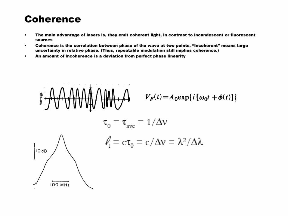
Coherence
• The main advantage of lasers is, they emit coherent light, in contrast to incandescent or fluorescent
sources
• Coherence is the correlation between phase of the wave at two points. “Incoherent” means large
uncertainty in relative phase. (Thus, repeatable modulation still implies coherence.)
• An amount of incoherence is a deviation from perfect phase linearity

Coherence and interferometers
– Temporal coherence: unequal-arm Michelson or Mach-Zehnder interferometer
interferes wave at one time with same wave at later time
• Detect interference term with photodiode, measures correlation
• See fringes vanish as time separation is increased
Fringe visibility
laser
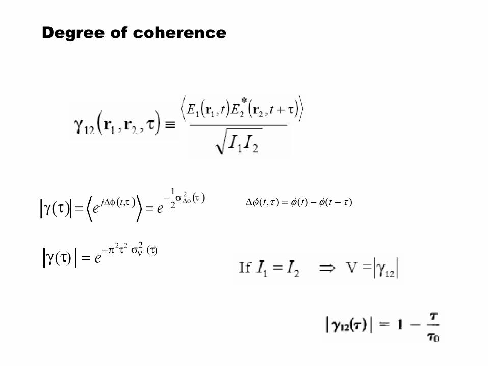
Degree of coherence
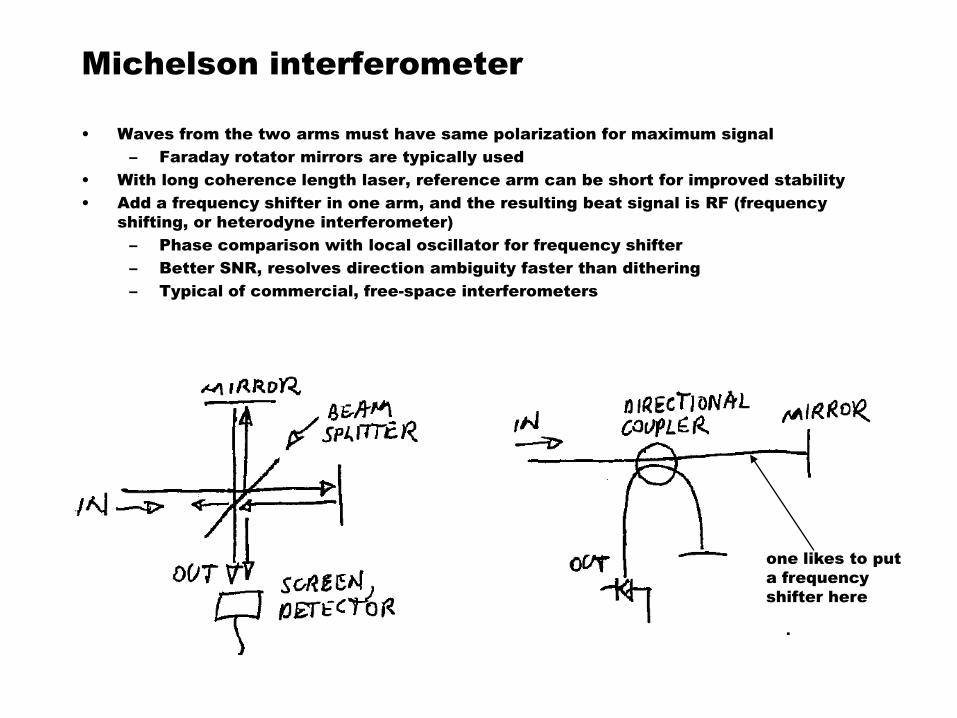
Michelson interferometer
• Waves from the two arms must have same polarization for maximum signal
– Faraday rotator mirrors are typically used
• With long coherence length laser, reference arm can be short for improved stability
• Add a frequency shifter in one arm, and the resulting beat signal is RF (frequency
shifting, or heterodyne interferometer)
– Phase comparison with local oscillator for frequency shifter
– Better SNR, resolves direction ambiguity faster than dithering
– Typical of commercial, free-space interferometers
one likes to put
a frequency
shifter here
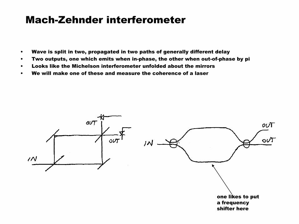
Mach-Zehnder interferometer
• Wave is split in two, propagated in two paths of generally different delay
• Two outputs, one which emits when in-phase, the other when out-of-phase by pi
• Looks like the Michelson interferometer unfolded about the mirrors
• We will make one of these and measure the coherence of a laser
one likes to put
a frequency
shifter here
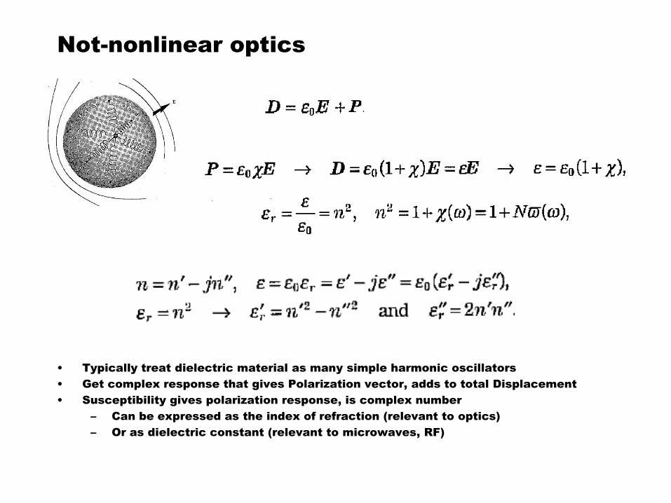
Not-nonlinear optics
• Typically treat dielectric material as many simple harmonic oscillators
• Get complex response that gives Polarization vector, adds to total Displacement
• Susceptibility gives polarization response, is complex number
– Can be expressed as the index of refraction (relevant to optics)
– Or as dielectric constant (relevant to microwaves, RF)
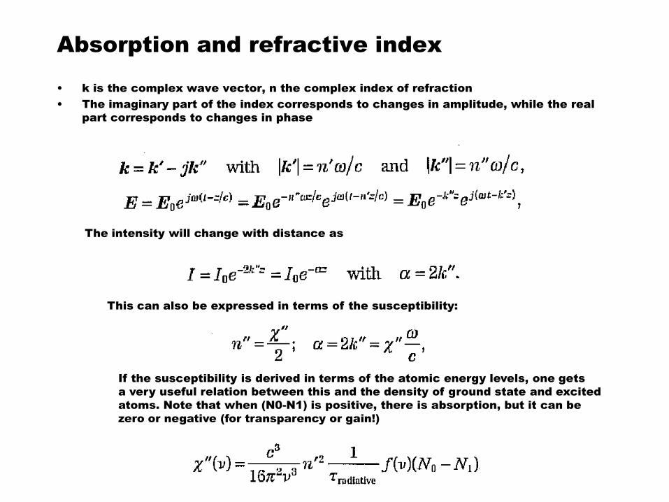
Absorption and refractive index
• k is the complex wave vector, n the complex index of refraction
• The imaginary part of the index corresponds to changes in amplitude, while the real
part corresponds to changes in phase
The intensity will change with distance as
This can also be expressed in terms of the susceptibility:
If the susceptibility is derived in terms of the atomic energy levels, one gets
a very useful relation between this and the density of ground state and excited
atoms. Note that when (N0-N1) is positive, there is absorption, but it can be
zero or negative (for transparency or gain!)
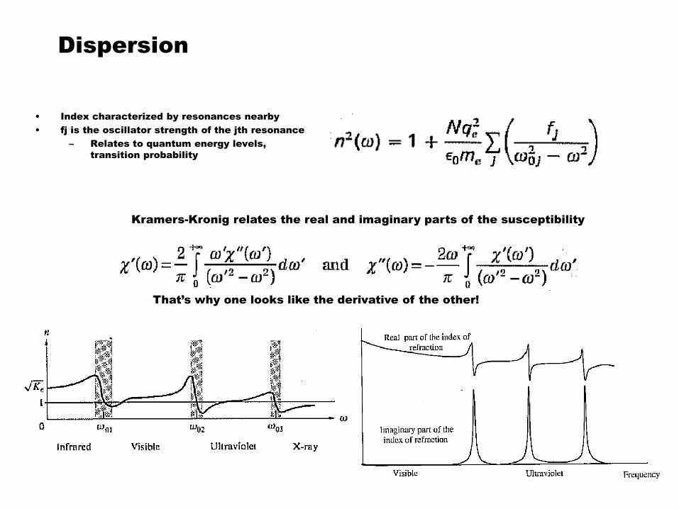
Dispersion
• Index characterized by resonances nearby
• fj is the oscillator strength of the jth resonance
– Relates to quantum energy levels,
transition probability
Kramers-Kronig relates the real and imaginary parts of the susceptibility
That’s why one looks like the derivative of the other!
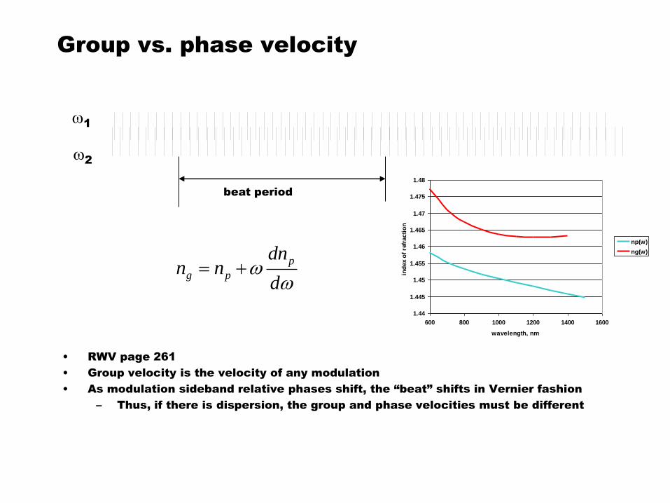
Group vs. phase velocity
• RWV page 261
• Group velocity is the velocity of any modulation
• As modulation sideband relative phases shift, the “beat” shifts in Vernier fashion
– Thus, if there is dispersion, the group and phase velocities must be different
w1
w2
beat period
ww
d
dnnn
p
pg
1.44
1.445
1.45
1.455
1.46
1.465
1.47
1.475
1.48
600 800 1000 1200 1400 1600
wavelength, nm
ind
ex
of
refr
acti
on
np(w)
ng(w)
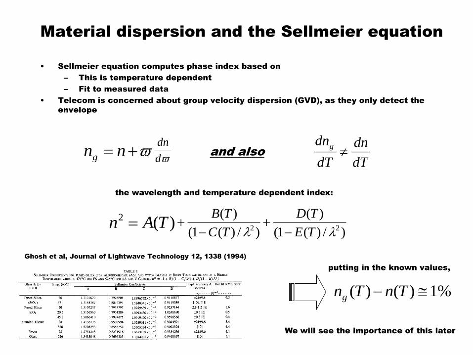
Material dispersion and the Sellmeier equation
• Sellmeier equation computes phase index based on
– This is temperature dependent
– Fit to measured data
• Telecom is concerned about group velocity dispersion (GVD), as they only detect the
envelope
)(2 TAn )/)(1(
)(
)/)(1(
)(22 TE
TD
TC
TB
nng d
dn
dT
dn
dT
dngand also
%1)()( TnTng
the wavelength and temperature dependent index:
putting in the known values,
We will see the importance of this later
Ghosh et al, Journal of Lightwave Technology 12, 1338 (1994)
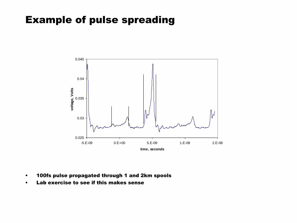
Example of pulse spreading
• 100fs pulse propagated through 1 and 2km spools
• Lab exercise to see if this makes sense
0.025
0.03
0.035
0.04
0.045
-5.E-09 0.E+00 5.E-09 1.E-08 2.E-08
time, seconds
vo
ltag
e,
Vo
lts
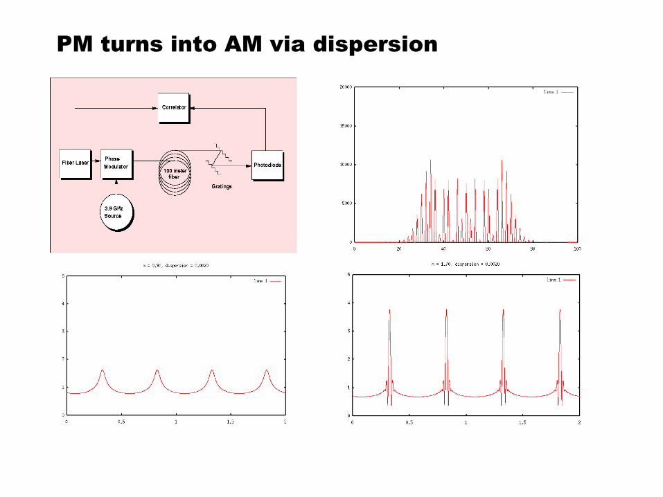
PM turns into AM via dispersion
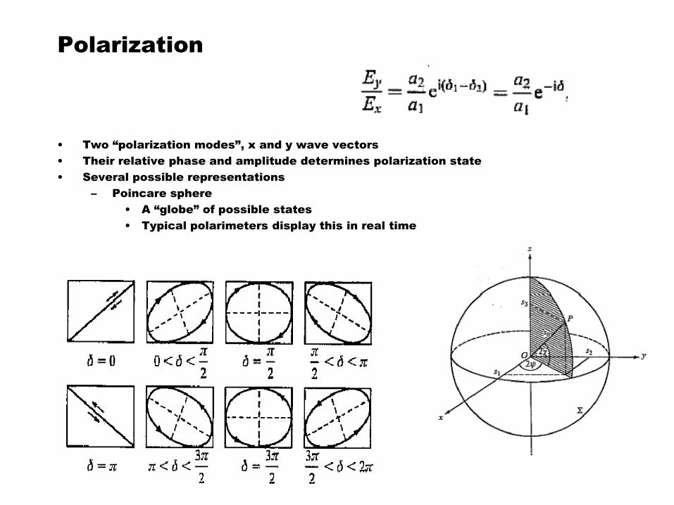
Polarization
• Two “polarization modes”, x and y wave vectors
• Their relative phase and amplitude determines polarization state
• Several possible representations
– Poincare sphere
• A “globe” of possible states
• Typical polarimeters display this in real time
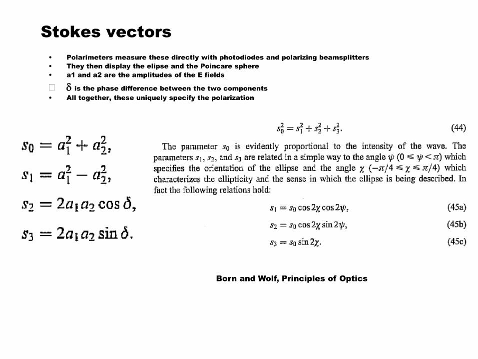
Stokes vectors
• Polarimeters measure these directly with photodiodes and polarizing beamsplitters
• They then display the elipse and the Poincare sphere
• a1 and a2 are the amplitudes of the E fields
d is the phase difference between the two components
• All together, these uniquely specify the polarization
Born and Wolf, Principles of Optics
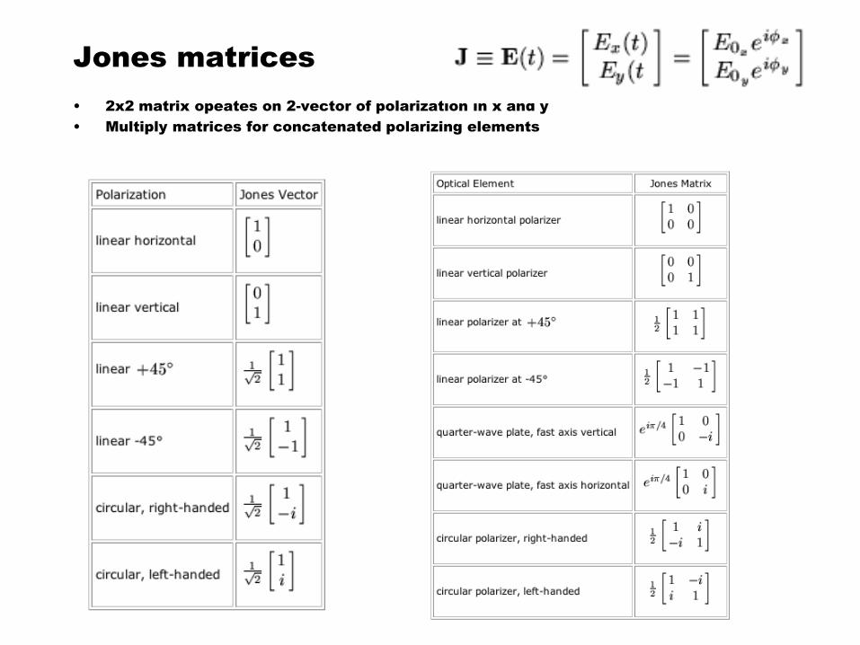
Jones matrices
• 2x2 matrix opeates on 2-vector of polarization in x and y
• Multiply matrices for concatenated polarizing elements
Applications of polarization formalism
• Applications of polarization matrices
– Half and quarter wave retarders
– Polarization controller
– Faraday rotator
– Faraday rotator mirror
• Stress optic effect causes birefringence (waveplate)
– Can be useful, but also a perturbation
• Makes polarization-sensitive components useless, unless…
– Polarization-maintaining fiber (PM), with high birefringence
• Stress birefringence is small compared with intrinsic
– Polarizing fiber (PZ)
• Doesn’t guide one polarization
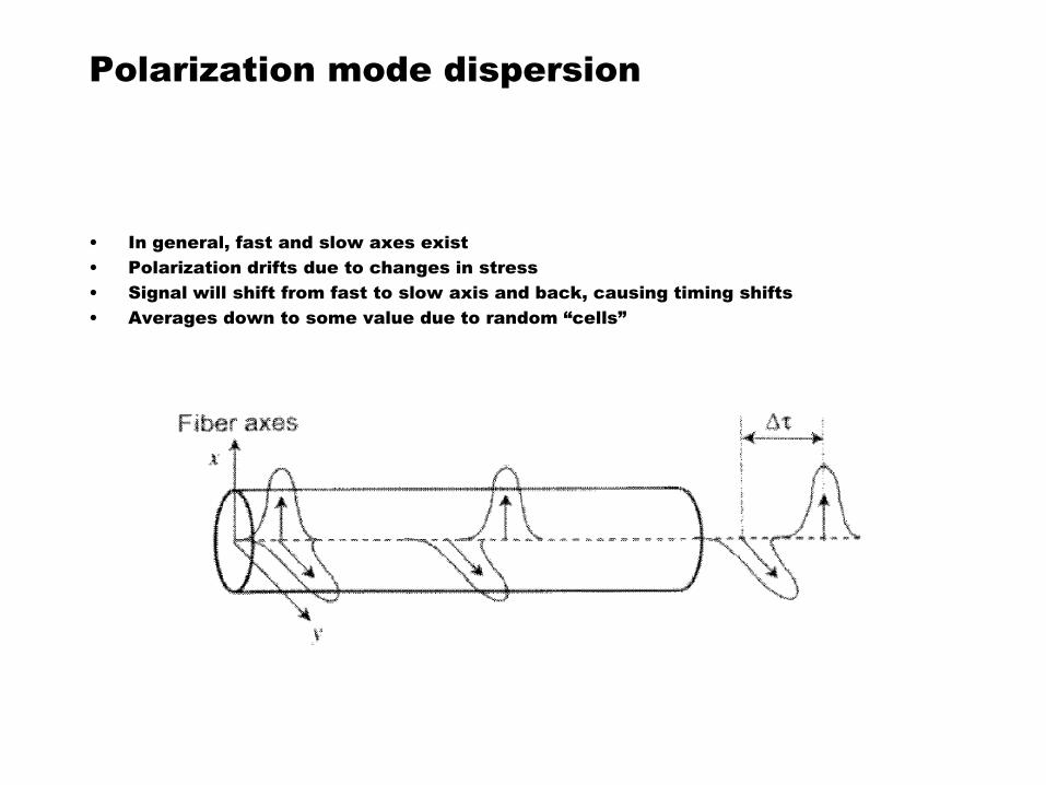
Polarization mode dispersion
• In general, fast and slow axes exist
• Polarization drifts due to changes in stress
• Signal will shift from fast to slow axis and back, causing timing shifts
• Averages down to some value due to random “cells”
Single-mode optical fiber
• Optical waveguides made from transparent material with index step
• Boundary condition imposed by change in index yields modes, as described in RWV
– For our purposes, step index, single-mode fiber is most relevant
• Transverse modes will be ignored, waves treated as one-dimensional
• V-number
• Numerical aperture
• Cutoff wavelength
• Core size
• Index difference
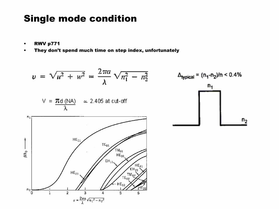
Single mode condition
• RWV p771
• They don’t spend much time on step index, unfortunately
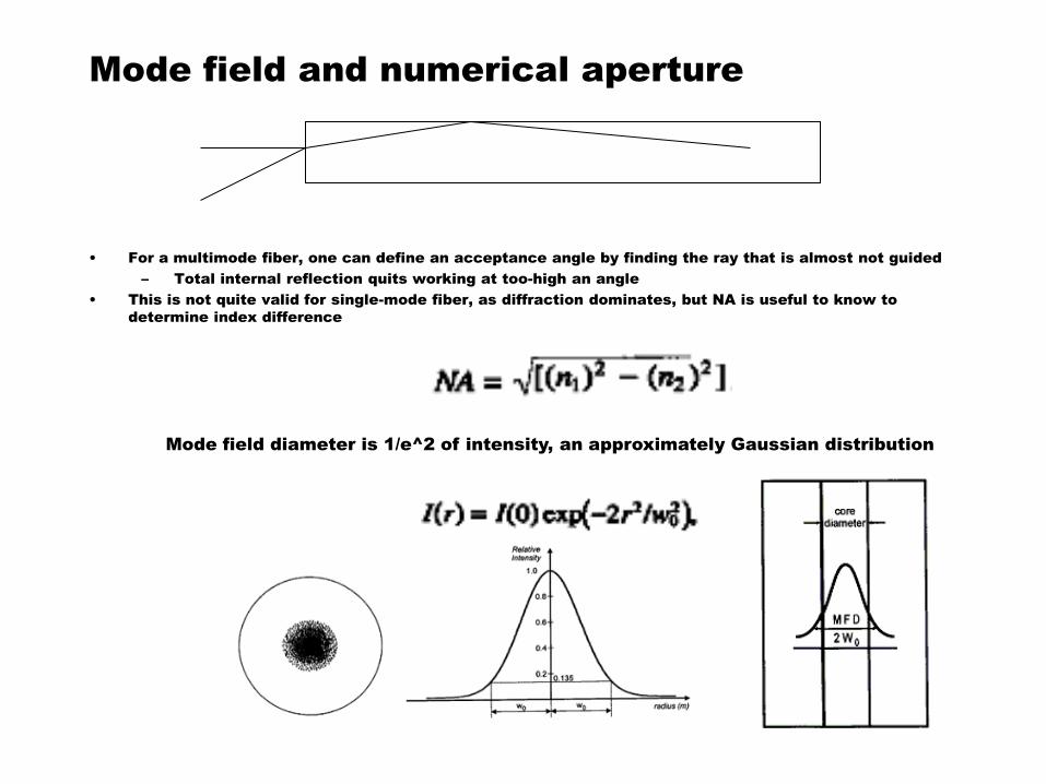
Mode field and numerical aperture
• For a multimode fiber, one can define an acceptance angle by finding the ray that is almost not guided
– Total internal reflection quits working at too-high an angle
• This is not quite valid for single-mode fiber, as diffraction dominates, but NA is useful to know to
determine index difference
Mode field diameter is 1/e^2 of intensity, an approximately Gaussian distribution
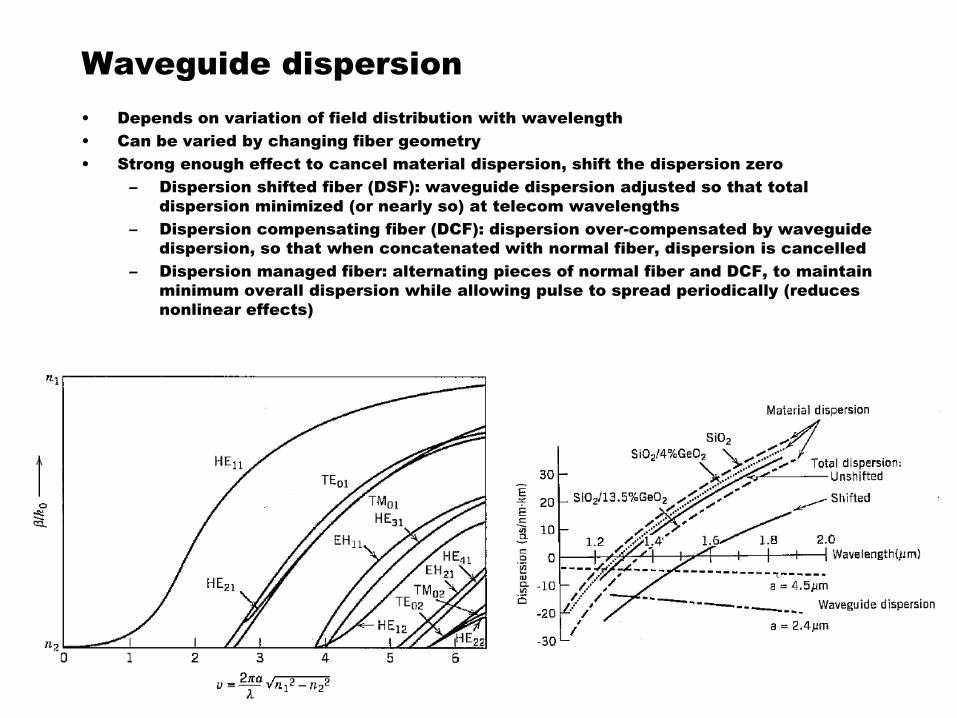
Waveguide dispersion
• Depends on variation of field distribution with wavelength
• Can be varied by changing fiber geometry
• Strong enough effect to cancel material dispersion, shift the dispersion zero
– Dispersion shifted fiber (DSF): waveguide dispersion adjusted so that total
dispersion minimized (or nearly so) at telecom wavelengths
– Dispersion compensating fiber (DCF): dispersion over-compensated by waveguide
dispersion, so that when concatenated with normal fiber, dispersion is cancelled
– Dispersion managed fiber: alternating pieces of normal fiber and DCF, to maintain
minimum overall dispersion while allowing pulse to spread periodically (reduces
nonlinear effects)


![[1] Dielectric-fibre surface waveguides for optical frequencies](https://img.pdfslide.us/doc/110x75/577cd9b91a28ab9e78a40602/1-dielectric-fibre-surface-waveguides-for-optical-frequencies.jpg)