Embed Size (px)
Citation preview
p. 1 ELEC6040 Mobile Radio Communications, Dept. of E.E.E., HKU
Part 2. Cellular System Engineering
p. 2 ELEC6040 Mobile Radio Communications, Dept. of E.E.E., HKU
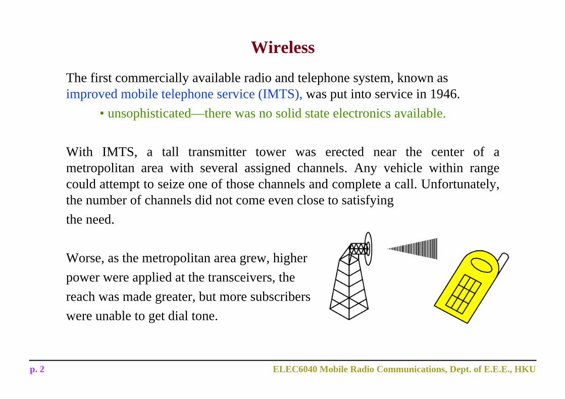
Wireless
The first commercially available radio and telephone system, known as improved mobile telephone service (IMTS), was put into service in 1946.
• unsophisticated—there was no solid state electronics available.
With IMTS, a tall transmitter tower was erected near the center of a metropolitan area with several assigned channels. Any vehicle within range could attempt to seize one of those channels and complete a call. Unfortunately, the number of channels did not come even close to satisfyingthe need.
Worse, as the metropolitan area grew, higherpower were applied at the transceivers, thereach was made greater, but more subscriberswere unable to get dial tone.
p. 3 ELEC6040 Mobile Radio Communications, Dept. of E.E.E., HKU
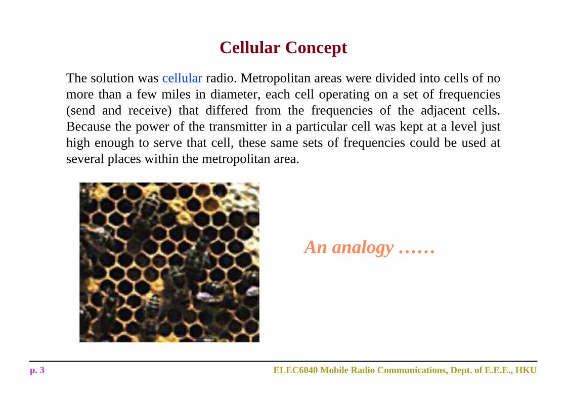
Cellular Concept
The solution was cellular radio. Metropolitan areas were divided into cells of no more than a few miles in diameter, each cell operating on a set of frequencies (send and receive) that differed from the frequencies of the adjacent cells. Because the power of the transmitter in a particular cell was kept at a level just high enough to serve that cell, these same sets of frequencies could be used at several places within the metropolitan area.
An analogy ……

p. 4 ELEC6040 Mobile Radio Communications, Dept. of E.E.E., HKU
Cellular Concept (II)• Cellular concept:
– Each base station is allocated a portion of the total number of frequency channels available to the entire system, and nearby base stations are assigned different groups of channels.
– Neighboring base stations are assigned different groups of channels so that the interference between base stations (and the mobile users under their control) is minimized.
– The available channels may be reused as many times as necessary, so long as the interference is kept below acceptable levels
provide higher capacity• Cell:
– Is a small geographic area in which a group of radio channels is allocated to be used.
• Footprint:– Is the actual radio coverage of a cell and is determined from field
measurements or propagation prediction models.
p. 5 ELEC6040 Mobile Radio Communications, Dept. of E.E.E., HKU
Cellular Concept (III)
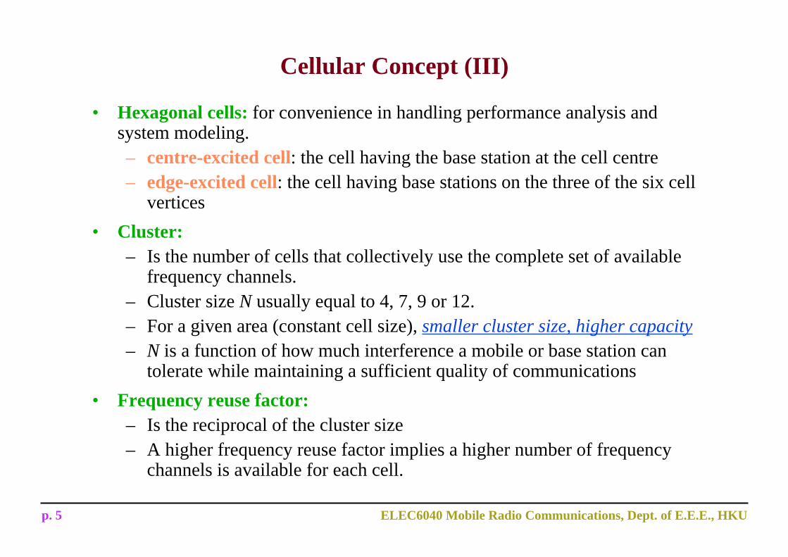
• Hexagonal cells: for convenience in handling performance analysis and system modeling.– centre-excited cell: the cell having the base station at the cell centre– edge-excited cell: the cell having base stations on the three of the six cell
vertices• Cluster:
– Is the number of cells that collectively use the complete set of available frequency channels.
– Cluster size N usually equal to 4, 7, 9 or 12.– For a given area (constant cell size), smaller cluster size, higher capacity– N is a function of how much interference a mobile or base station can
tolerate while maintaining a sufficient quality of communications• Frequency reuse factor:
– Is the reciprocal of the cluster size– A higher frequency reuse factor implies a higher number of frequency
channels is available for each cell.
p. 6 ELEC6040 Mobile Radio Communications, Dept. of E.E.E., HKU
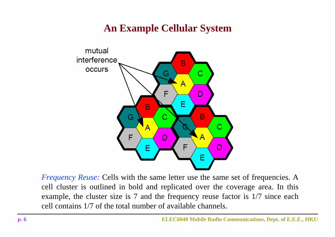
An Example Cellular System
Frequency Reuse: Cells with the same letter use the same set of frequencies. A cell cluster is outlined in bold and replicated over the coverage area. In this example, the cluster size is 7 and the frequency reuse factor is 1/7 since each cell contains 1/7 of the total number of available channels.
p. 7 ELEC6040 Mobile Radio Communications, Dept. of E.E.E., HKU
Allowable Cluster Size
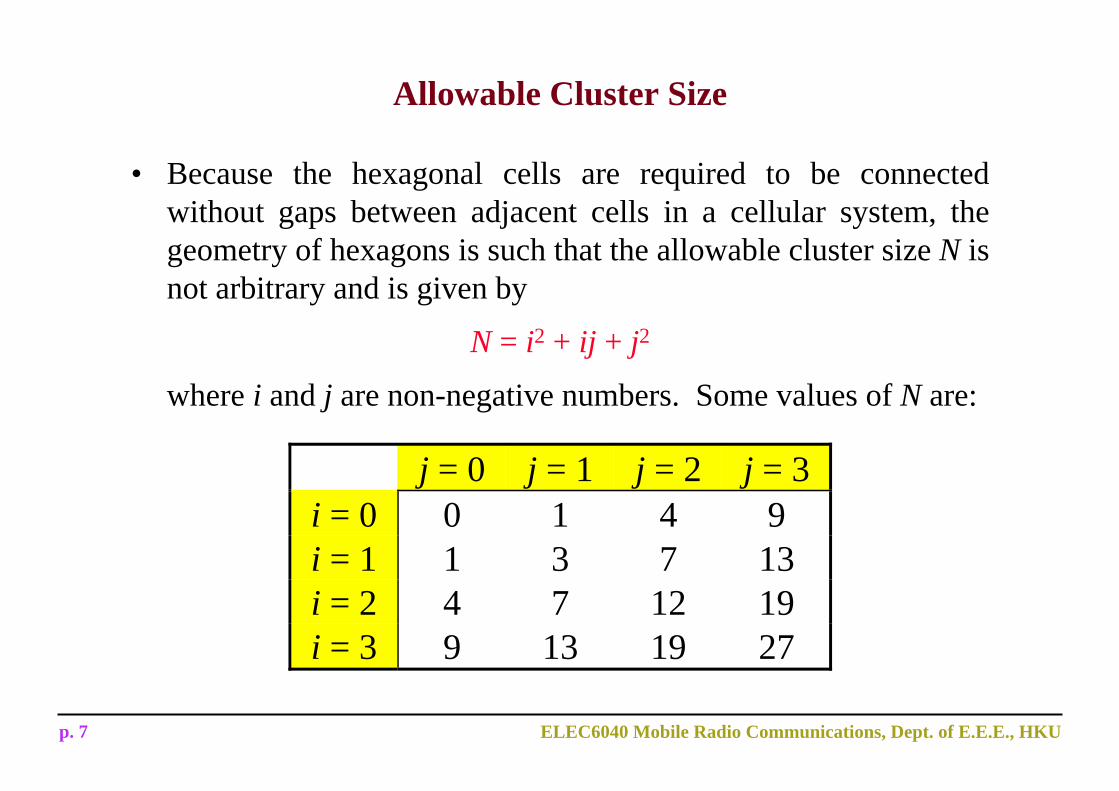
• Because the hexagonal cells are required to be connected without gaps between adjacent cells in a cellular system, the geometry of hexagons is such that the allowable cluster size N is not arbitrary and is given by
N = i2 + ij + j2
where i and j are non-negative numbers. Some values of N are:
j = 0 j = 1 j = 2 j = 3i = 0 0 1 4 9i = 1 1 3 7 13i = 2 4 7 12 19i = 3 9 13 19 27
p. 8 ELEC6040 Mobile Radio Communications, Dept. of E.E.E., HKU
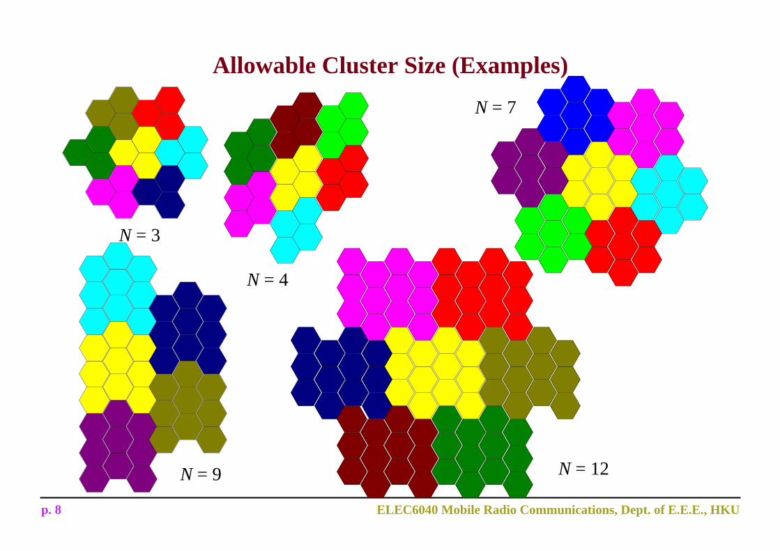
Allowable Cluster Size (Examples)
N = 3
N = 4
N = 9
N = 7
N = 12
p. 9 ELEC6040 Mobile Radio Communications, Dept. of E.E.E., HKU
Channel Assignment• Frequency reuse:
– Objective: increasing capacity while minimizing interference– The design process of selecting and allocating channel groups for all of
the cellular base stations within a system Channel assignment scheme
• Fixed channel assignment:– Each cell is assigned a pre-determined set of frequency channels.– If all the channels are used up, the new calls are blocked.– Variations: borrowing strategy, etc.
• Dynamic channel assignment:– No pre-determined assignment of frequency channels is made.– When a call arrives, the base station ask the mobile switching centre
(MSC) to allocate a channel.– MSC must take into account the co-channel interference in channel
allocation. heavy storage and computational load, lower blocking probability
p. 10 ELEC6040 Mobile Radio Communications, Dept. of E.E.E., HKU
Example
If a total of 33 MHz of bandwidth is allocated to a particular FDD cellular system which uses two 25 kHz simplex channels to provide full duplex voice and control channels, compute the number of channels available per cell if a system uses (a) four-cell reuse; (b) seven cell reuse.
Solution:
Total bandwidth = 33 MHz
Channel bandwidth = 25 KHz x 2 = 50KHz/Duplex channel
Total available channel 33,000/50 =660 channels
For N=4, No of channels available per cell = 660/4 = 165
For N=7, channel allocation could be 5 cells with 94 channels and 2 cells with 95 channels
Source: Rappaport’s Wireless Communications P61
p. 11 ELEC6040 Mobile Radio Communications, Dept. of E.E.E., HKU
Example (Cont.)
If 1 MHz of the allocated spectrum is dedicated to control channels (CC),
determine an equitable distribution of control channels and voice channels
(VC) in each cell for each of the two systems.
Solution:
1 MHz => 1000/50 = 20 CC
For N=4, there are 5 CC and 160 VC per cell. In practice, only 1 CC is
needed per cell. Note that CC have longer reuse distance than VC.
For N=7, the allocation could be 4 cells with 3 CC and 92 VC, 2 cells with 3
CC and 90 VC, and 1cell with 2 CC and 92 VC.
p. 12 ELEC6040 Mobile Radio Communications, Dept. of E.E.E., HKU
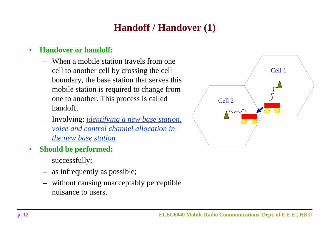
Handoff / Handover (1)
• Handover or handoff:– When a mobile station travels from one
cell to another cell by crossing the cell boundary, the base station that serves this mobile station is required to change from one to another. This process is called handoff.
– Involving: identifying a new base station, voice and control channel allocation in the new base station
• Should be performed:– successfully;– as infrequently as possible;– without causing unacceptably perceptible
nuisance to users.
Cell 1
Cell 2
p. 13 ELEC6040 Mobile Radio Communications, Dept. of E.E.E., HKU
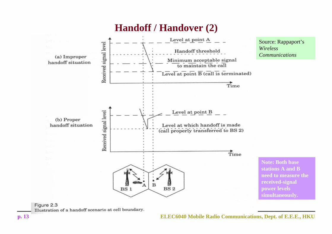
Handoff / Handover (2)Source: Rappaport’sWireless Communications
Note: Both base stations A and B need to measure the received-signal power levels simultaneously.
p. 14 ELEC6040 Mobile Radio Communications, Dept. of E.E.E., HKU
Facts about Handoff (1)
The minimum usable signal level, Pr,min level, for achieving acceptable performance– between -90dBm and -100dBm in the received signal strength for acceptable
voice quality
The margin, Δ, where the threshold power level for initiate handoff, Pr,handoff, is given by Pr,handoff = Pr,min level + Δ.– If Δ is too large, unnecessary handoffs will burden the system.– If Δ is too small, there will be insufficient time to complete a handoff before a
call is lost due to weak signal conditions.
Excessive delay in handoff may occur in crowded situations because:– the system is too busy to do scheduling for many handoff requests;– no spare channel is available in the cell that the mobile enters into.
p. 15 ELEC6040 Mobile Radio Communications, Dept. of E.E.E., HKU
Facts about Handoff (2)
False triggering of handoff due to momentary fading rather than moving away from the base station:– It is important to avoid this situation to occur.– Solution: The base station monitors the received signal strength for a certain
period of time before triggering the handoff procedure.
Mobile assisted handoff– Every mobile station measures the received power from surrounding base stations
and continually reports the measurement results to the serving base station.
Intersystem handoff– Required if a mobile station moves from one cellular system to a different cellular
system.– More complicated.
p. 16 ELEC6040 Mobile Radio Communications, Dept. of E.E.E., HKU
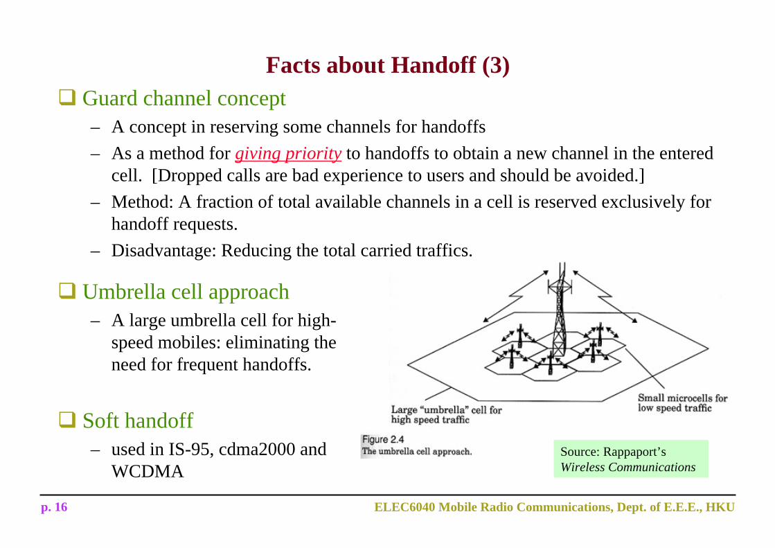
Facts about Handoff (3)Guard channel concept– A concept in reserving some channels for handoffs– As a method for giving priority to handoffs to obtain a new channel in the entered
cell. [Dropped calls are bad experience to users and should be avoided.]– Method: A fraction of total available channels in a cell is reserved exclusively for
handoff requests.– Disadvantage: Reducing the total carried traffics.
Umbrella cell approach– A large umbrella cell for high-
speed mobiles: eliminating the need for frequent handoffs.
Soft handoff– used in IS-95, cdma2000 and
WCDMASource: Rappaport’sWireless Communications
p. 17 ELEC6040 Mobile Radio Communications, Dept. of E.E.E., HKU
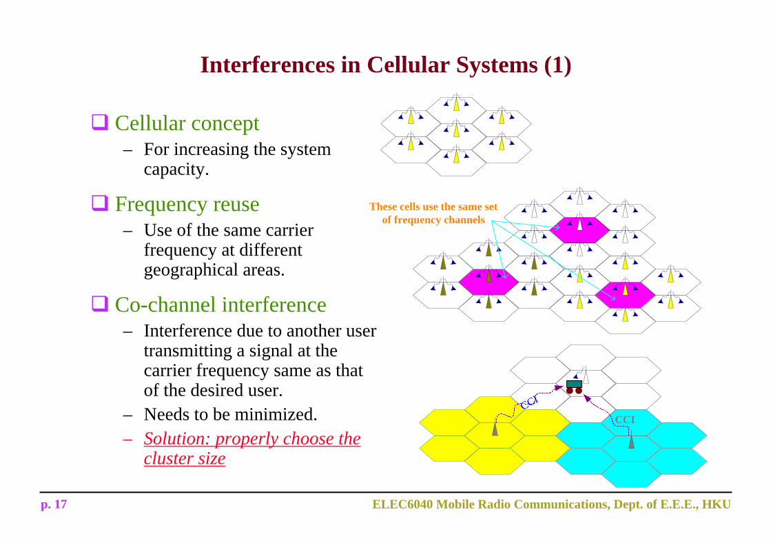
Interferences in Cellular Systems (1)
Cellular concept– For increasing the system
capacity.
Frequency reuse– Use of the same carrier
frequency at different geographical areas.
Co-channel interference– Interference due to another user
transmitting a signal at the carrier frequency same as that of the desired user.
– Needs to be minimized.– Solution: properly choose the
cluster size
These cells use the same setof frequency channels
CCI
CCI
p. 18 ELEC6040 Mobile Radio Communications, Dept. of E.E.E., HKU
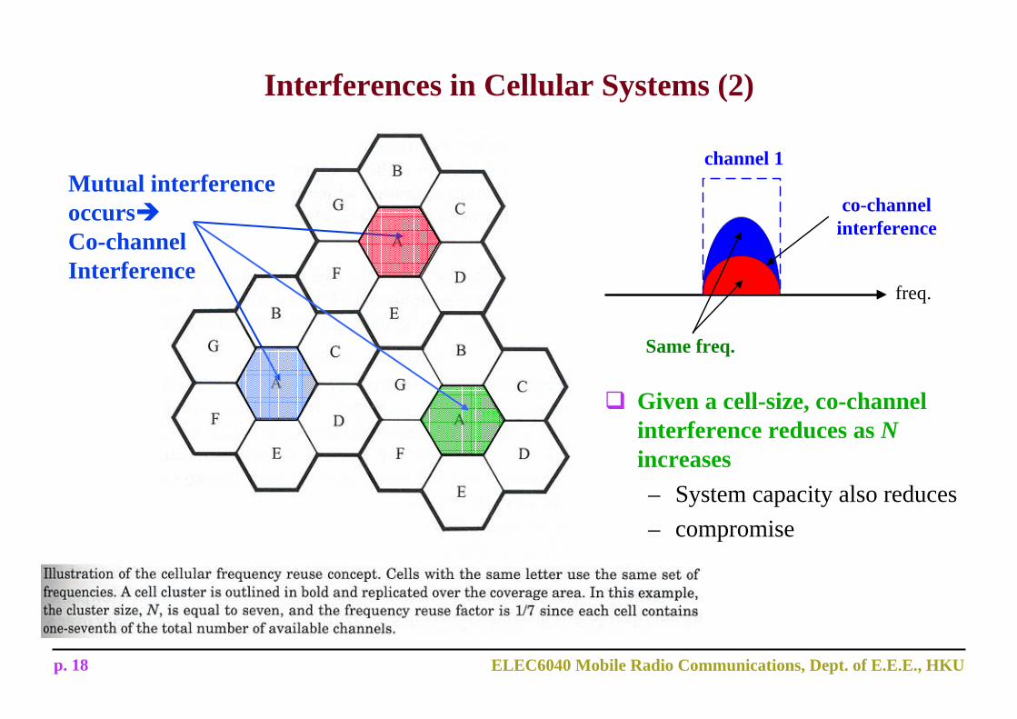
Mutual interference occursCo-channel Interference
Interferences in Cellular Systems (2)
channel 1
co-channelinterference
freq.
Same freq.
Given a cell-size, co-channel interference reduces as Nincreases– System capacity also reduces– compromise

p. 19 ELEC6040 Mobile Radio Communications, Dept. of E.E.E., HKU
Interferences in Cellular Systems (3)
Adjacent channel interference– For signals adjacent in frequency– Resulting from imperfect receiver filters– near-far effect
Solution– improve BPF– channel assignment: adjacent channels assigned to different cells
p. 20 ELEC6040 Mobile Radio Communications, Dept. of E.E.E., HKU
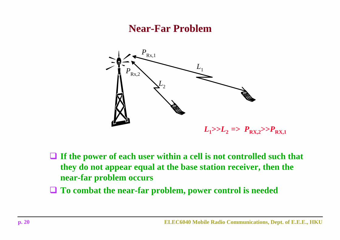
Near-Far Problem
L1
L2
PRx,1
PRx,2
L1>>L2 => PRX,2>>PRX,1
If the power of each user within a cell is not controlled such that they do not appear equal at the base station receiver, then the near-far problem occursTo combat the near-far problem, power control is needed
p. 21 ELEC6040 Mobile Radio Communications, Dept. of E.E.E., HKU
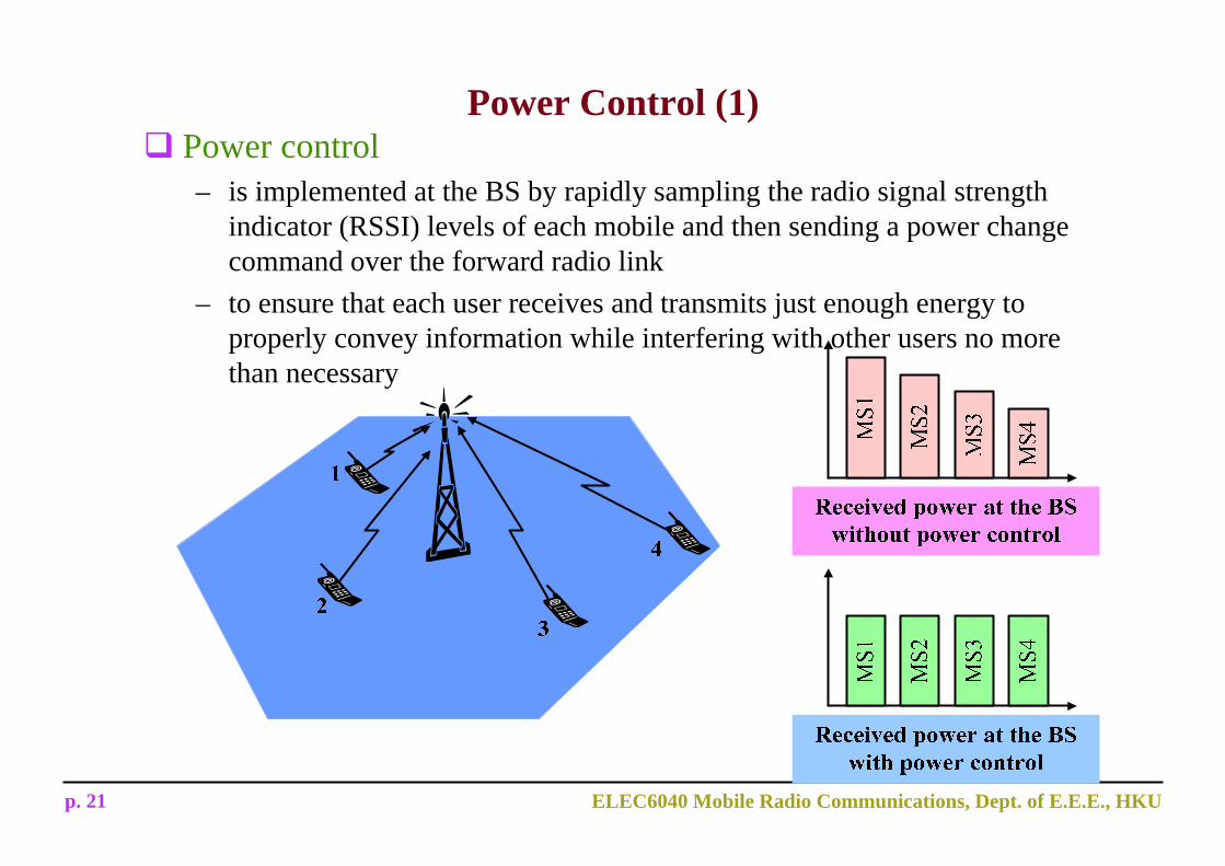
Power Control (1)Power control– is implemented at the BS by rapidly sampling the radio signal strength
indicator (RSSI) levels of each mobile and then sending a power change command over the forward radio link
– to ensure that each user receives and transmits just enough energy to properly convey information while interfering with other users no more than necessary

p. 22 ELEC6040 Mobile Radio Communications, Dept. of E.E.E., HKU
Power Control (2)Advantages:– No transmit power is wasted to obtain a performance better than
necessary => Battery support time is enhanced.– To avoid the near-far effect, since the receiver can be captured by a
received signal having excessively large power.– To reduce co-channel interference impinged on co-channel cells. => To
increase capacity.
Slow power control– The response of the power-control circuit is such that it compensates for
the slowly varying shadowing loss and power loss.
Fast power control– The power-control circuit responds very fast so that the fast Rayleigh
fading can be compensated.– Performance degradation due to channel deep fades effectively avoided.– Employed in 3G.
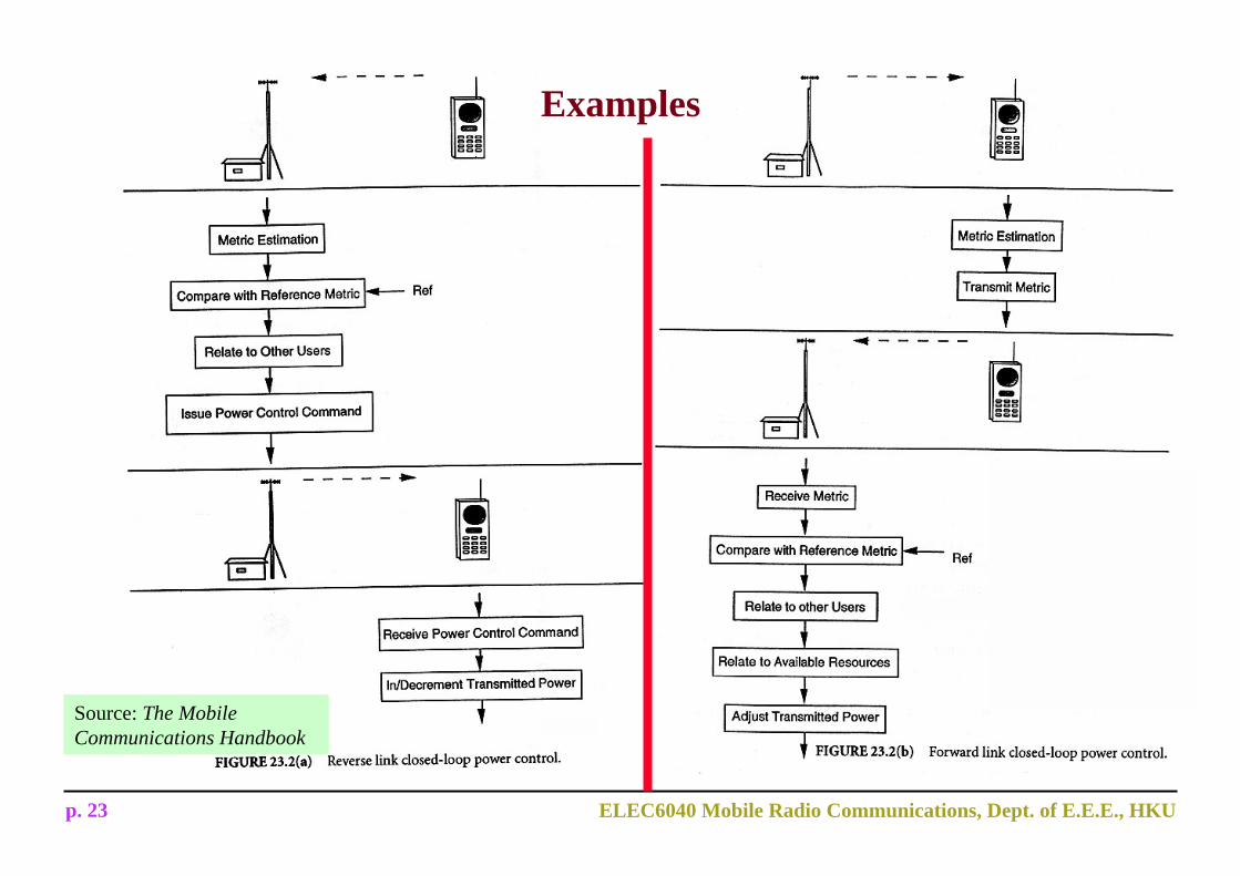
p. 23 ELEC6040 Mobile Radio Communications, Dept. of E.E.E., HKU
Examples
Source: The Mobile Communications Handbook

p. 24 ELEC6040 Mobile Radio Communications, Dept. of E.E.E., HKU
Methods to Enhance the System Capacity — Cell Splitting (1)
Cell splitting:
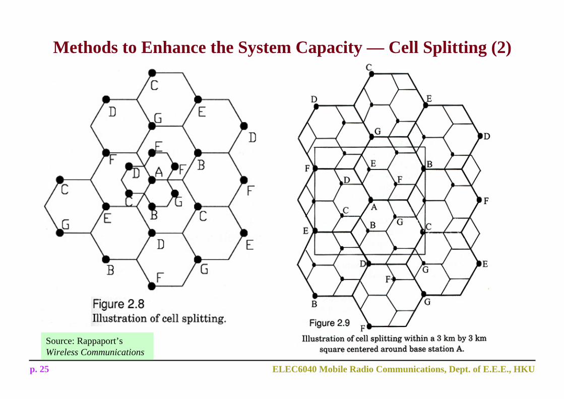
By subdividing a congested cell into smaller cells, each with its own base station and a corresponding reduction in antenna and transmitter power. improving capacity by increasing the number of base stations
Increases the capacity since it increases the number of times the channels are reused.
Good but sometimes it is difficult to find the real estate to house a base station.
p. 25 ELEC6040 Mobile Radio Communications, Dept. of E.E.E., HKU
Methods to Enhance the System Capacity — Cell Splitting (2)
Source: Rappaport’sWireless Communications
p. 26 ELEC6040 Mobile Radio Communications, Dept. of E.E.E., HKU
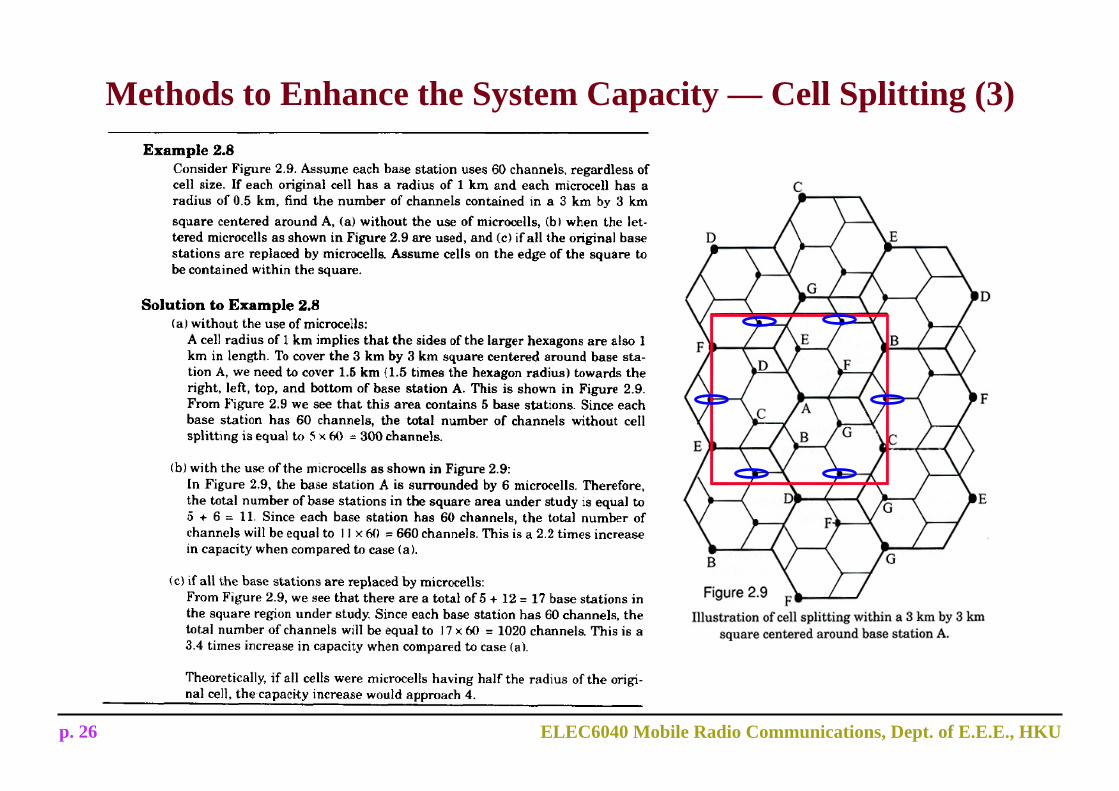
Methods to Enhance the System Capacity — Cell Splitting (3)
p. 27 ELEC6040 Mobile Radio Communications, Dept. of E.E.E., HKU
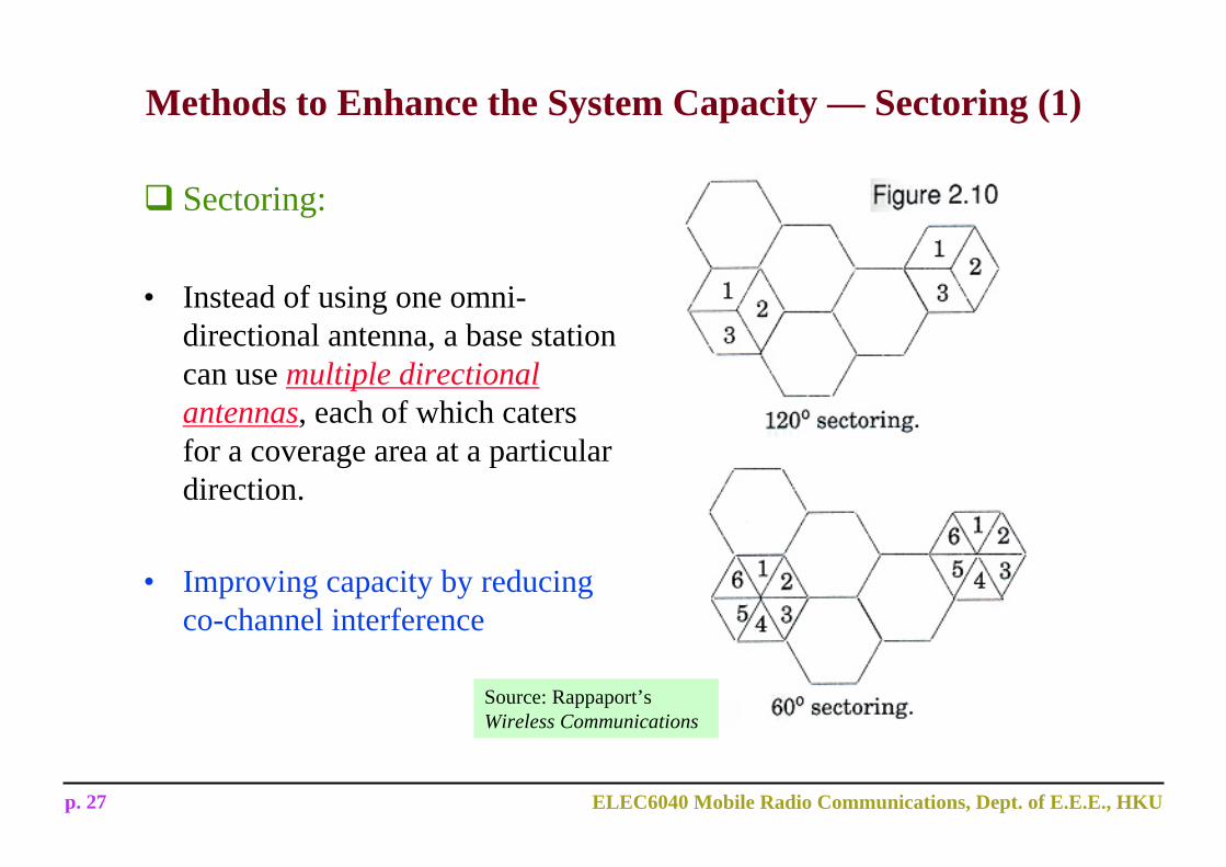
Methods to Enhance the System Capacity — Sectoring (1)
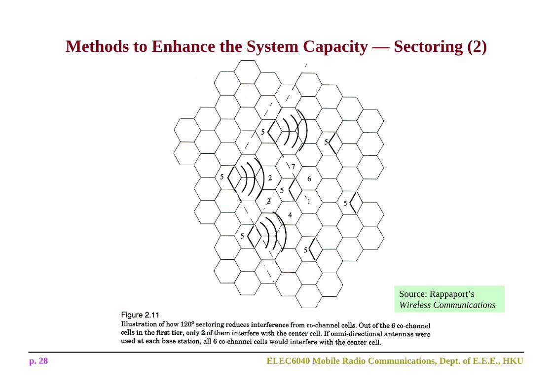
Sectoring:
• Instead of using one omni-directional antenna, a base station can use multiple directional antennas, each of which caters for a coverage area at a particular direction.
• Improving capacity by reducing co-channel interference
Source: Rappaport’sWireless Communications
p. 28 ELEC6040 Mobile Radio Communications, Dept. of E.E.E., HKU
Methods to Enhance the System Capacity — Sectoring (2)
Source: Rappaport’sWireless Communications

p. 29 ELEC6040 Mobile Radio Communications, Dept. of E.E.E., HKU
Methods to Enhance the System Capacity —Lee’s Microcell Zone Concept
• Sectoring increases the number of handoffs and hence increases the load to switching and control subsystems.
• Microcell zone concept is better than sectoring as the burden due to handoff is decreased.
• Same channel is used when the mobile moves from one zone to another.
Source: Rappaport’sWireless Communications

p. 30 ELEC6040 Mobile Radio Communications, Dept. of E.E.E., HKU
Methods to Enhance the System Capacity — Smart AntennaA smart antenna is an array of multiple antennas, say, N antennas, with uniform spacing.Example antenna array
Field strength versus directionSource: http://www.spectrumsignal.com/publications/beamform_primer.pdf
p. 31 ELEC6040 Mobile Radio Communications, Dept. of E.E.E., HKU
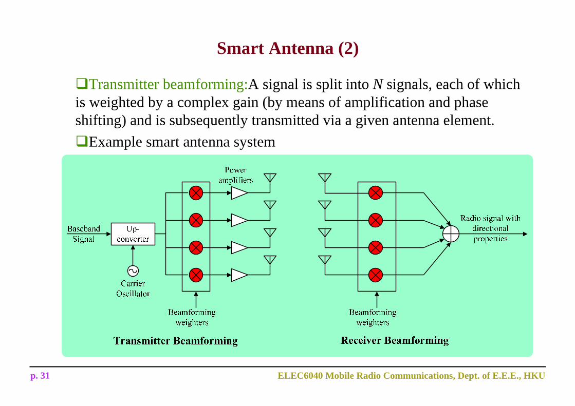
Transmitter beamforming:A signal is split into N signals, each of which is weighted by a complex gain (by means of amplification and phase shifting) and is subsequently transmitted via a given antenna element.
Example smart antenna system
Smart Antenna (2)
p. 32 ELEC6040 Mobile Radio Communications, Dept. of E.E.E., HKU
Smart Antenna (3)
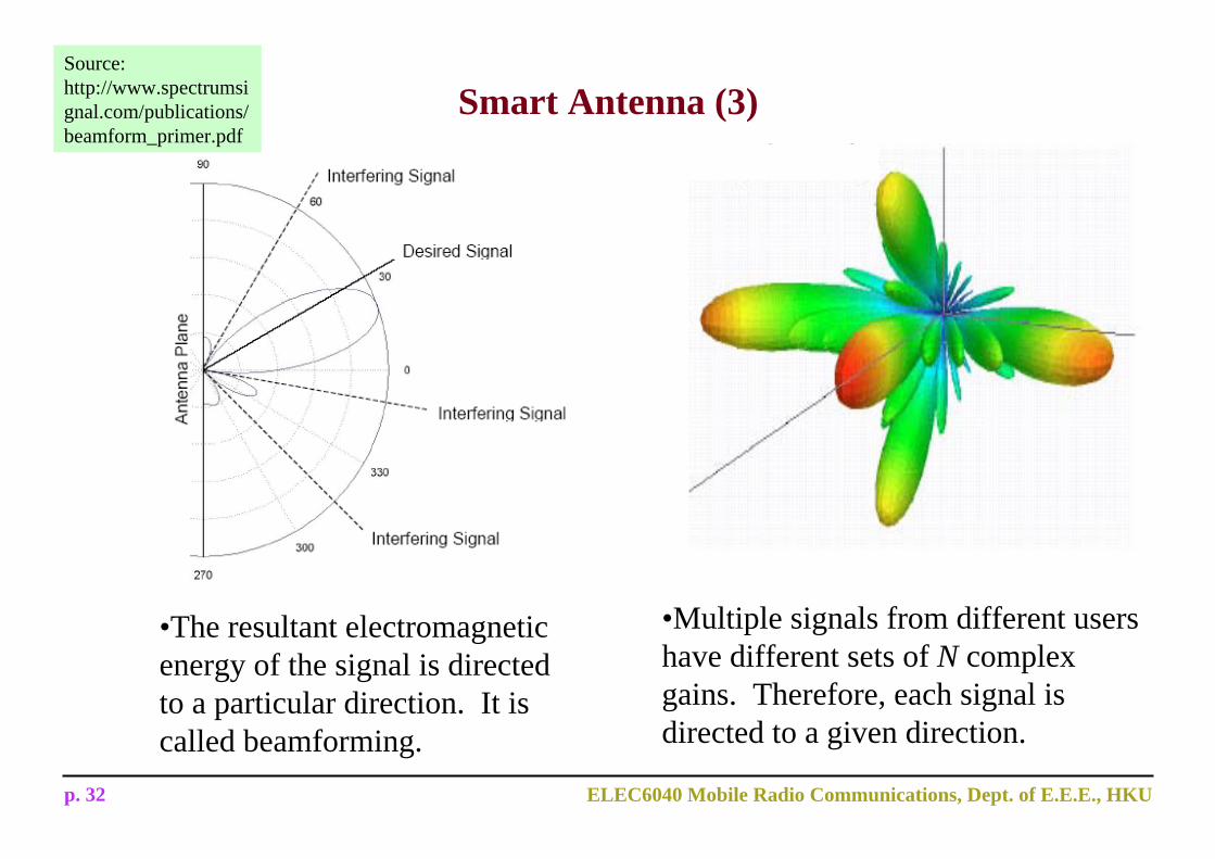
•Multiple signals from different users have different sets of N complex gains. Therefore, each signal is directed to a given direction.
Source: http://www.spectrumsignal.com/publications/beamform_primer.pdf
•The resultant electromagnetic energy of the signal is directed to a particular direction. It is called beamforming.
p. 33 ELEC6040 Mobile Radio Communications, Dept. of E.E.E., HKU
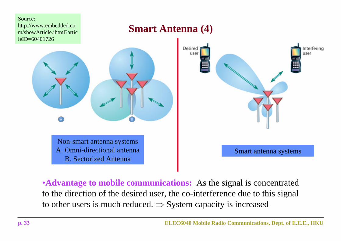
•Advantage to mobile communications: As the signal is concentrated to the direction of the desired user, the co-interference due to this signal to other users is much reduced. ⇒ System capacity is increased
Smart Antenna (4)Source: http://www.embedded.com/showArticle.jhtml?articleID=60401726
Non-smart antenna systems A. Omni-directional antenna
B. Sectorized AntennaSmart antenna systems
p. 34 ELEC6040 Mobile Radio Communications, Dept. of E.E.E., HKU
Source: The Mobile Communications Handbook
Basic Design Steps (1)
Engineering a cellular system to meet the required objectives is not a straight forward task. It demands a great deal of information, such as market demographics, area to be served, traffic offered, and other data not usually available in the earlier stages of system design. As the network evolves, additional statistics will help assess the system performance and re-planning. The main steps in a cellular system design are as follows.
Definition of the Service Area: In general, the responsibility for this step of the project lies on the operating companies and constitutes a tricky task, because it depends on the market demographics and, consequently, on how much the company is willing to invest.
Definition of the Traffic Profile: This step depends on the market demographics and is estimated by taking into account the number of potential subscribers within the services area.
p. 35 ELEC6040 Mobile Radio Communications, Dept. of E.E.E., HKU
Basic Design Steps (2)
Choice of Reuse Pattern: Given the traffic distribution and the interference requirements, a choice of the reuse pattern is carried out.
Location of the Base Station: The location of the first base station constitutes an important step. A significant parameter to be taken into account in this is the relevance of the region to be served. The base station location is chosen so as to be at the center of or as close as possible to the target region. Data, such as available infrastructure and land, as well as local regulations are taken into consideration in this step. The cell radius is defined as a function of the traffic distribution. In urban areas, where the traffic is more heavily concentrated, smaller cells are chosen so as to meet the demand with the available channels. In suburban and in rural areas, the radius is chosen to be large because the traffic demand trends to be small. Once the placement of the first base station has been defined, the others will be accommodated in accordance with the reuse pattern chosen.
p. 36 ELEC6040 Mobile Radio Communications, Dept. of E.E.E., HKU
Radio Coverage Prediction: Given the topography and the morphology of the terrain, a radio prediction algorithm, implemented in the computer, is used to predict the signal strength in the geographic region. An alternative to this relies on field measurements with the use of appropriate equipment. The first option is usually less costly and is widely used.
Design Checkup: At this point it is necessary to check whether or not the parameters with which the system has been designed satisfy the requirements. For instance, it may be necessary to re-evaluate the base station location, the antenna height, etc., so that better performance can be attained.
Field Measurements: For a better tuning of the parameters involved, field measurements (radio survey) should be included in the design. This can be carried out with transmitters and towers provisionally set up at the locations initially defined for the base station. The cost assessment may require that a redesign of the system should be carried out.
Basic Design Steps (3)
p. 37 ELEC6040 Mobile Radio Communications, Dept. of E.E.E., HKU
Some Factors Considered in Cellular Planning
Desired signal-to-interference ratio– E.g., 18dB considered acceptable for voice transmission in AMPS– Is affected by the co-channel interference (a result of other users using
the same carrier frequency) and adjacent channel interference (a result of receiver RF filter’s unsharp response).
– Affects the frequency reuse factor.
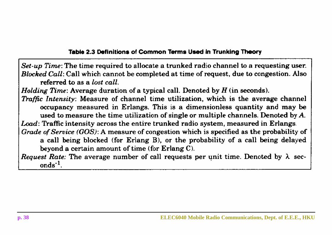
How to accommodate a large number of users in a limited radio spectrum– Trunking: each user is allocated a channel on a per call basis– Erlang: a measure of traffic intensity; one Erlang represents the amount
of traffic intensity carried by a channel that is completely occupied– Example: a radio channel that is occupied for 30 minutes during an hour
carries 0.5 Erlang traffic
p. 38 ELEC6040 Mobile Radio Communications, Dept. of E.E.E., HKU