Embed Size (px)
Citation preview

Copyright © 2006 IEEE. All rights reserved. 1
IEEE Standard forInformation technology—Telecommunications and information
exchange between systems—Local and metropolitan area networks—Specific requirements—
Part 15.4: Wireless Medium Access Control (MAC) and Physical Layer (PHY) Specifications for Low-Rate Wireless Personal Area Networks (WPANs)
1. Overview
1.1 General
Wireless personal area networks (WPANs) are used to convey information over relatively short distances.Unlike wireless local area networks (WLANs), connections effected via WPANs involve little or noinfrastructure. This feature allows small, power-efficient, inexpensive solutions to be implemented for awide range of devices.
This document defines a standard for a low-rate WPAN (LR-WPAN).
1.2 Scope
The scope of this revision is to produce specific enhancements and corrections to IEEE Std 802.15.4, all ofwhich will be backwards compatible with IEEE Std 802.15.4-2003. These enhancements and correctionsinclude resolving ambiguities, reducing unnecessary complexity, increasing flexibility in security key usage,considerations for newly available frequency allocations, and others.
IEEE Std 802.15.4 defines the physical layer (PHY) and medium access control (MAC) sublayerspecifications for low-data-rate wireless connectivity with fixed, portable, and moving devices with nobattery or very limited battery consumption requirements typically operating in the personal operating space(POS) of 10 m. It is foreseen that, depending on the application, a longer range at a lower data rate may bean acceptable tradeoff.

IEEEStd 802.15.4-2006 LOCAL AND METROPOLITAN AREA NETWORKS—PART 15.4:
2 Copyright © 2006 IEEE. All rights reserved.
It is the intent of this revision to work toward a level of coexistence with other wireless devices inconjunction with Coexistence Task Groups, such as IEEE 802.15.2 and IEEE 802.11/ETSI-BRAN/MMAC5GSG.
1.3 Purpose
The purpose of this revision is to extend the market applicability of IEEE Std 802.15.4 and to removeambiguities in the standard. Implementations of the 2003 edition of this standard have revealed potentialareas of improvements. Additional frequency bands are being made available in various countries that areattractive for this application space.

IEEEWIRELESS MAC AND PHY SPECIFICATIONS FOR LR-WPANS Std 802.15.4-2006
Copyright © 2006 IEEE. All rights reserved. 3
2. Normative references
The following referenced documents are indispensable for the application of this document. For datedreferences, only the edition cited applies. For undated references, the latest edition of the referenceddocument (including any amendments or corrigenda) applies.
FIPS Pub 197, Advanced Encryption Standard (AES).1
IEEE Std 802®, IEEE Standards for Local and Metropolitan Area Networks: Overview and Architecture.2
ISO/IEC 8802-2 (IEEE Std 802.2™), Information technology — Telecommunications and informationexchange between systems — Local and metropolitan area networks — Specific requirements — Part 2:Logical link control.3
ISO/IEC 9646-7 (ITU-T Rec. X.296), Information technology — Open systems interconnection —Conformance testing methodology and framework — Part 7: Implementation conformance statements.
1FIPS publications are available from the National Technical Information Service (NTIS), U. S. Dept. of Commerce, 5285 Port RoyalRd., Springfield, VA 22161 (http://www.ntis.org/).2IEEE Publications are available from the Institute of Electrical and Electronics Engineers, 445 Hoes Lane, Piscataway, NJ 08854,USA (http://standards.ieee.org).3ISO/IEC publications are available from the ISO Central Secretariat, Case Postale 56, 1 rue de Varembé, CH-1211, Genève 20,Switzerland/Suisse (http://www.iso.ch/). ISO/IEC publications are also available in the United States from Global EngineeringDocuments, 15 Inverness Way East, Englewood, Colorado 80112, USA (http://global.ihs.com/). Electronic copies are available in theUnited States from the American National Standards Institute, 25 West 43rd Street, 4th Floor, New York, NY 10036, USA (http://www.ansi.org/).

IEEEStd 802.15.4-2006 LOCAL AND METROPOLITAN AREA NETWORKS—PART 15.4:
4 Copyright © 2006 IEEE. All rights reserved.

IEEEWIRELESS MAC AND PHY SPECIFICATIONS FOR LR-WPANS Std 802.15.4-2006
Copyright © 2006 IEEE. All rights reserved. 5
3. Definitions
For the purposes of this standard, the following terms and definitions apply. Terms not defined in this clausecan be found in the The Authoritative Dictionary of IEEE Standards Terms, Seventh Edition [B3].4
3.1 alternate personal area network (PAN) coordinator: A coordinator that is capable of replacing thePAN coordinator, if the PAN coordinator leaves the network for any reason. A PAN can have zero or morealternate PAN coordinators.
3.2 association: The service used to establish membership for a device in a wireless personal area network(WPAN).
3.3 authentication tag: Information that allows the verification of authenticity of a message.
3.4 beacon-enabled personal area network (PAN): A PAN in which all coordinators emit regularbeacons, i.e., have beacon order < 0x0F.
3.5 block cipher: A cryptographic function that operates on strings of fixed size.
3.6 block size: The size, in bits, of the strings on which a block cipher operates.
3.7 contention access period (CAP): The period of time immediately following a beacon frame duringwhich devices wishing to transmit will compete for channel access using a slotted carrier sense multipleaccess with collision avoidance (CSMA-CA) mechanism.
3.8 contention access period (CAP) symbol: A symbol period occurring during the CAP.
3.9 coordinator: A full-function device (FFD) capable of relaying messages. If a coordinator is theprincipal controller of a personal area network (PAN), it is called the PAN coordinator.
3.10 data authentication: The process whereby an entity receiving a message corroborates evidence aboutthe true source of the information in the message and, thereby, evidence that the message has not beenmodified in transit.
3.11 data authenticity: Assurance about the source of information.
3.12 device: Any entity containing an implementation of the IEEE 802.15.4 medium access control (MAC)and physical interface to the wireless medium. A device may be a reduced-function device (RFD) or a full-function device (FFD).
3.13 encryption: The transformation of a message into a new representation so that privileged informationis required to recover the original representation.
3.14 frame: The format of aggregated bits from a medium access control (MAC) sublayer entity that aretransmitted together in time.
3.15 full-function device (FFD): A device capable of operating as a coordinator.
3.16 group key: A key that is known only to a set of devices.
3.17 idle period: A duration of time where no transceiver activity is scheduled to take place.
4The numbers in brackets correspond to the numbers of the bibliography in Annex G.

IEEEStd 802.15.4-2006 LOCAL AND METROPOLITAN AREA NETWORKS—PART 15.4:
6 Copyright © 2006 IEEE. All rights reserved.
3.18 key: Privileged information that may be used, for example, to protect information from disclosure to,and/or undetectable modification by, parties that do not have access to this privileged information.
3.19 key establishment: A process whereby two or more parties establish a key.
3.20 keying material: The combination of a key and associated security information (e.g., a nonce value).
3.21 key management: The collection of processes for the establishment and maintenance of keyingrelationships over a system’s lifetime.
3.22 key sharing group: A set of devices that share a key.
3.23 local clock: The symbol clock internal to a device.
3.24 link key: A secret key that is shared between precisely two devices.
3.25 minimum security level: Indication of minimum protection required on information in transit.
3.26 mobile device: A device whose logical location in the network may change during use.
3.27 m-sequence: Maximal length linear feedback shift register sequence.
3.28 nonbeacon-enabled personal area network (PAN): A PAN in which coordinators do not emit regularbeacons, i.e., have beacon order = 0x0F.
3.29 nonce: A nonrepeating value, such as an increasing counter, a sufficiently long random string, or atimestamp.
3.30 orphaned device: A device that has lost contact with its associated coordinator.
3.31 packet: The formatted, aggregated bits that are transmitted together in time across the physicalmedium.
3.32 payload data: The contents of a data message that is being transmitted.
3.33 personal area network (PAN) coordinator: A coordinator that is the principal controller of a PAN.An IEEE 802.15.4 network has exactly one PAN coordinator.
3.34 personal operating space (POS): The space about a person or object that is typically about 10 m in alldirections and envelops the person or object whether stationary or in motion.
3.35 plain text: A string of unscrambled information.
3.36 protection: The combination of security services provided for information in transit, such asconfidentiality, data authenticity, and/or replay protection.
3.37 radio sphere of influence: The region of space throughout which a radio may successfullycommunicate with other like radios.
3.38 reduced-function device (RFD): A device that is not capable of operating as a coordinator.
3.39 security level: Indication of purported protection applied to information in transit.

IEEEWIRELESS MAC AND PHY SPECIFICATIONS FOR LR-WPANS Std 802.15.4-2006
Copyright © 2006 IEEE. All rights reserved. 7
3.40 self-healing: The ability of the network to detect, and recover from, faults appearing in either networknodes or communication links, without human intervention.
3.41 self-organizing: The ability of network nodes to detect the presence of other nodes and to organize intoa structured, functioning network without human intervention.
3.42 symmetric key: A secret key that is shared between two or more parties that may be used forencryption/decryption or integrity protection/integrity verification, depending on its intended use.
3.43 transaction: The exchange of related, consecutive frames between two peer medium access control(MAC) entities, required for a successful transmission of a MAC command or data frame.
3.44 transaction queue: A list of the pending transactions, which are to be sent using indirect transmission,that are initiated by the medium access control (MAC) sublayer of a given coordinator. The transactionqueue is maintained by that coordinator while the transactions are in progress, and its length isimplementation-dependent but must be at least one.

IEEEStd 802.15.4-2006 LOCAL AND METROPOLITAN AREA NETWORKS—PART 15.4:
8 Copyright © 2006 IEEE. All rights reserved.

IEEEWIRELESS MAC AND PHY SPECIFICATIONS FOR LR-WPANS Std 802.15.4-2006
Copyright © 2006 IEEE. All rights reserved. 9
4. Acronyms and abbreviations
AES advanced encryption standardASK amplitude shift keyingAWGN additive white Gaussian noiseAWN affected wireless networkBE backoff exponentBER bit error rateBI beacon intervalBLE battery life extensionBO beacon orderBPSK binary phase-shift keyingBSN beacon sequence numberCAP contention access periodCBC-MAC cipher block chaining message authentication codeCCA clear channel assessmentCCM counter with CBC-MAC (mode of operation)CCM* extension of CCMCFP contention-free periodCRC cyclic redundancy checkCSMA-CA carrier sense multiple access with collision avoidanceCTR counter modeCW contention window (length)DSN data sequence numberDSSS direct sequence spread spectrumED energy detectionEIRP effective isotropic radiated powerEMC electromagnetic compatibilityERP effective radiated powerEVM error-vector magnitudeFCS frame check sequenceFFD full-function deviceFH frequency hoppingFHSS frequency hopping spread spectrumGTS guaranteed time slotIFS interframe space or spacingISM industrial, scientific, and medicalIUT implementation under testIWN interfering wireless networkLIFS long interframe spacingLLC logical link controlLQI link quality indicationLPDU LLC protocol data unitLR-WPAN low-rate wireless personal area networkLSB least significant bitMAC medium access control

IEEEStd 802.15.4-2006 LOCAL AND METROPOLITAN AREA NETWORKS—PART 15.4:
10 Copyright © 2006 IEEE. All rights reserved.
MCPS MAC common part sublayerMCPS-SAP MAC common part sublayer service access pointMFR MAC footerMHR MAC headerMIC message integrity codeMLME MAC sublayer management entityMLME-SAP MAC sublayer management entity service access pointMSB most significant bitMPDU MAC protocol data unitMSDU MAC service data unitNB number of backoff (periods)OCDM orthogonal code division multiplexingO-QPSK offset quadrature phase-shift keyingOSI open systems interconnectionPAN personal area networkPC personal computerPD PHY dataPD-SAP PHY data service access pointPER packet error ratePHR PHY headerPHY physical layerPIB PAN information basePICS protocol implementation conformance statementPLME physical layer management entityPLME-SAP physical layer management entity service access pointPN pseudo-random noisePOS personal operating spacePPDU PHY protocol data unitPSD power spectral densityPSDU PHY service data unitPSSS parallel sequence spread spectrumRF radio frequencyRFD reduced-function deviceRX receive or receiverSD superframe durationSER symbol error rateSFD start-of-frame delimiterSHR synchronization headerSIFS short interframe spacingSIR signal-to-interference ratioSNR sygnal-to-noise ratioSO superframe orderSPDU SSCS protocol data unitsSRD short-range deviceSSCS service-specific convergence sublayerSUT system under test

IEEEWIRELESS MAC AND PHY SPECIFICATIONS FOR LR-WPANS Std 802.15.4-2006
Copyright © 2006 IEEE. All rights reserved. 11
TRX transceiverTX transmit or transmitterWLAN wireless local area networkWPAN wireless personal area network

IEEEStd 802.15.4-2006 LOCAL AND METROPOLITAN AREA NETWORKS—PART 15.4:
12 Copyright © 2006 IEEE. All rights reserved.

IEEEWIRELESS MAC AND PHY SPECIFICATIONS FOR LR-WPANS Std 802.15.4-2006
Copyright © 2006 IEEE. All rights reserved. 13
5. General description
5.1 Introduction
An LR-WPAN is a simple, low-cost communication network that allows wireless connectivity inapplications with limited power and relaxed throughput requirements. The main objectives of an LR-WPANare ease of installation, reliable data transfer, short-range operation, extremely low cost, and a reasonablebattery life, while maintaining a simple and flexible protocol.
Some of the characteristics of an LR-WPAN are as follows:
— Over-the-air data rates of 250 kb/s, 100kb/s, 40 kb/s, and 20 kb/s
— Star or peer-to-peer operation
— Allocated 16-bit short or 64-bit extended addresses
— Optional allocation of guaranteed time slots (GTSs)
— Carrier sense multiple access with collision avoidance (CSMA-CA) channel access
— Fully acknowledged protocol for transfer reliability
— Low power consumption
— Energy detection (ED)
— Link quality indication (LQI)
— 16 channels in the 2450 MHz band, 30 channels in the 915 MHz band, and 3 channels in the868 MHz band
Two different device types can participate in an IEEE 802.15.4 network; a full-function device (FFD) and areduced-function device (RFD). The FFD can operate in three modes serving as a personal area network(PAN) coordinator, a coordinator, or a device. An FFD can talk to RFDs or other FFDs, while an RFD cantalk only to an FFD. An RFD is intended for applications that are extremely simple, such as a light switch ora passive infrared sensor; they do not have the need to send large amounts of data and may only associatewith a single FFD at a time. Consequently, the RFD can be implemented using minimal resources andmemory capacity.
This standard is backward-compatible to the 2003 edition; in other words, devices conforming to thisstandard are capable of joining and functioning in a PAN composed of devices conforming toIEEE Std 802.15.4-2003.
5.2 Components of the IEEE 802.15.4 WPAN
A system conforming to this standard consists of several components. The most basic is the device. A devicemay be an RFD or an FFD. Two or more devices within a POS communicating on the same physical channelconstitute a WPAN. However, this WPAN shall include at least one FFD, operating as the PAN coordinator.
An IEEE 802.15.4 network is part of the WPAN family of standards although the coverage of the networkmay extend beyond the POS, which typically defines the WPAN.
A well-defined coverage area does not exist for wireless media because propagation characteristics aredynamic and uncertain. Small changes in position or direction may result in drastic differences in the signalstrength or quality of the communication link. These effects occur whether a device is stationary or mobile,as moving objects may impact station-to-station propagation.

IEEEStd 802.15.4-2006 LOCAL AND METROPOLITAN AREA NETWORKS—PART 15.4:
14 Copyright © 2006 IEEE. All rights reserved.
5.3 Network topologies
Depending on the application requirements, an IEEE 802.15.4 LR-WPAN may operate in either of twotopologies: the star topology or the peer-to-peer topology. Both are shown in Figure 1. In the star topologythe communication is established between devices and a single central controller, called the PANcoordinator. A device typically has some associated application and is either the initiation point or thetermination point for network communications. A PAN coordinator may also have a specific application, butit can be used to initiate, terminate, or route communication around the network. The PAN coordinator is theprimary controller of the PAN. All devices operating on a network of either topology shall have unique 64-bit addresses. This address may be used for direct communication within the PAN, or a short address may beallocated by the PAN coordinator when the device associates and used instead. The PAN coordinator mightoften be mains powered, while the devices will most likely be battery powered. Applications that benefitfrom a star topology include home automation, personal computer (PC) peripherals, toys and games, andpersonal health care.
The peer-to-peer topology also has a PAN coordinator; however, it differs from the star topology in that anydevice may communicate with any other device as long as they are in range of one another. Peer-to-peertopology allows more complex network formations to be implemented, such as mesh networking topology.Applications such as industrial control and monitoring, wireless sensor networks, asset and inventorytracking, intelligent agriculture, and security would benefit from such a network topology. A peer-to-peernetwork can be ad hoc, self-organizing, and self-healing. It may also allow multiple hops to route messagesfrom any device to any other device on the network. Such functions can be added at the higher layer, but arenot part of this standard.
Each independent PAN selects a unique identifier. This PAN identifier allows communication betweendevices within a network using short addresses and enables transmissions between devices acrossindependent networks. The mechanism by which identifiers are chosen is outside the scope of this standard.
The network formation is performed by the higher layer, which is not part of this standard. However, 5.3.1and 5.3.2 provide a brief overview on how each supported topology can be formed.
5.3.1 Star network formation
The basic structure of a star network is illustrated in Figure 1. After an FFD is activated, it can establish itsown network and become the PAN coordinator. All star networks operate independently from all other starnetworks currently in operation. This is achieved by choosing a PAN identifier that is not currently used byany other network within the radio sphere of influence. Once the PAN identifier is chosen, the PAN
Figure 1—Star and peer-to-peer topology examples
Reduced Function DeviceFull Function Device
Star Topology Peer-to-Peer Topology
PANCoordinator
Communication Flow
PANCoordinator

IEEEWIRELESS MAC AND PHY SPECIFICATIONS FOR LR-WPANS Std 802.15.4-2006
Copyright © 2006 IEEE. All rights reserved. 15
coordinator allows other devices, potentially both FFDs and RFDs, to join its network. The higher layer canuse the procedures described in 7.5.2 and 7.5.3 to form a star network.
5.3.2 Peer-to-peer network formation
In a peer-to-peer topology, each device is capable of communicating with any other device within its radiosphere of influence. One device is nominated as the PAN coordinator, for instance, by virtue of being thefirst device to communicate on the channel. Further network structures are constructed out of the peer-to-peer topology and it is possible to impose topological restrictions on the formation of the network.
An example of the use of the peer-to-peer communications topology is the cluster tree. The cluster treenetwork is a special case of a peer-to-peer network in which most devices are FFDs. An RFD connects to acluster tree network as a leaf device at the end of a branch because RFDs do not allow other devices toassociate. Any of the FFDs may act as a coordinator and provide synchronization services to other devicesor other coordinators. Only one of these coordinators can be the overall PAN coordinator, which may havegreater computational resources than any other device(s) in the PAN. The PAN coordinator forms the firstcluster by choosing an unused PAN identifier and broadcasting beacon frames to neighboring devices. Acontention resolution mechanism is required if two or more FFDs simultaneously attempt to establishthemselves as PAN coordinators; however, such a mechanism is outside the scope of this standard. Acandidate device receiving a beacon frame may request to join the network at the PAN coordinator. If thePAN coordinator permits the device to join, it adds the new device as a child device in its neighbor list. Thenthe newly joined device adds the PAN coordinator as its parent in its neighbor list and begins transmittingperiodic beacons; other candidate devices may then join the network at that device. If the original candidatedevice is not able to join the network at the PAN coordinator, it will search for another parent device. Thedetailed procedures describing how a PAN is started and how devices join a PAN are found in 7.5.2 and7.5.3.
The simplest form of a cluster tree network is a single cluster network, but larger networks are possible byforming a mesh of multiple neighboring clusters. Once predetermined application or network requirementsare met, the first PAN coordinator may instruct a device to become the PAN coordinator of a new clusteradjacent to the first one. Other devices gradually connect and form a multicluster network structure, such asthe one seen in Figure 2. The lines in Figure 2 represent the parent-child relationships of the devices and notthe communication flow. The advantage of a multicluster structure is increased coverage area, while thedisadvantage is an increase in message latency.
5.4 Architecture
The IEEE 802.15.4 architecture is defined in terms of a number of blocks in order to simplify the standard.These blocks are called layers. Each layer is responsible for one part of the standard and offers services tothe higher layers. The layout of the blocks is based on the open systems interconnection (OSI) seven-layermodel (see ISO/IEC 7498-1:1994 [B12]).
The interfaces between the layers serve to define the logical links that are described in this standard.
An LR-WPAN device comprises a PHY, which contains the radio frequency (RF) transceiver along with itslow-level control mechanism, and a MAC sublayer that provides access to the physical channel for all typesof transfer. Figure 3 shows these blocks in a graphical representation, which are described in more detail in5.4.1 and 5.4.2.

IEEEStd 802.15.4-2006 LOCAL AND METROPOLITAN AREA NETWORKS—PART 15.4:
16 Copyright © 2006 IEEE. All rights reserved.
Figure 2—Cluster tree network
P A NC oo rd ina tor
1
0
2 3
4
6
7
8
12
10
11
9
0
14
20
22
5
: F irs t P A N C oo rd ina to r
: D ev ic e: P A N C oo rd ina to rs
P A N ID 2 P A N ID 3
P A N ID 4
P A N ID 6
P A N ID 5
P A N ID 7
12
3
4
5 6
0
P A N ID 1 1
2
3
5
8
NOTE—For MCPS-SAP, see 7.1; for MLME-SAP, see 5.4.2; for PD-SAP, see 6.2; and for PLME-SAP, see 5.4.1.
Figure 3—LR-WPAN device architecture
Physical Medium
PHY
MAC
802.2 LLC
Upper Layers
SSCS
PD-SAP PLME-SAP
MLME-SAPMCPS-SAP

IEEEWIRELESS MAC AND PHY SPECIFICATIONS FOR LR-WPANS Std 802.15.4-2006
Copyright © 2006 IEEE. All rights reserved. 17
The upper layers, shown in Figure 3, consist of a network layer, which provides network configuration,manipulation, and message routing, and an application layer, which provides the intended function of thedevice. The definition of these upper layers is outside the scope of this standard. An IEEE 802.2 Type 1logical link control (LLC) can access the MAC sublayer through the service-specific convergence sublayer(SSCS), defined in Annex A. The LR-WPAN architecture can be implemented either as embedded devicesor as devices requiring the support of an external device such as a PC.
5.4.1 Physical layer (PHY)
The PHY provides two services: the PHY data service and the PHY management service interfacing to thephysical layer management entity (PLME) service access point (SAP) (known as the PLME-SAP). ThePHY data service enables the transmission and reception of PHY protocol data units (PPDUs) across thephysical radio channel.
Clause 6 contains the specifications for the PHY.
The features of the PHY are activation and deactivation of the radio transceiver, ED, LQI, channel selection,clear channel assessment (CCA), and transmitting as well as receiving packets across the physical medium.The radio operates at one or more of the following unlicensed bands:
— 868–868.6 MHz (e.g., Europe)— 902–928 MHz (e.g., North America)— 2400–2483.5 MHz (worldwide)
Refer to Annex F for an informative summary of regulatory requirements.
5.4.2 MAC sublayer
The MAC sublayer provides two services: the MAC data service and the MAC management serviceinterfacing to the MAC sublayer management entity (MLME) service access point (SAP) (known asMLME-SAP). The MAC data service enables the transmission and reception of MAC protocol data units(MPDUs) across the PHY data service.
The features of the MAC sublayer are beacon management, channel access, GTS management, framevalidation, acknowledged frame delivery, association, and disassociation. In addition, the MAC sublayerprovides hooks for implementing application-appropriate security mechanisms.
Clause 7 contains the specifications for the MAC sublayer.
5.5 Functional overview
A brief overview of the general functions of a LR-WPAN is given in 5.5.1 through 5.5.6 and includesinformation on the superfame structure, the data transfer model, the frame structure, improving probabilityof successful delivery, power consumption considerations, and security.
5.5.1 Superframe structure
This standard allows the optional use of a superframe structure. The format of the superframe is defined bythe coordinator. The superframe is bounded by network beacons sent by the coordinator (see Figure 4a) andis divided into 16 equally sized slots. Optionally, the superframe can have an active and an inactive portion(see Figure 4b). During the inactive portion, the coordinator may enter a low-power mode. The beaconframe is transmitted in the first slot of each superframe. If a coordinator does not wish to use a superframestructure, it will turn off the beacon transmissions. The beacons are used to synchronize the attached

IEEEStd 802.15.4-2006 LOCAL AND METROPOLITAN AREA NETWORKS—PART 15.4:
18 Copyright © 2006 IEEE. All rights reserved.
devices, to identify the PAN, and to describe the structure of the superframes. Any device wishing tocommunicate during the contention access period (CAP) between two beacons competes with other devicesusing a slotted CSMA-CA mechanism. All transactions are completed by the time of the next networkbeacon.
For low-latency applications or applications requiring specific data bandwidth, the PAN coordinator maydedicate portions of the active superframe to that application. These portions are called guaranteed time slots(GTSs). The GTSs form the contention-free period (CFP), which always appears at the end of the activesuperframe starting at a slot boundary immediately following the CAP, as shown in Figure 5. The PANcoordinator may allocate up to seven of these GTSs, and a GTS may occupy more than one slot period.However, a sufficient portion of the CAP remains for contention-based access of other networked devices ornew devices wishing to join the network. All contention-based transactions is completed before the CFPbegins. Also each device transmitting in a GTS ensures that its transaction is complete before the time of thenext GTS or the end of the CFP. More information on the superframe structure can be found in 7.5.1.1.
5.5.2 Data transfer model
Three types of data transfer transactions exist. The first one is the data transfer to a coordinator in which adevice transmits the data. The second transaction is the data transfer from a coordinator in which the devicereceives the data. The third transaction is the data transfer between two peer devices. In star topology, onlytwo of these transactions are used because data may be exchanged only between the coordinator and adevice. In a peer-to-peer topology, data may be exchanged between any two devices on the network;consequently all three transactions may be used in this topology.
Figure 4—Superframe structure without GTSs
Frame Beacons
time
Inactive PeriodActive Period
Frame Beacons
time
a)
b)
ContentionAccess Period
Figure 5—Superframe structure with GTSs
ContentionFree Period
time
ContentionAccess Period
Frame Beacons
IEEEWIRELESS MAC AND PHY SPECIFICATIONS FOR LR-WPANS Std 802.15.4-2006
Copyright © 2006 IEEE. All rights reserved. 19
The mechanisms for each transfer type depend on whether the network supports the transmission ofbeacons. A beacon-enabled PAN is used in networks that either require synchronization or support for low-latency devices, such as PC peripherals. If the network does not need synchronization or support forlow-latency devices, it can elect not to use the beacon for normal transfers. However, the beacon is stillrequired for network discovery. The structure of the frames used for the data transfer is specified in 7.2.
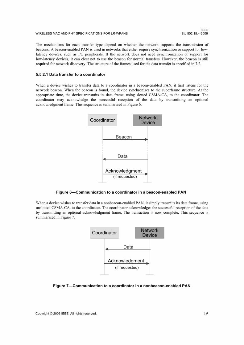
5.5.2.1 Data transfer to a coordinator
When a device wishes to transfer data to a coordinator in a beacon-enabled PAN, it first listens for thenetwork beacon. When the beacon is found, the device synchronizes to the superframe structure. At theappropriate time, the device transmits its data frame, using slotted CSMA-CA, to the coordinator. Thecoordinator may acknowledge the successful reception of the data by transmitting an optionalacknowledgment frame. This sequence is summarized in Figure 6.
When a device wishes to transfer data in a nonbeacon-enabled PAN, it simply transmits its data frame, usingunslotted CSMA-CA, to the coordinator. The coordinator acknowledges the successful reception of the databy transmitting an optional acknowledgment frame. The transaction is now complete. This sequence issummarized in Figure 7.
Figure 6—Communication to a coordinator in a beacon-enabled PAN
Coordinator Network Device
Beacon
Data
Acknowledgment(if requested)
Figure 7—Communication to a coordinator in a nonbeacon-enabled PAN
Coordinator Network Device
Data
Acknowledgment(if requested)

IEEEStd 802.15.4-2006 LOCAL AND METROPOLITAN AREA NETWORKS—PART 15.4:
20 Copyright © 2006 IEEE. All rights reserved.
5.5.2.2 Data transfer from a coordinator
When the coordinator wishes to transfer data to a device in a beacon-enabled PAN, it indicates in thenetwork beacon that the data message is pending. The device periodically listens to the network beacon and,if a message is pending, transmits a MAC command requesting the data, using slotted CSMA-CA. Thecoordinator acknowledges the successful reception of the data request by transmitting an acknowledgmentframe. The pending data frame is then sent using slotted CSMA-CA or, if possible, immediately after theacknowledgment (see 7.5.6.3). The device may acknowledge the successful reception of the data bytransmitting an optional acknowledgment frame. The transaction is now complete. Upon successfulcompletion of the data transaction, the message is removed from the list of pending messages in the beacon.This sequence is summarized in Figure 8.
When a coordinator wishes to transfer data to a device in a nonbeacon-enabled PAN, it stores the data for theappropriate device to make contact and request the data. A device may make contact by transmitting a MACcommand requesting the data, using unslotted CSMA-CA, to its coordinator at an application-defined rate.The coordinator acknowledges the successful reception of the data request by transmitting anacknowledgment frame. If a data frame is pending, the coordinator transmits the data frame, using unslottedCSMA-CA, to the device. If a data frame is not pending, the coordinator indicates this fact either in theacknowledgment frame following the data request or in a data frame with a zero-length payload (see7.5.6.3). If requested, the device acknowledges the successful reception of the data frame by transmitting anacknowledgment frame. This sequence is summarized in Figure 9.
Figure 8—Communication from a coordinator a beacon-enabled PAN
Coordinator Network Device
Beacon
Data
Acknowledgment
Data Request
Acknowledgment
Figure 9—Communication from a coordinator in a nonbeacon-enabled PAN
Coordinator Network Device
Data
Acknowledgment
Data Request
Acknowledgment

IEEEWIRELESS MAC AND PHY SPECIFICATIONS FOR LR-WPANS Std 802.15.4-2006
Copyright © 2006 IEEE. All rights reserved. 21
5.5.2.3 Peer-to-peer data transfers
In a peer-to-peer PAN, every device may communicate with every other device in its radio sphere ofinfluence. In order to do this effectively, the devices wishing to communicate will need to either receiveconstantly or synchronize with each other. In the former case, the device can simply transmit its data usingunslotted CSMA-CA. In the latter case, other measures need to be taken in order to achieve synchronization.Such measures are beyond the scope of this standard.
5.5.3 Frame structure
The frame structures have been designed to keep the complexity to a minimum while at the same timemaking them sufficiently robust for transmission on a noisy channel. Each successive protocol layer adds tothe structure with layer-specific headers and footers. This standard defines four frame structures:
— A beacon frame, used by a coordinator to transmit beacons
— A data frame, used for all transfers of data
— An acknowledgment frame, used for confirming successful frame reception
— A MAC command frame, used for handling all MAC peer entity control transfers
The structure of each of the four frame types is described in 5.5.3.1 through 5.5.3.4. The diagrams in thesesubclauses illustrate the fields that are added by each layer of the protocol.
5.5.3.1 Beacon frame
Figure 10 shows the structure of the beacon frame, which originates from within the MAC sublayer. Acoordinator can transmit network beacons in a beacon-enabled PAN. The MAC payload contains thesuperframe specification, GTS fields, pending address fields, and beacon payload (see 7.2.2.1). The MACpayload is prefixed with a MAC header (MHR) and appended with a MAC footer (MFR). The MHRcontains the MAC Frame Control field, beacon sequence number (BSN), addressing fields, and optionallythe auxiliary security header. The MFR contains a 16-bit frame check sequence (FCS). The MHR, MACpayload, and MFR together form the MAC beacon frame (i.e., MPDU).
The MAC beacon frame is then passed to the PHY as the PHY service data unit (PSDU), which becomes thePHY payload. The PHY payload is prefixed with a synchronization header (SHR), containing the PreambleSequence and Start-of-Frame Delimiter (SFD) fields, and a PHY header (PHR) containing the length of thePHY payload in octets. The SHR, PHR, and PHY payload together form the PHY packet (i.e., PPDU).
Figure 10—Schematic view of the beacon frame and the PHY packet
PHY layer
Beacon Payload
MAC Payload
n
MFR
2
PHY Payload
PSDU
7 + (4 to 24) + k + m + n
Frame Length / Reserved
1
PHR (see clause 6) + 8 + (4 to 24) + k + m + n
Preamble Sequence
MAC sublayer
PHY dependent (see clause 6)
SHR
MHR
Frame Control
Addressing Fields
Sequence Number
Superframe Specification
GTS Fields FCS
2 4 or 10 1 2 m
Start of Frame Delimiter
Octets:
Octets:
Pending Address Fields
kAuxiliary Security Header
0, 5, 6, 10 or14

IEEEStd 802.15.4-2006 LOCAL AND METROPOLITAN AREA NETWORKS—PART 15.4:
22 Copyright © 2006 IEEE. All rights reserved.
5.5.3.2 Data frame
Figure 11 shows the structure of the data frame, which originates from the upper layers.
The data payload is passed to the MAC sublayer and is referred to as the MAC service data unit (MSDU).The MAC payload is prefixed with an MHR and appended with an MFR. The MHR contains the FrameControl field, data sequence number (DSN), addressing fields, and optionally the auxiliary security header.The MFR is composed of a 16-bit FCS. The MHR, MAC payload, and MFR together form the MAC dataframe, (i.e., MPDU).
The MPDU is passed to the PHY as the PSDU, which becomes the PHY payload. The PHY payload isprefixed with an SHR, containing the Preamble Sequence and SFD fields, and a PHR containing the lengthof the PHY payload in octets. The preamble sequence and the data SFD enable the receiver to achievesymbol synchronization. The SHR, PHR, and PHY payload together form the PHY packet, (i.e., PPDU).
5.5.3.3 Acknowledgment frame
Figure 12 shows the structure of the acknowledgment frame, which originates from within the MACsublayer. The MAC acknowledgment frame is constructed from an MHR and an MFR; it has no MACpayload. The MHR contains the MAC Frame Control field and DSN. The MFR is composed of a 16-bitFCS. The MHR and MFR together form the MAC acknowledgment frame (i.e., MPDU).
The MPDU is passed to the PHY as the PSDU, which becomes the PHY payload. The PHY payload isprefixed with the SHR, containing the Preamble Sequence and SFD fields, and the PHR containing thelength of the PHY payload in octets. The SHR, PHR, and PHY payload together form the PHY packet, (i.e.,PPDU).
Figure 11—Schematic view of the data frame and the PHY packet
PHY layer
Data Payload
MAC Payload
n
FCS
MFR
2
Sequence Number
1 4 to 20
Addressing Fields
2
Frame Control
MHR
PSDU
PHY Payload
5 + (4 to 34) + n
Frame Length / Reserved
1
PHR (see clause 6) + 6 + (4 to 34) + n
Start of Frame Delimiter
Preamble Sequence
MAC sublayer
PHY dependent (see clause 6)
SHR
Octets:
Octets:
0, 5, 6, 10 or 14
Auxiliary Security Header
Figure 12—Schematic view of the acknowledgment frame and the PHY packet
PHY layer
2
MHR MFR
1
Frame Control
PSDU
PHY Payload
5
(see clause 6) + 6
Preamble Sequence
MAC sublayer
1Frame
Length / Reserved
SHR
PHY dependent (see clause 6)
PHR
Sequence Number
FCS
2
Start of Frame
Delimiter
Octets:
Octets:

IEEEWIRELESS MAC AND PHY SPECIFICATIONS FOR LR-WPANS Std 802.15.4-2006
Copyright © 2006 IEEE. All rights reserved. 23
5.5.3.4 MAC command frame
Figure 13 shows the structure of the MAC command frame, which originates from within the MACsublayer. The MAC payload contains the Command Type field and the command payload (see 7.2.2.4). TheMAC payload is prefixed with an MHR and appended with an MFR. The MHR contains the MAC FrameControl field, DSN, addressing fields, and optionally the auxiliary security header. The MFR contains a 16-bit FCS. The MHR, MAC payload, and MFR together form the MAC command frame, (i.e., MPDU).
The MPDU is then passed to the PHY as the PSDU, which becomes the PHY payload. The PHY payload isprefixed with an SHR, containing the Preamble Sequence and SFD fields, and a PHR containing the lengthof the PHY payload in octets. The preamble sequence enables the receiver to achieve symbolsynchronization. The SHR, PHR, and PHY payload together form the PHY packet, (i.e., PPDU).
5.5.4 Improving probability of successful delivery
The IEEE 802.15.4 LR-WPAN employs various mechanisms to improve the probability of successful datatransmission. These mechanisms are the CSMA-CA mechanism, frame acknowledgment, and dataverification and are briefly discussed in 5.5.4.1 through 5.5.4.3.
5.5.4.1 CSMA-CA mechanism
The IEEE 802.15.4 LR-WPAN uses two types of channel access mechanism, depending on the networkconfiguration. Nonbeacon-enabled PANs use an unslotted CSMA-CA channel access mechanism, asdescribed in 7.5.1. Each time a device wishes to transmit data frames or MAC commands, it waits for arandom period. If the channel is found to be idle, following the random backoff, the device transmits its data.If the channel is found to be busy following the random backoff, the device waits for another random periodbefore trying to access the channel again. Acknowledgment frames are sent without using a CSMA-CAmechanism.
Beacon-enabled PANs use a slotted CSMA-CA channel access mechanism, where the backoff slots arealigned with the start of the beacon transmission. The backoff slots of all devices within one PAN arealigned to the PAN coordinator. Each time a device wishes to transmit data frames during the CAP, it locatesthe boundary of the next backoff slot and then waits for a random number of backoff slots. If the channel isbusy, following this random backoff, the device waits for another random number of backoff slots beforetrying to access the channel again. If the channel is idle, the device begins transmitting on the next availablebackoff slot boundary. Acknowledgment and beacon frames are sent without using a CSMA-CAmechanism.
Figure 13—Schematic view of the MAC command frame and the PHY packet
PHY layer
MAC Payload
n
FCS
MFR
2
Sequence Number
1 4 to 20
Addressing Fields
2
Frame Control
MHR
PSDU
PHY Payload
6 + (4 to 34) + n Frame
Length / Reserved
1
PHR (see clause 6) + 7 + (4 to 34) + n
Preamble Sequence
MAC sublayer
PHY dependent (see clause 6)
SHR
Command Type
Command Payload
1
Start of Frame
Delimiter
Octets:
Octets:
Auxiliary Security Header
0, 5, 6, 10, or 14

IEEEStd 802.15.4-2006 LOCAL AND METROPOLITAN AREA NETWORKS—PART 15.4:
24 Copyright © 2006 IEEE. All rights reserved.
5.5.4.2 Frame acknowledgment
A successful reception and validation of a data or MAC command frame can be optionally confirmed withan acknowledgment, as described in 7.5.6.4. If the receiving device is unable to handle the received dataframe for any reason, the message is not acknowledged.
If the originator does not receive an acknowledgment after some period, it assumes that the transmission wasunsuccessful and retries the frame transmission. If an acknowledgment is still not received after severalretries, the originator can choose either to terminate the transaction or to try again. When theacknowledgment is not required, the originator assumes the transmission was successful.
5.5.4.3 Data verification
In order to detect bit errors, an FCS mechanism employing a 16-bit International TelecommunicationUnion—Telecommunication Standardization Sector (ITU-T) cyclic redundancy check (CRC) is used todetect errors in every frame.
The FCS mechanism is discussed in 7.2.1.9.
5.5.5 Power consumption considerations
In many applications that use this standard, devices will be battery powered, and battery replacement orrecharging in relatively short intervals is impractical. Therefore, the power consumption is of significantconcern. This standard was developed with limited power supply availability in mind. However, thephysical implementation of this standard will require additional power management considerations that arebeyond the scope of this standard.
The protocol has been developed to favor battery-powered devices. However, in certain applications, someof these devices could potentially be mains powered. Battery-powered devices will require duty-cycling toreduce power consumption. These devices will spend most of their operational life in a sleep state; however,each device periodically listens to the RF channel in order to determine whether a message is pending. Thismechanism allows the application designer to decide on the balance between battery consumption andmessage latency. Higher powered devices have the option of listening to the RF channel continuously.
5.5.6 Security
From a security perspective, wireless ad hoc networks are no different from any other wireless network.They are vulnerable to passive eavesdropping attacks and potentially even active tampering becausephysical access to the wire is not required to participate in communications. The very nature of ad hocnetworks and their cost objectives impose additional security constraints, which perhaps make thesenetworks the most difficult environments to secure. Devices are low-cost and have limited capabilities interms of computing power, available storage, and power drain; and it cannot always be assumed they have atrusted computing base nor a high-quality random number generator aboard. Communications cannot relyon the online availability of a fixed infrastructure and might involve short-term relationships betweendevices that may never have communicated before. These constraints might severely limit the choice ofcryptographic algorithms and protocols and would influence the design of the security architecture becausethe establishment and maintenance of trust relationships between devices need to be addressed with care. Inaddition, battery lifetime and cost constraints put severe limits on the security overhead these networks cantolerate, something that is of far less concern with higher bandwidth networks. Most of these securityarchitectural elements can be implemented at higher layers and may, therefore, be considered to be outsidethe scope of this standard.
The cryptographic mechanism in this standard is based on symmetric-key cryptography and uses keys thatare provided by higher layer processes. The establishment and maintenance of these keys are outside the

IEEEWIRELESS MAC AND PHY SPECIFICATIONS FOR LR-WPANS Std 802.15.4-2006
Copyright © 2006 IEEE. All rights reserved. 25
scope of this standard. The mechanism assumes a secure implementation of cryptographic operations andsecure and authentic storage of keying material.
The cryptographic mechanism provides particular combinations of the following security services:— Data confidentiality: Assurance that transmitted information is only disclosed to parties for which it
is intended.— Data authenticity: Assurance of the source of transmitted information (and, hereby, that information
was not modified in transit).— Replay protection: Assurance that duplicate information is detected.
The actual frame protection provided can be adapted on a frame-by-frame basis and allows for varyinglevels of data authenticity (to minimize security overhead in transmitted frames where required) and foroptional data confidentiality. When nontrivial protection is required, replay protection is always provided.
Cryptographic frame protection may use a key shared between two peer devices (link key) or a key sharedamong a group of devices (group key), thus allowing some flexibility and application-specific tradeoffsbetween key storage and key maintenance costs versus the cryptographic protection provided. If a group keyis used for peer-to-peer communication, protection is provided only against outsider devices and not againstpotential malicious devices in the key-sharing group.
For more detailed information on the cryptographic security mechanisms used for protected MAC framesfollowing this standard, refer to Clause 7.
5.6 Concept of primitives
This subclause provides a brief overview of the concept of service primitives. Refer to ISO/IEC 8802.25 formore detailed information.
The services of a layer are the capabilities it offers to the user in the next higher layer or sublayer by buildingits functions on the services of the next lower layer. This concept is illustrated in Figure 14, showing theservice hierarchy and the relationship of the two correspondent N-users and their associated N-layer (orsublayer) peer protocol entities.
5For information on references, see Clause 2.
Figure 14—Service primitives
Service Provider(N-layer)Service User
(N-User)Service User
(N-User)Request
Indication
ResponseConfirm

IEEEStd 802.15.4-2006 LOCAL AND METROPOLITAN AREA NETWORKS—PART 15.4:
26 Copyright © 2006 IEEE. All rights reserved.
The services are specified by describing the information flow between the N-user and the N-layer. Thisinformation flow is modeled by discrete, instantaneous events, which characterize the provision of a service.Each event consists of passing a service primitive from one layer to the other through a layer SAP associatedwith an N-user. Service primitives convey the required information by providing a particular service. Theseservice primitives are an abstraction because they specify only the provided service rather than the means bywhich it is provided. This definition is independent of any other interface implementation.
A service is specified by describing the service primitives and parameters that characterize it. A service mayhave one or more related primitives that constitute the activity that is related to that particular service. Eachservice primitive may have zero or more parameters that convey the information required to provide theservice.
A primitive can be one of four generic types:— Request: The request primitive is passed from the N-user to the N-layer to request that a service is
initiated.— Indication: The indication primitive is passed from the N-layer to the N-user to indicate an internal
N-layer event that is significant to the N-user. This event may be logically related to a remoteservice request, or it may be caused by an N-layer internal event.
— Response: The response primitive is passed from the N-user to the N-layer to complete a procedurepreviously invoked by an indication primitive.
— Confirm: The confirm primitive is passed from the N-layer to the N-user to convey the results of oneor more associated previous service requests.
![The MAC layer in wireless networks - unibo.it · The MAC layer in wireless networks The wireless MAC layer roles ... MACA [Karn1990]: ... "MACAW: A Media Access Protocol for …](https://img.pdfslide.us/doc/110x75/5b5b7a167f8b9a302a8e0f73/the-mac-layer-in-wireless-networks-uniboit-the-mac-layer-in-wireless-networks.jpg)